New Holland Boomer 41, Boomer 47 Compact Tractor. OPERATOR’S MANUAL (2014) - page 5
7 - MAINTENANCE
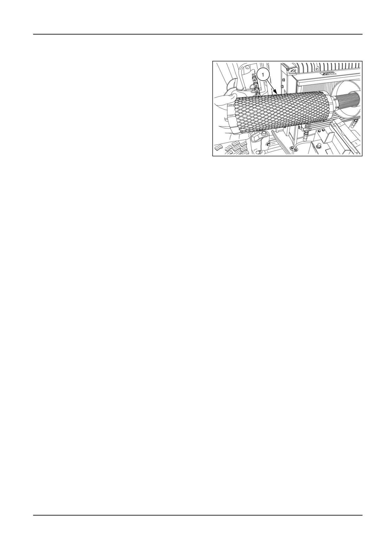
Air cleaner primary element
NOTE: Replace the primary element after every 300 hours
of service. Extremely dusty conditions may require more
frequent service intervals.
1. Pull the primary element (1) from the canister. Clean
any loose dirt from the canister and inspect the end of
the canister for dirt which may prevent the new element
from sealing properly.
2. Install the new primary element by inserting it into the
canister and pushing on the end of the element until it
is seated against the canister.
NOTE: If element is not inserted far enough into canister,
the end cap cannot be installed.
NHIL13CT00995AA
1
3. Place the end cap onto the canister body, push in on
end cap, and rotate clockwise. Make sure the end cap
is locked in place and not loose.
NOTICE: Failure to obtain a good seal between elements
and the canister may cause major engine damage.
7-27
7 - MAINTENANCE
Every 500 hours
Fuel filter
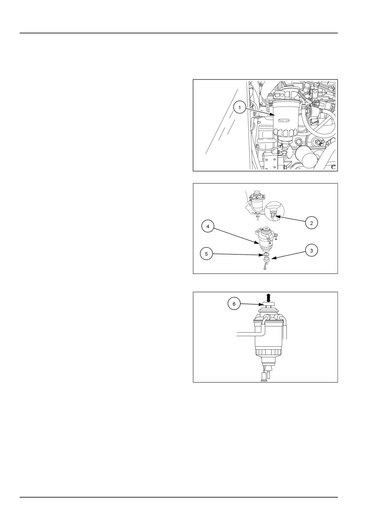
NOTE: Change the diesel fuel filter (1) after the first 50
hours of operation, then following every 500 operating
hours thereafter.
NHIL13CT01068AA
1
1. Loosen fuel filter drain plug (2) and drain fuel from the
filter.
2. Disconnect the electrical connector from the fuel filter
sensor (3).
3. Remove the fuel filter element (4) from the filter base
4. Remove the fuel filter sensor (3) from the original ele-
ment and install sensor with O-ring (5) onto new ele-
ment.
5. Install new element onto the filter base.
6. Connect electrical connector to the fuel filter sensor.
93100920
2
7. Tighten fuel filter drain plug.
8. Bleed the air from the fuel filter, by pressing the manual
fuel feed pump (6) several times. The manual feed
pump will bleed the air back to the fuel tank. There
is no need to open any bleed ports in the fuel system.
NHIL13CT01251AA
3
7-28
7 - MAINTENANCE
Every 600 hours
Front axle differential fluid
Changing front axle differential and final reduction gear case oil
NOTE: The front axle differential case and final reduction gear case oil should be changed after every 600 operating
hours.
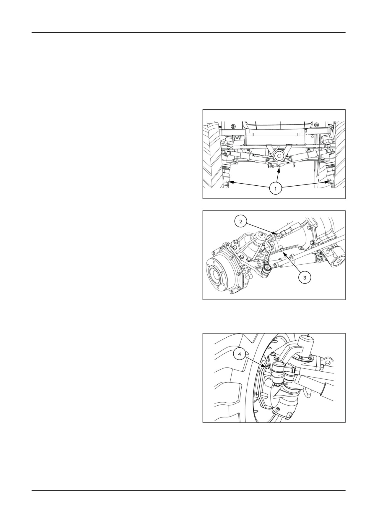
1. Place a suitable container beneath the oil plugs. With
the oil at normal operating temperature, drain the oil by
removing the drain plugs (1) After the oil has drained,
reinstall the drain plugs and discard the used oil.
93100925
1
2. Remove the filler plug (2) and check plugs (3).
3. Fill the axle with NEW HOLLAND AMBRA HYPOIDE 90
oil until the oil flows out of the oil level check plug port
(3) Reinstall the filler and check plugs, hand tight only.
93100921
2
4. Raise the front axle until both wheels are off the ground.
5. Tilt axle until stops are contacted.
6. Slowly and momentarily remove plug (4) from the lower
side final drive housing. This will allow any air that
is trapped in the lower housing to escape, so that the
correct oil level can be achieved. Reinstall plug and tilt
axle the opposite direction. Repeat this procedure for
the other final drive housing.
7. Lower axle back to the ground.
8. Recheck oil level at check plug port (3), add oil if
needed until the oil flows out of the oil level check plug
port.
9. After correct oil level is achieved, tighten all plugs.
93110427
3
NOTE: Approximate fluid capacity for the front axle housing is 8.0 l (8.4 US qt).
7-29
7 - MAINTENANCE
Transmission fluid
Changing the transmission, rear axle and hydraulic system oil level
NOTE: Change the transmission, rear axle, and hydraulic system oil after every 600 hours of operation.
NOTE: During cold weather operation, tractor hydraulic oil can be changed to NEW HOLLAND AMBRA F200A
HYDRAULIC FLUID . The F200Aoil is a multi-viscosity oil which has improved flow characteristics in low temperatures
and can be used year round.
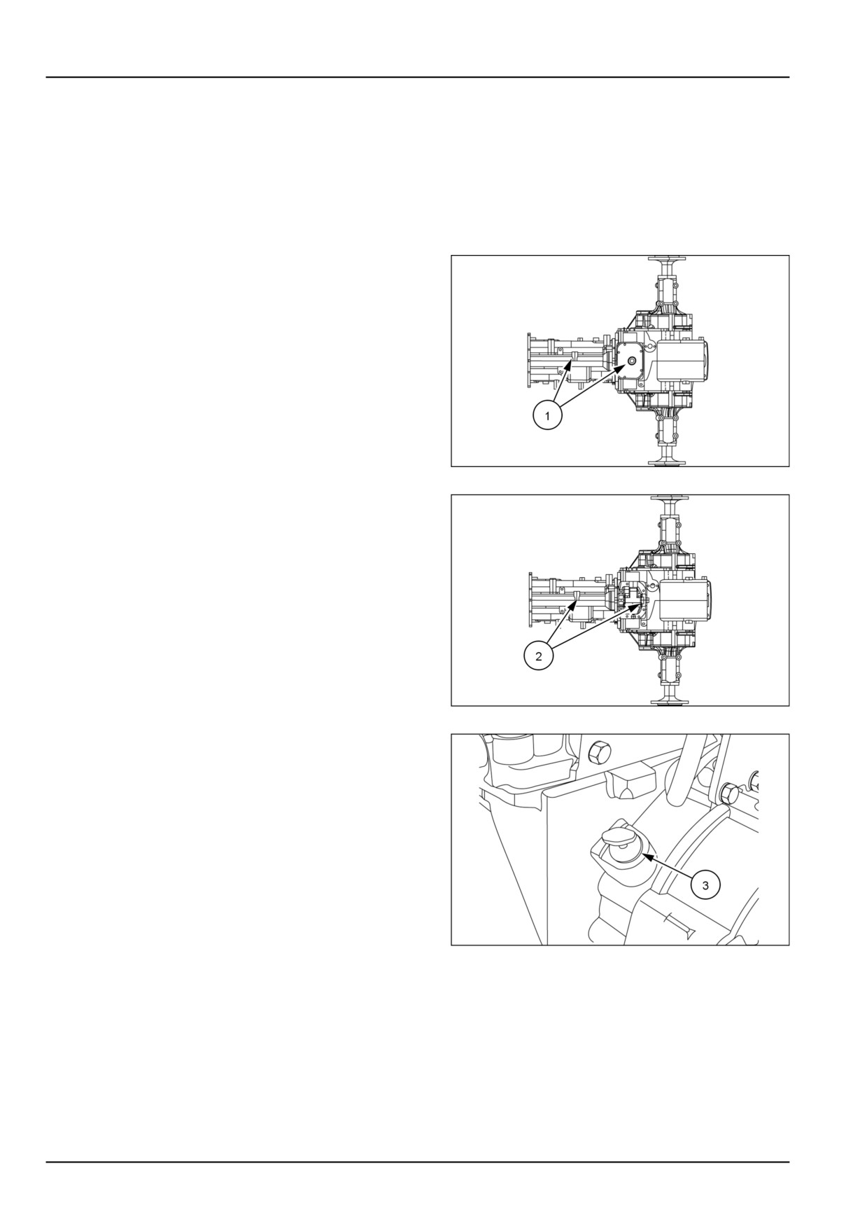
1. Place a suitable container beneath the transmission
and rear axle drain plugs (1) (without Mid PTO) and
(2)
(With Mid PTO) to catch the used oil. With the oil
at normal operating temperature, drain the system by
removing the transmission and rear axle drain plugs.
Reinstall the plugs once the oil has drained. Discard
the used oil.
93100871
1
93100872
2
2. Remove the dipstick (3) and fill with NEW HOLLAND
AMBRA MULTI G 134™ HYDRAULIC TRANSMISSION OIL
hydraulic oil. The transmission is filled to the correct
level when the oil registers between the two marks on
the dipstick.
Capacity:
• Gear transmission
43.0 l (11.4 US gal)
• HST transmission
43.0 l (11.4 US gal)
3. Reinstall the dipstick .
NOTICE: There is a common sump for the transmission,
rear axle, and hydraulic system. Therefore, extra care
93099360
3
should be taken to keep the oil clean
7-30
7 - MAINTENANCE
Every 1000 hours
Air cleaner inner element
NOTE: For maximum engine protection and air cleaner ser-
vice life, install a new inner safety element every third pri-
mary element change or after every 1000 hours of opera-
tion, whichever comes first.
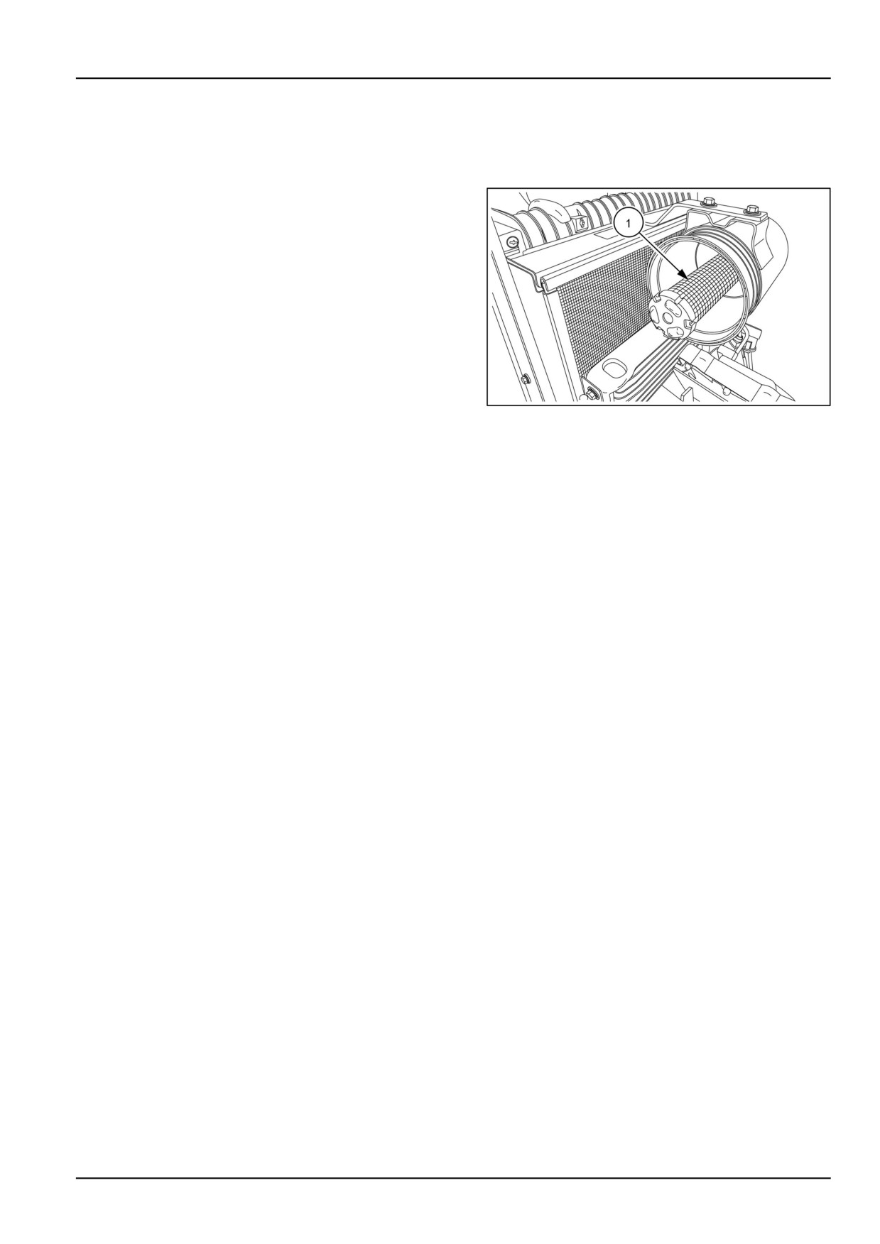
The air cleaner inner safety element (1) cannot be cleaned.
It must be replaced once it becomes partially clogged. A
clogged element will cause an air restriction resulting in a
loss of engine power or excessive black exhaust smoke.
NOTE: Conduct a visual inspection of the inner safety ele-
ment by placing a light inside the element. Little or no light
will shine through the element if it is partially clogged.
To remove the inner safety element, pull it out of the can-
NHIL13CT00997AA
1
ister body.
To install the new element, push it into the canister until
seated.
NOTICE: Clean any dirt from the canister before installing
the inner safety element. Check element inner diameter
seals for damage and replace the safety element if seal
damage is present.
NOTICE: Failure to obtain a good seal between the filter
and canister may cause major engine damage.
7-31
7 - MAINTENANCE
Engine coolant
WARNING
Hot liquid under pressure!
Never remove the filler cap or the recovery tank cap while the engine is running or the coolant is hot.
Let the system cool. Turn the filler cap to the first notch and allow any pressure to escape, and then
remove the filler cap. Loosen the recovery tank cap slowly to allow any pressure to escape.
Failure to comply could result in death or serious injury.
W0296A
Draining and flushing the cooling system
NOTE: Drain and flush the radiator and engine block ev-
ery 1000 hours of usage or 24 months, whichever comes
first. Refill with a 50/50 mixture of permanent antifreeze
and clear water.
To drain the cooling system:
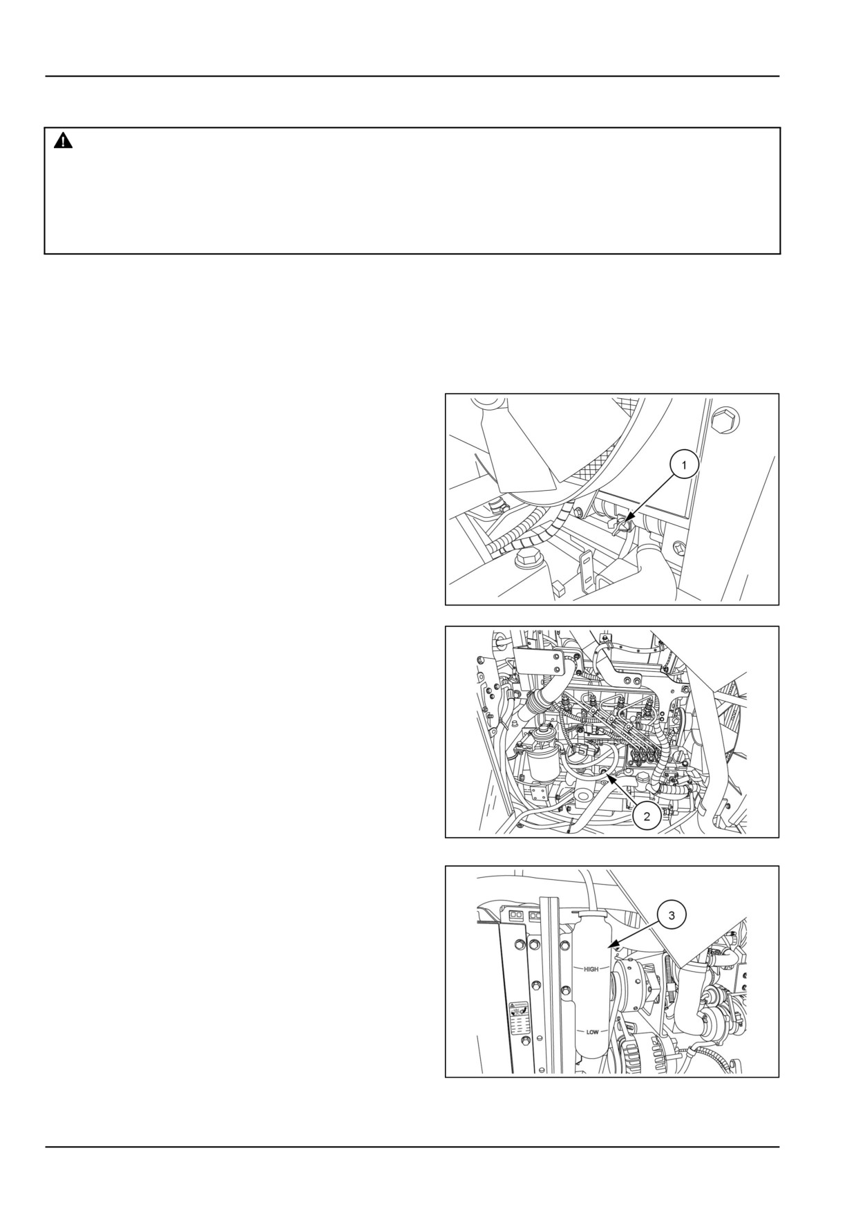
1. Use a suitable receptacle to catch the used coolant.
Remove the radiator cap and open the drain valve (1)
on the left- side of radiator to drain the radiator and
drain plug (2) on right side of engine block to drain
engine block.
2. After the coolant has drained, place a water hose in
the radiator filler neck and run water through the sys-
tem. When water is flowing from the block drain plug
port start the engine. When the water flowing from the
block port is free from coloration and sediment, stop the
engine and remove the hose. Allow all water to drain
from the system through the radiator drain valve and
block port.
NHIL13CT01051AA
1
3. Close the radiator drain valve and reinstall the block
drain plug. Slowly refill the system with a 50/50 solution
of ethylene glycol antifreeze and water. Fill until the
coolant level is approximately 4 cm (1.6 in) below the
bottom of the filler neck. Do not fill beyond this level.
4. Clean the radiator cap and cap seal and install the cap.
NHIL13CT01095AA
2
5. Add coolant to the coolant reservoir (3) until fluid level
is between the “LOW” and “HIGH” lines on the side of
the reservoir.
6. Run the engine until normal operating temperature is
reached, then stop the engine. Recheck the coolant
level when the engine is cold and add additional coolant
as necessary.
NOTICE: Never run the engine when the cooling system is
empty. Do not add cold water or cold antifreeze solution if
the engine is hot.
NHIL13CT01235AA
3
NOTE: Cooling system capacity is 7.5 L (2.0 US gal)
7-32
7 - MAINTENANCE
General maintenance
Fuel injection system - Bleed
Bleed the fuel system if:
• It has been drained.
• A new filter element has been installed.
• The tractor has run out of fuel.
• The lines leading to or from the filter have been dis-
connected.
• The injection pump has been removed and rein-
stalled.
WARNING
Escaping fluid!
Hydraulic fluid or diesel fuel leaking under
pressure can penetrate the skin and cause
infection or other injury. To prevent personal
injury: Relieve all pressure before discon-
necting fluid lines or performing work on the
hydraulic system. Before applying pressure,
make sure all connections are tight and all
components are in good condition. Never use
your hand to check for suspected leaks under
pressure. Use a piece of cardboard or wood
for this purpose. If injured by leaking fluid, see
your doctor immediately.
Failure to comply could result in death or seri-
ous injury.
W0178A
To bleed the fuel system:
1. Make sure there is adequate fuel in the fuel tank.
2. Place key switch in the “ON” position.
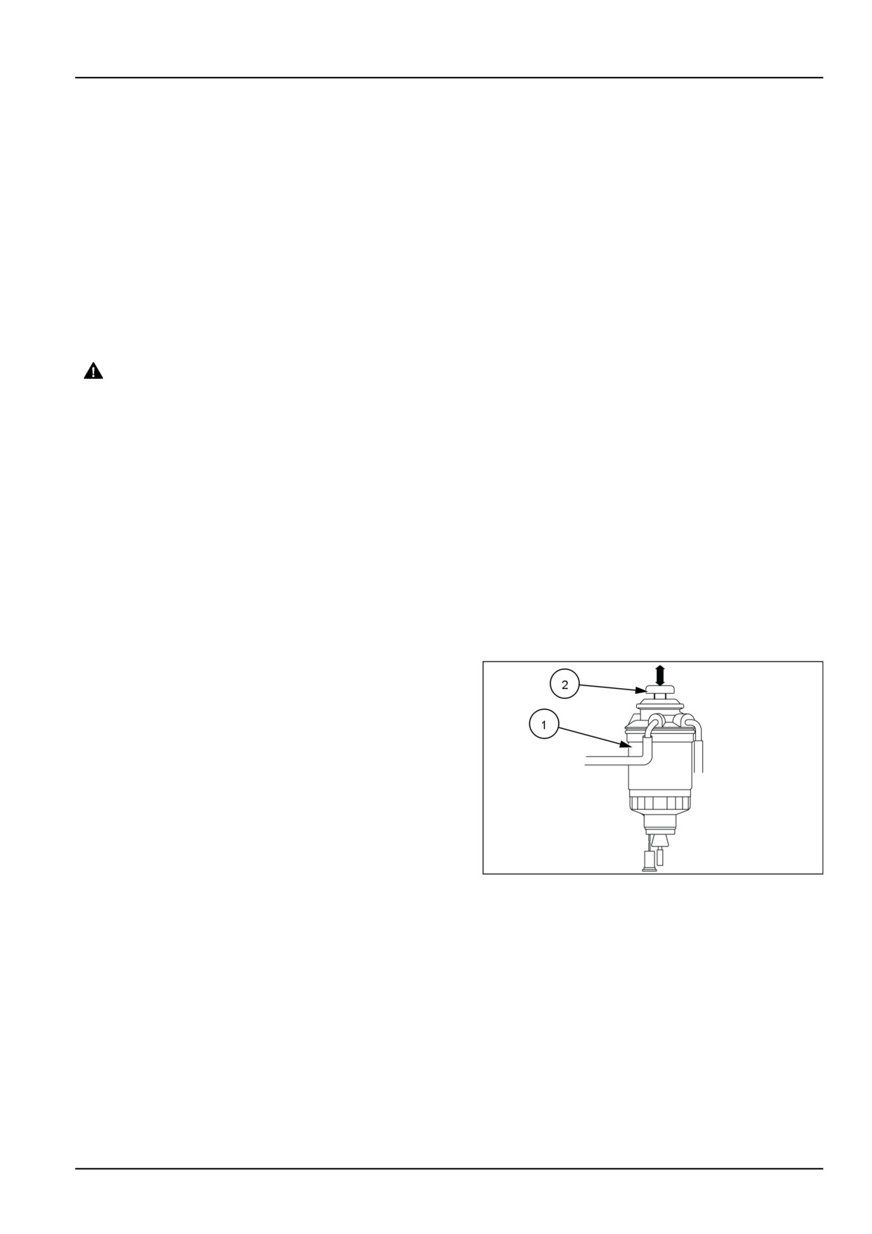
3. Bleed the air from the fuel filter (1), by pressing the
manual fuel feed pump (2) several times. The manual
feed pump will bleed the air back to the fuel tank. There
is no need to open any bleed ports in the fuel system.
NHIL13CT01251AA
1
7-33
7 - MAINTENANCE
NHIL13CT01357FA
2
Bleeding the injector lines
Bleed the injector lines if:
• The tractor has run out of fuel.
• New injectors have been installed.
• The injection pump has been removed for service
repairs.
To bleed the injector lines:
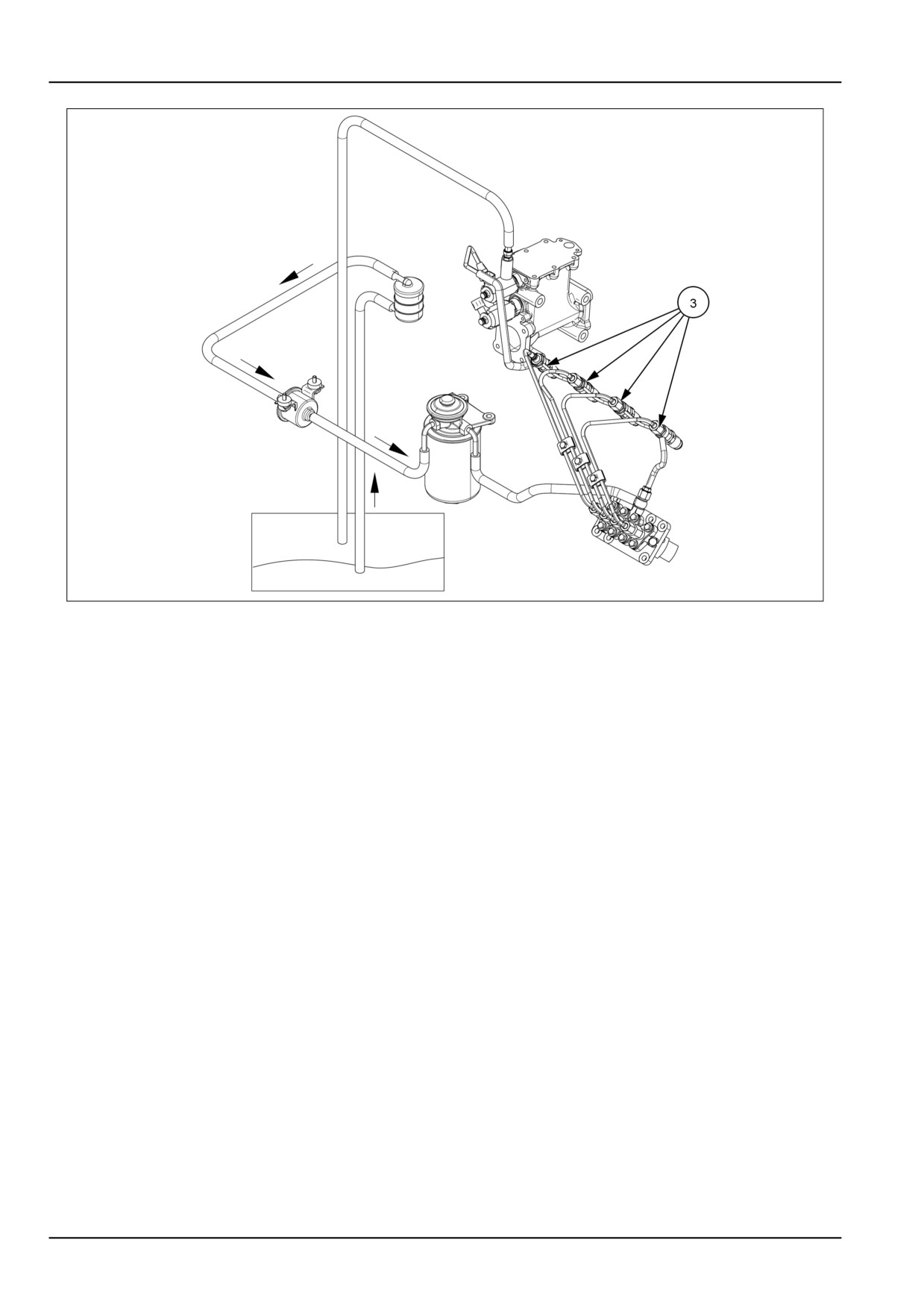
1. Loosen the injector line fittings (3) at the injectors, one
at a time.
2. Move the hand throttle control lever to its wide open
position.
3. Crank the engine until air-free fuel flows from each con-
nection, then tighten the fittings to 24 - 29 N·m (18 -
21 lb ft).
NOTICE: If air is not purged from the system, repeat the
above procedures. Do not crank the engine continuously
for more than 30 seconds as this may cause starting motor
failure.
7-34
7 - MAINTENANCE
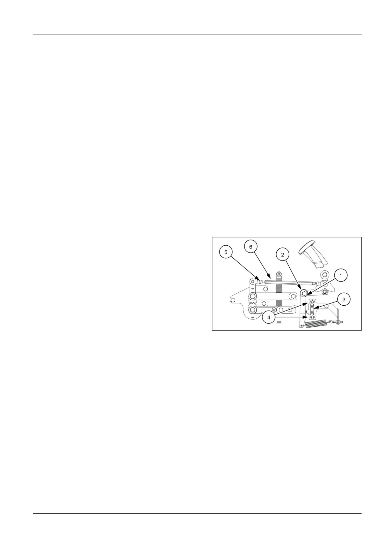
Hydrostatic transmission (HST) neutral adjustment
Checking HST return to "NEUTRAL"
1. Place range gear in "LOW" range and engine speed at
high idle position.
2. Drive tractor in forward and reverse, remove foot from
HST pedal. Tractor should stop and rear wheels should
not rotate when pedals are at "NEUTRAL" position.
3. If rear wheels rotate when HST pedals are in the "NEU-
TRAL" position , the HST control linkage needs to be
adjusted.
Adjusting "NEUTRAL" setting of HST control linkage
1. Park the tractor on level hard surface, with the engine
turned off.
NOTE: Before raising the rear wheels, install chocks between
the front axle and engine frame to prevent the front of the
tractor from oscillating side to side.
2. Raise the rear tires off the ground and support axles,
with safety stands.
3. Place the 4WD control lever in the "2WD" position.
4. The forward and reverse pedals should be at the same
height. Adjust pedal height by loosening bolt (1) and
rotating shaft (2) as needed. After height adjustment
is obtained, hold shaft (2) in place when tightening bolt
(1).
93100877
1
5. After pedal height adjustment, is completed, check that
HST neutral switch (3) is depressed when the pedals
are in the "NEUTRAL" position. If switch is not de-
pressed, loosen bolts (4) and adjust position of switch
so that switch is depressed. Tighten bolts after adjust-
ment is completed.
6. Start the tractor, place the range gear in "LOW" range
and engine speed at high idle.
7. Depress both forward and reverse pedals separately.
Release pedals and check if rear wheels rotate when
pedals return to the "NEUTRAL" position.
8. If rear wheels rotate when pedals are at the "NEU-
TRAL" position, adjust HST linkage by loosening jam
nuts (5) and rotating rod (6) until wheels do not rotate.
Tighten jam nuts after adjustment is completed.
9. Remove tractor from safety stands, when adjustment
is completed.
7-35
7 - MAINTENANCE
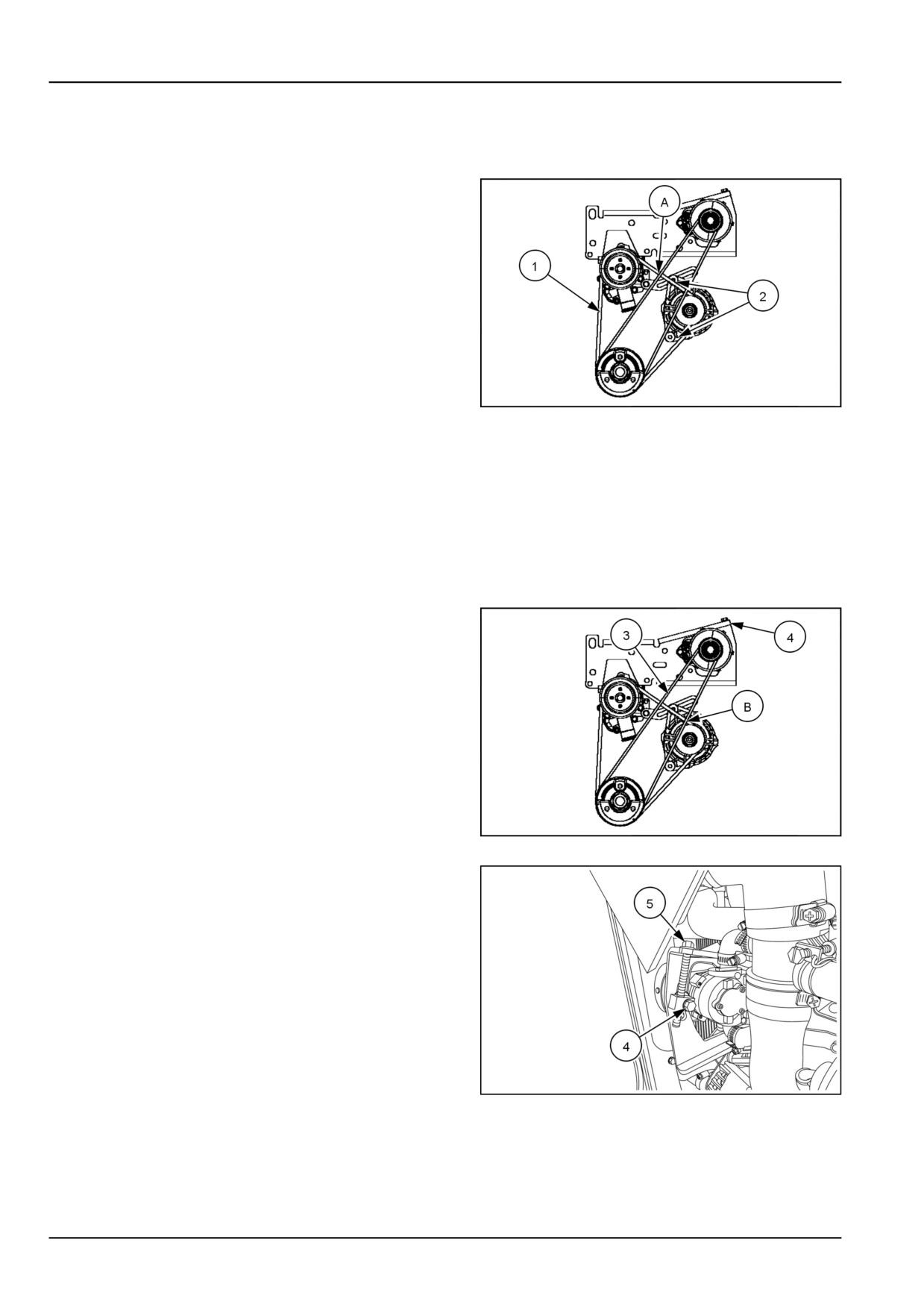
Engine belts
Fan and alternator belt
The belt- (1) that drives the cooling fan and alternator is
located at the front of the engine.
When 5 kg (11 lb) of pressure is applied midway between
the belt pulleys, a correctly tightened belt will deflect 5 mm
(0.2 in) .at point (A).
If the fan belt is slipping, fan efficiency is lowered, resulting
in the engine running too hot. or the alternator not charging
If the belt is too tight, the life of the alternator bearing will
be shortened. If the fan belt shows signs of cracking or
fraying, install a new one.
NHIL13CT01234AA
1
To adjust fan and alternator belt tension:
1. Loosen the two bolts (2) on the alternator , using a
prybar, pull the alternator away from the engine to
apply tension to belt.
2. When proper belt tension is achieved, tighten the
two alternator bolts.
Air pump belt
The belt (3) that drives the engine air pump is located at
the front of the engine.
When 5 kg (11 lb) of pressure is applied midway between
the belt pulleys, a correctly tightened belt will deflect
10 mm (0.4 in) .at point (B).
NHIL13CT01234AA
2
To adjust air pump belt tension:
1. Loosen air pump mounting bolt (4).
2. Rotate adjustment bolt (5) clockwise to tighten or
counterclockwise to loosen the belt tension.
3. When proper belt tension is achieved, tighten air
pump mounting bolt.
NHIL13CT01244AA
3
NOTE: If the air pump belt is slipping, pump efficiency is lowered. Resulting in the (DPF) burning not operating at
a high enough temperature or difficulty in starting burner. If the belt is too tight, the life of the pump bearing will be
shortened. If the fan belt shows signs of cracking or fraying, install a new one.
7-36
7 - MAINTENANCE
Roll Over Protective Structure (ROPS) frame - Replace - Possible
damage
If the unit has rolled over or the ROPS has been in some
other type of accident (such as hitting an overhead object
during transport), the ROPS must be replaced to retain the
best protection.
Following an accident, check the ROPS, the operator's
seat, and the seat belt and seat belt mountings for pos-
sible damage. Before operating the machine, replace all
damaged parts.
NOTICE: Do not attempt to weld or straighten the ROPS.
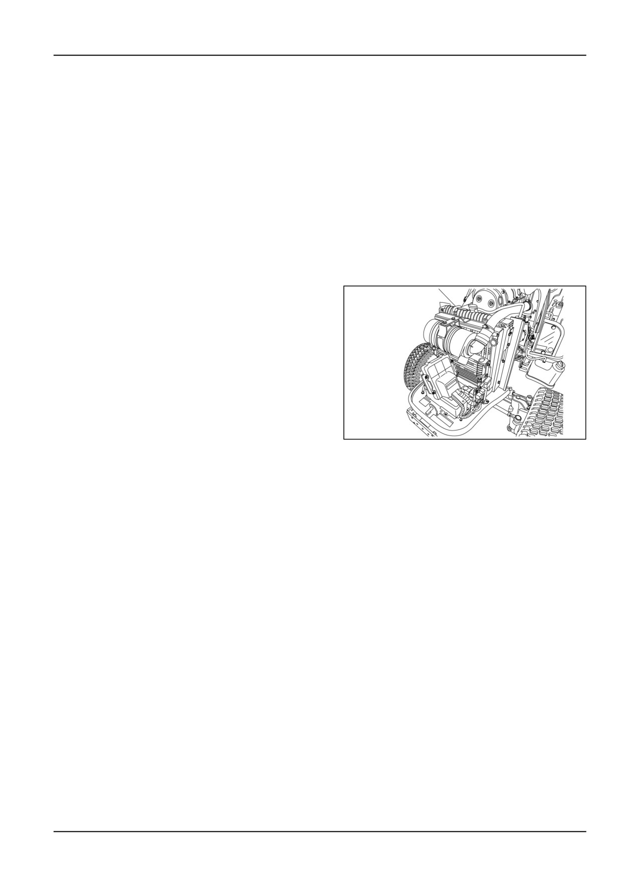
Battery
The tractor is equipped with a BCI group 34, 12 V battery
with a minimum cold cranking ability of 660 A at -18 °C
(0 °F).
Make sure the battery connections are tight and free of cor-
rosion. A solution of baking soda and water may be used
to wash the outside surface and terminals of the battery
when necessary. However, make sure the solution does
not get inside the battery. After cleaning, wash the battery
with clean water, then apply a small amount of petroleum
jelly to the terminals to prevent corrosion.
In freezing temperatures, a good battery charge must be
maintained. If the battery becomes discharged or run
down, the electrolyte becomes weak and may freeze,
causing damage to the case.
NHIL13CT01160AA
1
7-37
7 - MAINTENANCE
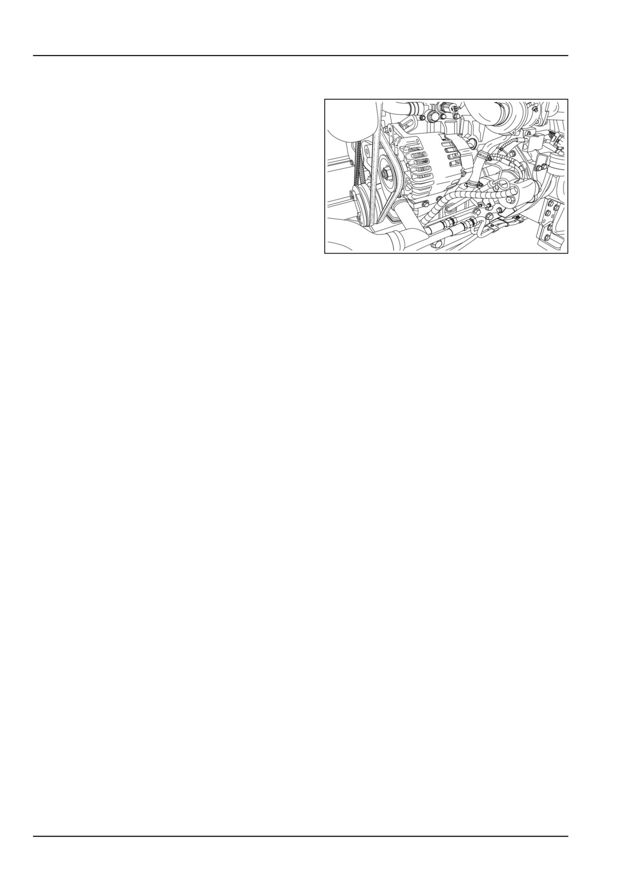
Alternator
The tractor's 85 A alternator is belt-driven from the engine
crankshaft pulley. It is important that belt slippage does not
occur, or the charging system will be affected. To adjust the
belt, see 7-36.
Other than belt adjustment, the only alternator mainte-
nance required is to periodically inspect the terminals to
ensure they are clean and tight. The alternator cooling fan
should also be cleaned periodically.
When working on or checking the alternator, adhere to fol-
lowing precautions or alternator damage may occur:
• Do not UNDER ANY CIRCUMSTANCES short the
field terminal of the alternator to ground.
• Do not disconnect the alternator output lead or bat-
NHIL13CT01039AA
1
tery cables while the alternator is operating.
• Do not remove the alternator from the tractor with-
out first disconnecting the negative (-) battery cable.
When removing the battery, disconnect the negative
(-) cable first.
• To install a battery, MAKE SURE that the positive
(+) cable is connected first and that the negative ter-
minal is connected to ground. Reverse polarity will
destroy the rectifier diodes in the alternator.
If the battery charge warning light illuminates, indicating
that the alternator is not charging the battery, check the
fan belt and the wiring connections. If these items are in
satisfactory condition and the warning light continues to
indicate no charge, consult your New Holland Dealer.
7-38
7 - MAINTENANCE
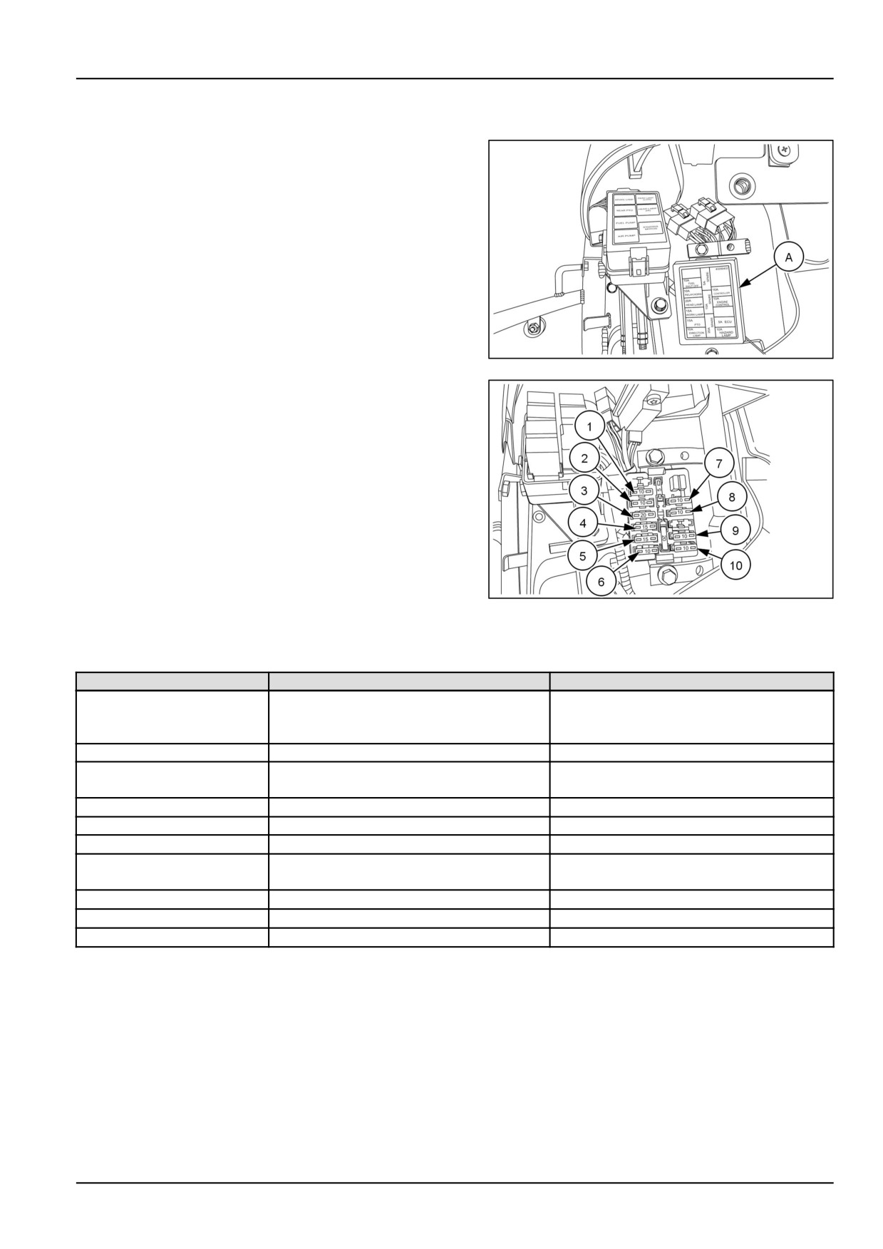
Fuses
The fuse block (A) is located on the left-hand side of the
steering column, underneath shrouding.
NOTICE: Always replace blown fuses with the size speci-
fied for that circuit.
NHIL13CT01000AA
1
NHIL13CT01343AA
2
From top to bottom the fuse block contains the following
fuses:
Fuse #
Fuse Size
Circuit Protected
1
10 A
Fuel shut off, Fuel pump, Engine air pump,
Engine start relay Engine controller, Glow
plug relay
2
10 A
Horn
3
20 A
Road lights, Brake lights, (DPF) burner
igniter
4
15 A
Front work lights,
5
15 A
PTO, Fuel filter sensor
6
10 A
Turn signals
7
10 A
Safety controller, Cruise control,
Instrument panel, (DPF) switch
8
10 A
Engine controller (ECU), Diagnostic plug
9
10 A
Spare circuit
10
10 A
Hazard lights
7-39
7 - MAINTENANCE
Maxi-fuse
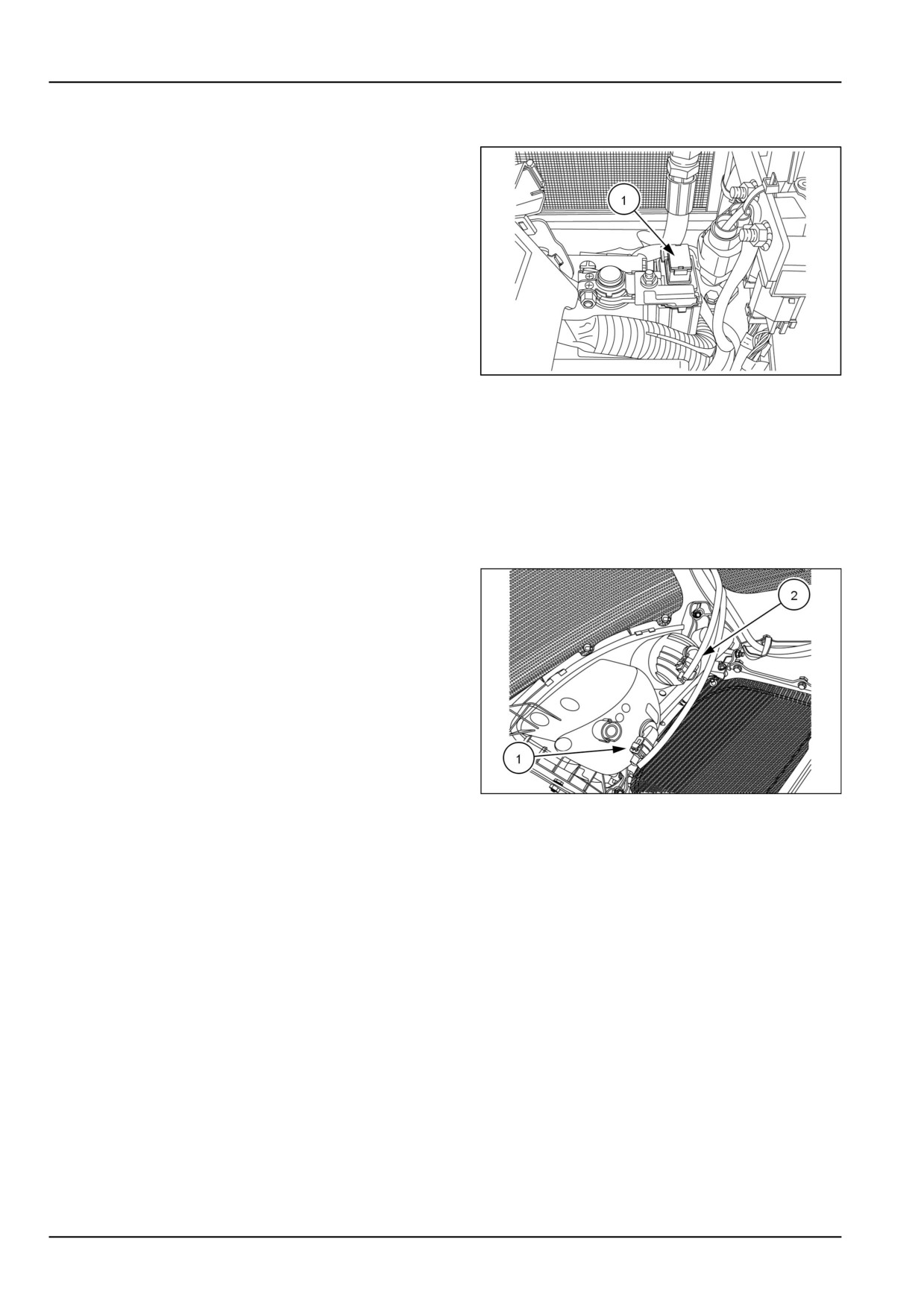
The main fuse is a 100 A fuse (1) located beside the battery
positive (+) terminal. This fuse protects the tractor's entire
electrical system.
NHIL13CT01247AA
1
To replace the main fuse:
1. Remove the old fuse from the fuse holder and replace.
NOTICE: Always replace this fuse with a 100 A fuse; DO
NOT increase amperage rating.
Headlight bulb
If head lamps, fail to operate, the bulb must be replaced.
To change the bulb:
1. Open the tractor hood.
2. Bulb Removal:
• Work (1) and Road lights (2). Turn bulb assembly ¼
turn and remove bulb from holder.
3. Bulb Replacement:
• Road and Work lights: Insert bulb assembly into
slots and turn ¼ turn clockwise to secure.
4. Rotate the socket counter-clockwise a quarter turn and
93100884
1
remove the socket from the housing.
5. Remove the bulb assembly from the harness.
6. Place a new bulb in the socket, then reinstall the socket
in the housing.
NOTICE: Be careful not to touch the bulb with bare fingers.
Oil from the fingers can shorten the life of bulb. Use pro-
tective cloth or glove when installing bulb.
NOTE: Replacement bulbs are:
Work lights (upper) : Bulb size 894, 37.5 W, Halogen.
Road lights (lower) : Bulb size 886, 50 W, Halogen.
7-40
7 - MAINTENANCE
Tail/brake light bulb
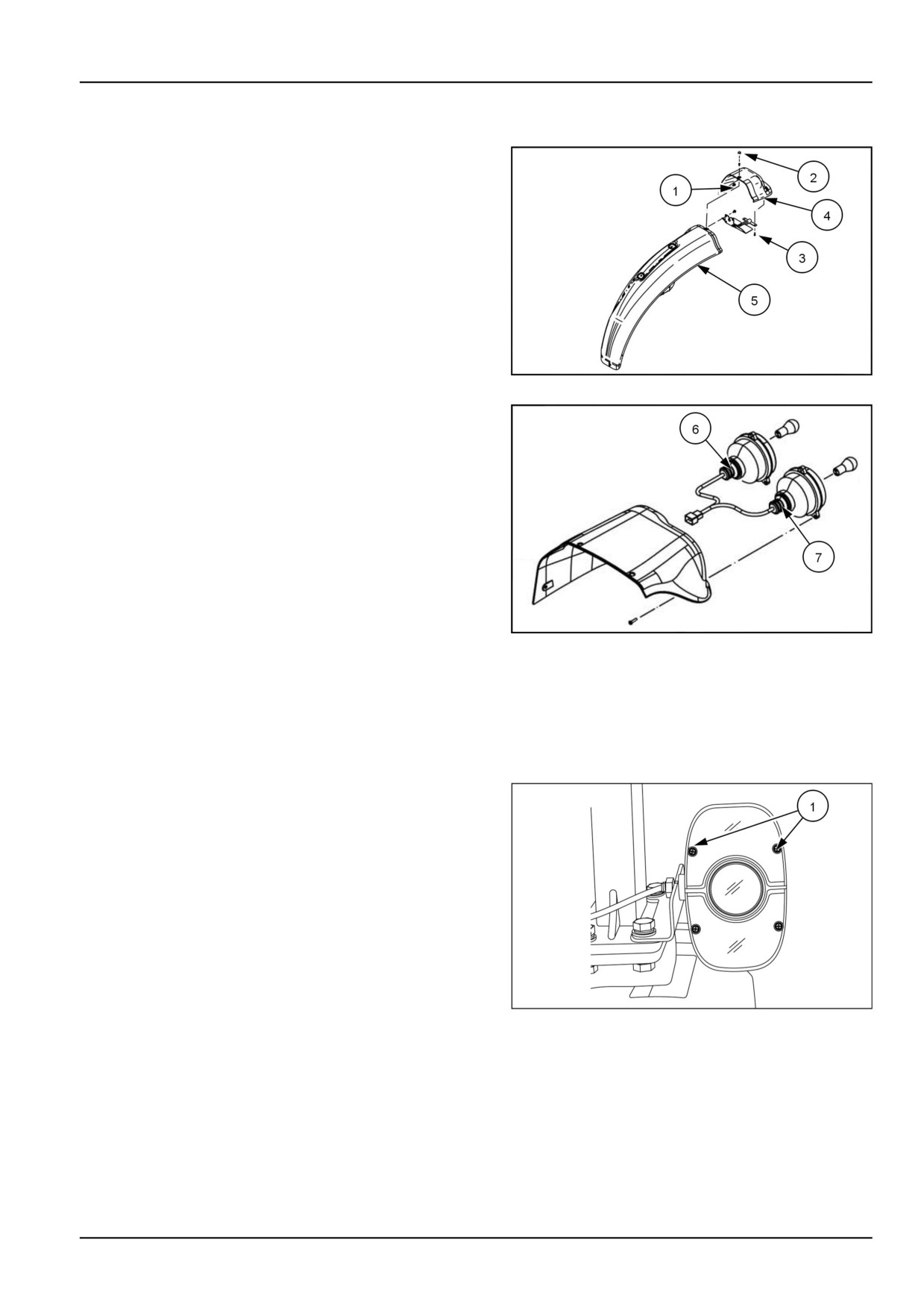
To replace a taillight bulb:
1. Remove the M6x16mm bolts (1),the plastic retainer (2)
and two M5 screws (3) that retain the taillight housing
(4) to the rear fender (5).
NHIL13CT01279AA
1
2. Push in on the brake/tail light bulb (6) or turn signal
bulb (7) and rotate counter-clockwise in the socket to
remove the old bulb.
3. Insert the new bulb into the socket and turn the bulb in
a clockwise direction until tightened.
NOTE: Replace brake/tail bulb (6) with a dual filament
21W/5W bulb. and turn signal bulb (7) with a single
filament 21W bulb.
NHIL13CT01278AA
2
4. Reinstall the taillight housing to the rear fender.
Turn signal/hazard light bulb
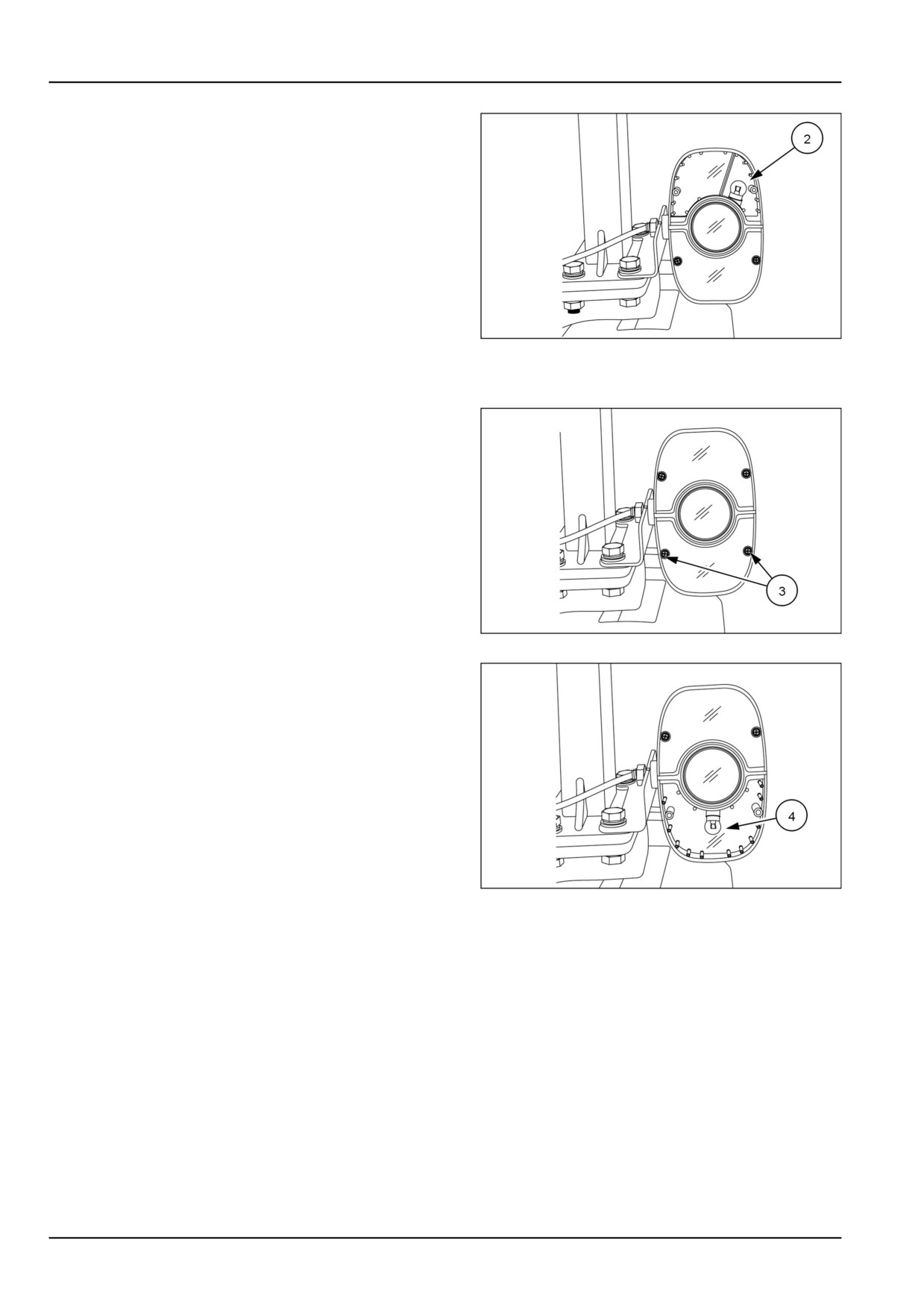
To replace the top flasher light bulb:
1. Remove the two screws (1) retaining the top flasher
light lenses and remove the lenses.
93100885
1
7-41
7 - MAINTENANCE
2. Push in on the bulb (2) and rotate bulb counter-clock-
wise in socket to remove.
NOTE: Replace with a P21 watt bulb.
3. Insert the new bulb into the socket and turn it clockwise
until the bulb locks into place.
4. Install lenses and retaining screws.
93100894
2
To replace the bottom flasher light bulb:
5. Remove the two screws (3) retaining the top flasher
light lenses and remove the lenses.
93100885
3
6. Push in on the bulb (4) and rotate bulb counter-clock-
wise in socket to remove.
NOTE: Replace with a R10 watt bulb.
7. Insert the new bulb into the socket and turn it clockwise
until the bulb locks into place.
8. Install lenses and retaining screws.
93100886
4
7-42
7 - MAINTENANCE
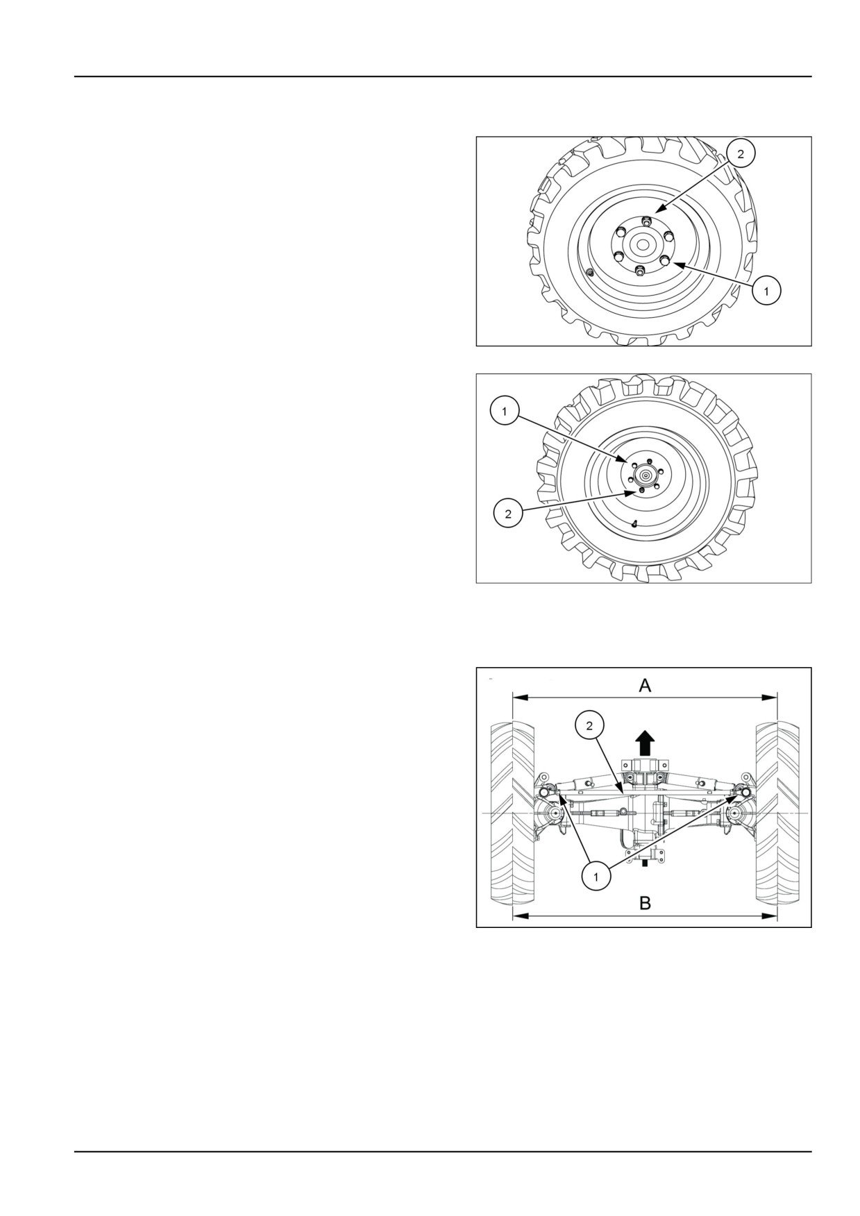
Wheels bolt/nut
Tighten the wheel bolts (1) and nuts (2) to the specified
torque any time the wheel assembly is removed from the
tractor or the wheel bolts are loosened.
Front Wheel Torque
•
176 - 196 N·m (130 - 145 lb ft)
93100874
1
Rear Wheel Torque
•
176 - 196 N·m (130 - 145 lb ft)
NOTICE: Check and tighten wheel bolts (1) and nuts (2)
to proper torque specifications after the following hours of
use:
• First 5 hours
• First 50 hours
• Every 300 hours
93100875A
2
Front wheels toe-in
If toe-in is not correct, adjust as follows:
1. Loosen the tie rod locknuts (1).
2. Adjust the tie rod tube assembly (2) as required to give
0 - 5 mm (0 - 0.2 in) toe-in.
3. After the correct toe-in is obtained, tighten the tie rod
locknuts.
20100932
1
7-43
7 - MAINTENANCE
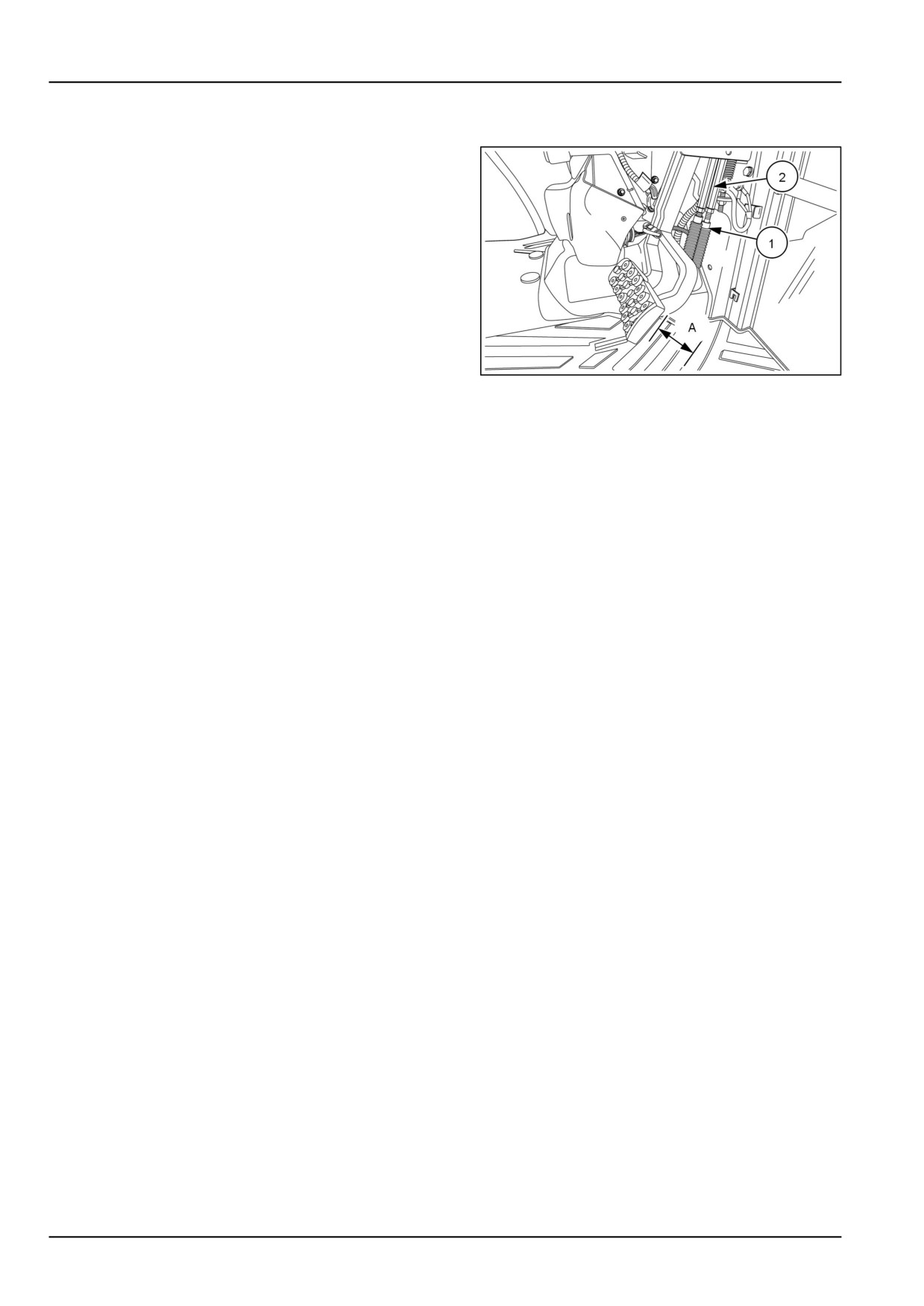
Brake pedal free play
Whenever brake pedal travel becomes excessive, pedal
free play should be adjusted.
1. Loosen the locknut (1) and rotate the brake rod (2) until
there is (A) = 50 - 60 mm (1.96 - 2.36 in) of pedal free
play. Lengthening the rod increases free play. Short-
ening the rod decreases free play.
NHIL13CT01246AA
1
NOTE: Adjust both pedals equally
2. Test drive the tractor to make sure the braking action of
both rear wheels is equal. Readjust as necessary.
7-44
7 - MAINTENANCE
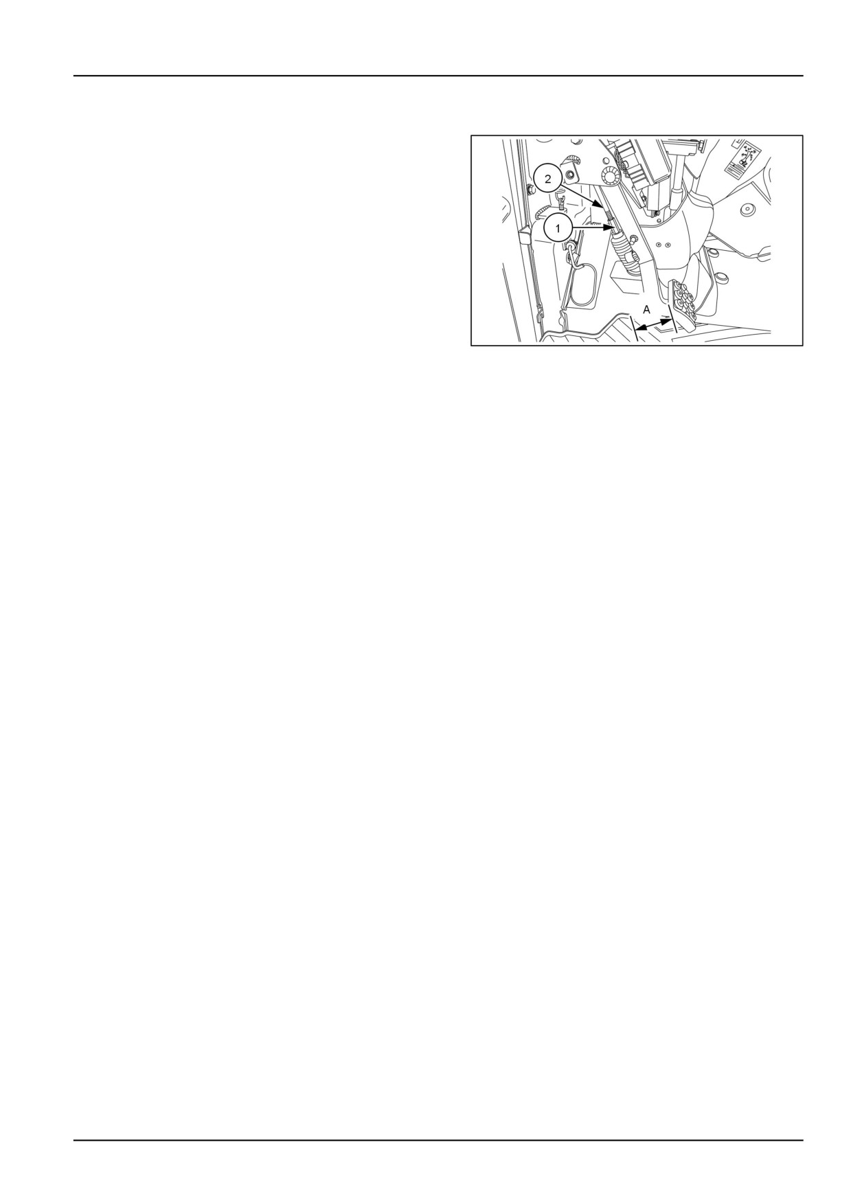
Clutch pedal free play
NOTE: Check clutch pedal free travel after every 50 hours
of operation.
Clutch pedal free travel should be maintained at A = 20 -
30 mm (0.79 - 1.18 in).
To adjust the clutch pedal:
1. Loosen lock nut (1) and rotate adjuster (2)
2. Tightening the adjuster will decrease the free play travel
and loosening the adjuster will increase the free play
travel.
3. Tighten the lock nut when the correct free play travel is
obtained
NHIL13CT01275AA
1
4. Check clutch for disengagement when clutch pedal is
fully depressed.
7-45
7 - MAINTENANCE
STORAGE
Storing the tractor
Below is a list of protective measures which should be
taken if your tractor is to be stored for an extended period
of time:
1. Thoroughly clean the tractor. Use touch up paint where
necessary to prevent rust.
2. Check the tractor for worn or damaged parts. Install
new parts as required.
3. Raise the lift arms hydraulically to their fullest raised
position so that the lift piston is in a fully extended po-
sition. This fills the cylinder with oil and protects the
cylinder wall surfaces from corrosion.
4. Lubricate the tractor.
5. Fill the fuel tank with No. 1 diesel fuel.
NOTICE: Do not use No. 2 diesel fuel for winter storage
because of wax separation and setting at low temperature.
6. Open the drain valve of the radiator and engine block.
Flush the system, close the drain valves, and fill with a
50/50 solution of permanent antifreeze and clear water.
7. Remove the battery and clean it thoroughly. Be sure
that it is fully charged and that the electrolyte is at the
proper level. Store the battery in a cool, dry place
above freezing temperature, and charge it periodically
during storage.
8. Place blocking under the tractor axles to remove the
weight from the tires.
9. Cover the exhaust pipe opening.
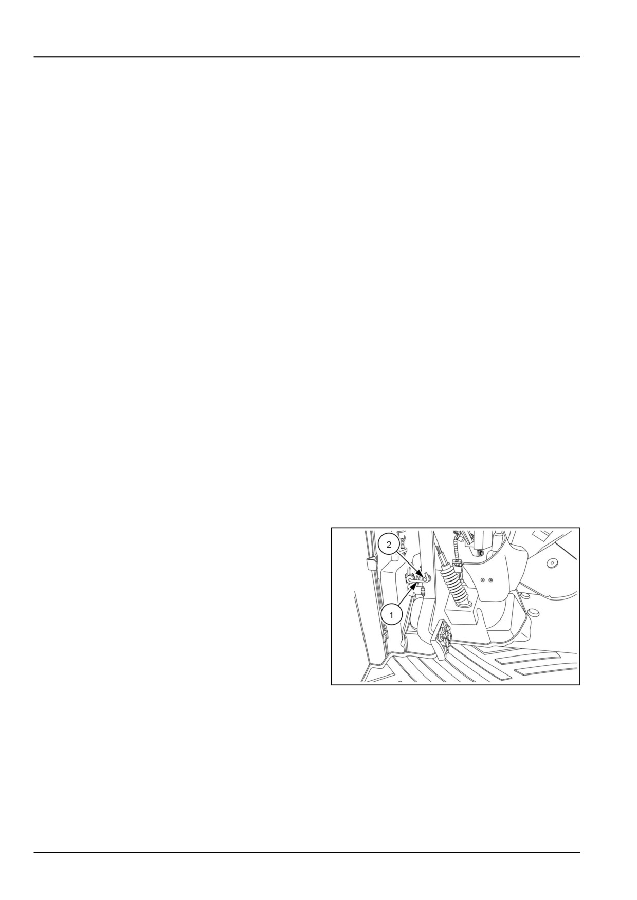
10. Depress the clutch pedal, engage the latch (1) with the
pin (2) located on the clutch pedal. When the clutch
pedal is locked in this position, the clutch disc will be
separated from the flywheel.
NOTE: The left side cover has to be removed to gain ac-
cess to the clutch pedal latch.
NHIL13CT01276AA
1
7-46
7 - MAINTENANCE
Removal of tractor from storage
Tractors which have been placed in storage should be com-
pletely serviced in the following manner before using:
1. Inflate the tires to the recommended pressures and re-
move the blocking.
2. Check the oil level in the engine crankcase, power
steering reservoir, the common sump (for the hydraulic
lift, transmission, and rear axle), and the optional front-
wheel drive axle.
3. Install a fully charged battery and remove the exhaust
cover if other than a rain cap.
4. Check the cooling system for the proper level (50/50
solution of antifreeze and clear water).
5. Start the engine and allow it to idle a few minutes. En-
sure the engine is receiving lubrication and that each
control is functioning correctly.
6. Drive the tractor without a load and check to make sure
it is operating satisfactorily.
Touch-up paint
The following New Holland paints are recommended for
touch-up paint repairs.
Color
Part No.
Amount
86109144-DS
16 oz Spray
New Holland Bright Blue
86109141-DS
1 US qt
B96104
16 oz Spray
CNH Dark Gray
B96105
1 US qt
9624698-DS
16 oz Spray
Bianco White (Wheels)
9624699-DS
1 US qt
94792-DS
16 oz Spray
Med Gloss Black
9624700-DS
1 US qt
7-47
8 - TROUBLESHOOTING
8 - TROUBLESHOOTING###_8_###
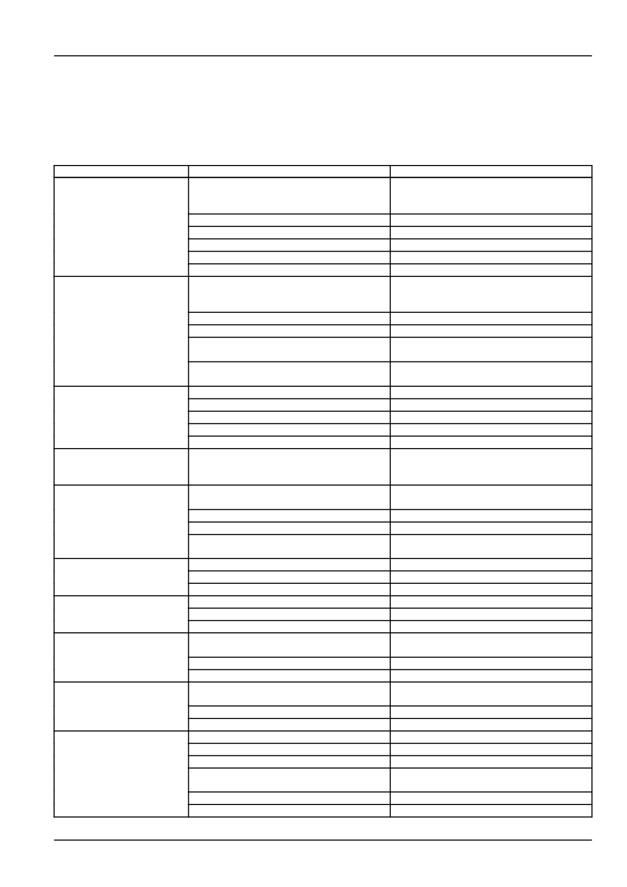
SYMPTOM(S)
Engine - Troubleshooting
Problem
Possible Cause
Correction
The start motor does not
Low battery charge
Charge or replace
rotate with the key switch
in the (START) position.
Loose battery or starter cable terminals
Tighten the terminal
Key switch faulty
Repair or replace switch
Safety start switch not completing circuit
Depress clutch pedal fully
PTO safety switch is not in "OFF" position
Place PTO switch in "OFF" position
Starter motor faulty
Repair or replace starter motor
The start motor rotates
Low battery charge
Charge or replace battery
but the engine does not
start
Air in fuel system
Bleed out the air
Fuel filter clogged
Clean or replace the filter
Fuel shutoff valve on fuel filter in closed
Open the valve
position
Fuel shutoff solenoid on fuel injection pump
Check solenoid for proper operation, repair
stuck in off position
as needed
Engine speed is irregular
Air in fuel system
Bleed the fuel system
Fuel filter clogged
Clean or replace the filter
Injection nozzle clogged
Repair or replace nozzle
Fuel leakage
Repair fuel system
Irregular fuel injection
Repair or replace fuel injection pump
Engine speed is more
Governor malfunction
Repair injection pump as needed
than maximum rated high
idle speed
Engine stops suddenly
Fuel shortage
Add fuel and bleed air from fuel system
during operation
Faulty fuel injector
Repair or replace injector
Faulty fuel injection pump
Repair or replace injection pump
Internal parts of engine seized due to lack
Repair engine as needed
of lubrication
Engine stops at low speed
Faulty injection pump
Repair or replace injection pump as needed
Engine valve gap is not correct
Adjust the gap
Low fuel injector pressure
Repair fuel injector as needed
Engine overheating
Lack of coolant
Add coolant as needed
Fan belt slipping or belt is broken
Adjust belt tension or replace belt
Dirt attached to the radiator or prescreen
Clean radiator fins or screen as needed
The color of exhaust
Low engine operating temperature
Allow engine to obtain higher operating
smoke is white
temperature
Engine burning engine oil
Repair engine as needed
Engine coolant entering engine exhaust
Repair engine as needed
The color of exhaust gas
Air filter clogged
Clean or replace engine air filter
is black.
Excessive fuel supply
Repair fuel injection pump as needed
Faulty fuel injector
Repair or replace fuel injector
Low engine power
Fuel injector nozzle clogged
Repair injector as needed
Carbon accumulation on valve seat
Repair valve and seats as needed
Incorrect valve gap adjustment
Adjust valve gap to correct amount
Incorrect fuel injection timing
Check and adjust fuel injection timing as
needed
Lack of fuel supply
Check fuel system for restriction
Air filter clogged
Clean or replace air filter
8-1
8 - TROUBLESHOOTING
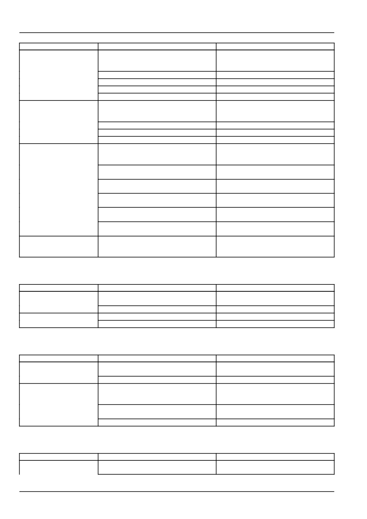
Problem
Possible Cause
Correction
Instrument panel engine
Lack of engine oil
Add engine oil as needed
oil pressure indicator light
is "ON" during operation.
Low viscosity of engine oil
Replace oil with proper viscosity type
Faulty pressure switch
Replace switch
Faulty engine oil pump
Repair oilpump as needed
Engine oil filter clogged
Replace the filter
Instrument panel battery
Bad electrical connection
Check battery terminals, ground, and repair
charging indicator is "ON"
as needed
during operation.
Faulty alternator
Repair or replace alternator as needed
Faulty battery
Replace battery
Incorrect fan belt tension or belt broken
Adjust belt tension or replace belt
Diesel Particulate Filter
Excessive soot build up in (DPF)
Start regeneration of (DPF) system
(DPF) and burner not
functioning properly
Air pump not working
Check air pump belt tension and electrical
current to air pump clutch
Burner not igniting
Defective burner injector, contact autho-
rized dealer
Burner not igniting
Defective burner ignitor, contact authorized
dealer
Burner not igniting
Insufficient fuel supply to burner, check
clogged fuel pre-filter.
Engine Control Unit (ECU) not functioning
Contact authorized dealer for electronic di-
properly
agnosis
Engine will only run
Excessive soot load in Diesel Particulate
Contact authorized dealer
for approximately thirty
Filter (DPF)
seconds
Clutch - Troubleshooting
Problem
Possible Cause
Correction
Clutch slips
Incorrect adjustment of clutch pedal free
Adjust the pedal free play correctly
play
Clutch disc lining worn or broken
Replace clutch disc
Clutch does not release
Excessive clutch pedal free play
Adjust the pedal free play
Clutch disc damaged
Repair or replace clutch disc
Hydraulic service brakes - Troubleshooting
Problem
Possible Cause
Correction
Brake does not work or
Incorrect brake pedal free play
Adjust brake pedal free play to correct
only one side works.
specification
Brake disc lining worn or broken
Replace brake discs as needed
After engaging brake
Return spring damaged
Replace the spring
pedal, pedal will not
return
Lack of lubrication in brake shaft linkage
Clean and lubricate linkage as needed
parts
Damaged internal brake parts
Repair internal brake parts as needed
Hydraulic Lift System - Troubleshooting
Problem
Possible Cause
Correction
The 3-point linkage will
Lack of transmission / hydraulic oil
Add oil as needed
not raise
8-2
8 - TROUBLESHOOTING
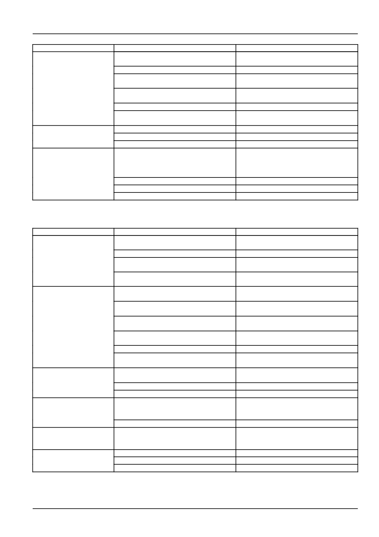
Problem
Possible Cause
Correction
Air in the hydraulic suction pipe
Tighten the hydraulic filter and check all hy-
draulic suction connections
Hydraulic filter clogged
Replace hydraulic filter
Faulty hydraulic pump
Check pump for proper flow replace pump
if needed
Faulty control valve
Check hydraulic control valve and linkage
for proper operation repair as needed
Faulty hydraulic lift cylinder
Repair lift cylinder as needed
Faulty hydraulic relief valve
Check hydraulic system for correct pres-
sure setting, repair as needed
Oil leakage
Connecting part loosened
Tighten
Oil seal damaged
Replace
Pipe cracked
Replace
The 3-point linkage does
Down speed control valve locked in closed
Turn the knob counterclockwise, to open
not move down when
position
valve
control handle is moved
to down position.
Control valve failure
Repair or replace valve
Hydraulic lift cylinder damaged
Repair cylinder as needed
Lift shaft moving parts damaged
Repair or replace lift shaft parts as needed
Steering - Troubleshooting
Problem
Possible Cause
Correction
Hydraulic steering system
Faulty power steering pump
Replace pump if needed
does not work
Steering unit damaged or worn
Repair or replace unit as needed
Steering cylinder piston seal damaged or
Repair cylinder as needed
worn
External oil leakage of oil tubes or hoses
Repair or replace tubes or hoses as
needed
Excessive steering wheel
Steering unit: Spline and column spline
Check mounted condition of steering unit
effort
does not align
and column
Steering unit: Spool and sleeve damaged
Replace steering unit
by foreign material
Steering unit: Excessive tightening torque
Apply proper torque of end cap hardware
of end cap bolt
Pump: Low flow
Increase engine RPM, to increase pump
flow
Faulty power steering pump
Check pump , repair or replace if needed
Power steering relief valve: pressure set-
Check power steering relief valve pressure
ting low
adjust to proper pressure setting
Cylinder movement not as
Air in steering line if not used for a long time
Bleed air in steering system
smooth as steering wheel
Air in suction tube
Check suction tube, repair as needed
Cylinder piston seal damaged
Repair cylinder as needed
Front wheels turn the
Incorrect assembly of steering gear
Repair steering gear as needed
opposite direction to the
steering wheel direction
Incorrect assembly of steering hoses
Assemblel steering hoses correctly
Oil leakage of steering
Seal damaged
Replace seal
pump, steering unit,
cylinder
Abnormal noise
Lack of oil
Add oil as needed
Restriction of oil flow in suction line
Replace filter
Air in system
Bleed air from system
8-3
8 - TROUBLESHOOTING
Hydrostatic transmission - Troubleshooting
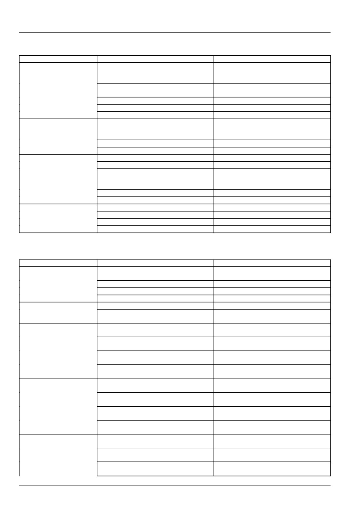
Problem
Possible Cause
Correction
When operating HST
HST high pressure relief valve pressure
Check HST pressure and repair as needed
pedal, tractor does not
setting low
move.
HST charge pressure valve faulty
Check HST charge pressure and repair as
needed
HST Filter clogged
Replace HST filter
HST pump faulty
Repair or replace HST pump
HST control linkage worn or damaged
Repair or replace linkage as needed
Tractor is still moving
Incorrect neutral adjustment of HST linkage
Adjust neutral position of HST linkage
when HST pedal is in
neutral position
HST pedal linkage damaged
Replace damaged linkage parts as needed
HST control arm clamp bolt loose
Tighten control arm clamp bolt
HST power is low
Oil shortage
Add transmission oil as needed
Air in HST circuit
Check and repair the hydraulic suction line
Transmission oil temperature is too high
Shut down tractor to cool the transmission
oil, and restart after oil temperature has
been reduced
HST internal parts worn
Repair HST transmission as needed
HST filter clogged
Replace the HST filter
Abnormal noise
Engine speed is too low
Set engine speed over 1500 RPM
Oil temperature is too low
Run engine to warm up the oil
Hydraulic oil filter clogged
Replace the HST filter
Oil shortage
Add transmission oil as needed
Electrical system - Troubleshooting
Problem
Possible Cause
Correction
Battery does not charge
Incorrect wiring
Check battery terminals and ground for cor-
rosion
Faulty Alternator
Test alternator repair or replace as needed
Incorrect fan belt tension or broken belt
Adjust fan belt tension or replace belt
Faulty battery
Replace battery
Headlights are dim
Battery charge is low
Charge or replace battery
Faulty headlight wiring or faulty ground
Check and repair wiring as needed
connection
Headlights will not
Light bulb burnt out
Replace bulb as needed
illuminate
Blown Fuse
Check the cause and replace fuse with cor-
rect size
Faulty wiring connection
Check headlight wiring connection, repair
as needed
Faulty light switch
Check switch for proper function and re-
place if needed
Turn signal lights do not
Light bulb burnt out
Replace bulb, with correct size
work
Faulty wiring connection
Check wiring connections, repair as
needed
Blown fuse
Check the cause, replace fuse with correct
size
Faulty turn signal switch
Check switch for proper function, replace
switch if needed
Cold start aid not working
Faulty connection of glow plug wiring
Check and repair glow plug wiring as
needed.
Blown fuse
Check for cause and replace fuse with cor-
rect size .
Glow plug relay or safety controller faulty
Check relay and controller for proper func-
tion, replace as needed
8-4
8 - TROUBLESHOOTING
Problem
Possible Cause
Correction
Faulty glow plugs
Check and replace glow plugs as needed.
8-5
9 - SPECIFICATIONS
9 - SPECIFICATIONS###_9_###
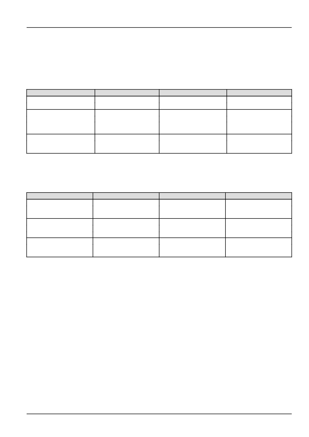
Wheel tread settings
NOTE: Tread settings are measured from center of tire to center of tire.
Front wheel settings
Tire Type
Tractor Model
Setting
NOTE
Agricultural, (R1)
9.5-16
Front-Wheel Drive
1263 mm (49.7 in)
Not Adjustable
Turf, (R3)
Not Adjustable
Front-Wheel Drive
28 x 8.50-15
(Dished In Only)
1209 mm (47.6 in)
Industrial (R4)
Not Adjustable
12 x 16.5
Front-Wheel Drive
1392 mm (54.8 in)
(Dished In Only)
NOTICE: Never attempt to widen the tread setting by reversing front wheels on a front-wheel drive system.
NOTE: Torque front wheel bolts and nuts to: 176 - 196 N·m (130 - 145 lb ft).
Rear wheel settings
Tire Type
Tractor Model
Setting
NOTE
Agricultural, (R1)
1094 - 1266 mm
Adjustable by switching -
13.6-24
Front-Wheel Drive
(43.1 - 49.8 in)
Dish in or dish out
Turf, (R3)
41 x 14.00-20
1135 mm (44.7 in)
Not adjustable
Front-Wheel Drive
(Dish In Only)
Industrial, (R4)
Not adjustable
17.5L x 24
Front-Wheel Drive
1320 mm (52.0 in)
(Dish In Only)
NOTE: Torque rear wheel bolts and nuts to: 176 - 196 N·m (130 - 145 lb ft)
9-1
9 - SPECIFICATIONS
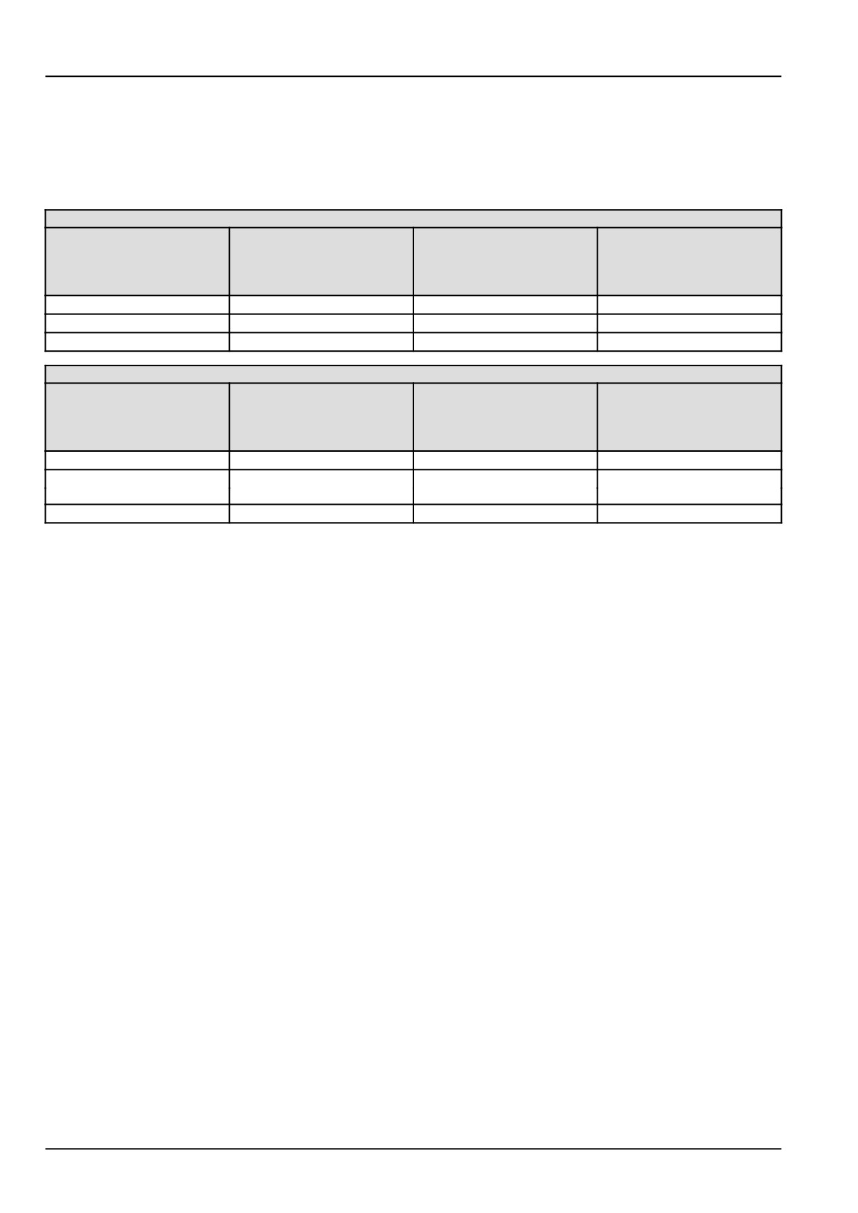
Tire inflation pressures
Tire pressure must be considered when adding weights, implements, or attachments to the tractor or damage to the
tractor may occur.
The chart below outlines tire inflation pressures.
FRONT TIRE INFLATION PRESSURES
Tire Type
Tire Size
Recommended Inflation
Maximum load capacity
Pressures
at
(Minimum inflation
pressure)
Agricultural (R1)
9.5-16, 4PR, R1
55 - 179 kPa (8 - 26 psi)
375 kg (825 lb)
Turf (R3)
28 x 8.50-15, 4PR, R3
55 - 152 kPa (8 - 22 psi)
386 kg (850 lb)
Industrial (R4)
12 x 16.5, 6PR, R4
55 - 221 kPa (8 - 32 psi)
1098 kg (2420 lb)
REAR TIRE INFLATION PRESSURES
Tire Type
Tire Size
Recommended Inflation
Maximum load capacity
Pressures
at
(Minimum inflation
pressure)
Agricultural (R1)
13.6-24, 4PR, R1
83 - 124 kPa (12 - 18 psi)
850 kg (1870 lb)
Turf (R3)
41 x 14.00-20, 4PR, R3
83 - 97 kPa (12 - 14 psi)
825 kg (1819 lb)
Industrial (R4)
17.5L x 24, 6PR, R4
83 - 138 kPa (12 - 20 psi)
2080 kg (4580 lb)
NOTE: Do not under inflate or overinflate tires. Do not exceed maximum inflation pressure listed.
9-2
9 - SPECIFICATIONS
Liquid ballast
Rear tire liquid
Ballast Weights (Per Tire) 600 g/5 lb Gal Solution/CaCl2.
Tire Type
Approximate
Tire Size
Added Weight
Agricultural
13.6-24,
182 kg (400 lb)
4PR, R1
Turf
41 x 14.00-20,
157 kg (346 lb)
4PR, R3
Industrial (R4)
17.5 x 24,
272 kg (600 lb)
6PR, R4
9-3
9 - SPECIFICATIONS
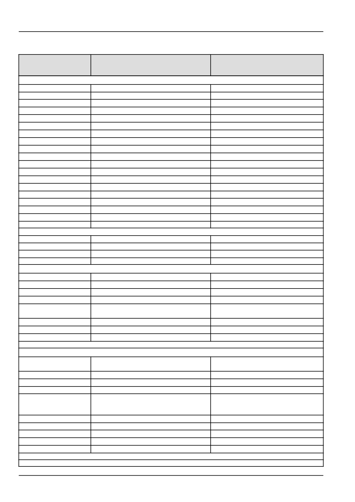
General specifications
Model
Model
- Boomer 41
- Boomer 47
Hydrostatic/Gear
Hydrostatic/Gear
Engine
Type
Diesel
Diesel
Model
N844L-F-30
N844L-F-34
Emission level (tier)
4
4
Aspiration
Natural
Natural
Engine gross horsepower
30 kW (40.2 Hp)
34 kW (45.6 Hp)
Cylinders
4
4
Bore
84 mm (3.3 in)
84 mm (3.3 in)
Stroke
100 mm (3.93 in)
100 mm (3.93 in)
Displacement
2.216 L (135 in³)
2.216 L (135 in³)
Compression ratio
23.3:1
23.3:1
Firing order
1-3-4-2
1-3-4-2
Low idle speed
1000 - 1100 RPM (1000 - 1100 RPM)
1000 - 1100 RPM (1000 - 1100 RPM)
Maximum speed :
High Idle
2800 - 2850 RPM (2800 - 2850 RPM)
2800 - 2850 RPM (2800 - 2850 RPM)
Rated
2600 RPM
2600 RPM
Valve clearance (cold)
Intake
0.2 mm (0.008 in)
0.2 mm (0.008 in)
Exhaust
0.2 mm (0.008 in)
0.2 mm (0.008 in)
Block type
Cast iron
Cast iron
Lubrication
Pressure Feed by oil pump
Pressure Feed by oil pump
Capacities
Fuel tank
40 L (10.5 US gal)
40 L (10.5 US gal)
Cooling system
7.5 L (2.0 US gal)
7.5 L (2.0 US gal)
Engine crankcase:
With Filter
5.7 L (6.0 US qt)
5.7 L (6.0 US qt)
Rear axle & transmission
(Includes hydraulics)
Gear
43.0 L (11.4 US gal)
43.0 L (11.4 US gal)
HST
43.0 L (11.4 US gal)
43.0 L (11.4 US gal)
Front axle
8.0 l (8.4 US qt)
8.0 l (8.4 US qt)
Cooling system
Type
Pressurized liquid with recirculating bypass
Pressurized liquid with recirculating
bypass
Water pump:
Type
Centrifugal
Centrifugal
Drive
V-Belt
V-Belt
Belt deflection
10 - 13 mm (0.4 - 0.5 in) when 10 kg (22 lb)
10 - 13 mm (0.4 - 0.5 in) when 10 kg
pressure is applied midway between belt
(22 lb) pressure is applied midway
pulleys
between belt pulleys
Fan diameter:
405 mm (15.9 in)
405 mm (15.9 in)
Thermostat:
Start to open
82 °C (179.6 °F)
82 °C (179.6 °F)
Fully open
95 °C (203 °F)
95 °C (203 °F)
Radiator cap
90 kPa (13 psi)
90 kPa (13 psi)
9-4
9 - SPECIFICATIONS
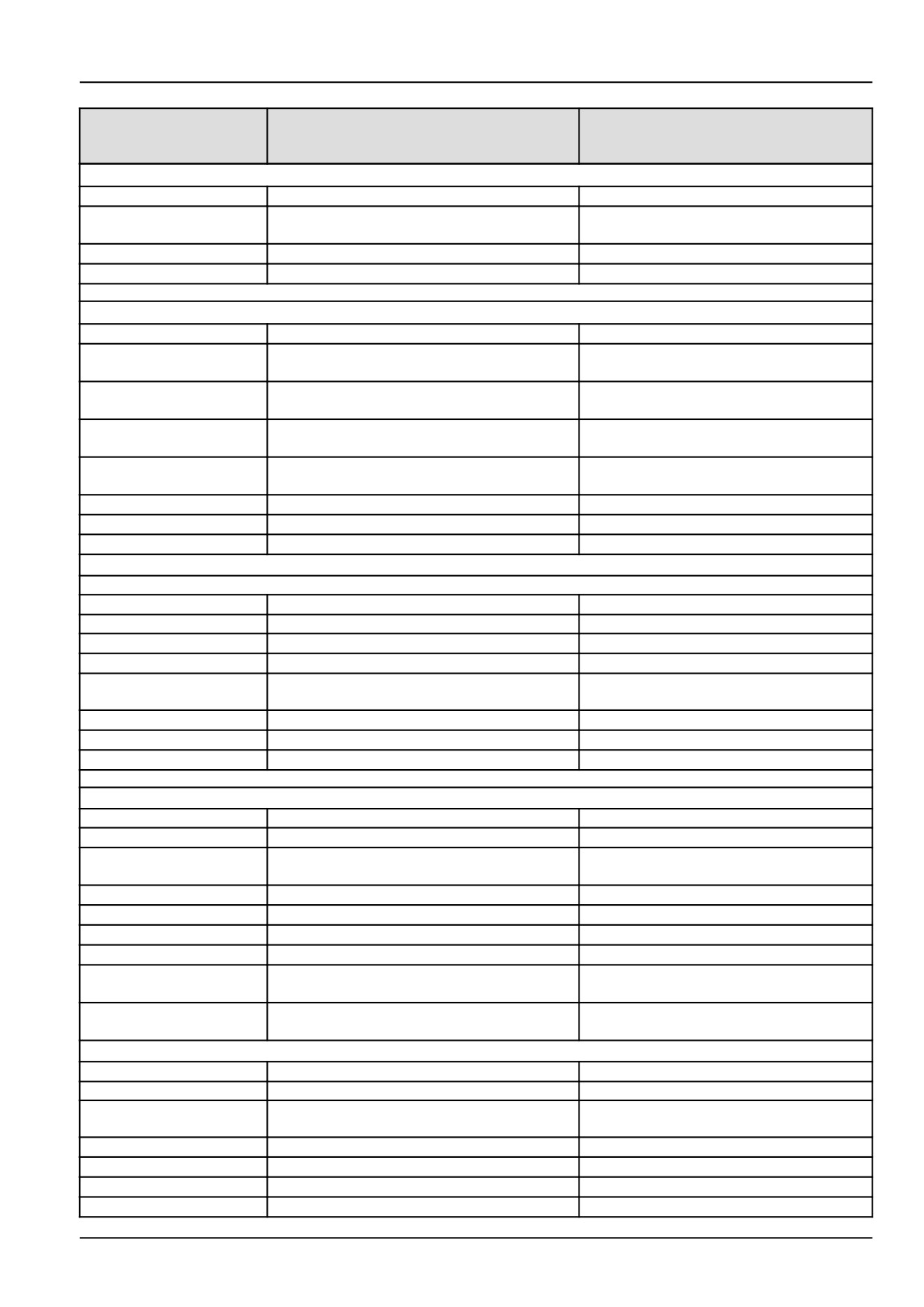
Model
Model
- Boomer 41
- Boomer 47
Hydrostatic/Gear
Hydrostatic/Gear
Electrical system
Alternator:
12 V, Heavy Duty, 85 A
12 V, Heavy Duty, 85 A
Battery:
12 V, w/ negative ground, 80 / 660 cca BCI
12 V, w/ negative ground, 80 / 660 cca
Group 34
BCI Group 34
Starting motor:
Solenoid pre-engaged reduction
Solenoid pre-engaged reduction
Cold - start aid:
Glow plug
Glow plug
Fuel system
Fuel type
Diesel
Diesel
Type of fuel to use if
No. 2-Diesel, Cetane rating: minimum
40
No. 2-Diesel, Cetane rating: minimum 40
above -7 °C (19 °F)
Type of fuel to use if
No. 1-Diesel, Cetane rating: minimum
40
No. 1-Diesel, Cetane rating: minimum 40
below -7 °C (19 °F)
Sulphur content
No. 1-Diesel
0.3 %
(Maximum) :
Sulphur content
No. 2-Diesel
0.3 %
(Maximum) :
Injection pump:
Type:
In-line
In-line
Timing:
16 - 17.5 ° (16 - 17.5 °) BTDC
16 - 17.5 ° (16 - 17.5 °) BTDC
Gear Transmission
Clutch
Type
Dry disc
Dry disc
Number of clutches
1
1
Number of plates
1
1
Material
Organic
Organic
Plate diameter
275 mm (10.8 in) Transmission 12x12
Trans
275 mm (10.8 in) Transmission 12x12
Trans
Plate surface area
33949 mm² (52.6 in²)
33949 mm² (52.6 in²)
Method of operation
Foot-Mechanical
Foot-Mechanical
Pedal : Free-travel
19 - 30 mm (0.75 - 1.2 in)
19 - 30 mm (0.75 - 1.2 in)
HST Transmission
Gear box
Type
HST
HST
Number of range gears
3
3
and speeds
Range synchronization
None
None
Number of gear levers
1
1
Cruise control offering
STD
STD
Cruise control type
Electro - magnetic
Electro - magnetic
High pressure relief valve
37266 kPa (5405 psi)
37266 kPa (5405 psi)
setting
Trans/rear axle oil
43 L (11.4 US gal)
43 L (11.4 US gal)
capacity
Service brake
Type
Wet disc
Wet disc
Actuation
Mechanical
Mechanical
Number of plates - per
2
2
axle
Total number pf Plates
4
4
Disc lining diameter OD
223 mm (8.78 in)
223 mm (8.78 in)
Disc lining diameter ID
174 mm (6.85 in)
174 mm (6.85 in)
Lining type (Material)
Paper
Paper
9-5
9 - SPECIFICATIONS
Model
Model
- Boomer 41
- Boomer 47
Hydrostatic/Gear
Hydrostatic/Gear
Service brake pedal
Yes
Yes
parking lock
Parking Brake
Type
Latch
Latch
Location
Seat side
Seat side
Actuation
Mechanical
Mechanical
Lever latching
Cable activated
Cable activated
Steering
Type
Power
Power
Turns lock-to-lock:
FWD
3.92 L to R
3.92 L to R
3.30 R to L
3.30 R to L
Front wheel
Toe-in
0 - 5 mm (0 - 0.20 in)
0 - 5 mm (0 - 0.20 in)
Turning radius w/o brakes:
FWD
3462 mm (136 in) Left turn
3462 mm (136 in) Left turn
3462 mm (136 in) Right turn
3462 mm (136 in). Right turn
Steering system relief
145 Kg/cm² (2062 psi)
145 Kg/cm² (2062 psi)
valve setting
Maximum pump flow
15.9 L/min (4.20 US gpm) Gear,
15.9 L/min (4.20 US gpm) Gear,
19.9 L/min (5.3 US gpm) HST
19.9 L/min (5.3 US gpm) HST
Power Take - Off (Rear)
Type
Independent
Independent
Clutch type
Wet disc
Wet disc
Clutch material asbestos
Yes
Yes
free (Yes or No)
Number of plates
7
7
Plate diameter
90.0 mm (3.5 in)
90.0 mm (3.5 in)
Plate surface area
3145.0 mm² (4.9 in²)
3145.0 mm² (4.9 in²)
Actuation
Switch
Switch
Master shield type (Fixed
Flip up
Flip up
or Flip up
Number of splines
6
6
Shaft size:
35 mm (1.4 in)
35 mm (1.4 in)
Engine Speed for
2409 RPM - HST Transmission
2409 RPM - HST Transmission
540 RPM Rear PTO
2409 RPM - Gear Transmission
2409 RPM - Gear Transmission
Operation
PTO Horsepower
22.1 kW (29.8 Hp) - HST
26.1 kW (35.0 Hp) - HST
observed
23.5 kW (31.6 Hp) - Gear
27.8 kW (37.3 Hp) Gear
Mid PTO (optional)
Type
Independent
Independent
Clutch type
Wet disc
Wet disc
Number of plates
7
7
Actuation
Manual lever
Manual lever
Direction of rotation (As
Clockwise
Clockwise
viewed from rear of
tractor)
9-6
9 - SPECIFICATIONS
Model
Model
- Boomer 41
- Boomer 47
Hydrostatic/Gear
Hydrostatic/Gear
Number of splines
15
15
Shaft size:
25.0 mm (1.0 in)
25.0 mm (1.0 in)
Engine speed for
2563 RPM - HST Transmission
2563 RPM - HST Transmission
2000 RPM Mid PTO
2563 RPM - Gear Transmission
2563 RPM - Gear Transmission
operation
Hydraulic lift system
Type
Open center
Open center
Pump type
Gear
Gear
Pump capacity at full
33.3 L/min (8.8 US gpm) (Gear
throttle
transmission)
29.9 L/min (7.9 US gpm) (HST
transmission)
System relief valve setting
16671 kPa (2418 psi)
16671 kPa (2418 psi)
Pump location
Engine mounted
Engine mounted
Transmission speeds (Hydrostatic)
( 2600 RPM Engine rated speed with
( 2600 RPM Engine rated speed with
12.4-24 Rear tires)
12.4-24 Rear tires)
Gear position:
Low
0 - 4.65 km/h (0 - 2.89 mph)
0 - 4.65 km/h (0 - 2.89 mph)
Mid
0 - 10.49 km/h (0 - 6.52 mph)
0 - 10.49 km/h (0 - 6.52 mph)
High
0 - 24.10 km/h (0 - 14.98 mph)
0 - 24.10 km/h (0 - 14.98 mph)
Reverse low
0 - 4.65 km/h (0 - 2.89 mph)
0 - 4.65 km/h (0 - 2.89 mph)
Reverse mid
0 - 10.49 km/h (0 - 6.52 mph)
0 - 10.49 km/h (0 - 6.52 mph)
Reverse high
0 - 24.10 km/h (0 - 14.98 mph)
0 - 24.10 km/h (0 - 14.98 mph)
Transmission speeds (Gear)
Gear position: forward
Range 1, 1st gear
1.07 km/h (0.067 mph)
1.07 km/h (0.067 mph)
Range 1, 2nd gear
1.27 km/h (0.79 mph)
1.27 km/h (0.79 mph)
Range 1, 3rd gear
1.49 km/h (0.93 mph)
1.49 km/h (0.93 mph)
Range 1, 4th gear
2.00 km/h (1.24 mph)
2.87 km/h (1.78 mph)
Range 2, 1st gear
2.43 km/h (1.51 mph)
2.43 km/h (1.51 mph)
Range 2, 2nd gear
2.88 km/h (1.79 mph)
2.88 km/h (1.79 mph)
Range 2, 3rd gear
3.38 km/h (2.10 mph)
3.38 km/h (2.10 mph)
Range 2, 4th gear
4.53 km/h (2.82 mph)
4.53 km/h (2.82 mph)
Range 3, 1st gear
5.37 km/h (3.33 mph)
5.37 km/h (3.33 mph)
Range 3, 2nd gear
6.36 km/h (3.95 mph)
6.36 km/h (3.95 mph)
Range 3, 3rd gear
7.48 km/h (4.65 mph)
7.48 km/h (4.65 mph)
Range 3, 4th gear
10.02 km/h (6.22 mph)
10.02 km/h (6.22 mph)
Range 4, 1st gear
13.89 km/h (8.63 mph)
13.89 km/h (8.63 mph)
Range 4, 2nd gear
16.47 km/h (10.24 mph)
16.47 km/h (10.24 mph)
Range 4, 3rd gear
19.36 km/h (12.03 mph)
19.36 km/h (12.03 mph)
Range 4, 4th gear
25.93 km/h (16.11 mph)
25.93 km/h (16.11 mph)
Gear Position: Reverse
Range 1, 1st gear
0.97 km/h (0.60 mph)
0.97 km/h (0.60 mph)
Range 1, 2nd gear
1.15 km/h (0.72 mph)
1.15 km/h (0.72 mph)
Range 1, 3rd gear
1.36 km/h (0.84 mph)
1.36 km/h (0.84 mph)
Range 1, 4th gear
1.82 km/h (1.13 mph)
1.82 km/h (1.13 mph)
Range 2, 1st gear
2.20 km/h (1.37 mph)
2.20 km/h (1.37 mph)
Range 2, 2nd gear
2.61 km/h (1.62 mph)
2.61 km/h (1.62 mph)
Range 2, 3rd gear
3.07 km/h (1.91 mph)
3.07 km/h (1.91 mph)
9-7
9 - SPECIFICATIONS
Model
Model
- Boomer 41
- Boomer 47
Hydrostatic/Gear
Hydrostatic/Gear
Range 2, 4th gear
4.11 km/h (2.56 mph)
4.11 km/h (2.56 mph)
Range 3, 1st gear
4.87 km/h (3.03 mph)
4.87 km/h (3.03 mph)
Range 3, 2nd gear
5.78 km/h (3.59 mph)
5.78 km/h (3.59 mph)
Range 3,, 3rd gear
6.79 km/h (4.22 mph)
6.79 km/h (4.22 mph)
Range 3, 4th gear
9.09 km/h (5.65 mph)
9.09 km/h (5.65 mph)
Range 4, 1st gear
12.61 km/h (7.83 mph)
12.61 km/h (7.83 mph)
Range 4, 2nd gear
14.95 km/h (9.29 mph)
14.95 km/h (9.29 mph)
Range 4, 3rd gear
17.57 km/h (10.92 mph)
17.57 km/h (10.92 mph)
Range 4, 4th gear
23.53 km/h (14.62 mph)
23.53 km/h (14.62 mph)
CAST IRON WEIGHTS
Front End:
With weight extension
(5) weights @ 26 kg (60 lb) each
(5) weights @ 26 kg (60 lb) each
bracket installed
With weight extension
Optional (3) weights @ 45 kg (100 lb) each
Optional (3) weights @ 45 kg (100 lb)
bracket installed
each
Rear Wheel:
Ag. Tires
(4) weights (2) per wheel @ 45 kg (100 lb)
(4) weights (2) per wheel @ 45 kg
each
(100 lb) each
Turf Tires
NA
NA
R-4 Tires
(4) weights (2) per wheel @ 45 kg
(4) weights (2) per wheel @ 45 kg
(100 lb)each
(100 lb)each
Drawbars
Adjustable
Standard
Standard
Tires
Front :
Agricultural:
13.6 x 24, R1
13.6 x 24, R1
Turf:
28 x 8.50 - 15 TL, R3
28 x 8.50 - 15 TL, R3
Industrial:
12-16.5 6PR TL, R4
12-16.5 6PR TL, R4
Rear :
Agricultural
13.6 x 24 , 4PR, R1
13.6 x 24 , 4PR, R1
Turf
41 x 14.00-20, 4PR, R3
41 x 14.00-20, 4PR, R3
Industrial
17.5L X 24. 6PR TL, R4
17.5L X 24. 6PR TL, R4
Wheel bolt torques
Front wheel ---
Disc-to-Hub:
FWD
176 - 196 N·m (130 - 145 lb ft)
176 - 196 N·m (130 - 145 lb ft)
Rear Wheel --- Disc-to
176 - 196 N·m (130 - 145 lb ft)
176 - 196 N·m (130 - 145 lb ft)
Axle
ROPS attaching bolt torques
ROPS to rear axle
132 - 147 N·m (97 - 108 lb ft)
132 - 147 N·m (97 - 108 lb ft)
Seat belt
49 - 54 N·m (36 - 40 lb ft)
49 - 54 N·m (36 - 40 lb ft)
9-8
9 - SPECIFICATIONS
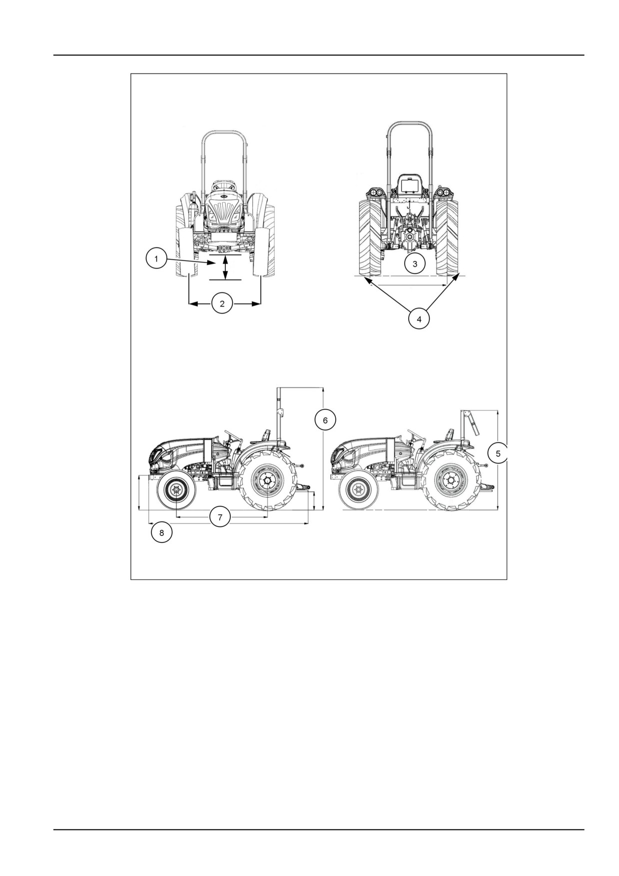
Tractor dimensions
Boomer 41
Boomer 47
(1) - MINIMUM GROUND CLEARANCE (under drawbar):
Ag. Tires:
13.6 - 24
363 mm (14.3 in)
363 mm (14.3 in)
Turf Tires:
286.5 mm (11.3 in)
286.5 mm (11.3 in)
41 x 14.00-20
Ind. Tires:
423 mm (16.7 in)
423 mm (16.7 in)
17.5L x 24 6PR
WHEEL TREAD SETTINGS:
(2)-FRONT:
Ag. Tires:
9.5 x 16 4 PR
1266 mm (49.7 in)
1266 mm (49.7 in)
Turf Tires:
28 x 8.50-14 4 PR (Dished In Only)
1209 mm (50.0 in)
1209 mm (50.0 in)
Ind. Tires:
12 x 16.5 6PR (Dished In Only)
1386 mm (54.6 in)
1386 mm (54.6 in)
(3)-REAR:
Ag. Tires:
13.6-24 4 PR
1094 - 1266 mm (43.1 -
49.8 in)
1094 - 1266 mm (43.1 -
49.8 in)
Turf Tires:
41 x 14.00-20
1266 mm (49.8 in)
1266 mm (49.8 in)
Ind. Tires
17.5 L x 24 6PR
1320 mm (52.0 in)
1320 mm (52.0 in)
(Dished In Only)
(4) - WIDTH:
Rear Axle - Outside to Outside of tire:
Ag. Tires:
1608 mm (63.3 in)
1608 mm (63.3 in)
13.6-24 (Dished Out)
Turf Tires:
1618 mm (63.7 in)
1618 mm (63.7 in)
41 x 14.00-20 (Dished Out)
Ind. Tires:
1754 mm (69.1 in)
1754 mm (69.1 in)
17.5L x 24 (Dish In)
(5) - Top of ROPS - Folding: Down position
Ag. Tires:
13.6 - 24
Down Position
1936 mm (76.2 in)
1936 mm (76.2 in)
Turf Tires:
41 x 14.00-20
Down Position
1860 mm (73.2 in)
1860 mm (73.2 in)
Ind. Tires:
17.5 x 24 6PR
Down Position
1996 mm (78.6 in)
1996 mm (78.6 in)
(6) - Top of ROPS - Folding: Up position
Ag. Tires:
13.6 - 24
Up Position
2407 mm (94.8 in)
2407 mm (94.8 in)
Turf Tires:
41 x 14.00-20
Up Position
2331 mm (91.8 in)
2331 mm (91.8 in)
Ind. Tires:
17.5L x 24 6 PR
Up Position
2467 mm (97.1 in)
2467 mm (97.1 in)
9-9

9 - SPECIFICATIONS
Boomer 41
Boomer 47
(7) - WHEEL BASE:
FWD
1858 mm (73.2 in)
1858 mm (73.2 in)
(8) - LENGTH:
FWD:
3253 mm (128.1 in)
3253 mm (128.1 in)
WEIGHT With ROPS / less tires:
HST (FWD)
1583 kg (3490 lb)
1583 kg (3490 lb)
GEAR (FWD)
1553 kg (3424 lb)
1553 kg (3424 lb)
9-10
9 - SPECIFICATIONS
NHIL13CT01346HA
1
9-11
10 - ACCESSORIES
10 - ACCESSORIES###_10_###
Optional equipment
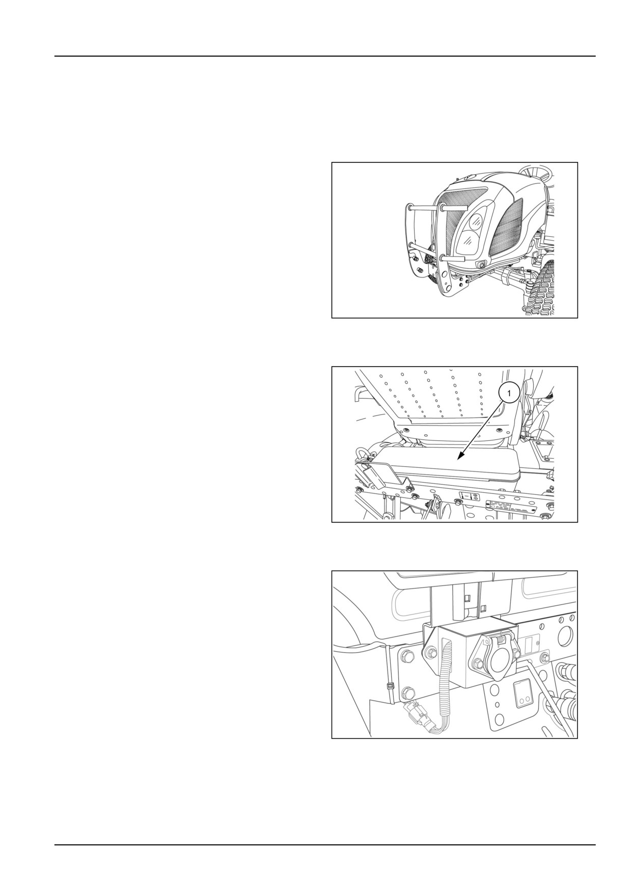
Grille guard
An optional pivoting front grille guard provides protection
to the front of the tractor. The grille guard is compati-
ble with a front end loader or a maximum of three 27 kg
(60 lb) weights with front weight bracket.
NHIL13CT01277AA
1
Tool box
The tool box (1) is an optional attachment and is located
behind the seat and between the ROPS uprights.
NHIL13CT01073AA
2
Trailer electrical socket
A 7-pin trailer socket is an optional attachment and is lo-
cated behind the seat on the left side of the ROPS cross-
brace.
93103752
3
10-1
11 - FORMS AND DECLARATIONS
Delivery report - owner copy
Check and adjust as required
Boomer 41, Boomer 47
Inoperative service checks
Safety items check
1.
Tire Pressure
1.
Seat Belts Installed
2.
Seat Belt Bolt Torque - 54 N·m (40 lb ft)
2.
Air Cleaner Element & Hose Connections
3.
PTO Shield Installed
4.
SMV Emblem Installed
3.
Radiator Coolant Level
5.
Safety Decals Installed
6.
Neutral Start Switches Operation
4.
Fan Belt Tension
7.
Park Brake Operation
8.
Flashing Lights/Tail Lights Operation
5.
Battery Cleanliness, Vent Openings,
9.
Operator's Manual (present)
Electrolyte Level, & Charge
6.
Engine Oil Level
Operative service checks
7.
Transmission & Rear Axle Oil Level
All operating checks are to be performed with tractor at
normal operating temperature.
8.
Front Axle & Final Reduction
Gear Case Oil Level (FWD)
1.
Lights & Instruments for Proper Operation
& Fuel Shut Down with Key Switch Off
9.
Hydraulic Lift Control Drop Rate Adjustment
2.
Fluid & Oil Leaks
10.
Top Link (present)
3.
Maximum No-load High & Idle Speed
11.
Brake Adjustment
Adjustments
Boomer 33/37 - (Max: 2800 RPM, Idle: 970
12.
Wheel Bolt Torque -
RPM)
Front and Rear 176 - 196 N·m (130 - 145 lb ft)
4.
PTO Engagement & Disengagement
13.
Front Wheel Toe-in
5.
Selector Lever for HPL Control
14.
Fuel Level
6.
FWD-Drive Lever Operation
15.
Seat Function
7.
Operation of HST
8.
Explain safe operation of (DPF) emission system
Dealer Representative's
Date
Signature
"I have been instructed in the operation, maintenance, and safety features of this machine as detailed in the
operator's manual."
Owner's Signature
Date
11-3
11 - FORMS AND DECLARATIONS
Delivery report - dealer copy
Check and adjust as required
Boomer 41, Boomer 47
Inoperative service checks
Safety items check
1.
Tire Pressure
1.
Seat Belts Installed
2.
Seat Belt Bolt Torque - 54 N·m (40 lb ft)
2.
Air Cleaner Element & Hose Connections
3.
PTO Shield Installed
4.
SMV Emblem Installed
3.
Radiator Coolant Level
5.
Safety Decals Installed
6.
Neutral Start Switches Operation
4.
Fan Belt Tension
7.
Park Brake Operation
8.
Flashing Lights/Tail Lights Operation
5.
Battery Cleanliness, Vent Openings,
9.
Operator's Manual (present)
Electrolyte Level, & Charge
6.
Engine Oil Level
Operative service checks
7.
Transmission & Rear Axle Oil Level
All operating checks are to be performed with tractor at
normal operating temperature.
8.
Front Axle & Final Reduction
Gear Case Oil Level (FWD)
1.
Lights & Instruments for Proper Operation
& Fuel Shut Down with Key Switch Off
9.
Hydraulic Lift Control Drop Rate Adjustment
2.
Fluid & Oil Leaks
10.
Top Link (present)
3.
Maximum No-load High & Idle Speed
11.
Brake Adjustment
Adjustments
Boomer 33/37 - (Max: 2800 RPM, Idle: 970
12.
Wheel Bolt Torque -
RPM)
Front and Rear 176 - 196 N·m (130 - 145 lb ft)
4.
PTO Engagement & Disengagement
13.
Front Wheel Toe-in
5.
Selector Lever for HPL Control
14.
Fuel Level
6.
FWD-Drive Lever Operation
15.
Seat Function
7.
Operation of HST
8.
Explain safe operation of (DPF) emission system
Dealer Representative's
Date
Signature
"I have been instructed in the operation, maintenance, and safety features of this machine as detailed in the
operator's manual."
Owner's Signature
Date
11-5