New Holland TD 60D, TD 70D, TD 80D, TD 90D, TD 95D Tractor. OPERATOR’S MANUAL - page 4
SECTION 4
LUBRICATION AND MAINTENANCE
INTRODUCTION
Before connecting external cylinders, make sure that
the oil inside is clean, that it has not deteriorated after
prolonged storage and that it is of the type specified.
This section gives full details of the maintenance
To prevent dirt entering, clean the lubricating fittings
procedures required to keep your tractor in optimal
before lubrication. Clean excess lubricant from the
working conditions. The lubrication and maintenance
fittings after lubrication.
table on pages 4--5 and 4--6 can be used for rapid
reference for this purpose. All operations are
numbered to facilitate use.
MAINTENANCE INTERVALS
In addition to the normal maintenance operations
The intervals suggested in the lubrication and
listed, the following parts must be checked during
maintenance table are those to be followed under
flexible maintenance or during the first 50 hours of
normal working conditions.
operation:
Intervals should be in line with working and
• Wheel nut tightness;
environmental conditions. The intervals should be
shortened in adverse working conditions (wet, mud,
• Oil levels in hub and front axle casing
-
sand, high dust levels).
four--wheel drive only.
LUBRICATION AND MAINTENANCE
WARNING
TABLES -- Pages 4--5 and 4--6
Park the tractor on level ground and, where possible,
ensure all hydraulic cylinders are fully extended
The tables list the intervals at which routine checks,
before checking oil levels.
lubrication, maintenance and/or adjustments should be
carried out. Use the table as a quick reference guide
when carrying out maintenance on the tractor. The
SAFETY PRECAUTIONS
operations follow the order in the table.
Read and follow all the safety precautions listed in
RUNNING--IN PERIOD
“Tractor maintenance”, in section 1.
During the running--in period (approximately 50 hours
NOTE: Dispose of any filters and liquids used in an
of work), in addition to carrying out the operations
appropriate and with respect to the environment.
indicated in section 9 -- ‘First 50 Hours Service’, we
recommend the following:
CAUTION
• Run the engine for a few minutes at low speeds
Do not carry out any inspections, lubrication,
and let it idle after every cold start;
maintenance or adjustments on the tractor with the
engine running.
• Do not let the engine run at minimum speeds for
a long time;
HOW TO PREVENT CONTAMINATION OF
• Do not use the tractor continuously for heavy
THE SYSTEM
work;
To avoid contamination when changing oil, filters, etc.,
• Follow the above recommendations after
always clean the area around the fill points, inspection
replacement of major parts.
and drain plugs, dipsticks and filters.
4--1
SECTION 4 -- LUBRICATION AND MAINTENANCE
CAUTION
CAUTION
After the first 50 hours of work, replace the oil in the
Carry out the operations illustrated in this section at
sump (operation no. 27) together with the relevant
the specified intervals to ensure that your tractor
filter (operation no. 31) and the oil filter cartridge for
functions properly. Remember, however, to carry out
the hydraulic lift (operation no. 30).
inspections and adjustments as and when
experience and common sense dictates, (frequency
can vary depending on working and environmental
conditions).
TRACTOR REFUELLING
CAUTION
FUEL STORAGE
When using diesel fuel, pay attention to the following:
Take all necessary precautions to ensure that stored
Do not smoke when near diesel fuel. Under no
fuel is not contaminated by dirt, water or any other
circumstances must petrol, alcohol, or a mixture of
substance.
diesel or alcohol be added to the diesel, as it increases
the risk of fire or explosion considerably. In a closed
container, such as a jerry can, they are more explosive
• Store fuel in black iron drums, not zinc drums as
than pure petrol. Do not use these mixtures.
the zinc coating reacts with the fuel and forms
Furthermore, a mixture of diesel and alcohol is not
compounds which contaminate the injection
recommended as it does not lubricate the fuel injection
pump and injectors.
system adequately. Clean the area around the filler
cap and keep it clean. Fill the tank at the end of every
• Protect the storage drums from direct sunlight
day to reduce overnight condensation. Never
and tilt them slightly so that sediment inside can
remove the cap or add fuel when the engine is
be removed through a suitable drainage point.
running. While the tank is being filled, keep control of
the filler nozzle. Do not fill the tank completely. Leave
• To facilitate removal of damp and sediment, fit a
room for an expansion. If the filler cap is lost, replace
drainage plug at the lowest point on the opposite
it with a genuine cap and screw it on tight. Mop up any
end to the outlet pipe.
fuel spillage immediately.
• If the fuel is not filtered from the storage drum,
use a funnel with a fine mesh filter when pouring
the fuel into the tractor tank.
• Organise your fuel purchases so that summer
FUEL SPECIFICATIONS
fuel is not kept for too long and then used in
winter.
The quality of fuel used is an important factor for the
engine’s subsequent performance and satisfactory
REFUELLING
service life. Fuel must be clean, properly refined and
must not corrode the fuel system parts. Ensure that
Before refuelling, clean the area around the tank fill
good quality fuel is used from a reliable source.
point to prevent foreign matter entering the tank.
After refuelling replace the cap and tighten it fully.
NOTE: The fuel tank holds 92 litres ( 24.3 U.S. gal.)
NOTE: If the fuel tank cap should be lost or damaged,
replace it with a genuine replacement part.
4--2
SECTION 4 -- LUBRICATION AND MAINTENANCE
MISCELLANEOUS CHECKS
ENGINE COOLING SYSTEM
Check the following components regularly and, if any
It is advisable to replace the coolant every two years
faults are detected, contact your dealer and replace
or 1200 hours of service, whichever occurs first.
the damaged parts as necessary:
• Steering linkage ball joints: check that there is no
RADIATOR
play in the ball joints and that the conical ends are
securely in place; also check that no grease is
If the cooling circuit is to work properly, it is important
escaping from the protective covers to the ball
that the radiator fins are not clogged.
joints and that the covers themselves are in good
Clean them regularly, even several times a day if the
condition and not cracked;
environment in which you are working is particularly
dusty.
• Hydrostatic steering cylinder lines: the lines must
not show any signs of crimping, cracking or
swelling of the external sheath and likewise there
TYRES
must be no traces of oil between the pipe and the
connector;
Always fit and remove tyres in perfectly clean
conditions. Avoid working in soil. To help when fitting
• Handbrake lever: check that the ratchet locks
or removing tyres, never use grease as a lubricant.
securely.
Use a soap and water solution instead.
When fitting a new or used tyre, inflate it to 3.5 bar
(kg/cm2) (50 Psi) to ensure the correct positioning of
WARNING LIGHTS
the bead. Then inflate the tyre to its service pressure.
Your tractor is fitted with warning lights to inform you
of the operational condition of your tractor. Some of
TYRE PRESSURES
these signal faults which should be corrected
immediately, e.g.: engine oil level, brake fluid level,
Tyre pressures are given in section 3. Remember
coolant level, windscreen wash liquid, air filter
that the values given may differ depending on the
clogging, etc.
following factors: tyres different from those fitted by
the manufacturer, tractor ballast type, different
conditions of use, etc. The tyre manufacturer should
FUEL INJECTION PUMP
be able to provide information concerning the most
suitable pressures.
During the warranty period, any work carried out on
the injection pump must be carried out exclusively by
Do not forget to check the tyre working pressures
your local dealer. If the seal on the fuel pump is
regularly. The frequency of such inspection will vary
removed, the Company cannot be held responsible
depending on operational and climatic conditions.
under the terms of the warranty.
ENVIRONMENTAL CONSIDERATIONS
When it is necessary to refill the fuel tank, or top up
or change the oil, always place a container under the
component to collect any spillage. The products
used are pollutants and we must therefore prevent
them from contaminating the environment in which
we live.
4--3
SECTION 4 -- LUBRICATION AND MAINTENANCE
ACCESS FOR
INSPECTION AND MAINTENANCE
INTRODUCTION
To access the engine components and carry out
inspection, lubrication and maintenance operations,
the bonnet (hood) must be opened.
The following instructions describe the procedure to
be followed.
1
BONNET (HOOD)
1
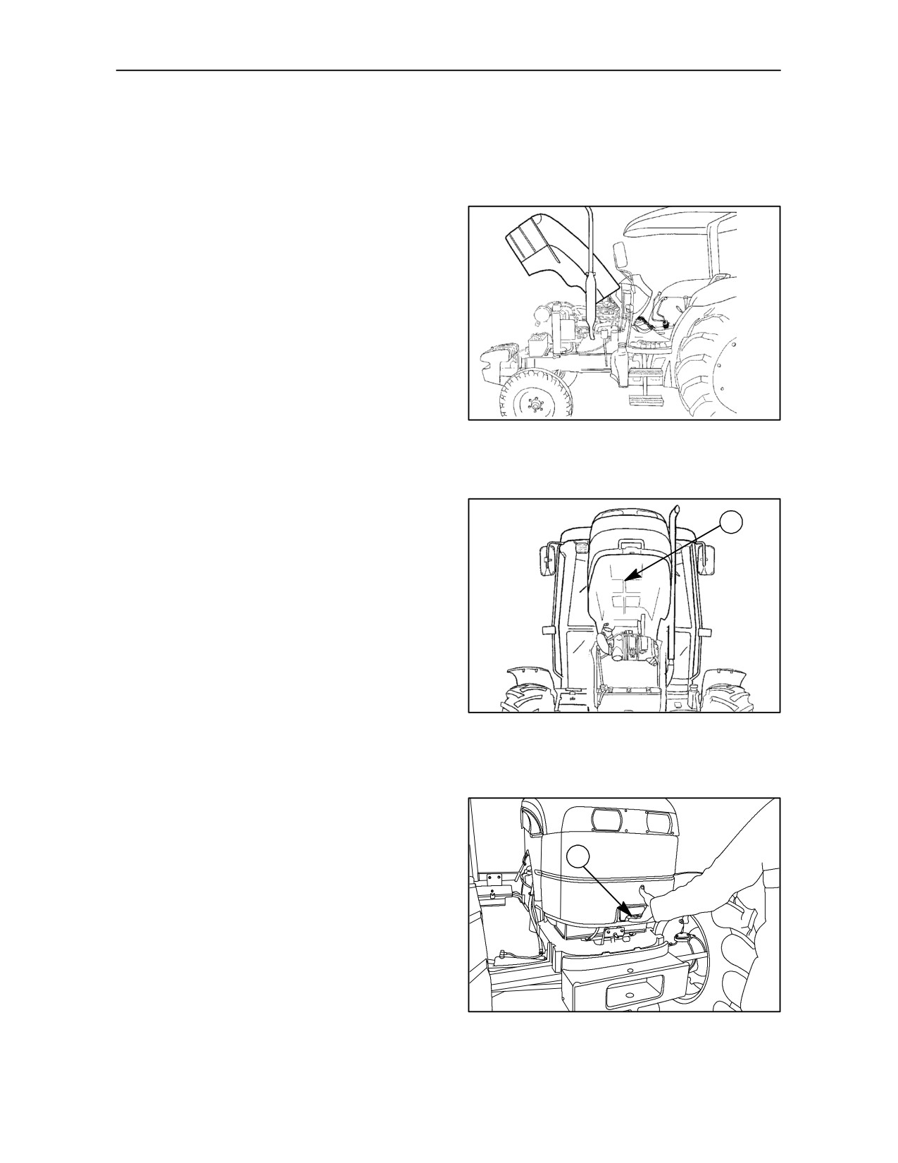
The bonnet is hinged at the rear to allow easy and
safe access to the various engine components.
One gas strut (1) fig. 2 holds the engine bonnet in
one of the two possible positions.
TRE0046A
2
OPENING THE BONNET (HOOD)
Pull the lever upwards (1) fig. 3, lift from the front, and
allow the bonnet to raise. The gas strut (1) fig. 2 will
1
maintain the bonnet in the raised position.
NOTE: To close the bonnet, simply pull it down and
press the top lightly to ensure it engages.
TRE0828A
3
4--4
SECTION 4 -- LUBRICATION AND MAINTENANCE
LUBRICATION AND MAINTENANCE TABLE
The numbers in the second column are with reference to the operations and illustrations in the following pages
of this section.
Maintenance operation
1
Engine clutch
F
4--7
2
Brake pedal
F
4--7
Flexible
3
Fan belt
F
4--8
maintenance
4
Air conditioner compressor belt
F
4--8
5
Outlet valve, dry air filter
F
4--9
6
Main cartridge, dry air filter
F
4--9
With
warni
ng
7
Brake fluid reservoir
F
F
4--10
light ON
8
Fuel sedimenter (condensation drain)
F
4--10
9
Engine oil
F
F
4--10
10
Battery
F
F
4--11
11
Hydrostatic steering reservoir
F
F
4--12
12
Radiator expansion tank
F
F
4--12
Every 10
13
Windscreen washer bottle
F
F
4--12
hours
14
Cab air filter
F
4--13
15
Air conditioner condenser
F
4--13
16
Cab air--conditioning system
F
4--14
17
Oil bath air cleaner
F
F
F
4--15
18
Hydraulic lift and linkage
F
4--16
19
Steering cylinders 4WD
F
4--16
20
Front axle rear pivot 4WD
F
4--16
21
Front axle front pivot 4WD
F
4--17
Every 5
0
22
Steering cylinder 2WD
F
4--17
hours
23
Right hand stub axle 2WD
F
4--17
24
Left--hand stub axle 2WD
F
4--18
25
Front axle pivot 2WD
F
4--18
26
Fuel filter (condensation drain)
F
4--18
4--5
SECTION 4 -- LUBRICATION AND MAINTENANCE
Maintenance operations
27
Engine oil
F
4--19
28
Fuel filter
F
4--19
29
Fuel pump filter
F
4--19
30
Oil filter, hydraulic lift
F
4--20
31
Engine oil filter
F
4--20
32
Oil filter, hydrostatic steering (separate tank)
F
4--20
33
Final reduction gears
F
4--21
Every 300
34
Dry air filter (external cartridge)
F
4--21
hours
35
Rear transmission and hydraulic lift
F
F
4--21
36
Front axle housing 4WD
F
F
4--22
37
Handbrake
F
F
4--22
38
Front axle reduction hubs 4WD
F
F
4--23
39
Front wheels 2WD
F
4--23
40
Front axle swivel bearings 4WD
F
4--23
41
Oil bath air cleaner
F
4--24
Every 600
42
Fuel sedimenter
F
4--24
hours
Every 900
43
Engine valves
F
F
4--24
hours
44
Cab air filter
F
4--25
45
Dry air filter (cartridges: internal and external)
F
4--25
Every 1200
hours or
46
Fuel tank
F
4--25
annually
47
Hydrostatic steering oil (independent tank)
F
4--26
48
Drive shaft sleeve for 4WD front axle connection
F
F
4--26
49
Injectors
F
F
4--27
50
Front axle housing oil, 4WD
F
4--27
Every 1200
51
Front axle final drive hubs oil, 4WD
F
4--27
hours or
every 2
52
Engine cooling system
F
F
4--28
years
53
Transmission and hydraulic oil
F
4--30
54
Final reduction oil
F
4--30
Bleeding the fuel system
4--31
Bleeding the hydraulic brake system
4--31
General
Electrical system
4--33
maintenance
Bodywork maintenance
4--40
Lubrication capacities and specifications
4--41
4--6
SECTION 4 -- LUBRICATION AND MAINTENANCE
FLEXIBLE MAINTENANCE
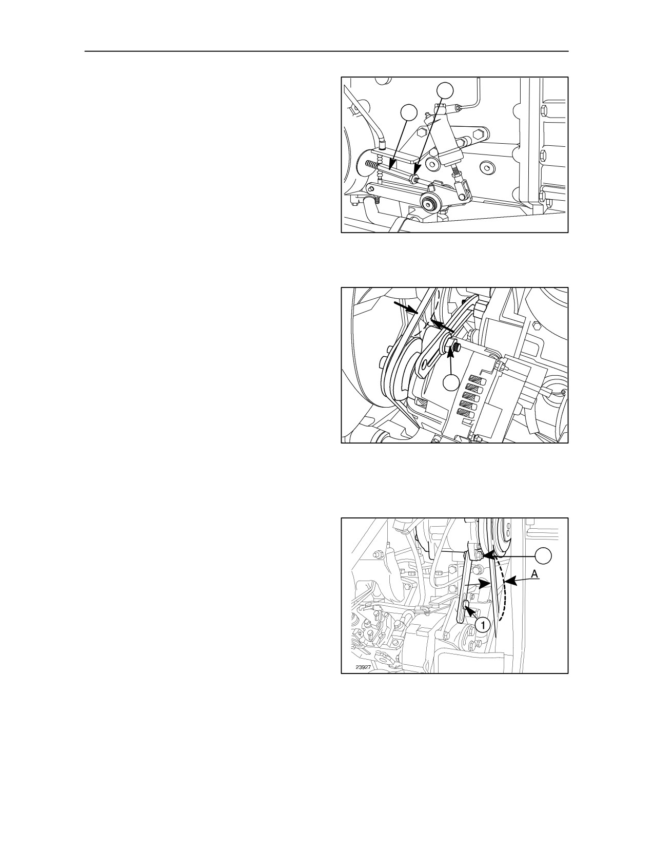
OPERATION 1
1
CLUTCH ADJUSTMENT -- Figs. 1 and 2
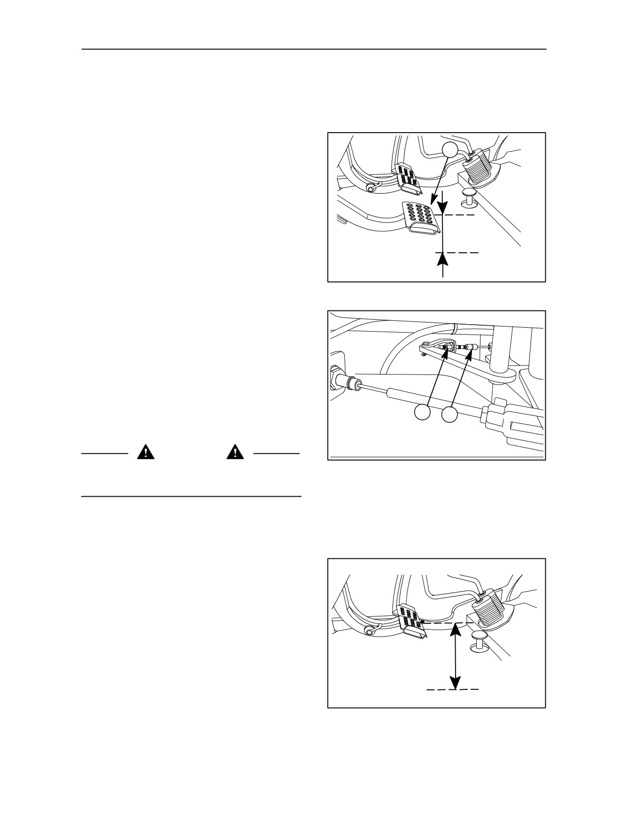
If the clutch pedal position is uncomfortable (too
high) or it will not reach its upper rest position (to
prevent the clutch slipping) check that distance A, on
A
clutch pedal (1) fig. 1 is 35--40 mm (1.4--1.6 in) if not,
adjust the pedal as follows:
--
Release lock nuts (1) fig. 2 and turn hexagon
1
sleeve (2) anti--clockwise;
--
Check that distance A corresponds with the
value given above;
--
Tighten lock nuts (1) fig. 2;
--
Re--check that the pedal travel is as specified.
1
2
CAUTION
2
The distance must be measured from the pedal
centre as shown in fig. 1.
OPERATION 2
BRAKE PEDAL ADJUSTMENT -- Fig. 3-- 4
Adjusting height of service brake pedals
--
With the brake pedals connected to their
respective forks and the pedal connecting pin
released, check pedal adjustment.
A
--
Check that pedal free travel (A) is the same for
each pedal and does not exceeds 80 mm.
3
4--7
SECTION 4 -- LUBRICATION AND MAINTENANCE
--
If adjustment is required, fully release the
handbrake (lever down). Slacken the lock nuts
1
(1) and turn the hexagon sleeves (2) until brake
2
pedal free travel is 5 mm. Finally, tighten the lock
nuts (1).
4
OPERATION 3
FAN BELT (ALL VERSIONS WITHOUT
AIR--CONDITIONING) -- Fig. 5
A
Check that tension (A) at the centre of the belt run,
as shown in the figure, is 10--11 mm (0.39--0.43 in)
with
an applied load of
78--98
N
(8--10 kg or 17.7--22.1 lbs).
1
To adjust, slacken screw (1) and reset the tension to
the values indicated above.
NOTE: If the belt is cracked or frequent adjustment
TRE0830A
is necessary, it needs to be replaced.
5
OPERATION 4
COMPRESSOR BELT -- Fig. 6
Check that tension (A) of the belt shown in the figure, is
2
12--13 mm (0.47--0.51 in) with a load of
78--98 N
(8--10 kg or 17.7--22.1 Ibs), measured in the centre of
the belt run, as illustrated in the figure.
To adjust, slacken screw(1) and adjust belt tensioner (2).
NOTE: If the belt is cracked or frequent adjustment
is necessary, it needs to be replaced.
6
4--8
SECTION 4 -- LUBRICATION AND MAINTENANCE
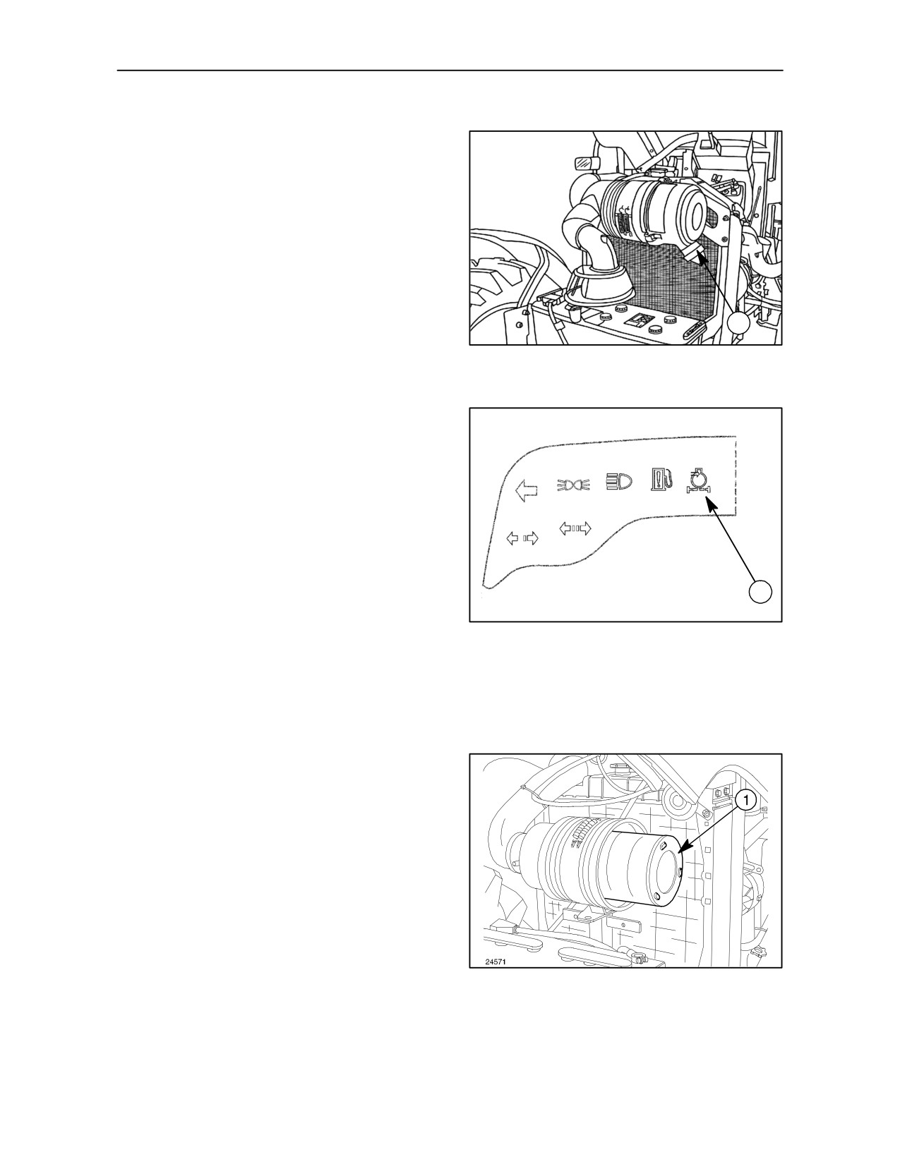
OPERATION 5
AIR FILTER VALVE -- Fig. 7
Check if the outlet valve (1) is clogged by squeezing
the rubber end cap to allow accumulated dust to
escape.
1
7
WHEN THE WARNING LIGHT IS ON
DRY AIR FILTER MAINTENANCE -- Fig. 8
NOTE: Always take corrective action, as follows in
Operation
6, when the red indicator light
(1)
illuminates, indicating that the airflow through the
filter is restricted.
Replace the external element every year, or when pin
holes appear (visible by placing a light inside). Do not
clean the internal safety element (by blowing or
1
washing) but replace annually or whenever the
TRE0073A
external element is replaced.
8
OPERATION 6
MAIN DRY AIR FILTER CARTRIDGE --
Fig. 9
When the red indicator light in the instrument panel
illuminates, remove the cover, extract the outer
element (1) and clean as follows:
--
with a jet of compressed air at less than 5.9 bar
(6 kg/cm2) (85 Psi), insert the air line nozzle
inside the element and blow dust from the inside
through the element to the outside;
or
--
with water and non--foaming detergent, rinse
with a water jet at less than 2.9 bar (3 kg/cm2)
(42 Psi) and dry with dry air at a temperature of
less than 50_C. Do not re--install the element
unless it is perfectly dry. A damp air cleaner
element will rupture when the engine is started.
Never clean the element by tapping it on a hard
9
surface. Instead, tap it on the palm of your hand.
Clean the whole of the inside of the container
carefully with a damp cloth.
Do not disturb the inner safety element.
4--9
SECTION 4 -- LUBRICATION AND MAINTENANCE
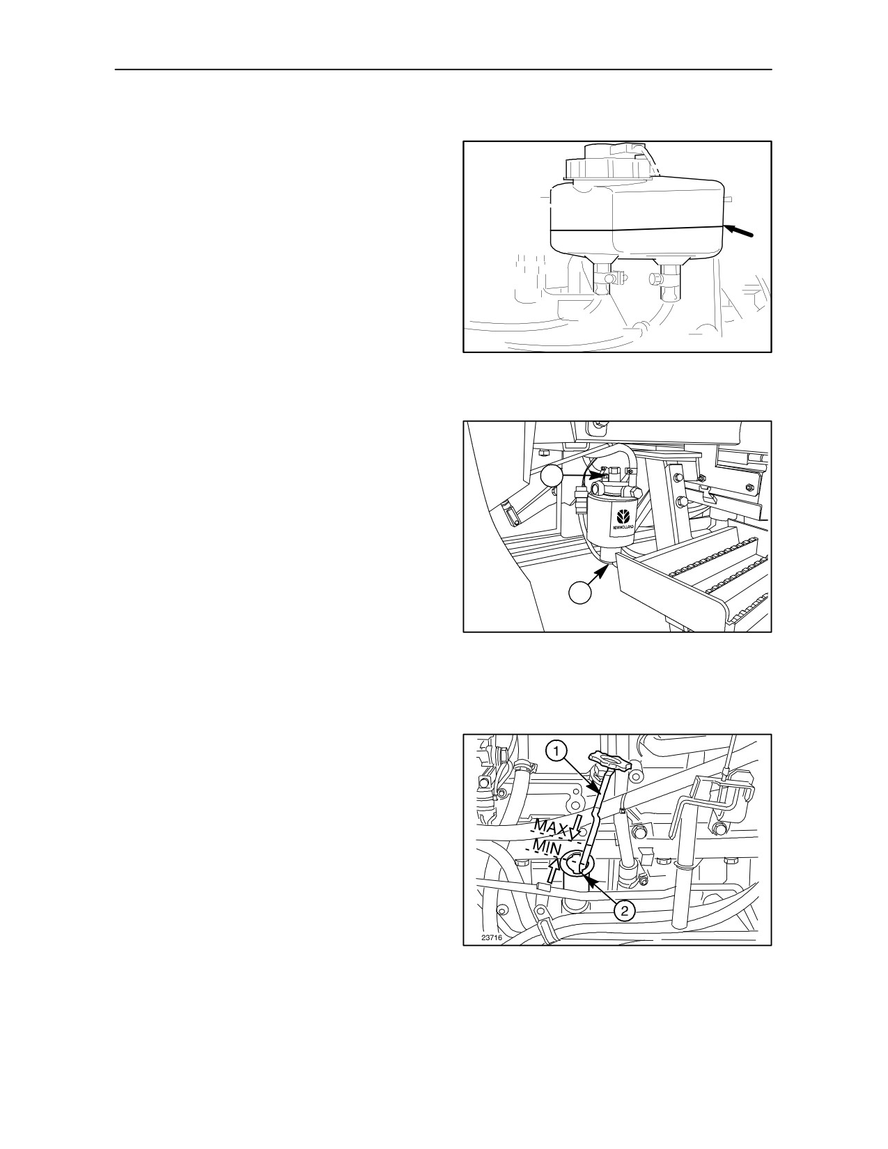
OPERATION 7
BRAKE FLUID LEVEL -- Fig. 10
Check that the fluid level is not below the indicator
arrow on the reservoir. Top up as necessary.
10
OPERATION 8
FUEL SEDIMENTER -- Fig. 11
With the reservoir completely full, partially unscrew
the drain plug (1) until all the water is drained off.
2
To ensure complete discharge, also unscrew the
bleed screw (2). Tighten screw (1) when the fuel
coming out no longer contains air bubbles, then
tighten screw (2).
1
TRE0831A
11
EVERY
10
HOURS
OPERATION 9
ENGINE OIL LEVEL -- Fig. 12 and 13
Check the level with the tractor on a level surface with
the engine switched off. Allow at least five minutes for
the oil to settle in the sump:
--
Remove dipstick (1) fig. 12, clean it with a cloth
and replace it in its hole.
--
Remove the dipstick again and check that the oil
level is between the “MIN and MAX” marks.
--
If necessary, add oil through fill points (2) fig. 12
12
or (1) fig. 13 until the correct level is reached.
4--10
SECTION 4 -- LUBRICATION AND MAINTENANCE
NOTE: A red warning light on the panel shows when
the oil level is low.
WARNING
Never run the engine when the oil level is below the
“MIN” mark.
1
TRE0832A
13
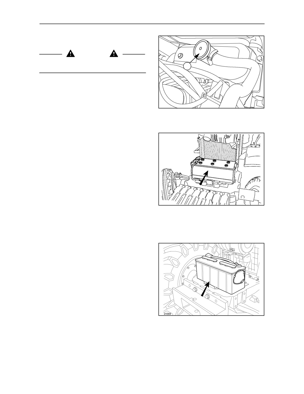
OPERATION 10
BATTERY CAPACITY 105 Ah. -- Fig. 14
NOTE: The 105 Ah capacity battery is located within
the front axle support.
To access the battery, lift the bonnet as described on
page 4--4 of this section.
TRE0035A
14
BATTERY CAPACITY 120 Ah -- Fig. 15
NOTE: The 120 Ah capacity battery is located on top
of the front axle support.
To access the battery, lift the bonnet as described on
page 4--4 of this section.
The electrolyte level must be checked with the
engine shut off, the tractor on a level surface and the
battery cold.
If the battery needs to be topped up frequently or
tends to run down, have the electrical system
checked by your dealer.
15
4--11
SECTION 4 -- LUBRICATION AND MAINTENANCE
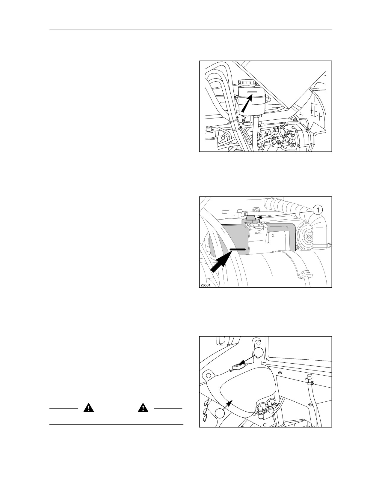
OPERATION 11
HYDROSTATIC STEERING RESERVOIR -- Fig. 16
Check the oil level and top up as necessary.
23754
16
OPERATION 12
RADIATOR EXPANSION TANK -- Fig. 17
The level must always be above the “MIN” mark
shown in the figure.
If necessary top up through the fill point (1).
MIN
17
OPERATION 13
WINDSCREEN WASHER BOTTLE -- Fig. 18
2
To add liquid to the windscreen washer bottle:
5. Remove the filler cap (1);
6. Add washer fluid to fill the bottle (2);
7. Replace the cap.
WARNING
1
In winter use water mixed with an antifreeze product.
TRE0833A
18
4--12
SECTION 4 -- LUBRICATION AND MAINTENANCE
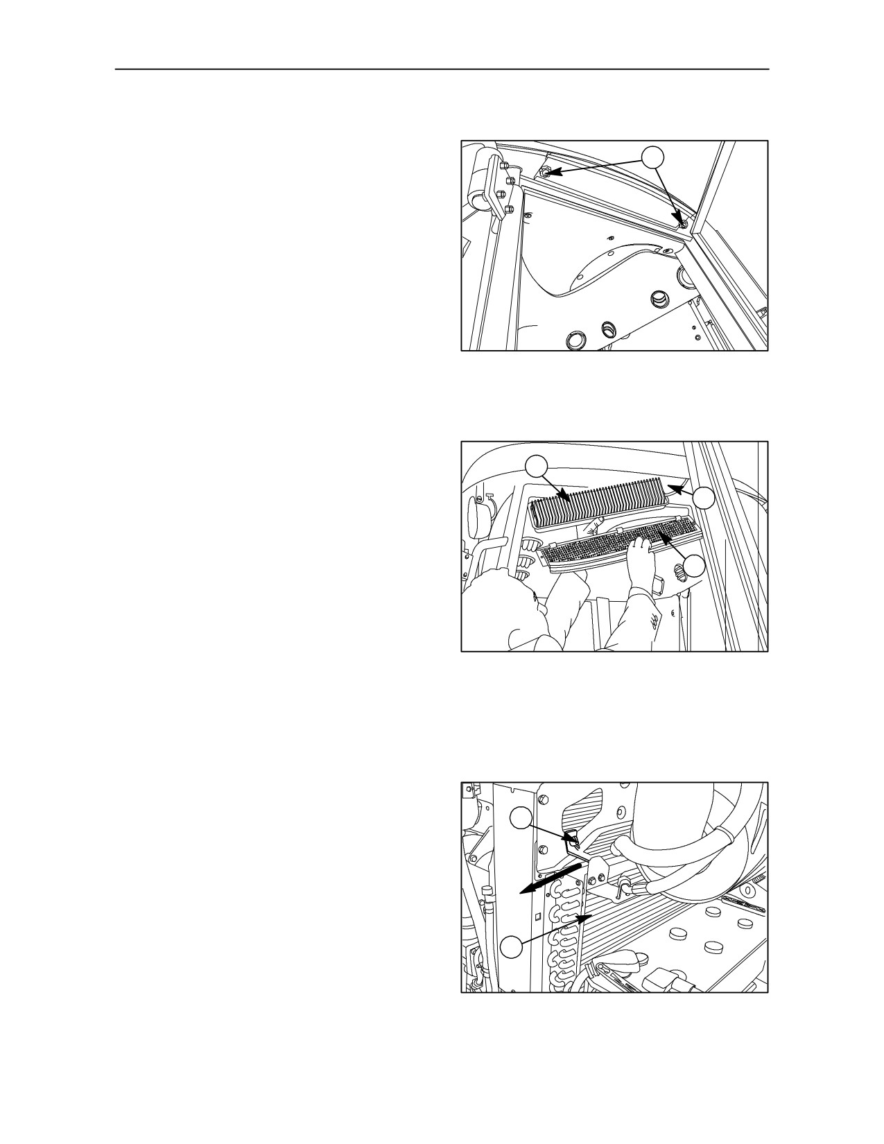
OPERATION 14
CAB AIR FILTER -- Fig. 19 -- 20
1
Unscrew the cover (4) retaining knobs (1), extract the
element (2) and clean:
--
by tapping gently on a flat surface with the
outward--facing part downwards;
or
--
with a jet of compressed air at less than 6.9 bar
(7 kg/cm2) (100 Psi);
TRE0834A
19
or
--
by immersing the filters in a solution of water and
non--foaming detergent for 15 minutes;
or
2
--
rinsing with a jet of water at less than 2.7 bar
(2.8
kg/cm2)
(39
Psi) and drying with dry,
3
non--compressed air.
Do not re--install the elements until they are
thoroughly dry. A damp air filter will rupture when the
4
heater/air conditioner is operated.
Clean filter seats (3) with a cloth. When refitting the
elements, the arrow on the label must face the inside
TRE0835A
of the cab.
20
OPERATION 15
AIR CONDITIONER CONDENSER --
Fig. 21-- 22
1
Slacken the retaining screw (1) on the condenser (2).
Slide the condenser sideways, in the direction of the
arrow and clean off any dirt accumulated between
the cooling fins. Check that they are not deformed
and, if necessary, restore them to proper working
condition.
2
TRE0836A
21
4--13
SECTION 4 -- LUBRICATION AND MAINTENANCE
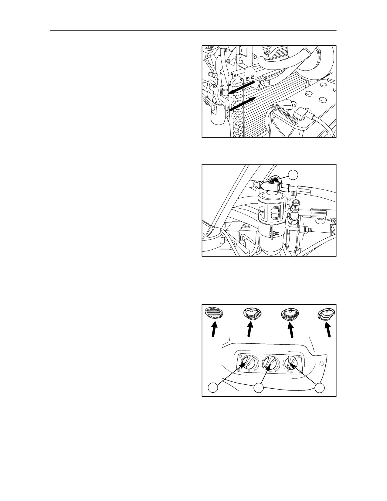
Slide the condenser back to its working position and
tighten the retaining screw (1).
TRE0837A
22
OPERATION 16
CAB AIR CONDITIONING SYSTEM --
Figs. 23 and 24
1
At the start of a period of use, check that the filter is
working properly as follows:
--
Turn the knob (3) fig. 24 clockwise to switch on
the air--conditioning;
--
Turn the temperature control knob (2) fig. 24 fully
anti--clockwise;
TRETRE0012A
--
Turn the electric fan control (1) fig. 24 to the
23
low--speed, first setting;
--
Place a thermometer next to the vents (arrowed
in the fig. 24) and check that the temperature
measured is around 15o C less than the external
temperature.
or
--
Check, with the air--conditioning on, that
inspection glass (1) fig. 23, on top of the filter, is
transparent; if white liquid or air bubbles can be
seen, the filter needs to be replaced.
NOTE: The filter must always be replaced when
work is carried out on the air--conditioning system.
Also, take this opportunity to check the oil level in the
compressor.
2
3
1
TRE0012A
24
4--14
SECTION 4 -- LUBRICATION AND MAINTENANCE
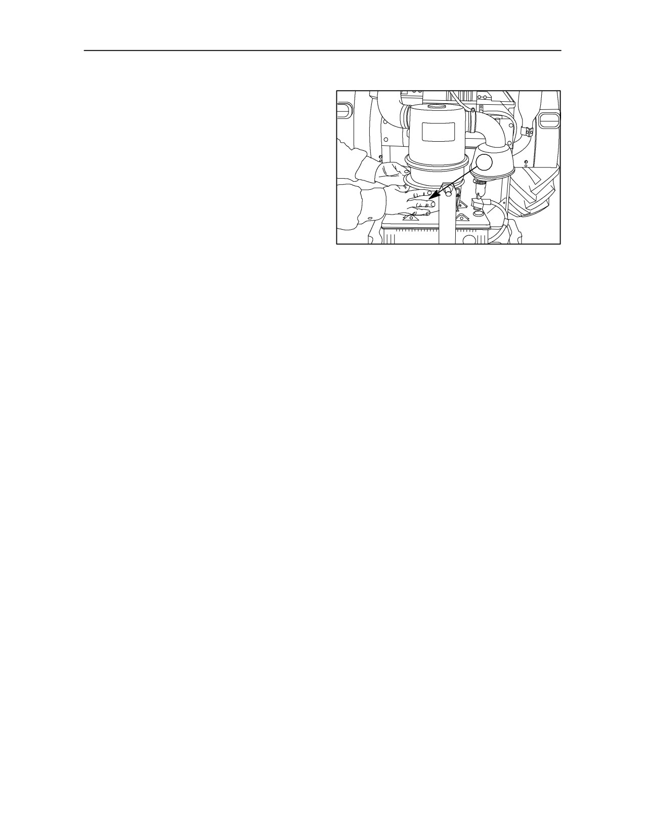
OPERATION 17 (NOT AVAILABLE FOR ALL
MARKETS & ALL MODELS)
OIL BATH AIR CLEANER -- Fig. 25
After the engine has been stopped for at least 15
minutes, remove the bowl (1) from the oil bath air
1
cleaner and check the oil level inside. The oil level
should be up to or slightly above the level line
stamped into the reservoir bowl.
If there is an accumulation of dirt in the filter bowl
approaching 1 cm or more, clean the bowl and refill
with fresh oil. Also clean inside the air cleaner casing
during every cleaning operation.
25
NOTE: Be aware that dirt in the oil will raise the oil
level in the air cleaner bowl.
4--15
SECTION 4 -- LUBRICATION AND MAINTENANCE
EVERY 50 HOURS
OPERATION 18
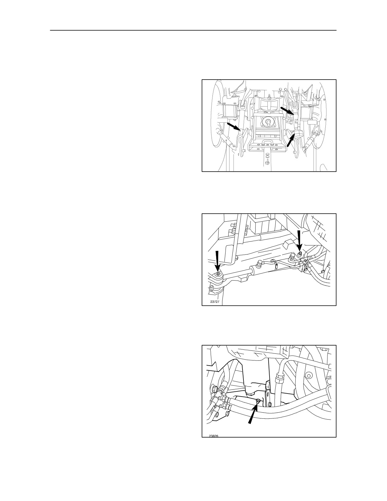
HYDRAULIC LIFT AND LINKAGE -- Fig. 26
Using a grease gun, pump AMBRA GR9 grease into
the three grease points shown.
TRE0839A
26
OPERATION 19
STEERING CYLINDERS 4WD -- Fig. 27
Using a grease gun, pump AMBRA GR9 grease into
the two lubrication fittings shown.
27
OPERATION 20
FRONT AXLE REAR PIVOT 4WD -- Fig. 28
Using a grease gun, pump AMBRA GR9 grease into
the lubrication fitting shown.
28
4--16
SECTION 4 -- LUBRICATION AND MAINTENANCE
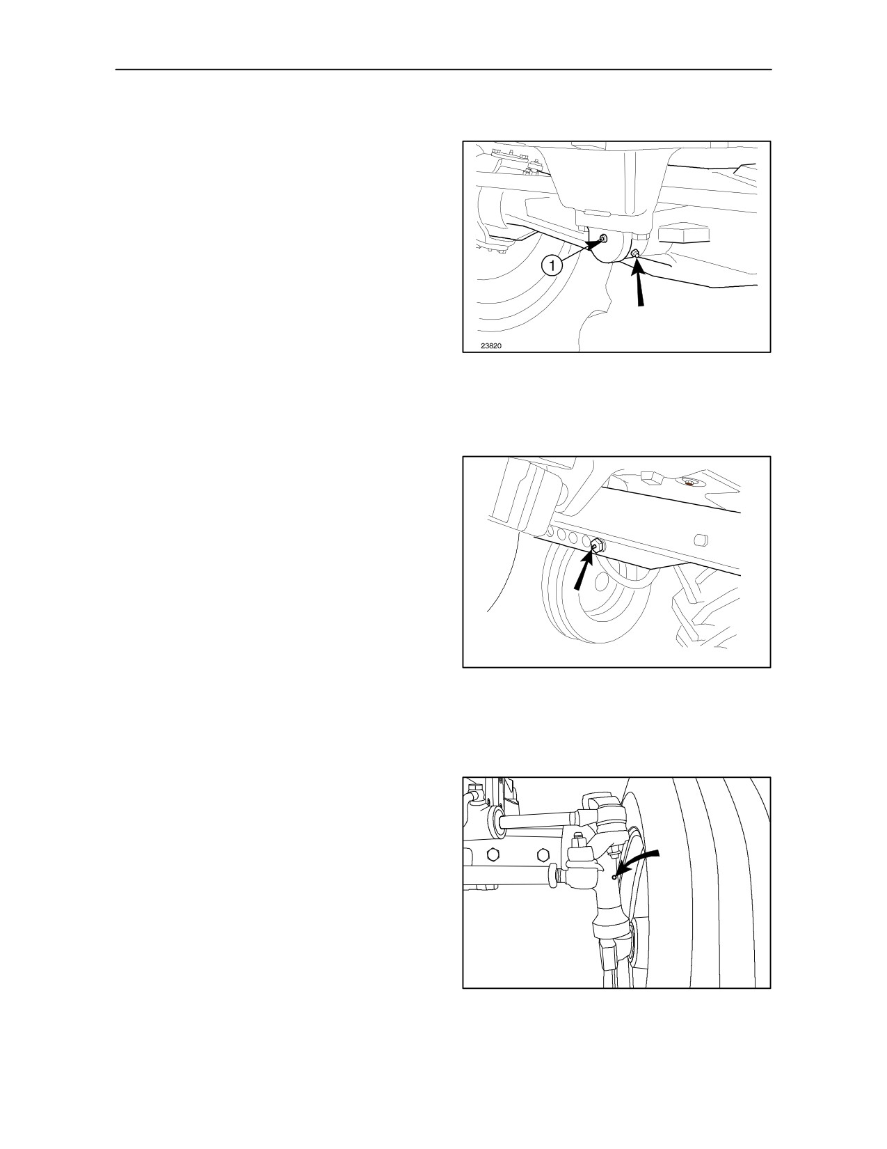
OPERATION 21
FRONT AXLE FRONT PIVOT 4WD -- Fig. 29
Using a grease gun, pump AMBRA GR9 grease into
the lubrication fitting (arrowed) until grease escapes
through outlet (1).
29
OPERATION 22
STEERING CYLINDER 2WD -- Fig. 30
and 31
Using a grease gun, pump AMBRA GR9 grease into
the lubrication fitting shown.
23823
30
OPERATION 23
RIGHT--HAND STUB AXLE 2WD -- Fig. 31
Using a grease gun, pump AMBRA GR9 grease into
the lubrication fittings shown.
TRE0840A
31
4--17
SECTION 4 -- LUBRICATION AND MAINTENANCE
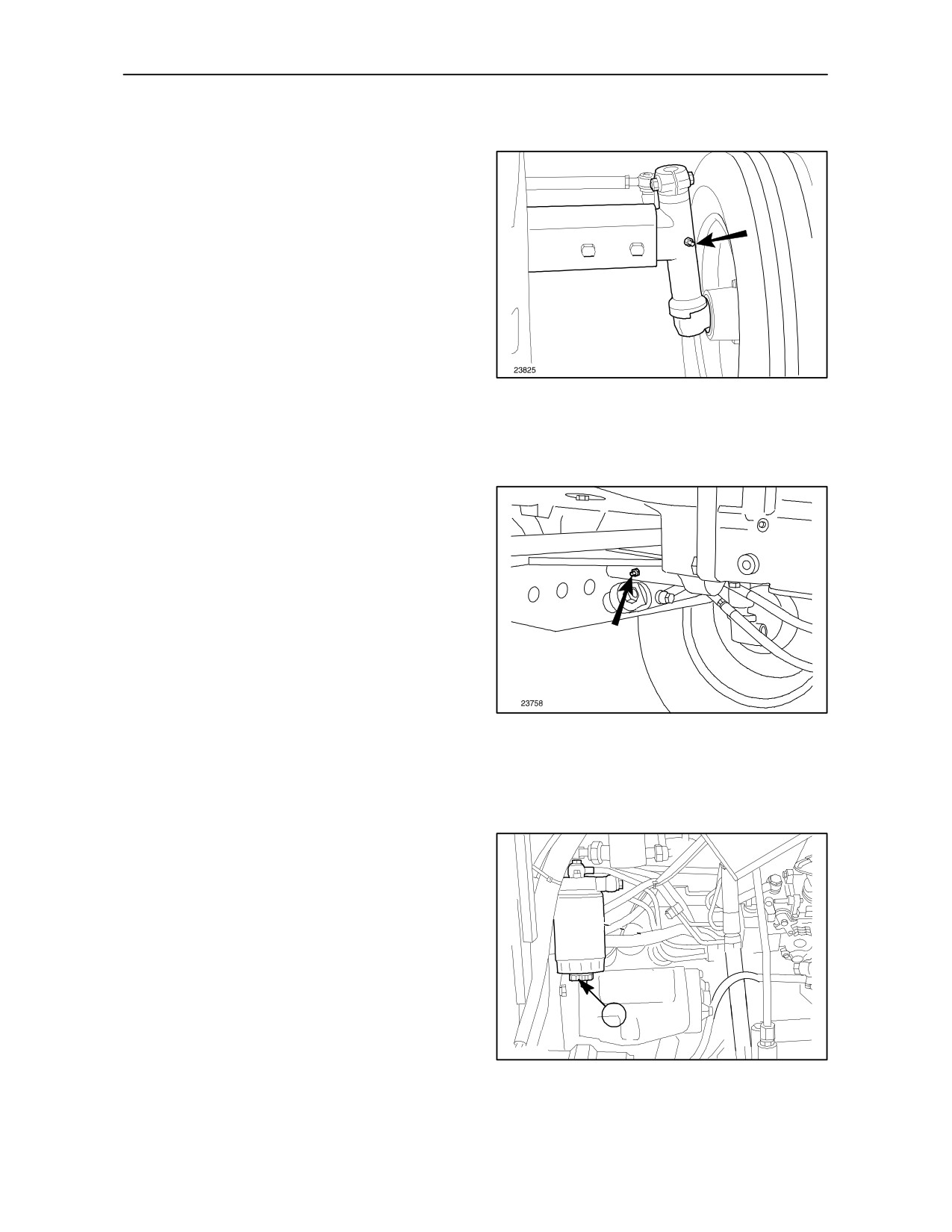
OPERATION 24
LEFT--HAND STUB AXLE 2WD -- Fig. 32
Using a grease gun, pump AMBRA GR9 grease into
the lubrication fitting shown.
32
OPERATION 25
FRONT AXLE PIVOT 2WD -- Fig. 33
Using a grease gun, pump AMBRA GR9 grease into
the lubrication fitting shown.
33
OPERATION 26
FUEL FILTER -- Fig. 34
Loosen the drain plug (1) approximately3/4 of a turn,
then operate the fuel pump primer lever to force
condensed water and sediment from the filter. When
only clean fuel drains from the filter, tighten the drain
plug.
1
23730A
34
4--18
SECTION 4 -- LUBRICATION AND MAINTENANCE
EVERY 300 HOURS OF WORK
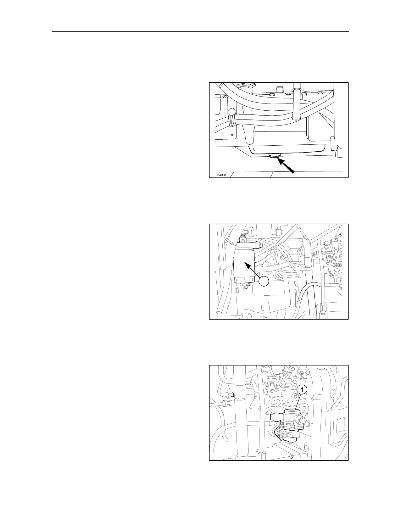
OPERATION 27
ENGINE OIL -- Fig. 35
Drain off all the oil via the sump plug shown and refill
with fresh oil using fill points (2) fig. 12 or (1) fig. 13
page 4--11.
35
OPERATION 28
FUEL FILTER -- Fig. 36
Unscrew and remove the filter cartridge (1). Install a
new filter cartridge.
Bleed air from the fuel system as described on page
4--31 in this section.
1
23730A
36
OPERATION 29
FUEL PUMP FILTER -- Fig. 37
Remove cover (1) and clean the internal filter screen.
23731A
37
4--19
SECTION 4 -- LUBRICATION AND MAINTENANCE
OPERATION 30
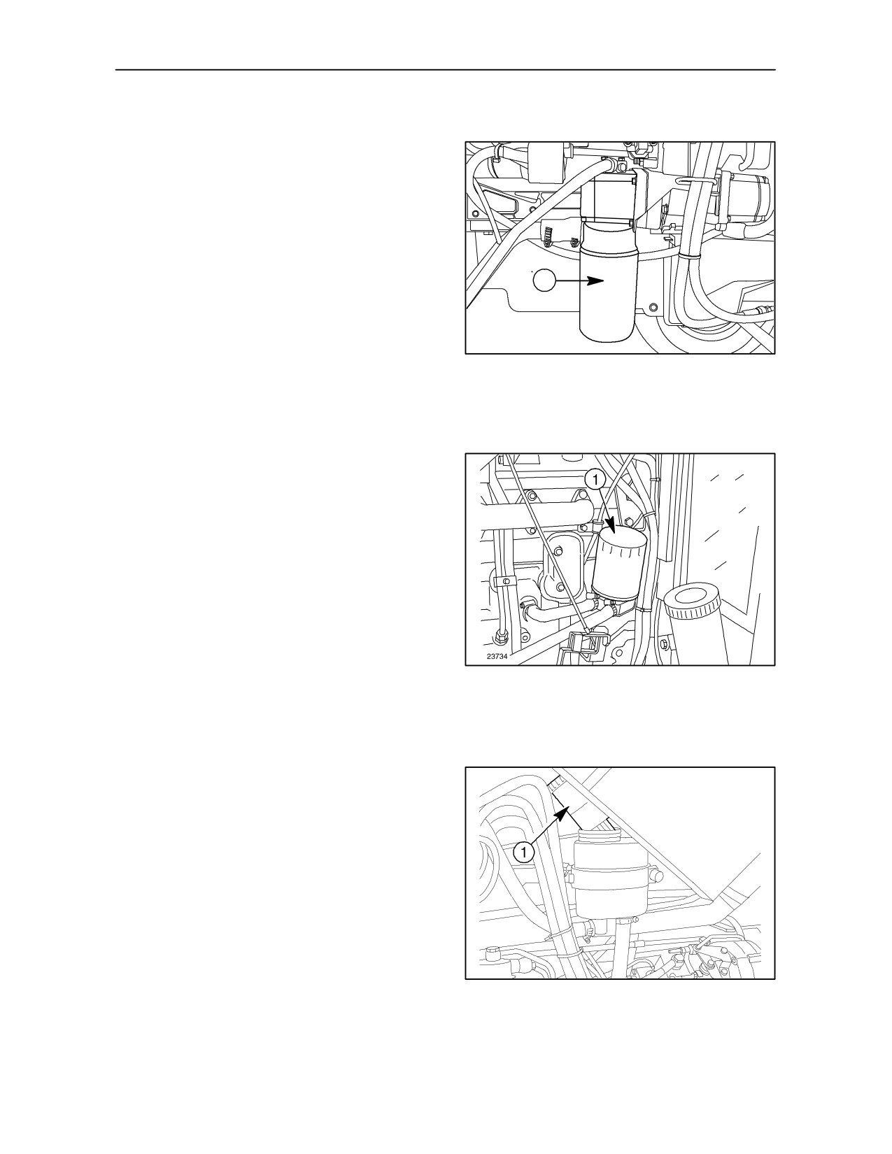
HYDRAULIC LIFT OIL FILTER -- Fig. 38
Unscrew and remove the filter (1). Oil the rubber seal
then screw on and tighten the cartridge3/4 of a turn
by hand. Top up the oil with fresh oil. (see operation.
no.35 page 4--21 ).
1
TRE0841A
38
OPERATION 31
ENGINE OIL FILTER -- Fig. 39
Unscrew and remove the filter (1). Oil the rubber seal
then screw on and tighten the cartridge3/4 of a turn
by hand. Top up the oil with fresh oil. (see operation
no. 9 fig. 12 and 13).
39
OPERATION 32
HYDROSTATIC STEERING -- Fig. 40
Remove the filter (1) (press downwards and move
sideways) and wash the filter, together with the filler
cap in mineral oil.
NOTE: For oil grades, see the lubrication charts
beginning on pages 4--41.
23759
40
4--20
SECTION 4 -- LUBRICATION AND MAINTENANCE
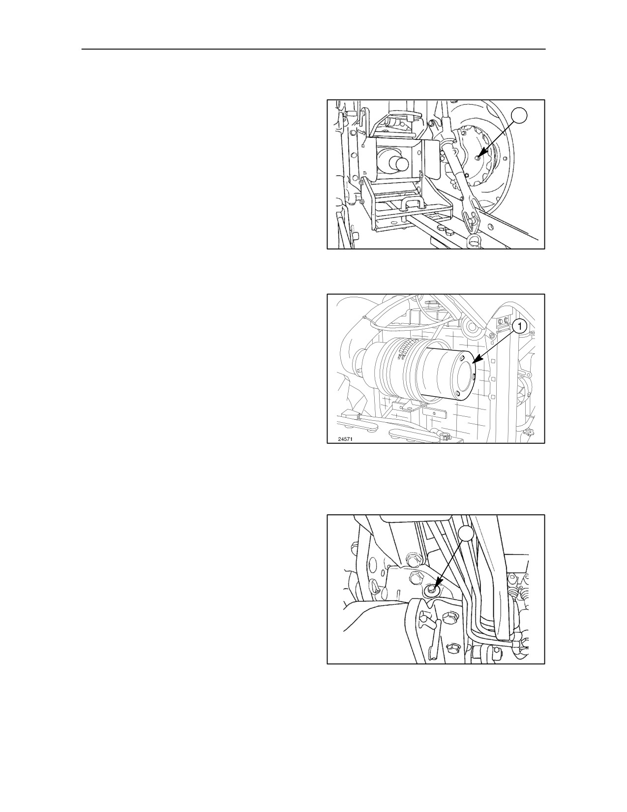
OPERATION 33
FINAL REDUCTION GEARS -- Fig. 41
1
Check the oil level as follows :
--
Park the tractor on a level surface.
--
Remove the plug (1). Some oil should flow out of
the plug hole. If necessary, top up via same plug
hole until the oil overflows.
TRE0016A
41
OPERATION 34
DRY AIR FILTER, EXTERNAL CARTRIDGE
-- Fig.
42
Remove the cover, take out external cartridge (1)
and clean as described in operation 9, on page 4--9
of this section.
42
OPERATION 35
TRANSMISSION AND HYDRAULIC LIFT --
Fig. 43
1
With the tractor on a level surface, the engine shut
off and the hydraulic lift linkage fully lowered, check
that the oil level reaches the ”MAX” mark on the
combined filler plug / dipstick (1).
If necessary, add oil through the fill point and replace
the plug.
NOTE: For oil grades, see the lubrication charts
TRE0015A
beginning on pages 4--41.
43
4--21
SECTION 4 -- LUBRICATION AND MAINTENANCE
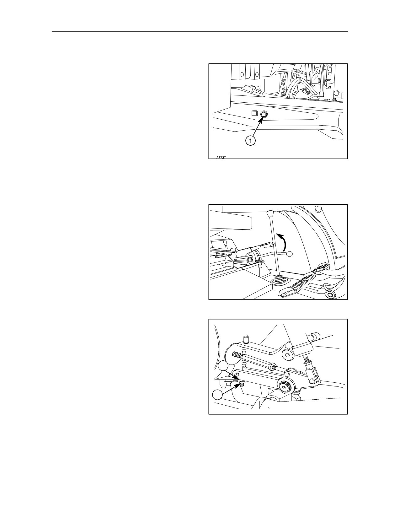
OPERATION 36
FRONT AXLE HOUSING 4WD -- Fig. 44
Check the oil level as follows:
--
Park the tractor on a level surface;
--
Remove the plug (1). Some oil should flow out of
the plug hole.
If necessary, top up via plug hole (1) until the oil
overflows.
NOTE: For oil grades, see the lubrication charts
44
beginning on pages 4--41.
OPERATION 37
HANDBRAKE -- Fig. 45 -- 46
The handbrake lever must be adjusted whenever
work is carried out on the unit or when the lever does
not engage with the third notch of the sector gear
when the handbrake is applied.
45
For all models (2WD and 4WD) (Fig. 46) proceed as
follows:
--
Slacken the lock nut (1)
--
Tighten or slacken the adjusting screw (2) until
the lever is engaged with the third notch, when
2
the handbrake is applied.
--
Tighten the lock nut (1).
1
46
4--22
SECTION 4 -- LUBRICATION AND MAINTENANCE
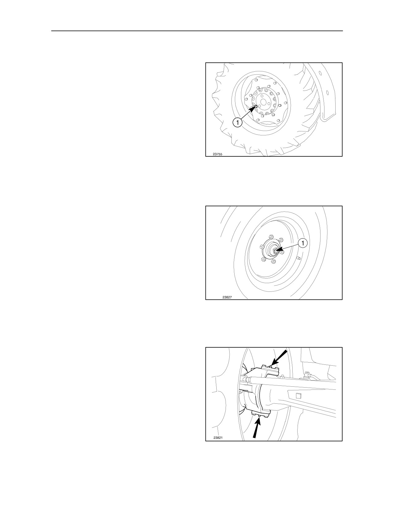
OPERATION 38
FRONT AXLE REDUCTION HUBS 4WD
-- Fig. 47
Check the oil level by rotating the wheel until the plug
(1) is at the horizontal position. If oil does not overflow
when the plug is removed, top up through the
opening and replace the plug.
NOTE: For oil grades, see the lubrication charts
beginning on pages 4--41.
47
OPERATION 39
FRONT WHEELS 2WD -- Fig. 48
Remove covers (1) from both hubs. Fill them with
AMBRA GR9 grease and replace.
48
OPERATION 40
FRONT AXLE SWIVEL BEARINGS 4WD
-- Fig. 49
At least twice a year, pump AMBRA GR9 grease into
the two lubrication fittings shown (two on each side).
49
4--23
SECTION 4 -- LUBRICATION AND MAINTENANCE
OPERATION 41
(NOT AVAILABLE FOR ALL MARKETS &
ALL MODELS)
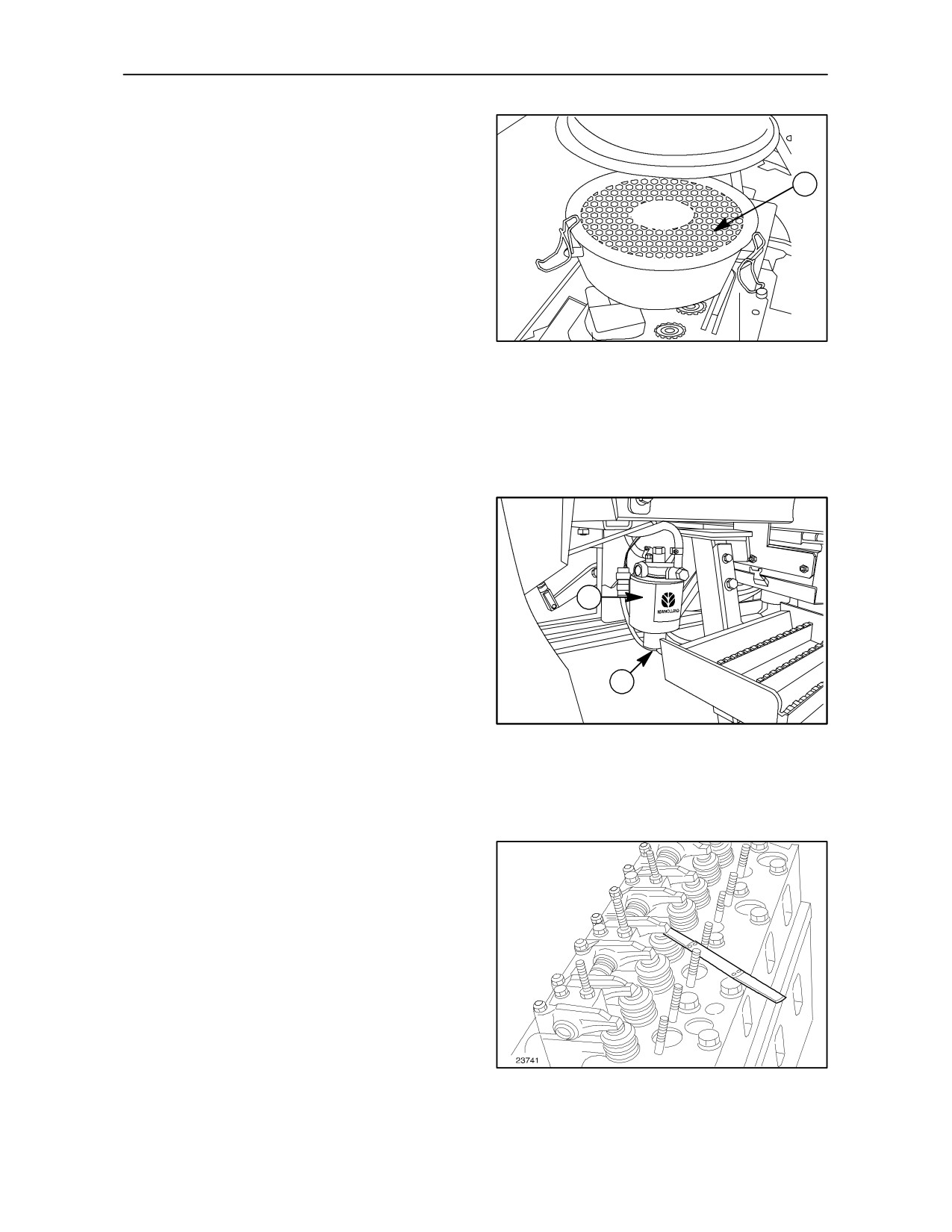
1
OIL BATH AIR CLEANER -- Fig. 50
Remove the filter parts and wash them with kerosene
(paraffin). After cleaning and drying, refill with fresh
engine oil up to the level line stamped into the side
of the bowl. Re--install the bowl assembly.
50
EVERY 600 HOURS OF WORK
OPERATION 42
FUEL SEDIMENTER-- Fig. 51
Unscrew the drain plug
(1) fig.
51. Turn the
sedimenter element
(2) completely to remove.
Replace the fuel sedimenter with new one. Install the
drain plug and tighten it carefully .
2
1
TRE0831A
51
EVERY 900 HOURS OF WORK
OPERATION 43
ENGINE VALVES -- Fig. 52
Contact your dealer to check the clearance between
the
valves
and
the
rocker
arms
(0.35 ± 0.05 mm; 0.012 ± 0.002 inches).
The inspection must be carried out when the engine
is cold.
52
4--24
SECTION 4 -- LUBRICATION AND MAINTENANCE
EVERY 1200 HOURS OF WORK
OPERATION 44
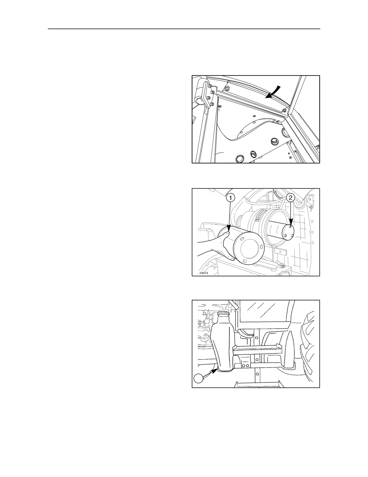
CAB AIR FILTER -- Fig. 53
Remove the grill shown, on left side, and replace the
filter element.
TRE0834A
53
OPERATION 45
DRY AIR FILTER -- Fig. 54
Remove the outer element (1), together with the
inner safety element (2).
Clean the inside of the casing with a damp, lint--free
cloth and install two new filters.
54
OPERATION 46
FUEL TANK -- Fig. 55
With the tractor on a level surface and the engine off,
drain the fuel as described below:
--
Place a container under the tank;
--
Remove plug (1) and drain the fuel to remove any
impurities in the tank.
Refill the tank with clean fuel and bleed the system
1
as described on page 4--31 in this section.
TRE0049A
55
4--25
SECTION 4 -- LUBRICATION AND MAINTENANCE
OPERATION 47
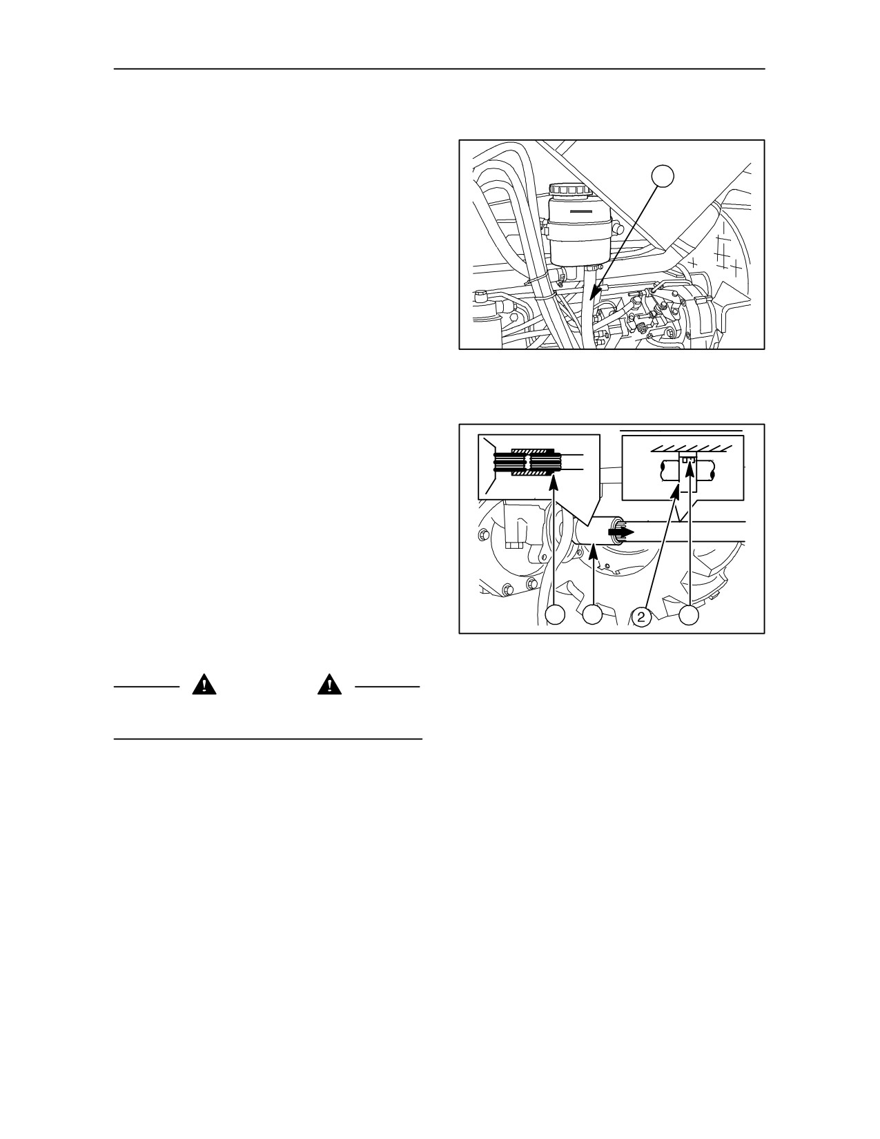
DRAINING THE HYDROSTATIC STEERING
OIL -- Fig. 56
1
Place a container under the reservoir, remove tube
(1) and drain the oil.
Refit the tube and clean the internal filter before filling
with new oil.
NOTE: For oil grades, see the lubrication charts
beginning on pages 4--41.
23762
56
OPERATION 48
DRIVE SHAFT SLEEVE FOR 4WD FRONT
AXLE CONNECTION -- Fig. 57
Check as follows:
--
Disassemble the front axle drive shaft guard;
--
Loosen screws (1), to disconnect the support (2)
from the drive housing;
--
Remove circlip (4);
--
Move the sleeve (3) as shown by the arrow, lower
4
3
1
the drive shaft until the sleeve can be removed
26245
and check that the inner groove does not show
57
signs of excessive wear.
WARNING
If the sleeve inner groove should prove excessively
worn, refer to your dealer for a possible replacement.
4--26
SECTION 4 -- LUBRICATION AND MAINTENANCE
EVERY 1200 HOURS OR EVERY
2
YEARS
OPERATION 49
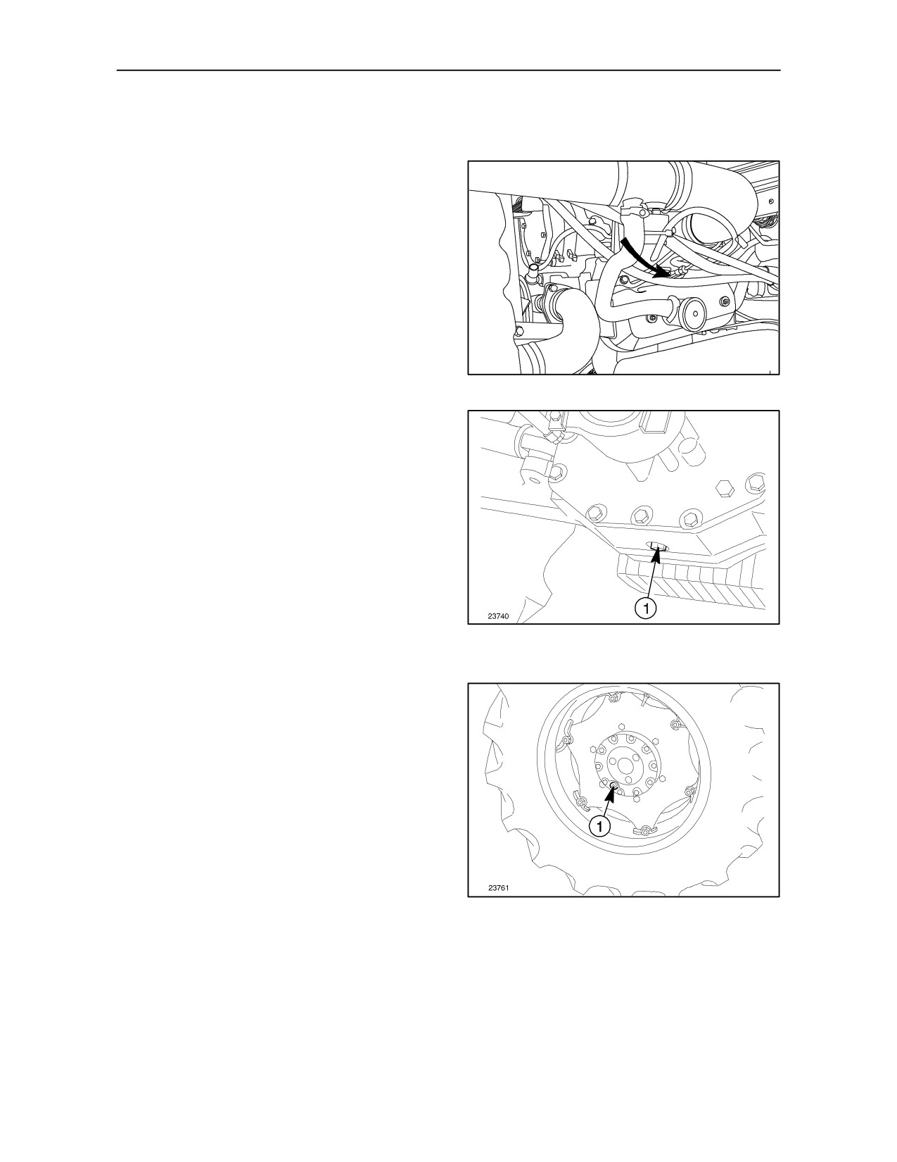
INJECTORS -- Fig. 58
Have your dealer check the pressure settings (see
page 8--6). To remove the injectors from the engine,
detach the lines and remove the connectors.
NOTE: Before loosening or disconnecting any part
of the injection system, thoroughly clean the area in
which you are going to work.
NOTE: Cover all injector lines and apertures to
prevent any dirt ingress.
TRE0844A
58
OPERATION 50
FRONT AXLE HOUSING -- 4WD -- Fig. 59
Place a container under the axle housing, unscrew
plug (1), let all the oil drain out. Refill with new oil
through the filler/level plug hole (1) fig
44.
NOTE: For oil grades, see the lubrication charts
beginning on pages 4--41.
59
OPERATION 51
DRAINING THE OIL FROM THE FRONT
AXLE FINAL DRIVES -- 4WD -- Fig. 60
Position plug (1) to its lowest point, place a container
under the plug hole and drain the oil.
Rotate the wheel so that the plug hole is in a
horizontal position and fill with new oil.
NOTE: For oil grades, see the lubrication charts
beginning on pages 4--41.
60
4--27
SECTION 4 -- LUBRICATION AND MAINTENANCE
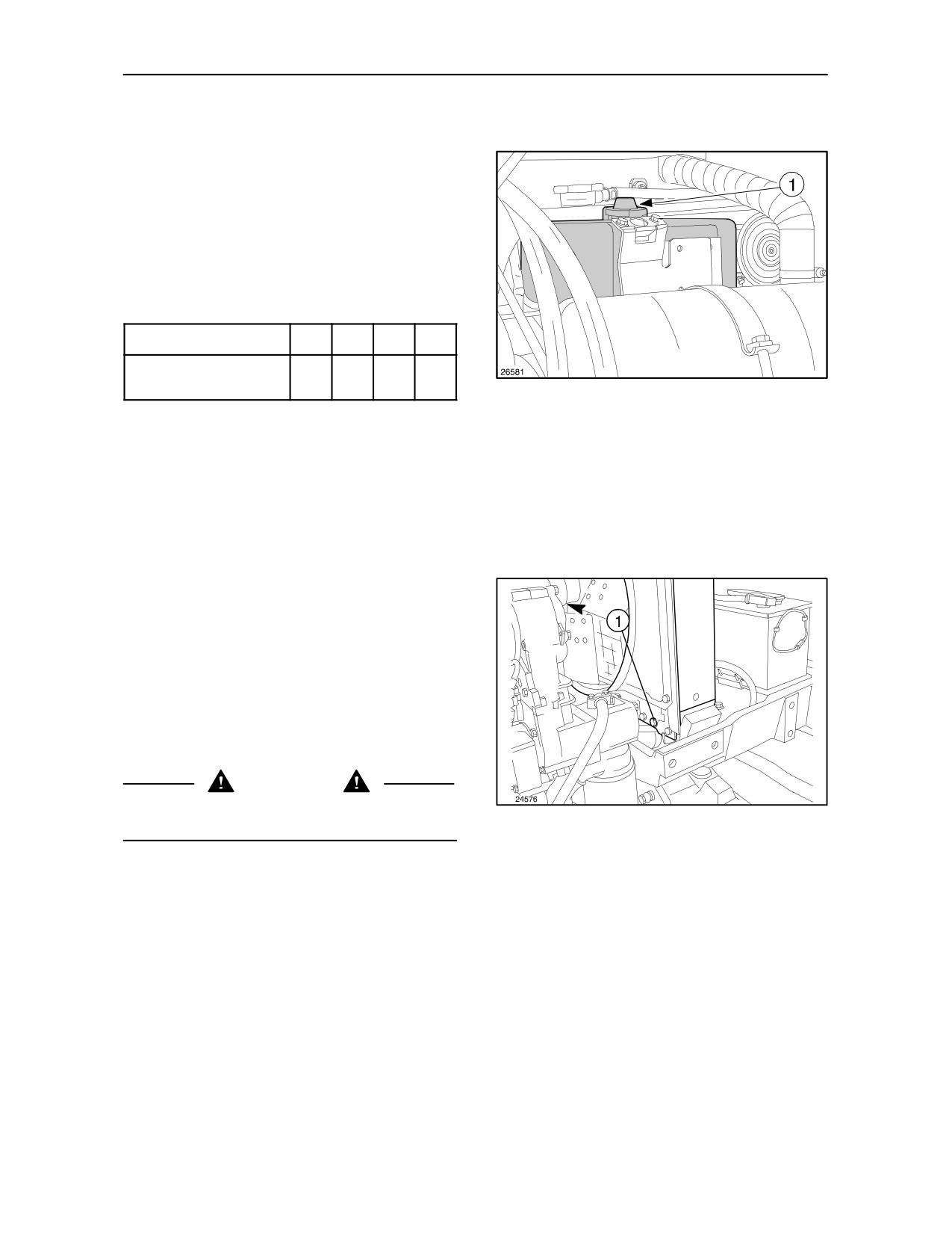
OPERATION 52
ENGINE COOLING SYSTEM
-- Figs.
61, 62 and 63
The system uses a mixture of AMBRA AGRIFLU
and water. This liquid has anti--oxidant,
anti--corrosive, anti--foaming and anti--crusting
properties. It is also non--freezing down to
temperatures of:
Degrees (°C)
--8
--15
--25
--30
% in volume of
20
30
40
50
AMBRA AGRIFLU to water
61
Your tractor is supplied with the cooling system filled
with an Ambra Agriflu solution appropriate to your
climatic conditions. This will guarantee the system
down to the temperature shown on the plate attached
to the bonnet.
This mixture will protect the cooling system for a
period of 2 years provided that during this time the
tractor has not been used for more than 1200 hours
in total. Flush the system and replace the anti--freeze
mixture when either of these limits have been
reached.
In emergencies, to prevent overheating, fill the
system by pouring water into the radiator opening (1)
fig. 63.
WARNING
Repair any damage and top up the mixture as soon
62
as possible, referring to the table above.
4--28
SECTION 4 -- LUBRICATION AND MAINTENANCE
FLUSHING THE SYSTEM (MODELS
WITHOUT CABS)
Flush at least every 1200 service hours or every
2 years, and whenever changing the anti--freeze in
the system.
Proceed as follows:
--
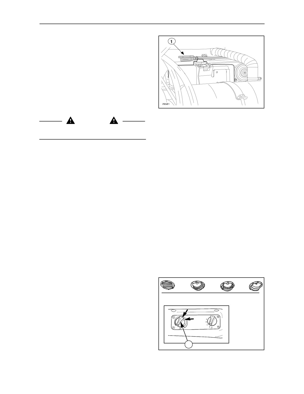
Remove the expansion tank cap (1) fig. 61.
Remove the radiator plug (1) fig. 62 and drain the
water while the engine is hot;
63
CAUTION
FLUSHING THE HEATING SYSTEM
The engine must be switched off when draining the
(MODELS WITH CAB)
water.
The heating system uses fluid from the engine
cooling system drawn off between the engine and the
--
Once the engine has cooled, fill the radiator with
radiator.
a filtered solution of Solvay soda and water at a
ratio of 250 grams (8.8 oz.) of soda to 10 litres
Flush the cooling system as described for models
(2.20 Imp gal. -- 2.70 US gal.) of water;
without cab, bearing in mind that the heating system
can be completely drained by turning temperature
adjustment control (1) fig. 64 to the vertical position
--
Run the tractor for approximately one hour and
A.
then drain the flushing solution;
Fill the engine cooling system and cab heating
--
Wait for the engine to cool down, then circulate
system as follows:
pure water by pouring it into the radiator and
allowing it to drain from radiator drain plug (1)
--
fill the radiator with a mixture of AMBRA AGRIFLU
fig. 62.
and water and fit the radiator filler cap;
--
Turn heating control (1) to red, (horizontal position
--
Replace the radiator plug, fill with water, run the
B), start the engine and run it for approx. 5 to 10
engine for a few minutes and drain the system;
minutes. (This operation is necessary to warm the
coolant in the engine cooling system);
--
Leave the engine to cool and top up to the normal
level.
--
Remove the upper radiator cap, turn the heating
control (1) to a vertical position and run the engine
THERMOSTAT
at maximum power for around five minutes;
There is a thermostat in the cooling circuit to prevent
--
Fill the radiator with the engine running at high
the water circulating in the radiator until the water
speeds until it is completely full, and fit the cap.
reaches a high enough temperature to allow the engine
to operate correctly (approximately 85_C).
If you think the thermostat may not be working
properly, remove it and have it checked by your
TRE0011B
dealer.
A
B
TRE0024A
1
64
4--29
SECTION 4 -- LUBRICATION AND MAINTENANCE
OPERATION 53
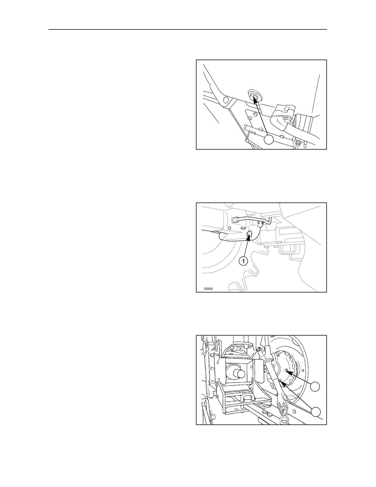
TRANSMISSION AND HYDRAULIC LIFT OIL
-- Figs. 65 and 66
Transmission housing
Place a container under the left side of the housing,
close to the fuel tank, and drain the oil via the plug
hole (1) fig. 65.
1
TRE0050A
65
Final drive, 4--wheel drive
Place a container under the final drive housing and
drain oil via plug hole (1) fig. 66.
Oil filters
Replace the hydraulic lift oil filter cartridge (operation
30) and hydrostatic steering and auxiliary systems
filter (operation 32).
When you have drained the oil, replace and tighten
the plugs and fill with new oil via fill point (1) operation
35.
NOTE: For oil grades, see the lubrication charts
beginning on pages 4--41.
66
OPERATION 54
FINAL REDUCTION OIL -- Fig. 67
Place a container under the final housing and drain
oil via hole (1) fig. 67.
When you have drained the oil, replace and tighten
the plugs and fill with new oil via fill point (2) fig. 41.
2
NOTE: For oil quantity, see the lubrication charts
beginning on pages 4--41.
1
TRE0016B
67
4--30
SECTION 4 -- LUBRICATION AND MAINTENANCE
GENERAL MAINTENANCE
BLEEDING THE FUEL SYSTEM
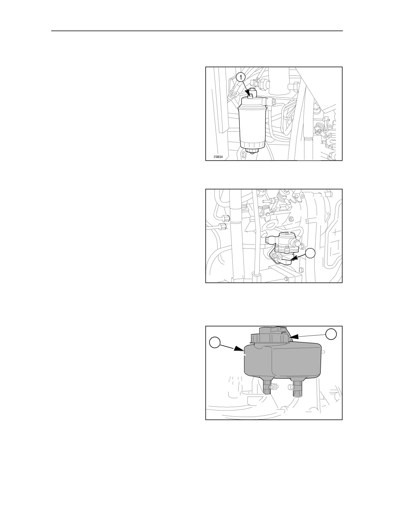
Bleeding procedure -- Figs. 68 and 69
During long periods when the tractor is not used,
when the filter and fuel lines are removed or when
there is no fuel in the tractor, air may enter the fuel
system.
The presence of air makes it difficult to start the
engine and it therefore needs to be bled as follows
when the fuel tank is refilled:
1. Unscrew the bleed plug
(1) fig. 68
by
approximately two turns.
68
2. Actuate lever (1) fig. 69 until fuel without air
bubbles spurts from the bleed hole.
3. Tighten plug (1) fig. 68.
4. After tightening the bleed plug (1) fig. 68, actuate
lever (1) fig 69 a few times.
5. Turn the ignition key to position C, as shown in
Section 2, fig.
18, page 2--11. As soon as the
engine starts, release the key.
1
NOTE: Your engine is fitted with a rotary injection
pump, whose internal components must be
protected from rusting if not used for over a month.
23731A
Therefore, before stopping the tractor, mix PROT 10
W/M oil with the fuel in the tank in a proportion of
69
10% and run the engine for approximately half an
hour.
BLEEDING THE HYDRAULIC BRAKE
SYSTEM
Bleeding procedure -- Figs. 70 to 73
2
1
Whenever work is carried out on the front brake hy-
draulic system, the air must be bled from the system.
Proceed as follows.
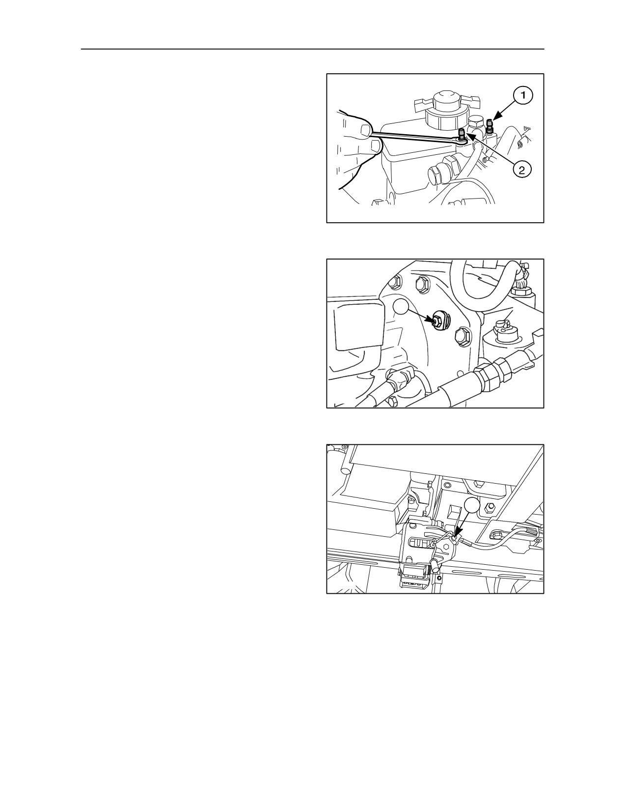
1. Thoroughly clean the external parts of the unit
around the hydraulic fluid tank cap (2) fig. 70 and
the bleed screws (1--2) fig.
71.
2. Make sure that the hydraulic fluid in the tank (1)
70 is maintained up to the full mark both before
and during the bleeding operations.
TRE0305A
NOTE: Filter all drained oil before reusing.
70
4--31
SECTION 4 -- LUBRICATION AND MAINTENANCE
3.
Depress the LH brake pedal, slowly and to the
end of its travel, so that the oil is placed under
pressure.
4.
Keeping the pedal depressed, undo the bleed
screw (1) fig. 71 by half a turn and allow the oil
mixed with air bubbles to flow out.
5.
Retighten the screw (1) fig. 71 and repeat the
above operations until the oil that comes out is
free of air bubbles.
TRE0307A
71
6.
Depress the LH brake pedal again to place the
circuit under pressure. This occurs when the
travel of the pedal returns to normal.
1
7.
Repeat the above operations for the RH brake
pedal by tightening or loosing bleed screw (2)
fig. 71.
8.
Depress the LH and RH brake pedal, slowly and
to the end of the travel, so that the fluid is placed
under pressure.
TRE0237A
72
9.
Keeping the pedals depressed, loosen the bleed
screw (1) fig. 72 and (3) fig. 73 (optional for TD
60 and TD 70 models ) by half a turn and allow
the fluid mixed with air bubbles to flow out.
3
10. Retighten the screw (1) fig.
72 and (3) fig. 73
(optional for TD 60 and TD 70 models ) and re-
peat the above operations until the fluid that
comes out is free of air bubbles.
11. When the operation has been completed, replen-
ish the fluid in the tank (1, fig.
70).
TRE0845A
73
4--32
SECTION 4 -- LUBRICATION AND MAINTENANCE
ELECTRICAL SYSTEM
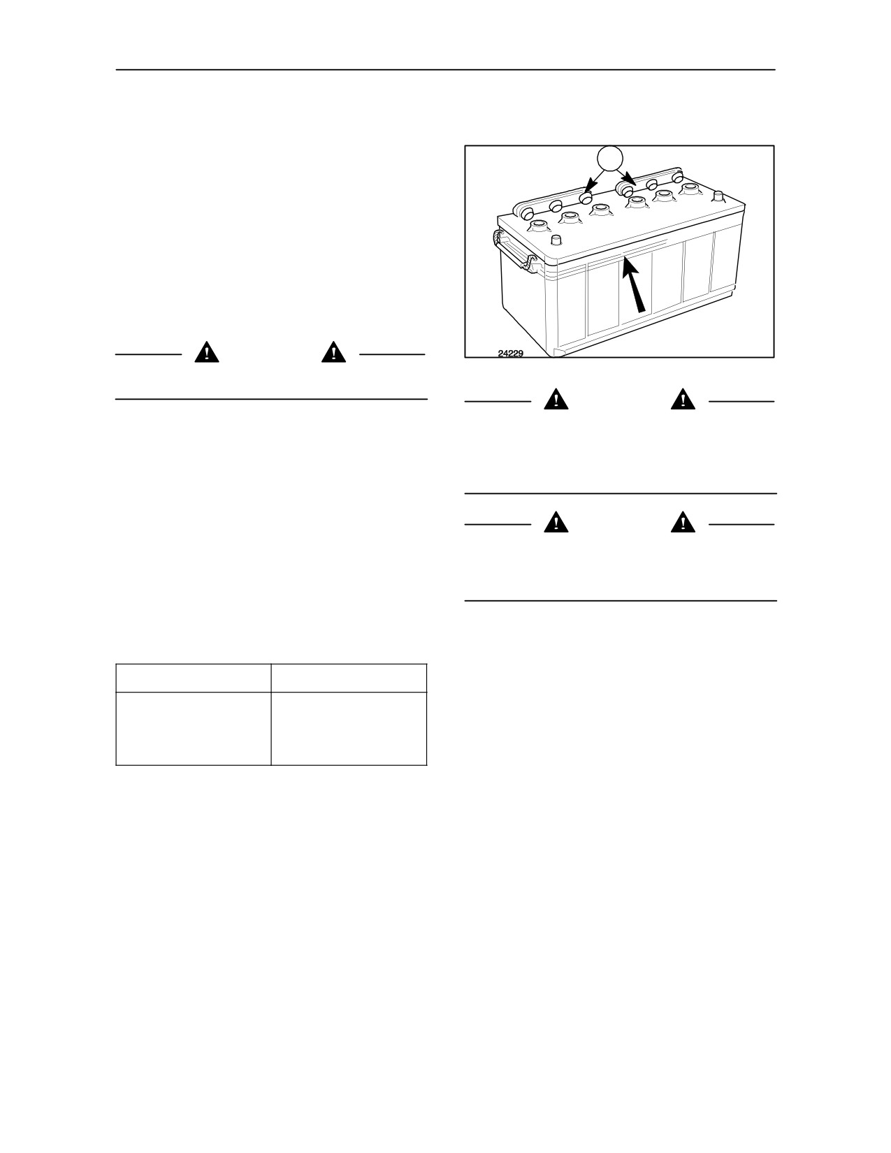
BATTERY -- Fig. 74
1
The tractors are fitted with maintenance--free
batteries.
Keep the top part clean and dry.
Check that the level of electrolyte reaches the top
mark and never falls below the lower mark.
If necessary lift covers (1) and add distilled water.
CAUTION
74
Never top up the battery with SULPHURIC ACID.
CAUTION
Never use rapid ”boost” battery chargers to recharge
Before recharging the battery, always disconnect the
the battery.
cables. The battery should be removed from its
location and recharged at a safe distance from the
tractor.
Check the charge with a digital voltmeter in the
following way:
DANGER
--
connect the voltmeter to the battery’s two
terminals, matching the terminal symbols
When recharging the battery, keep the premises well
(negative to negative and positive to positive)
ventilated and keep naked flames or cigarettes well
and read the value from the instrument;
away.
--
compare the figure with the values in the table
below to establish the charge in the battery.
NOTE: Batteries and storage batteries contain
components that may be damaging to the
environment if incorrectly disposed of after use. The
Voltage (V)
Charge level (%)
manufacturer strongly advises that all “dry” batteries,
used in electrical or electronic systems, are returned
12.66
100
to your authorised dealer. The dealer will dispose of
12.45
75
(or recycle) the batteries correctly. This procedure is
12.30
50
a legal requirement in certain countries.
12.00
25
NOTE: If it is necessary to replace the old battery
with a new one proceed as follows:
If the voltage is around 12.30 Vor lower, immediately
recharge the battery with a current equivalent to1/10
--
First disconnect the lead end marked with a
of the capacity in Ah a 50 Ah battery is to be charged
negative sign (--), then the lead end with the
at 5 Amp).
positive sign (+);
NOTE: If the battery frequently needs to be topped
--
Fit the new battery in the correct position. Do not
up or if it should tend to run down, have the electrical
over--tighten the retaining screws;
system of your tractor checked by your dealer.
--
Clean the lead ends and connect them to the
battery terminals, ensuring that the negative
terminal (--) is connected last;
--
Fully tighten the lead ends on the terminals and
smear them with petroleum jelly.
4--33
SECTION 4 -- LUBRICATION AND MAINTENANCE
ADVICE ON STARTING THE ENGINE WITH A
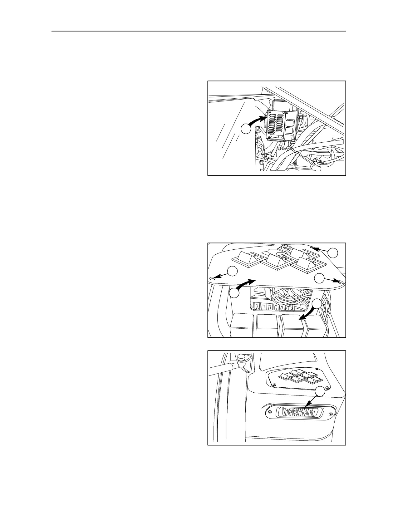
MAIN FUSE AND RELAY BOX--Fig. 75
FLAT BATTERY OR NO BATTERY
Onallmodels, thefusebox(1)islocatedontheright--
To prevent damage to the alternator and its
hand side of the engine compartment under the
incorporated voltage regulator follow the procedure
bonnet.
below:
When the tractor battery is partially discharged,
and an auxiliary battery has to be used to start the
engine, connect the auxiliary battery to the tractor
battery ensuring that the terminal symbols match
1
(positive to positive and negative to negative). Connect
the positive lead first followed by the negative lead.
Start the engine using the key start switch. When the
engine starts, allow it to run at idle speed, turn on all
electrical equipment
(lights, etc.). This will help
protect the alternator from possible damage due to
75
extreme load changes. Now disconnect the auxiliary
FUSES AND RELAYS (Inside cab)
battery leads. Remove the negative lead first,
Fig. 76-- 77
followed by the positive lead.
On tractors fitted with a cab, the fuses (1) and relays
If you have to start the engine with a totally flat
(4) are located inside the cab, beneath the
battery or where the tractor does not have a
right--hand console. To access the fuses and relays,
battery remember that:
remove the screws (2) and take off the cover (3).
--
it is not possible to start the tractor by towing as
the electro--magnetically operated injection pump
2
cut--off will prevent the engine from starting;
2
--
it is however necessary to connect a 12 V
2
auxiliary battery capable of starting the tractor
3
Under normal conditions, the engine must never be
run unless plug D+, terminal B+ and the condenser
4
are disconnected from the alternator.
When recharging the tractor battery, it must be
TRE0847A
removed from the tractor to avoid possible damage
to the alternator and related circuits. Observe the
76
rule relating to lead connection (positive to positive
and negative to negative).
1
77
4--34
SECTION 4 -- LUBRICATION AND MAINTENANCE
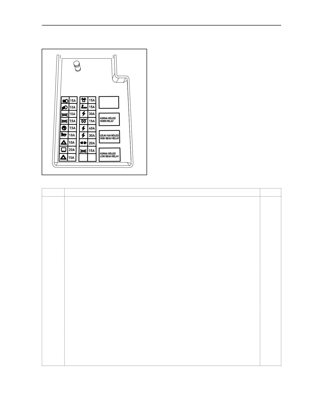
FUSES AND RELAYS MAIN BOX
78
Fuses
PROTECTED CIRCUITS
Amps
1
Main beam headlights
15
2
Dipped beam headlights
10
3
Front right and rear left side lights
10
4
Front left and rear right side lights
7,5
5
Engine shut--down solenoid
7.5
6
Instruments, turn signal switch, horn
10
7
Hazard warning switch, fuel sedimentor
10
8
Relays
20
9
Hazard warning switch
15
10
Beacon lamp, (radio, interior lamps-- with cab models)
15
11
Cigarette lighter
15
12
Power for cab (with cab models)
30
13
Thermostart
15
14
Power socket (with cab models)
40
15
Power for cab (with cab models)
30
16
Turn signal switch
20
17
Brake lights
15
I
Dipped beam relay
--
II
Main beam relay
--
III
Horn relay
--
IV
Brake relay
--
4--35
SECTION 4 -- LUBRICATION AND MAINTENANCE
FUSES AND RELAY BOX (INSIDE CAB)
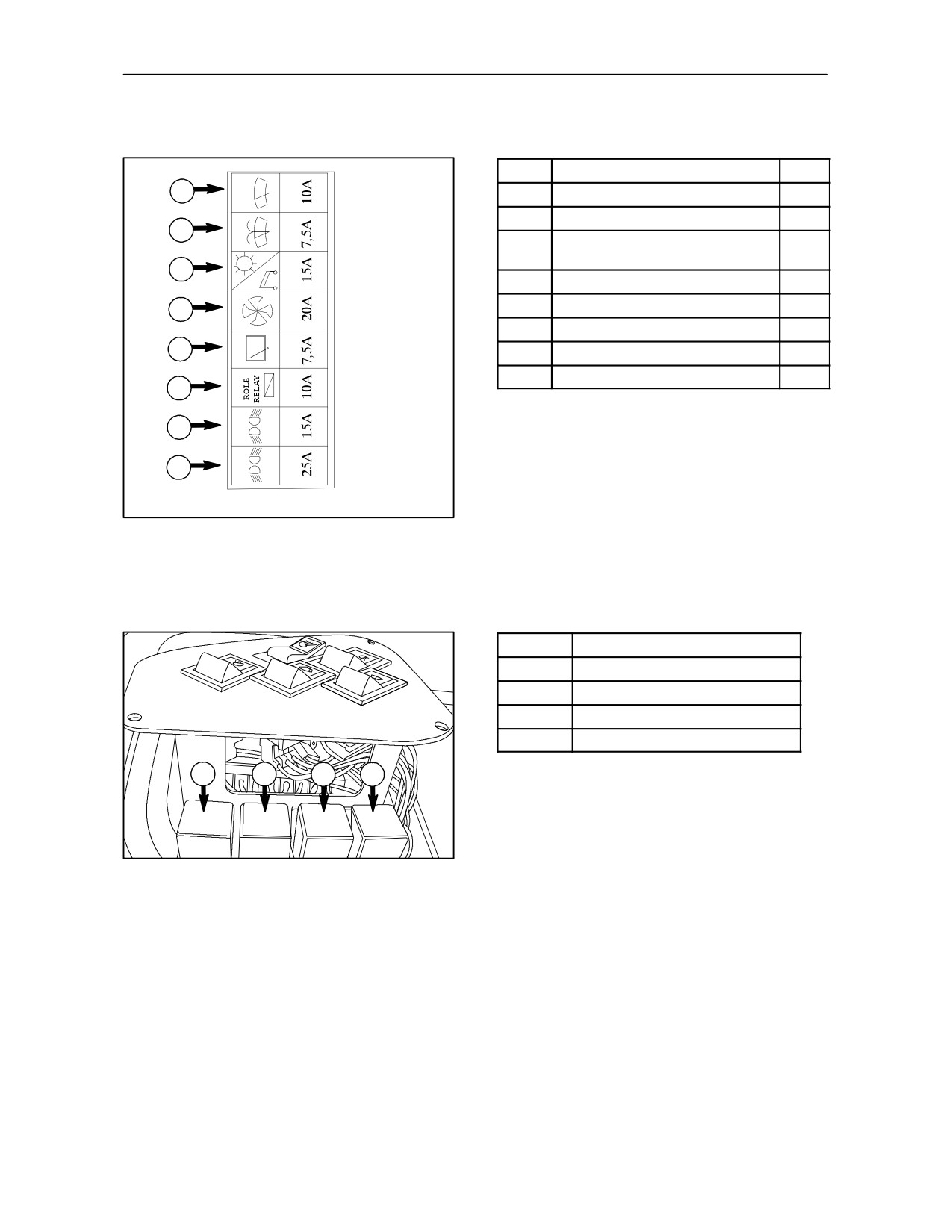
Fuses and protected circuits are listed below:
FIG-- 79 --
80
Fuses
PROTECTED CIRCUITS
Amps
1
1.
Front wiper
10
2.
Washer
7.5
2
Beacon lamp, interior lamps,
3.
15
radio
3
4.
Heater/Air Conditioning
20
5.
Rear wiper
7.5
4
6.
Working lamps switches
10
5
7.
Front working lamps
15
8.
Rear working lamps
25
6
7
8
79
Relays and related circuits are listed below:
Relays
CIRCUITS
1.
Front work lights
2.
Rear work lights
3.
Power supply
4.
Power supply
1
2
3
4
TRE0847A
80
4--36
SECTION 4 -- LUBRICATION AND MAINTENANCE
81
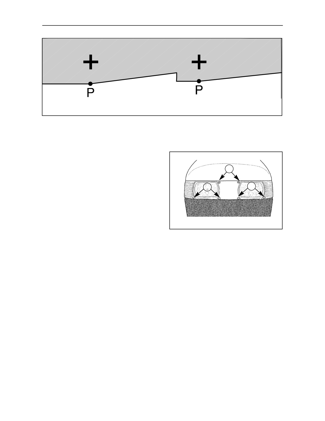
FRONT HEADLIGHT ADJUSTMENT
-- Figs. 81 and 82
1
Adjust the headlights as follows:
--
Unload the tractor and inflate the tyres to the
1
1
specified pressure on level ground in front of -- if
possible -- a shaded white wall.
--
Mark two crosses on the wall corresponding to
the middle of the headlamps.
TRE0051A
--
Reverse the tractor about 5 m. and switch on the
82
main beam headlights.
NOTE: Under the EC regulations, the maximum
--
Points P -- P should be 5 cm below the crosses.
permissible overall width for tractors equipped with
standard tail--lights is 2150 mm. With wheels set at
--
— To adjust the light beams, turn the screws (1)
maximum track width, the maximum overall width
to deflect the beams horizontally or vertically.
obtainable is 2315 mm for machines with ROPS, and
2510 mm for machines with cab. If these wider
Replace bulbs which have blown by bulbs of the
settings are adopted, the tail--lights must be mounted
same power (55/60 W).
to special extendible arms (available on request) so
that they can be adjusted to indicate the overall width
of the tractor.
4--37
SECTION 4 -- LUBRICATION AND MAINTENANCE
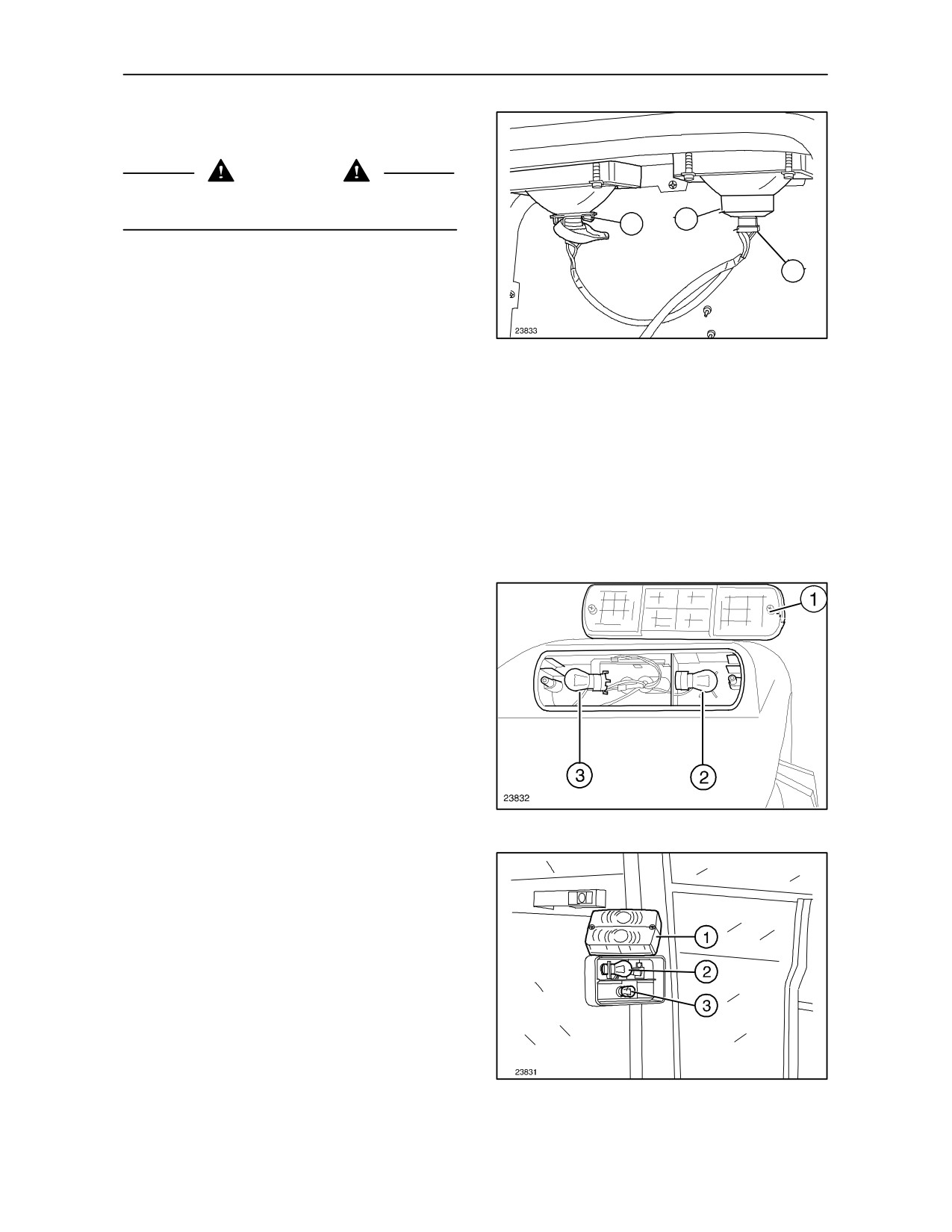
REPLACING THE FRONT HEADLIGHT
BULBS -- Fig. 83
WARNING
When handling halogen bulbs never touch the bulb.
Touch only the metal part.
2
3
If the bulb comes into contact with your fingers, it will
1
reduce the intensity of the light emitted and
adversely affect service life. In the event of contact,
clean the bulb with a cloth soaked in alcohol and
leave to dry.
83
Replace blown bulbs as follows:
1. Unscrew the connector (1);
2. Remove the rubber protector (2);
3. Unclip the retaining spring (3) and unscrew the
bulb anti--clockwise.
Replace the old bulb with another halogen one of the
same power (55/60 W).
REPLACING THE REAR SIDE, STOP AND
INDICATOR LIGHT BULBS -- Fig. 84
Remove the transparent cover
(1), press the
defective bulb in, twist a1/4 turn anti--clockwise and
remove it. Replace it with a bulb of the same power:
(2) Indicator light -- 21 W;
(3) Brake lights and side lights
-- double filament,
21 W / 5 W.
NOTE: The transparent amber cover must be fitted
84
over the outer edge of the mudguard.
REPLACING THE FRONT SIDE, STOP AND
INDICATOR LIGHT BULBS -- Fig. 85
Remove the transparent cover
(1), press the
defective bulb in, twist a1/4 turn anti--clockwise and
remove it. Replace it with a bulb of the same power:
(2) Indicator light -- 21W;
(3) Side lights -- 5W.
NOTE: The transparent cover must be fitted with the
amber section above the clear section.
85
4--38
SECTION 4 -- LUBRICATION AND MAINTENANCE
TRE0850A
86
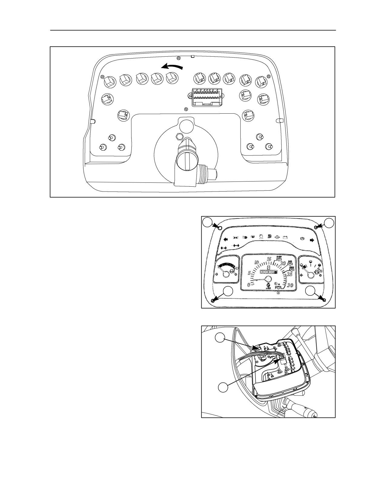
REPLACING THE WARNING LIGHTS IN THE
1
1
INSTRUMENT PANEL
Replace warning / indicator bulbs as follows:
--
Unscrew the four screws (1) fig. 87;
--
Remove the instrument panel from its seat and
disconnect terminal
(1) fig. 88
from the
tachometer;
1
1
--
Disconnect connector (2) fig. 88 and remove the
TRE0027B
instrument;
87
--
Unscrew the defective bulb, fig. 86, anti--
clockwise by1/4 of a turn, remove and replace
with a bulb of the same power.
1
--
Alternator charge indicator -- 3 W;
--
All other bulbs -- 2 W.
2
TRE0851A
88
4--39
SECTION 4 -- LUBRICATION AND MAINTENANCE
RECOMMENDATIONS FOR BODYWORK MAINTENANCE
Protection against atmospheric agents
BODYWORK AND CAB
Over the years, the Company has introduced a
Where there are abrasions or deep scratches, which
series of measures to protect the tractor from the
expose the underlying metal, they need to be
deterioration and corrosion which can be caused by
retouched immediately with genuine products as
various external elements, such as those listed
follows:
below:
--
rub down the area thoroughly;
--
salinity and humidity in the atmosphere;
--
apply the primer;
--
atmospheric pollution (industrial areas);
--
leave to dry and then rub down lightly;
--
abrasive action of solid substances;
--
apply the paint;
--
using tractor in the presence of aggressive
chemical and/or organic substances;
--
lastly, polish.
--
physical damage such as dents, abrasions or
The paint can normally be maintained by washing at
deep scratches.
intervals which vary depending on the conditions of
use and the environment. In areas prone to
The technical response to these problems was:
atmospheric pollution and in coastal areas, wash
more frequently, whereas if organic or chemical
--
highly corrosion--resistant zinc plating;
substances are present, wash immediately after the
tractor is used. Use a low--pressure water spray,
sponge down with a solution of 2 to 4% shampoo in
--
paint systems and paints which help the tractor
water, rinsing the sponge frequently, rinse the tractor
resist corrosion and abrasion;
thoroughly and dry it, if possible, with an air jet.
--
application of suitable hardened plastic-coatings
Avoid washing the tractor after it has been standing
to points which are particularly exposed to
in the sun and when the engine is still hot in order to
corrosion (edges, projections and sheet--metal
protect the shine on the paint.
welded joints);
It is good practice to protect the paint by polishing it
Unfortunately, external agents act in various ways
with specialised products (silicone waxes) from time
depending on environmental conditions and tractor
to time and, when the paint starts to dull, you can use
use; if the user takes enough care, however, his tractor
wax polish which has a slight abrasive action.
can be maintained in substantially better condition.
CAB MAINTENANCE
The following information is provided to help achieve
this aim.
After carrying out the external maintenance of the
cab, proceed as follows:
1. Periodically check that no water remains in areas
covered with mats or padding.
2. Protect the hinges and locks on the doors and
opening windows with lubricants and
water--repellents.
3. Use suitable detergents or, if necessary,
sulphuric ether to clean the windows.
4. Remove the windscreen wiper blade and
sprinkle the rubber with talc.
5. Leave the door or a window partially open.
4--40