New Holland TD 60D, TD 70D, TD 80D, TD 90D, TD 95D Tractor. OPERATOR’S MANUAL - page 3
SECTION 3 -- FIELD OPERATIONS
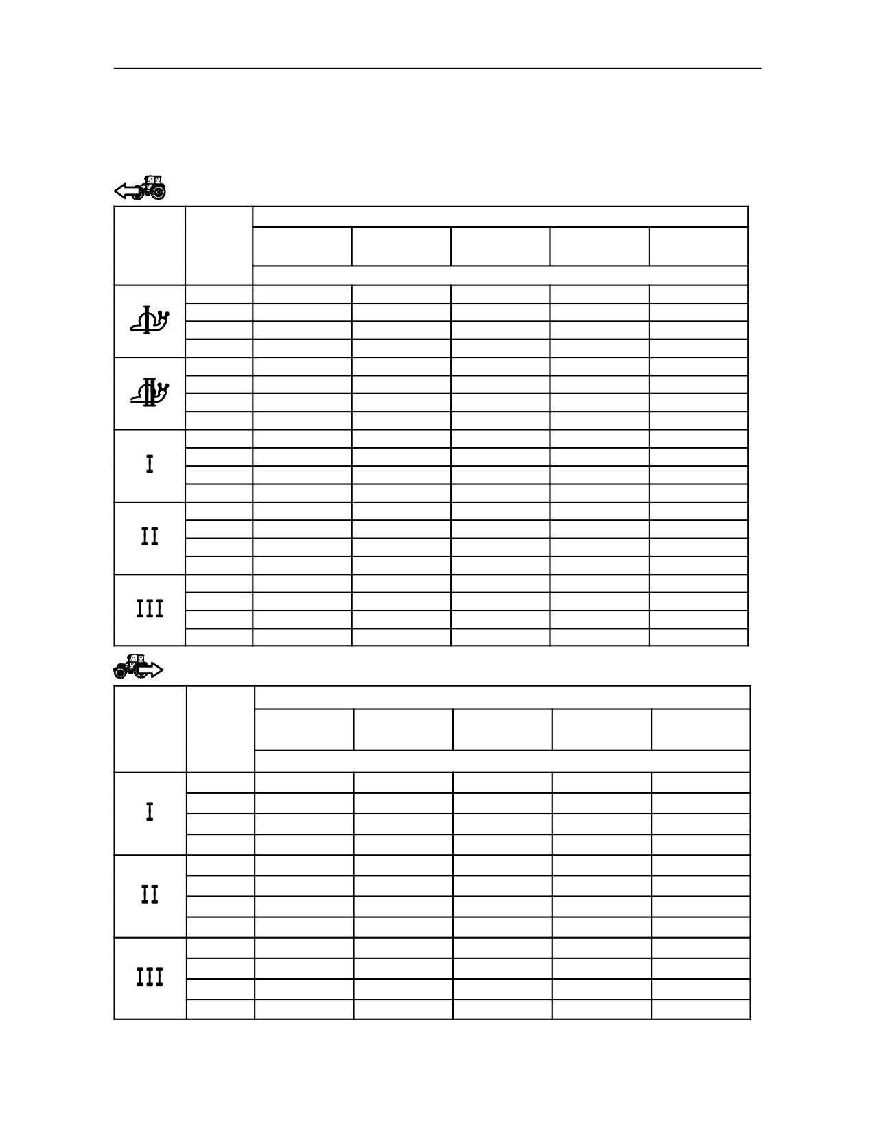
TD 60D, TD 70D, TD 80D, TD 90D and TD 95D MODELS TRACTOR SPEED IN km/h WITH
POWER TAKE--OFF RUNNING AT STANDARD SPEEDS
Creeper transmission 40 km/h (25 mph) version (20 forward gears + 12 reverse gears -- Synchro
Shuttle)
Forward gears
REAR TYRES km/h (mph)
TD 60D
TD 70D
TD 80D
TD 90D
TD 95D
RANGE
GEAR
14.9--28
14.9--30
16.9--30
18.4--30
18.4--34
750/1000 rev/min
1
0.3
(0.2)
0.4
(0.2)
0.3
(0.2)
0.4
(0.2
0.4
(0.2)
2
0.5
(0.3)
0.6
(0.4)
0.5
(0.3)
0.6
(0.4)
0.6
(0.4)
3
0.7
(0.4)
0.8
(0.5)
0.7
(0.4)
0.8
(0.5)
0.8
(0.5)
4
1.0
(0.6)
1.1
(0.7)
1.0
(0.6)
1.1
(0.7)
1.1
(0.7)
1
0.8
(0.5)
0.8
(0.5)
0.8
(0.5)
0.8
(0.5)
0.9
(0.6)
2
1.2
(0.7)
1.3
(0.8)
1.3
(0.8)
1.3
(0.8)
1.3
(0.8)
3
1.7
(1.1)
1.8
(1.1)
1.7
(1.1)
1.8
(1.1)
1.9
(1.2)
4
2.4
(1.5)
2.5
(1.6)
2.4
(1.5)
2.5
(1.6)
2.7
(1.7)
1
1.9
(1.2)
2.0
(1.2)
1.9
(1.2)
2.0
(1.2)
2.1
(1.3)
2
2.9
(1.8)
3.1
(1.9)
3.0
(1.9)
3.1
(1.9)
3.1
(1.9)
3
4.0
(2.5)
4.2
(2.6)
4.0
(2.5)
4.2
(2.6)
4.4
(2.7)
4
5.7
(3.5)
6.0
(3.7)
5.8
(3.6)
6.0
(3.7)
6.3
(3.9)
1
4.5
(2.8)
4.6
(2.9)
4.5
(2.8)
4.7
(2.9)
4.9
(3.0)
2
6.9
(4.3)
7.2
(4.5)
6.9
(4.3)
7.2
(4.5)
7.1
(4.4)
3
9.4
(5.8)
9.7
(6.0)
9.4
(5.8)
9.7
(6.0)
10.3
(6.4)
4
13.4
(8.3)
13.9
(8.6)
13.5
(8.4)
14.0
(8.7)
14.7
(9.1)
1
10.5
(6.5)
10.9
(6.8)
10.6
(6.6)
11.0
(6.8)
11.5
(7.1)
2
16.2
(10.1)
16.8
(10.4)
16.3
(10.1)
16.9
(10.5)
16.8
(10.4)
3
22.0
(13.7)
22.9
(14.2)
22.1
(13.7)
22.9
(14.2)
24.2
(15.0)
4
31.6
(19.6)
32.8
(20.4)
31.7
(19.7)
32.9
(34.6)
34.6
(21.5)
Reverse gears
REAR TYRES km/h (mph)
TD 60D
TD 70D
TD 80D
TD 90D
TD 95D
RANGE
GEAR
14.9--28
14.9--30
16.9--30
18.4--30
18.4--34
750/1000 rev/min
1
1.8
(1.1)
1.9
(1.2)
1.8
(1.1)
1.9
(1.2)
2.0
(1.2)
2
2.8
(1.7)
2.9
(1.8)
2.8
(1.7)
2.9
(1.8)
2.9
(1.8)
3
3.8
(2.4)
4.0
(2.5)
3.8
(2.4)
4.0
(2.5)
4.2
(2.6)
4
5.5
(3.4)
5.7
(3.5)
5.5
(3.4)
5.7
(3.5)
6.0
(3.7)
1
4.2
(2.6)
4.4
(2.7)
4.3
(2.7)
4.4
(2.7)
4.7
(2.9)
2
6.5
(4.0)
6.8
(4.2)
6.6
(4.1)
6.8
(4.2)
6.8
(4.2)
3
8.9
(5.5)
9.2
(5.7)
8.9
(5.5)
9.3
(5.8)
9.8
(6.1)
4
12.7
(7.9)
13.2
(8.2)
12.8
(8.0)
13.3
(8.3)
14.0
(8.7)
1
10.0
(6.2)
10.4
(6.5)
10.0
(6.2)
10.4
(6.5)
11.0
(6.8)
2
15.4
(9.6)
16.0
(9.9)
15.5
(9.6)
16.0
(9.9)
15.9
(9.9)
3
20.9
(13.0)
21.8
(13.6)
21.0
(13.0)
21.8
(13.6)
23.0
(14.3)
4
30.0
(18.6)
31.2
(19.4)
30.1
(18.7)
31.2
(19.4)
32.9
(20.4)
3--17
SECTION 3 -- FIELD OPERATIONS
HYDRAULIC LIFT
The hydraulic lift circuit uses transmission lubrication
oil which is supplied by a gear pump driven by the
1
engine shaft by means of the engine timing gears.
This lift, which can sense the forces on the lower link
arms via a torsion bar, enables the following
operations to be performed:
2
--
position control;
--
draft control;
--
float;
14
--
mixed control.
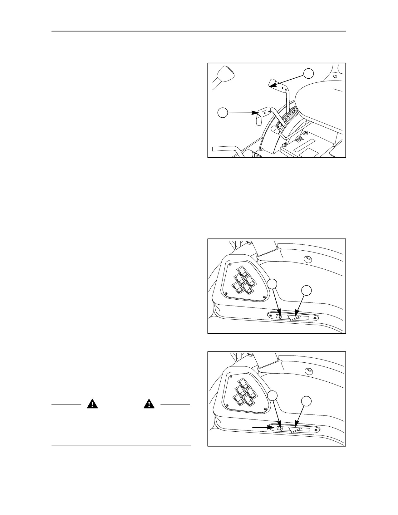
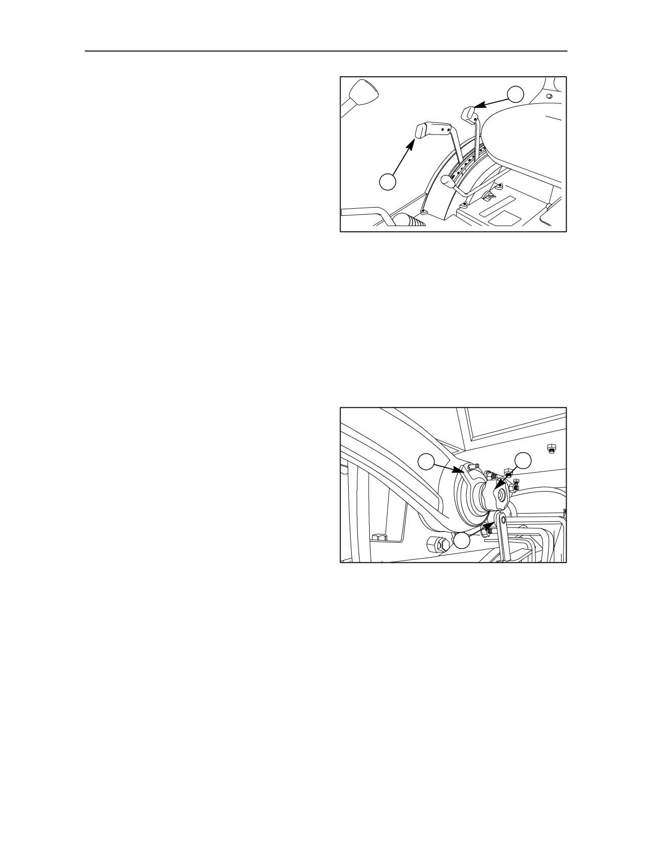
With the combined use of levers (1) and (2) fig. 14,
the user can select and operate the most suitable
mode for the implement and conditions in hand.
Lift--O--MaticTM Control switch for fully raising
and lowering the lift arms -- Fig. 15-- 16
1. Down switch
2. Up switch
2
1
To lower the implement, press switch (1) fig. 15 fully
down and the link arms will descend to the limit
previously set using the position control lever (1)
fig. 14.
To raise the implement, move the latch (2) fig. 16
15
back, in the direction of the arrow, to release the
switch (1) from its catch. The link arms will raise to
full height.
2
1
CAUTION
When working with mounted implements which are
connected to the power take--off, extend the lift rods
to their maximum length to avoid damaging the PTO
shaft when lifting using the Lift-O-MaticTM.
16
3--18
SECTION 3 -- FIELD OPERATIONS
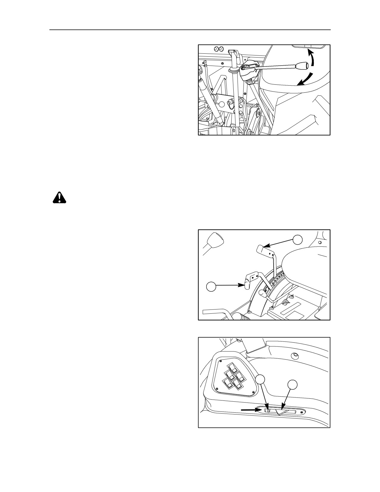
EXTERNAL LIFT LEVER -- Fig. 17
A
For operations controlled from ground level use the
external control lever (1) fig. 17, lifting the lever from
its housing.
B
--
move the lever in the direction of arrow A to lower
the link arms;
--
move in direction fo arrow B to raise the link
arms.
CAUTION: before leaving the tractor seat to operate
TRE0813A
the external control lever (1), check that:
17
--
the parking brake is applied;
--
the gear shift and range levers are in neutral;
--
the PTO is disengaged;
--
the engine is running at idle speed;
--
the draft control lever (2) fig. 18 is fully forward.
DANGER: when using lever 1, ensure no--
one is within the operating range of the imple-
ment connected to the lift. Never stand between the
implement and the rear of the tractor.
POSITION CONTROL
1
--
Move draft control lever (2) fig. 18 fully forward.
--
Set the position of the implement, either in or
above the ground, by moving the position control
2
lever (1) fig. 18 forward to lower and rearwards
to raise. The movement of the implement will be
proportional to the movement of the lever.
18
--
Press latch (2) fig. 19 in the direction of the arrow
to raise the implement at the headland. Fully
press switch (1) fig. 19 on the Lift--O--MaticTM, to
lower the implement, when required, without
having to use the lift control lever.
2
1
19
3--19
SECTION 3 -- FIELD OPERATIONS
DRAFT CONTROL
2
--
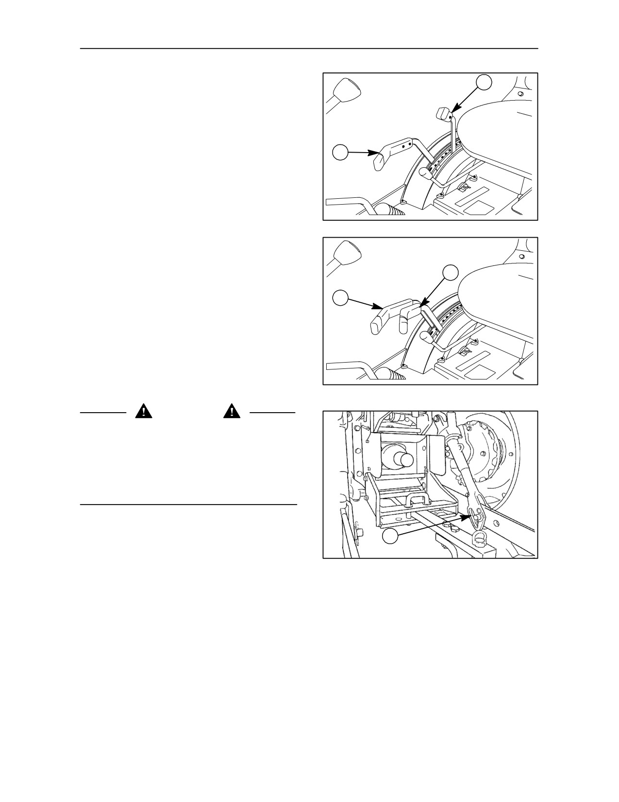
Move position control lever
(1) fig. 20
fully
forward.
--
Set the desired implement depth in the ground by
gradually moving the draft control lever (2) fig. 20
1
forward. Forward movement of the lever will
increase implement depth and rearward
movement will reduce the depth. Changes in
draft loading are sensed through the lower link
arms. The hydraulic system responds by raising
or lowering the implement to restore the original
draft setting.
20
FLOAT OPERATION
1
--
To operate the lift in float mode, i.e. to enable the
link arms to float freely, move both levers (1) and
2
(2) fig. 21 fully forward.
--
Always use the Lift--O--MaticTM controls (1) and
(2) fig. 15 to raise and lower implements at the
headland.
21
WARNING
When working in float mode, with an implement
connected to the power take--off and using the lift, to
avoid damaging the universal joint:
The lift rods must be connected to the lower
arms by inserting the pins in the slots (1) fig. 22,
thereby allowing free movement of the
implement.
1
TRE0016A
22
3--20
SECTION 3 -- FIELD OPERATIONS
MIXED CONTROL
2
--
Set the desired implement depth in the ground
and find the working depth required, as
described for draft control.
--
When the implement is set at the desired depth,
gradually move the position control lever (1)
fig. 23, until the link arms start to raise.
1
The lift operates in draft control, but at the same
time prevents the implement, if soil with less
resistance is encountered, from going too deep.
This avoids the risk of bringing soil, which is
unsuitable for crop--growing, to the surface.
23
--
To lift and lower the implement in and out of work
at the headland, always use switches (1) and (2)
fig. 19.
NOTE: Do not use levers (1) and (2) fig. 21 to raise
and lower implements as this will change the
previously set operating conditions. Use only
Lift-O-MaticTM controls
(1) and (2) fig. 19
at the
headland.
LINK UPPER LIMIT ADJUSTMENT-- Fig. 24
Adjust the lift link travel as follows:
1. connect the implement to the lift arm swivel
bushings;
2. increase engine speed to 1200 ± 1500 rev/min;
3. press the Lift--O--Matic push button (1) fig. 19 to
1
2
the fully lowered position;
4. move levers (1) and (2) fig. 23 fully forward;
5. using the position control lever, raise the
implement to the required height;
6. switch off the engine;
7. slacken knob (2) fig. 24
and turn the quadrant
3
(1) fig. 24 until it touches the roller (3) fig. 24;
TRE0817A
8. on completion of the adjustments, lock the
24
quadrant (1) by tightening the knob (2).
3--21
SECTION 3 -- FIELD OPERATIONS
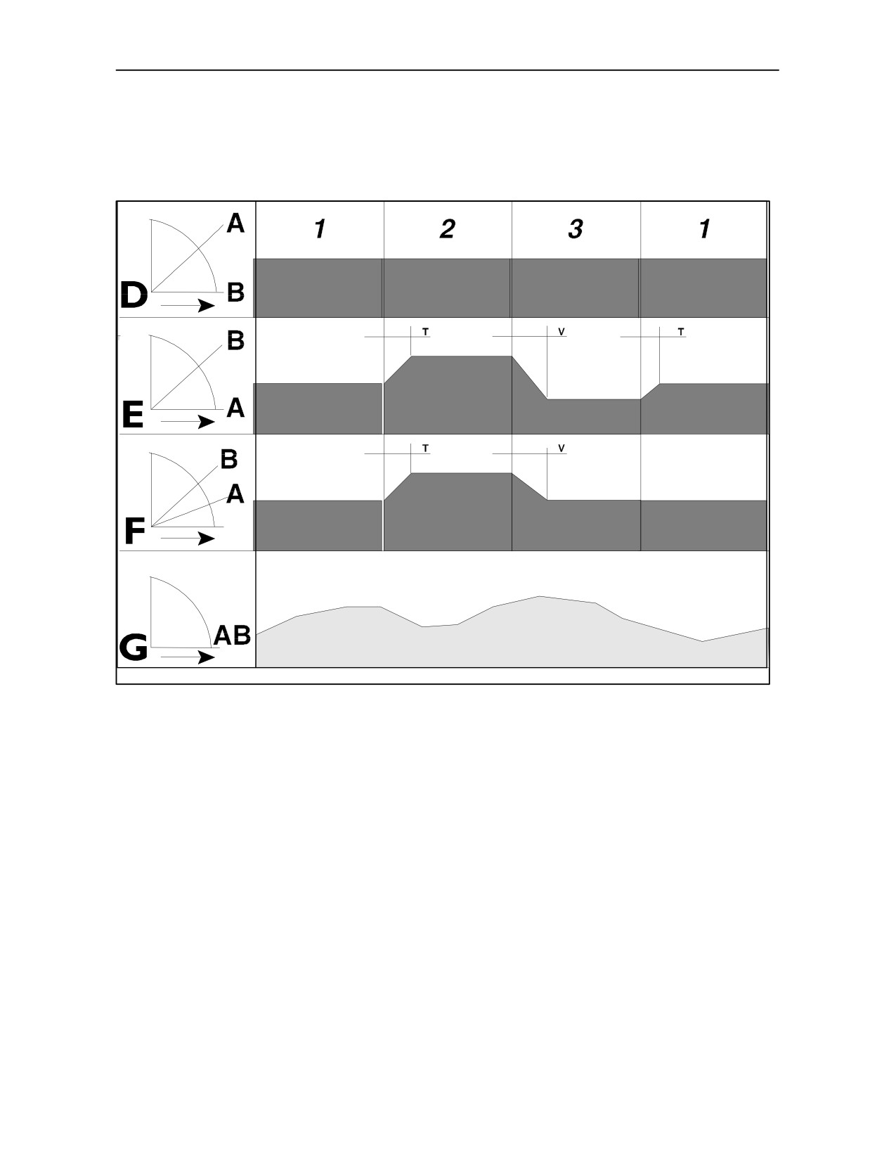
HYDRAULIC LIFT -- CONDITIONS OF USE
23793
25
A Position control lever.
1
Medium consistency soil.
B Draft control lever.
2
Sticky soil.
D Position control operation.
3
Loose soil.
E Draft control operation.
T Constant action time.
F Mixed control.
V Constant descent speed.
G Float function.
3--22
SECTION 3 -- FIELD OPERATIONS
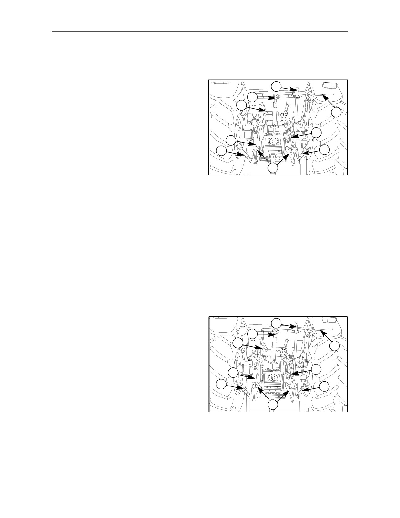
THREE -- POINT LINKAGE
(CATEGORY II)
Tractors without cabs -- Fig. 26
2
1. Adjustable length top link.
1
8
2. Right--hand lift rod adjuster, with return spring.
7
3. Right--hand lift rod.
3
4. Telescopic lateral stabilisers.
6
4
4
5. Lower links.
6. Left--hand lift rod.
5
26
7. External lift lever.
8. Top link attachment bracket.
Tractors with cabs -- Fig. 27
2
1. Adjustable length top link.
1
8
7
2. Right--hand lift rod adjuster, with return spring.
3. Right--hand lift rod.
3
6
4. Telescopic lateral stabilisers.
4
4
5. Lower links.
6. Left--hand lift rod.
TRE0818A
5
27
7. External lift lever.
8. Top link attachment bracket.
3--23
SECTION 3 -- FIELD OPERATIONS
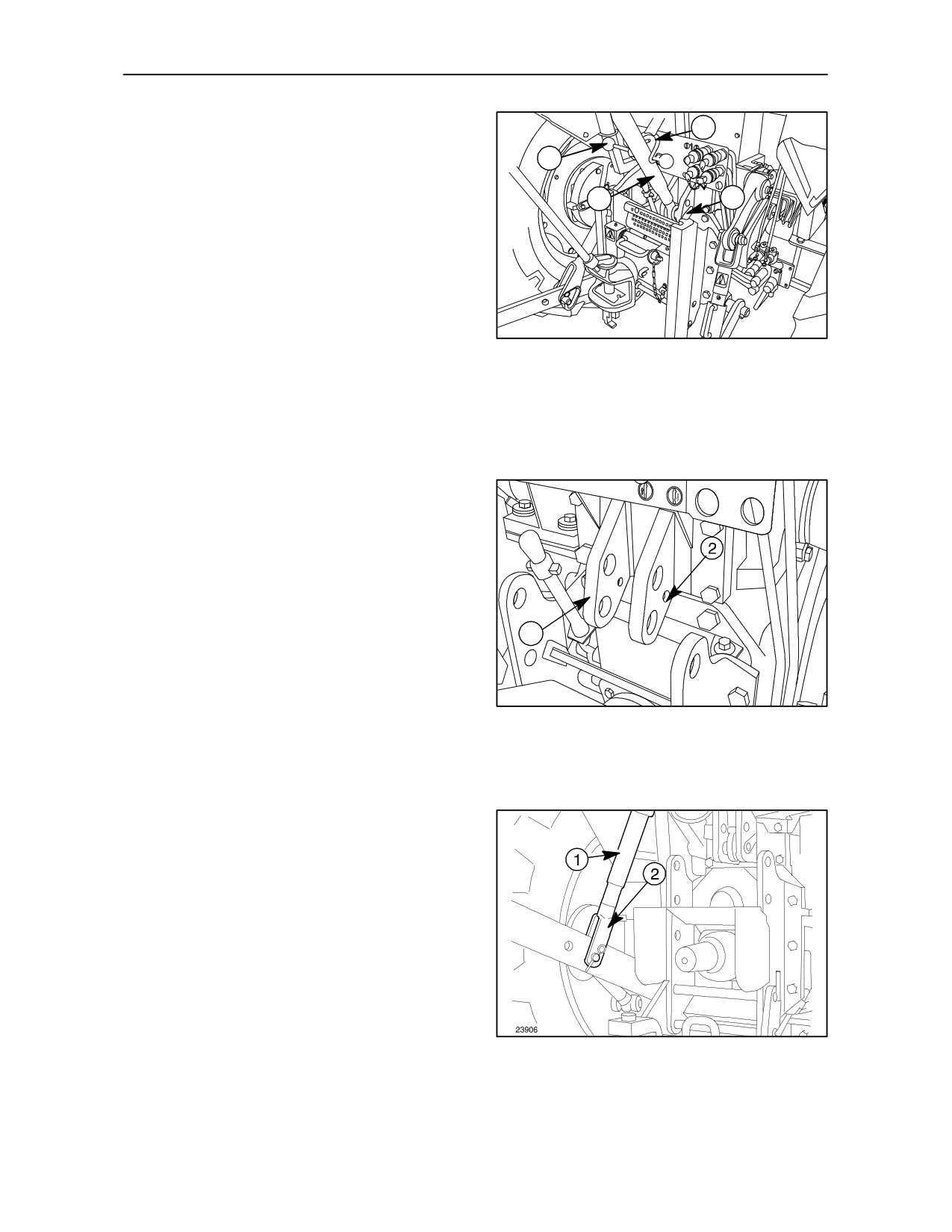
Adjustable top link -- Fig. 28
3
The top link (1) can be connected to the attachment
2
bracket via one of two holes. Select the most suitable
hole for attaching the implement.
1
4
Use the upper hole for maximum lift capacity and the
greatest implement to cab clearance. Use the lower
hole for the best ground penetration.
To adjust the top link, rotate the sleeve using the
tommy bar (2). Top link length must not exceed 870
TRE0819A
mm (34.25 in).
28
The top link can be removed or held by catch (3)
when it is not in use.
Top link attachment bracket -- Fig. 29
NOTE: When the top link retaining pin (4) fig. 28 is
inserted, ensure that the safety tang on the end of the
retaining pin is in the smaller hole (2) fig. 29.
1
TRE0820A
29
Left--hand lift rod -- Fig. 30
Adjust the length of lift rod
(1) by tightening or
unscrewing the lower end (2). Adjust the rod length
as necessary so that the implement can be set in its
working position parallel to the ground.
30
3--24
SECTION 3 -- FIELD OPERATIONS
Chain type stabilisers -- Fig. 31
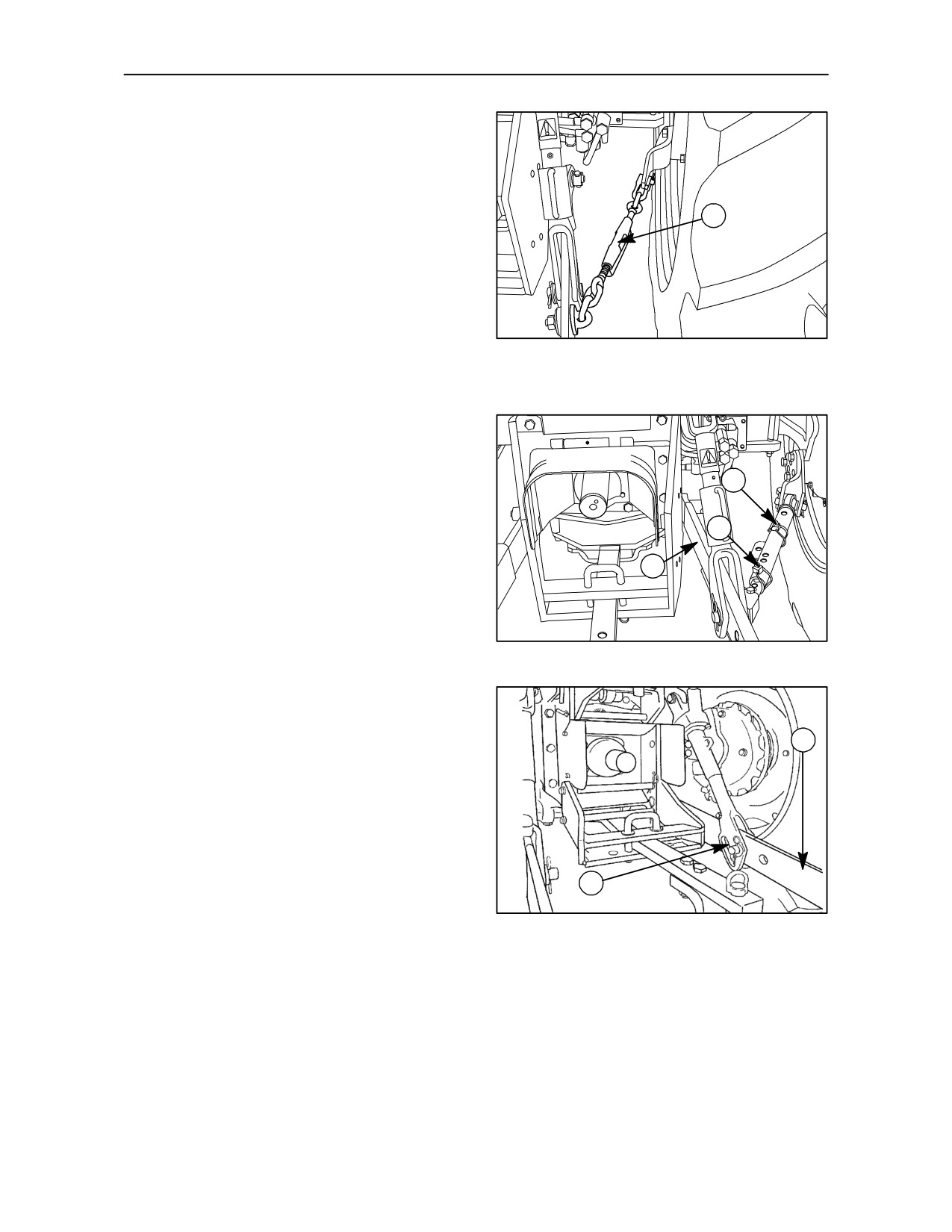
Rotate the sleeve (1) to adjust the stabiliser length.
1
TRE0821A
31
Telescopic stabilisers -- Fig. 32-- 33
To adjust the stabiliser length, proceed as follows:
1
--
remove pin (1) to allow free lateral swing of the
2
arms (3);
--
adjust the opening of the arms (3) by positioning
3
the pin (2) in one of the free holes on the sleeve.
TRE0801A
32
NOTE: Adjust the lateral stabiliser struts, fig. 32, so
that the lateral movement of the lower links (1)
fig. 33, does not exceed 120 mm (4.72 in) each side.
1
NOTE: Limited free movement of the lower links (1)
fig. 33 can be obtained by connecting the retaining
pins through the slots (2) fig. 33. This is particularly
useful when working with wide implements (harrows,
2
cultivators, etc.).
TRE0016A
33
3--25
SECTION 3 -- FIELD OPERATIONS
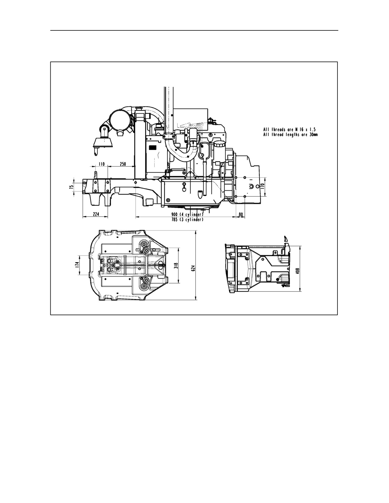
EQUIPMENT MOUNTING POINTS
TD 60D, TD 70D, TD 80D and TD 90D Models
TRE0859A
34
Both sides of the tractor are equipped with threaded
NOTE: Use exclusively the holes specified in fig. 34
holes for connecting implements and auxiliary
when mounting auxiliary equipment. .
equipment.
The use of different holes for auxiliary applications
automatically exonerates New Holland from all
The figure shows the free fixing holes on the
liability in relation to damage vehicle or injury to
left--hand side of the tractor, which are identical and
persons, resulting from failure to observe the relative
symmetrical to the fixing holes on the right--hand
regulations.
side.
3--26
SECTION 3 -- FIELD OPERATIONS
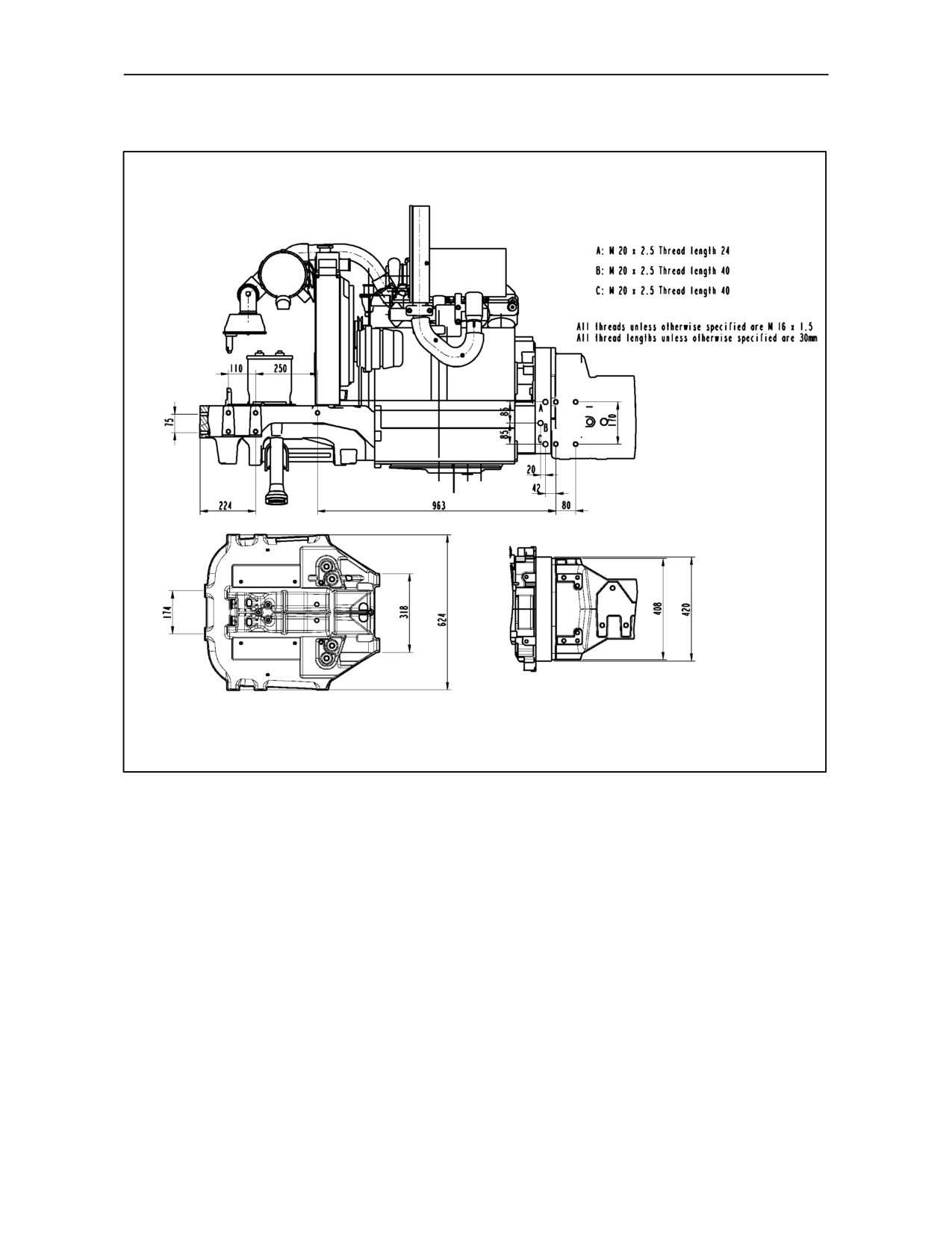
EQUIPMENT MOUNTING POINTS
TD 95D Model
TRE0860A
35
Both sides of the tractor are equipped with threaded
NOTE: Use exclusively the holes specified in fig. 35
holes for connecting implements and auxiliary
when mounting auxiliary equipment. .
equipment.
The use of different holes for auxiliary applications
automatically exonerates New Holland from all
The figure shows the free fixing holes on the
liability in relation to damage vehicle or injury to
left--hand side of the tractor, which are identical and
persons, resulting from failure to observe the relative
symmetrical to the fixing holes on the right--hand
regulations.
side.
3--27
SECTION 3 -- FIELD OPERATIONS
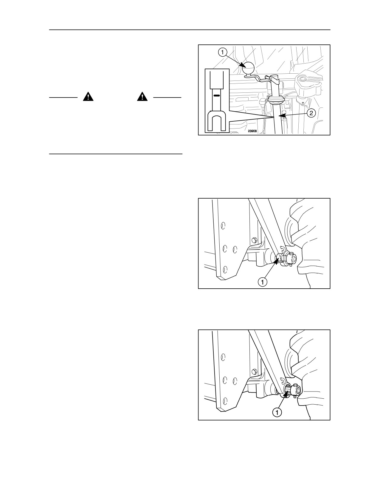
Right--hand vertical lift rod adjustment
(on--board adjustment) -- Fig. 36
The right--hand vertical lift rod (2) can be adjusted
using knob (1) fig. 36 which can also be operated
from the driving seat.
MAX
WARNING
When extending the length of the right hand lift rod
do not increase length beyond the MAX mark.
The weight of the implement could forcibly pull the
sleeve (2) fig. 36 from the rod.
The length limit is shown by the MAX mark that
corresponds with the maximum extension point on
36
the rod.
LOWER LINK ATTACHMENT
For light work -- Fig. 37
When operating the tractor in draft or mixed control,
install the lower links (5) figs. 26 and 27 with the
spacers (1) fig. 37 fitted to the inner face of the lower
links. This will provide greater lift sensitivity when
working with light equipment or light draft loads.
24252
37
For normal and heavy work -- Fig. 38
When operating the tractor in draft or mixed control,
fit the spacers (1) fig. 38 to the outer face of the lower
links for normal or heavy work.
This position, which reduces lift sensitivity, is
recommended for medium to heavy implements or
draft loads.
The figures illustrate the most suitable positions for
the above operations.
24253
38
3--28
SECTION 3 -- FIELD OPERATIONS
Conversion Category I to Category II --
Fig. 39
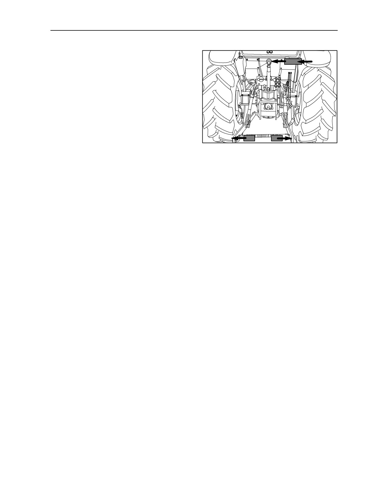
To allow both Cat I and Cat II categories equipment
to be used, the three--point linkage has:
--
one 7.4 inches (19 cm) inside diameter bushing
(1) for Cat I implements, to be inserted in the
spherical bushing at the end of the top link;
--
a series of 8.6 inches (22 cm) inside diameter
bushings (2) for Cat I implements, to be inserted
in the spherical bushings at the ends of the lower
lift arms.
TRE0822A
39
For Cat II equipment given values are namely
10
inches
(25.4
cm) and
11
inches
(28
cm)
approximately.
3--29
SECTION 3 -- FIELD OPERATIONS
REMOTE CONTROL VALVES
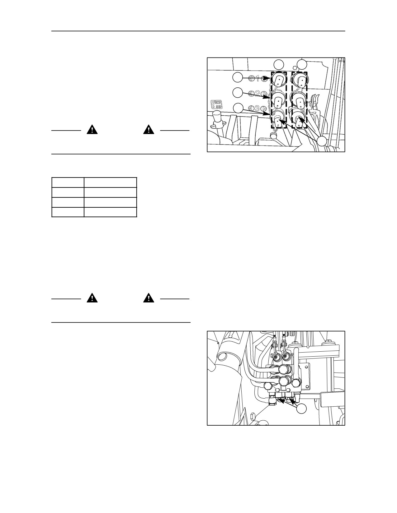
QUICK--FIT COUPLERS -- Fig. 40
B
C
One, two or three control valves (which use the same
oil circuit as the hydraulic lift), can be fitted to your
1
tractor for remote control of single--acting and
double--acting cylinders.
2
Each valve has two slide lock type female1/2 in.
couplers which can be connected with pressurised
3
male couplers. You can thus connect the control
cylinder lines with two hands.
WARNING
The couplers have no breakaway capability with the
A
hoses in them.
TRE0854A
40
Valves and their colours are shown at Figures:
40
and 43.
Valve no:
Colour
1.
Green
2.
Blue
3.
Brown
Remote outlets shown in Fig. 40 on left side (line B)
is used to retract the cylinder, on right side (line A) is
used to extend the cylinder.
Before fitting and releasing the hoses, first slide the
collar of female couplers, but only after first:
--
switching off the engine;
--
lowering any implements connected to the lift;
--
thoroughly cleaning the two parts to be
connected.
WARNING
When not using the female couplers, protect them
with plastic caps (A) fig. 40.
SINGLE--ACTING/DOUBLE--ACTING
SWITCHING -- Fig. 41
To switch the control valves to:
--
Single--acting, slacken screw (1) fig. 41 near to
the valve control lever pivot until it stops.
--
Double--acting, fully tighten (1) fig. 41.
When using single acting, in order to accelerate the
identification of the coupler to which the implement
is to be connected, actuate the valve lever and
1
observe the two lines to which the couplers are
connected: the line carrying the oil should move.
TRE0824A
For greater safety, check that the line to which the
41
implement connected using single acting is on the
valve body that connected furthest from the change
over screw.
3--30
SECTION 3 -- FIELD OPERATIONS
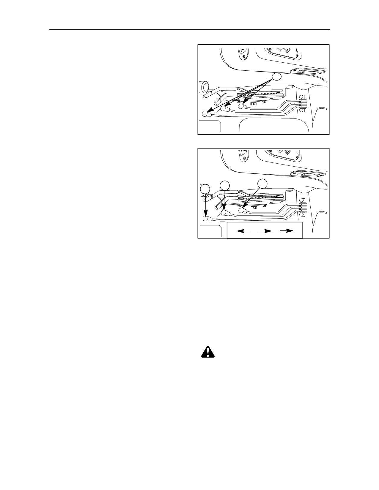
1, 2, 3. Valve control levers for
single--acting or double--acting cylinders
-- Fig. 42
These levers can be used in two positions or in the
1
central neutral position:
— forward = down;
— back = up.
42
VALVES WITH FLOAT SETTING
(OPTIONAL)
Your tractor can be fitted with valves with a float
setting for implements requiring this function.
3
2
To select the float setting, push the relevant valve
1
lever fully forward, past the first detent.
A mechanical detent will keep the lever engaged in
the float setting.
To release the control lever from the float setting,
simply pull it up into its rest position.
A
B
C
D
43
CONTROL VALVE LEVERS FOR SINGLE
CONTROL VALVE LEVERS FOR SINGLE
OR DOUBLE--ACTING CYLINDERS WITH
OR DOUBLE--ACTING CYLINDERS--Fig. 43
KICK--OUT (not for all markets) -- Fig. 43
There are four possible positions :
All positions are available on fig. 43
for kick--out
--
position A = lever (1) back (raise implement);
applications.
--
position B = neutral position;
--
position A = lever (1) back (lower implement);
--
position C = lever (1) forward (lower implement);
--
position C = lever (1) forward (raise implement);
--
position D = lever (1) fully forward in float setting.
Neutral position B and position D are the same as
In this position the cylinder can extend or retract
explained previously.
freely, allowing the implement to follow the land
Valves with the kick--out feature, the lever will
contours (not for all markets). Lever remains in
automatically return to neutral position (B) when the
position that used.
hydraulic cylinder has reached the end of its stroke.
CAUTION: leaks of pressurised hydraulic
Valves with the kick--out feature, are factory adjusted
to a pressure of 120(+10/--0) bar.
fluid can penetrate the skin and cause
When a single acting valve is used, the automatic
severe injuries:
release mechanism works only when lifting.
--
Never use your hands to locate a leak -- use
NOTE: A detent will hold the lever in the selected
cardboard or paper.
raise or lower position until the remote cylinder
--
Switch off the engine and bleed the pressure
reaches the end of the stroke when the control lever
before connecting or disconnecting pressurised
will automatically return to neutral. Alternatively, the
lines.
lever may be returned to neutral manually. The lever
will not return automatically from the float position.
--
Tighten all connectors before starting the engine
or pressurising the hydraulic system.
NOTE: When the valve is used as single acting, the
automatic release mechanism works only when
If fluid penetrates the skin, seek medical assistance
lifting.
immediately to prevent serious injury.
3--31
SECTION 3 -- FIELD OPERATIONS
WHEEL TRACK ADJUSTMENT
FRONT WHEEL TRACKS 2WD
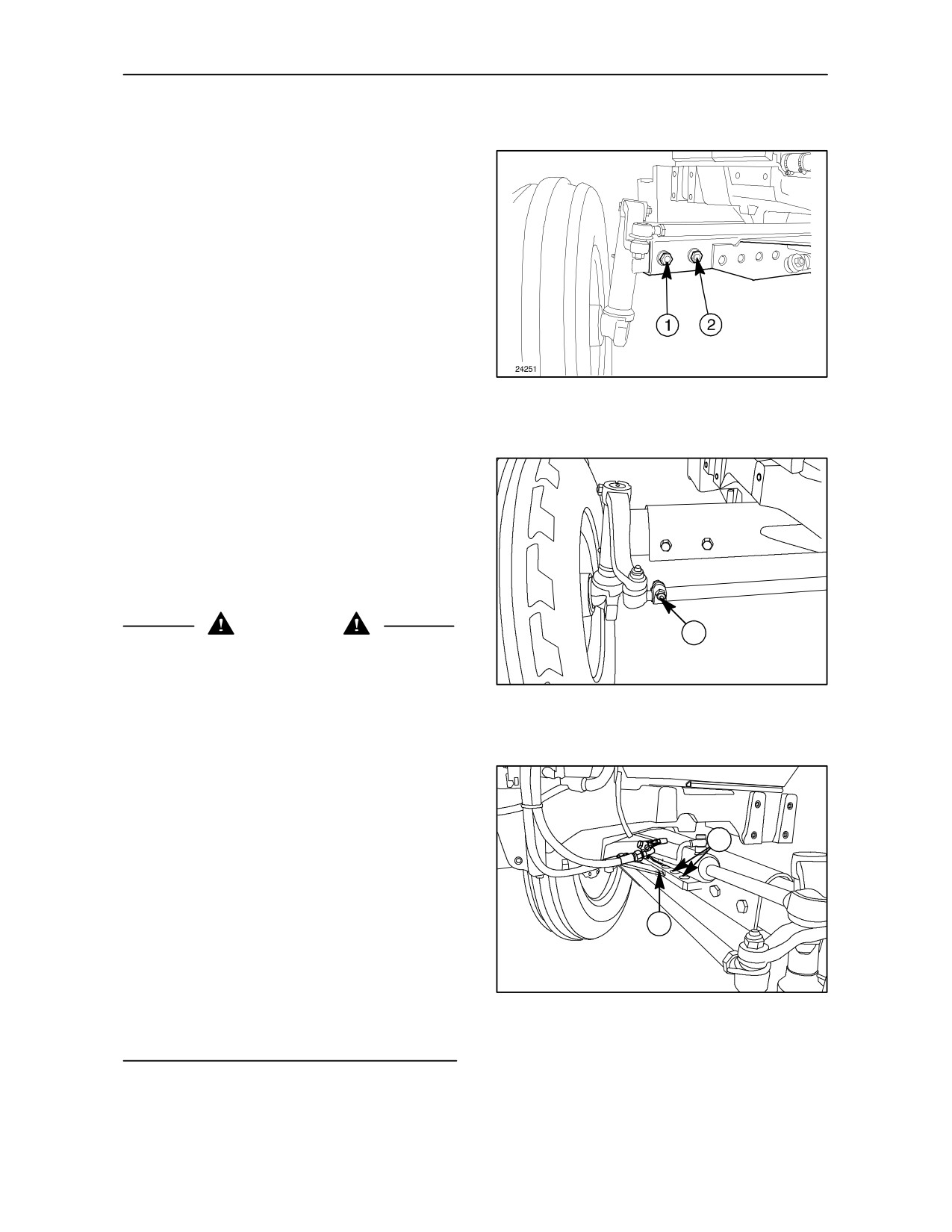
To adjust the front wheel track, proceed as follows:
--
raise the front of the tractor using a jack
positioned in the middle of the axle;
--
release the sliding ends after removing the
retaining bolts and nuts (1) and (2) fig. 44, two on
each side
(tightening torque: 220 Nm - 22.5 kgm);
--
adjust the length of the steering rods connecting
44
the two wheels by removing the locking screws
(3) fig. 46 (tightening torque: 39 Nm - 4 kgm);
--
this provides seven possible wheel tracks, as
illustrated in fig. 47.
A further larger track width (maximum track) can be
obtained by reversing the wheels on their hubs. Only
use this maximum track where absolutely necessary.
The tightening torque of the wheel to hub locknuts is
115 Nm (11.7 kgm).
WARNING
3
If the tractor has hydrostatic steering, proceed as
described above for the left--hand wheel. For the
TRE0825A
right--hand wheel, however, after releasing the
sliding end of the axle, you must change the
45
hydraulic cylinder’s internal angle, as appropriate, in
the following way:
--
slacken the cylinder hose connectors;
--
keep screw (3) fig. 45
loosened;
--
insert angle adjuster pin (1) fig. 46 in one of the
2
corresponding holes (2) fig. 46.
--
tighten the pin
(tightening torque: 294 Nm - 30 kgm)
1
--
tighten screw (3) fig. 46
(tightening torque: 39 Nm -- 4 kgm).
TRE0826A
--
check that the hoses are not twisted and tighten
46
the connectors.
3--32
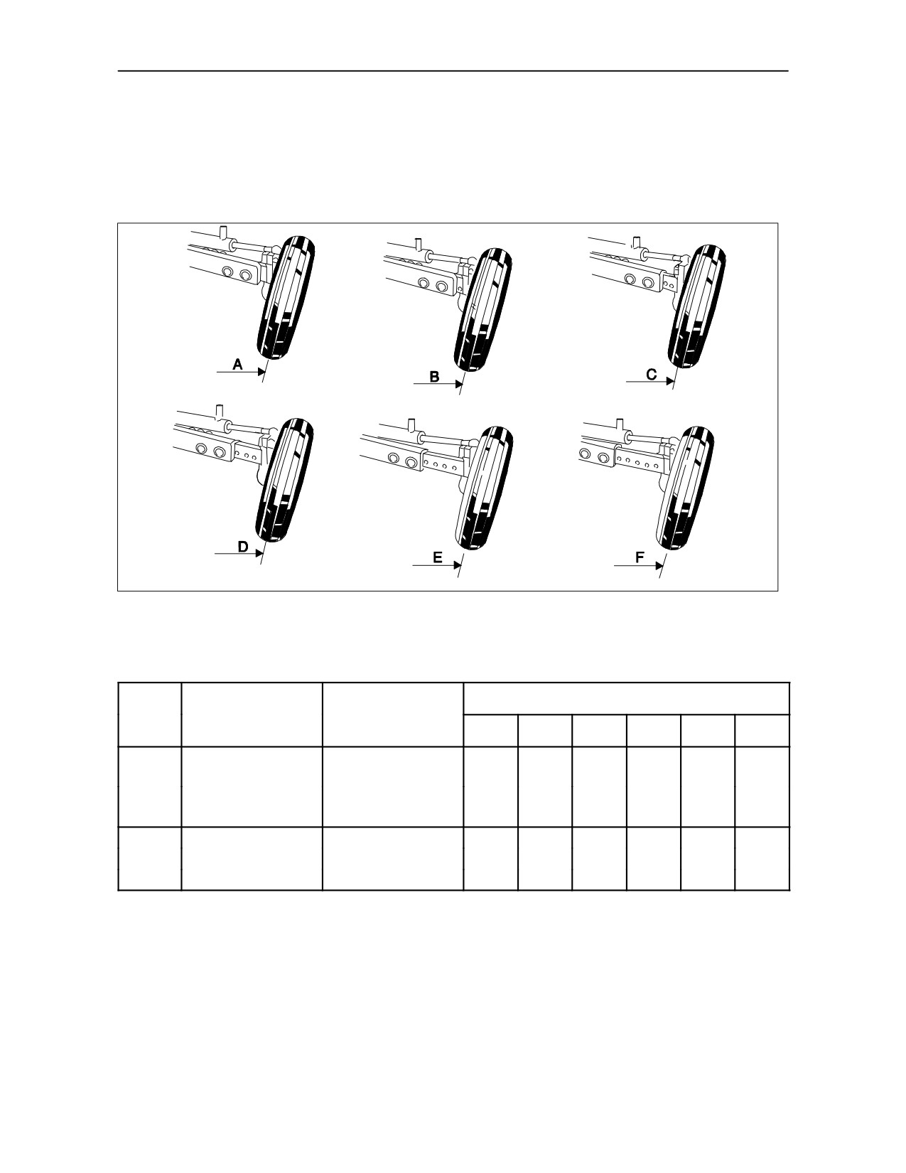
SECTION 3 -- FIELD OPERATIONS
Illustration of front wheel tracks, 2--wheel drive
23928B
47
Wheel tracks mm (in)
Standard wheel
Model
Tyre dimensions
track mm (in)
A
B
C
D
E
F
TD 60D
1400
6.00--16
1500
1600
1700
1800
1900
1500
(59)
7.50--16
(55)
(59)
(63)
(67)
(71)
(75)
TD 70D
TD 80D
7.50 -- 16
1410
1510
1610
1710
1810
1910
7.50 -- 18
1510
(59)
TD 90D
(56)
(59)
(63)
(67)
(71)
(75)
TD 95D
7.50 -- 18
3--33
SECTION 3 -- FIELD OPERATIONS
WHEEL TRACK ADJUSTMENT FRONT
WHEEL TRACKS, 4--WHEEL DRIVE AND
REAR WHEEL TRACKS, 2 AND 4--WHEEL
DRIVE
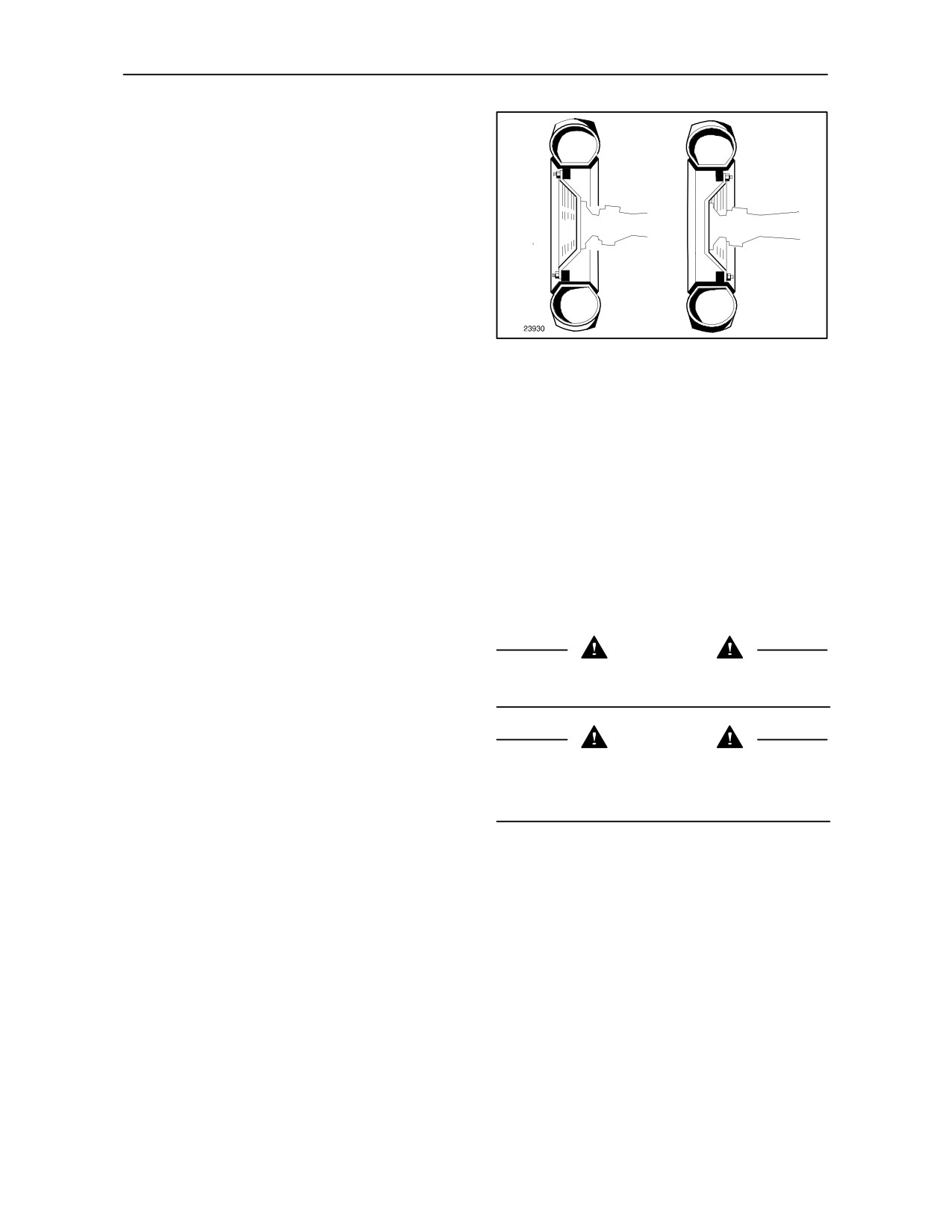
The front wheels can be fitted with the concave
surface of the disc facing inwards or outwards
(see fig. 48).
Tracks of different sizes can be obtained using both
these disc positions, as illustrated in figs. 49 and 50.
48
When adjusting the wheel track, ensure that the
points of the tyre treads are still facing the direction
of forward travel, indicated by an arrow on the tyre
walls.
Always check that the front and rear wheels are
symmetrically aligned in relation to the tractor’s
longitudinal axis.
Front wheels 4WD
The tightening torque of the hub disc locknuts is 255
Nm -- 26 kgm (187.98 lb.ft), and the torque of the rim
disc locknuts is 216 Nm -- 22 kgm (159.06 lb.ft).
Rear wheels 2/4WD
WARNING
Select the appropriate rear track before changing the
The tightening torque of the hub disc locknuts is 255
front one.
Nm -- 26 kgm (187.98 lb.ft), and that for the rim disc
locknuts is 245 Nm -- 25 kgm (180.75 lb.ft).
DANGER
Always check that the front and rear wheels are
When removing the wheels, proceed with extreme
symmetrically aligned relative to the tractor’s
caution, use suitable means to lift the tractor and
longitudinal axis.
specified equipment to move heavy parts.
3--34
SECTION 3 -- FIELD OPERATIONS
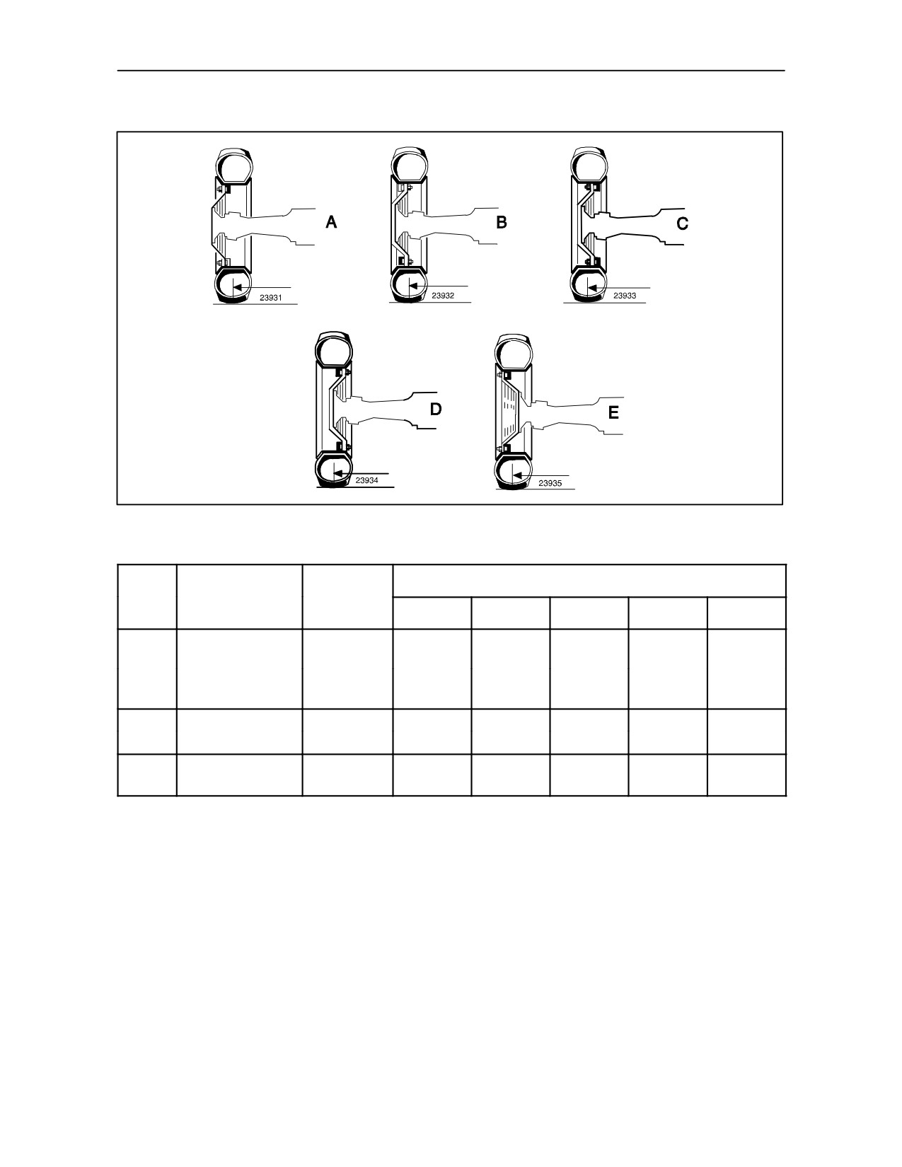
WHEEL TRACK DIAGRAM FRONT 4WD
49
Standard
Wheel tracks mm (in)
Model
Tyre dimensions
wheel track
mm (in)
A
B
C
D
E
TD 60D
11.2--20
1450
1550
1650
1750
1880
1450
(57)
(57)
(61)
(65)
(69)
(74)
TD 70D
9.50--24
TD 80D
11.2--24
1550
1650
1750
1850
1980
1550
(61)
TD 90D
12.4--24
(61)
(65)
(69)
(73)
(78)
13.6--24
1650
1750
1850
1980
TD 95D
1650
(65)
--
14.9--24
(65)
(69)
(73)
(78)
NOTE: Under the EC regulations, the maximum
permissible overall width for tractors equipped with
standard tail--lights is 2150 mm. With wheels set at
maximum track width, the maximum overall width
obtainable is 2315 mm for machines with ROPS, and
2510 mm for machines with cab. If these wider
settings are adopted, the tail--lights must be mounted
to special extendible arms (available on request) so
that they can be adjusted to indicate the overall width
of the tractor.
3--35
SECTION 3 -- FIELD OPERATIONS
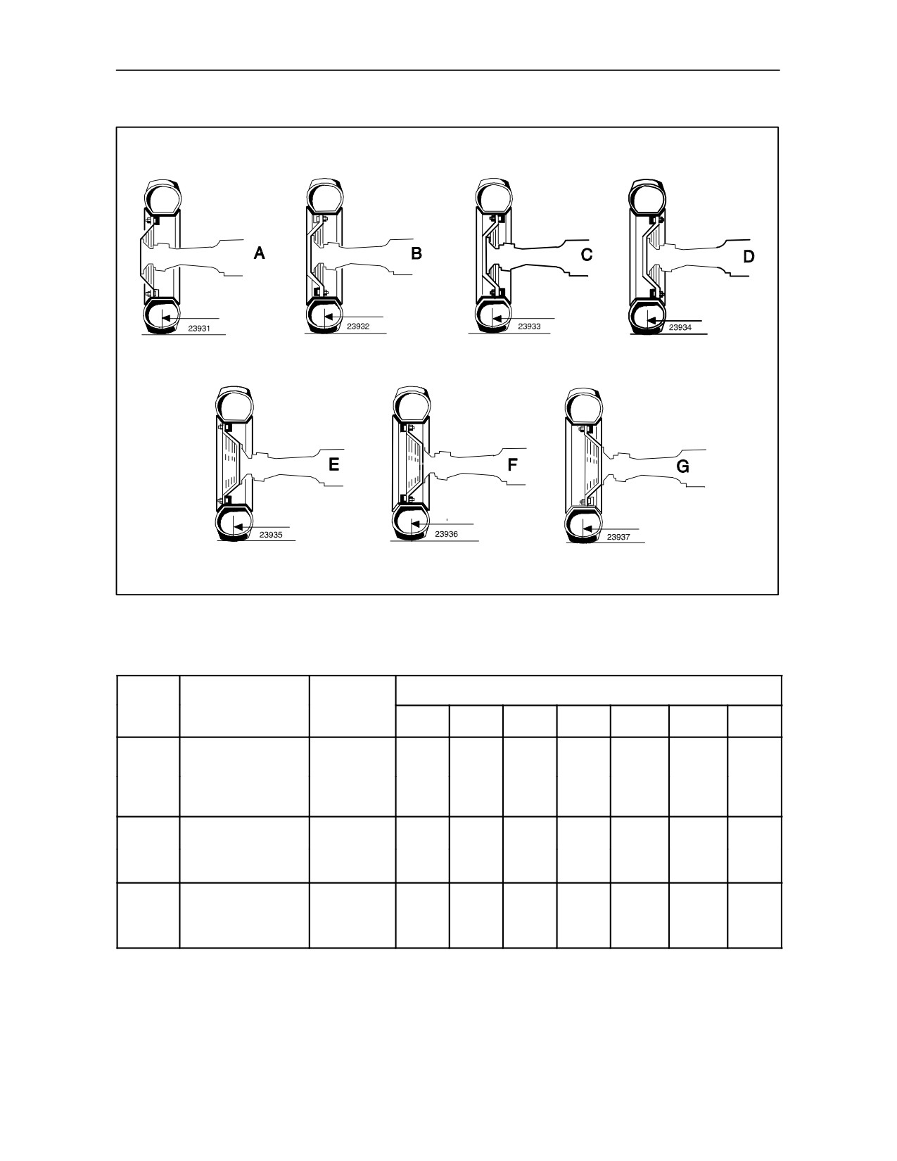
WHEEL TRACK DIAGRAM REAR 2WD / 4WD
50
Standard
Wheel tracks mm (in)
Model
Tyre dimensions
wheel track
mm (in)
A
B
C
D
E
F
G
14.9 -- 28
TD 60D
1425
1525
1625
1725
1825
1925
14.9
-- 30
1425
(56)
--
(56)
(60)
(64)
(68)
(72)
(76)
TD 70D
16.9 -- 30
13.6 -- 38
TD 80D
1420
1520
1620
1720
1820
1920
2020
16.9
-- 34
1420
(56)
TD 90D
(56)
(59)
(64)
(67)
(72)
(75)
(80)
18.4 -- 30
16.9 -- 34
1525
1625
1725
1825
1925
2025
TD 95D
18.4 -- 30
1525
(60)
--
(60)
(64)
(68)
(72)
(76)
(80)
18.4 -- 34
3--36
SECTION 3 -- FIELD OPERATIONS
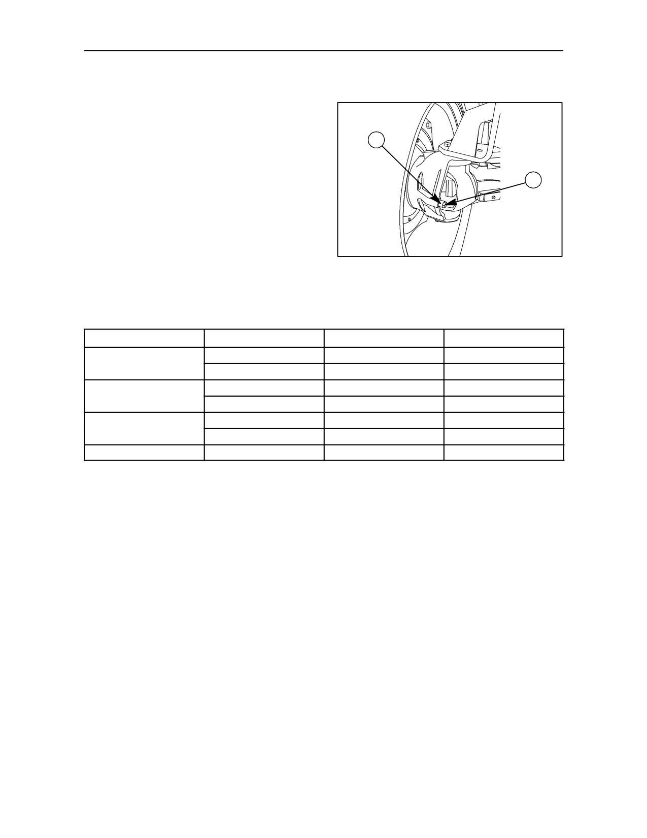
STEERING ANGLE ADJUSTMENT
When using the narrowest tracks, the tyres may
touch the tractor with the wheels on full lock and
when the front axle is at maximum pivot position -- for
example, in deep ploughing when enter and exit the
2
furrows.
To avoid this problem, the axle has a steering stop
screw and a spacer which can be adjusted so as to
1
obtain the optimum steering angle for each wheel
track.
Turning angle can be adjusted between 40° -- 45°
and 50° by remowing screw (1) and spacer (2)
fig. 51, on the front axle of all models.
TRE0827A
According to tire size and track width, adjustment
51
possibilities are shown at table below:
Tyre Size
Track Width (mm)
Steering Angle (°)
Positions*
1560
40
A
11.2R--28
1671
50
C
1562
40
A
12.4R--24
1674
50
C
1674
45
B
13.6R--24
1760
50
C
360/70R--24
1624
50
C
* Position A: Both screw and spacer installed.
* Position B: Only screw installed, without spacer.
* Position C: Both screw and spacer removed.
3--37
SECTION 3 -- FIELD OPERATIONS
STEERING ANGLE ADJUSTMENT (Models with
2nd steering cylinder)
When using the narrowest tracks, the tyres may
touch the tractor with the wheels on full lock and
when the front axle is at maximum pivot position -- for
example, in deep ploughing when enter and exit the
furrows.
To avoid this problem, the axle has a steering stop
screw which can be adjusted so as to obtain the
optimum steering angle for each wheel track.
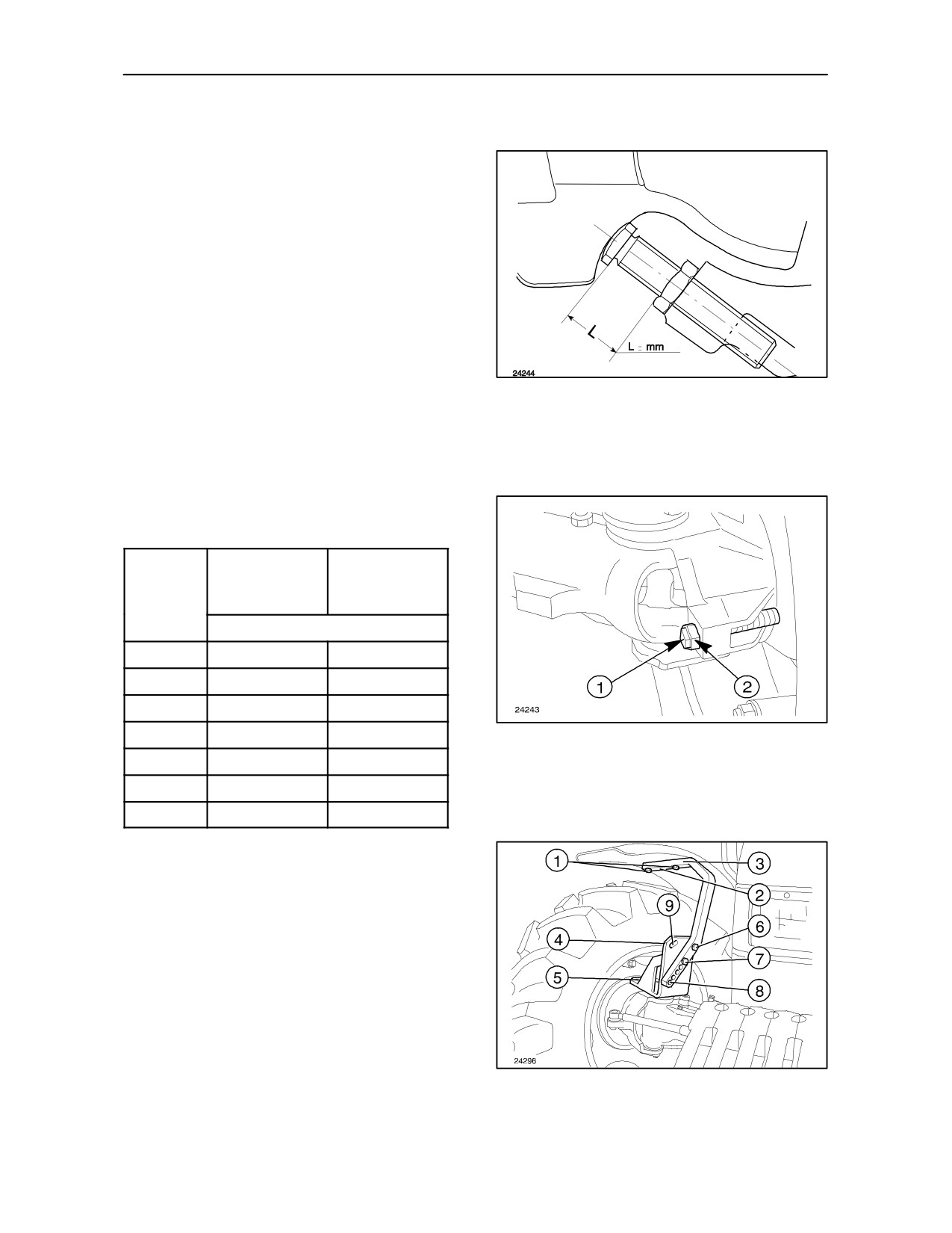
To adjust the steering angle, refer to figs. 52 and 53
and proceed as follows :
--
Turn the wheels;
--
Slacken the locknut (2) and adjust the projection
of stop screw (1) as shown;
52
--
After adjustment, secure the stop screw (1) with
the locknut (2).
NOTE: Subsequent to adjustment of the steering
angle make sure that, with the wheels at full lock,
there is at least 20 mm (0.8 in) clearance between the
tractor fairing and the tyre (or the mudguard, if fitted).
Refer to table below for optimum steering angles :
TD 60D,
TD 90D,
TD 70D,
Steering
TD 95D models
angles (°)
TD 80D models
L (mm)
25
57
63
30
47
53
35
37
42
40
28
32
53
45
19
21
50
9
11
55
0
0
FRONT MUDGUARDS 4WD -- Fig. 54
(optional)
The following adjustments can be made to the front
mudguards, to suit the tyres and track setting:
Horizontal adjustment :
--
loosen screws (1) and attach to holes (2) on
support bracket (3). Alternatively, relocate the
bolts (5) securing the base (4) to the front axle.
Vertical adjustment :
--
loosen screws (6) and (7) and adjust the height,
attaching the mudguard to the holes (8).
Rotation :
54
--
loosen screw (7), remove screw (6) and insert in
one of the two slots (9).
3--38
SECTION 3 -- FIELD OPERATIONS
TYRES
USE, MAINTENANCE AND REPLACEMENT
• When changing tyres, select suitable tyres for
• Have the tyres checked by a specialist if one or
the actual tractor use, taking account of the
more of the problems previously explained
recommended combinations on pages 3--43 and
should occur.
3--44.
•
Do not exceed the permitted load shown on the
tyres themselves.
• Consult an expert if a tyre is subject to violent
shocks even if there are no visible signs of
damage.
•
Do not exceed the speeds shown on the tyres, as
in addition to overheating, this causes premature
wear of the tyres.
• Tyres age even if little used or not used at all.
Cracks on the walls, sometimes accompanied by
bulges, are a sign of ageing.
•
Do not fit used tyres where their previous use is
unknown.
Ask your authorised dealer or a tyre specialist for
• Tyres fitted on tractors which are not used for
advice.
extended periods tend to age more rapidly than
those used more often. In this event, it is
advisable to raise the tractor from the ground and
protect the tyres from direct sunlight.
•
After fitting tyres, check that the wheel nuts for
tightness after 100 km (60 miles) or 3 hours in
operation.
Thereafter, check that they are tight on a regular
basis.
WARNING
•
Do not stand tyres on hydrocarbons (oil, diesel,
Tyres must be changed by skilled personnel who
grease, etc.).
have the right equipment and technical knowledge.
If tyres are replaced by unskilled personnel, serious
•
The tyres fitted on your tractor must be checked
physical injuries can result, serious damage to the
periodically, paying particular attention to:
tyres can be caused and the actual wheel rim can be
distorted..
--
the tread, which should wear uniformly;
--
the walls, which must not have cracks,
bulges or abrasions.
3--39
SECTION 3 -- FIELD OPERATIONS
LOADING INFORMATION
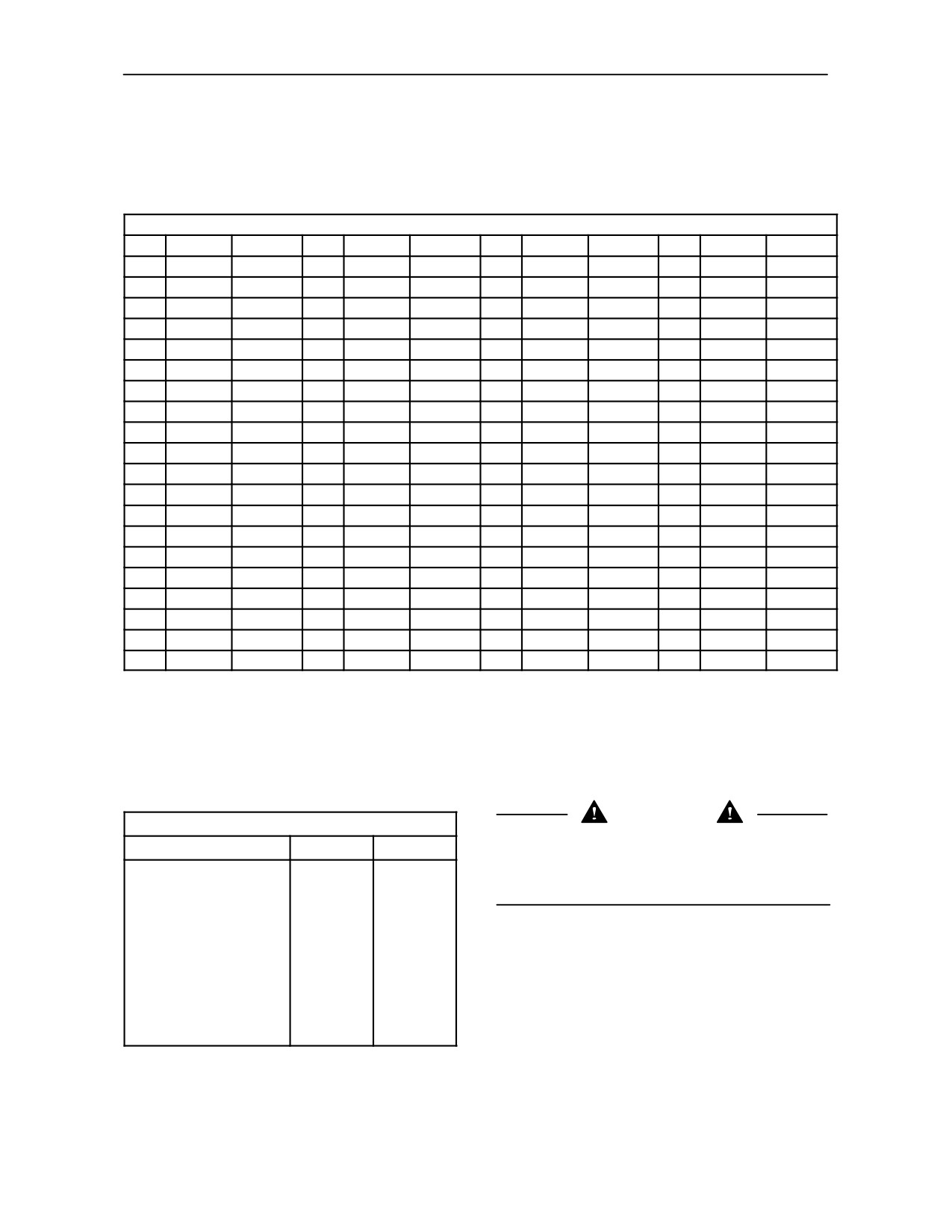
The loading index (LI) is a numerical index indicating the maximum permissible load on the tyre for the speed
indicated by the relevant speed code in the conditions specified by the tyre manufacturer.
Loading index per wheel
LI
kg
lbs
LI
kg
lbs
LI
kg
lbs
LI
kg
lbs
100
800
1768
120
1400
3094
140
2500
5525
160
4500
9945
101
825
1823
121
1450
3204
141
2575
5691
161
4625
10221
102
850
1878
122
1500
3315
142
2650
5856
162
4750
10497
103
875
1934
123
1550
3425
143
2725
6022
163
4875
10774
104
900
1989
124
1600
3536
144
2800
6188
164
5000
11050
105
925
2045
125
1650
3646
145
2900
6409
165
5150
11381
106
950
2099
126
1700
3757
146
3000
6630
166
5300
11731
107
975
2155
127
1750
3867
147
3075
6796
167
5450
12044
108
1.000
2210
128
1800
3978
148
3150
6961
168
5600
12376
109
1.030
2276
129
1850
4088
149
3250
7182
169
5800
12818
110
1.060
2343
130
1900
4199
150
3350
7403
170
6000
13260
111
1.090
2409
131
1950
4309
151
3450
7624
171
6150
13591
112
1.120
2475
132
2000
4420
152
3550
7842
172
6300
13923
113
1.150
2541
133
2060
4553
153
3650
8066
173
6500
14365
114
1.180
2608
134
2120
4685
154
3750
8287
174
6700
14807
115
1.215
2685
135
2180
4818
155
3875
8564
175
6900
15249
116
1.250
2762
136
2240
4950
156
4000
8840
176
7100
15691
117
1.285
2840
137
2300
5083
157
4125
9116
177
7300
16133
118
1.320
2917
138
2360
5216
158
4250
9392
178
7500
16575
119
1.360
3006
139
2430
5370
159
4375
9669
179
7750
17127
SPEED CODE
The speed code indicates the speed at which the tyre can transport a load corresponding to its loading index
in the conditions specified by the manufacturer:
Speed code
WARNING
Respecting the limits in the tables will ensure that the
SYMBOL
km/h
mph
tyres both perform well and are long--lasting.
A1
5
3
Overloading tyres substantially reduces their service
A2
10
6
life.
A3
15
9
A4
20
12
A5
25
16
A6
30
19
A7
35
22
A8
40
25
B
50
31
C
60
37
NOTE: The values in these tables are also marked
D
65
40
on the walls of the tyres themselves.
3--40
SECTION 3 -- FIELD OPERATIONS
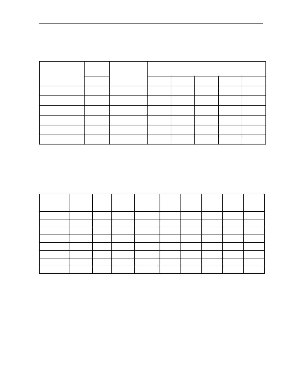
TYRE DATA AND PRESSURES
FRONT WHEELS 2WD
( X )= AVAILABLE
(NA) = NOT AVAILABLE
Ply rating
Model
(PR)
Tyres
Rim size
8
TD60D
TD70D
TD80D
TD90D
TD95D
6.00--16
X
4.00E--16
X
X
NA
NA
NA
7.50--16
X
5.50E--16
X
X
X
NA
NA
7.50--18
X
5.50E--18
NA
NA
X
X
X
7.50--20
X
5.50E--20
NA
NA
NA
X
X
9.00--16
X
W8--16
NA
NA
X
X
X
10.00--16
X
W8--16
X
X
X
X
X
FRONT TYRES 4WD MODELS
Max.
Speed
Loading
Tyres
Rim size
pressure
TD60D
TD70D
TD80D
TD90D
TD95D
code
index
bar (Psi)
11.2R--20
W9--20
A8
116
1.4
(20.3)
X
X
NA
NA
NA
11.2R--24
W10--24
A8
119
1.4
(20.3)
X
X
X
NA
NA
12.4R--20
11X20
A8
116
1.4
(20.3)
X
X
NA
NA
NA
360/70R--20
11X20
A8
120
1.6
(23.2)
X
X
NA
NA
NA
13.6R--24
W12--24
A8
121
1.6
(23.2)
NA
NA
X
X
X
360/70R--24
W10--24
A8
122
1.6
(23.2)
NA
NA
X
X
X
320/70R--24
W10X24
A8
116
1.4
(20.3)
NA
NA
X
NA
NA
12.4R--24
W10--24
A8
119
1.6
(23.2)
NA
NA
X
X
X
3--41
SECTION
3 -- FIELD OPERATIONS
REAR TYRES 2/4WD
Max.
Model
Speed
Tyres
Rim size
pressure
code
bar (Psi)
TD60D
TD70D
TD80D
TD90D
TD95D
14.9R--28
W13--28
A8
1.6
(23.2)
X
X
NA
NA
NA
14.9R--30
W13--30
A8
1.6
(23.2)
X
X
X
NA
NA
12.4R--36
W11--36
A8
1.6
(23.2)
X
X
NA
NA
NA
13.6R--36
W11--36
A8
1.6
(23.2)
NA
NA
X
NA
NA
16.9R--28
W15--28
A8
1.6
(23.2)
X
X
NA
NA
NA
16.9R--30
DWW15L--30
A8
1.6
(23.2)
X
X
X
NA
NA
480/70R--30
DWW15L--30
A8
1.6
(23.2)
NA
NA
X
NA
NA
420/70R--30
DWW13--30
A8
1.6
(23.2)
X
X
NA
NA
NA
18.4R--30
DWW15L--30
A8
1.6
(23.2)
NA
NA
X
X
X
13.6R--38
DWW12--38
A8
1.6
(23.2)
NA
NA
X
X
X
16.9R--34
A8
1.6
(23.2)
NA
NA
X
X
X
480/70R--34
DWW15L--34
A8
1.6
(23.2)
NA
NA
NA
X
X
18.4R--34
A8
1.6
(23.2)
NA
NA
NA
NA
X
3--42

SECTION 3 -- FIELD OPERATIONS
TYRE COMBINATIONS
RECOMMENDED COMBINATIONS 2WD
( X ) = AVAILABLE
(NA) = NOT AVAILABLE
Model
Front tyres
Rear tyres
TD60D
TD70D
TD80D
TD90D
TD95D
6.00--16
14.9R--28
X
X
NA
NA
NA
7.50--16
14.9R--28
X
X
NA
NA
NA
7.50--16
12.4R--36
X
X
NA
NA
NA
7.50--16
14.9R--30
X
X
X
NA
NA
7.50--16
16.9R--28
X
X
NA
NA
NA
7.50--16
16.9R--30
X
X
X
NA
NA
7.50--16
420/70R--30
X
X
NA
NA
NA
7.50--18
13.6R--36
NA
NA
X
NA
NA
7.50--18
18.4R--30
NA
NA
X
X
X
7.50--18
480/70R--30
NA
NA
X
NA
NA
7.50--18
13.6R--38
NA
NA
X
X
X
9.00--16
16.9R--34
NA
NA
X
X
X
7.50--20
480/70R--34
NA
NA
NA
X
X
9.00--16
480/70R--34
NA
NA
NA
X
X
7.50--20
18.4R--34
NA
NA
NA
NA
X
9.00--16
18.4R--34
NA
NA
NA
NA
X
3--43

SECTION 3 -- FIELD OPERATIONS
RECOMMENDED COMBINATIONS 4WD
( X ) = AVAILABLE
(NA) = NOT AVAILABLE
Model
Front tyres
Rear tyres
TD60D
TD70D
TD80D
TD90D
TD95D
11.2R--20
14.9R--28
X
X
NA
NA
NA
11.2R--24
12.4R--36
X
X
NA
NA
NA
12.4R--20
16.9R--28
X
X
NA
NA
NA
11.2R--24
16.9R--30
X
X
X
NA
NA
360/70R--20
420/70R--30
X
X
NA
NA
NA
12.4R--24
18.4R--30
NA
NA
X
X
X
360/70R--24
18.4R--30
NA
NA
X
X
X
320/70R--24
480/70R--30
NA
NA
X
NA
NA
12.4R--24
13.6R--38
NA
NA
X
X
X
13.6R--24
16.9R--34
NA
NA
X
X
X
360/70R24
480/70R34
NA
NA
NA
X
X
12.4R--20
14.9R--30
X
X
NA
NA
NA
12.4R--24
13.6R--36
NA
NA
X
NA
NA
13.6R--24
18.4R--34
NA
NA
NA
NA
X
3--44
SECTION 3 -- FIELD OPERATIONS
TYRE PRESSURES FOR FOUR--WHEEL DRIVE MODELS
NOTE -- pressures are expressed in bar (Psi)
TD
60D AND TD 70D MODELS
Tyre combinations
Tyre pressures 30/40 km/h (19/25 mph)
GOOD YEAR
Front
Rear
Front
Rear
11.2R--20
14.9R--28
1.4(20.3)
1.4(20.3)
11.2R--24
12.4R--36
1.5(21.8)
1.4(20.3)
12.4R--20
14.9R--30
1.4(20.3)
1.4(20.3)
12.4R--20
16.9R--28
1.4(20.3)
1.4(20.3)
11.2R--24
16.9R--30
1.5(21.8)
1.4(20.3)
360/70R20
420/70R30
1.4(20.3)
1.2(17.4)
TD
80D MODEL
Tyre combinations
Tyre pressures 30/40 km/h (19/25 mph)
GOOD YEAR
Front
Rear
Front
Rear
11.2R--24
16.9R--30
1.5
(21.8)
1.4
(20.3)
12.4R--24
13.6R--36
1.4
(20.3)
1.5
(21.8)
12.4R--24
18.4R--30
1.4
(20.3)
1.4
(20.3)
360/70R24
18.4R--30
1.4
(20.3)
1.4
(20.3)
320/70R24
480/70R30
1.2
(17.4)
1.2
(17.4)
12.4R--24
13.6R--38
1.4
(20.3)
1.4
(20.3)
13.6R--24
16.9R--34
1.2
(17.4)
1.6
(23.2)
3--45
SECTION 3 -- FIELD OPERATIONS
TYRE PRESSURES FOR FOUR--WHEEL DRIVE MODELS
NOTE -- pressures are expressed in bar (Psi)
TD
90D MODEL
Tyre combinations
Tyre pressures 30/40 km/h (19/25 mph)
GOOD YEAR
Front
Rear
Front
Rear
360/70R24
18.4R--30
1.4
(20.3)
1.2
(17.4)
12.4R--24
13.6R--38
1.4
(20.3)
1.4
(20.3)
12.4R--24
18.4R--30
1.4
(20.3)
1.4
(20.3)
13.6R--24
16.9R--34
1.5
(21.8)
1.5
(21.8)
360/70R24
480/70R34
1.2
(17.4)
1.4
(20.3)
TD
95D MODEL
Tyre combinations
Tyre pressures 30/40 km/h (19/25 mph)
GOOD YEAR
Front
Rear
Front
Rear
12.4R--24
18.4R--30
1.4
(20.3)
1.4
(20.3)
360/70R24
18.4R--30
1.4
(20.3)
1.4
(20.3)
12.4R--24
13.6R--38
1.2
(17.4)
1.6
(23.2)
360/70R24
480/70R34
1.2
(17.4)
1.4
(20.3)
14.9R--24
18.4R--34
1.4
(20.3)
1.4
(20.3)
13.6R--24
16.9R--34
1.5
(21.8)
1.5
(21.8)
3--46
SECTION 3 -- FIELD OPERATIONS
TYRES (NOT AVAILABLE ON ALL MARKETS)
( X ) = AVAILABLE
(NA) = NOT AVAILABLE
FRONT TYRES 2WD
Model
Ply
Tyres
Rating
TD60D
TD70D
TD80D
TD90D
TD95D
9.5L--15 F2
6
X
X
X
NA
NA
10.00--16 F2
8
NA
NA
X
X
X
FRONT TYRES 4WD
Model
Ply
Tyres
Rating
TD60D
TD70D
TD80D
TD90D
TD95D
8.3--24
6
X
X
NA
NA
NA
11.2--24
6
X
X
X
NA
NA
12.4--24
6
NA
NA
X
X
X
13.6 --24
8
NA
NA
NA
X
NA
14.9--24
8
NA
NA
NA
NA
X
3--47
SECTION 3 -- FIELD OPERATIONS
TYRE COMBINATIONS (NOT AVAILABLE ON ALL MARKETS)
( X ) = AVAILABLE
(NA) = NOT AVAILABLE
RECOMMENDED COMBINATIONS 2WD
Model
Front tyres
Rear tyres
TD60D
TD70D
TD80D
TD80D
TD95D
14.9--28
X
X
NA
NA
NA
9.5L
-15 F2
16.9--30
X
X
X
NA
NA
18.4--30
NA
NA
X
X
X
10.00--16 F2
18.4--34
NA
NA
NA
NA
X
16.9--34
NA
NA
NA
X
NA
RECOMMENDED COMBINATIONS 4WD
Model
Front tyres
Rear tyres
TD60D
TD70D
TD80D
TD90D
TD95D
8.3--24
14.9--28
X
X
NA
NA
NA
11.2R--24
16.9--30
X
X
X
NA
NA
12.4 R--24
18.4--30
NA
NA
X
X
X
14.9--24
18.4--34
NA
NA
NA
NA
X
13.6--24
16.9--34
NA
NA
NA
X
NA
3--48
SECTION 3 -- FIELD OPERATIONS
TYRE PRESSURES
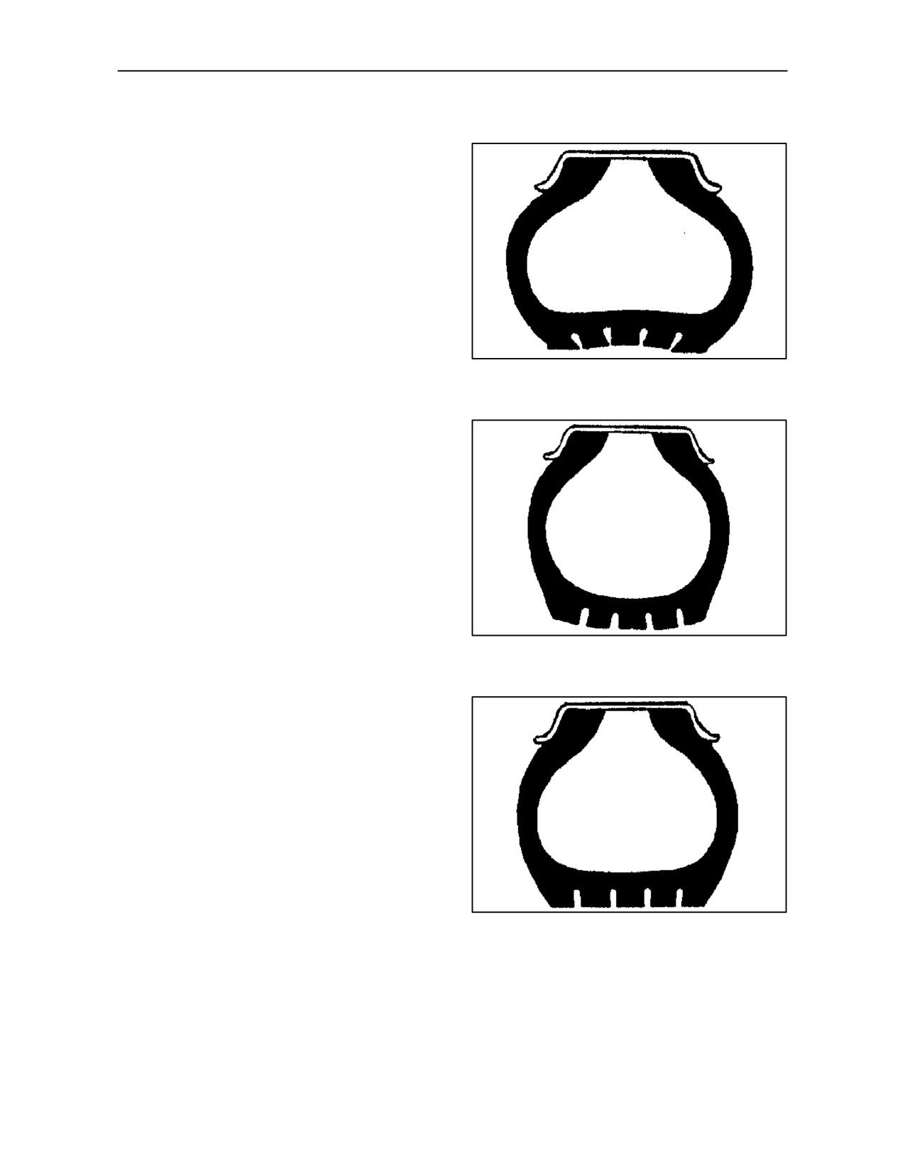
For safe use of tyres with a long service, it is
extremely important to observe the following
instructions.
• Ensure the correct pressures for each axle and
for the tyre type.
PRESSURE
TOO LOW
• Ensure tyre pressures are not lower than the
correct values, to prevent overheating of the
tyres, which can lead to:
55
--
tyre wear;
--
beading wear;
--
internal damage;
PRESSURE
--
irregular wear and short service life.
TOO HIGH
• Do not over--inflate the tyres as this can make
them more susceptible to damage in the event of
impact and, in extreme conditions, the tyre rim
can be deformed or the tyre can burst.
56
• At least once every two weeks, check the tyre
pressures, especially when liquid ballast is used.
Tyre pressures should be checked only when the
tyres are cold, as pressures rise during use, as
a result of the tyres heating up.
Tyres can be assumed to be cold if they have not
been used for at least one hour, or have not
CORRECT
covered more than two to three kilometres.
PRESSURE
Never reduce tyre pressures when the tyres are
hot.
• When you check tyre pressures, never leaveany
part of the body in the path of the valve
mechanism or cap.
57
3--49
SECTION 3 -- FIELD OPERATIONS
BALLASTING
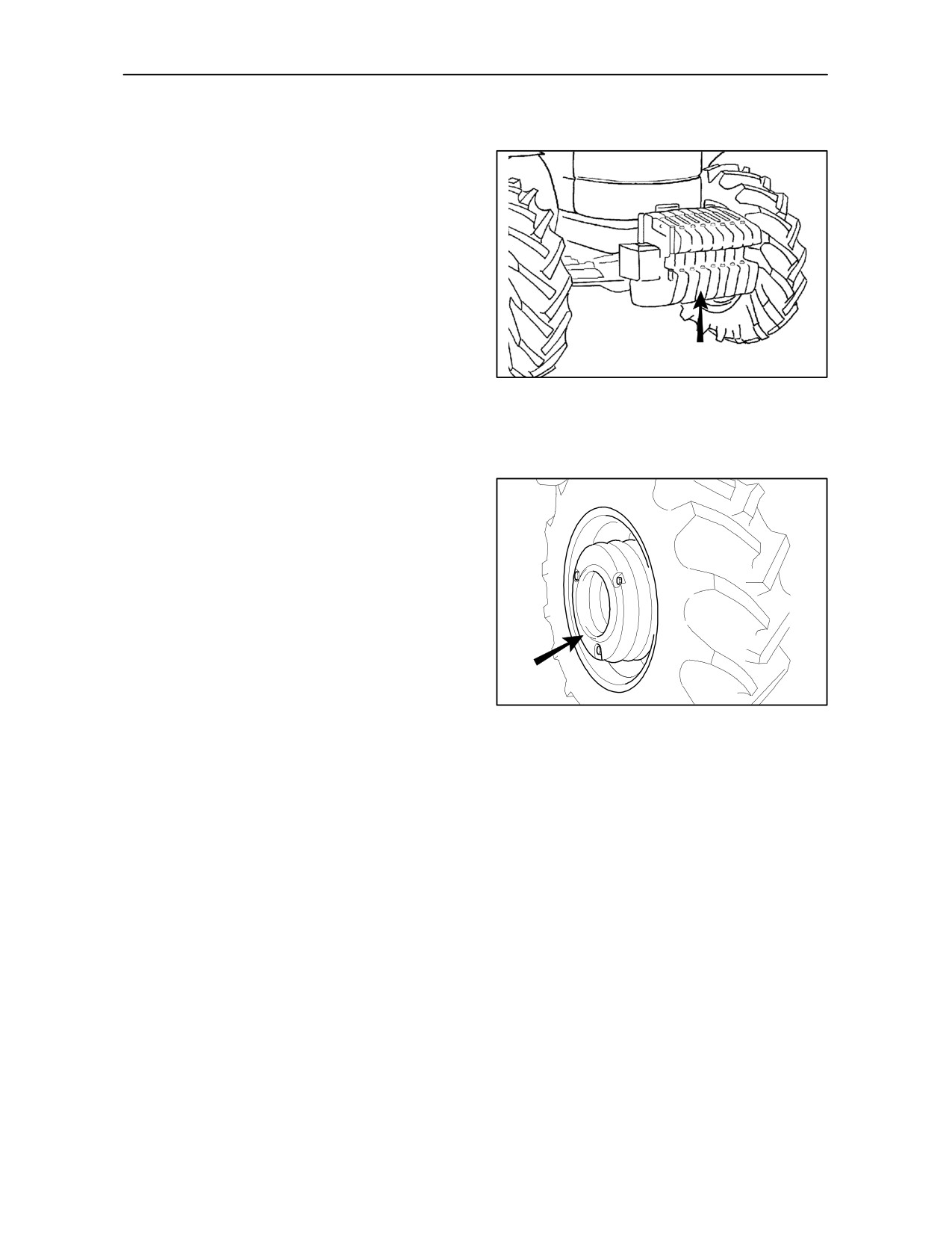
CAST IRON BALLASTING
If your tractor requires high traction power, the drive
wheels may slip due to insufficient grip on the ground,
causing loss of power and speed, increased fuel
consumption and premature tyre wear. We therefore
advise fitting cast--iron rings as ballast on the drive
wheels, or ballasting wheels with cast--iron discs or
water as described on page 3--53 and 3--54. When
using very long and heavy implements which could
affect the longitudinal stability of the tractor, ballast
the front axle by fitting the appropriate cast--iron
counterweights.
TRE0023A
58
Front end weights -- Fig. 58
4, 6, 8 or 10 cast--iron counterweights with handles,
each weighing 40 kg (88 lbs) and support bracket
weighing 80 kg (176 lbs), for a total of 240 kg (528
lbs), 320 kg (705 lbs), 400 kg (880 lbs) or 480 kg
(1058 lbs).
Rear wheel weights -- Fig. 59
4 or 6 cast--iron rings, each weighing 50 kg (110 lbs),
for a total of 200 kg (440 lbs) or 300 kg (660 lbs).
24011
59
3--50
SECTION 3 -- FIELD OPERATIONS
LIQUID BALLASTING
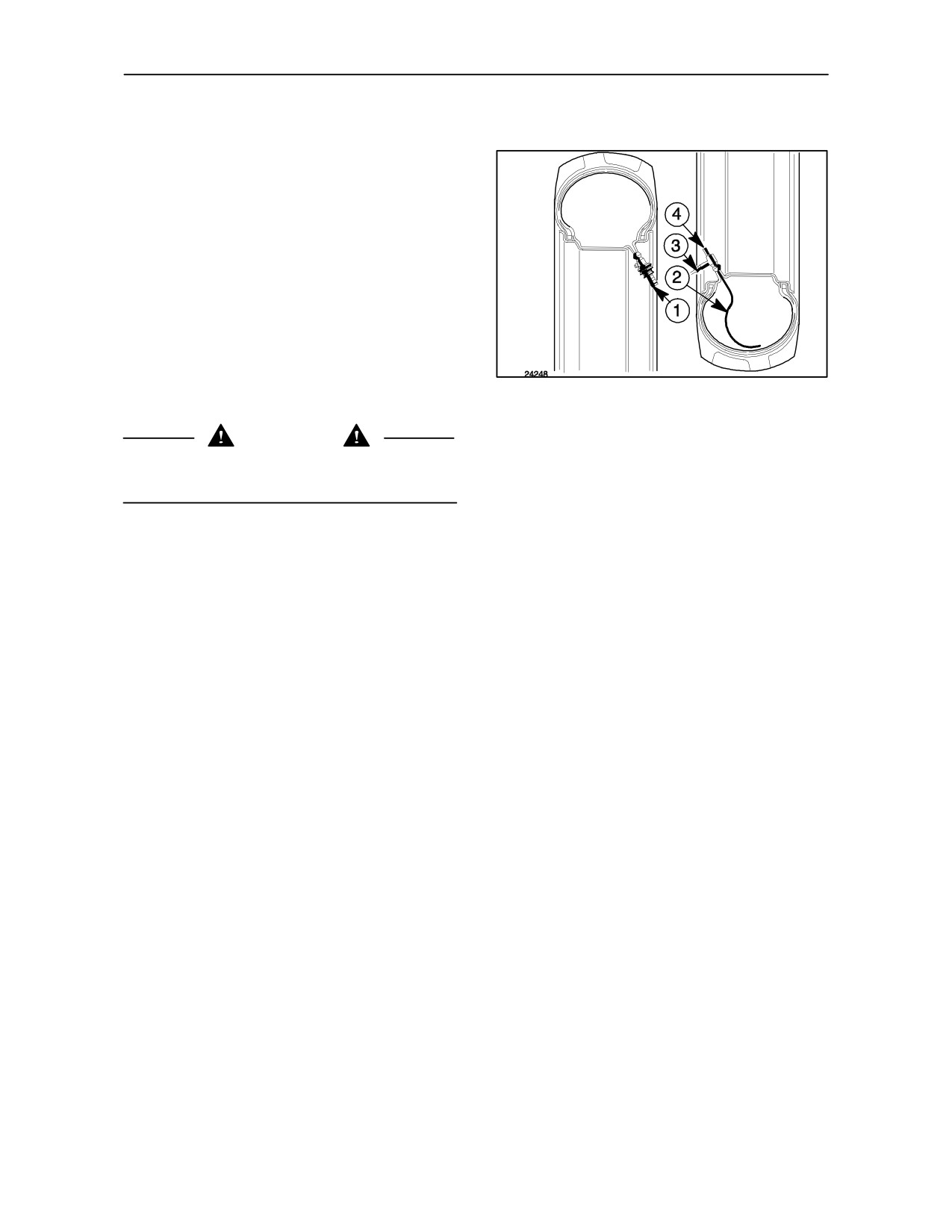
CONNECTORS FOR FILLING UP AND
DRAINING WATER -- Fig. 60
1. Connector for filling up water.
2. Water drainage tube.
3. Air line attachment.
4. Water drainage tube.
Water can be used to ballast the rear tyres if there is
60
no danger of freezing.
HOW TO DRAIN WATER FROM THE
CAUTION
TYRES:
Water pressure filled--up must never exceed 4 bar
(kg/cm2).
--
raise the wheel off the ground and move the tyre
valve to its lowest position;
--
unscrew the valve seal and drain the water;
HOW TO FILL--UP THE TYRES WITH
WATER:
--
screw connector NEW HOLLAND No. 291886
--
raise the wheel off the ground and move the tyre
onto the valve seat, tubes (2) and (4) will come
valve to its highest position;
into contact with the inner tube;
--
slacken the valve inner and wait for the tyre to
deflate;
--
fill--up pressurised air through attachment (3),
--
lower the wheel until the tyre is around 30% flat
the remaining water will escape through tubes
to prevent the weight of the water damaging the
(2) and (4);
inner tube;
--
screw connector NEW HOLLAND No. 291885
onto the valve seat and fit the water tube to
--
remove the connector and replace it with the
connector (1) remembering to disconnect it when
valve seal, then inflate the tyre to the specified
the tyre starts to swell in order to let air out;
pressure.
--
when water escapes from connector (1) the tyre
is 75% full.
If youwishtofill--uplesswater, orachievealower
weight, position the wheel so that the valve is
lower;
--
remove connector (1), tighten up the tyre valve
and inflate with air to the specified pressure.
3--51
SECTION 3 -- FIELD OPERATIONS
Front tyres 4WD
FILLING WITH WATER
Water (
1)
Tyres
kg (litres)
Ibs
The quantity of water required for each tyre is only
12.4R--20
120
265
approximate.
11.2--24
90
199
FILLING TYRES WITH ANTIFREEZE
12.4--24
115
254
SOLUTIONS
360/70R--24
100
220
360/70R--20
90
199
To prevent freezing water damaging the tyres, use a
11.2--28
100
220
solution of neutralised calcium chloride (in flakes)
instead of pure water.
13.6--24
120
265
380/70R--24
130
287
Prepare the solution by filling the water required into
320/70R--24
70
154
a container and adding the calcium chloride a little at
420/70R--24
166
366
a time, stirring continuously.
14.9--24
150
331
The quantities of water and chloride required to make
(1) The quantities of water for each tyre shown in the
sufficient antifreeze solution to fill each tyre to 75%
table may differ depending on the tyre manufacturer.
are shown in the tables on the next page.
Rear tyres 4WD
Water (
1)
Tyres
kg (litres)
Ibs
14.9--30
205
452
12.4--36
150
331
13.6--36
180
397
DANGER
16.9--30
250
551
Always add the calcium chloride flakes to the water.
Pouring water into chloride can be dangerous.
420/70R--30
200
441
480/70R--30
255
562
18.4--30
320
705
CAUTION
13.6--38
190
419
You are advised to contact your tractor tyre
16.9--34
280
617
manufacturer’s specialist to ensure that you fill the
tyres correctly.
480/70R--34
285
628
18.4--34
360
794
(1) The quantities of water for each tyre shown in the
table may differ depending on the tyre manufacturer.
3--52
SECTION 3 -- FIELD OPERATIONS
FILLING FRONT TYRES WITH ANTIFREEZE SOLUTION, FOUR--WHEEL DRIVE MODELS
The figures given in the table below are for information only as they may vary depending on the type of tyres
used.
You are therefore advised to contact your local tyre specialist.
Minimum temperatures
--5oC (23oF)
--10oC (14oF)
--15oC (5oF)
--20oC (--4oF)
--25oC (--13oF)
TYRE
Water
Water
Water
Water
Water
Calcium
Calcium
Calcium
Calcium
Calcium
DIMENSIONS
kg
kg
kg
kg
kg
chloride
chloride
chloride
chloride
chloride
(litres)
(litres)
(litres)
(litres)
(litres)
kg (lbs)
kg (lbs)
kg (lbs)
kg (lbs)
kg (lbs)
(lbs)
(lbs)
(lbs)
(lbs)
(lbs)
82
9
78
16
76
21
75
26
73
29
12.4R--20
(181)
(20)
(172)
(35)
(168)
(46)
(165)
(57)
(161)
(64)
86
10
83
17
87
22
79
27
77
31
11.2--24
(190)
(22)
(183)
(37)
(192)
(48)
(174)
(59)
(170)
(68)
110
12
106
22
104
28
101
34
100
39
12.4--24
(243)
(27)
(234)
(48)
(230)
(62)
(223)
(75)
(221)
(86)
67
8
64
13
63
18
61
21
60
24
320/70R--20
(148)
(18)
(141)
(28)
(139)
(39)
(134)
(46)
(132)
(53)
96
11
92
19
90
25
88
30
86
34
360/70R--24
(212)
(24)
(203)
(42)
(199)
(55)
(194)
(66)
(190)
(75)
86
10
82
17
81
22
79
27
77
31
360/70R--20
(190)
(22)
(181)
(38)
(179)
(48)
(174)
(59)
(170)
(68)
96
11
92
19
90
25
88
30
86
34
11.2--28
(213)
(24)
(203)
(42)
(199)
(55)
(194)
(66)
(190)
(75)
115
13
110
23
108
30
106
41
103
41
13.6--24
(254)
(29)
(243)
(51)
(238)
(66)
(234)
(90)
(227)
(90)
125
14
120
25
117
32
114
39
112
44
380/70R--24
(276)
(31)
(265)
(55)
(258)
(70)
(252)
(86)
(247)
(97)
159
18
152
31
149
41
146
49
142
56
420/70R--24
(352)
(40)
(335)
(68)
(329)
(90)
(322)
(108)
(313)
(123)
144
16
138
28
135
37
132
45
129
51
14.9--24
(318)
(35)
(304)
(62)
(298)
(81)
(291)
(99)
(285)
(112)
3--53
SECTION 3 -- FIELD OPERATIONS
FILLING REAR TYRES WITH ANTIFREEZE SOLUTION, TWO AND FOUR--WHEEL DRIVE
MODELS
The figures given in the table below are for information only as they may vary depending on the type of tyres
used.
You are therefore advised to contact your local tyre specialist.
Minimum temperatures
--5oC (23oF)
--10oC (14oF)
--15oC (5oF)
--20oC (--4oF)
--25oC (--13oF)
TYRE
DIMENSIONS
Water
Calcium
Water
Water
Water
Water
Calcium
Calcium
Calcium
Calcium
kg
chloride
kg
kg
kg
kg
chloride
chloride
chloride
chloride
(litres)
kg
(litres)
(litres)
(litres)
(litres)
kg (lbs)
kg (lbs)
kg (lbs)
kg (lbs)
(lbs)
(lbs)
(lbs)
(lbs)
(lbs)
(lbs)
173
20
164
34
162
45
158
54
155
61
14.9--28
(381)
(44)
(362)
(75)
(357)
(99)
(348)
(119)
(342)
(135)
197
23
189
39
185
52
180
62
176
70
14.9--30
(434)
(51)
(417)
(86)
(408)
(115)
(397)
(137)
(388)
(154)
144
16
138
28
135
37
132
45
129
51
12.4--36
(318)
(35)
(304)
(62)
(298)
(82)
(291)
(99)
(284)
(112)
173
20
166
34
162
45
158
54
155
61
13.6--36
(381)
(44)
(366)
(75)
(357)
(99)
(348)
(119)
(342)
(135)
240
28
230
48
225
63
220
75
215
85
16.9--30
(529)
(62)
(507)
(106)
(496)
(139)
(485)
(165)
(474)
(187)
192
22
184
38
180
50
176
60
172
68
420/70R--30
(423)
(49)
(406)
(84)
(397)
(110)
(388)
(132)
(379)
(150)
245
28
235
48
162
48
230
77
224
87
480/70R--30
(540)
(62)
(518)
(106)
(357)
(230)
(507)
(170)
(494)
(192)
307
35
294
61
288
80
282
96
275
109
18.4--30
(677)
(77)
(648)
(135)
(635)
(176)
(622)
(212)
(606)
(240)
182
21
175
36
171
48
167
57
163
65
13.6--38
(401)
(46)
(386)
(79)
(377)
(106)
(368)
(126)
(359)
(143)
269
31
258
53
252
70
246
84
241
95
16.9--34
(593)
(68)
(569)
(117)
(556)
(154)
(542)
(185)
(531)
(209)
274
31
262
54
257
71
251
86
245
97
480/70R--34
(604)
(68)
(578)
(119)
(567)
(157)
(553)
(190)
(540)
(214)
345
39
331
68
324
90
316
108
309
122
18.4--34
(761)
(86)
(730)
(150)
(714)
(198)
(697)
(238)
(681)
(269)
3--54
SECTION 3 -- FIELD OPERATIONS
MAXIMUM PERMITTED WEIGHT
Correct static weight distribution guarantees
Working with the tractor fitted with excessive ballast
maximum tractor efficiency and productivity, and
can cause:
extends the service life of tractor components.
--
reduction in available power to operate the
implement connected and reduced productivity
as a consequence;
--
increased fuel consumption;
CAUTION
--
excessive compacting of the soil;
The total weight of the tractor, including all types of
ballast and the weight of the implements carried,
--
damaging overload of the transmission
must not exceed the limits given in the table below.
components with a consequent increase in
running costs.
When using the tractor in the field, it is extremely
important to have the maximum power available for
using implements; therefore avoid losing power
through excessive ballast.
Maximum permissible weights on axles without limitations
Maximum permissible axle weight
Model
Front axle
Front axle
Rear axle
2WD kg (lbs)
4WD kg (lbs)
kg (lbs)
TD 60D
2400* (5291)
2650* (5842)
4000
(8819)
TD 70D
2400* (5291)
2650* (5842)
4000
(8819)
TD 80D
2500* (5512)
2800* (6173)
4150
(9149)
TD 90D
2500* (5512)
2900* (6393)
4150
(9149)
TD 95D
2600* (5732)
3000* (6614)
4250
(9370)
(*)
at max speed and max track.
The admissible static rear axle weights given are for tractors with ballast including equipment carried raised from
the ground.
Maximum permissible weights on axles with limitations
Maximum permissible axle weight
Model
Front axle
Front axle
Rear axle
2WD kg (lbs)
4WD kg (lbs)
kg (lbs)
TD 60D
3000* (6614)
3500** (7716)
3500
(7716)
TD 70D
3000* (6614)
3500** (7716)
3500
(7716)
TD 80D
3000* (6614)
4000** (8819)
4000
(8819)
TD 90D
3000* (6614)
4000** (8819)
4000
(8819)
TD 95D
3000* (6614)
4000** (8819)
4000
(8819)
(*)
for low speed (10 km/h) and at min track.
(**)
for low speed (10 km/h) and at medium track; (use with front loader, not permitted on road).
3--55
SECTION 3 -- FIELD OPERATIONS
WARNING
WARNING
Do not use ballast systems other than those
With mounted implements fitted to the rear of the
indicated.
tractor, it is a good idea to fit a minimum 20% extra
Do not ballast the tractor unnecessarily; not only is
weight on the front axle.
it superfluous, it can also damage the tractor.
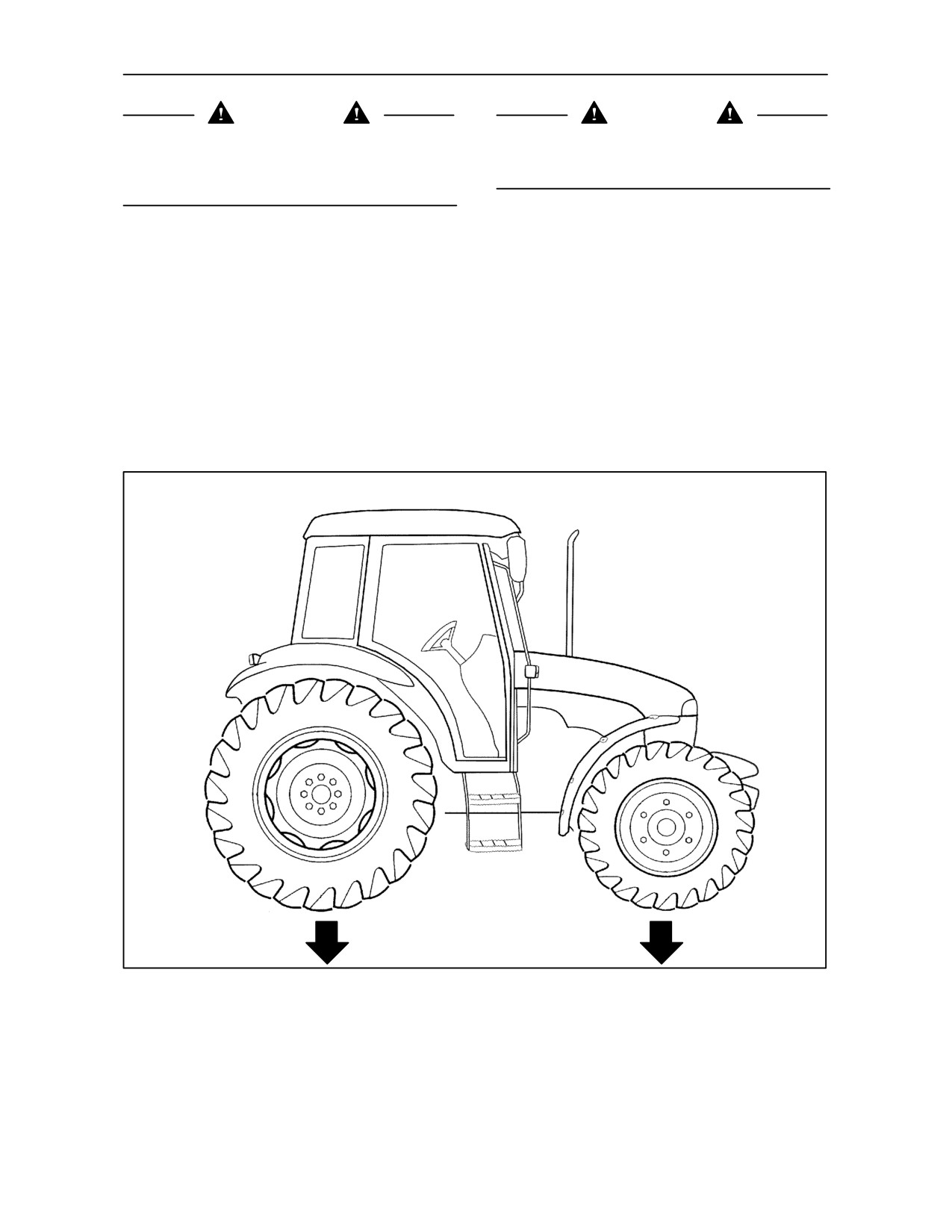
STATIC WEIGHT DISTRIBUTION ON THE TRACTOR -- Fig. 61
Add or remove ballast from the tractor once it is fully
The weight distribution percentages given for the
equipped, until a balanced static weight distribution
four--wheel drive models are indicative only and
is achieved for the implement actually used, taking
relate to the total weight of the fully equipped tractor
care not to exceed the maximum operating weights
complete with ballast.
given on page 3--55.
FOUR WHEEL DRIVE MODELS
TRE0031A
61
REAR AXLE
FRONT AXLE
60%
40%
3--56