New Holland TD 60D, TD 70D, TD 80D, TD 90D, TD 95D Tractor. OPERATOR’S MANUAL - page 1
TD 60D
TD 70D
TD 80D
TD 90D
TD 95D
OPERATOR’S MANUAL
SECTION SUMMARY
1 -- General Information and Safety
2 -- Controls, Instruments and Operation
3 -- Field Operation
4 -- Lubrication and Maintenance
5 -- Fault Finding
6 -- Vehicle Storage
7 -- Accessories
8 -- Specifications
9 -- First 50--Hour Service Forms
10 -- Index
CONTENTS
Title
Page
Section 1 -- General Information and Safety
To the owner
1--1
Tractor identification
1--2
Ecology and the environment
1--5
Safety precautions
1--6
Safety decals
1--12
International symbols
1--15
Section 2 -- Controls, Instruments and Operation
Safety covers and guards
2--2
Controls and instruments
2--4
Instrument panel
2--5
Instrument console controls
2--11
Right--hand side operating controls
2--12
Left--hand side operating controls
2--13
Cab controls
2--15
Seats
2--16
Cab
2--19
Cab air conditioning system
2--27
Transmission with range gear -- 30 km/h (19 mph)
2--31
Transmission with range gear and shuttle-- 30 km/h (19 mph)
2--33
Transmission with creeper and shuttle-- 30 km/h (19 mph)
2--36
Mechanically controlled four wheel drive
2--39
Mechanically controlled differential lock
2--40
Towing the tractor
2--42
Loading the tractor onto a transporter
2--42
Checks before using the tractor
2--43
Section 3 -- Field Operation
Starting with thermostart the engine
3--3
Power take--off
3--5
Hydraulic lift
3--18
Three--point linkage Cat. II
3--23
Remote control valves
3--30
Wheel track adjustment
3--32
Tyres
3--39
Tyre combinations
3--43
Ballasting
3--50
Static weight distribution
3--50
Section 4 -- Lubrication and Maintenance
Access for inspection and maintenance
4--4
Lubrication and maintenance table
4--5
Flexible maintenance
4--7
When the warning light is on
4--9
10--hour / daily service
4--10
50--hour service
4--16
300--hour service
4--19
600--hour service
4--24
900--hour service
4--24
1200--hour service
4--24
1200--hour or every 2 years service
4--27
General maintenance
4--31
Electrical system
4--33
Recommendations for bodywork maintenance
4--40
Lubricant capacities and specifications
4--41
Section 5 -- Fault Finding
Introduction
5--1
Engine
5--2
Electrical system
5--5
Hydraulic system
5--6
Three-point linkage
5--7
Brakes
5--8
Cab
5--8
Section 6 -- Vehicle Storage
6--1
Section 7 -- Accessories
Beacon lamp
7--2
Drawbars and towing attachments
7--3
Hydralic trailer brake
7--9
Section 8 -- Specifications
General Dimensions
8--2
Weights
8--4
Engine specifications
8--5
Timing
8--6
Fuel system
8--6
Lubrication
8--7
Cooling system
8--7
Transmission
8--7
Power take--off
8--8
Hydraulic system
8--8
Three-point linkage
8--9
Front axle
8--9
Steering
8--10
4WD front axle
8--10
Brakes
8--11
Bodywork and driving position
8--11
Towing devices
8--11
Electrical system
8--12
Section 9 -- First 50--hour Service Forms
9--1
Section 10 -- Index
10--1
SECTION 1
GENERAL INFORMATION AND SAFETY
TO THE OWNER
SAFETY
GENERAL
Pages 1--6 to 1--11 inclusive list the precautions to
be observed to ensure your safety and the safety of
This Manual has been prepared to assist you in the
others. Read the safety precautions and follow the
correct procedure for running--in, driving and
advice offered before operating the tractor.
operating and for the maintenance of your new
tractor. Read this Manual carefully. Your tractor is
FIRST 50 HOUR SERVICE
intended for use in normal and customary
agricultural applications.
In Section 9, at the back of this Manual, you will find
the 50--hour service reports.
If at any time you require advice concerning your
tractor, do not hesitate to contact your New Holland
After you have operated the tractor for 50 hours, take
dealer. He has factory trained personnel, genuine
your tractor, together with this Manual, to your dealer.
manufacturers’ parts and the necessary equipment
He will then perform the factory recommended 50--
to carry out all your service requirements.
hour service and complete the service report sheets
(pages 9--1 and 9--3). The first sheet (page 9--1) is the
Your tractor has been designed and built to give
dealer’s copy and should be removed by the dealer
maximum performance, economy and ease of
after the service has been carried out. The second
operation under a wide variety of operating
sheet
(page
9--3) is your copy of the service
conditions. Prior to delivery, the tractor was carefully
performed. Ensure that you and the dealer sign
inspected, both at the factory and by your dealer to
both copies.
ensure that it reaches you in optimum condition. To
maintain this condition and ensure trouble--free
operation, it is important that the routine services, as
specified in Section 4 of this Manual, are carried out
at the recommended intervals.
SERVICE PARTS
It should be pointed out that genuine parts have been
examined and approved by the Company. The
installation and/or use of
‘non-genuine’ products
could have negative effects upon the design
characteristics of your tractor and thereby affect it’s
safety. The Company is not liable for any damage
caused by the use of
‘non--genuine’ parts and
CLEANING THE TRACTOR
accessories. Only genuine replacement parts should
be used. The use of non-genuine parts may
Your tractor is a state-of-the-art machine with
invalidate legal approvals associated with this
sophisticated controls. This should be borne in mind
product.
when cleaning the tractor, particularly if using a high
pressure washer. Even though every precaution has
been taken to safeguard electrical components and
It is prohibited to carry out any modifications to the
connections, the pressure generated by some of
tractor unless specifically authorised, in writing, by
these machines is such that complete protection
the After Sales Service department of the Company.
against water ingress cannot be guaranteed.
WARRANTY
When using a high pressure washer, do not stand too
close to the tractor and avoid directing the jet at
Your tractor is warranted according to legal rights in
electronic components, electrical connections,
your country and the contractual agreement with the
breathers, seals, filler caps, etc. Never direct a cold
selling dealer. No warranty shall, however, apply if
water jet at a hot engine or exhaust.
the tractor has not been used, adjusted and
maintained according to the instructions given in the
Operator’s Manual.
1--1
SECTION 1 -- GENERAL INFORMATION AND SAFETY
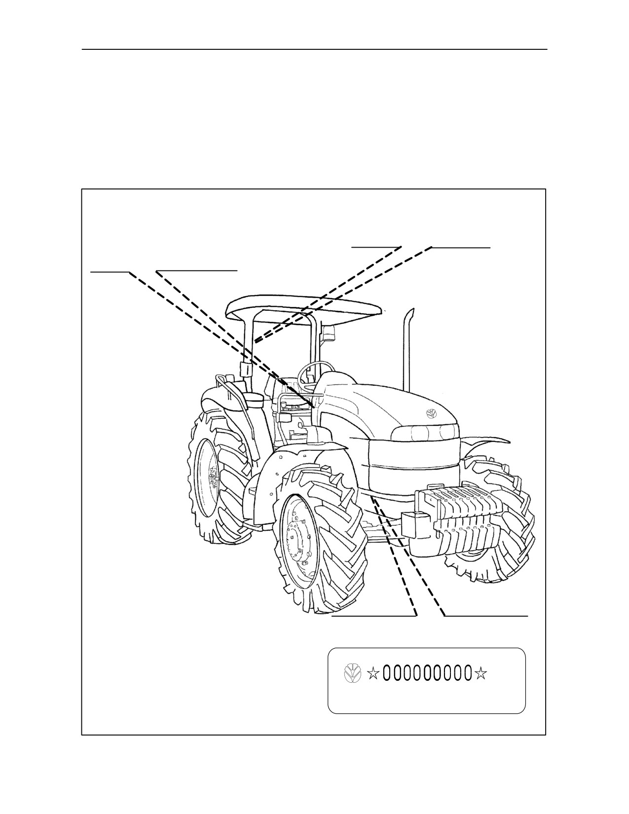
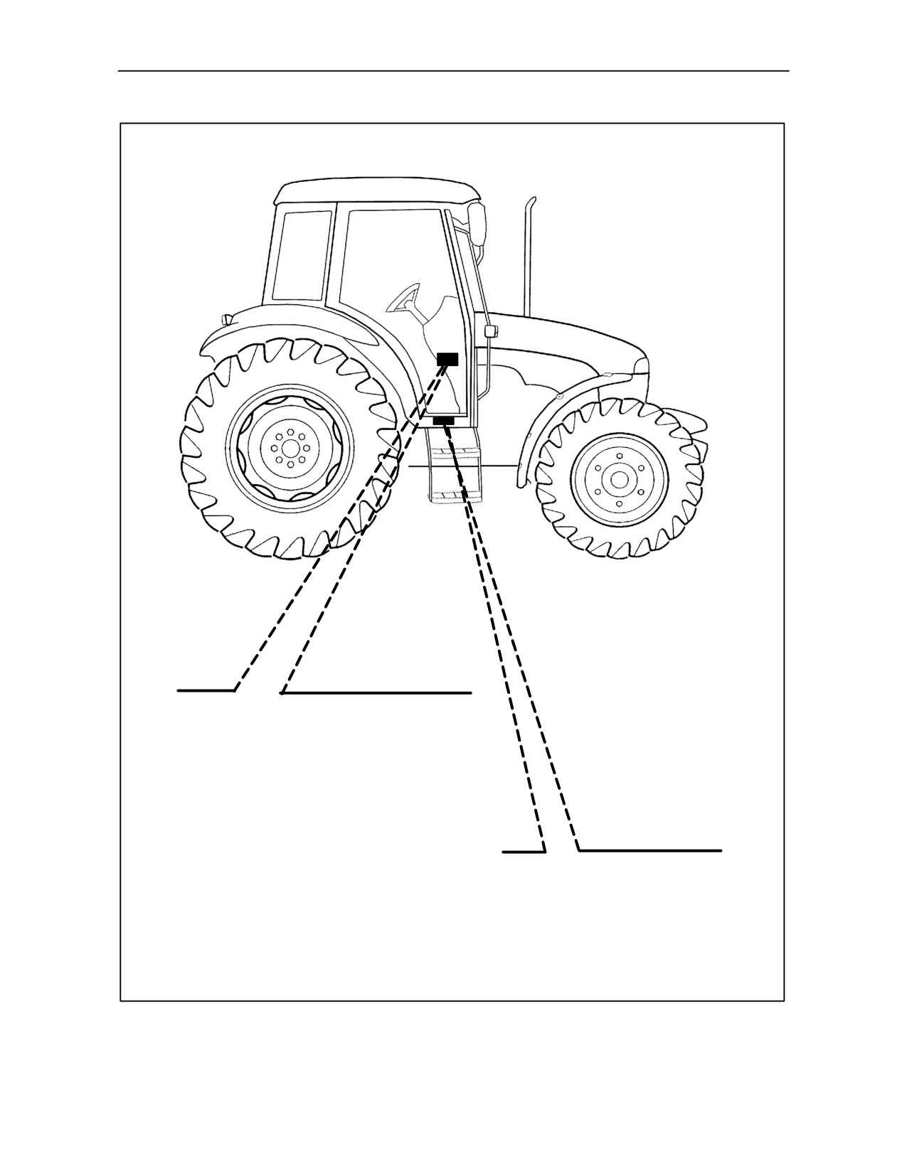
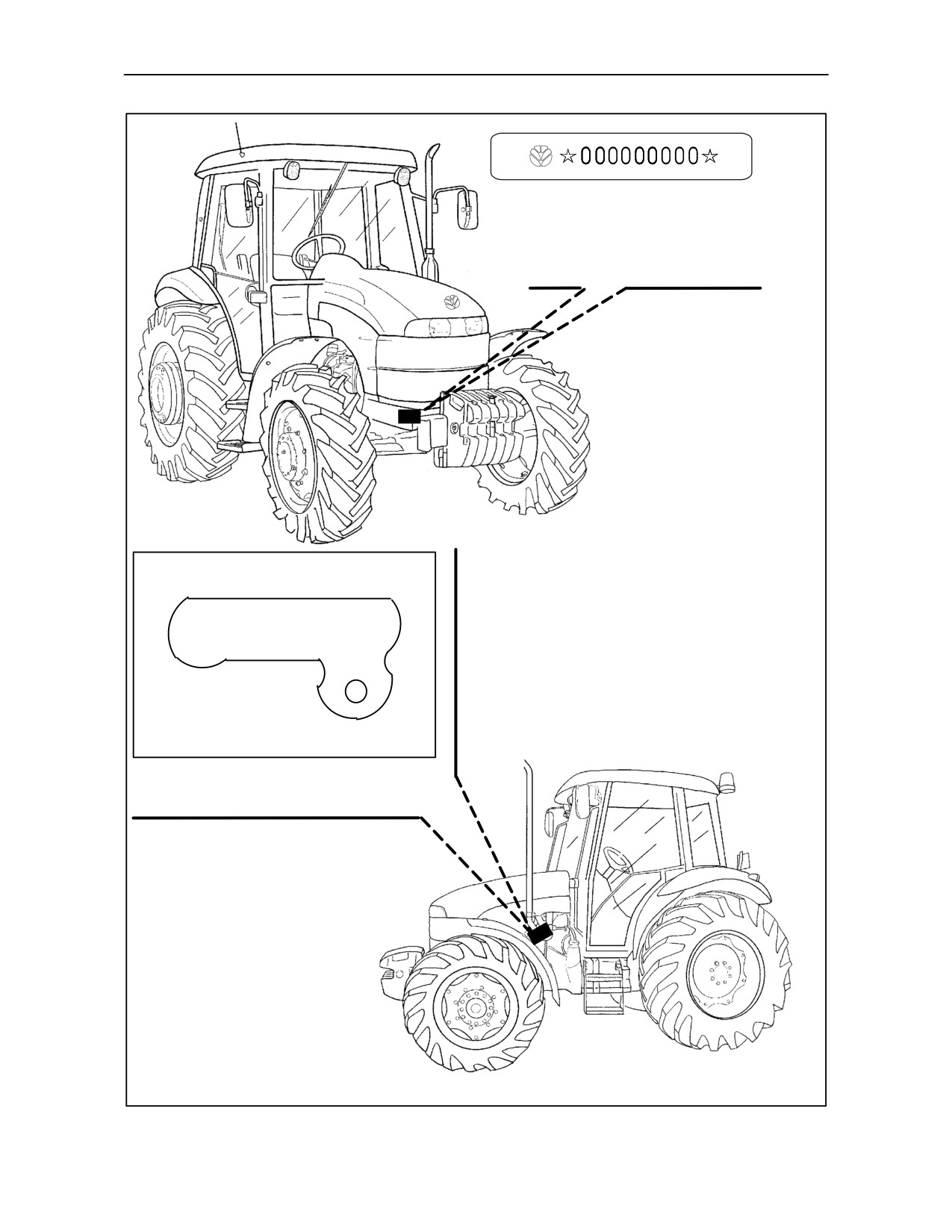
TRACTOR IDENTIFICATION
Serial numbers identify the tractor and its main components. The identification data must be supplied by the
dealer for requests for spare parts or service operations. Identification data is of fundamental importance in the
event of theft of the tractor. The location of the various identification data is shown below.
Frame identification data plate.
Frame and engine type
identification data plate.
Tractor frame number identification data
plate (stamped on the axle support )
TRE0080A
1--2
SECTION 1 -- GENERAL INFORMATION AND SAFETY
Frame and engine type identification data
plate (inside the cab).
Cab identification data plate.
TRE0061A
1--3
SECTION 1 -- GENERAL INFORMATION AND SAFETY
Tractor frame number
identification data plate
(stamped on the axle support)
Engine identification data plate
(stamped on engine body).
TRE0081A
1--4
SECTION 1 -- GENERAL INFORMATION AND SAFETY
ECOLOGY AND THE ENVIRONMENT
Soil, air and water are vital factors of agriculture and
3.
Modern oils contain additives. Do not burn
life in general. Where legislation does not yet rule the
contaminated fuels and/or waste oils in ordinary
treatment of some of the substances which are
heating systems.
required by advanced technology, common sense
should govern the use and disposal of products of a
4.
Avoid spillage when draining off used engine
chemical and petrochemical nature.
coolant mixtures, engine, gearbox and hydraulic
oils, brake fluids, etc. Do not mix drained brake
fluids or fuels with lubricants. Store them safely
until they can be disposed of in a proper way to
The following are recommendations which may be of
comply with local legislation and available
assistance:
resources.
• Become acquainted with and ensure that you
5.
Modern coolant mixtures, i.e. antifreeze and
understand the relative legislation applicable to
other additives, should be replaced every two
your country.
years. They should not be allowed to get into the
soil but should be collected and disposed of
• Where no legislation exists, obtain information
safely.
from suppliers of oils, filters, batteries, fuels,
antifreeze, cleaning agents, etc., with regard to
6.
Do not open the air-conditioning system yourself.
their effect on man and nature and how to safely
It contains gases which should not be released
store, use and dispose of these substances.
into the atmosphere. Your dealer or air
Agricultural consultants will, in many cases, be
conditioning specialist has a special extractor for
able to help you as well.
this purpose and will have to recharge the system
anyway.
7.
Repair any leaks or defects in the engine cooling
HELPFUL HINTS
or hydraulic system immediately.
1. Avoid filling tanks using unsuitable containers or
8.
Do not increase the pressure in a pressurised
inappropriate pressurised fuel delivery systems
circuit as this may lead to the components
which may cause considerable spillage.
exploding.
2. In general, avoid skin contact with all fuels, oils,
9.
Protect hoses during welding as penetrating
acids, solvents, etc. Most of them contain
weld splatter may burn a hole or weaken them,
substances which can be harmful to your health.
causing the loss of oils, coolant, etc.
1--5
SECTION 1 -- GENERAL INFORMATION AND SAFETY
SAFETY PRECAUTIONS
A careful operator is the best operator. Most accidents
THE TRACTOR
can be avoided by observing certain precautions. To
help prevent accidents, read and take the following
1.
Read the Operator’s Manual carefully before
precautions before driving, operating or servicing the
using the tractor. Lack of operating knowledge
tractor. Equipment should be operated only by those
can lead to accidents.
who are responsible and instructed to do so.
2.
Only allow properly trained and qualified persons
PRECAUTIONARY STATEMENTS
to operate the tractor.
Throughout this Manual you will see text, preceded
3.
To prevent falls, use the handrails and step plates
by the words NOTE, ATTENTION, IMPORTANT,
when getting on and off the tractor. Keep steps
CAUTION, WARNING or DANGER. Such text has
and platform clear of mud and debris.
the following significance:
4.
Replace all missing, illegible or damaged safety
MACHINE SAFETY
decals.
NOTE: This text stresses a correct operating
5.
Keep safety decals free of dirt or grime.
technique or procedure.
ATTENTION: This text warns the operator of potential
machine damage if a certain procedure is not followed.
IMPORTANT: This text informs the reader of
something that he needs to know to prevent minor
machine damage if a certain procedure is not
followed.
PERSONAL SAFETY
CAUTION
The word CAUTION is used where a safe
behavioural practice, according to operating and
maintenance instructions and common safety
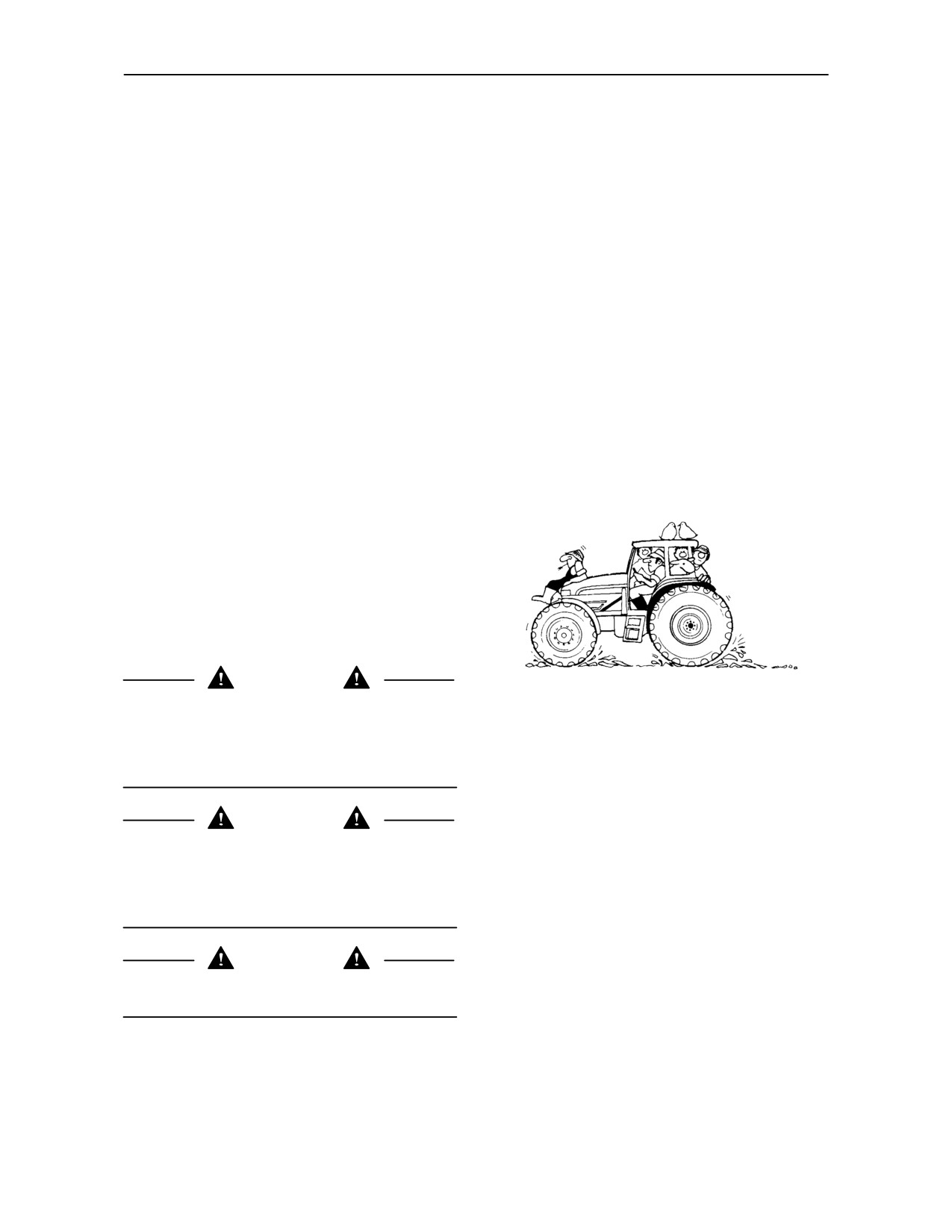
6.
Do not permit anyone but the operator to ride on
practices will protect the operator and others from
the tractor unless a passenger seat is fitted.
accident involvement.
There is no safe place for extra passengers
otherwise.
WARNING
7.
Keep children away from the tractor and farm
The word WARNING denotes a potential or hidden
machinery at all times.
hazard which could possibly cause serious injury. It
is used to warn operators and others to exercise due
8.
Do not modify or alter or permit anyone else to
care and attention to avoid a surprise accident with
modify or alter the tractor or any of its
machinery.
components or any tractor function without first
consulting your dealer.
DANGER
9.
Install all guards before starting the engine or
The word DANGER denotes a forbidden practice in
operating the tractor.
connection with a serious hazard.
Failure to follow the CAUTION, WARNING and
DANGER instructions may result in serious bodily
injury or even death.
1--6

SECTION 1 -- GENERAL INFORMATION AND SAFETY
DRIVING THE TRACTOR
1.
Always sit in the driver’s seat while starting or
driving the tractor.
2.
When driving on public roads, have
consideration for other road users. Pull in to the
side of the road occasionally to allow any
following traffic to pass. Do not exceed the legal
speed limit set in your country for agricultural
tractors.
3.
Use a rotating beacon when driving on public
roads to indicate that the vehicle is slow moving
and is a possible hazard.
7.
Keep the tractor in the same gear when going
downhill as would be used when going uphill. Do
not coast or freewheel down hills.
4.
Dip the tractor lights when meeting a vehicle at
night. Make sure the lights are adjusted to
8.
For safe operation any towed vehicle whose total
prevent blinding the driver of an oncoming
weight exceeds that of the towing tractor must be
vehicle.
equipped with a braking system that complies
with the legal requirements of that country.
5.
Reduce speed before turning or applying the
brakes. Brake both wheels simultaneously when
9.
Never apply the differential lock when turning.
making an emergency stop. Ensure that both
When engaged, the differential lock will prevent
brake pedals are locked together when travelling
the tractor from turning.
at road speeds or when on public roads to ensure
correct operation of trailer brakes, balanced
10. Always check overhead clearance, especially
operation of the tractor brakes and four wheel
when transporting the tractor. Watch where you
braking (4WD tractors only).
are going, especially at row ends, on roads and
around trees and low overhanging obstacles.
11. To avoid overturns, drive the tractor with care and
at speeds compatible with safety, especially
when operating over rough ground, when
crossing ditches or slopes and when turning
corners.
6. Use extreme caution and avoid hard application
of the tractor brakes when towing heavy loads at
road speeds.
12. Use extreme caution when operating on steep
slopes.
13. If the tractor becomes stuck or the tyres are
frozen to the ground, reverse the tractor out to
prevent overturning.
1--7

SECTION 1 -- GENERAL INFORMATION AND SAFETY
OPERATING THE TRACTOR
1. Apply the parking brake, place the P.T.O. control
in the ‘OFF’ position, the lift control lever in the
down position, the remote control valve levers in
the neutral position and the transmission levers
in neutral before starting the tractor.
2. Do not start the engine or operate controls (other
than externally located hydraulic lift or P.T.O.
switches, if fitted) while standing beside the
tractor. Always sit in the tractor seat when
starting the engine or operating the controls.
3. Do not bypass the transmission and P.T.O.
8.
Do not park the tractor on a steep incline.
neutral start switches. Consult your authorised
dealer if your neutral start controls malfunction.
9.
The cab is designed to provide the minimum
Use jump leads only in the recommended
noise level at the operator’s ears and meets or
manner. Improper use can result in a tractor
exceeds applicable standards in this respect.
runaway.
However, noise (sound pressure level) in the
workplace can exceed 85 dB(A) when working
between buildings or in confined spaces, with
cab windows open. Therefore, it is
recommended that operators wear suitable ear
protectors when operating in high noise level
conditions.
4. Avoid accidental contact with the gear shift levers
while the engine is running. Unexpected tractor
movement can result from such contact.
5. Do not get off the tractor while it is in motion.
6. If the power steering or engine ceases operating,
10. Do not run the tractor engine in an enclosed
stop the tractor immediately as the tractor will be
building without adequate ventilation. Exhaust
more difficult to control.
fumes are toxic and can cause death.
7. Before leaving the tractor, park the tractor on
11. Pull only from the pick-up hitch, swinging
level ground, apply the parking brake, lower
drawbar or the lower link drawbar in the lowered
attached implements to the ground, disengage
position. Use only a drawbar pin that locks in
the P.T.O. and stop the engine.
place. Pulling from the tractor rear axle or any
point above the axle may cause the tractor to
overturn.
1--8

SECTION 1 -- GENERAL INFORMATION AND SAFETY
12. Always select Position Control when attaching
OPERATING THE P.T.O.
equipment and when transporting equipment. Be
sure hydraulic couplers are properly mounted
1. When operating PTO- driven equipment, shut off
and will disconnect safely in case of accidental
the engine, switch off the PTO and wait until the
detachment of the implement.
PTO stops before getting off the tractor and
disconnecting the equipment.
13. If the front end of the tractor tends to rise when
heavy implements are attached to the
2.
Do not wear loose clothing when operating the
three--point hitch, install front end or front wheel
power take-off or especially when near rotating
weights. Do not operate the tractor with a light
equipment.
front end.
3.
When operating stationary PTO-driven
14. Engage the clutch slowly when driving out of a
equipment, always apply the tractor parking
ditch, gully or up a steep hillside. Disengage the
brake and block the rear wheels front and back.
clutch promptly if the front wheels rise off the
ground.
15. Ensure any attached equipment or accessories
are correctly installed, are approved for use with
the tractor, do not overload the tractor and are
operated and maintained in accordance with the
instructions issued by the equipment or
accessory manufacturer.
16. Remember that your tractor, if abused or
incorrectly used, can be dangerous and become
a hazard both to the operator and to bystanders.
Do not overload or operate with attached
equipment which is unsafe, not designed for the
particular task or is poorly maintained.
4.
To avoid injury, do not clean, adjust, unclog or
17. Do not leave equipment in the raised position
service PTO driven equipment when the tractor
when the vehicle is stopped or unattended.
engine is running. Ensure that the PTO is
switched off.
18. Do not drive equipment near open fires.
5.
Make sure the PTO guard is in position at all
times and always replace the PTO cap when the
19. Always wear a protective mask when working
PTO is not in use.
with toxic spray chemicals. Follow the directions
on the chemical container.
1--9

SECTION 1 -- GENERAL INFORMATION AND SAFETY
SERVICING THE TRACTOR
Unqualified persons should not remove or
attempt to adjust a pump, injector, nozzle or any
other part of the fuel injection or hydraulic
systems. Failure to follow these instructions can
result in serious injury.
• Do not use your hand to check for leaks. Use a
piece of cardboard or paper to search for leaks.
• Stop the engine and relieve pressure before
connecting or disconnecting lines.
1.
The cooling system operates under pressure
which is controlled by the expansion tank cap. It
is dangerous to remove the cap while the system
is hot. Always turn the cap slowly to the first stop
and allow the pressure to escape before
removing the cap entirely. Never remove the cap
from the top of the radiator unless the expansion
tank pressure cap has first been removed.
2.
Do not smoke while refuelling the tractor. Keep
any type of open flame away.
•
Tighten all connections before starting the
engine or pressurising lines.
3.
Keep the tractor and equipment, particularly
brakes and steering, maintained in a reliable and
•
If fluid is injected into the skin obtain medical
satisfactory condition to ensure your safety and
attention immediately or gangrene may result.
comply with legal requirements.
8.
Do not modify or alter or permit anyone else to
4.
To prevent fire or explosion, keep open flames
modify or alter the tractor or any of its
away from battery or cold weather starting aids.
components or any tractor function without first
To prevent sparks which could cause explosion,
consulting an authorised dealer.
use jumper cables according to instructions.
9.
Continuous long term contact with used engine
5.
Do not attempt to service the air conditioning
oil may cause skin cancer. Avoid prolonged
system. It is possible to be severely frost bitten or
contact with used engine oil. Wash skin promptly
injured by escaping refrigerant. Special
with soap and water.
equipment and instruments are required to
service the air conditioning system. See your
10. Keep equipment clean and properly maintained.
authorised dealer for service.
11. Dispose of all drained fluids and removed filters
6.
Stop the engine before performing any service
properly.
on the tractor.
12. Tractor wheels are very heavy. Handle with care
7.
Hydraulic fluid and fuel oil in the injection system
and ensure, when stored, that they can not topple
operate under high pressure. Escaping hydraulic
and cause injury.
fluid or fuel oil under pressure can penetrate the
skin causing serious injury.
1--10
SECTION 1 -- GENERAL INFORMATION AND SAFETY
DIESEL FUEL
7. Always tighten the fuel tank cap securely.
1. Under no circumstances should gasoline,
8. If the original fuel tank cap is lost, replace it with
alcohol or blended fuels be added to diesel fuel.
an approved cap. A non--approved cap may not
These combinations can create an increased fire
be safe.
or explosive hazard. In a closed container such
as a fuel tank these blends are more explosive
9. Never use fuel for cleaning purposes.
than pure gasoline. Do not use these blends.
10. Arrange fuel purchases so that summer grade
2. Never remove the fuel cap or refuel with the
fuels are not held over and used in the winter.
engine running or hot.
SAFETY CAB
Your tractor is equipped with a safety cab which must
be maintained in a serviceable condition. Be careful
when driving through doorways or working in
confined spaces with low headroom.
1. Do not modify, drill, weld or alter the safety cab in
any way. Doing so could render you liable to legal
prosecution in some countries.
2. Never attempt to straighten or weld any part of
the main frame or retaining brackets which have
3.
Do not smoke while refuelling the tractor or when
suffered damage. By doing so you may weaken
standing near fuel. Keep any type of open flame
the structure and endanger your safety.
away.
3. Do not secure any parts on the main frame or
4.
Maintain control of the fuel filler pipe nozzle when
attach your safety cab with other than the special
filling the tank.
high tensile bolts and nuts specified.
5.
Do not fill the fuel tank to capacity. Fill only to the
4. Never attach chains or ropes to the cab or main
bottom of the filler neck to allow room for
frame for pulling purposes.
expansion.
5. Never take unnecessary risks even though your
6.
Wipe up spilled fuel immediately.
safety cab affords you the maximum protection
possible.
WHENEVER YOU SEE THIS SYMBOL
IT MEANS: ATTENTION!
BECOME ALERT! YOUR SAFETY IS INVOLVED!
1--11
SECTION 1 -- GENERAL INFORMATION AND SAFETY
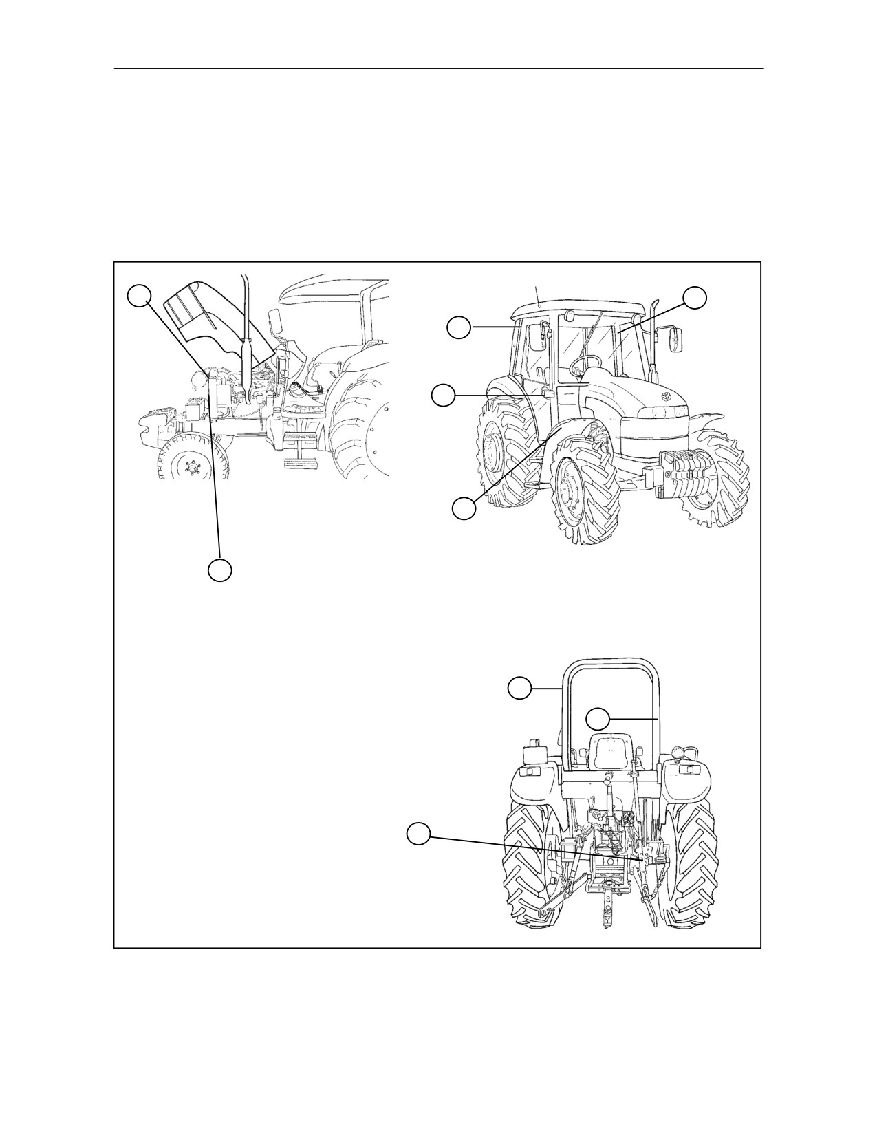
SAFETY DECALS
The decals reproduced on the following pages were installed on your tractor in the positions indicated in the drawings
below. They are intended for your safety and for those working with you. Please take this Manual and walk around
your tractor, noting the location of the decals and their significance. Review the decals and operating instructions
detailed in this Manual with the machine operators. Keep the decals clean and legible. If they become damaged or
illegible, obtain replacements from your authorised dealer.
5
1
3
7
TRE0004A
6
TRE0023A
4
1
3
2
TRE0062A
1--12
SECTION 1 -- GENERAL INFORMATION AND SAFETY
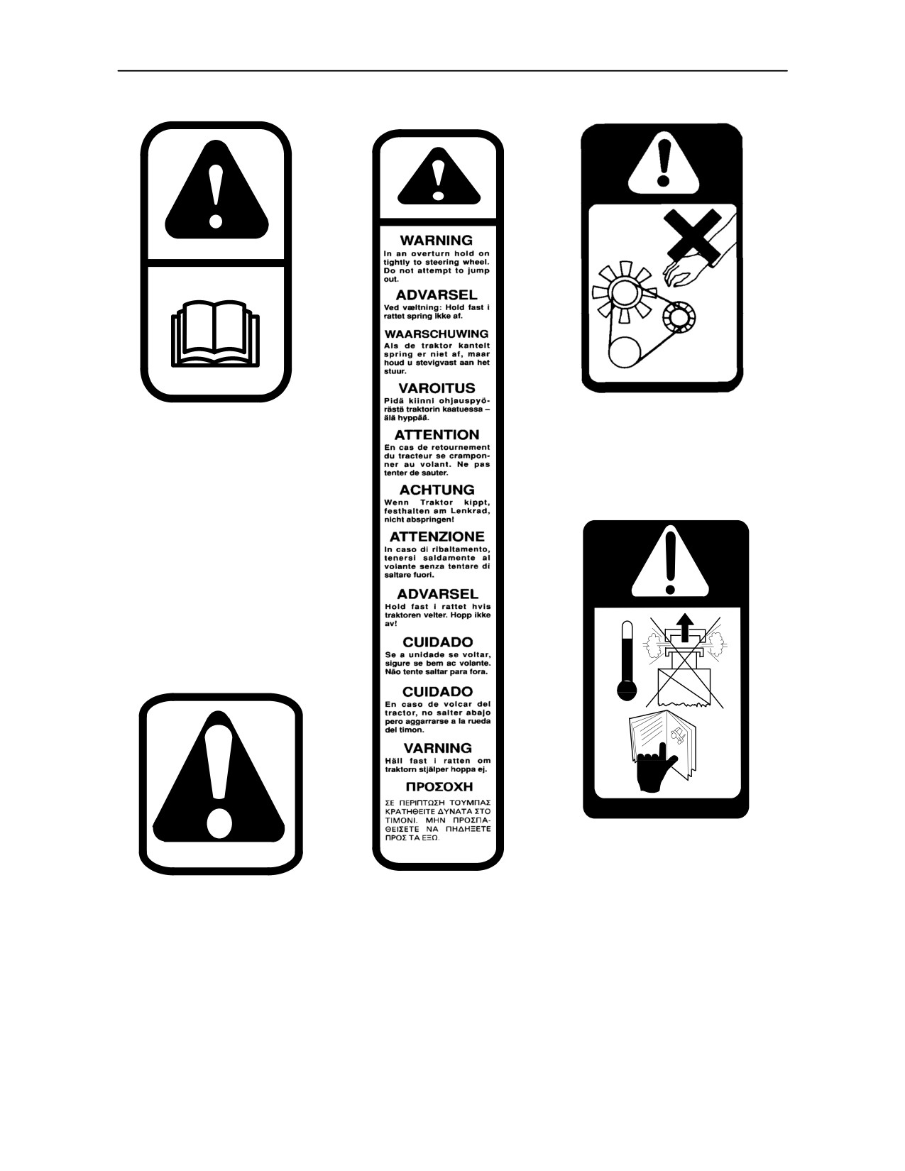
4. Location: Left and right--
1. Location: On the
hand sides of the radiator.
left--hand upright of
To avoid serious injury, keep
ROPS and inside the
hands and clothing away
cab and also on the
from the rotating fan, belts
filter drier under the
and any other rotating parts.
bonnet.
Non--compliance with
the instructions provided
in this manual can lead to
serious injury to the ope-
rator or bystanders.
Read the instructions on
pages
1--6
to
1--11
inclusive.
5.
Location: Left and
right--hand side of the ra-
diator.
3. Location: On the
WARNING:
Pressurised
right--hand upright of
cooling system. Allow to cool
2. Location: On the
ROPS and inside the
then remove cap carefully.
right--hand lift rod
cab.
Use a cloth to slowly unscrew
GENERAL WARNING:
If
the tractor should
the cap and release the
Observe and respect the
overturn,
hold
the
pressure before completely
indications on the safety
steering wheel tightly. Do
removing the cap.
decals when this symbol is
not attempt to jump out of
present.
the cab.
1--13

SECTION 1 -- GENERAL INFORMATION AND SAFETY
7. Location: Front of transmission console (less cab tractors only)
-- all countries.
6. Location: Tool box lid.
Do not grasp the transmission levers when mounting the tractor. Use only
the hand holds provided.
7. Location: Front of transmission console (tractors with cab only)
-- all countries.
Do not grasp the transmission levers when mounting the tractor. Use only
the hand holds provided.
1--14
SECTION 1 -- GENERAL INFORMATION AND SAFETY
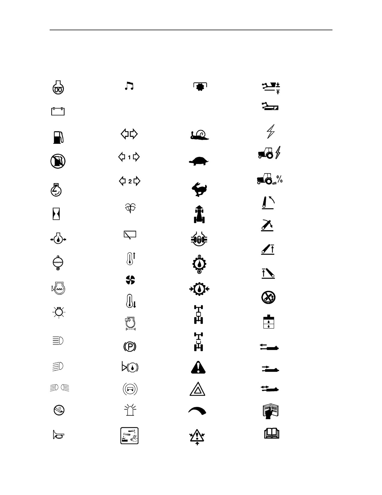
INTERNATIONAL SYMBOLS
As a guide to the operation of your tractor, various universal symbols have been utilised on the instruments,
controls, switches, and fuse box. The symbols are shown below with an indication of their meaning.
Thermostart
Radio
P.T.O.
Position
starting aid
Control
Keep alive
Draft
Alternator
memory
N
Transmission
Control
KAM
charge
in neutral
Accessory
Turn signals
Creeper
socket
Fuel level
gears
Implement
Turn signals
Automatic
Slow or
socket
--one trailer
fuel shut-off
low setting
Turn signals
% slippage
--two trailers
Engine speed
Fast or high
(rev/min x 100)
setting
Front wind-
Hitch raise
screen
(rear)
Ground
Hours recorded
wash/wipe
speed
Hitch lower
Rear
(rear)
Engine oil
windscreen
Differential
pressure
wash/wipe
lock
Hitch height
Heater
limit (rear)
Engine coolant
temperature
Rear axle oil
temperature
control
temperature
Hitch height
limit (front)
Heater fan
Coolant
Transmission
level
oil pressure
Hitch dis-
abled
Air conditioner
FWD
Tractor lights
Hydraulic and
engaged
Air filter
transmission
blocked
filters
Headlamp
FWD
main beam
Parking
disengaged
Remote
brake
valve extend
Headlamp
Brake fluid
Remote
Warning!
dipped beam
level
valve retract
Trailer
Hazard
Remote
Work lamps
brake
warning lights
valve float
Malfunction!
Stop
Roof
Variable
See Operator’s
lamps
beacon
control
Manual
Warning!
Malfunction!
Corrosive
Pressurised!
(alternative
Horn
substance
Open carefully
symbol)
1--15
SECTION 1 -- GENERAL INFORMATION AND SAFETY
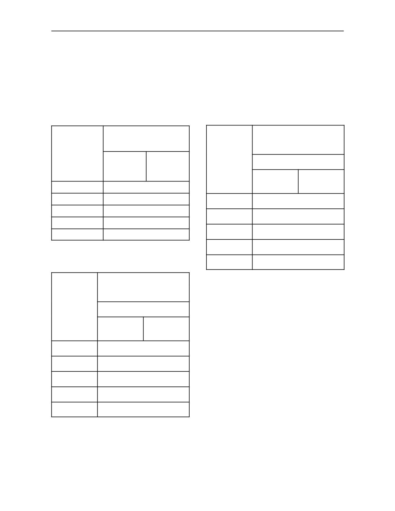
TRACTOR NOISE LEVEL INFORMATION SHEET
In compliance with DPR no. 212 enclosure 8 section II incorporating directive 77/311/EEC, the noise levels
for tractors fitted with tyres covered by the Use and Maintenance Manual are as specified below.
TRACTORS WITH ROLL BARS 2/4WD
TRACTORS WITH CABS 2/4WD
Maximum noise level at
Maximum noise level at
steering wheel
steering wheel with cab doors
dB (A)
and windows open
Model
30 km/h
40 km/h
Model
dB (A)
(19 mph)
(25 mph)
30 km/h
40 km/h
TD60D
85
(19 mph)
(25 mph)
TD70D
85
TD60D
83
TD80D
86
TD70D
80
TD90D
85
TD80D
82
TD95D
84
TD90D
83
TD95D
84
TRACTORS WITH CABS 2/4WD
Maximum noise level at
steering wheel with cab doors
and windows closed
WARNING -- If the noise level during continuous use
reaches or exceeds 85 dB (A), the user must adopt
Model
suitable precautions.
dB (A)
30 km/h
40 km/h
(19 mph)
(25 mph)
TD60D
80
TD70D
80
TD80D
80
TD90D
80
TD95D
80
1--16
SECTION 2
CONTROLS, INSTRUMENTS AND OPERATION
INTRODUCTION
This Operator’s Manual has been produced to
All the data provided in this Manual is subject to
provide the user with practical information,
product modifications. Weights and measures are to
documents and instructions about the correct
be considered approximate figures and the
procedure for running in, driving, operating and
illustrations do not necessarily show tractors with
maintaining the new tractor.
standard fittings.
For precise information on specific tractor models
and versions, please contact your authorised dealer.
The Manual is subdivided into 10 sections. The main
index is at the end of the Manual (Section 10).
The Company is engaged in a continuous process of
product development and improvement and
therefore reserves the right to change the
Read and refer to this Manual carefully, and always
keep it in a convenient place so that you can refer to
specifications, components and prices of the product
itself at any time, without prior notice.
it whenever necessary.
In this Manual, the ”left--hand”and ”right--hand”parts
If youshouldat anytimeneedinformation andadvice
of the tractor are as seen from the driver’s seat,
about using your tractor, please contact your
facing forward.
authorised dealer.
The dealer can provide skilled personnel, genuine
The necessary precautions to guarantee the
personal safety of the operator and others are listed
spare parts and the necessary equipment to carry
and described under the heading
‘WORKING
out your service requirements.
SAFELY’ at the beginning of the Manual. Read and
follow the information provided BEFORE using the
tractor.
2--1
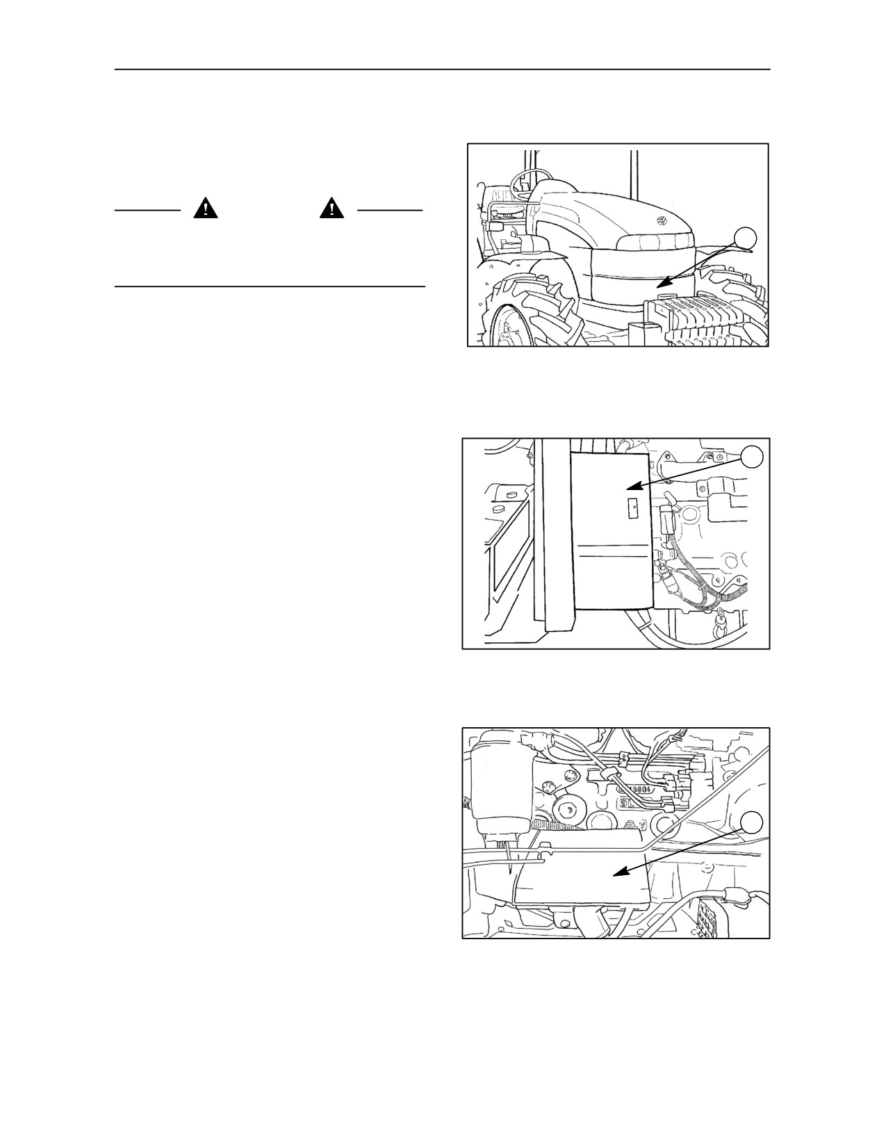
SECTION 2 -- CONTROLS, INSTRUMENTS AND OPERATION
SAFETY COVERS AND GUARDS
The tractor is fitted with covers and guards for the
personal safety of the operator and other people
when working.
CAUTION
Before starting the engine or using the tractor,
1
always check that all safety covers and guards are
correctly fitted.
BONNET (HOOD) -- Fig. 1
The hood (1) covers the engine’s moving parts.
1
It must be closed before the engine is started andthe
tractor is used.
FAN GUARD -- Fig. 2
1
Both sides of the fan have guards (1). The guard
shown protects the left--hand side of the fan.
TRE0022A
2
STARTER MOTOR COVER -- Fig. 3
The cover
(1) protects the electro--magnetic
contacts of the starter motor from accidental contact.
It must always be in place when the batteries are
connected to the electrical system.
1
The cover also protects the battery from possible
damage and the electrical connections from possible
accidental contact.
TRE0070A
3
2--2
SECTION 2 -- CONTROLS, INSTRUMENTS AND OPERATION
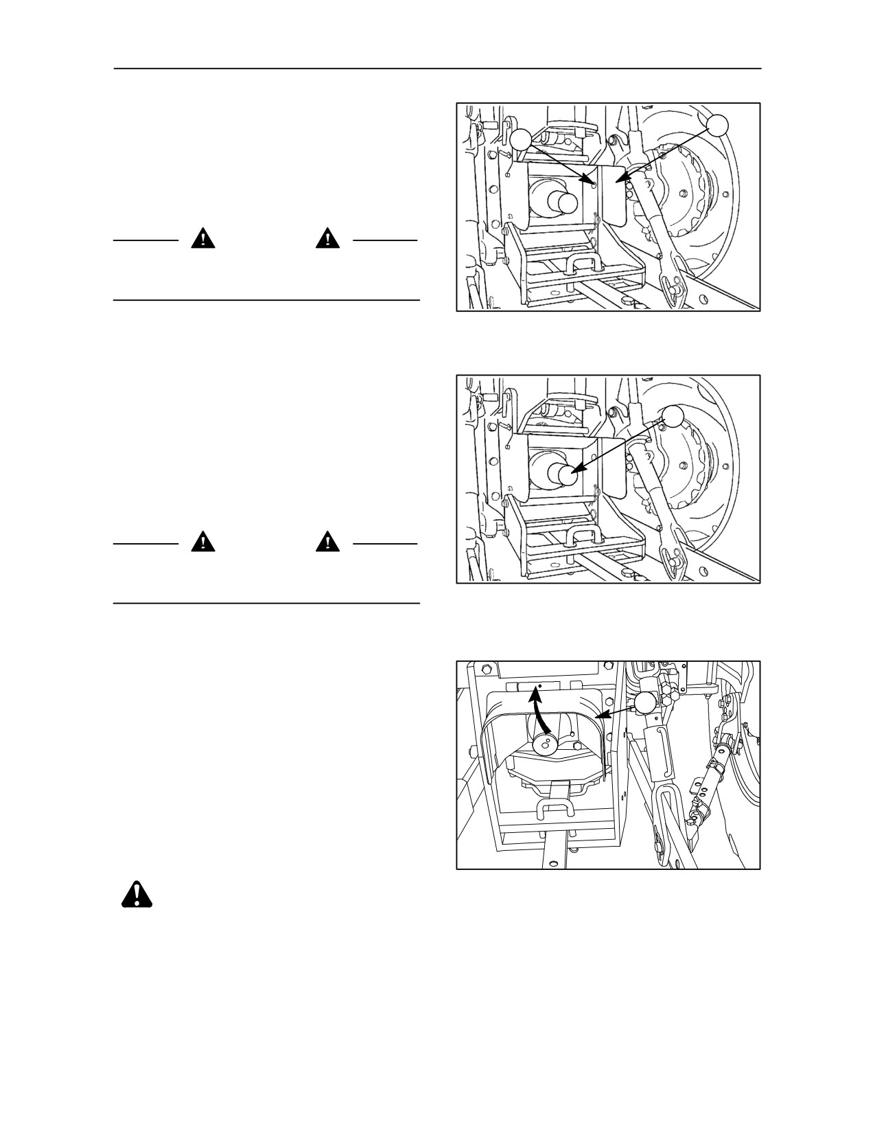
TRACTOR POWER TAKE--OFF GUARD --
Fig. 4
1
2
The guard (1) covers the power take--off shaft.
To facilitate shaft replacement, loosen screws (2)
and remove the guard.
CAUTION
The guard must never be removed when the tractor
is being used and must never be modified.
TRE0016A
4
POWER TAKE--OFF SHAFT SAFETY CAP --
Fig. 5
1
The cap (1) must always be fitted on the power
take--off shaft when it is not connected to an
implement.
Replace it correctly when the power take--off is not
in use.
CAUTION
Check that all guards and covers are correctly fitted
TRE0016A
before using the tractor.
5
PIVOTING POWER TAKE--OFF GUARD --
Fig. 6
1
The guard (1) protects the power take--off shaft.
NOTE: To facilitate connection of the tractor
transmission shaft / implement, lift the guard (1).
Once connected, return the guard to the safety
position.
TRE0801A
6
CAUTION: The guard must never be
removed when the tractor is being used and
must never be modified.
2--3
SECTION 2 -- CONTROLS, INSTRUMENTS AND OPERATION
CONTROLS AND INSTRUMENTS -- POSITION AND FUNCTION
The position and function of the controls and
--
Operating controls, left--hand side.
instruments on your tractor are described in the
following pages.
--
Foot pedal and foot plate controls.
The controls have been sub--divided into groups and
--
Cab controls.
are described as follows:
--
Instrument panel and console controls
CAUTION
Do not use the tractor if you are not fully acquainted
--
Instrument console (rear hood) controls
with the position and operation of all the tractor
controls.
--
Operating controls, right--hand side.
2--4
SECTION 2 -- CONTROLS, INSTRUMENTS AND OPERATION
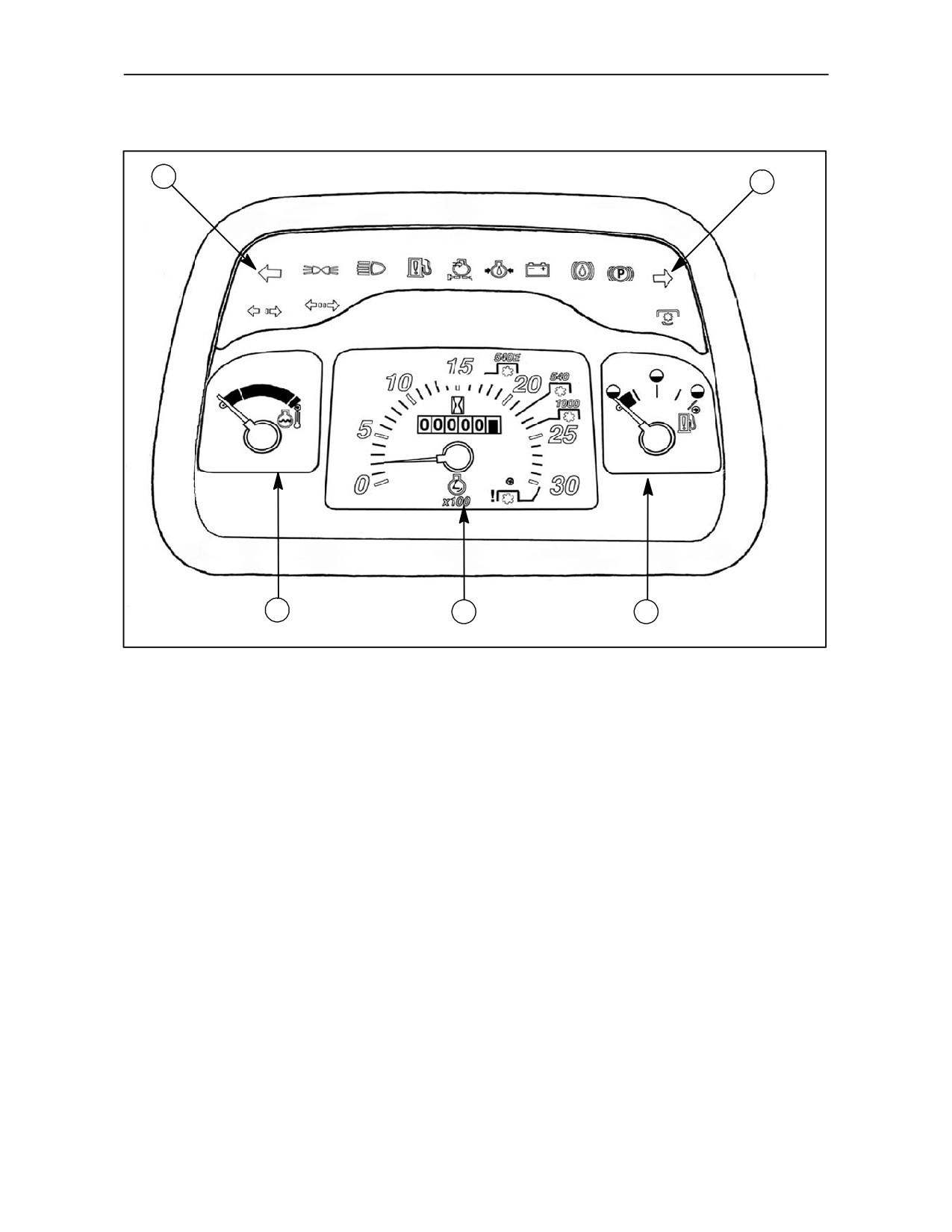
INSTRUMENT PANEL
1
1
2
3
4
TRE0027A
7
1. Warning and indicator lights
3. Proofmeter / tachometer
These lights illuminate to indicate a particular
Hourmeter, engine speed counter, tachometer.
operation or to attract your attention.
4. Fuel gauge
2. Engine coolant temperature gauge
2--5
SECTION 2 -- CONTROLS, INSTRUMENTS AND OPERATION
1
2
3
4
5
6
7
TRE0073A
8
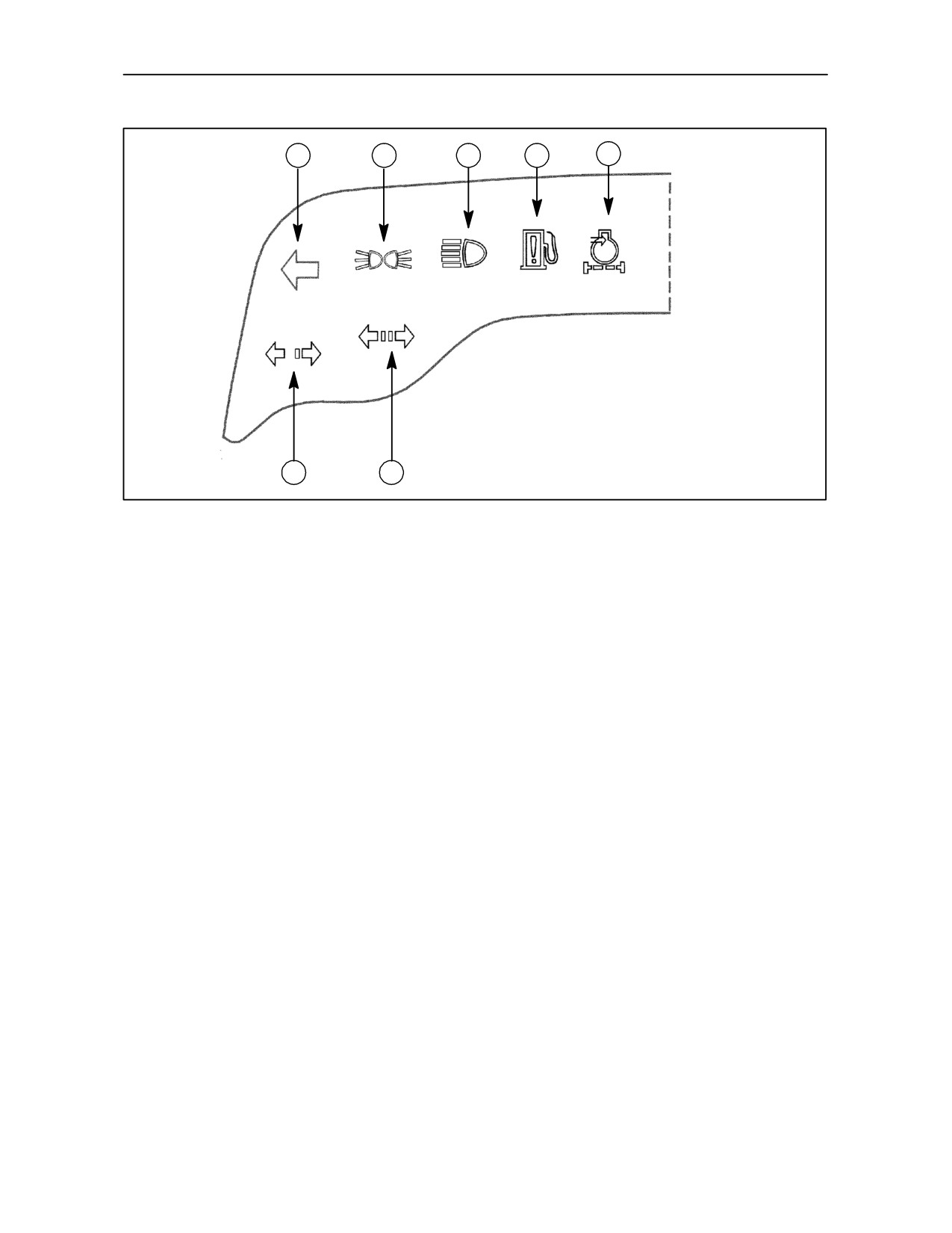
1. Tractor left turn indicator (green)
5. Dry air filter clogged warning light (yellow)
Flashes in unison with the tractor left turn indicators.
The light comes on when the air filter cartridge is
partially or totally clogged. Clean the filter, as
2. Side lights indicator (green)
described in section 4, operation 6.
Lights up when the side lights are switched on.
6. First trailer turn indicator lights (green)
3. Main beam indicator (blue)
Flashes in unison with the tractor turn indicators, if
connected.
The light illuminates when the headlights are on main
beam.
7. Second trailer turn indicator lights (green)
Flashes in unison with the tractor turn indicators, if
4. Water in fuel indicator (green)
connected.
The light illuminates to indicate that the fuel in the
filter bowl is clogged. Clean the filter, as described in
section 4, operation 8.
2--6
SECTION 2 -- CONTROLS, INSTRUMENTS AND OPERATION
1
2
3
4
5
6
TRE0072A
9
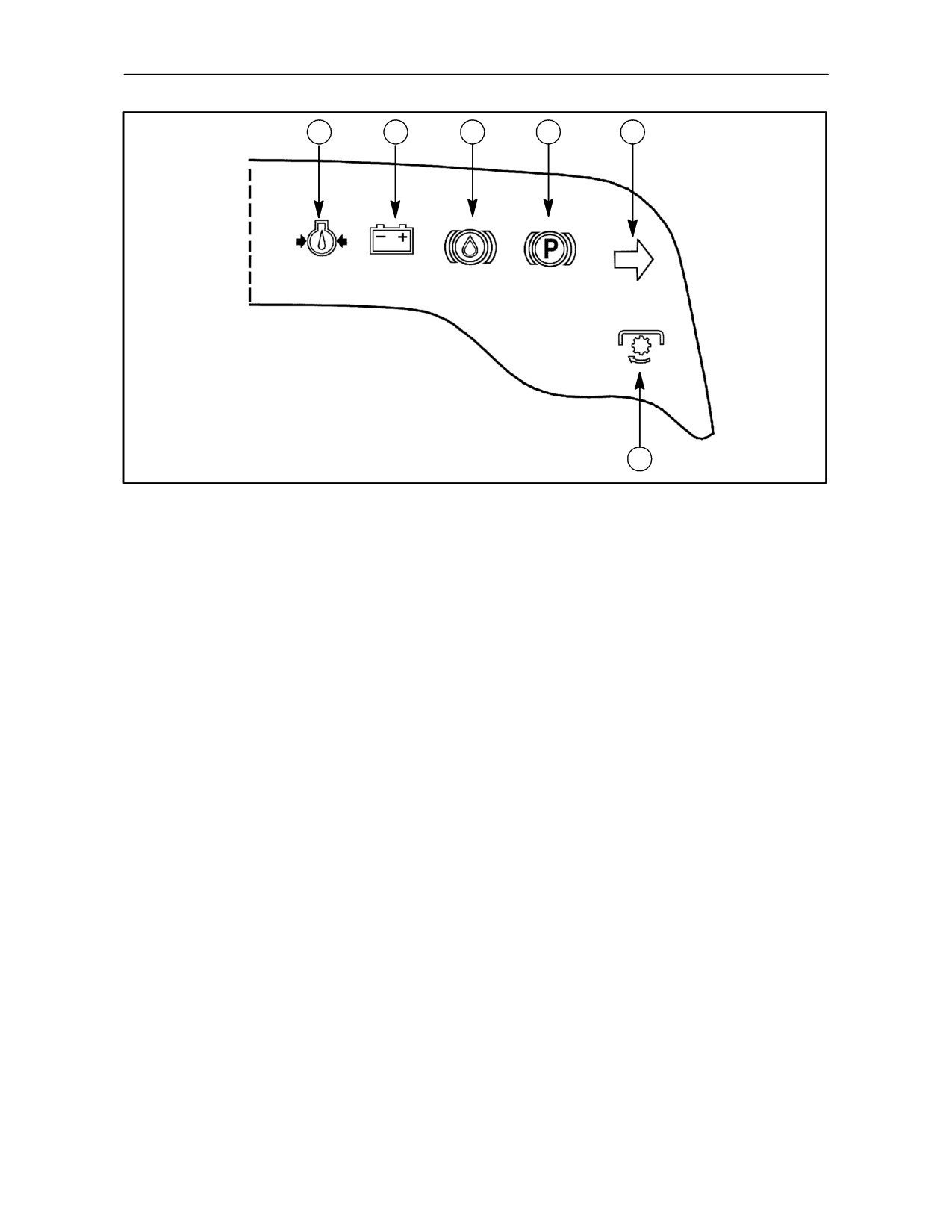
1. Low engine pressure indicator (red)
3. Low front brake fluid level indicator.
The light should go out a few seconds after the
Comes on when the fluid drops below “MIN” level.
engine is started.
Check periodically that the light is working properly.
If it staysonwhentheengineisrunning,switchoffthe
With the ignition key in the first position, press the lid
engine and look for the cause of the problem. If the
on the brake fluid reservoir; the indicator should light
light remains on, particularly when the tractor is
up.
moving, contact your dealer. When the engine is
warmed up and running at minimum speeds, with the
4. Handbrake ON light (red)
tractor stationary, the light may illuminate, even if no
faults are present.
With the ignition key turned on, the light comes on
when the handbrake is applied.
2. Battery charging system malfunction light
(red)
5. Tractor right turn indicator (green)
It should go out once the engine starts.
Flashes in unison with the tractor right turn
indicators.
6. Not used on this tractor range.
2--7
SECTION 2 -- CONTROLS, INSTRUMENTS AND OPERATION
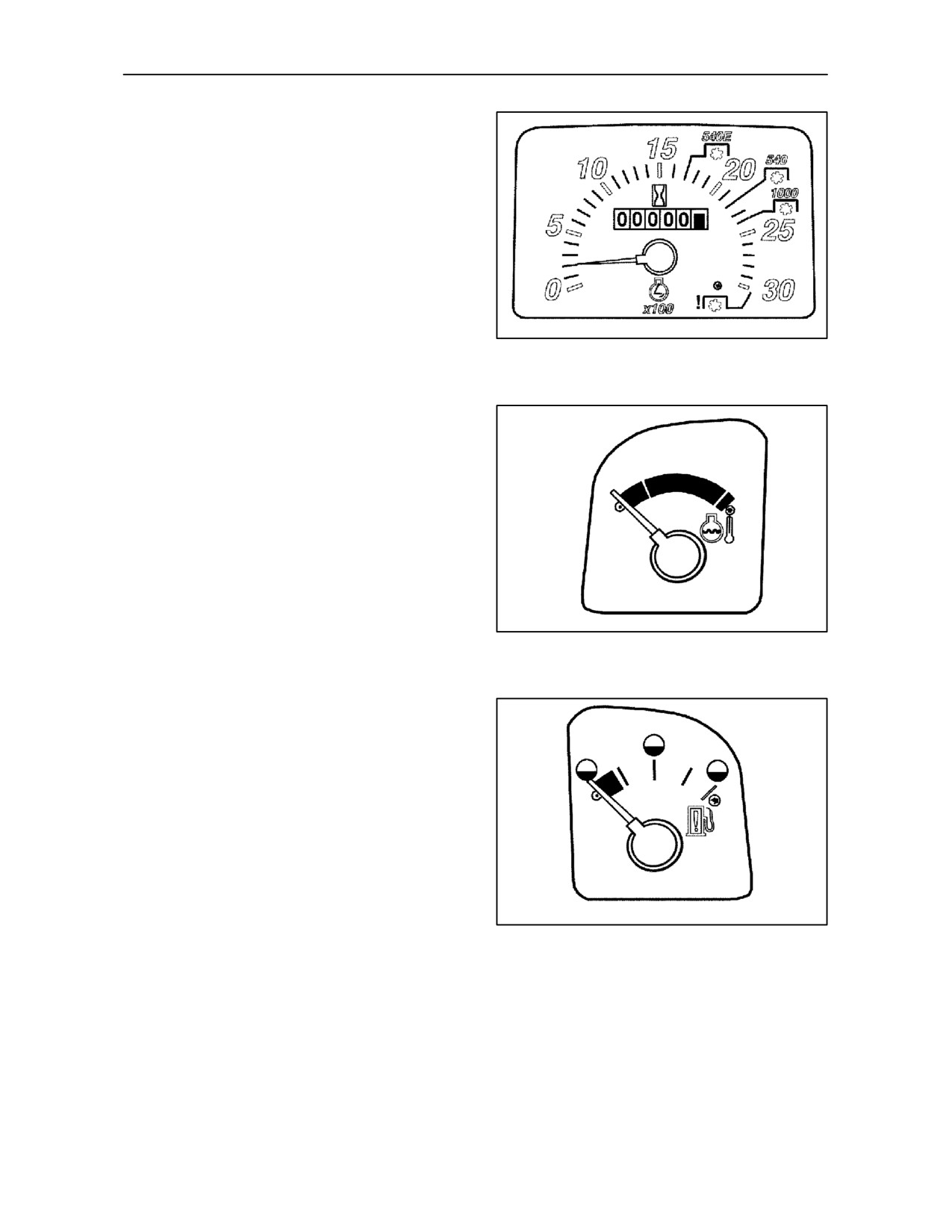
1. Proofmeter / tachometer -- Fig. 10
This shows engine speed and total time to a
maximum of six digits. The figures on the black
background show total working hours and those on
the red background (extreme right) tenths of an hour.
The green and blue sectors show the engine rev/min
reached at standard power take--off speeds of 540,
540E and 1000 rev/min.
TRE0076A
10
2. Engine coolant temperature gauge -- Fig. 11
--
Green area = normal temperature.
--
White area = temperature too low.
--
Red area = engine overheating
In this case, slow the engine to minimum revs (donot
stop it) and, if the light stays on, have the cooling
system checked.
TRE0075A
11
3. Fuel gauge -- Fig. 12
It shows the fuel level in the tank.
When the tank is full, the needle is at the extreme
right.
When the fuel level falls below1/4, the needle moves
into the red area.
TRE0074A
12
2--8
SECTION 2 -- CONTROLS, INSTRUMENTS AND OPERATION
MULTI--FUNCTION CONTROL
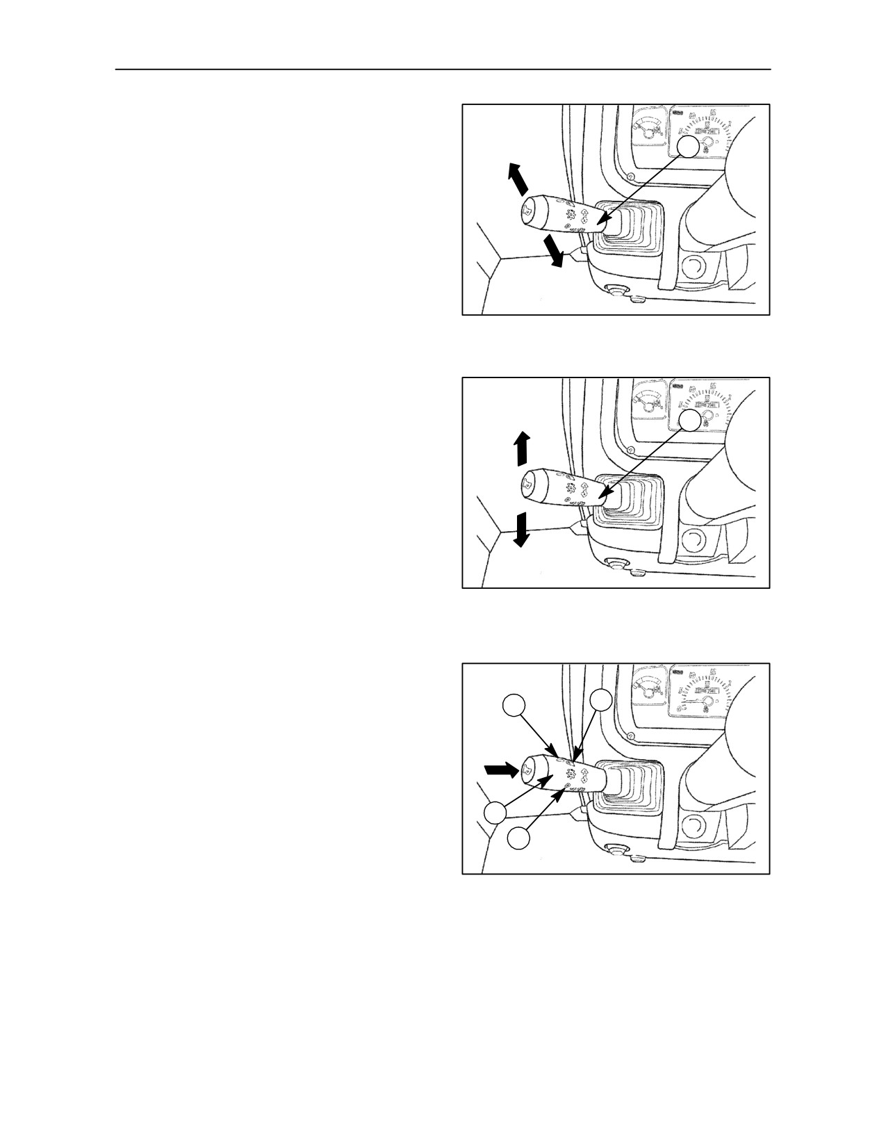
The multi--function stalk controls the lights, horn, turn
1
A
indicators and headlight flasher and is also used to
switch from dipped to main beam front headlights.
Direction indicators
To indicate a right turn, push the stalk (1), fig. 13,
forward to position A.
B
To indicate a left turn, pull the stalk (1), fig. 13, back
TRE0067A
to position B.
13
Flashing front headlights
With the lights off or on, move the stalk up to position
A
1
A fig. 14 to flash the main beam headlights. When
the stalk is released, it automatically returns to its
original position.
B
NOTE: The stalk switch (1) fig. 14 will only operate
with ignition key in position B fig. 1, page 3--3.
Side lights
C
TRE0067A
With the stalk (1) fig. 14 in position B, rotate the outer
end of the stalk so that the indicator (1) fig. 15 aligns
14
with symbol (2), the side lights ‘on’ symbol.
Dipped headlights
With the stalk (1) fig. 14 in position B, rotate the outer
end of the stalk so that the indicator (1) fig. 15 aligns
3
1
with symbol (3), the headlights ‘on’ symbol.
Main beam headlights
With the indicator (1) fig. 15 aligned with symbol (3),
the headlights ‘on’ symbol, move the stalk down to
2
position C, as shown in fig. 14. The main beam
warning light on the instrument panel will illuminate
4
with the main beam headlights.
TRE0067A
Horn
15
Press the end of control (2) on the stem as shown by
the arrow in fig. 15.
NOTE: When the indicator (1) fig. 15 is aligned with
symbol (4) all the lights are off. Only the direction
indicators and the horn are still functional.
2--9
SECTION 2 -- CONTROLS, INSTRUMENTS AND OPERATION
INSTRUMENT PANEL AND CONSOLE CONTROLS
TRE0027A
16
INSTRUMENT CONSOLE CONTROLS --
1
Fig. 17
2
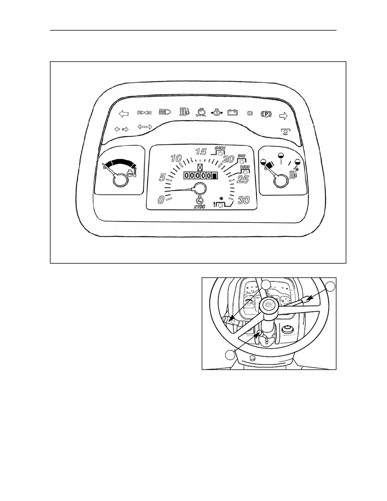
1. Lights control lever
The lever operates external lights, horn and the
direction indicators.
2. Hand throttle lever
--
Pushed fully forward; min. engine speed
3
TRE0083A
--
Pulled fully backward; max. engine speed
17
3. Steering wheel position lever
Push lever (3) to release the steering wheel lock.
Move the steering wheel up or down to find the best
position for comfortable and safe driving. Pull the
lever to lock the steering wheel in the required
position.
2--10
SECTION 2 -- CONTROLS, INSTRUMENTS AND OPERATION
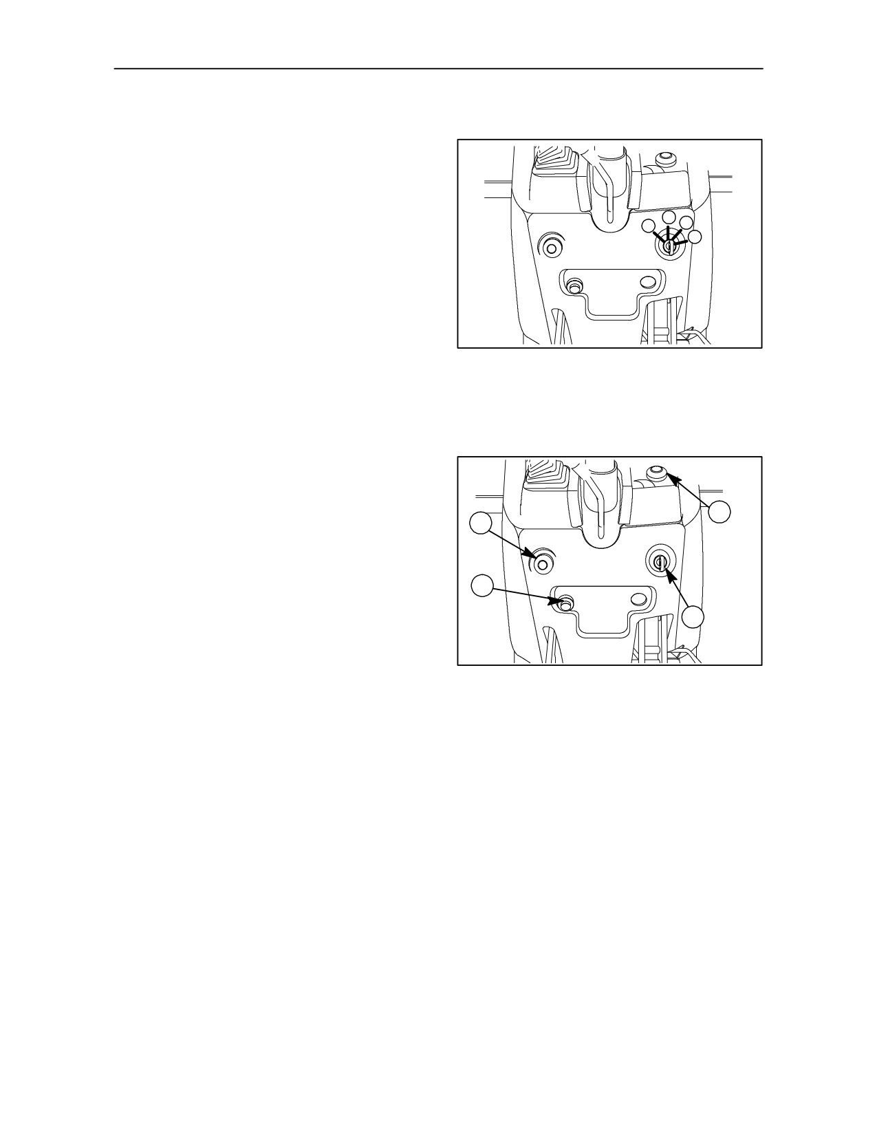
INSTRUMENT CONSOLE CONTROLS
IGNITION KEY -- Fig. 18
To operate the four key functions, turn the key (1),
fig. 19, through the following positions:
A
P
B
A. No power to circuits (key can be removed).
C
Engine stopped: automatic activation of fuel
injection cut--off.
B. Engine start presetting: operation of panel lights
and instruments. Power supplied to various
circuits.
18
C. Starting the engine: when released, the key
returns automatically to position (B).
P. Parking lights on: instrument panel lighted
(key removable)
CONSOLE CONTROLS -- Fig. 19
2-- Thermostart.
3
2
3-- Hazard warning light switch.
4-- Cigarette lighter.
4
1
19
2--11
SECTION 2 -- CONTROLS, INSTRUMENTS AND OPERATION
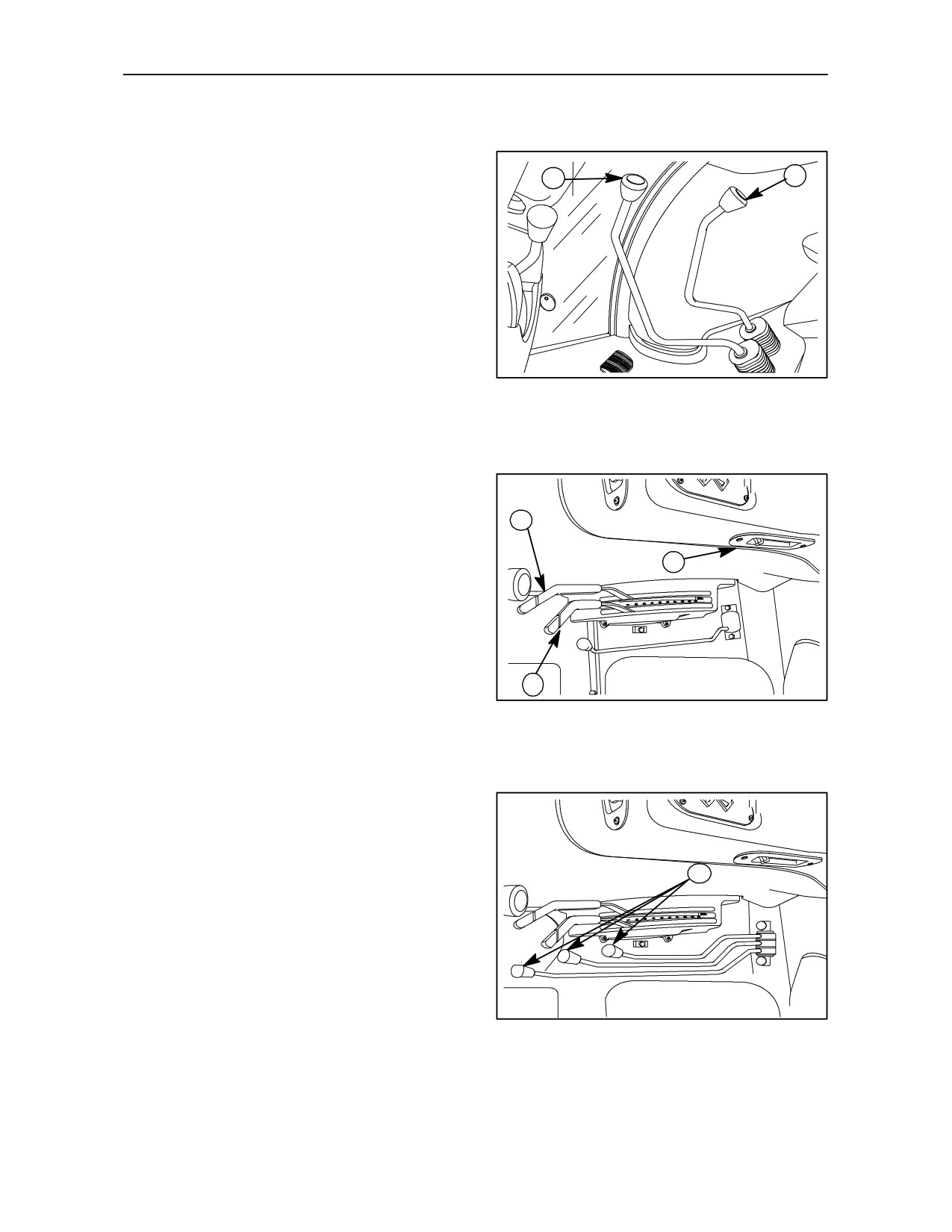
RIGHT--HAND SIDE OPERATING CONTROLS
Fig. 20
1
2
1. Main shift lever
2. Range lever
20
Fig. 21
1. Hydraulic lift operating (position control) lever
1
2. Hydraulic lift operating (draft control) lever
3
3. Fast
hydraulic
lift
up/down control
(Lift--O--MaticTM).
2
21
Fig. 22
1. Remote control valve levers
1
22
2--12
SECTION 2 -- CONTROLS, INSTRUMENTS AND OPERATION
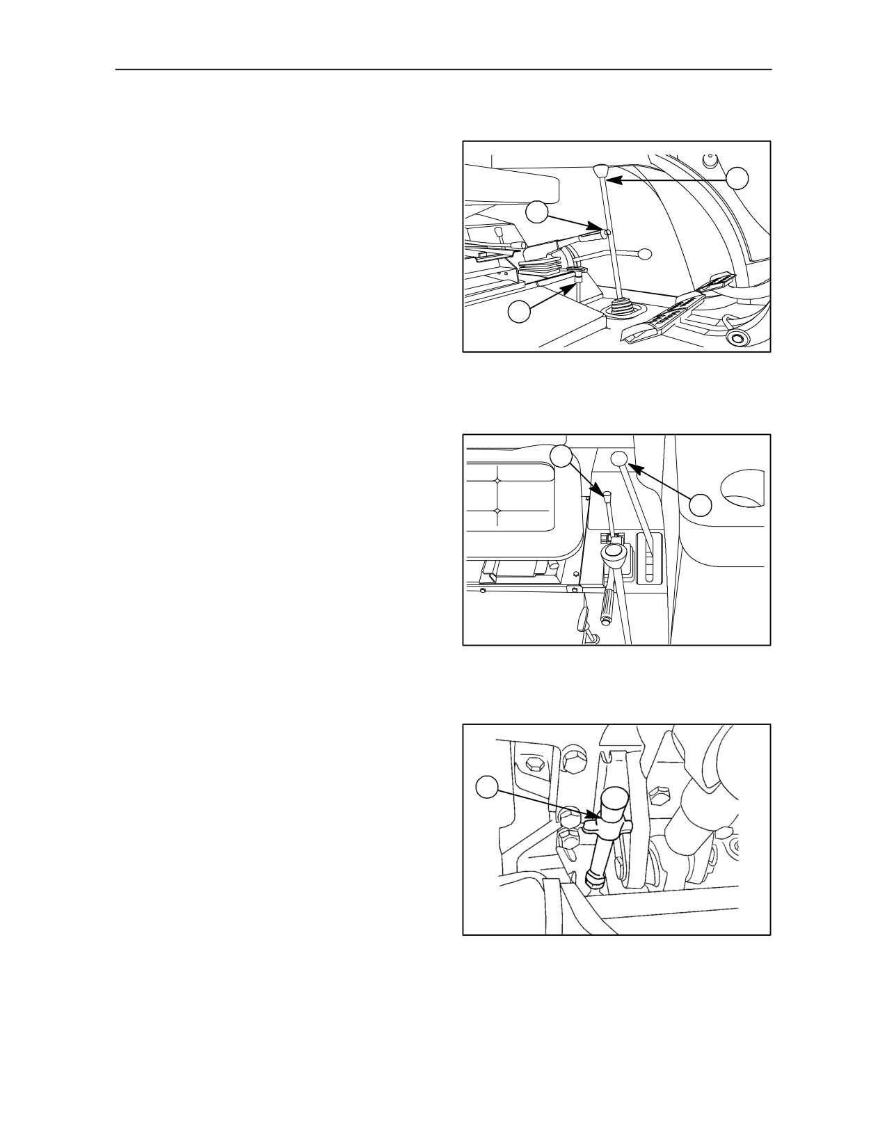
LEFT--HAND SIDE OPERATING CONTROLS
Fig.
23
1. Shuttle lever
1
2. Handbrake lever (with push button release)
2
--
up = brake on;
--
down (horizontal) = brake off.
3. Mechanically controlled four--wheel drive lever
3
--
pulled upwards: engaged
23
--
pushed downwards: disengaged
Fig. 24
1
1. Standard power take--off operation selector lever
2. Power take--off engagement lever
2
24
Fig. 25
1. Power take--off speed selector lever
1
TRE0002C
25
2--13
SECTION 2 -- CONTROLS, INSTRUMENTS AND OPERATION
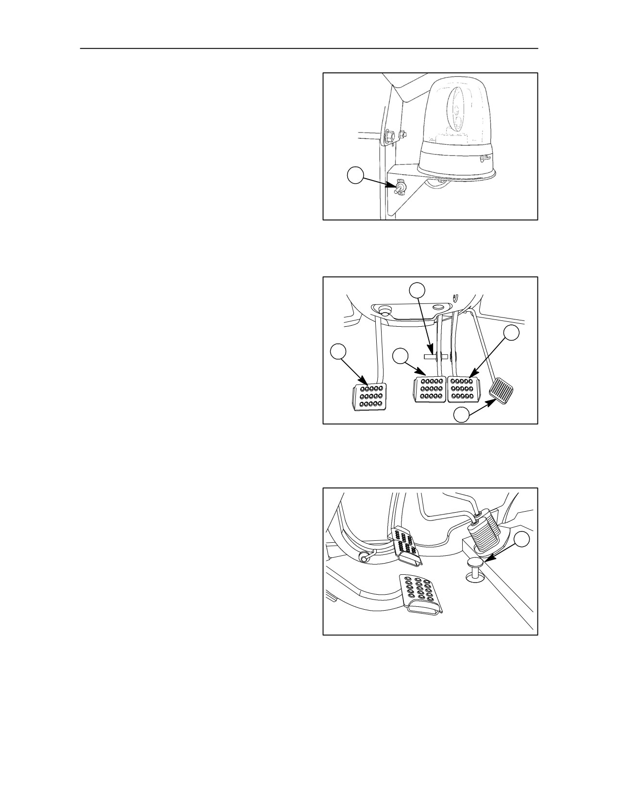
ROTATING BEACON -- Fig. 26
1. Beacon on/off switch (less cab models)
1
TRE0020A
26
PEDAL CONTROLS -- Fig. 27
4
1. Foot throttle.
2. Right brake control pedal.
2
3. Left brake control pedal.
5
3
4. Brake pedal lock pin.
5. Transmission clutch pedal.
1
27
Fig.
28
1. Rear mechanical differential lock
1
28
2--14
SECTION 2 -- CONTROLS, INSTRUMENTS AND OPERATION
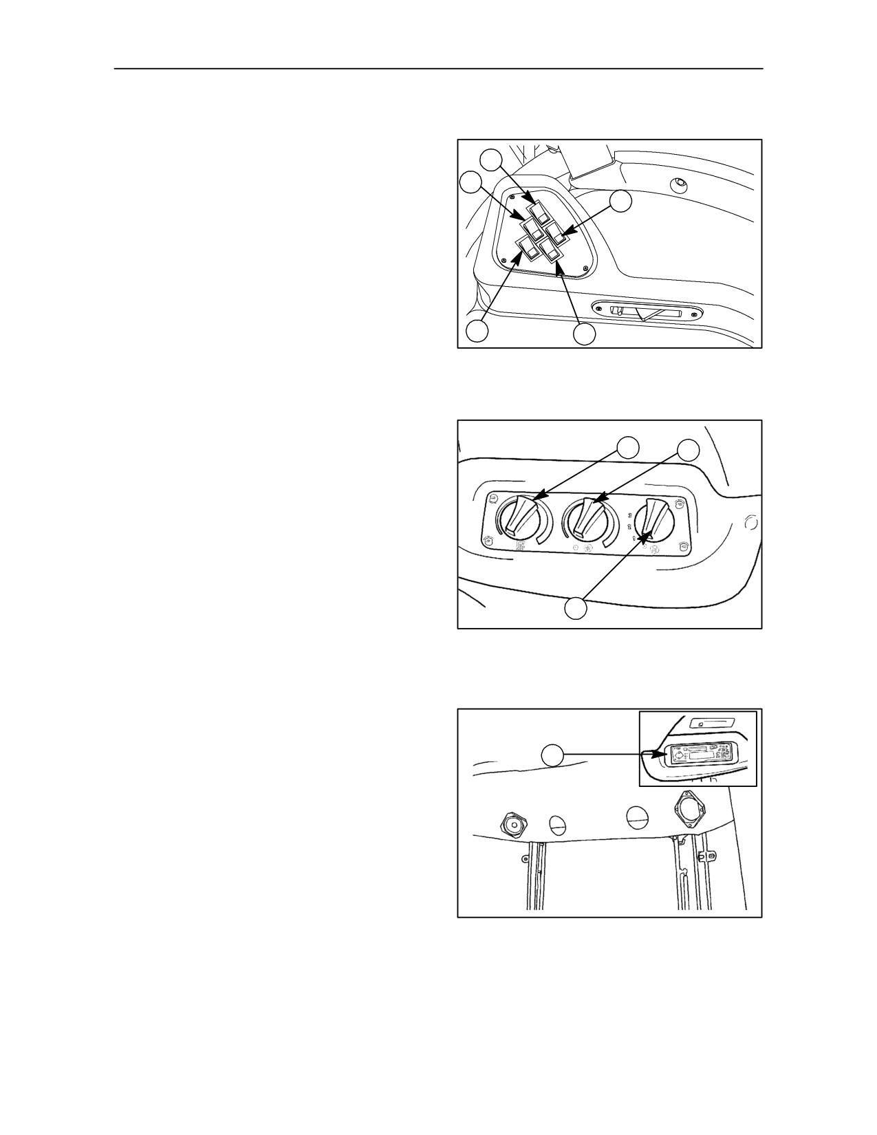
CAB CONTROLS
RIGHT--HAND MUDGUARD CONTROLS --
Fig. 29
4
2
1. Windscreen washer switch
3
2. Windscreen wiper switch
3. Rear work lights switch
4. Front work lights switch
5. Roof beacon switch (with cab)
1
5
29
HEATING AND AIR--CONDITIONING
CONTROLS -- Fig. 30
2
3
1. Heater/air--conditioner fan speed control
2. Heat temperature control
3. Air--conditioning temperature control
1
TRE0012A
30
RADIO/CASSETTE PLAYER (OPTIONAL) --
Fig. 31
1
1. Radio / Cassette player
TRE0021A
31
2--15
SECTION 2 -- CONTROLS, INSTRUMENTS AND OPERATION
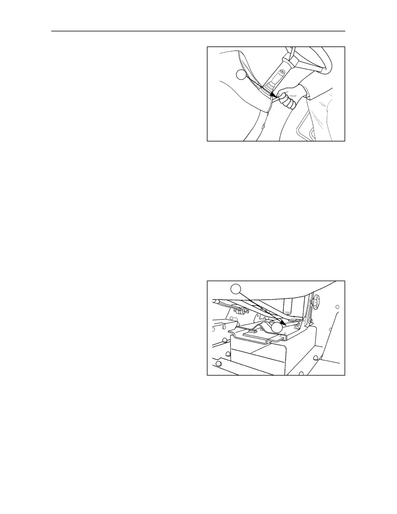
STEERING COLUMN ADJUSTMENT --
Fig. 32
The steering is fitted with a lever for tilt adjustment.
1
To adjust the steering wheel, use lever (1) fig. 32.
When adjusted satisfactorily, lock the lever by
pushing it upwards.
1. Steering wheel tilt adjustment
--
Lever down, steering column released;
TRE0010A
32
--
Lever up, steering column locked in position.
SEATS
Even under difficult conditions, adjust your seat for
--
check periodically that the securing screws are
tight and that the adjustment controls are
safe driving. To avoid danger, follow the instructions
working properly to ensure safety and stability
below:
when working.
--
do not adjust the seat when the tractor is moving;
--
the driver’s seat must be fitted and repaired by
specialist personnel only.
Standard seat -- Fig. 33
1
The driver’s seat has adjusters for its suspension,
height and distance from the controls.
You can therefore select the most suitable position
for driving, and even change it while working.
--
To move the seat forward or back, pull the lever
(1) sideways.
--
After moving the seat, release the lever, ensuring
TRE0056A
that the seat is locked in the chosen position.
33
2--16
SECTION 2 -- CONTROLS, INSTRUMENTS AND OPERATION
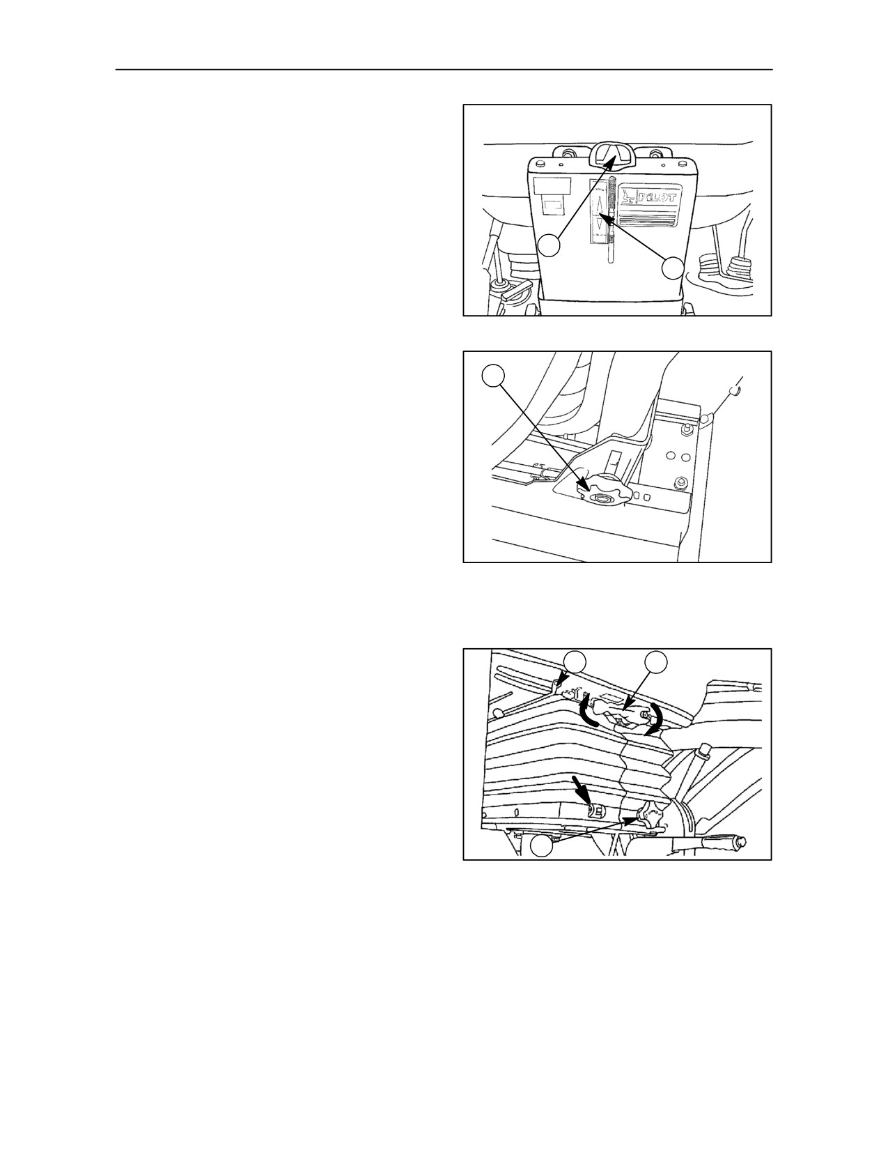
SEAT SUSPENSION ADJUSTMENT -- Fig. 34
For correct adjustment, turn knob (1) clockwise or
counter--clockwise until, with the driver seated, the
indicator aligns with the centre of the arrows (2).
1
2
TRE0055A
34
SEAT HEIGHT ADJUSTMENT -- Fig. 35
1
To raise the seat, loosen knobs (1) (one on each side)
and position the seat at the most suitable height.
Tighten the knobs after adjustment.
TRE0057A
35
SEAT (OPTIONAL) -- Fig. 36
2
1
Adjustment of distance from controls
From the driver’s seat, pull lever (2) sideways and
move the seat forwards or backwards.
After moving the seat, release the lever and check
that the seat is locked in the correct position.
Seat height adjustment
TRE0082A
3
To raise or lower the seat, turn the handle (1)
36
clockwise or counter--clockwise, as shown in the
illustration.
Seat suspension adjustment
For correct suspension adjustment, turn knob (3)
clockwise or counter--clockwise until your weight
appears in the port indicated by the arrow in the
illustration.
2--17
SECTION 2 -- CONTROLS, INSTRUMENTS AND OPERATION
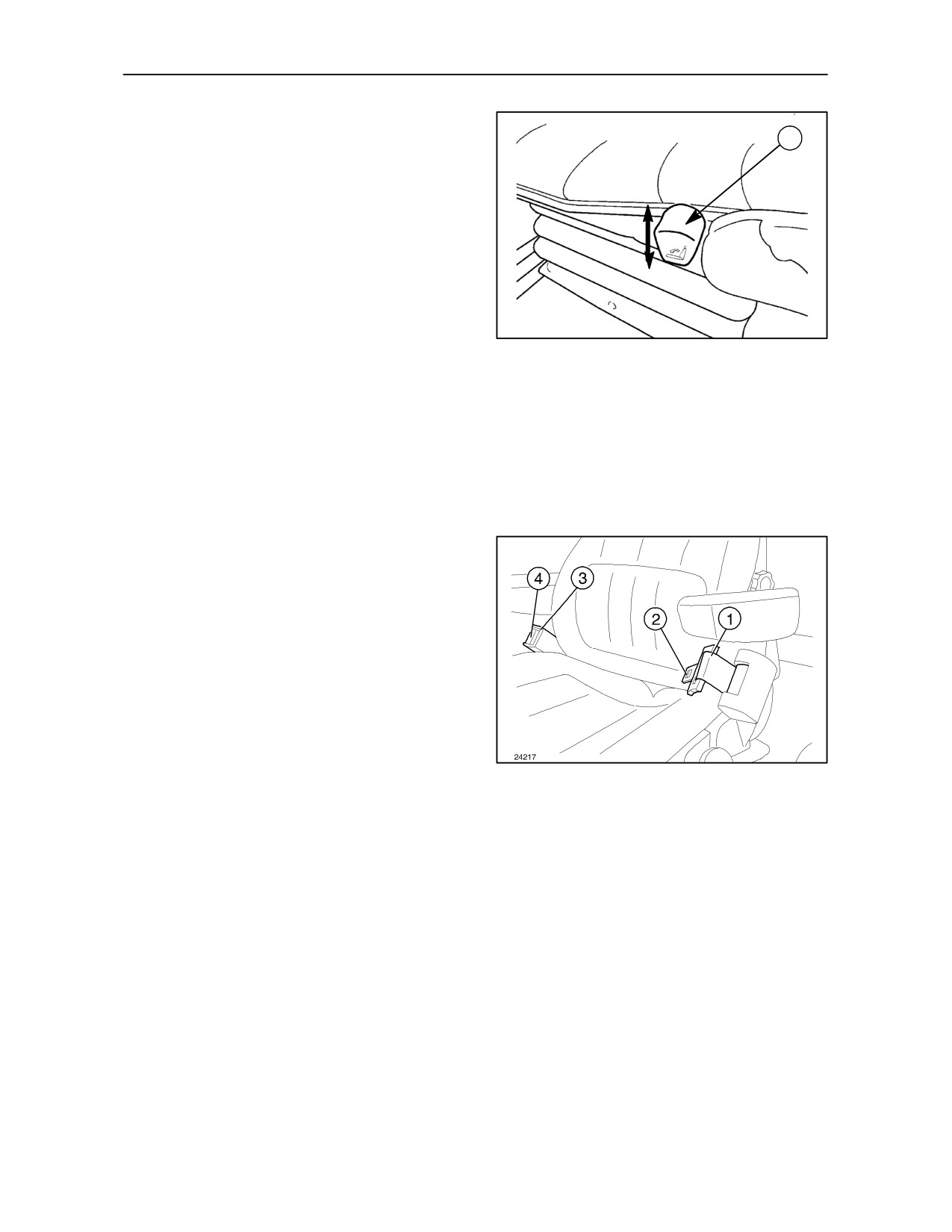
Seat backrest adjustment -- Fig. 37
1
Push the lever (1) down to adjust the backrest.
Release the lever to lock the backrest in the selected
position.
TRE0054A
37
SEAT BELT (OPTIONAL)
The belt with inertia--reel device for De--Luxe seats
and for air--sprung seats is available.
INERTIA--REEL SEAT BELT -- Fig. 38
To fasten belt (1) pull it from the inertia--reel device
and insert tongue (2) into slot (3).
NOTE: The belt adjusts automatically to the driver’s
body.
To unfasten it, press and then release button (4).
The belt reels in automatically.
38
2--18
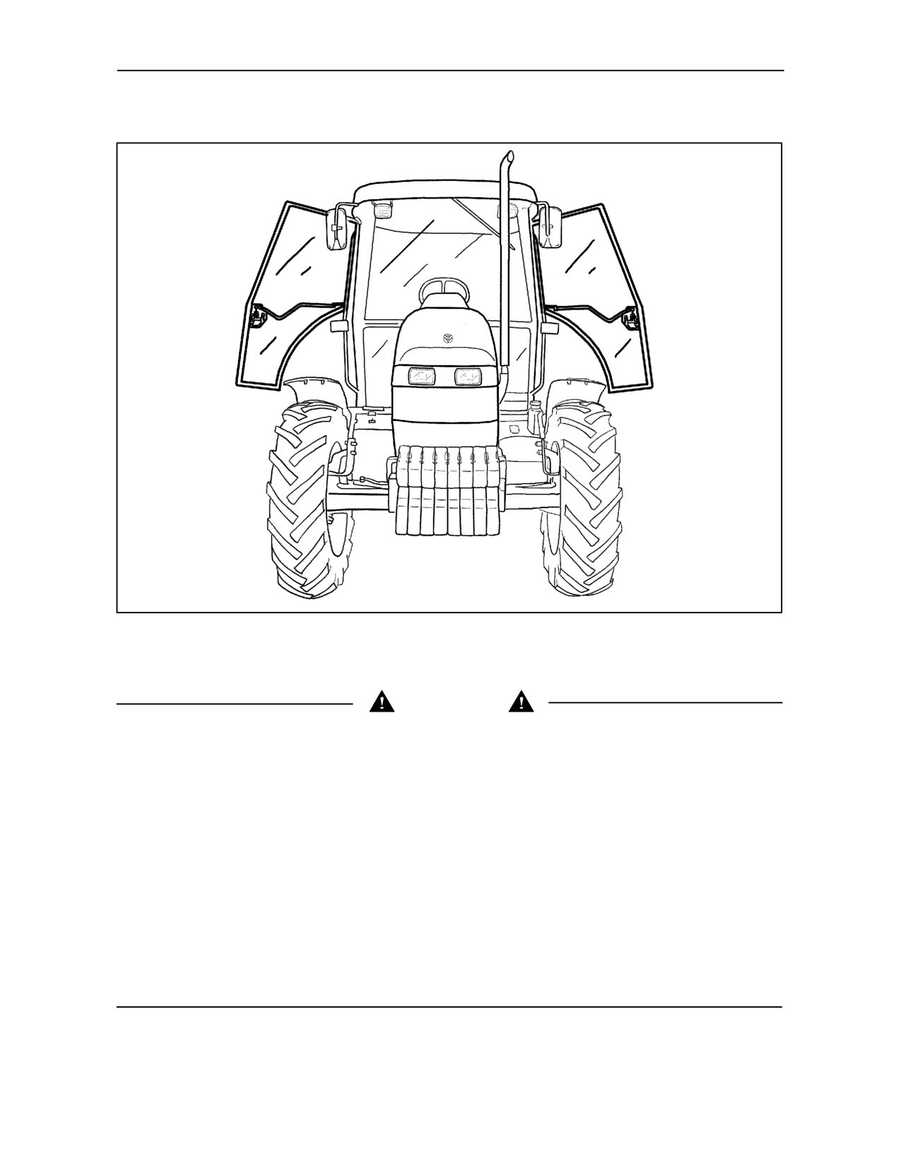
SECTION 2 -- CONTROLS, INSTRUMENTS AND OPERATION
CAB
TRE0013A
39
This section of the Manual deals only with the use of the heated and ventilated cab.
ATTENTION
The cab is an integral part of the Structure of the Tractor.
The cab structure must in no way be modified
It is therefore prohibited to drill, weld or anyhow connect any device to it that would impair its intended operation.
Any damage due to accident, fire, theft or corrosion to the original structure could make it inefficient and lessen
its safety.
It is therefore necessary for specialized personnel to evaluate the damage and, if necessary, have the damaged
parts replaced.
All the internal parts, such as the operator’s seat, including any seat belts, must be carefully checked and must
show no sign of any damage whatsoever.
--
The cab must be replaced in the event of overturning.
--
All the internal parts, such as the operator’s seat, including any seat belts, must be carefully checked and
must show no sign of any damage whatsoever.
--
All damaged parts must be replaced.
IN THE EVENT OF OVERTURNING, DO NOT ATTEMPT TO REPAIR, WELD OR STRAIGHTEN THE CAB,
contact your Dealer’s specialized personnel instead
2--19
//////////////////////////////////////////