New Holland TD 60D, TD 70D, TD 80D, TD 90D, TD 95D Tractor. OPERATOR’S MANUAL - page 5

SECTION 4 -- LUBRICATION AND MAINTENANCE
LUBRICANT CAPACITIES AND SPECIFICATIONS
QUANTITY
NEW HOLLAND
COMPONENT TO BE FILLED OR
INTERNATIONAL
RECOMMENDED
TOPPED UP
SPECIFICATION
litres/dm3
US gal
IMP gal
PRODUCTS
Cooling system:
models TD60, TD70
12
3.2
2.64
Water & liquid
models TD80, TD90, TD95
14
3.7
3.08
AMBRA AGRIFLU
--
with cab:
50% + 50%
models TD60, TD70
14
3.7
3.1
(NH 900 A)
models TD80, TD90, TD95
16
4.2
3.5
Water & cleaning
Windscreen washer bottle
2
0.53
0.44
--
liquid
Decanted and
Fuel tank
92
24.3
20.2
filtered
--
diesel fuel
Engine sump:
without filter :
AMBRA Supergold
SAE 15W -- 40
TD60 and TD70
7.6
1.98
1.67
(NH 330G)
TD80, TD90andTD95
10.5
2.77
2.31
API CF--4/SG
AMBRA Supergold
with filter :
CCMC D4
SAE 10W -- 30..
MIL--L--2104E
TD60 and TD70 HP models
8.3
2.19
1.83
(NH 324G)
TD80, TD90 andTD95models
11.2
2.96
2.46
AMBRA BRAKE
Brake control circuit
0.4
0.1
0.09
ISO 7308
LHM Oil (NH 610 A)
Hydrostatic steering circuit
2.0
0.5
0.44
Front axle:
-- axle housing:
models TD60, TD70
4.5
1.2
0.99
models TD80, TD90, TD95
7.0
1.8
1.54
-- final drives (each):
models TD60, TD70
0.8
0.2
0.18
models TD80, TD90, TD95
1.25
0.3
0.28
Rear transmission (bevel drive and
Oil
API GL4
brakes), gearbox, hydraulic lift and
AMBRA MULTI G
ISO 32/46
PTO
(NH 410B)
SAE 10W--30
models TD60,TD70, TD80, TD90,
TD95
46
12.15
10.12
-- with synchro--reverser:
models TD60, TD70, TD80,
TD90, TD95
46
12.15
10.12
Rear final drives (each)
models TD60, TD70
3.9
1.03
0.86
models TD80, TD90 and TD95
5.3
1.40
1.17
Front wheel hubs
--
--
--
Grease
AMBRA GR9
NLGI 2
Grease fittings
--
--
--
(NH 710A)
4--41
SECTION 4 -- LUBRICATION AND MAINTENANCE
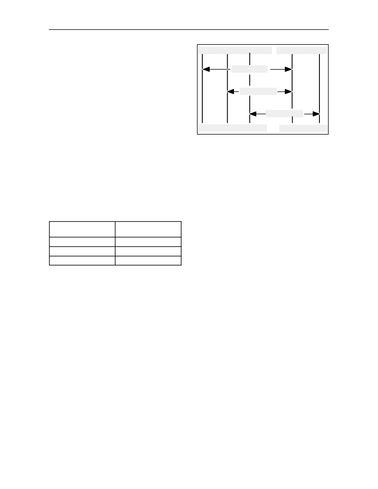
Refer to the chart on the right when selecting the oil
--30OC
--25OC
--15OC
+20OC
+40OC
grade for your tractor engine.
SAE 5W--30
SAE 10W--30
SAE 15W--40
NOTE: In areas where prolonged periods of extreme
--22OF
--13OF
+5OF
+68OF
+104OF
temperatures are encountered, local lubricant
89
practices are acceptable; such as the use of SAE 5W
in extreme low temperatures or SAE 50 in extreme
high temperatures.
Sulphur in Fuel
The engine oil change period is shown in Operation
27 on page 4--19. However, locally available fuel may
have a high sulphur content, in which case the engine
oil change period should be adjusted as follows:
Oil
Sulphur Content %
Change Period
less than 0.5
normal
0.5 to 1.0
half the normal
above 1.0
one quarter normal
The use of fuel with a sulphur content above 1.3% is
not recommended.
4--42
SECTION 5
FAULT FINDING
LOCATING AND IDENTIFYING PROBLEMS
INTRODUCTION
The following information is intended to help in the identification and correction of any tractor faults or
malfunctions.
PROBLEM CODES -- AREAS AFFECTED
The following information lists problems which could arise, the reasons for them and appropriate corrective
action. The areas affected are dealt with in the following order:
Engine
Hydraulic System
Brakes
Electrical system
Hydraulic lift
Cab
5--1

SECTION 5 -- FAULT FINDING
ENGINE
PROBLEM
POSSIBLE CAUSE
SOLUTION
The engine will not start or is
Incorrect starting procedure.
See starting procedure.
difficult to start.
Fuel level low or empty.
Check fuel level.
Air in fuel system.
Bleed fuel system.
Engine oil viscosity not right.
Use oil of right viscosity.
Fuel not suitable for ambient
Use correct type of fuel for
temperature.
temperature conditions.
Fuel system contaminated.
Clean system.
Fuel filter clogged.
Replace filter element.
Fuel injector fault.
Contact your dealer.
The engine does not run
Fuel system contaminated.
Clean system.
properly and/or cuts out.
Fuel injector fault.
Contact your dealer.
Engine does not reach
Engine overload.
Change to lower gear or
maximum power.
reduce load.
Air filter clogged.
Carry out maintenance on air
filter.
Incorrect fuel type.
Use the right fuel.
Low engine operating tempera-
Check thermostat.
ture.
Fuel injector fault.
Have your dealer check the
injectors.
Implement incorrectly set.
See equipment manual.
5--2

SECTION 5 -- FAULT FINDING
ENGINE
PROBLEM
POSSIBLE CAUSE
SOLUTION
Engine does not reach maxi-
Valve clearance wrong.
Check and adjust.
mum power (cont.).
Idling speed too low.
Contact your dealer.
Abnormal engine knocking.
Oil level low.
Top up oil.
Oil pressure low.
Contact your dealer.
Low engine operating tempe-
Thermostat malfunction.
Replace thermostat.
rature.
Oil pressure low.
Oil level low.
Add oil as required.
Oil grade or viscosity wrong.
Drain and refill with oil of
correct grade and viscosity.
Excessive oil consumption.
Oil level too high.
Reduce oil level.
Oil viscosity wrong.
Use oil of correct viscosity.
Oil leaking.
Repair leaks.
Breather pipe filter clogged.
Replace breather pipe filter.
Engine overheating.
Radiator core clogged.
Clean.
Engine overload.
Change to lower gear or
reduce load.
Engine oil level low.
Top up oil level.
Coolant level low.
Top up fluid level in expansion
tank; check system for leaks.
Radiator cap defective.
Replace cap.
Fan belt slipping or worn.
Check tensioning device;
replace belt if worn.
5--3

SECTION 5 -- FAULT FINDING
ENGINE
PROBLEM
POSSIBLE CAUSE
SOLUTION
Engine overheating.
Cooling system clogged.
Flush cooling system.
Thermostat malfunction.
Check thermostat.
Hoses leaking.
Tighten hose connectors.
Temperature indicator or
Contact your dealer.
gauge malfunction.
Excessive fuel consumption.
Wrong fuel type.
Use right fuel type.
Air filter dirty or clogged.
Carry out maintenance on air
filter.
Engine overload.
Change to lower gear or
reduce load.
Valve clearance wrong.
Check and adjust.
Equipment wrongly adjusted.
Refer to equipment manual for
correct operation.
Engine temperature too low.
Check thermostat.
Too much ballast.
Adjust ballast to correct
weight.
Fuel injection nozzles clogged.
Have your dealer service the
injectors.
5--4

SECTION 5 -- FAULT FINDING
ELECTRICAL SYSTEM
PROBLEM
POSSIBLE CAUSE
SOLUTION
The electrical system does not
Battery terminals loose or
Clean and tighten terminals.
work.
corroded.
Sulphated battery.
Check that battery charge is at
least 12.6 volts; check electro-
lyte level and specific gravity.
Low starter motor speed and
Connections loose or corro-
Clean and tighten loose con-
difficulty in starting engine.
ded.
nections.
Battery.
Check that battery charge is at
least 12.6 volts; check electroly-
te level and specific gravity.
Engine oil viscosity wrong.
Use oil of viscosity specified
for temperature conditions.
Starter motor does not work.
Gear lever engaged.
Move gear lever to neutral.
Connections loose or corro-
Clean and tighten loose con-
ded.
nections.
Battery totally flat.
Charge or replace battery.
Battery charge light stays on
Engine idling speed is low.
Increase idling speed.
wh
en engi
ne
is runn
ing.
Alternator belt loose.
Check belt tensioning device.
Battery fault.
Check that battery charge is at
least 12.6 volts; check electro-
lyte level and specific gravity.
Alternator fault.
Have the alternator checked
by your dealer.
Fault with the electrical system
Have the alternator checked by
your dealer or an authorised work-
shop.
Battery not charging.
Terminals loose or corroded.
Clean and tighten terminals.
Battery.
Check that battery charge is at
least 12.6 volts; check electro-
lyte level and specific gravity.
Belt loose or worn.
Check belt tensioning device.
If necessary, replace the belt.
The battery charge light fla-
Alternator fault.
Have the alternator checked
shes to indicate excessive
by your dealer.
charge voltage.
Fault with the electrical system
Have the alternator checked by
your dealer or an authorised
workshop.
5--5

SECTION 5 -- FAULT FINDING
HYDRAULIC SYSTEM
PROBLEM
POSSIBLE CAUSE
SOLUTION
The hydraulic system is not
Oil level low.
Top up system.
working properly.
Hydraulic filter clogged.
Replace hydraulic filter.
Hydraulic system fault.
Contact your dealer.
Hydraulic fluid overheating.
Fluid level too high or too low.
Top up fluid level.
Fluid filter element clogged.
Replace filter.
Incorrect flow regulation.
Set to lower capacity.
Hoses not joined together
Wrong male seals.
Replace seals with standard
properly.
ISO1/2in. connectors available
from your dealer.
Automatic control valve pin
Automatic release pressure
Adjust automatic release
release mechanism triggered
incorrectly set.
pressure setting.
too soon.
Remote control does not
Hoses not connected correctly.
Connect hoses correctly.
work.
Check oil flow in half seals.
Actuate control levers; if pro-
blems persist, replace male
half seals.
System overload.
Reduce load or use a suitable
cylinder.
5--6

SECTION 5 -- FAULT FINDING
HYDRAULIC LIFT AND 3--POINT EQUIPMENT COUPLING
PROBLEM
POSSIBLE CAUSE
SOLUTION
The linkage does not move
Linkage cylinder tubes not
Connect linkage cylinder tubes
when the control lever is
connected correctly.
correctly.
actuated.
Linkage overload.
Reduce load.
Linkage does not lift fully.
Link arm top limiter incorrectly
Adjust link arm top limiter.
set.
The linkage lowers slowly.
Lowering speed control incor-
Have valves checked.
rectly set.
The hydraulic lift operates
Mixed control incorrectly set.
Adjust mixed control.
slowly in draft control.
Lowering speed too slow.
Have valves checked.
Implement not working proper-
Adjust implement settings.
ly.
The hydraulic lift operates too
Mixed control incorrectly set.
Have valves checked.
fast in draft control.
5--7

SECTION 5 -- FAULT FINDING
BRAKES
PROBLEM
POSSIBLE CAUSE
SOLUTION
Pedals soft when engine off.
Air in braking system.
Contact your dealer.
Pedal depresses fully with
Brake piston seals leaking.
Contact your dealer.
engine off.
Brake discs worn.
Contact dealer.
Brake release leaking.
Contact dealer.
Brake valve(s) leaking.
Contact dealer.
Excessive pedal travel or
Brake valve(s) leaking.
Contact your dealer.
resistance with engine run-
Air in braking system.
Contact dealer.
ning.
Brake piston seals leaking.
Contact dealer.
Brake pipes leaking.
Contact dealer.
CAB
PROBLEM
POSSIBLE CAUSE
SOLUTION
Dust in cab.
Filter seal ineffective.
Check condition of filter seal.
Filter clogged.
Clean or replace filter.
Filter defective.
Replace filter.
Excessive ventilation.
Close off ventilation.
Inadequate air circulation.
Filter clogged or air circulation
Clean or replace filter(s).
filter clogged.
Heater or humidifier radiator
Contact your dealer.
core clogged.
Air--conditioning not cooling
Condenser clogged.
Clean the radiator, oil exchan-
properly.
ger and condenser.
Refrigerant low.
Check the glass port to see if
there are any bubbles visible.
Contact your dealer.
Compressor belt slips or is
Check the automatic
damaged.
belt--tensioning device and
condition of the belt.
Heating on.
Turn the heater temperature
control fully anti--clockwise for
maximum cooling.
5--8
SECTION 6
VEHICLE STORAGE
The following text is given for your information and guidance. For further information concerning long term
storage of your tractor, please consult your authorised dealer.
TRACTOR STORAGE
• Remove the batteries and store in a warm, dry
atmosphere. Recharge periodically.
Before storing the tractor for an extended period, the
• Raise the tractor and place supports under the
following precautions should be taken:
axles to take the weight off the tyres.
•
Clean the tractor.
• Cover the exhaust pipe opening.
•
Drain the engine and transmission/rear axle and
PREPARATION FOR USE AFTER STORAGE
refill with clean oil.
After extended storage, prepare the tractor for
•
Drain the fuel tank(s) and pour approximately
further use, as follows:
two gallons of special calibrating fuel into the
tank. Run the engine for at least 10 minutes to
• Inflate thetyres tothe correct pressure andlower
ensure complete distribution of the calibrating
the tractor to the ground.
fuel throughout the injection system. See the
next item before running the engine.
• Refill the fuel tank(s).
•
Check the radiator coolant level. If the coolant is
• Check the radiator coolant level.
within 200 hours of the next change, drain, flush
and refill the system. See operation 52 in section
• Check all oil levels.
4. Run the engine for one hour to disperse the
coolant throughout the system.
• Install fully charged batteries.
•
Lubricate all grease fittings.
• Remove the exhaust pipe covering.
•
Using the tractor hydraulic system in Position
• Start the engine and check that all instruments
Control, raise the lift linkage and support the lift
and controls are functioning correctly. Using the
arms in the raised position.
tractor hydraulic system in Position Control, fully
raise the lift linkage and remove the supports.
•
Lightly coat all exposed hydraulic piston rods
with petroleum jelly, e.g., power steering cylinder
• Drive the tractor without a load to ensure that it
rams, lift assist rams, spool valves, etc.
is operating satisfactorily.
6--1
SECTION 7
ACCESSORIES
This section of the Manual describes the function
Subject
Page
and operation of features that are available for your
tractor as dealer installed accessories. Unless
Beacon Lamp
7--2
otherwise stated, these features may also be
available as factory fitted options.
Drawbars and Towing Attachments
7--3
Hydraulic Trailer Brakes
7--9
Maintenance requirements for these features will be
found in Section 4 -- Lubrication and Maintenance.
This subjects covered in this section are shown on
the right. A comprehensive Index is provided at the
end of this book.
7--1
SECTION 7 -- ACCESSORIES
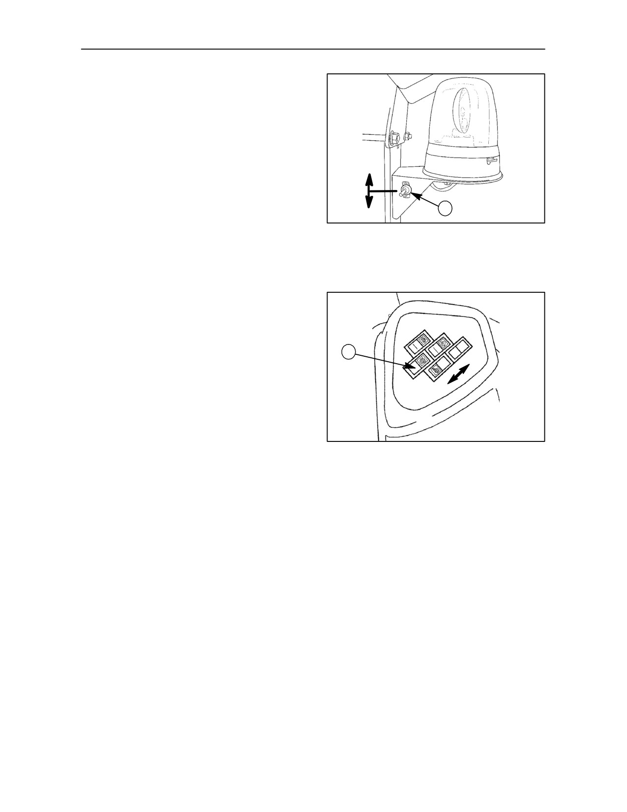
BEACON LAMP (WITHOUT CAB)-- Fig. 1
1. Beacon lamp ON/OFF button.
Position A:
ON
Position B:
OFF
A
1
B
TRE0020A
1
BEACON LAMP (WITH CAB)-- Fig. 2
1. Beacon lamp ON/OFF button.
Position A:
ON
1
B
Position B:
OFF
A
TRE0042B
2
7--2
SECTION 7 -- ACCESSORIES
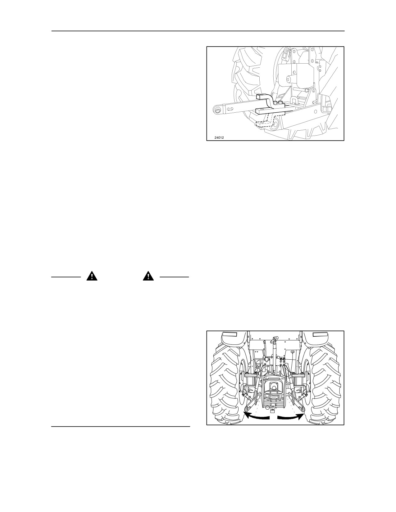
SWINGING DRAWBAR -- Figs. 3 and 4
Use the swinging drawbar for implements,
agricultural machinery and trailers with two axles.
Do not, on the other hand, use it for single--axle
trailers as they apply excessive weight to the bar,
which will risk tipping the tractor.
The wide horizontal trajectory of the bar is extremely
useful for implements and machines requiring lateral
freedom of movement, such as balers.
3
This equipment can be supplied:
--
with suitable brackets to fit either a rigid towing
hook or a Rockinger hitch;
--
with a bracket designed to fit only to a towbar.
The following adjustments can be made to the bar:
--
height adjustment, by turning the fork to face
upward or downward fig. 3;
--
prevention of lateral swing by inserting limiter
fork (1) fig. 4.
CAUTION
The towing equipment should be selected on the
basis of the type of trailer or implement to be towed
and should comply with current legislation.
--
The ease of handling and driving safety of the
tractor depends on correct towing adjustment.
--
A towing device fitted high up increases towing
capacity but also means that the tractor has a
tendency to tip back. Therefore ensure that the
trailer shaft is not at too great an upward angle.
--
When using four--wheel drive, the towing bracket
should be in its lower position with the shaft
almost horizontal.
--
Avoid towing excessively heavy trailers or loads.
--
Do not start suddenly as this considerably
increases the risk of tipping backwards.
TRE0852A
--
Always brake the trailer first and then the tractor.
4
7--3
SECTION 7 -- ACCESSORIES
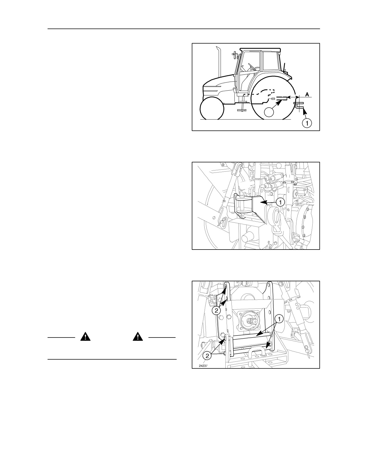
By carrying out the adjustments previously
described, the distance A of fork (1) on the swinging
draw--bar will be between
297
mm (11.69 in)
minimum and 455 mm (17.9 in) maximum from the
power take--off shaft (2).
To connect implements to the power take--off
correctly, fit the towing bracket facing downwards
2
fig. 3.
24269
5
HEIGHT ADJUSTABLE
RIGID HITCH -- Figs. 6 and 7
With rigid hitch (1) fig. 6 all types of trailer can be
towed, even those with only one axle.
The hitch can be set both above and below the power
take--off, with a total of six positions.
24238A
It can also be fitted with the towbar.
6
Fix the hitch to holes (2) fig. 7 using pins (1) fig. 7
WARNING
Use the front towing fork for possible emergency
trailer manoeuvres or for towing the tractor.
7
7--4
SECTION 7 -- ACCESSORIES
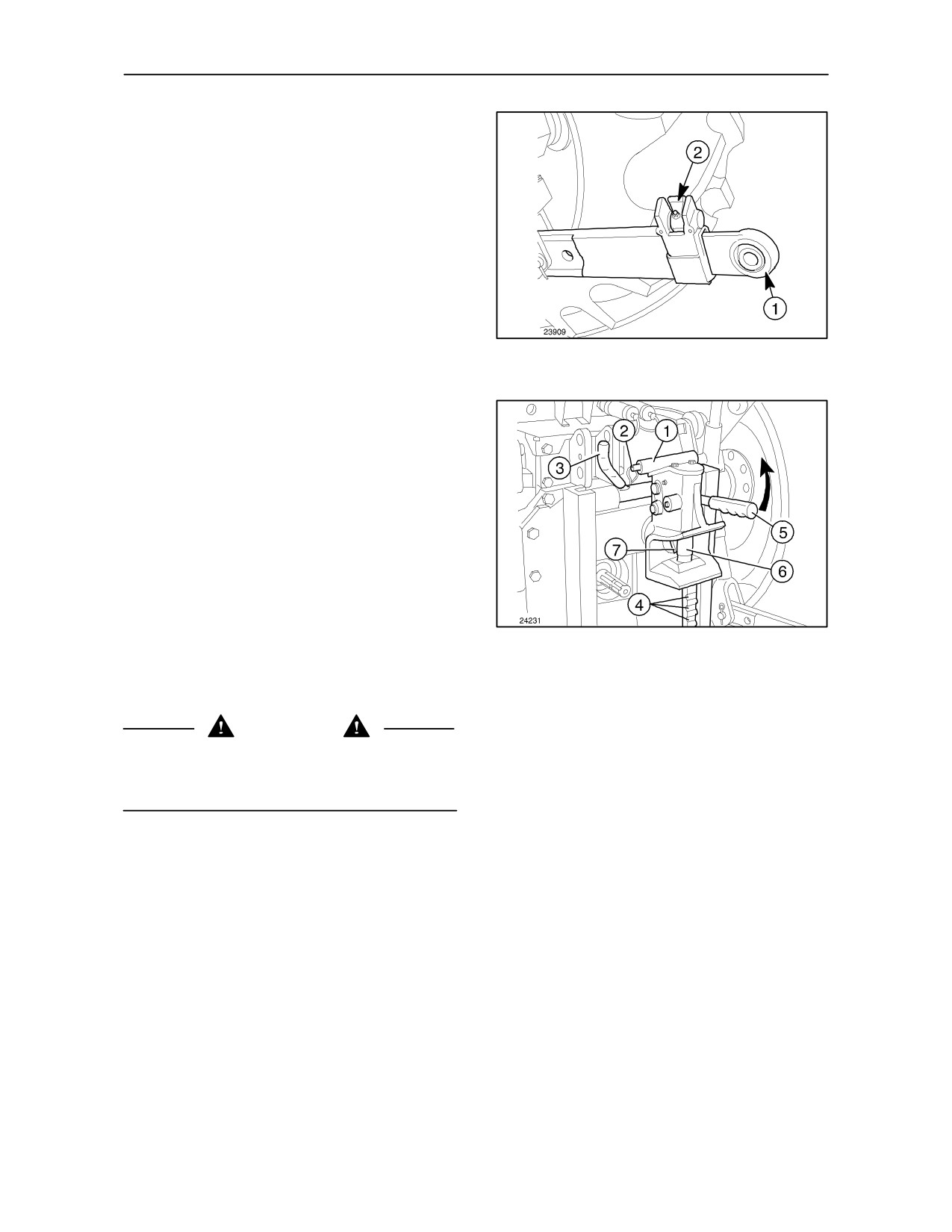
Lower link arms with telescopic ends
(optional) -- Fig. 8
To adjust, proceed as follows:
--
release the sliding ends (1) by turning retaining
blocks (2) inwards;
--
extract the ends (1) fig. 8 and connect to the
implement;
--
reverse the tractor: the telescopic ends slot into
their respective seatings and the retaining blocks
(2) snap shut automatically.
8
C CATEGORY HITCH (OPTIONAL) -- Fig. 9
This device is height--adjustable and can be fitted
with the towbar.
To adjust, proceed as follows:
--
with the right hand, grasp handle (1) and press
button (2);
--
with the left hand, pull handle (3) down to a
horizontal position to release the hitch and
position it at the desired height;
--
a few seconds before you reach the desired
9
height, press button (2) again, and push handle
(3) into a vertical position to allow the hitch to fit
firmly into one of the notches (4).
CAUTION
do not hitch the trailer with the hitch resting free on
the power take--off or on the lower check pins. The
hitch must always be firmly secured in the notches.
To hitch the trailer, proceed as follows:
--
push handle (5) upwards into a vertical position
to raise hitching pin (6);
--
get into the tractor, engage reverse gear, and
move back until lever (7) is engaged by the trailer
towing eye and hitching pin (6) is automatically
dropped into position;
When this has been done, lever (5) should be in a
horizontal position, and pin (6) inserted in the trailer
towing eye.
7--5
SECTION 7 -- ACCESSORIES
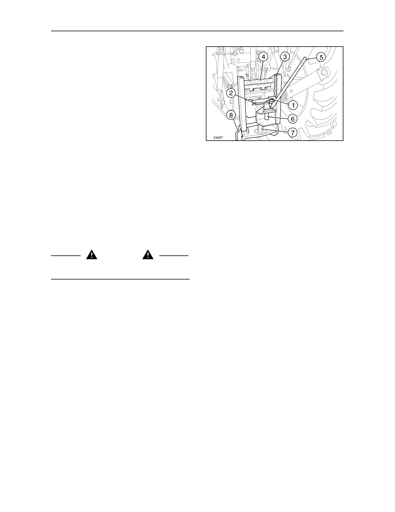
C CATEGORY HITCH (OPTIONAL)-- Fig. 10
This device is height--adjustable and can be fitted
with the towbar.
To adjust, proceed as follows:
--
unscrew safety pin (1);
--
pull handle (2) upwards and position the hitch at
the desired height;
--
fix it in one of the notches (3) by pushing handle
(2) down;
10
--
reinsert the safety pin and pull guard (4) down.
to remove hitching pin (6), pull rod (5) upwards and
unscrew.
HITCH FOR SEMI--TRAILERS (OPTIONAL)--
Fig. 10
Supplied together with the towing bar.
Semi--trailers are hitched to pin (7) fixed on the
towing bar bracket.
WARNING
after hitching the trailer to the pin, do no forget to fit
safety pin (8).
7--6
SECTION 7 -- ACCESSORIES
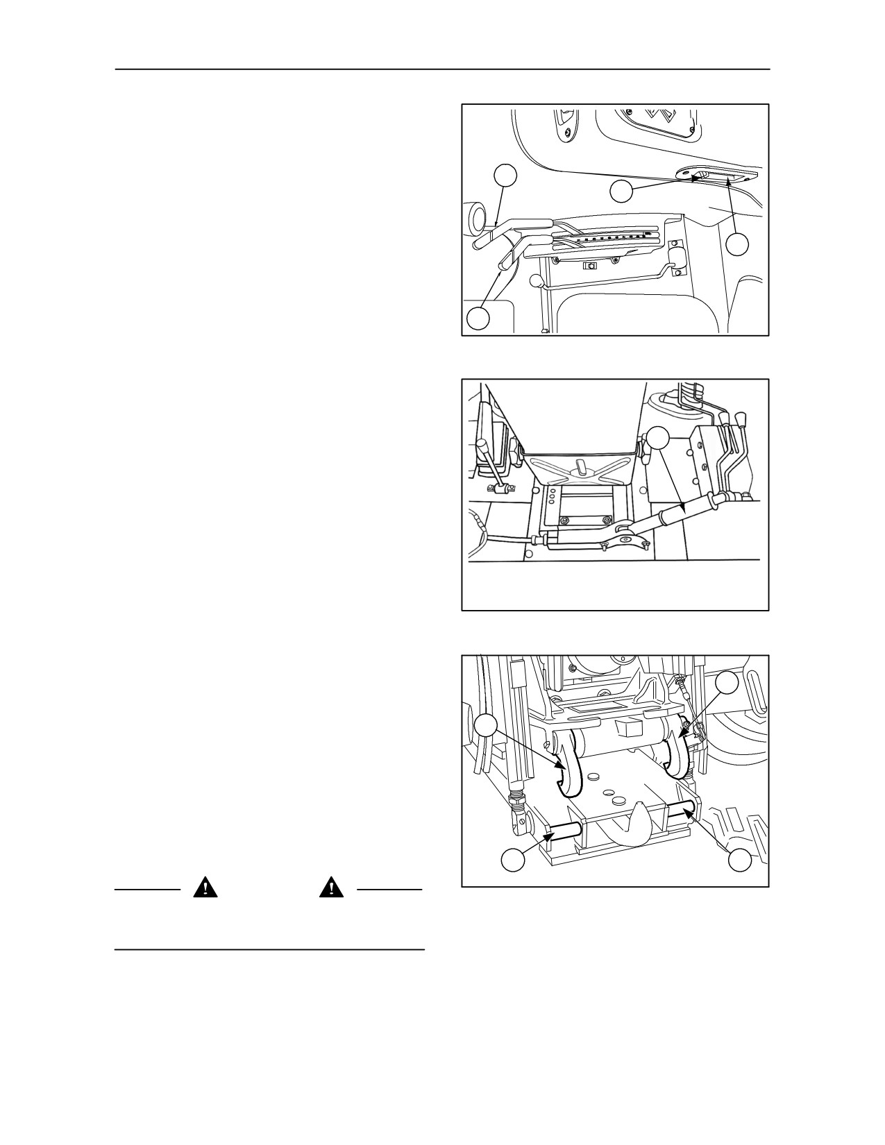
OPERATION OF AUTOMATIC PICK--UP
HITCH (not available in all markets)
This system makes it possible to tow trailers, imple-
3
ments and agricultural machinery with a ring type
4
drawbar. All hitching and unhitching operations can
be performed without leaving the driving seat.
1
Hitching
2
To lower the hook and couple the implement, pro-
ceed as follows:
11
--
remaining seated in the driving seat, move the
position control lever (3) fig. 11 fully rearward
and draft control lever (2) fig. 11 fully forward.
--
press the Lift--O--MaticTM button (1) fig. 11;
1
--
pull and hold the release lever (1) fig. 12 upwards
to disengage the locking hooks, at the same time
gradually move the position control lever (3)
fig. 11 forward until the hitch hook has lowered;
--
release the lever (1) fig. 12;
--
reverse the tractor and align the hitch hook under
the trailer drawbar ring;
TRE0901A
--
raise the hook by moving the position control
12
lever (3) fig. 11 slowly rearward; the hook will
engage the ring and the implement will be
automatically hitched as confirmed by the
1
audible click made by locking hooks (1) and (4)
fig. 13 on the pins (2) and (3);
4
--
when the implement is hitched, move the posi-
tion control lever (3) fig. 11 slightly forward so
that the weight of the hitch is supported by the
locking hooks (1) and (4) fig. 13;
--
press the Lift--O--MaticTM button (4) fig. 11 to
prevent inadvertent lowering of the hitch if the
lever (3) fig. 11 is moved accidentally.
3
2
MPB0396A
CAUTION
13
Before moving, check that the hooks (1) and (4)
fig. 13 are correctly locked on the pins (2) and (3).
7--7
SECTION 7 -- ACCESSORIES
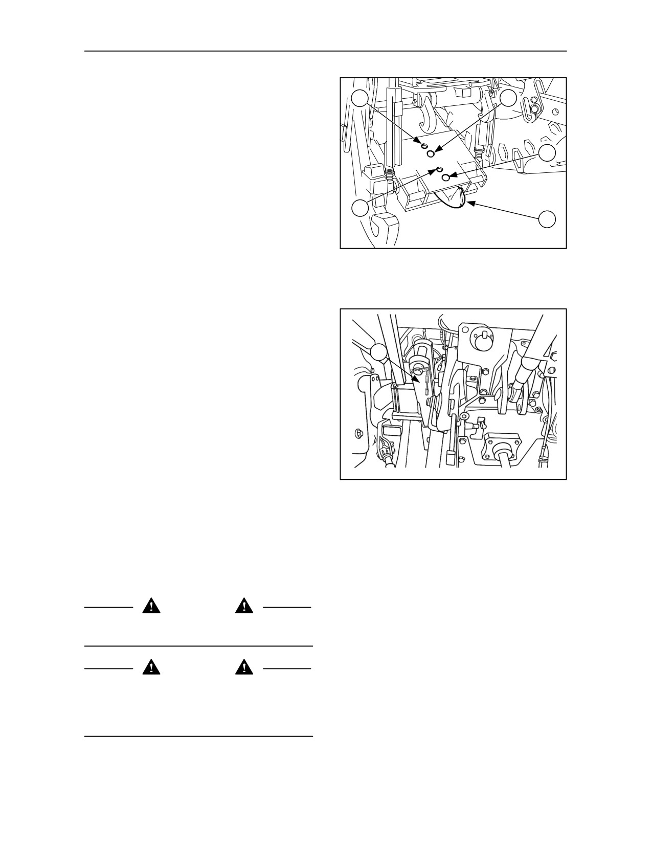
Unhitching
1
2
To unhitch the trailer or implement, proceed as fol-
lows:
--
position the tractor on flat, level ground;
3
--
press the Lift -- O -- MaticTM button (1) fig. 11;
--
move position control lever (3) fig. 11 fully rear-
ward to take the weight off the locking hooks (1)
and (4) fig. 13;
5
4
--
pull release lever (1) fig. 12 upward and gradual-
ly move the position control lever (3) fig. 11 for-
MPB0397A
ward to lower the hitch hook and implement to
14
the ground.
--
move tractor forward away from drawbar ring.
--
raise the hitch and lock into position before con-
tinuing with work.
1
To change from hitch hook mode to drawbar, pro-
ceed as follows:
--
remove drawbar (1) fig. 15 from its holder;
--
lower the pick--up hitch as previously described;
--
remove securing pins (2) and (3) fig. 14;
--
extract the hook (4) fig. 14, and refit the bar (1)
TRE0902A
fig. 15, reinserting the pins in their holes.
--
place hook in the storage holder.
15
In drawbar mode it is possible to have two different
distances from the PTO, by inserting the pins in holes
(1) and (5) or (2) and (3) fig. 14.
When towing equipment exerting high static down-
ward loads, such as two--wheeled trailers etc., al-
ways use the close--coupled drawbar position.
WARNING
Never raise or lower the pick--up hitch when in
drawbar mode with a trailer attached.
CAUTION
When supporting equipment on the drawbar or
pick--up hitch, ensure that the total weight on the rear
axle does not exceed the maximum static downward
load and rear tyre load capacity .
7--8
SECTION 7 -- ACCESSORIES
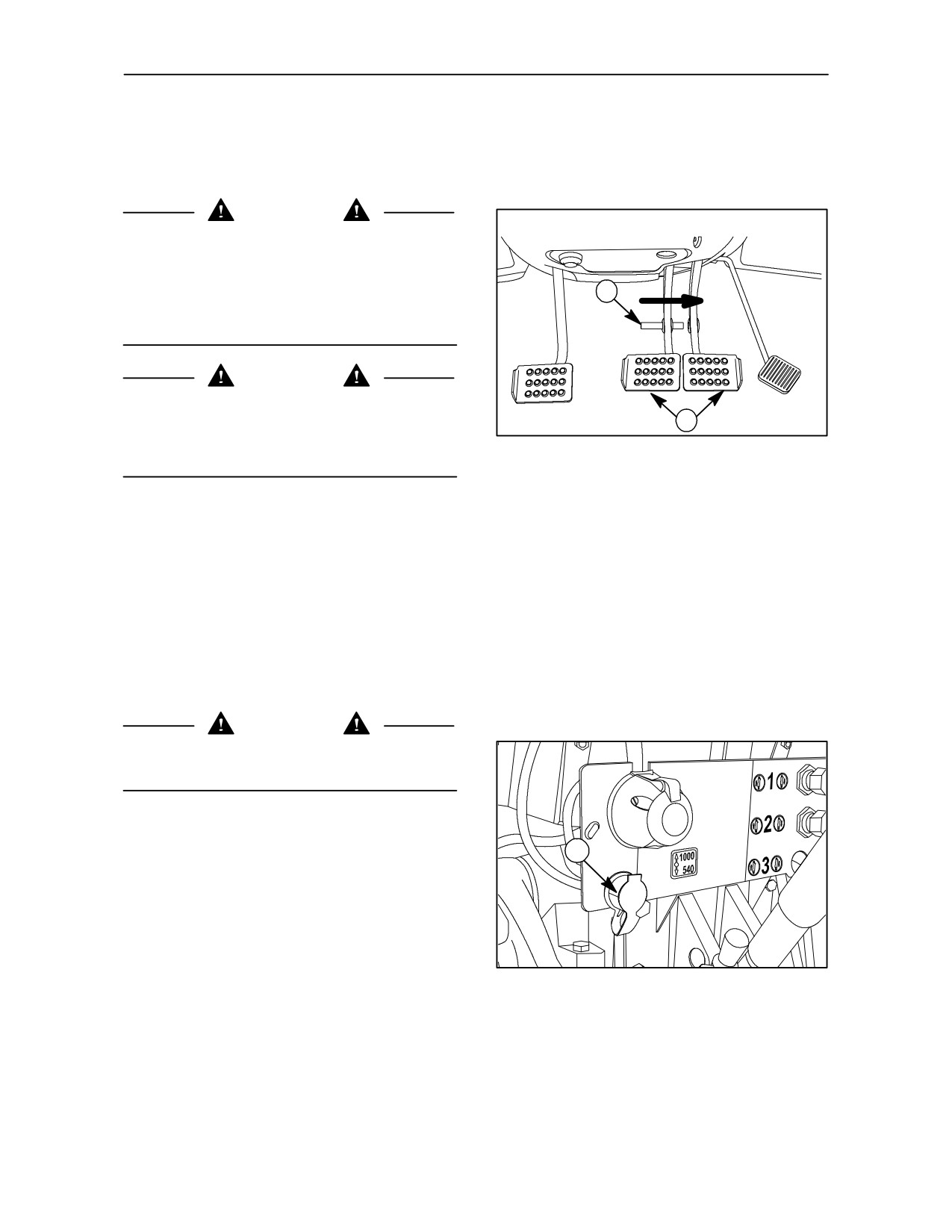
HYDRAULIC TRAILER BRAKE
(not available on all markets)
CAUTION
To use the hydraulic trailer braking system correctly,
follow the instructions below. In addition to the
correct operation of the braking system, following
these instructions will help you avoid dangerous
1
situations which can cause injuries or damage to
property.
DANGER
To brake both the tractor and the trailer
2
simultaneously, always connect the pedals together
with the locking pin (1) fig. 16, as required when
16
driving on roads.
The remote control valve for trailer hydraulic braking
is controlled by the tractor brakes hydrostatic circuit
oil, when pressurised by the relevant control pedals
(2). The trailer braking function uses the same oil as
the hydraulic lift circuit.
TRACTOR--TRAILER COUPLING
First hitch the trailer to the tractor towing bracket and
then, with the engine shut off, connect the trailer
brake line to coupler (1) fig. 17 on the tractor.
CAUTION
Before connecting the trailer, check that the
handbrake is applied and the tractor is in gear.
STARTING THE TRACTOR
1
Start the engine and press the brake pedals to re-
duce the time taken to release the trailer brake.
TRE0853A
17
7--9
SECTION 7 -- ACCESSORIES
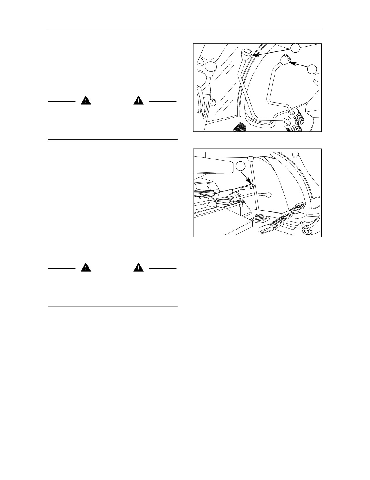
STOPPING THE TRACTOR
1
When the tractor is stopped with a trailer connected
and the engine running, move the gear shift lever (1)
2
and range lever (2) fig. 18 to neutral. At this point, pull
handbrake lever (1) fig. 19 to engage the trailer
parking brake.
DANGER
When the tractor is stationary, apply the handbrake
lever and wait for at least
10 seconds before
switching off the engine to ensure that the trailer
parking brake is engaged.
18
UNHITCHING A TRAILER FROM THE
TRACTOR
1
To disconnect the trailer from your tractor, proceed
as follows:
--
stop the tractor as previously described;
--
switch off the engine, as described above;
--
disconnect the trailer brake line from the tractor
coupler.
19
If the trailer is on a slope, place chocks behind the
wheels for greater safety.
CAUTION
If there should be any marked irregularity in the
operation of the braking system, contact your
authorised dealer immediately to have the problem
put right.
7--10
SECTION 7 -- ACCESSORIES
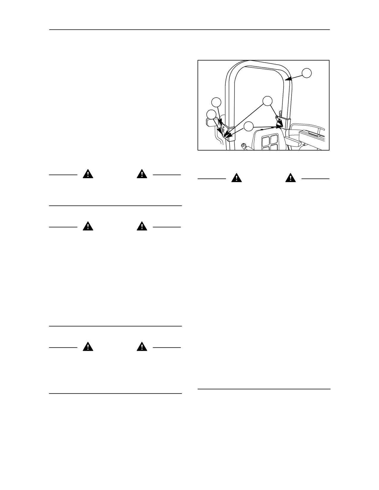
FOLDING ROLL BAR
The roll bar (optional) is of the folding type and can
be folded backwards when working in areas with
2
limited headroom.
To lower the roll bar, proceed as follows:
3
1
--
release securing pins (3) and extract the locking
pins (4) on both sides fig. 20;
5
--
fold the roll bar (2) fig. 20, backwards;
4
--
align holes (1) and (5), and insert the pins (4) to
TRE0823A
secure the roll bar in the lowered position.
20
WARNING
ATTENTION
When not working in areas with limited headroom,
always work with the roll bar raised, as shown in the
The roll bar (SAFETY DEVICE IN THE EVENT OF
figure.
OVERTURNING) is an integral part of the Structure
of the Tractor
The structure of the roll bar must in no way be
modified .
CAUTION
It is therefore prohibited to drill, weld or anyhow
connect any device to this safety member that would
impair its intended operation.
If used incorrectly, the tractor may overturn.
Any damage due to accident, fire, theft or corrosion
The roll bar may only be lowered when working in
to the original structure could make it inefficient and
areas with limited headroom.
lessen its safety.
It is therefore necessary for specialized personnel to
With the roll bar lowered the driver is unprotected,
evaluate the damage and, if necessary, have the
therefore it is essential that the roll bar is raised after
damaged parts replaced
working in areas with limited headroom.
--
The roll bar must be replaced in the event of
When the roll bar is raised, always use the seat belt.
overturning.
Do not use the seat belt when the roll bar is lowered.
--
All the safety parts, such as the operator’s seat,
including any seat belts, must be carefully
checked and must show no sign of any damage
whatsoever.
CAUTION
--
All damaged parts must be replaced.
Do not attach chains or cables to the roll bar as this
IN THE EVENT OF OVERTURNING, DO NOT
may cause the tractor to tip backwards.
ATTEMPT TO REPAIR, WELD OR STRAIGHTEN
THE ROLL BAR, contact your Dealer’s
Only tow using the specific devices provided on the
specialized personnel instead
tractor.
7--11
SECTION 8
SPECIFICATIONS
The specifications on the following pages are given for your information and guidance. For further information
concerning the tractor, please consult your authorised dealer.
8--1
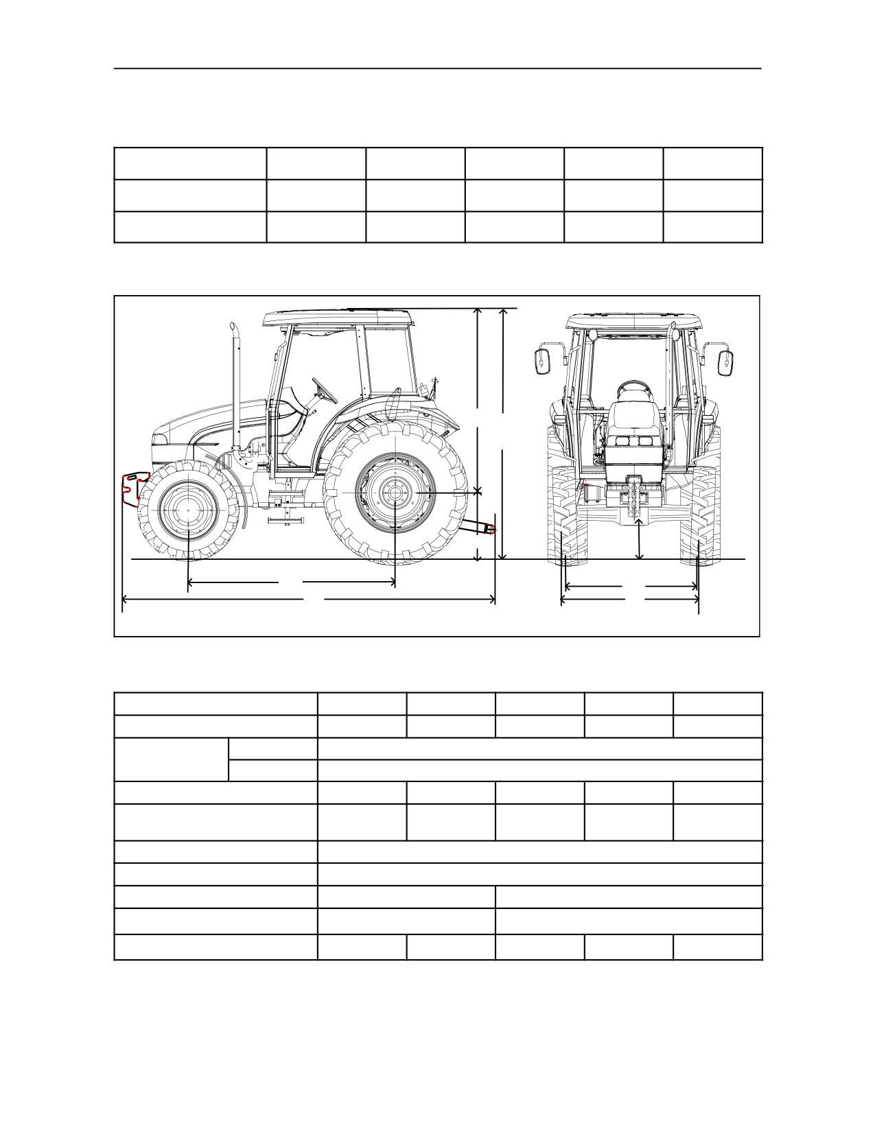
SECTION 8 -- SPECIFICATIONS
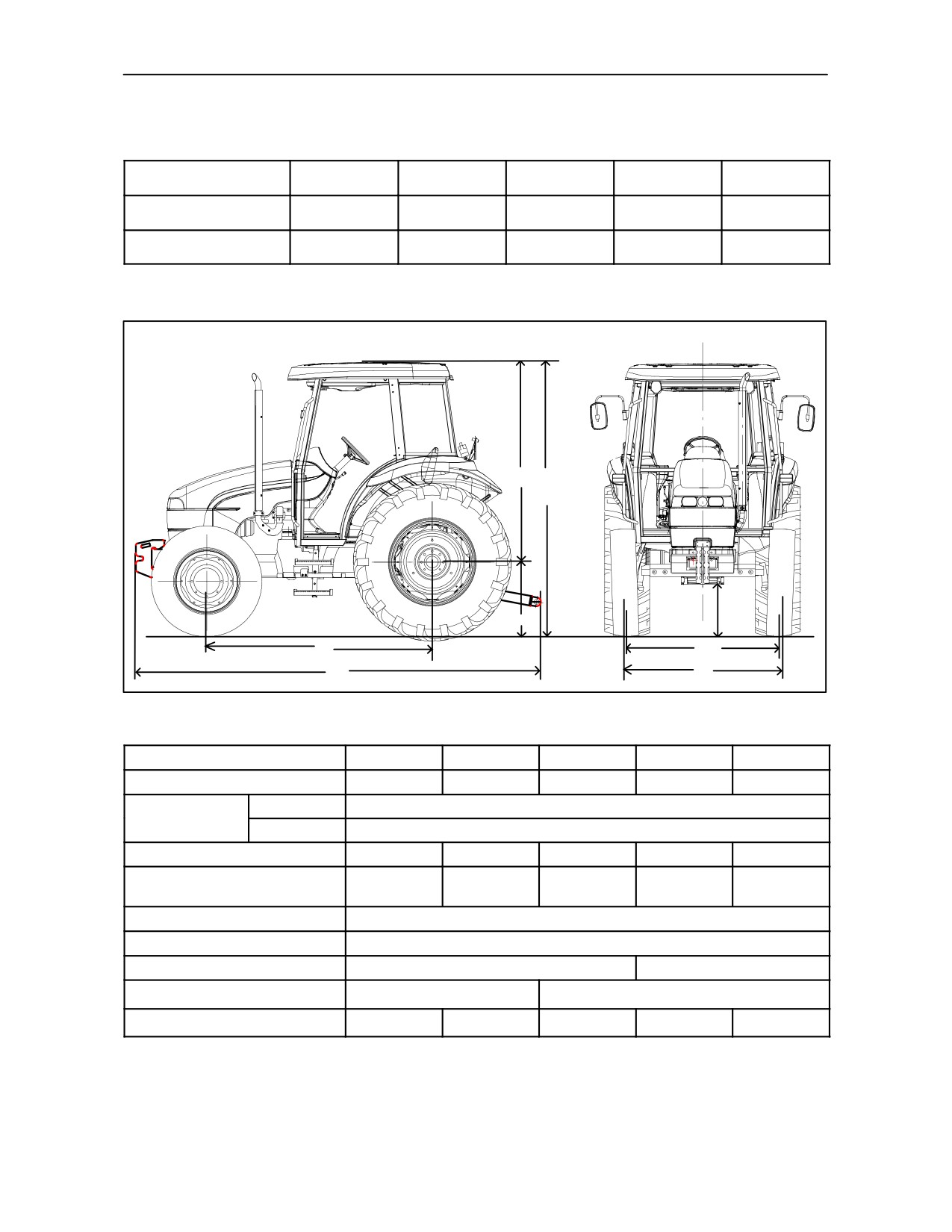
DIMENSIONS OF 2WD MODELS WITH STANDARD TYRES
Tyre Combinations
TD 60D
TD 70D
TD 80D
TD 90D
TD 95D
FRONT
7.50--16
7.50--16
7.50--16
7.50--18
7.50--18
REAR
14.9/13--30
14.9/13--30
16.9/14--30
18.4/15--30
18.4/15--34
A D
E
H
Rs
TRE0085A
TRE0032A
B
F
C
G
1
Dimensions mm (in)
TD 60D
TD 70D
TD 80D
TD 90D
TD 95D
Tyre radius under load (Rs)
665
(26.13)
665
(26.13)
695
(27.31)
720
(28.30)
770
(30.30)
Cab
1878
(73.81)
A
ROPS
1896
(74.51)
B
2175
(85.48)
2175
(85.48)
2305
(90.59)
2305
(90.59)
2388
(93.85)
3918
3918
4032
4032
4115
C
(153.98)
(153.98)
(158.46)
(158.46)
(161.72)
D (Cab)
Acab + Rs
E (ROPS)
Arops + Rs
F (front)
1400--1900 (55--75)
1410 --1910 (56--75)
G (rear)
1425--1925 (56--76)
1420--2025 (56--80)
H
275
(10.83)
275
(10.83)
285
(11.22)
346
(13.62)
390
(15.35)
8--2
SECTION 8 -- SPECIFICATIONS
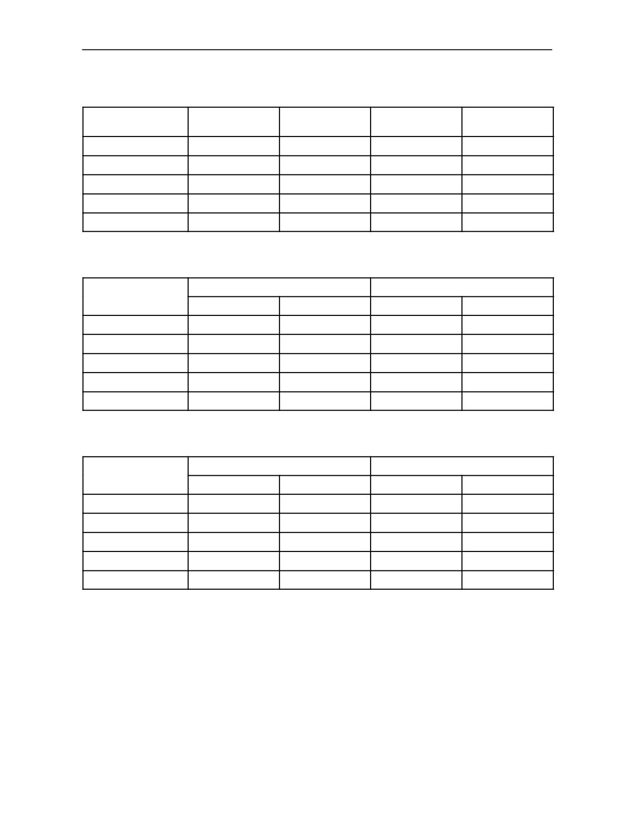
DIMENSIONS OF 4WD MODELS WITH STANDARD TYRES
Tyre Combinations
TD 60D
TD 70D
TD 80D
TD 90D
TD 95D
FRONT
9.50--24
9.50--24
11.2--24
12.4--24
12.4--24
REAR
14.9/13--30
14.9/13--30
16.9/14--30
18.4/15--30
18.4/15--34
A
D
E
H
Rs
TRE0085A
TRE0032A
B
F
C
G
2
Dimensions mm (in)
TD 60D
TD 70D
TD 80D
TD 90D
TD 95D
Tyre radius under load (Rs)
665
(26.13)
665
(26.13)
695
(27.31)
720
(28.30)
770
(30.30)
Cab
1878
(73.81)
A
ROPS
1896
(74.51)
B
2119
(83.28)
2119
(83.28)
2249
(88.39)
2249
(88.39)
2332
(91.65)
3862
3862
3976
3976
4059
C
(151.78)
(151.78)
(156.26)
(156.26)
(159.52)
D (Cab)
Acab + Rs
E (ROPS)
Arops + Rs
F (front)
1450--1880 (57--74)
1550--1980 (61--78)
G (rear)
1425--1925 (56--76)
1420--2025 (56--80)
H
265
(10.43)
265
(10.43)
292
(11.50)
333
(13.11)
375
(14.76)
8--3
SECTION 8 -- SPECIFICATIONS
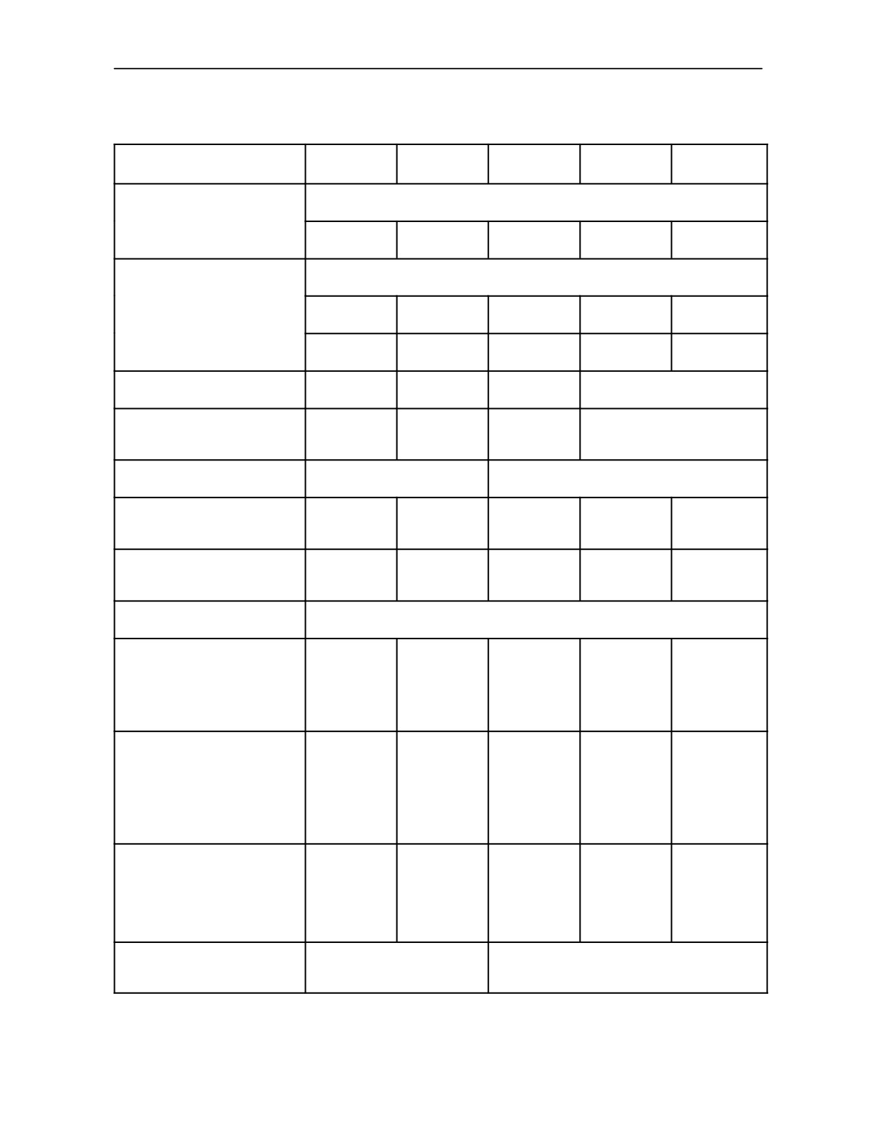
WEIGHTS (kg)
Front end
Rear wheel
MODELS
Front support
TOTAL
weights
weights
TD 60D
80
4x40: 160
4x50:200
440
TD 70D
80
4x40: 160
4x50:200
440
TD 80D
80
6x40: 240
6x50: 300
620
TD 90D
80
8x40: 320
6x50: 300
700
TD 95D
80
10x40: 400
6x50: 300
780
TRACTOR WEIGHT WITH ROPS
without weights
with weights
MODELS
2WD
4WD
2WD
4WD
TD 60D
2650
2920
3090
3360
TD 70D
2650
2920
3090
3360
TD 80D
2940
3420
3560
4040
TD 90D
2940
3420
3640
4120
TD 95D
3150
3580
3930
4360
TRACTOR WEIGHT WITH CAB
without weights
with weights
MODELS
2WD
4WD
2WD
4WD
TD 60D
2840
3080
3280
3520
TD 70D
2840
3080
3280
3520
TD 80D
3170
3600
3790
4220
TD 90D
3170
3600
3870
4300
TD 95D
3340
3770
4120
4550
8--4
SECTION 8 -- SPECIFICATIONS
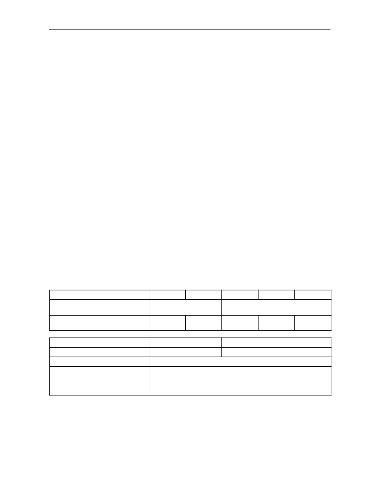
ENGINE SPECIFICATION
Model
TD 60D
TD 70D
TD 80D
TD 90D
TD 95D
IVECO or TTF
Engine type
8035.05D.939
8035.25C.939
8045.05R.939
8045.25.939
8045.25L.939
BOSCH Injection pump
4--stroke diesel, direct injection
-- for IVECO engine
L976
L977
L985
L982
L952
-- for TTF engine
L--1068--1
L--1068--2
L--1068--3
L--1068--4
L--1068
Naturally aspirated
YES
NO
YES
NO
MITSUBISHI
Turbocharged
NO
NO
MITSUBISHI--GARRET
--GARRET
Number of cylinders
3
4
Bore and stroke
mm
104 x 115
104 x 115
104 x 115
104 x 115
104 x 115
(in)
(4.1 x 4.5)
(4.1 x 4.5)
(4.1 x 4.5)
(4.1 x 4.5)
(4.1 x 4.5)
Total displacement
cm3
2931
2931
3908
3908
3908
(cubic in)
178.85
178.85
238.47
238.47
238.47
Compression ratio
18±0.5:1
Engine max. power 2000/25 EC
IVECO:
kW/rev/min
43.4/2500
50,7/2500
58.8/2500
65.5/2500
69.1/2500
HP(CV)/rev/min
59.0/2500
69.0/2500
80.0/2500
89.0/2500
94.0/2500
Engine max. power
ECE R120 (ISO 14396)
TTF:
kW/rev/min
43.5/2500
50.7/2500
58.8/2500
65.5/2500
72.0/2500
HP(CV)/rev/min
59.0/2500
69.0/2500
80.0/2500
89.0/2500
98.0/2500
Maximum torque Nm /
rev/min
IVECO:
206 / 1500
255 / 1500
274 / 1500
317 / 1500
346 / 1500
TTF:
205 / 1500
260 / 1500
270 / 1500
340 / 1500
360 / 1500
Dynamic equalizer
N/A
YES
with counter--rotating weights
8--5
SECTION 8 -- SPECIFICATIONS
TIMING
With overhead valves
Timing data
Inlet :
-- start before TDC
12o
-- end after BDC
31o
Exhaust :
-- start before TDC
50o
-- end after BDC
16o
Valve clearance, engine cold :
-- inlet and exhaust
mm (in)
0.30
± 0.05 (0.0118 ± 0.002)
FUEL SYSTEM
Double--diaphragm fuel pump on injection pump supply line.
Rotary injection pump with centrifugal speed governor operating at all speeds and incorporating automatic
advance BOSCH VE--type.
Fuel filtration :
--
mesh filter in the fuel pump;
--
replaceable cartridge filter in the injection pump
feed line with water separator.
Fuel sediment filter (optional).
Double cartridge dry air filter, with centrifugal pre--filter and automatic dust extractor.
Optional : air filter with self--cleaning device (Donaspin).
MODEL
TD 60D
TD 70D
TD 80D
TD 90D
TD 95D
Engine injection pump, number of
orifices :
3
4
Before TDC of cylinder No. 1 on
compression stroke (°) :
4±0.5
0±0.5
4±0.5
1±0.5
0±0.5
Injectors :
3 cyl.
4 cyl.
-- firing order :
1--2--3
1--3--4--2
-- number of injection nozzles :
5
-- calibration :
bar
260--272
(Psi)
(3770 to 3945)
kg/cm2
265--277
8--6
SECTION 8 -- SPECIFICATIONS
LUBRICATION
Pressurised, by gear pump. Oil filtration : pressurised through pump intake mesh and replacable cartridge filter
on engine intake.
Lubrication pressure with engine hot and at max. speed
On TD60D, TD70D, TD80D and TD90D models:
-- IVECO engine
2.9 -- 3.9 bar (42.06 -- 56.57 Psi) (3 -- 4 kg/cm2);
-- TTF engine
2.5 -- 3.5 bar (36.26 -- 50.76 Psi) (2.55 -- 3.57 kg/cm2).
On TD95D model:
-- IVECO engine
5.0--6.0 bar (72.534--87.0408 Psi) (5.1--6.1 kg/cm2);
-- TTF engine
4.0--5.0 bar (58.02--72.52 Psi) (4.08--5.99 kg/cm2).
Engine oil cooled by a heat exchanger using engine coolant (On TD95D engine).
COOLING SYSTEM
Water, pressurised circulation by centrifugal pump.
Radiator with 3 lines of vertical copper pipes for TD 60D, TD 70D, TD 80D and TD 90D models, or 4 lines of
vertical copper pipes for TD 95D model.
Cooling fan fitted on same shaft as water pump.
Water circulation from engine to radiator thermostatically controlled.
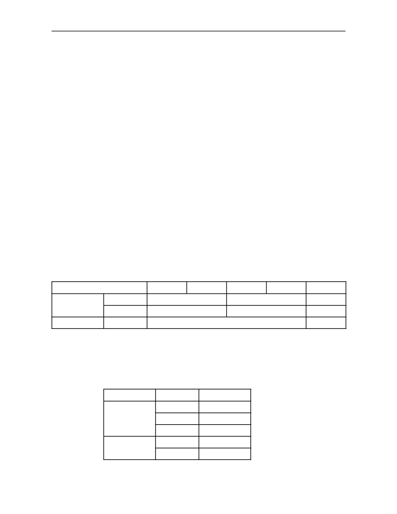
TRANSMISSION
Clutch
Dry double--plate, with separate controls : pedal operation for gearbox and hand lever for power take--off.
Disk material and diameter (inches):
MODELS
TD 60D
TD 70D
TD 80D
TD 90D
TD 95D
Organic
11”
--
--
Engine
Cerametallic
--
11”
12”
PTO
Organic
11”
12”
GEARS
Permanently engaged helical mesh with 4 gear ratios.
Full syncromesh for all gears.
Range gear cascade connection with three forward gear ranges and one reverse gear range.
Speed
Gearbox
Model
12x4
Opt.
30 km/h
12x12
Std.
20x12
Opt.
12x12
Opt.
40 km/h
20x12
Opt.
8--7
SECTION 8 -- SPECIFICATIONS
REAR TRANSMISSION
30 km/h -- 2WD
30 km/h -- 4WD
40 km/h -- 4WD
Bevel
-gear ratio
9/43
9/43
11/43
Differential with pedal controlled locking device and automatic release.
Final drive : Pinion -- gear type
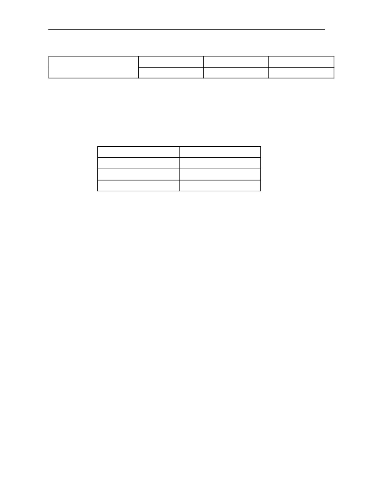
POWER TAKE--OFF (PTO)
Fully independent, in three versions : 540 rpm; 540, 750 and 1000 rev/min; (540 and
1000
rev/min not for all
markets). With engine running at :
PTO (rev/min)
Engine (rev/min)
540
2200
750
(540 Economy)
2380
(1715)
1000
2380
Ground speed PTO (see page 3--8).
Manual control : clutch control lever, take--off engage lever and speed selector lever.
Direction of rotation, viewed from rear of tractor : clockwise.
HYDRAULIC LIFT
Operates in the following modes :
--
draft control;
--
position control;
--
mixed control;
--
float mode.
Draft control is through the link arms by means of a torsion bar.
The link--arms are raised and lowered using a pushbutton--operated device Lift--O--MaticTM.
Oil supply is from the transmission by gear pump operated directly by the engine :
type
C 31
--
pump speed with engine at maximum power (rev/min):
2328
--
corresponding nominal flow: dm3/min / l/min (US. gal/min):
40.1
(10.8)
--
corresponding nominal flow (Mega Flow Pump*): dm3/min / l/min (US. gal/min):
51.7
(13.6)
--
pressure relief valve calibration : bar
(Psi)
190
(2755)
(kg/cm2)
194
* Optional
8--8

SECTION 8 -- SPECIFICATIONS
Maximum lift capacity
With lift rods located in rear holes of horizontal arms and upper hole of top link attachment bracket :
Model
TD 60D
TD 70D
TD 80D
TD 90D
TD 95D
at link ends of horizontal arms
3000
3565
(kg)
with center of gravity at 610 mm
2260
2700
(24 in) from link ends (kg)
THREE--POINT LINKAGE
Category I and Category II three--point linkage device.
Stabilizer device :
--
telescopic stabilizers (standard).
Single or double--acting rear remote control valves: up to three, one with float and automatic release.
FRONT AXLE
Central pivoting, telescopic, inverted ”U” structure.
Track adjustment : by extending the axle.
FRONT WHEELS 2WD
Rims with integral steel wheel discs.
FRONT WHEELS 4WD
Wheels in two parts : steel wheel disc and rim.
Track adjustment : by interchanging rims to discs and to wheel hubs.
REAR WHEELS
Wheels in two parts : steel wheel disc and rim.
Track adjustment : by interchanging rims to discs and to wheel hubs.
NOTE: Tyre specifications are shown on pages
between 3--41 and 3--54.
8--9
SECTION 8 -- SPECIFICATIONS
STEERING
Hydrostatic control, independent circuit.
Metalic cartridge oil filter, fitted in oil reservoir.
Gear pump operated directly by the engine :
--
pump type :
C25*RP
--
pump speed with engine at max. power : rev/min
2328
--
corresponding flow : dm3/min / l/min (gal/min)
26.5
(5.8)
--
pressure relief valve calibration :
All 2WD models: 100 bar (1450 Psi, 102 kg/cm2)
. . . . . . . . . . . . . . . . . . . . . . . . . . . . All 4WD models: 125 bar (1813 Psi, 127 kg/cm2)
--
minimum turning radius, two--wheel drive models : without brakes
. . . . . . . . . . . . . . . . . . . . . . . . . . . . TD 60D, TD 70D models : 3.8 m (12.5 ft)
. . . . . . . . . . . . . . . . . . . . . . . . . . . . TD 80D, TD 90D and TD 95D models : 3.9 m (12.8 ft)
4WD FRONT AXLE
Central pivoting axle and co--axial transmission shaft on the longitudinal axis of the tractor. No universal joints
on transmission shaft. Differential with two planetary pinions.
Bevel gear pair ratios :
--
model TD 60D and TD 70D :
9/38
--
model TD 80D, TD 90D and TD 95D :
9/39
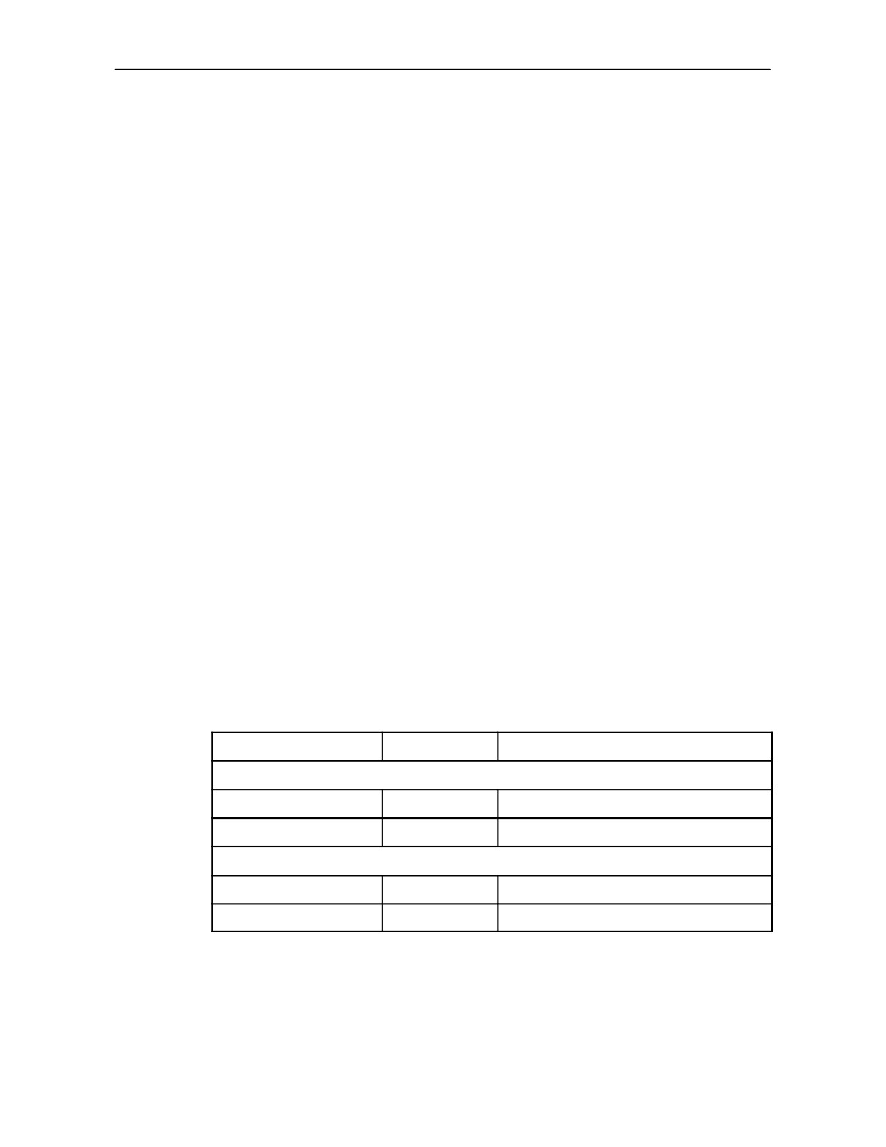
Minimum turning radius (m):
TD 60D, TD 70D
TD 80D, TD 90D, TD 95D
4WD engaged
brake assisted
3.6
4.1
without brakes
5.3
5.6
4WD disengaged
brake assisted
4.2
4.5
without brakes
4.9
5.1
8--10
SECTION 8 -- SPECIFICATIONS
BRAKES
Rear service brakes
Oil--immersed disc brakes, fitted on differential axle shafts.
Mechanically operated with independent hydraulic circuits for right and left--hand brakes, operated by separate
pedals.
Pedals are connected for simultaneous braking when driving on roads.
Front service brakes
Disc brake, hydrostatically controlled (not available at all markets), mounted on front final drive.
Pedals are connected for simultaneous braking.
Parking brake on transmission
Disk brake, fully independent, mounted beneath gearbox and connected to pinion shaft. Mechanically operated
by hand lever.
BODYWORK AND DRIVING POSITION
--
With ROPS
Platform, instrument console and mudguards form a single, modular structure, suspended on 4 rubber blocks.
Pre--lined sheet metal mudguards with partially shaped galvanised layer.
Mounting structure for roll bar.
Fuel tank located on left--hand side under the platform.
Hood hinged at rear and held open by gas strut.
--
With Cab
Mudguards and cab form a single integrated structure. Fuel tank located on left--hand side under the cab module.
Hood hinged at rear and held open by gas strut.
Seat
Padded, with parallelogram suspension, adjustable springing and position.
TOWING DEVICES
--
Rear swinging drawbar.
--
Rear height--adjustable rigid hook.
--
Front pull--type hook.
8--11
SECTION 8 -- SPECIFICATIONS
ELECTRICAL SYSTEM
Voltage
12 V
Alternator
--
65 A for models TD60D, DT70D, TD80D and TD90D. 85A for model TD95D.
--
Max. power with engine running at 2500 rpm -- approximately; 540W
--
Integral electronic voltage regulator.
Battery
105 Ah (w/o cab) and 120 Ah (w/cab).
Starter motor
2.5 kW for TD 60D and TD 70D models
3.5 kW for TD 80D, TD 90D and TD 95D models.
Lights
Two asymmetrical front headlamps using 55 W bulbs (white or yellow).
Two front light clusters including :
--
side lights (5 W bulb) with white transparent cover;
--
direction indicator (21 W bulb) with amber transparent cover.
Two rear light clusters including :
--
side lights (5 W bulb) with red transparent cover;
--
direction indicator (21 W bulb) with amber transparent cover;
--
brake (stop) light (21 W bulb) with red transparent cover;
--
number plate light, 5 W.
Red rear reflectors.
8--12
SECTION 8 -- SPECIFICATIONS
Instruments and accessories
--
Multi--function instrument panel
--
7--pin DIN power socket
--
Thermostart
--
Flashing hazard warning light indicator for tractor and trailer.
--
Work lamps (55 W bulb)
--
Beacon 55 W.
NOTE: Under the EC regulations, the maximum permissible overall width for tractors equipped with standard
tail--lights is 2150 mm. With wheels set at maximum track width, the maximum overall width obtainable is 2315
mm for machines with ROPS, and 2510 mm for machines with cab. If these wider settings are adopted, the
tail--lights must be mounted to special extendible arms (available on request) so that they can be adjusted to
indicate the overall width of the tractor.
8--13

SECTION 9 -- 1ST 50 HOUR SERVICE SHEETS
INSPECTIONS AND/OR OPERATIONS TO BE CARRIED OUT -- Dealer’s Copy
NON FUNCTIONAL INSPECTIONS/OPERATIONS
OPERATIONAL INSPECTIONS
1. Tyre pressures and condition
1. Lights and internal instrumentation
2. Oil and liquid leaks
2.
Air filter cartridge and hoses
3. Maximum and minimum idling speeds
3. Cooling system hoses
and engine cut--off
4.
Specific gravity and level of coolant
4. Power take--off and brakes
(specific gravity 1,071 to 1,083 at 16o C) . . .
5. Hydraulic system:
5.
Replace fuel filter, clean sediment filter
Draft control working
Position control working
and purge air from fuel system
Auxiliary control valves
6.
Drive belts for cooling fan, alternator and
Control valves intake
air conditioning compressor
System pressure
7.
Change engine oil and filter
8.
Change hydraulic oil filter
FUNCTIONAL INSPECTIONS
9.
Check oil level in rear transmission housing
1. Engine, accelerator and speed governor . . .
10. Grease all lubrication fittings and
2. Gearbox
lubricate joints
3. Steering operates correctly
4. Differential lock and 4WD engage/disengage
11. Tighten wheel disc nuts
5. Brake operation
12. Tighten wheel rim nuts
6. Optional equipment and accessories
13. Tighten bolts on front ballast
14. Front wheel toe--in and steering stops
INSPECTIONS OF SAFETY EQUIPMENT
15. Battery leads and relative fittings
16. Windscreen wiper, washer bottle level
1. Safety belts (optional)
2. Torque cab mounting nuts
17. Cab air filter clean
3. Power take--off electrical safety
18. Seat operation
devices engaged
19. Exhaust pipe mounting
4. Handbrake operation and adjustment
40 Nm (4,1 kgm) (29.7 ft.lbs)
5. Safety guards and covers
Inspections and operations carried out
Tractor model
Serial No.:
Customer’s signature
Date
Dealer’s signature
Date
9--1
SECTION 9 -- 1ST 50 HOUR SERVICE SHEETS
INSPECTIONS AND/OR OPERATIONS TO BE CARRIED OUT -- Owner’s Copy
NON FUNCTIONAL INSPECTIONS/OPERATIONS
OPERATIONAL INSPECTIONS
1. Tyre pressures and condition
1. Lights and internal instrumentation
2. Oil and liquid leaks
2.
Air filter cartridge and hoses
3. Maximum and minimum idling speeds
3. Cooling system hoses
and engine cut--off
4.
Specific gravity and level of coolant
4. Power take--off and brakes
(specific gravity 1,071 to 1,083 at 16o C) . . .
5. Hydraulic system:
5.
Replace fuel filter, clean sediment filter
Draft control working
Position control working
and purge air from fuel system
Auxiliary control valves
6.
Drive belts for cooling fan, alternator and
Control valves intake
air conditioning compressor
System pressure
7.
Change engine oil and filter
8.
Change hydraulic oil filter
FUNCTIONAL INSPECTIONS
9.
Check oil level in rear transmission housing
1. Engine, accelerator and speed governor . . .
10. Grease all lubrication fittings and
2. Gearbox
lubricate joints
3. Steering operates correctly
4. Differential lock and 4WD engage/disengage
11. Tighten wheel disc nuts
5. Brake operation
12. Tighten wheel rim nuts
6. Optional equipment and accessories
13. Tighten bolts on front ballast
14. Front wheel toe--in and steering stops
INSPECTIONS OF SAFETY EQUIPMENT
15. Battery leads and relative fittings
16. Windscreen wiper, washer bottle level
1. Safety belts (optional)
2. Torque cab mounting nuts
17. Cab air filter clean
3. Power take--off electrical safety
18. Seat operation
devices engaged
19. Exhaust pipe mounting
4. Handbrake operation and adjustment
40 Nm (4,1 kgm) (29.7 ft.lbs)
5. Safety guards and covers
Inspections and operations carried out
Tractor model
Serial No.:
Customer’s signature
Date
Dealer’s signature
Date
9--3