New Holland Workmaster 25, Tier 4B (final) Compact Tractor. OPERATOR’S MANUAL (2020) - page 4
7 - MAINTENANCE
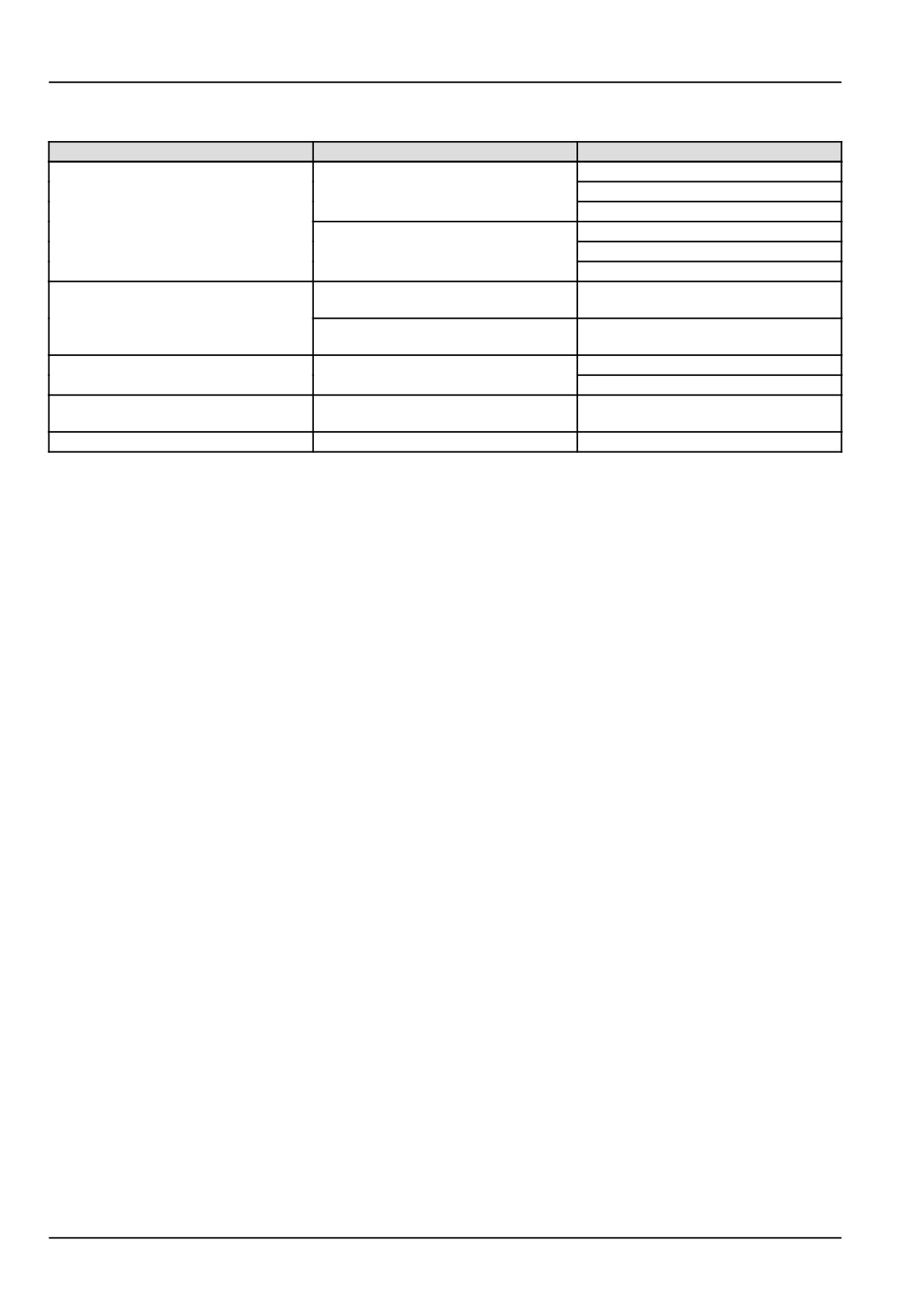
Consumables
Lubricant
Type and Description
Container Size
0.946 l (1 US qt)
SAE 10W-30 CF-4 ENGINE OIL
3.785 l (1 US gal)
18.93 l (5 US gal)
Engine Oil
0.946 l (1 US qt)
SAE 15W-40 CF-4/SG ENGINE OIL
3.785 l (1 US gal)
18.93 l (5 US gal)
HYDRAULIC TRANSMISSION OIL -
18.93 l (5 US gal)
PREMIUM
Transmission/Hydraulic Oil
MULTI-SEASON HYDRAULIC
18.93 l (5 US gal)
TRANSMISSION OIL SAE 0W-20
HYPOID GEAR OIL EXTREME PRESSURE
0.946 l (1 US qt)
Front Axle/Gear Oil
80W-90
9.46 l (2.5 US gal)
MULTI-PURPOSE GREASE EXTREME
Grease
Tube 14 oz
PRESSURE AND ANTI-WEAR NLGI 2
Coolant
IAT COOLANT 11 - CLASSIC
3.785 l (1 US gal)
7-6
7 - MAINTENANCE
Engine cooling system - Basic instructions
Definition
Organic Acid Technology (OAT) coolant
A coolant that relies on inhibitors such as organic acid salts for corrosion and cavitation protection.
NOTICE: You should not mix OAT coolant with conventional coolant. Mixing OAT coolant with conventional coolant
will reduce the effectiveness of OAT coolant.
NOTE: If you need to change a machine from conventional coolant to OAT coolant or vice versa, you should follow
the “Changing coolant types” procedure below to attain the full benefit of the coolant.
Changing coolant types
To change coolant from OAT coolant to conventional
coolant (or vice versa)
1. Empty the engine cooling system by draining the
coolant into a suitable container.
2. Fill the system with clean water.
3. Start the engine and run for at least 30 min.
4. Repeat Steps 1 to 3, for a total of two washes.
5. Fill the system with conventional coolant
(or OAT
coolant).
6. Operate the engine until it is warm. Inspect the ma-
chine for leaks.
7-7
7 - MAINTENANCE
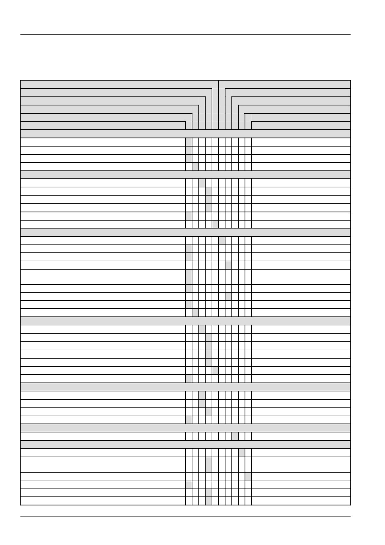
Maintenance planning
Maintenance chart
Tighten
Grease
Replace
Adjust
Change fluid
Drain fluid
Cleaning
Bleed
Check
Test
Maintenance action
Page no.
Every 8 hours or daily
Engine lubrication system - Check
x
7-9
Engine cooling system - Check
x
7-10
Transmission - Check
x
7-12
Radiator screen cleaning
x
7-13
After first 50 hours
Engine lubrication system - Change fluid
x
7-14
Fuel filters - Replace
x
7-15
Hydraulic oil suction filter - Replace
x
7-16
Hydrostatic Transmission (HST) oil filter - Replace
x
7-17
Roll Over Protective Structure (ROPS) frame - Check
x
7-18
Wheel hardware - Check
x
7-19
Every 50 hours
Machine fittings - Grease
x
7-20
Transmission - Check
x
7-12
Tire pressure - Check
x
7-23
Clutch Pedal Free Play - Check
x
7-25
Hydrostatic transmission (HST) neutral adjustment -
x
7-26
Check
Belt - Check
x
7-27
Mechanical service brakes - Check
x
7-28
Front axle differential fluid level - Check
x
7-29
Air cleaner - Outer element - Cleaning
x
7-30
Every 250 hours
Engine lubrication system - Change fluid
x
7-14
Fuel filters - Replace
x
7-15
Hydraulic oil suction filter - Replace
x
7-16
Hydrostatic Transmission (HST) oil filter - Replace
x
7-17
Air cleaner - Outer element - Replace
x
7-35
Wheel hardware - Check
x
7-19
Roll Over Protective Structure (ROPS) frame - Check
x
7-18
Every 500 hours
Front axle and differential fluid - Change
x
7-38
Transmission - Change fluid
x
7-40
Air cleaner - Inner element - Replace
x
7-41
Valves - Check
x
7-42
Every two years
Engine cooling system - Drain fluid
x
7-43
As required
Fuel injection system - Bleed
x
7-44
Roll Over Protective Structure (ROPS) frame - Replace -
x
7-45
Possible damage
Battery - Test
x
7-46
Fuses - Check
x
7-47
Main fuse - Check
x
7-48
Headlight - Replace
x
7-49
7-8
7 - MAINTENANCE
Tighten
Grease
Replace
Adjust
Change fluid
Drain fluid
Cleaning
Bleed
Check
Test
Maintenance action
Page no.
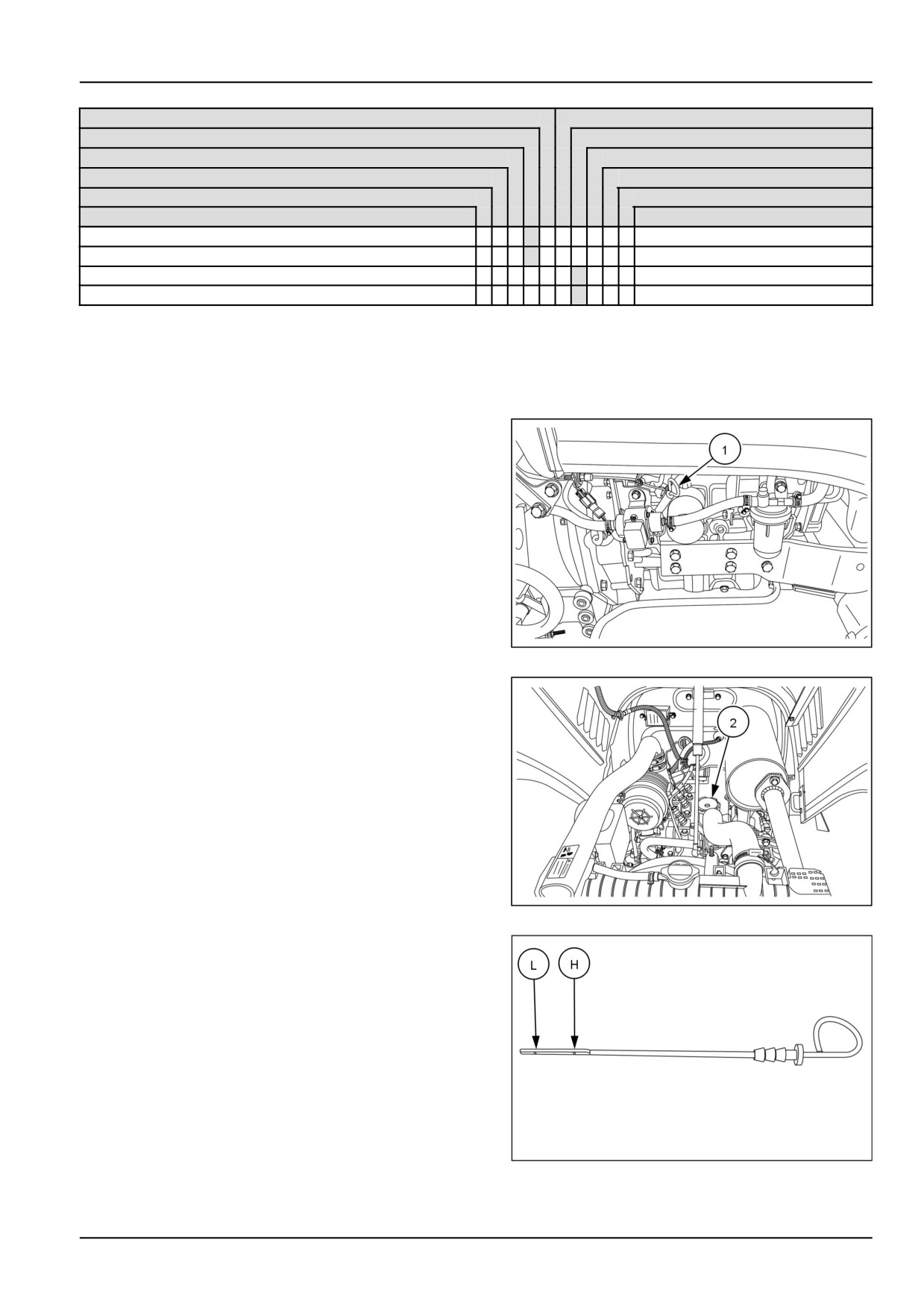
Tail light and brake light bulb - Replace
x
7-50
Turn signal and hazard bulb - Replace
x
7-51
Front wheels toe-in - Check
x
7-53
Belt - Adjust
x
7-54
Every 8 hours or daily
Engine lubrication system - Check
1. Before starting the tractor check the oil level using the
dipstick (1).
NOTE: The dipstick is only accurate if the tractor is not
running and sitting on a level surface.
2. Remove the dipstick from the engine.
3. Wipe the dipstick with a lint-free cloth.
4. Insert the dipstick in the engine.
5. Remove the dipstick and read the oil level
6. The oil level should be between the (L) and (H). See
figure 3
NHIL17CT01436AA
1
7. If the oil level is low, remove the filler cap (2) add oil
through the filler hole.
NHIL17CT01439AA
2
8. Add enough oil so that the level registers between the
two marks on the dipstick. Do not overfill.
93100903
3
7-9
7 - MAINTENANCE
Engine cooling system - Check
Cooling system
WARNING
Hot liquid under pressure!
Scalding can result from fast removal of the radiator cap. Check and service the engine cooling sys-
tem according to the maintenance instructions in this manual.
Failure to comply could result in death or serious injury.
W0163A
The tractor engine must operate at the correct temperature to obtain maximum efficiency and service life. This is
dependent on the cooling system.
Only check the cooling system when the engine is “OFF” and the cooling system is cool. Never add coolant to a
hot cooling system. Never remove the radiator cap when the cooling system is hot.
Always fill the system with a 50/50 solution of ethylene
glycol antifreeze and water.
Checking the coolant level
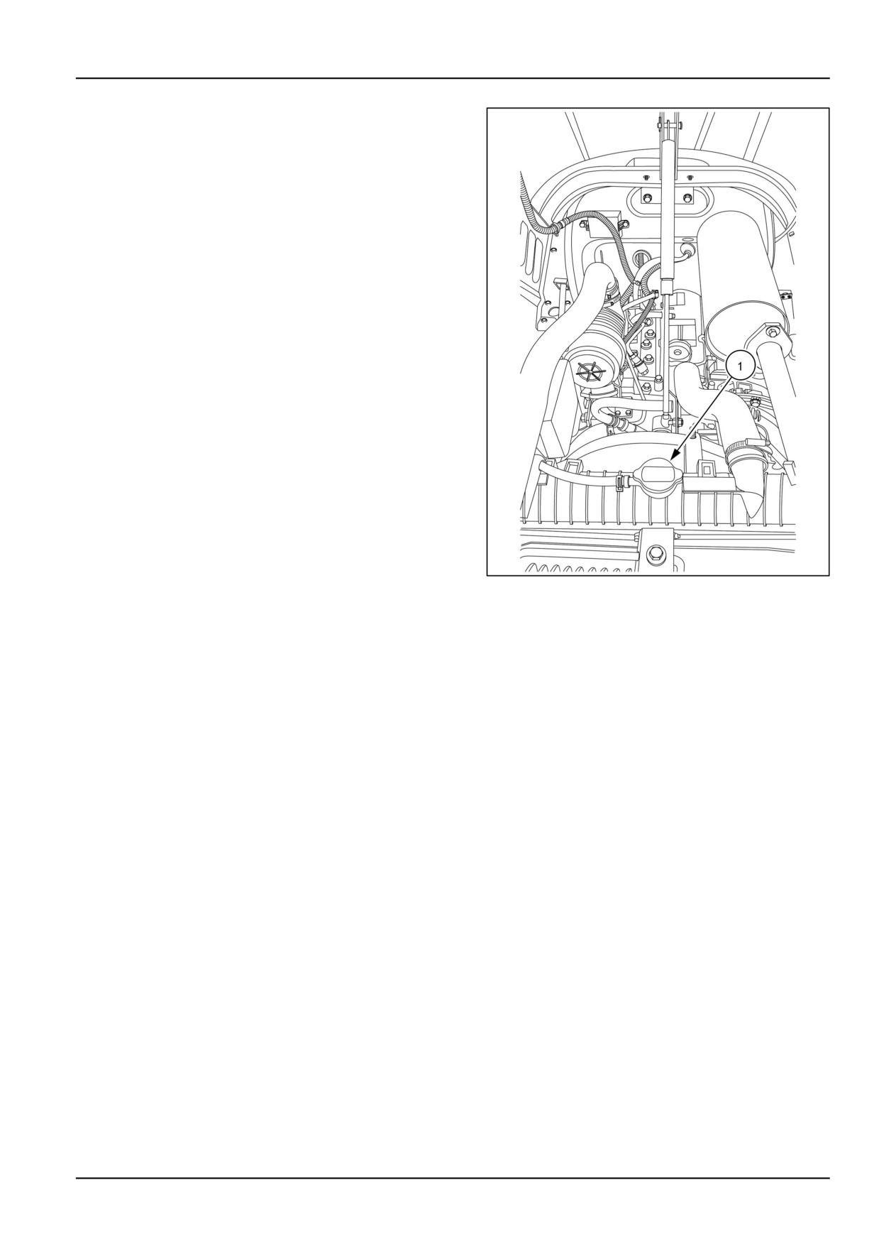
1. Visually inspect the coolant level in the coolant recov-
ery reservoir (1) the coolant level should be between
the "LOW" and "FULL" lines located on the side of the
reservoir.
2. If the coolant level is not between the "LOW" and
"FULL" lines, add coolant as necessary. The cooling
system already contains antifreeze, add only antifreeze
solution of the correct water/antifreeze mixture. Pure
water will dilute the solution and weaken its protection.
NHIL17CT01441AA
1
7-10
7 - MAINTENANCE
3. If there is not coolant in the coolant recovery reservoir
remove the cap (2) from the radiator.
NOTE: Only remove the radiator cap when the cooling sys-
tem is cool.
4. Add enough coolant to the radiator so the coolant level
is even with the bottom of the filler neck.
5. Install the radiator cap.
NHIL17CT01424BA
2
7-11
7 - MAINTENANCE
Transmission - Check
NOTE: The transmission, rear axle and hydraulic system
share a common sump..
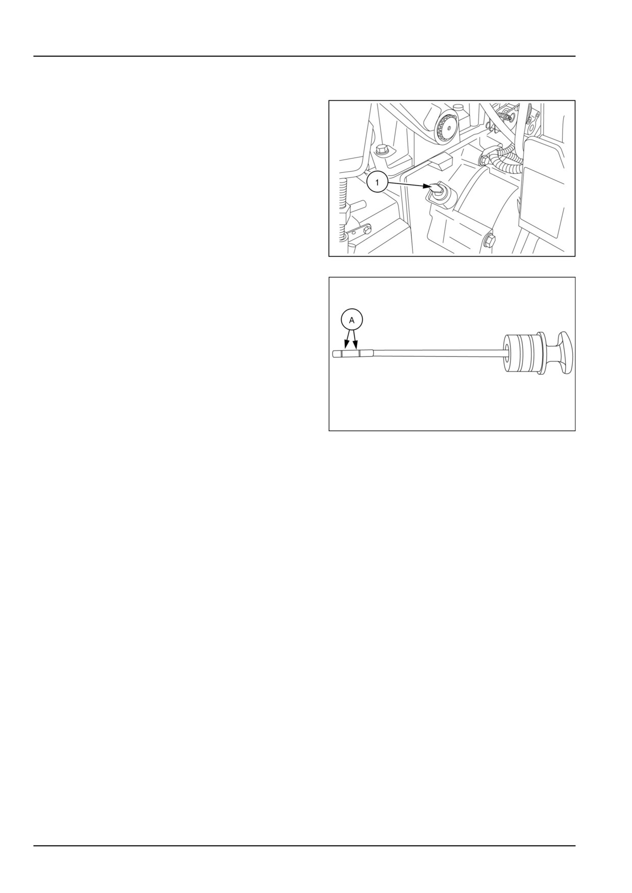
1. With the engine off and the tractor standing level, check
the oil level using the dipstick (1).
NHIL12CT00684AA
1
2. The oil is at the correct level when it reads between the
two marks (A) on the dipstick. If the level is low, add
HYDRAULIC TRANSMISSION OIL - PREMIUM hydraulic oil
through the dipstick hole. Do not fill above the dipstick
full mark.
3. Reinstall the dipstick.
93100904
2
7-12
7 - MAINTENANCE
Radiator screen cleaning
WARNING
Avoid injury!
Shut off the engine, remove the key, and make sure all machine motion stops before you service the
machine.
Failure to comply could result in death or serious injury.
W1128B
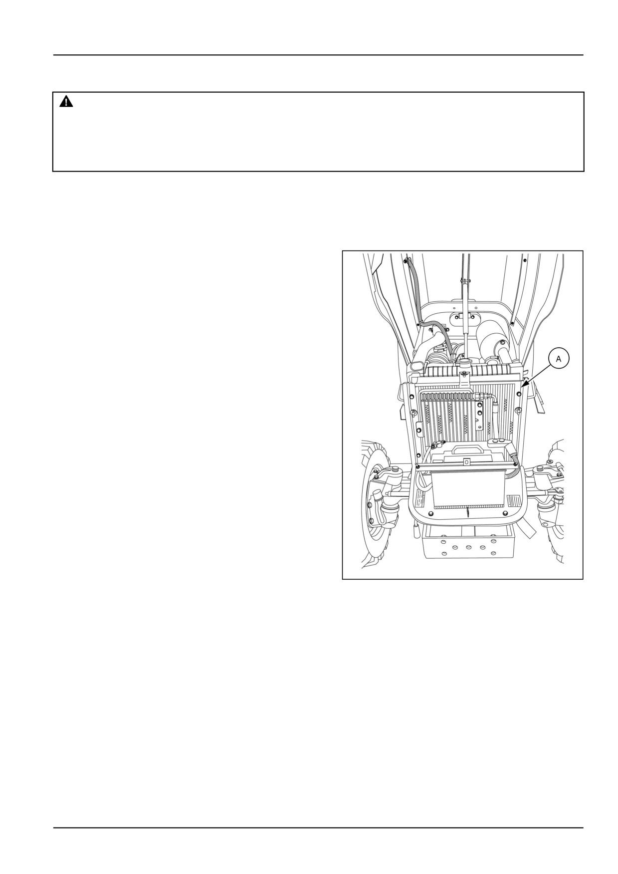
Clean the radiator screen daily before starting work. If you observe the engine coolant temperature gauge
approaching the red or “H” range while operating the tractor inspect the condition of the radiator screen. Shut
off the engine before servicing the radiator screen.
To clean the radiator screen perform the following.
1. Shut off the engine.
2. Remove the key.
3. Apply the park brake.
4. Open the hood.
5. Remove the radiator screen (A).
6. Remove the debris from the radiator screen.
7. Install the radiator screen.
8. Close the hood.
NHIL17CT01425BA
1
7-13
7 - MAINTENANCE
After first 50 hours
Engine lubrication system - Change fluid
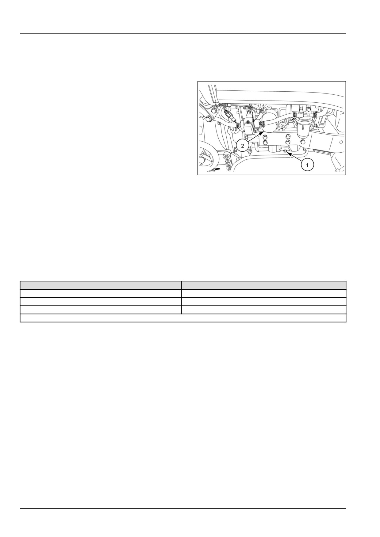
1. Place a suitable container beneath the drain opening
to catch the used oil..
2. With the tractor engine off but at normal operating tem-
perature, remove the drain plug (1)
3. Install the drain plug once the oil has drained from the
engine.
4. Place a container below the oil filter, (2) to catch the
used oil and unscrew the oil filter.
5. Discard the used oil and oil filter.
6. Coat the gasket on the new oil filter with a film of clean
oil.
NHIL17CT01436AA
1
7. Screw the filter in place until the gasket contacts its
mating surface, then turn the filter approximately three-
quarters of a turn by hand. Do not overtighten
8. Add the proper type and level of new oil, then start the
engine and check the filter for leaks.
NOTE: Oil Capacity, with filter 4.2 L (4.4 US qt)
Recommended Oils
Ambient Temp (°F)
Recommended Oil
-12 - 49 °C (10 - 120 °F)
SAE 15W-40 CI-4/CH-4 ENGINE OIL
-23.3 - 49 °C (-10 - 120 °F)
SAE 10W-30 CI-4 ENGINE OIL
-29 - 16 °C (-20 - 60 °F)
ENGINE OIL SAE 5W-30
Oil Specification API CF-4 or CH-4
NOTE: Tractors are originally shipped with (15W40) oil.
7-14
7 - MAINTENANCE
Fuel filters - Replace
NOTE: There is not a fuel shutoff valve on the fuel tank. To stop the fuel flow from the fuel tank, remove the fuel inlet
hose at the fuel filter base and plug it, or clamp the fuel hose to stop the fuel flow.
1. Close off the fuel inlet hose to the fuel filter.
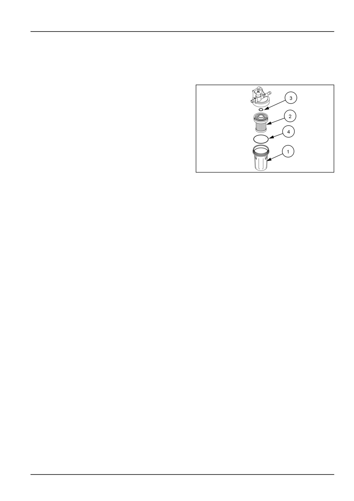
2. Remove the sediment bowl (1) by rotating the bowl from
the base.
3. Open fuel inlet hose, to drain any remaining water from
the tank.
4. Pull element with plastic base from fuel filter housing
(2) and install a new element.
5. Inspect the O-rings (3) and (4) and replace if necessary.
6. Install and securely tighten the sediment bowl.
7. Open the fuel inlet hose, so fuel will flow to the filter.
20100919A
1
8. Bleed the fuel system. See page 7-44.
7-15
7 - MAINTENANCE
Hydraulic oil suction filter - Replace
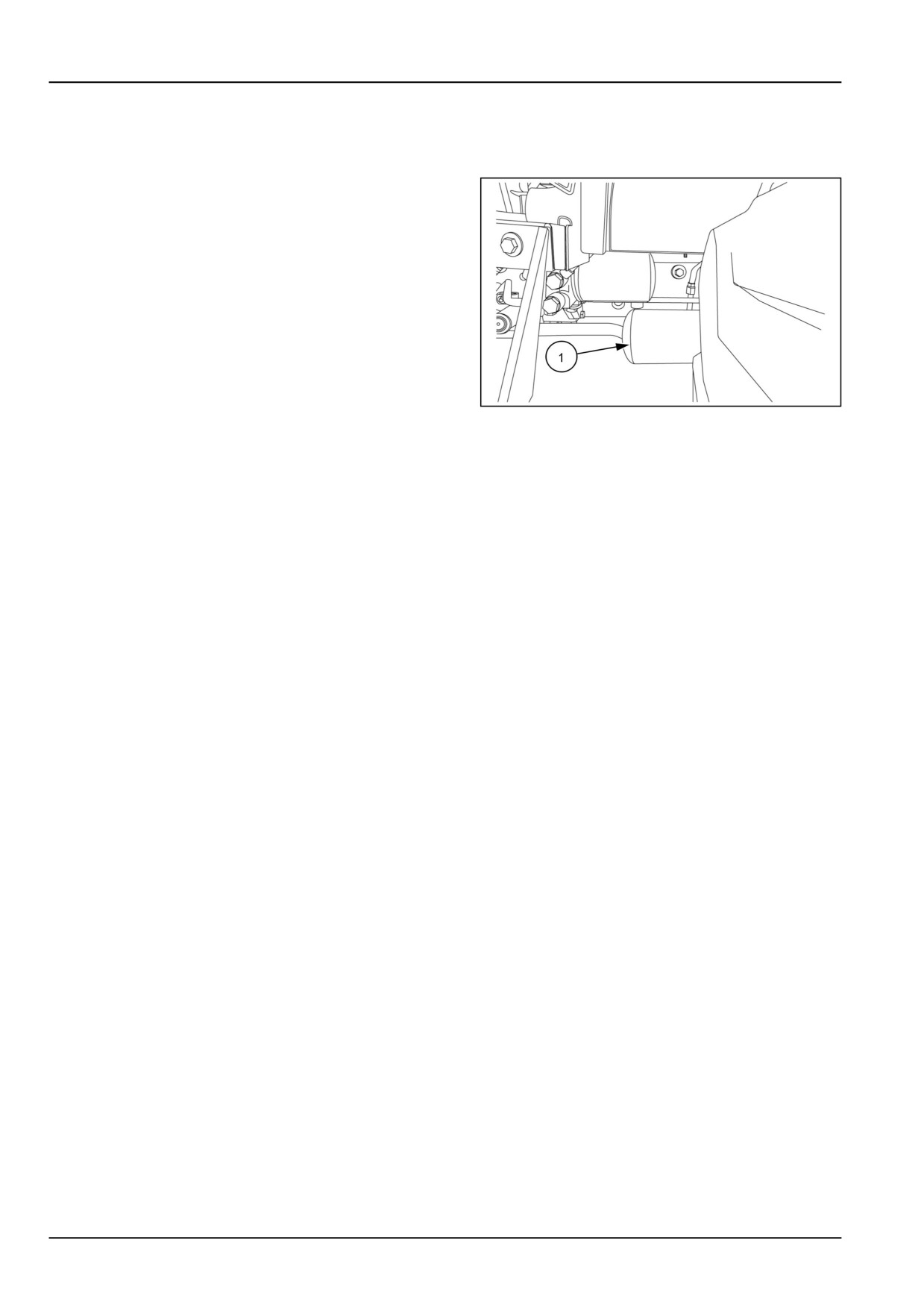
The hydraulic system uses a spin-on type oil filter, lo-
cated on the left side of the tractor underneath the op-
erator's platform. To replace the filter (1):
1. Unscrew the used oil filter and discard.
2. Coat the gasket on the new filter with a film of clean oil.
Screw the filter into place until the gasket contacts the
sealing surface, then tighten the filter by hand approxi-
mately three-quarters of a turn. Do not overtighten.
3. Start the engine and check the filter for leaks.
4. Stop the engine and check the hydraulic system oil
level. Add oil if necessary.
NHIL12CT00686AA
1
7-16

7 - MAINTENANCE
Hydrostatic Transmission (HST) oil filter - Replace
The hydrostatic system uses a spin-on type oil filter,
located on the left side of the tractor underneath the
operator's platform. To replace the filter (1):
1. Unscrew the used oil filter and discard.
2. Coat the gasket on the new filter with a film of clean oil.
Screw the filter into place until the gasket contacts the
sealing surface, then tighten the filter by hand approxi-
mately three-quarters of a turn. Do not overtighten.
3. Start the engine and check the filter for leaks.
4. Stop the engine and check the hydraulic system oil
level. Add oil if necessary.
NHIL12CT00686AA
1
7-17
7 - MAINTENANCE
Roll Over Protective Structure (ROPS) frame - Check
Maintenance and inspection
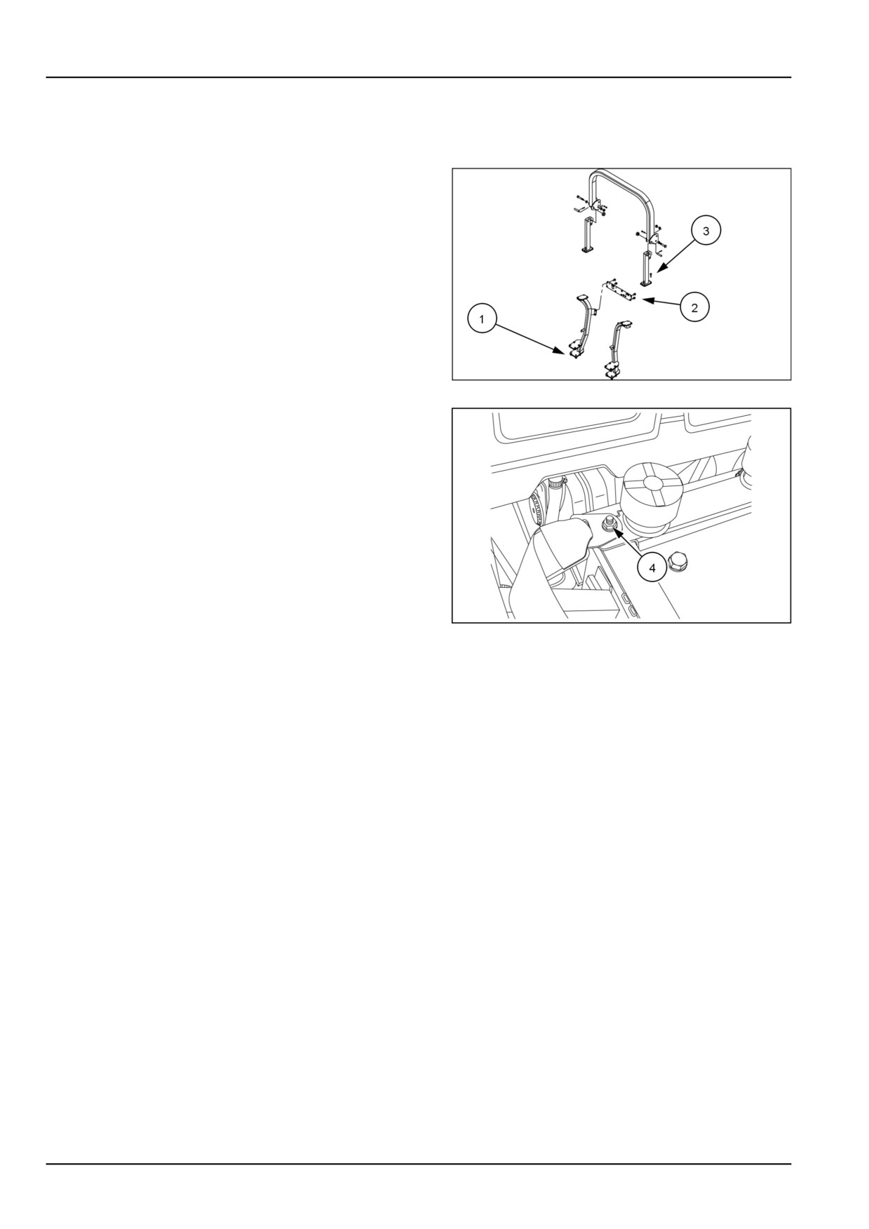
1. Check the torque of the ROPS bottom portion mounting
bolts, (1). Tighten the M14, bolts to the correct torque
of 147 N·m (108 lb ft) if necessary.
2. Check the torque of the Roll Over Protective Structure
(ROPS) cross brace mounting bolts (2). Tighten the
M10 bolts to the correct torque of 60 N·m (41 lb ft) if
necessary.
3. Check the torque of the ROPS top portion mounting
bolts (3). Tighten the M12, bolts to the correct torque
of 83 N·m (61 lb ft) if necessary.
230100876
1
4. Inspect the operator's seat and the mounting parts for
the seat belt. Tighten the bolts (4) to the correct torque
of 28 N·m (21 lb ft) if necessary and replace any parts
that show wear or damage.
NHIL12CT00838AA
2
7-18
7 - MAINTENANCE
Wheel hardware - Check
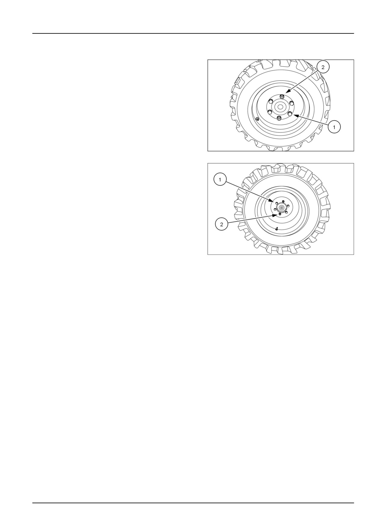
Tighten the wheel bolts (1) and nuts (2) to the specified
torque any time the wheel assembly is removed from
the tractor or the wheel bolts are loosened.
Front Wheel Torque
•
176 - 196 N·m (130 - 145 lb ft)
93100874
1
Rear Wheel Torque
•
176 - 196 N·m (130 - 145 lb ft)
NOTICE: Check and tighten wheel bolts (1) and nuts (2)
to proper torque specifications after the following hours of
use:
• First 5 hours
• First 50 hours
• Every 250 hours
93100875A
2
7-19
7 - MAINTENANCE
Every 50 hours
Machine fittings - Grease
1. To lubricate these points:
1. Wipe away all old grease and dirt from the lubrica-
tion fittings to prevent dirt or foreign material from
entering as new grease is applied.
2. Use a grease gun to pump in the new grease. Ap-
ply pressure until clean grease oozes from each
lubrication point.
3. Wipe away any excess grease.
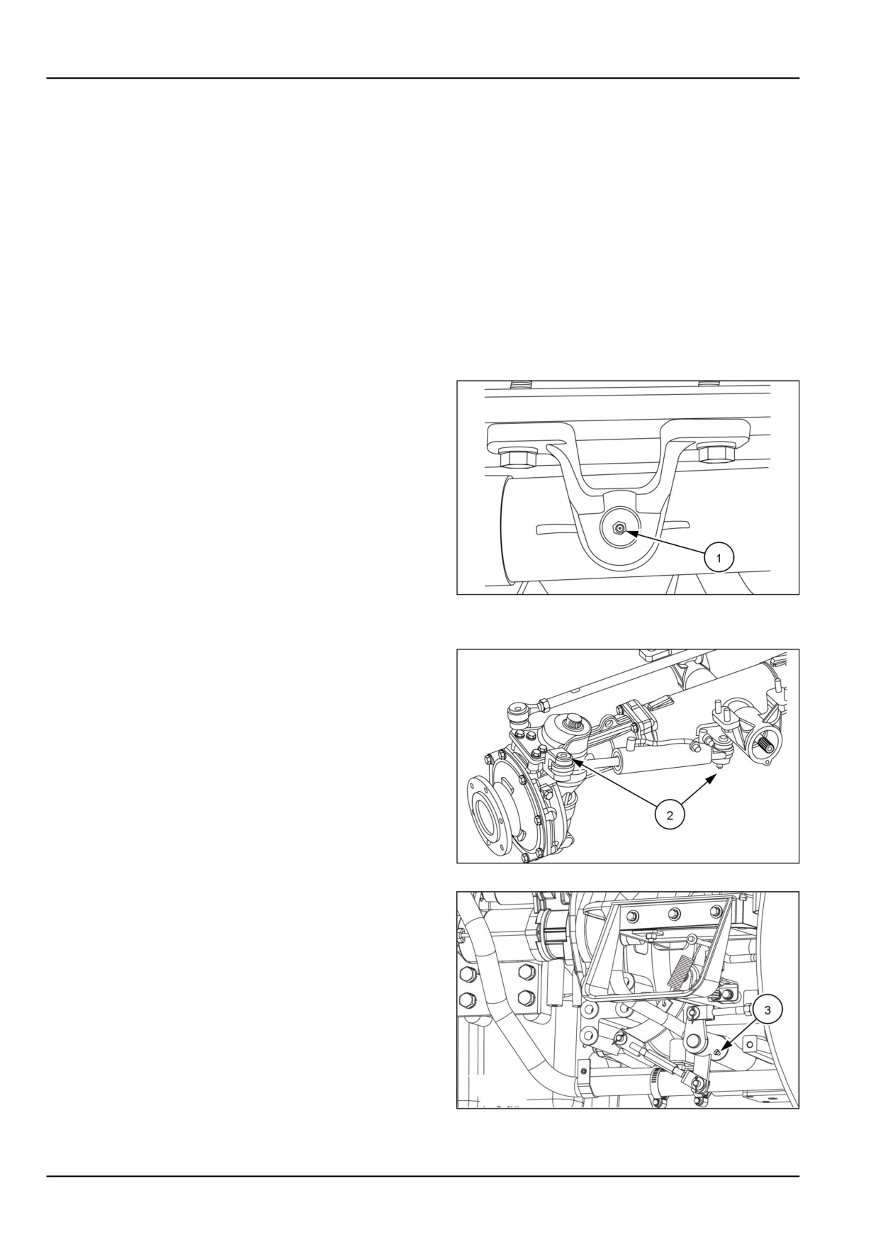
2. Front Axle Pivot (1)
93100890
1
3. Power Steering Cylinder (2)
93100864
2
4. Clutch Pedal Shaft (3) (Mechanical transmission)
NHIL13CT00158AA
3
7-20
7 - MAINTENANCE
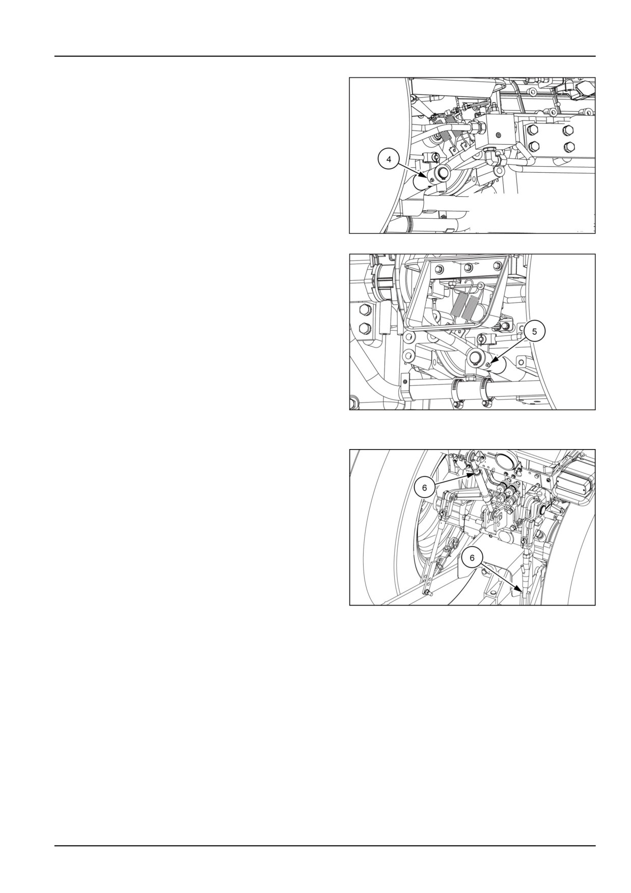
5. Brake pedals shaft (4) (Mechanical transmission)
NHIL13CT00157AA
4
6. Brake pedals shaft (5) (Hydrostatic transmission)
NHIL13CT00159AA
5
7.
3-Point Linkage (6) oil threads
NHIL12CT00821AA
6
7-21
7 - MAINTENANCE
Transmission - Check
NOTE: The transmission, rear axle and hydraulic system
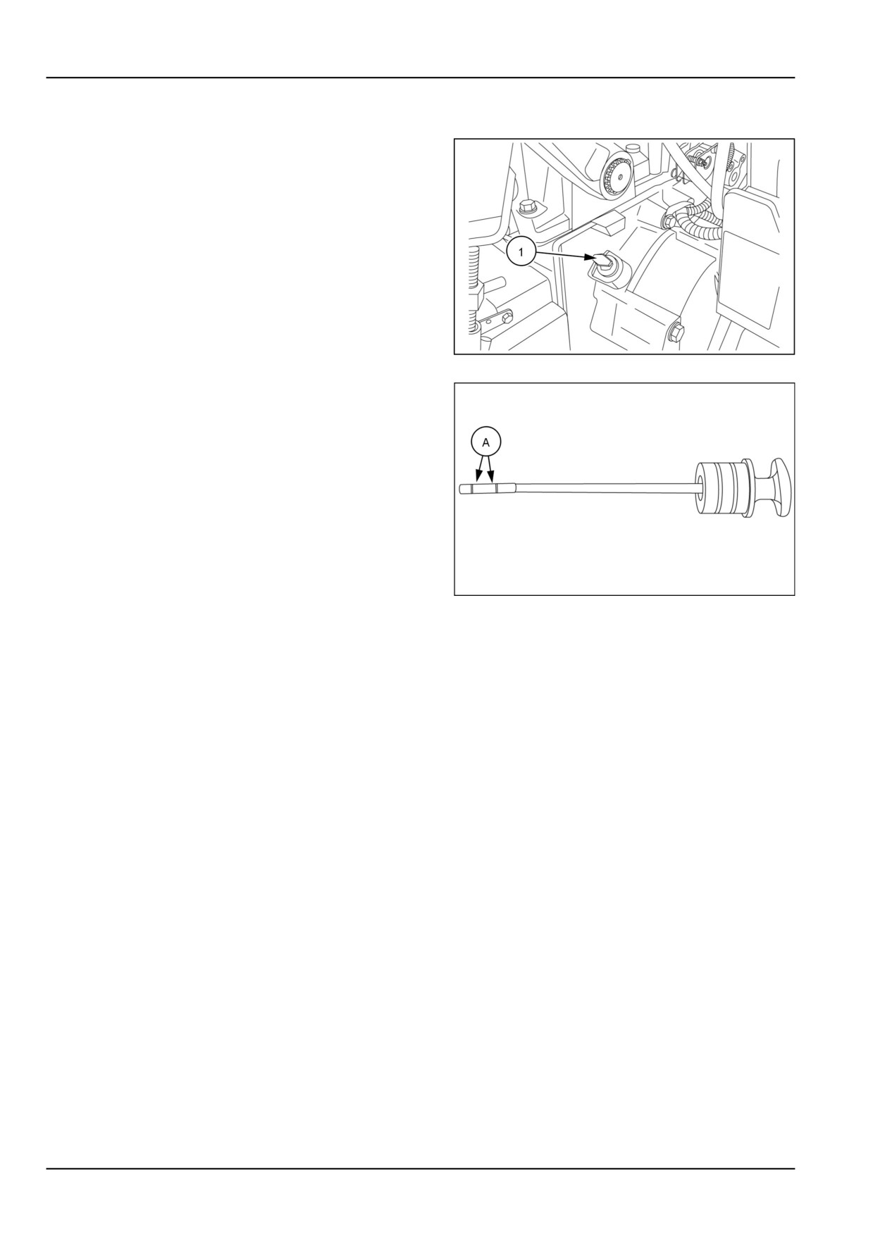
share a common sump..
1. With the engine off and the tractor standing level, check
the oil level using the dipstick (1).
NHIL12CT00684AA
1
2. The oil is at the correct level when it reads between the
two marks (A) on the dipstick. If the level is low, add
HYDRAULIC TRANSMISSION OIL - PREMIUM hydraulic oil
through the dipstick hole. Do not fill above the dipstick
full mark.
3. Reinstall the dipstick.
93100904
2
7-22
7 - MAINTENANCE
Tire pressure - Check
WARNING
Explosion hazard!
Always maintain correct tire pressure as indicated in this manual. DO NOT inflate tires above the
recommended pressure. Excessive pressure could result in tire failure.
Failure to comply could result in death or serious injury.
W0109A
Tire inflation pressure affects the amount of weight a tire can carry. Check the air pressure in your tractor tires and
adjust the tire pressure, being careful not to overinflate or under inflate. Observe the following guidelines:
•
Do not inflate a tire above the maximum pressure shown on the tire. If the tire is not marked, do not exceed the
maximum pressure shown in the Tire Inflation chart found in this manual.
•
Do not reinflate a tire that has been run flat or seriously under inflated until the tire has been inspected for
damage by a qualified person.
•
When checking tire pressure, inspect the tire for damaged sidewalls and tread cuts. Neglected damage leads to
early tire failure.
If
you must inflate or service tires, follow these safety precautions to avoid injury or fatality:
•
Make sure the rim is clean and free of rust.
•
Lubricate both tire beads and rim flanges with soap solution. Do not use oil or grease.
•
Use a clip-on tire chuck with a remote hose and gauge. This allows the operator to stand clear of the tire
while inflating.
•
NEVER INFLATE TO OVER 241 kPa (35 psi) TO SEAT BEADS. If beads have not been seated by the time
pressure reaches 241 kPa (35 psi), deflate the assembly, reposition the tire on the rim, relubricate both tire bead
and rim flanges, and reinflate. Inflation beyond 241 kPa (35 psi) with unseated beads may break the bead or rim
with explosive force sufficient enough to cause serious injury.
•
After seating the beads, adjust inflation pressure to recommended operating pressure.
•
Do not inflate a tire unless the rim is mounted on the tractor or is secured so that it will not move if the tire or
rim should suddenly fail.
•
Do not weld, braze, otherwise repair, or use a damaged rim.
•
Never attempt tire repairs on a public road or highway.
•
Use jack stands or other suitable blocking to support the tractor while repairing tires.
•
Ensure jack has adequate capacity to lift your tractor.
•
Place jack on a firm, level surface.
•
Do not place any part of your body beneath the tractor or start the engine while the tractor is on the jack.
•
Before adding ballast to the tires, refer to page 6-1 for tire and tractor ballasting information.
7-23
7 - MAINTENANCE
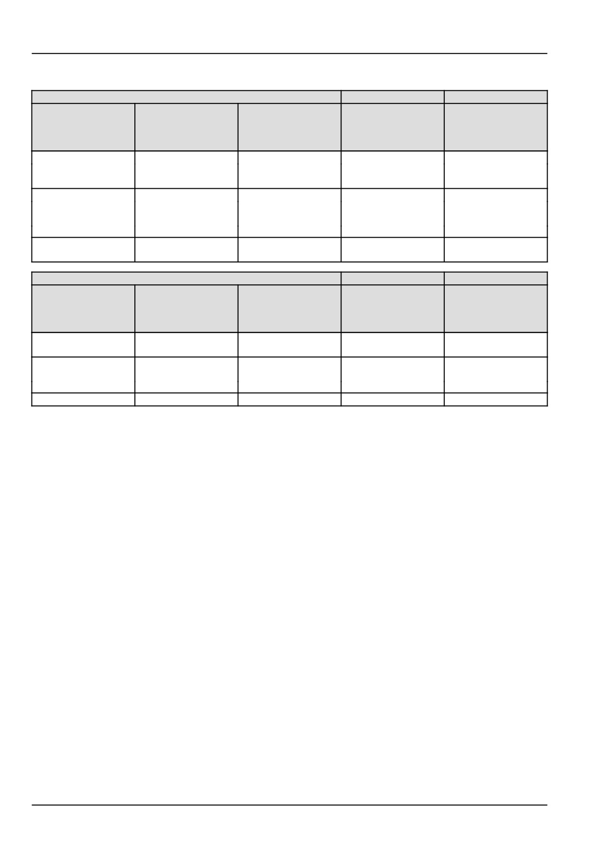
Tire inflation pressures
Front tire inflation pressures
Tire Type
Maximum load
Maximum load
Recommended air
capacity at
capacity at
Tire Size
pressure
Minimum inflation
maximum inflation
pressure
pressure
Agricultural (R1)
41 - 248 kPa (6 -
7-14, 4PR, R1
160 kg (353 lb)
449 kg (990 lb)
36 psi)
Turf (R3)
34 - 152 kPa (5 -
25 x 8.50-14, 4PR, R3
251 kg (553 lb)
599 kg (1321 lb)
22 psi)
Industrial (R4)
207 - 345 kPa (30 -
25 x 8.50-14, 6PR, R4
716 kg (1579 lb)
966 kg (2130 lb)
50 psi)
Rear tire inflation pressures
Tire Type
Maximum load
Maximum load
Recommended air
capacity at
capacity at
Tire Size
pressure
minimum inflation
maximum inflation
pressure
pressure
Agricultural (R1)
83 - 124 kPa (12 -
11.2-24, 4PR, R1
454 kg (1001 lb)
1152 kg (2540 lb)
18 psi)
Turf (R3)
41 x 14.00-20, 4PR,
69 - 172 kPa (10 -
825 kg (1819 lb)
1397 kg (3080 lb)
R3
25 psi)
Industrial (R4)
43 x16-20, 4PR, R4
138 kPa (20 psi)
2059.0 kg (4539.3 lb)
2059.0 kg (4539.3 lb)
NOTE: Do not under inflate or overinflate tires. Do not exceed maximum inflation pressure listed.
7-24
7 - MAINTENANCE
Clutch Pedal Free Play - Check
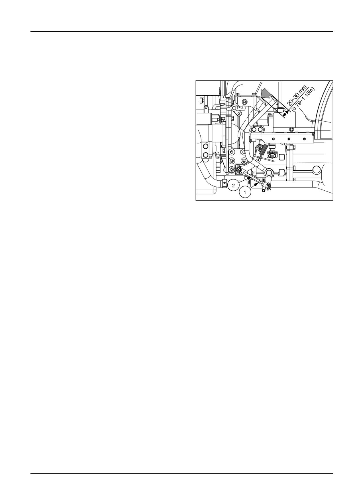
Clutch pedal free travel should be maintained at A = 20
- 30 mm (0.79 - 1.18 in).
To adjust the clutch pedal:
1. Loosen lock nut (1) and rotate adjuster (2)
2. Tightening the adjuster will decrease the free play travel
and loosening the adjuster will increase the free play
travel.
3. Tighten the lock nut when the correct free play travel is
obtained
4. Check clutch for disengagement when clutch pedal is
fully depressed.
NOTE: Contact your NEW HOLLAND dealer with any
questions you have concerning this procedure.
NHIL12CT00783AA
1
7-25
7 - MAINTENANCE
Hydrostatic transmission (HST) neutral adjustment - Check
1. Start the tractor on a smooth level surface.
2. Release the park brake.
3. Set the engine speed to 2500 RPM.
4. Select “L” transmission range.
5. Completely depress the forward travel pedal.
6. Release the forward travel pedal.
7. The tractor should slow down and come to a complete
stop. If it does not stop make note of that condition.
8. Perform the same operation for reverse.
9. The tractor should slow down and come to a complete
stop once the forward and reverse pedals are released.
Contact your NEW HOLLAND dealer for neutral adjust-
ment if your tractor does not come to a complete stop.
7-26

7 - MAINTENANCE
Belt - Check
1. A belt-driven fan located at the front of the engine draws
air through the fins of the radiator to lower the temper-
ature of the radiator coolant.
2. When 10 kg (22 lb) of pressure is applied midway (A)
between the belt pulleys, a correctly tightened belt will
deflect 10 - 12 mm (0.4 - 0.5 in).
3. If the fan belt is slipping, fan efficiency is lowered, re-
sulting in the engine running too hot. If the belt is too
tight, the life of the alternator bearing will be shortened.
If the fan belt shows signs of cracking or fraying, install
a new one.
4. If the belt requires adjustment see page 7-54 for this
procedure.
93100870
1
7-27
7 - MAINTENANCE
Mechanical service brakes - Check
Whenever brake pedal travel becomes excessive, or if
the travel of one pedal is unequal to that of the other,
each pedal should be adjusted.
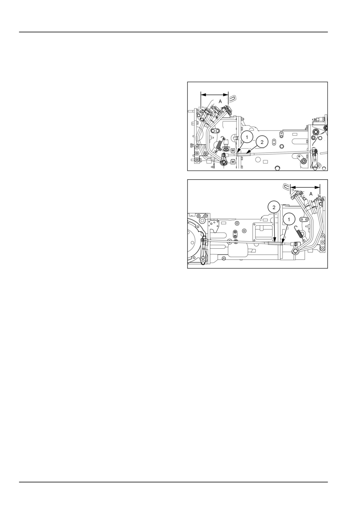
1. Loosen the locknut (1) and rotate the brake rod (2) until
there is (A) = 50 - 60 mm (1.97 - 2.36 in) of pedal free
play. Lengthening the rod increases free play. Short-
ening the rod decreases free play.
2. Test drive the tractor to make sure the braking action of
both rear wheels is equal. Readjust as necessary.
NOTE: Note Hydrostatic transmission tractors are shown
in figure 1 and mechanical transmission tractors are shown
in figure 2.
NOTE: Contact your NEW HOLLAND dealer with any
questions you have concerning this procedure.
NHAC13CT00055AA
1
NHAC13CT00139AA
2
7-28
7 - MAINTENANCE
Front axle differential fluid level - Check
1. With the tractor standing level and the engine off, check
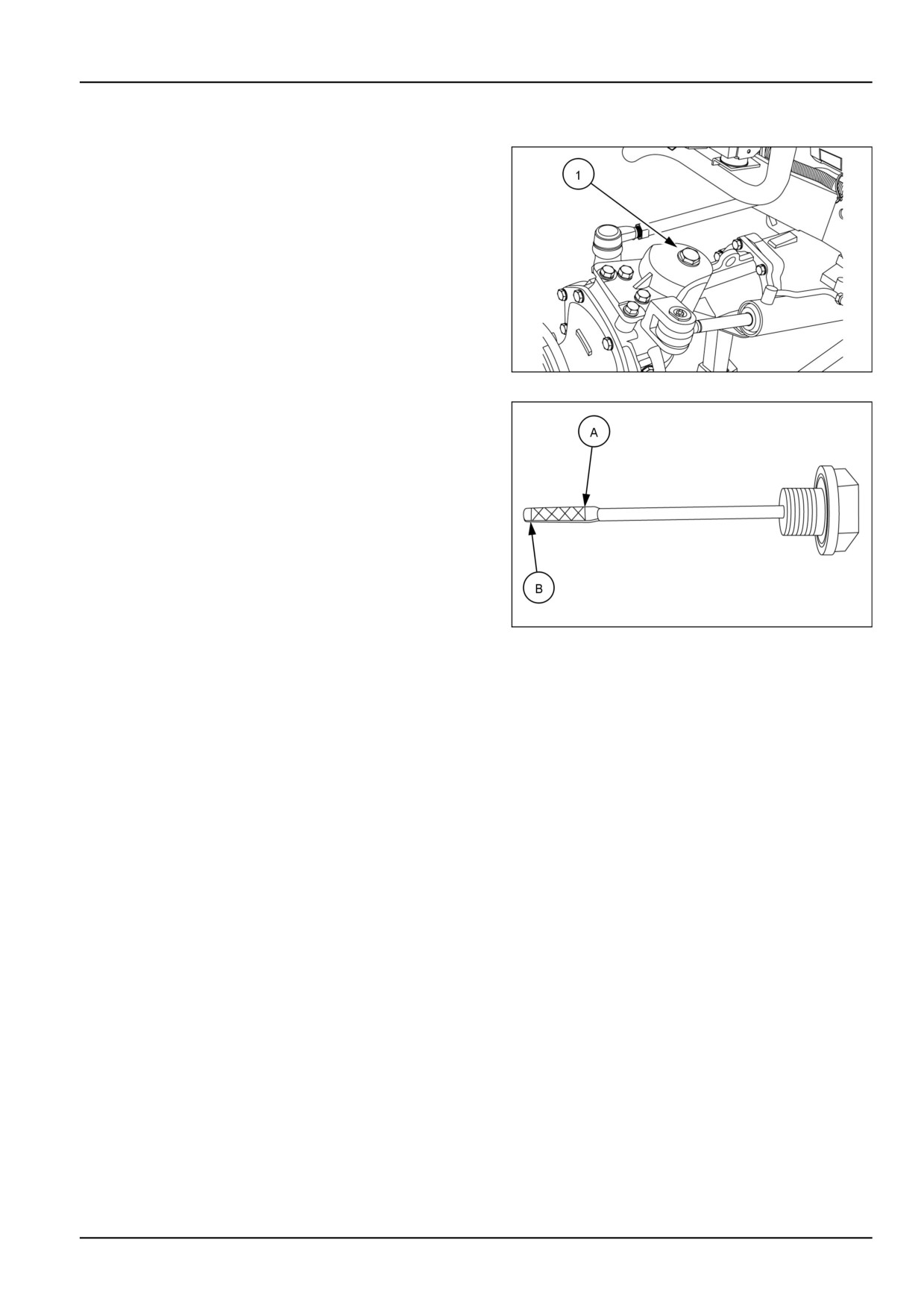
the front axle oil level using the dipstick (1). located on
the left side of axle.
93100889
1
2. The oil is at the correct level when it reads between the
upper (A) and the lower (B) marks of the dipstick.
3. If capacity is low, add HYPOID GEAR OIL EXTREME
PRESSURE 80W-90 oil through the combined dip-
stick/filler plug. Do not fill beyond the dipstick full
mark, or the front axle and differential housing will be
overfilled.
4. Install the dipstick/filler plug.
93100902
2
7-29
7 - MAINTENANCE
Air cleaner - Outer element - Cleaning
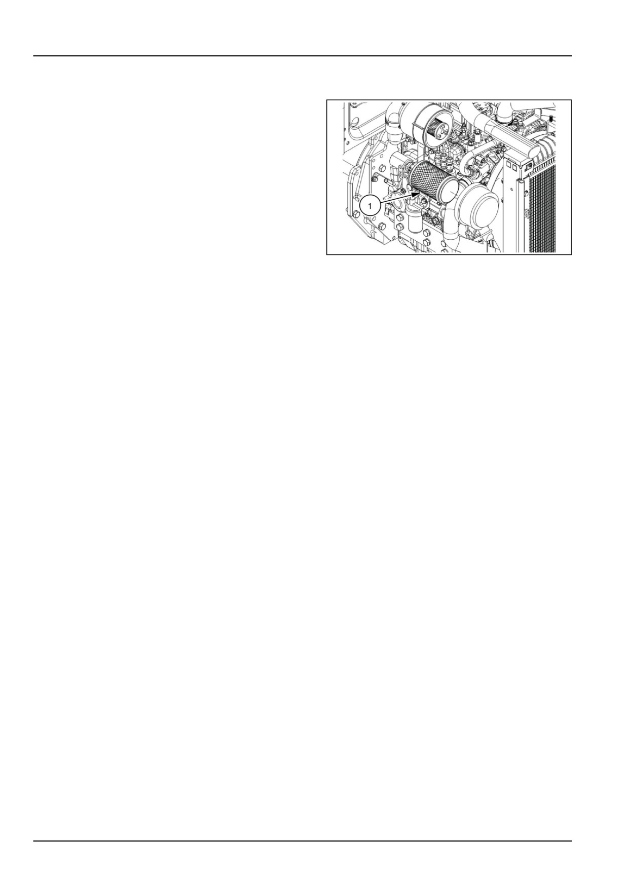
1. Pull the outer element (1) from the canister. Clean any
loose dirt from the canister and inspect the end of the
canister for dirt which may prevent the new element
from sealing properly.
2. Clean the outer element using low air pressure ( 2 Kg/
cm² (30 psi) or less). Blow dust from the inside to
the outside of the element (opposite to normal air flow
through element).
NOTICE: Be careful not to rupture the filter element. Main-
tain a safe distance between the air nozzle and the filter
element when directing air up and down the clean air side
of the element pleats.
NHIL17CT01804FA
1
3. After cleaning the element, check the inner diameter
seals for damage. If damage is present, replace the
outer element.
4. Reinstall the outer element by inserting it into the can-
ister and pushing on the end of the element until it is
seated against the canister.
NOTE: Place a light inside the element to check for paper
leaks or for bonding of the paper to the end plate. If any
leaks are found, replace the element.
NOTE: If element is not inserted far enough into canister,
the end cap cannot be installed.
5. Place the end cap onto the canister body, push in on
end cap, and rotate clockwise. Make sure the end cap
is locked in place and not loose.
NOTICE: Never tap the element with hard objects or
against a hard surface. This may dent or break the ele-
ment end cap seals.
NOTICE: Failure to obtain a good seal between elements
and the canister may cause major engine damage.
7-30
7 - MAINTENANCE
Every 250 hours
Engine lubrication system - Change fluid
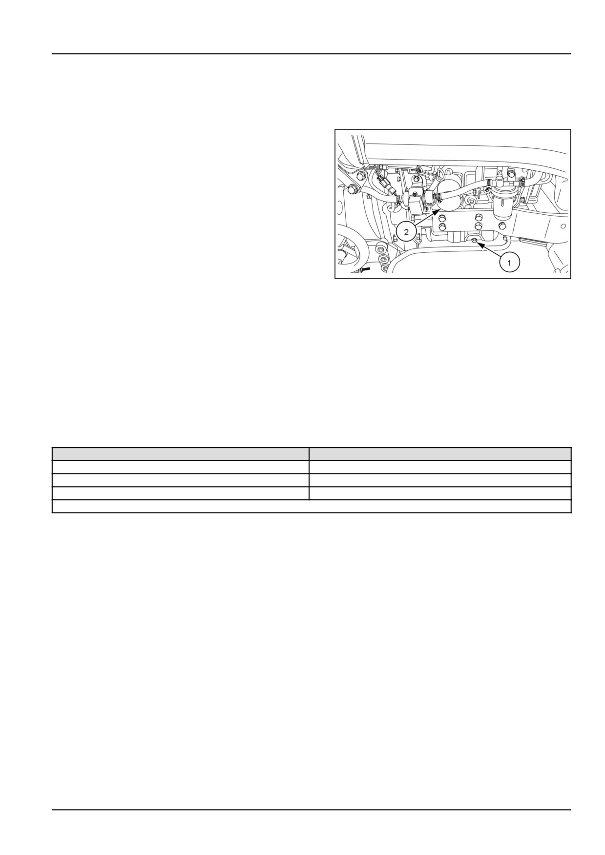
1. Place a suitable container beneath the drain opening
to catch the used oil..
2. With the tractor engine off but at normal operating tem-
perature, remove the drain plug (1)
3. Install the drain plug once the oil has drained from the
engine.
4. Place a container below the oil filter, (2) to catch the
used oil and unscrew the oil filter.
5. Discard the used oil and oil filter.
6. Coat the gasket on the new oil filter with a film of clean
oil.
NHIL17CT01436AA
1
7. Screw the filter in place until the gasket contacts its
mating surface, then turn the filter approximately three-
quarters of a turn by hand. Do not overtighten
8. Add the proper type and level of new oil, then start the
engine and check the filter for leaks.
NOTE: Oil Capacity, with filter 4.2 L (4.4 US qt)
Recommended Oils
Ambient Temp (°F)
Recommended Oil
-12 - 49 °C (10 - 120 °F)
SAE 15W-40 CI-4/CH-4 ENGINE OIL
-23.3 - 49 °C (-10 - 120 °F)
SAE 10W-30 CI-4 ENGINE OIL
-29 - 16 °C (-20 - 60 °F)
ENGINE OIL SAE 5W-30
Oil Specification API CF-4 or CH-4
NOTE: Tractors are originally shipped with (15W40) oil.
7-31
7 - MAINTENANCE
Fuel filters - Replace
NOTE: There is not a fuel shutoff valve on the fuel tank. To stop the fuel flow from the fuel tank, remove the fuel inlet
hose at the fuel filter base and plug it, or clamp the fuel hose to stop the fuel flow.
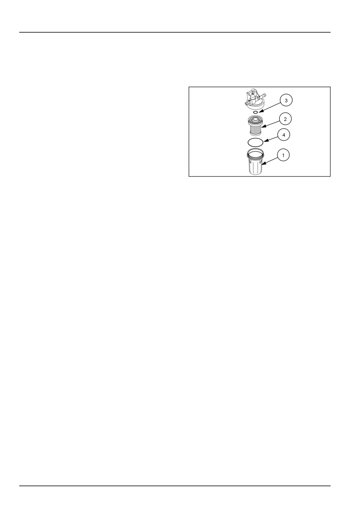
1. Close off the fuel inlet hose to the fuel filter.
2. Remove the sediment bowl (1) by rotating the bowl from
the base.
3. Open fuel inlet hose, to drain any remaining water from
the tank.
4. Pull element with plastic base from fuel filter housing
(2) and install a new element.
5. Inspect the O-rings (3) and (4) and replace if necessary.
6. Install and securely tighten the sediment bowl.
7. Open the fuel inlet hose, so fuel will flow to the filter.
20100919A
1
8. Bleed the fuel system. See page 7-44.
7-32
7 - MAINTENANCE
Oil filter - Replace
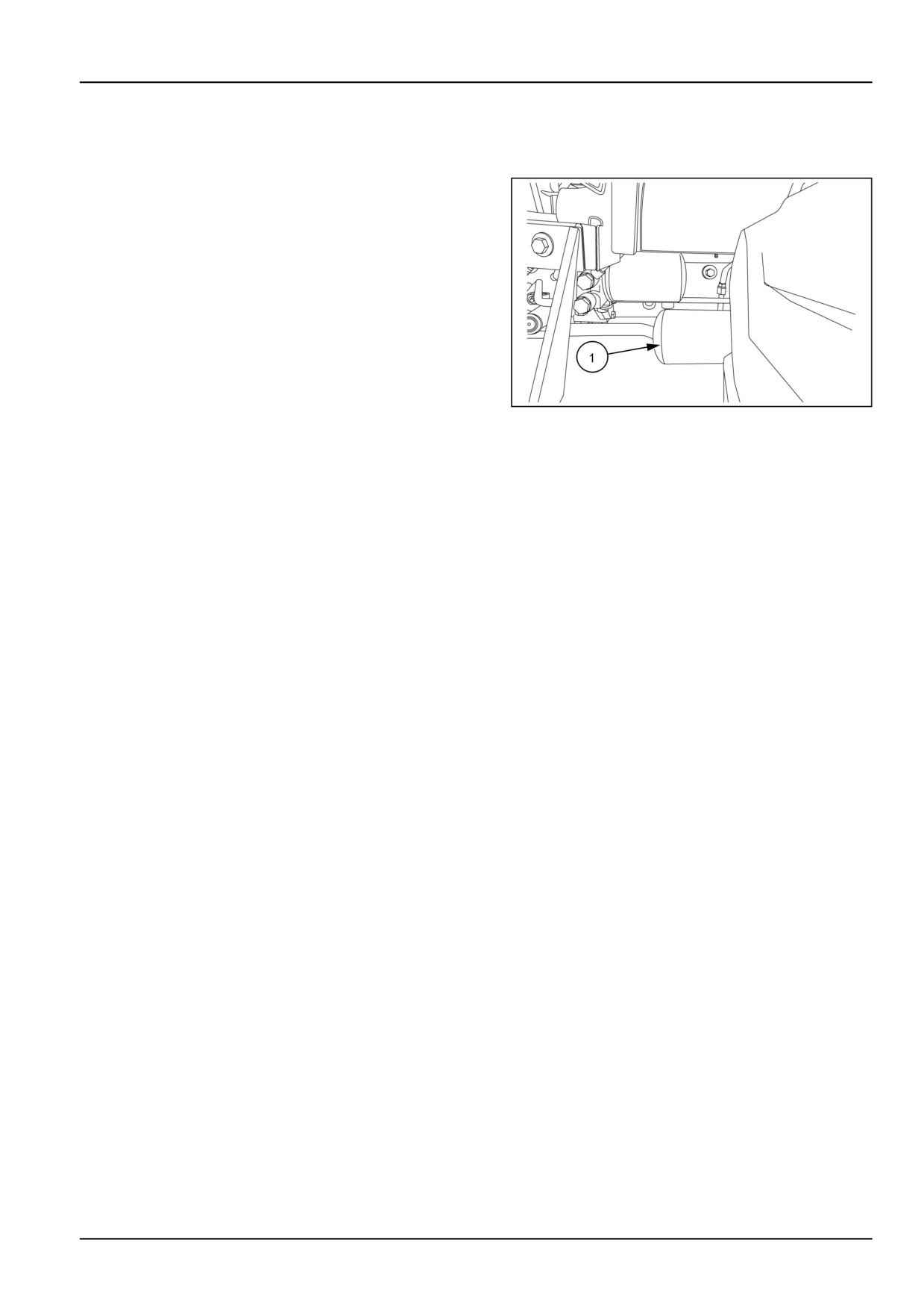
The hydraulic system uses a spin-on type oil filter, lo-
cated on the left side of the tractor underneath the op-
erator's platform. To replace the filter (1):
1. Unscrew the used oil filter and discard.
2. Coat the gasket on the new filter with a film of clean oil.
Screw the filter into place until the gasket contacts the
sealing surface, then tighten the filter by hand approxi-
mately three-quarters of a turn. Do not overtighten.
3. Start the engine and check the filter for leaks.
4. Stop the engine and check the hydraulic system oil
level. Add oil if necessary.
NHIL12CT00686AA
1
7-33
7 - MAINTENANCE
Oil filter - Replace
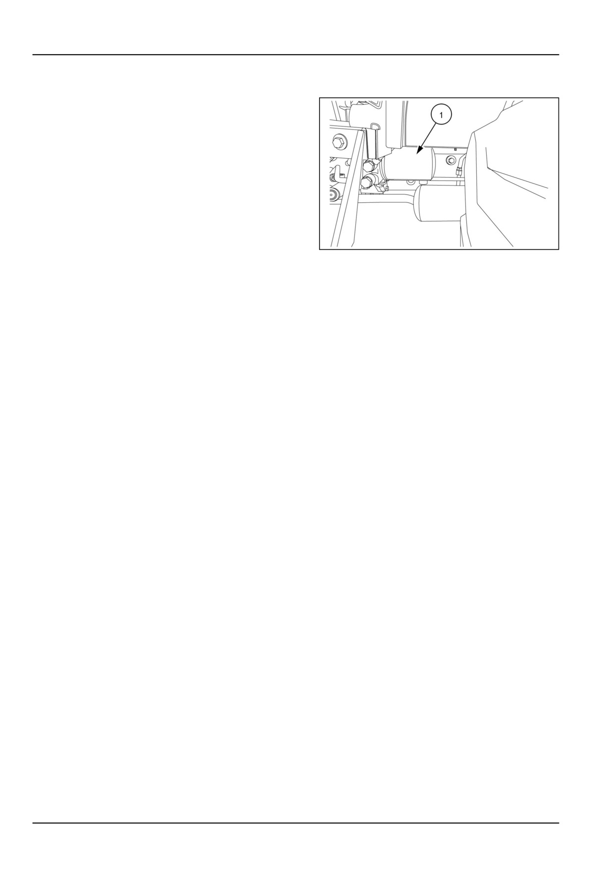
The hydrostatic system uses a spin-on type oil filter,
located on the left side of the tractor underneath the
operator's platform. To replace the filter (1):
1. Unscrew the used oil filter and discard.
2. Coat the gasket on the new filter with a film of clean oil.
Screw the filter into place until the gasket contacts the
sealing surface, then tighten the filter by hand approxi-
mately three-quarters of a turn. Do not overtighten.
3. Start the engine and check the filter for leaks.
4. Stop the engine and check the hydraulic system oil
level. Add oil if necessary.
NHIL12CT00686AA
1
7-34
7 - MAINTENANCE
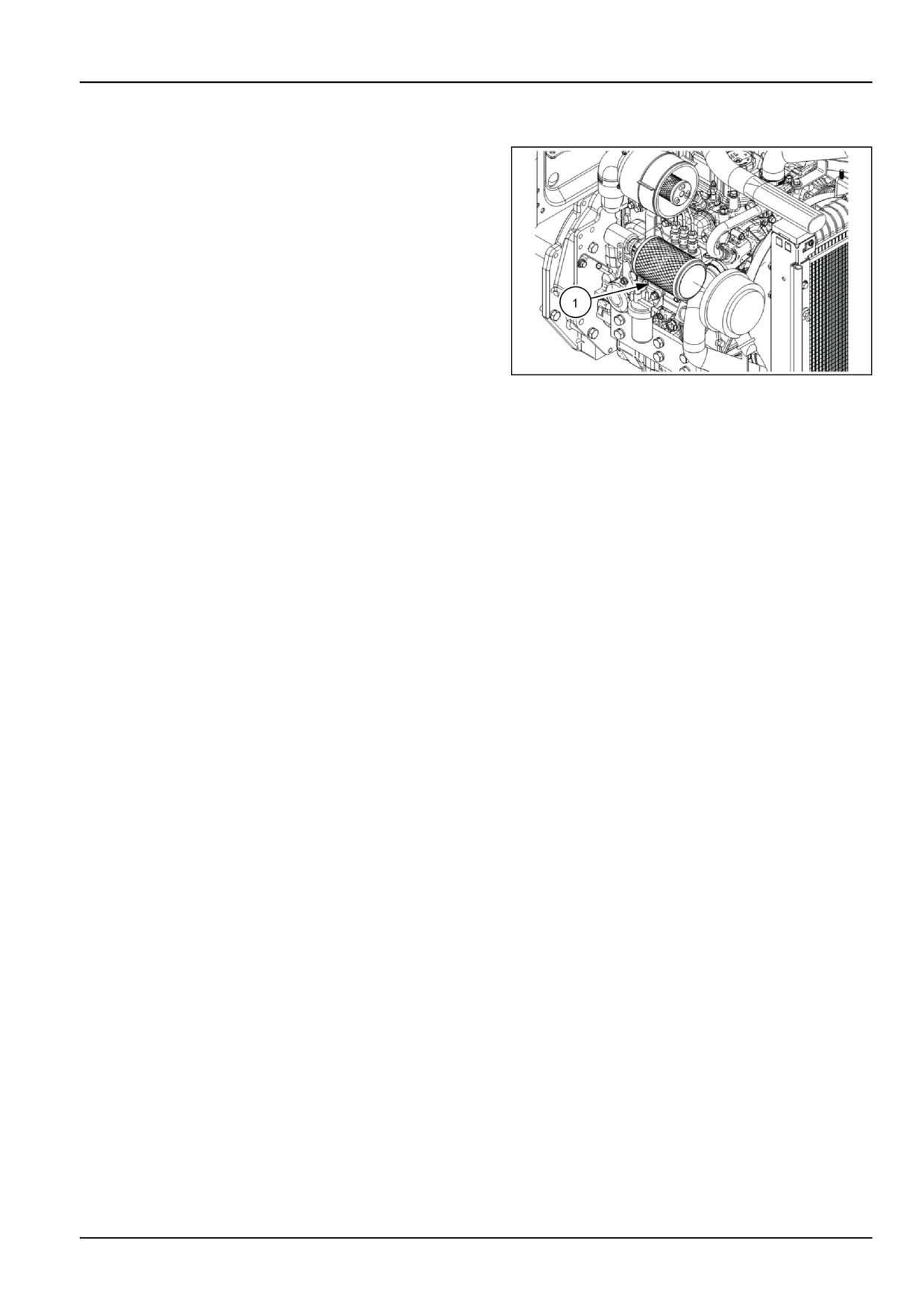
Air cleaner - Outer element - Replace
1. Pull the outer element (1) from the canister. Clean any
loose dirt from the canister and inspect the end of the
canister for dirt which may prevent the new element
from sealing properly.
2. Install the new outer element by inserting it into the
canister and pushing on the end of the element until
it is seated against the canister.
NOTE: If element is not inserted far enough into canister,
the end cap cannot be installed.
3. Place the end cap onto the canister body, push in on
end cap, and rotate clockwise. Make sure the end cap
is locked in place and not loose.
NHIL17CT01804FA
1
NOTICE: Failure to obtain a good seal between elements
and the canister may cause major engine damage.
7-35
7 - MAINTENANCE
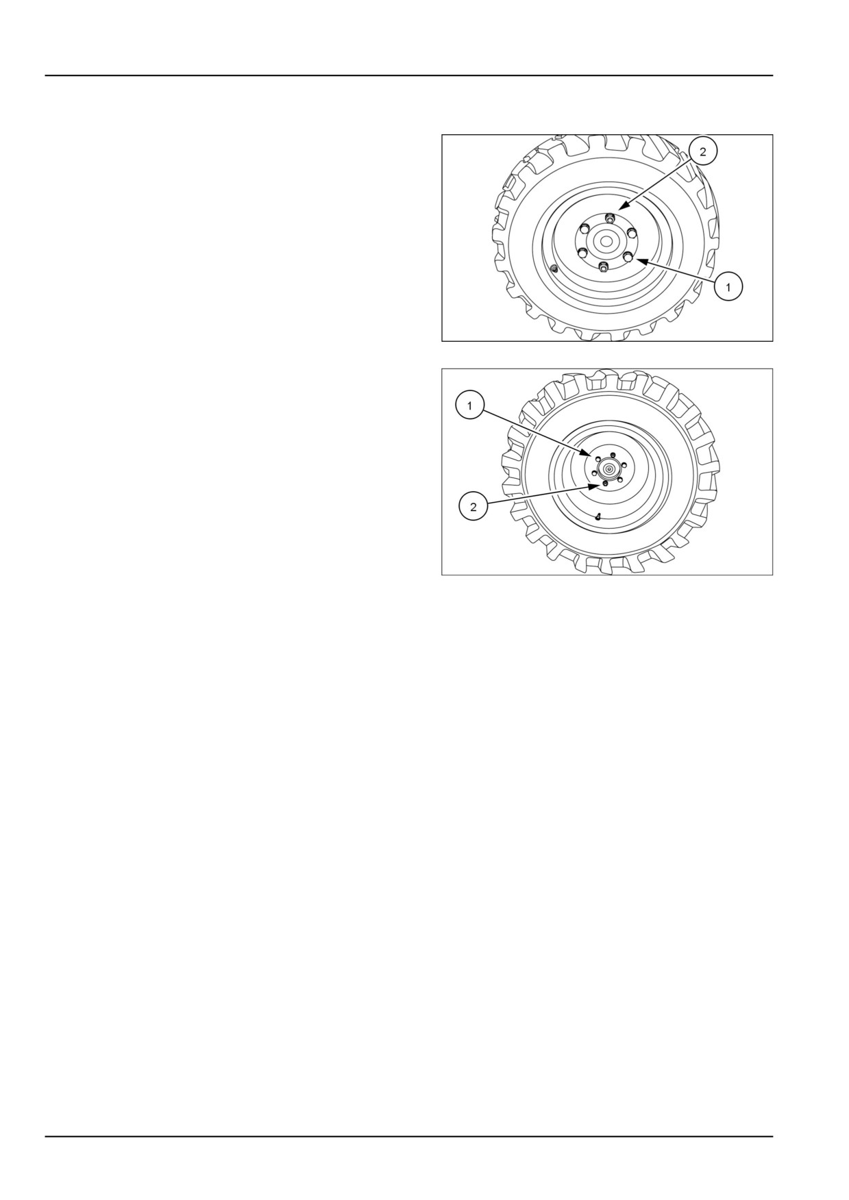
Front wheels - Tighten
Tighten the wheel bolts (1) and nuts (2) to the specified
torque any time the wheel assembly is removed from
the tractor or the wheel bolts are loosened.
Front Wheel Torque
•
176 - 196 N·m (130 - 145 lb ft)
93100874
1
Rear Wheel Torque
•
176 - 196 N·m (130 - 145 lb ft)
NOTICE: Check and tighten wheel bolts (1) and nuts (2)
to proper torque specifications after the following hours of
use:
• First 5 hours
• First 50 hours
• Every 250 hours
93100875A
2
7-36
7 - MAINTENANCE
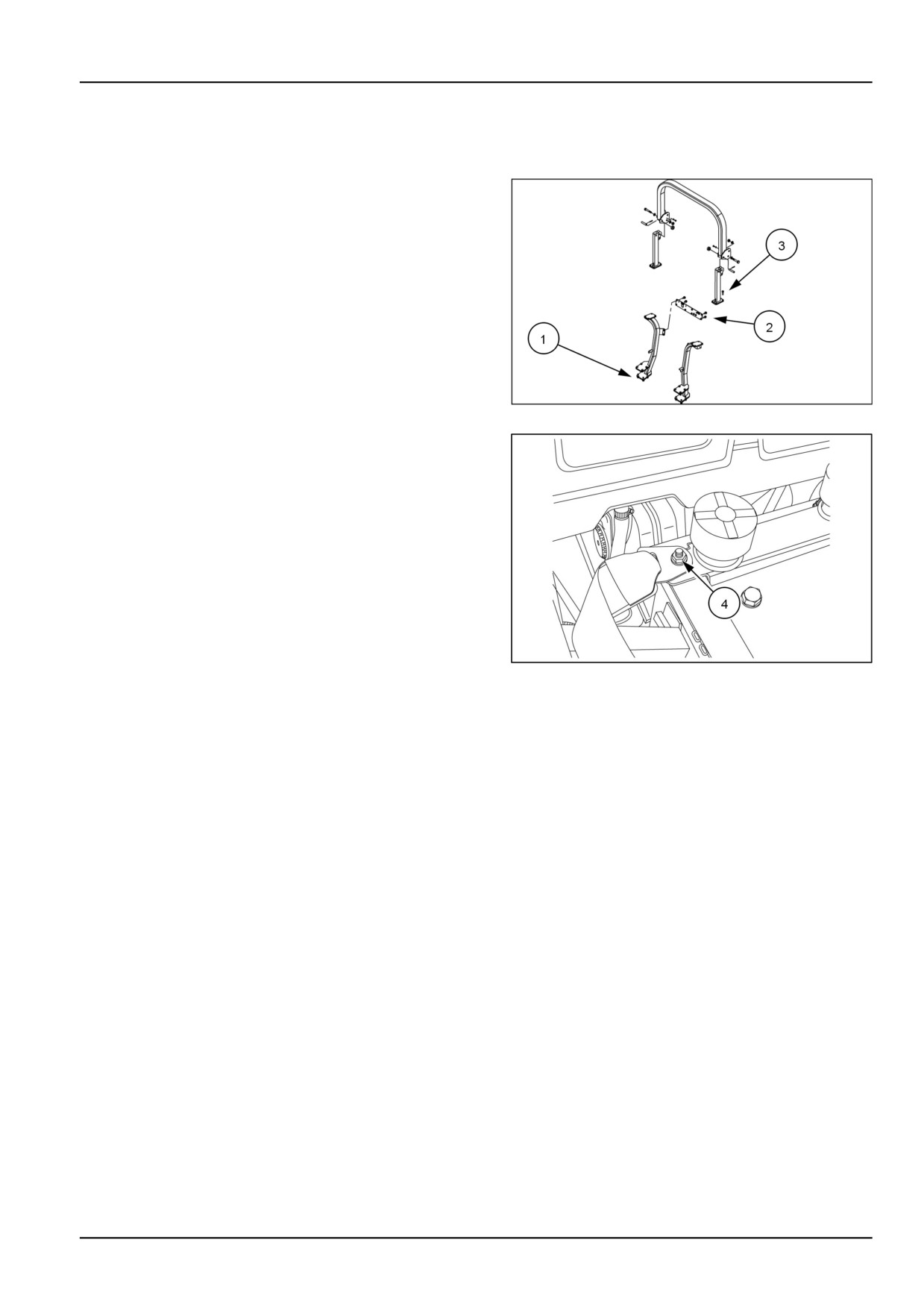
Roll Over Protective Structure (ROPS) frame - Check
Maintenance and inspection
1. Check the torque of the ROPS bottom portion mounting
bolts, (1). Tighten the M14, bolts to the correct torque
of 147 N·m (108 lb ft) if necessary.
2. Check the torque of the Roll Over Protective Structure
(ROPS) cross brace mounting bolts (2). Tighten the
M10 bolts to the correct torque of 60 N·m (41 lb ft) if
necessary.
3. Check the torque of the ROPS top portion mounting
bolts (3). Tighten the M12, bolts to the correct torque
of 83 N·m (61 lb ft) if necessary.
230100876
1
4. Inspect the operator's seat and the mounting parts for
the seat belt. Tighten the bolts (4) to the correct torque
of 28 N·m (21 lb ft) if necessary and replace any parts
that show wear or damage.
NHIL12CT00838AA
2
7-37
7 - MAINTENANCE
Every 500 hours
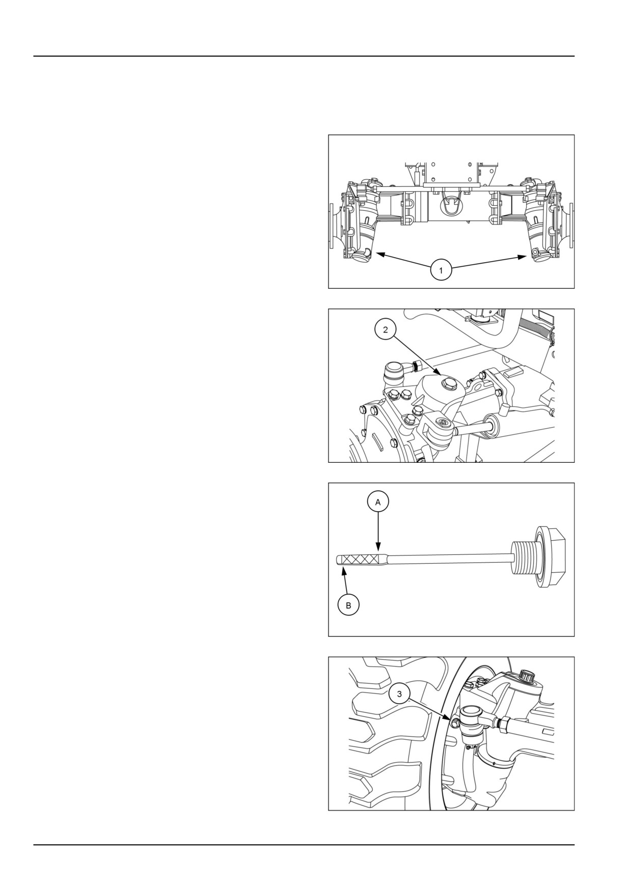
Front axle and differential fluid - Change
1. Place a suitable container beneath the oil plugs. With
the oil at normal operating temperature, drain the oil by
removing the drain plugs (1).
2. After the oil has drained, install the drain plugs and
discard the used oil.
93100868
1
3. Remove the dipstick/filler plug (2).
93100889
2
4. Fill the axle with HYPOID GEAR OIL EXTREME PRESSURE
80W-90 oil until the oil level is between the upper mark
(A), and the lower mark (B) of the dipstick. Reinstall
the dipstick/filler plug.
5. Raise the front axle until both wheels are off the ground.
6. Tilt axle until stops are contacted.
93100902
3
7. Slowly and momentarily remove plug (3) from the lower
side final drive housing. This will allow any air that
is trapped in the lower housing to escape, so that the
correct oil level can be achieved. Reinstall plug and tilt
axle the opposite direction. Repeat this procedure for
the other final drive housing.
8. Lower axle back to the ground.
9. Check the oil level at the dipstick, and add oil if needed
until the oil level is between the upper and lower marks
of dipstick.
10. After correct oil level is achieved, tighten all of the
drain plugs.
93110428
4
7-38
7 - MAINTENANCE
NOTE: Approximate fluid capacity for the front axle housing is 5.5 l (5.8 US qt).
7-39
7 - MAINTENANCE
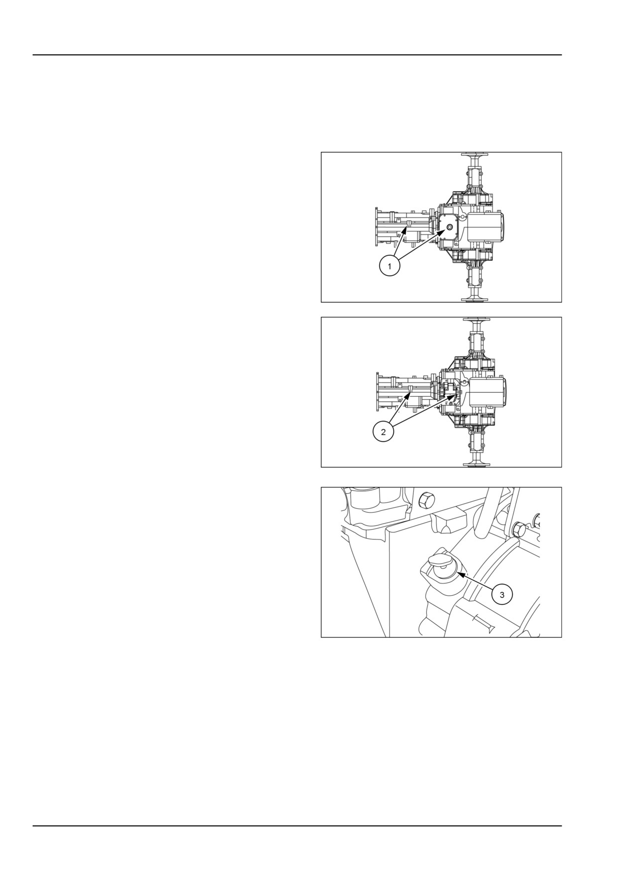
Transmission - Change fluid
NOTE: During cold weather operation, tractor hydraulic oil
can be changed to New Holland F200. The F200 oil is a
multi-viscosity oil which has improved flow characteristics
in low temperatures and can be used year round.
1. Place a suitable container beneath the transmission
plugs (1) (without Mid PTO) and (2) (With Mid PTO)
to catch the used oil.
2. With the oil at normal operating temperature, drain the
system by removing the transmission drain plugs.
3. Reinstall the plugs once the oil has drained.
4. Discard the used oil.
93100871
1
93100872
2
5. Remove the dipstick
(3) and fill with HYDRAULIC
TRANSMISSION OIL
- PREMIUM hydraulic oil. The
transmission is filled to the correct level when the oil
registers between the two marks on the dipstick.
Capacity:
• Mechanical transmission
30.0 l (7.9 US
gal)
• Hydrostatic transmission
30.0 l (7.9 US
gal)
6. Reinstall the dipstick .
NOTICE: There is a common sump for the transmission,
93099360
3
rear axle, and hydraulic system. Therefore, extra care
should be taken to keep the oil clean
7-40
7 - MAINTENANCE
Air cleaner - Inner element - Replace
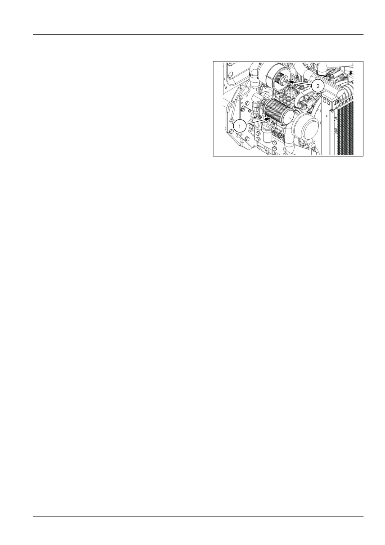
1. Pull the outer element (1) from the canister. Clean any
loose dirt from the canister and inspect the end of the
canister for dirt which may prevent the new element
from sealing properly.
2. Pull the inner element (2) from the canister
3. Install the new inner element by inserting it into the
canister and pushing on the end of the element until
it is seated against the canister.
4. Install the outer element by inserting it into the canister
and pushing on the end of the element until it is seated
against the canister.
NHIL17CT01804FA
1
NOTE: If element is not inserted far enough into canister,
the end cap cannot be installed.
5. Place the end cap onto the canister body, push in on
end cap, and rotate clockwise. Make sure the end cap
is locked in place and not loose.
NOTICE: Failure to obtain a good seal between elements
and the canister may cause major engine damage.
7-41
7 - MAINTENANCE
Valves - Check
Contact your NEW HOLLAND dealer to schedule this
service for your tractor.
7-42
7 - MAINTENANCE
Every two years
Engine cooling system - Drain fluid
Draining and flushing the cooling system
WARNING
Burn hazard!
Always remove the recovery tank cap BEFORE you remove the filler cap. Never remove either cap
while the engine is running or the coolant is hot. Stop the engine and let the system cool. Using a
thick cloth, loosen the cap slowly and allow the pressure to escape.
Failure to comply could result in death or serious injury.
W0361A
To drain the cooling system:
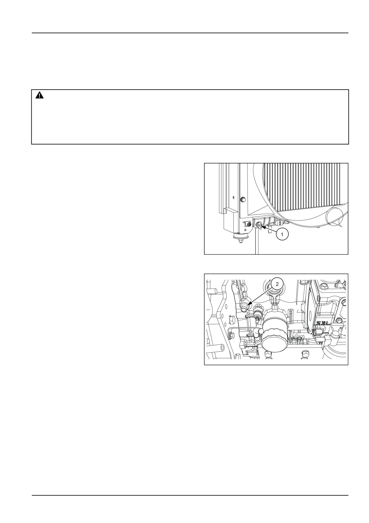
1.
Use a suitable receptacle to catch the used coolant.
2.
Remove the radiator cap and open the drain valve (1)
on the left-hand side of radiator to drain the coolant.
3.
After the coolant has drained, place a water hose in the
radiator filler neck and run water through the system.
4.
When water is flowing from the radiator drain valve,
start the engine.
5.
When the water flowing from drain valve is free from
coloration and sediment, stop the engine and remove
the hose. Allow all water to drain from the system
through the radiator drain valve.
NHIL12CT00827AA
1
6.
Close the radiator drain valve.
7.
Remove the engine block coolant drain plug (2). This
plug is located to the right-hand side of the engine near
the clutch housing.
8.
Allow all the water to drain from the engine block.
9.
Install the engine block coolant drain plug.
10. Slowly refill the system with a 50/50 solution IAT
COOLANT 11 - CLASSIC and water. Fill until the coolant
level is even with the bottom of the filler neck. Do not
fill beyond this level.
11. Clean the radiator cap and reinstall the cap.
12. Run the engine until normal operating temperature is
NHIL17CT01805AA
2
reached, then stop the engine.
13. Recheck the coolant level when the engine is cold and
add additional coolant as necessary.
NOTICE: Never run the engine when the cooling system is
empty. Do not add cold water or cold antifreeze solution if
the engine is hot.
NOTE: OAT EXTENDED LIFE COOLANT/ANTIFREEZE is an
approved optional long life coolant. See page 7-7 for use
of optional coolant.
7-43
7 - MAINTENANCE
As required
Fuel injection system - Bleed
WARNING
Escaping fluid!
Hydraulic fluid or diesel fuel leaking under pressure can penetrate the skin and cause infection or
other injury. To prevent personal injury: Relieve all pressure before disconnecting fluid lines or per-
forming work on the hydraulic system. Before applying pressure, make sure all connections are tight
and all components are in good condition. Never use your hand to check for suspected leaks under
pressure. Use a piece of cardboard or wood for this purpose.
If
injured by leaking fluid, see your
doctor immediately.
Failure to comply could result in death or serious injury.
W0178A
Bleed the fuel system if:
• It has been drained.
• A new filter element has been installed.
• The tractor has run out of fuel.
• The lines leading to or from the filter have been dis-
connected.
• The injection pump has been removed and rein-
stalled.
To bleed the fuel system:
1. Make sure there is adequate fuel in the fuel tank.
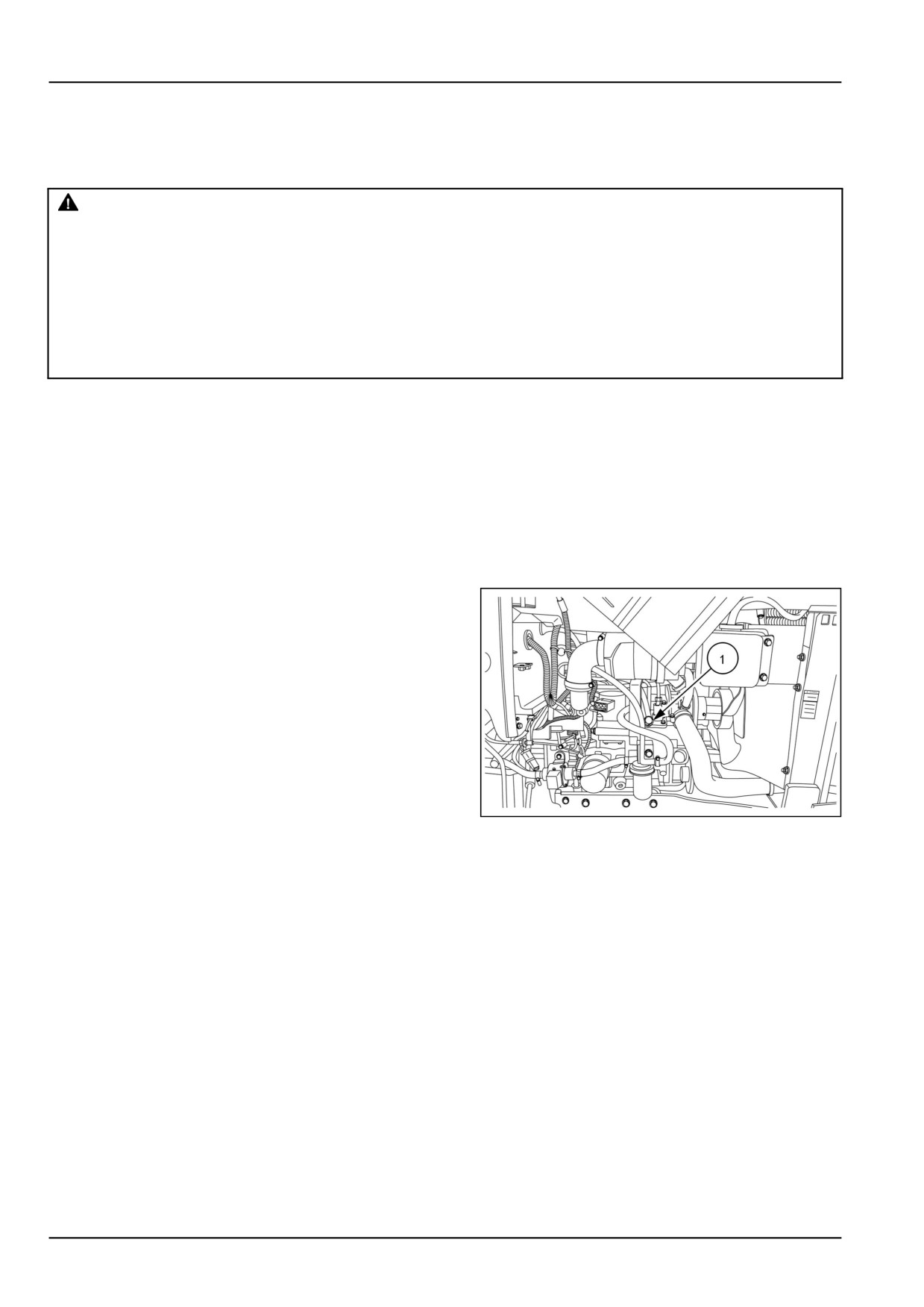
2. Loosen the air-bleed bolt (1) from the fuel injection
pump.
3. Turn the key to the “ON” position.
4. Tighten the air-bleed bolt once the fuel flowing from
the air-bleed bolt is free of air bubbles.
5. Torque the air-bleed bolt to 8.0 N·m (70.8 lb in).
6. Advance the hand throttle lever to the half-throttle
position.
7. Start the tractor and check for fuel leaks.
NHIL17CT01441AA
1
8. If the tractor fails to start or starts then shuts off
perform the bleed procedure again..
NOTE: Please contact your NEW HOLLAND
dealer if you have any problems or questions
concerning this procedure.
7-44
7 - MAINTENANCE
Roll Over Protective Structure (ROPS) frame - Replace - Possible
damage
WARNING
Roll-over hazard!
Always pull from the drawbar. DO NOT attach chains or ropes to the Roll Over Protective Structure
(ROPS) for pulling purposes, as the machine could tip over. When driving through door openings or
under low overhead objects, make sure there is sufficient clearance for the ROPS.
Failure to comply could result in death or serious injury.
W0463A
WARNING
Equipment failure could cause accident or injury!
The Roll Over Protective Structure (ROPS) and interconnecting components are a certified system.
Make sure you tighten the ROPS mounting bolts to the required torque specification.
Failure to comply could result in death or serious injury.
W0935A
WARNING
Crushing hazard!
Always wear the seat belt when operating the machine with the Roll Over Protective Structure (ROPS)
in the upright position. If the ROPS is in the folded position, the seat belt should not be used. Raise
the ROPS and wear the seat belt as soon as conditions allow.
Failure to comply could result in death or serious injury.
W0462A
If the unit has rolled over or the ROPS has been in some
other type of accident (such as hitting an overhead ob-
ject during transport), the ROPS must be replaced to
retain the best protection.
Following an accident, check the ROPS, the operator's
seat, and the seat belt and seat belt mountings for pos-
sible damage. Before operating the machine, replace
all damaged parts.
NOTICE: Do not attempt to weld or straighten the ROPS.
7-45