New Holland Workmaster 25, Tier 4B (final) Compact Tractor. OPERATOR’S MANUAL (2020) - page 5
7 - MAINTENANCE
Battery - Test
WARNING
Explosion hazard!
If battery electrolyte is frozen, attempting to charge the battery or jump-start the engine can cause the
battery to explode. Always keep batteries at full charge to prevent frozen battery electrolyte. Never
charge a frozen battery.
Failure to comply could result in death or serious injury.
W0203A
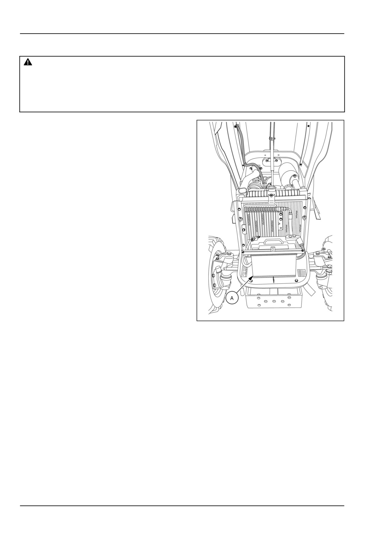
The tractor is equipped with a BCI group 34, 12 V bat-
tery (A) with a minimum cold cranking ability of 660 A
at -18 °C (0 °F).
Make sure the battery connections are tight and free
of corrosion. A solution of baking soda and water may
be used to wash the outside surface and terminals of
the battery when necessary. However, make sure the
solution does not get inside the battery. After cleaning,
wash the battery with clean water, then apply a small
amount of petroleum jelly to the terminals to prevent
corrosion.
In freezing temperatures, a good battery charge must
be maintained. If the battery becomes discharged
or run down, the electrolyte becomes weak and may
freeze, causing damage to the case. If you must add
water, use distilled water. Add the water just before
using the tractor so that the water will mix with the elec-
trolyte during the charging process, thus preventing
the water from freezing.
To determine the battery charge, check the specific
gravity of the electrolyte.
NHIL17CT01425BA
1
7-46
7 - MAINTENANCE
Fuses - Check
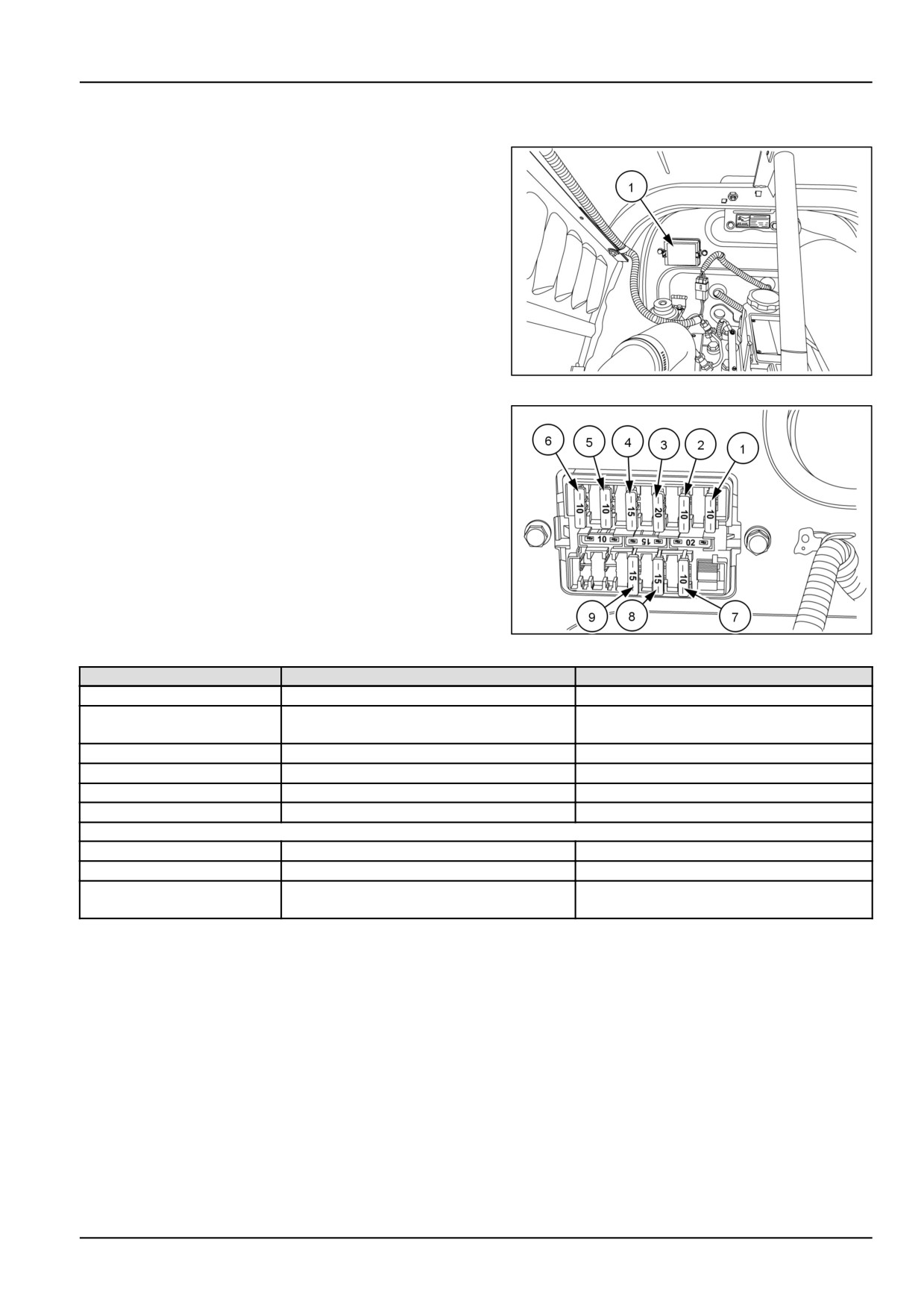
The fuse block (1) is located on the right-hand side of
the engine firewall. Always replace blown fuses with
the size specified for that circuit.
NHIL12CT00676AA
1
From right to left the fuse block contains the following
fuses:
2
NHIL12CT00685AA
Fuse #
Fuse Size
Circuit Protected
1
10 A
Engine, Alternator
2
10 A
Instrument panel, Glow plugs relay, Horn,
Brake lights
3
20 A
Head lights relay
4
15 A
Rear work light (optional )
5
10 A
PTO
6
10 A
Safety controller
Bottom Row
7
10 A
Spare
8
15 A
Turn signals
9
15 A
Hazard lights, Headlights switch, Position
lights
7-47
7 - MAINTENANCE
Main fuse - Check
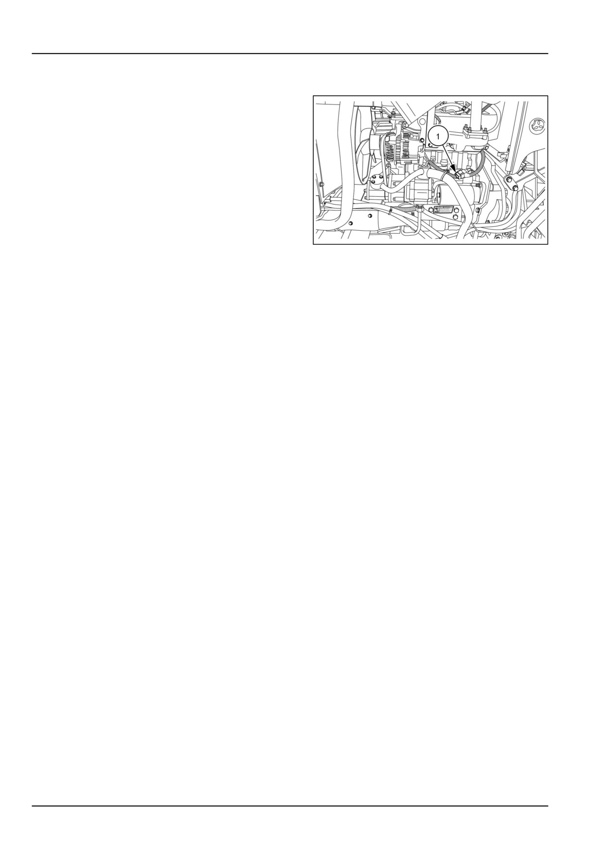
The main fuse (1) is a 50 A fuse and it is located on the
left-hand side of the engine and positioned above the
stater. This fuse protects the tractor's entire electrical
system.
NHIL17CT01442AA
1
To replace the main fuse:
1. Remove the old fuse from the fuse holder and replace.
NOTICE: Always replace this fuse with a 50 A fuse; DO
NOT increase amperage rating.
7-48
7 - MAINTENANCE
Headlight - Replace
If head lamps, fail to operate, the bulb must be replaced.
To change the bulb:
1. Open the tractor hood.
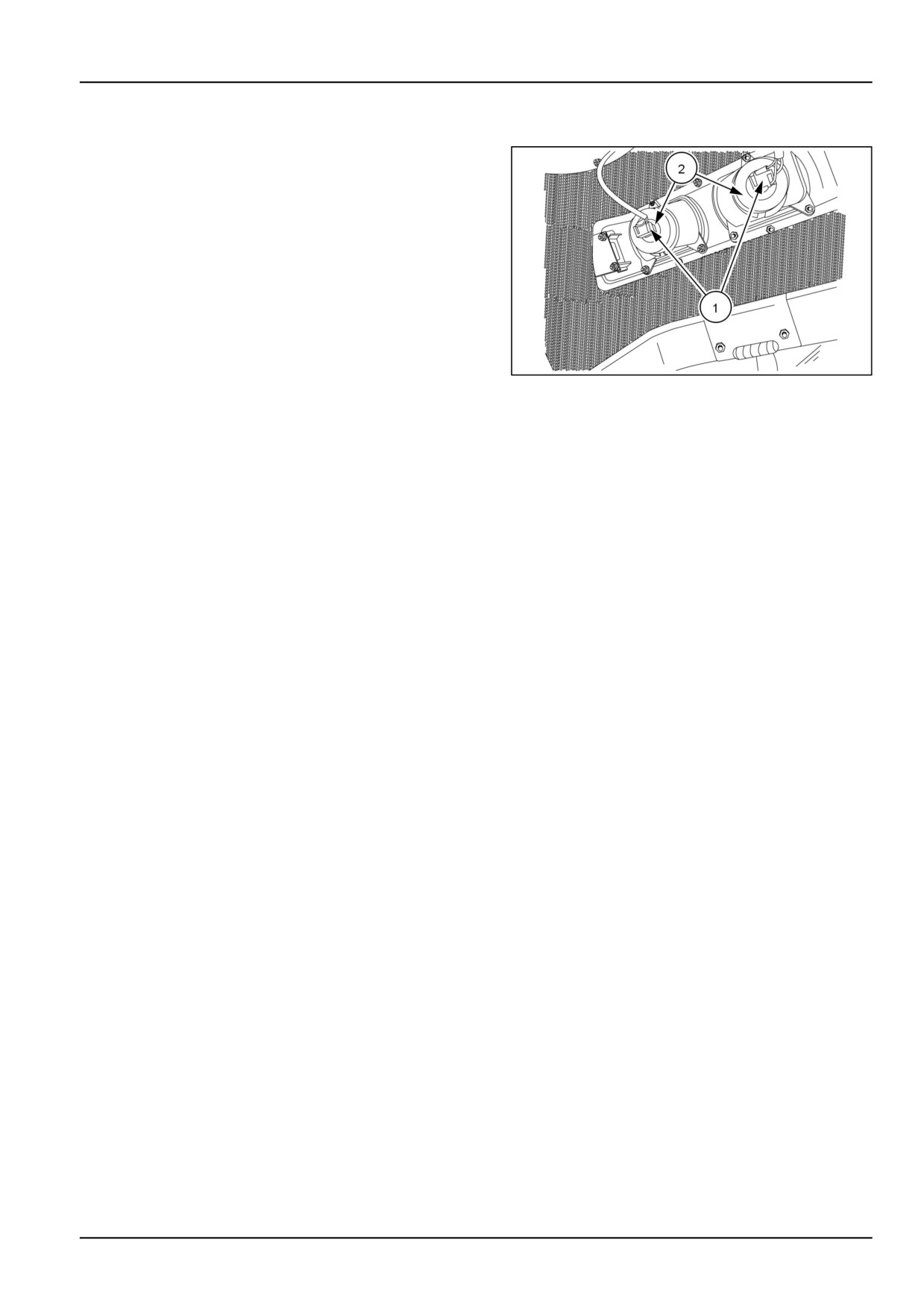
2. Disconnect wire harness connector (1) from the head-
light bulb.
3. Remove rubber boot (2) to reveal headlight retainer.
4. Release the two tabs that retain the bulb to the housing.
5. Remove the bulb from the housing. .
6. Place a new bulb in the housing, then reinstall the re-
tainer in the housing.
NHIL12CT00834AA
1
NOTICE: Be careful not to touch the bulb with bare fingers.
Oil from the fingers can shorten the life of bulb. Use pro-
tective cloth or glove when installing bulb.
NOTE: Replacement bulbs are dual 55/60 W filament halo-
gen : (H4 U 37R).
7. Reinstall rubber boot and wire harness connector.
7-49
7 - MAINTENANCE
Tail light and brake light bulb - Replace
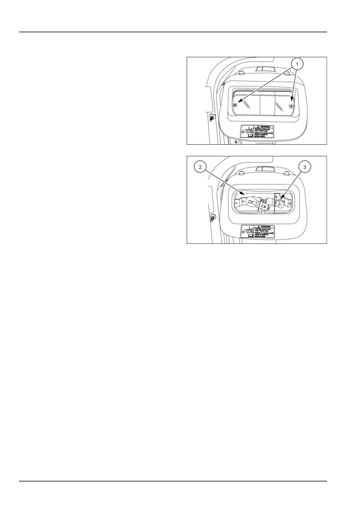
To replace a taillight bulb:
1. Remove the two screws (1) retaining the taillight lens
and remove the lens.
93100887
1
2. Push in on the brake/tail light bulb (2) or turn signal
bulb (3) and rotate counter-clockwise in the socket to
remove the old bulb.
3. Insert the new bulb into the socket and turn the bulb in
a clockwise direction until tightened.
NOTE: Replace brake/tail bulb with a P21/5 watt bulb. and
turn signal bulb with a R10 watt bulb
93100888
2
7-50
7 - MAINTENANCE
Turn signal and hazard bulb - Replace
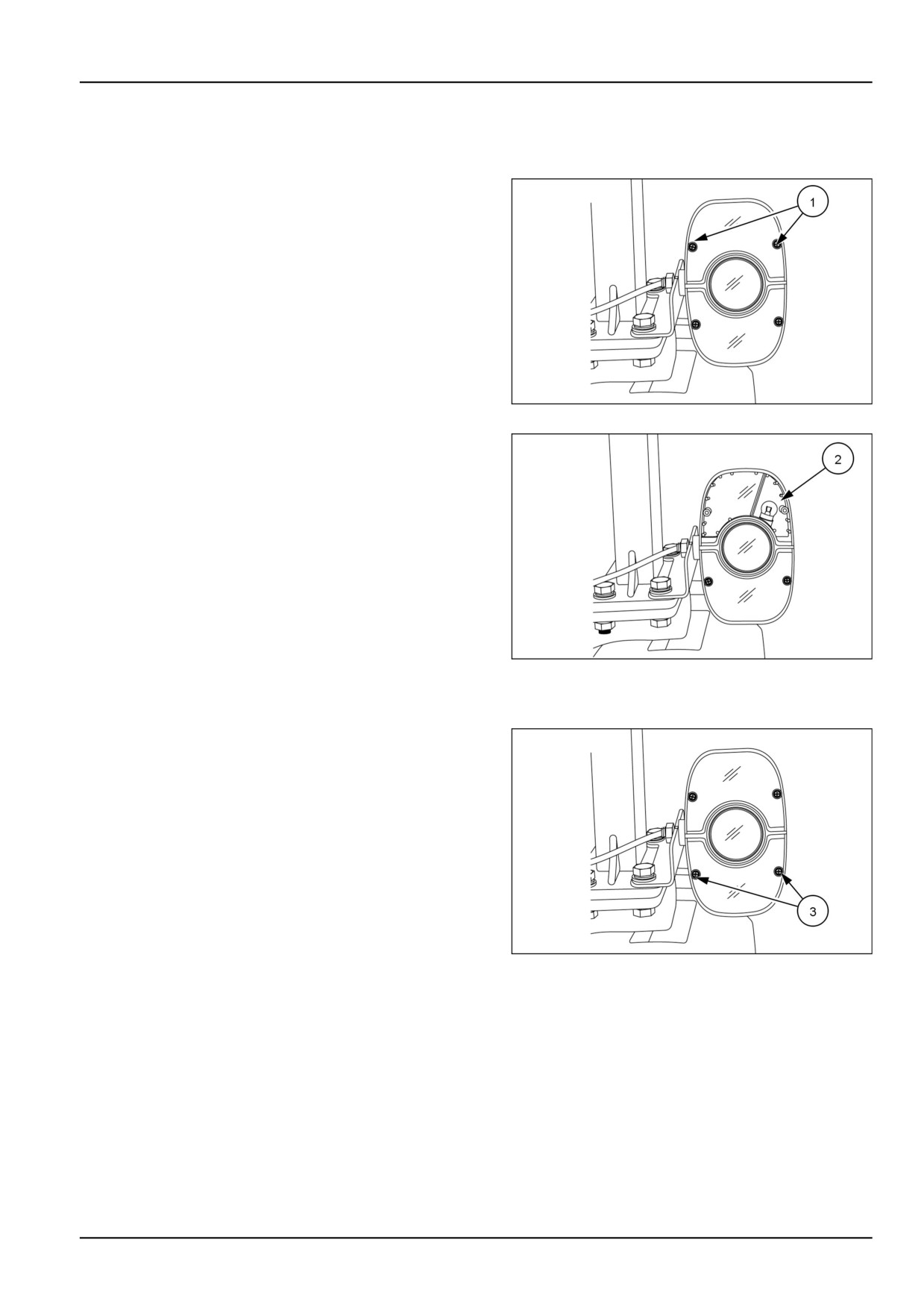
To replace the top flasher light bulb:
1. Remove the two screws (1) retaining the top flasher
light lenses and remove the lenses.
93100885
1
2. Push in on the bulb (2) and rotate bulb counter-clock-
wise in socket to remove.
NOTE: Replace with a P21 watt bulb.
3. Insert the new bulb into the socket and turn it clockwise
until the bulb locks into place.
4. Install lenses and retaining screws.
93100894
2
To replace the bottom flasher light bulb:
5. Remove the two screws (3) retaining the top flasher
light lenses and remove the lenses.
93100885
3
7-51
7 - MAINTENANCE
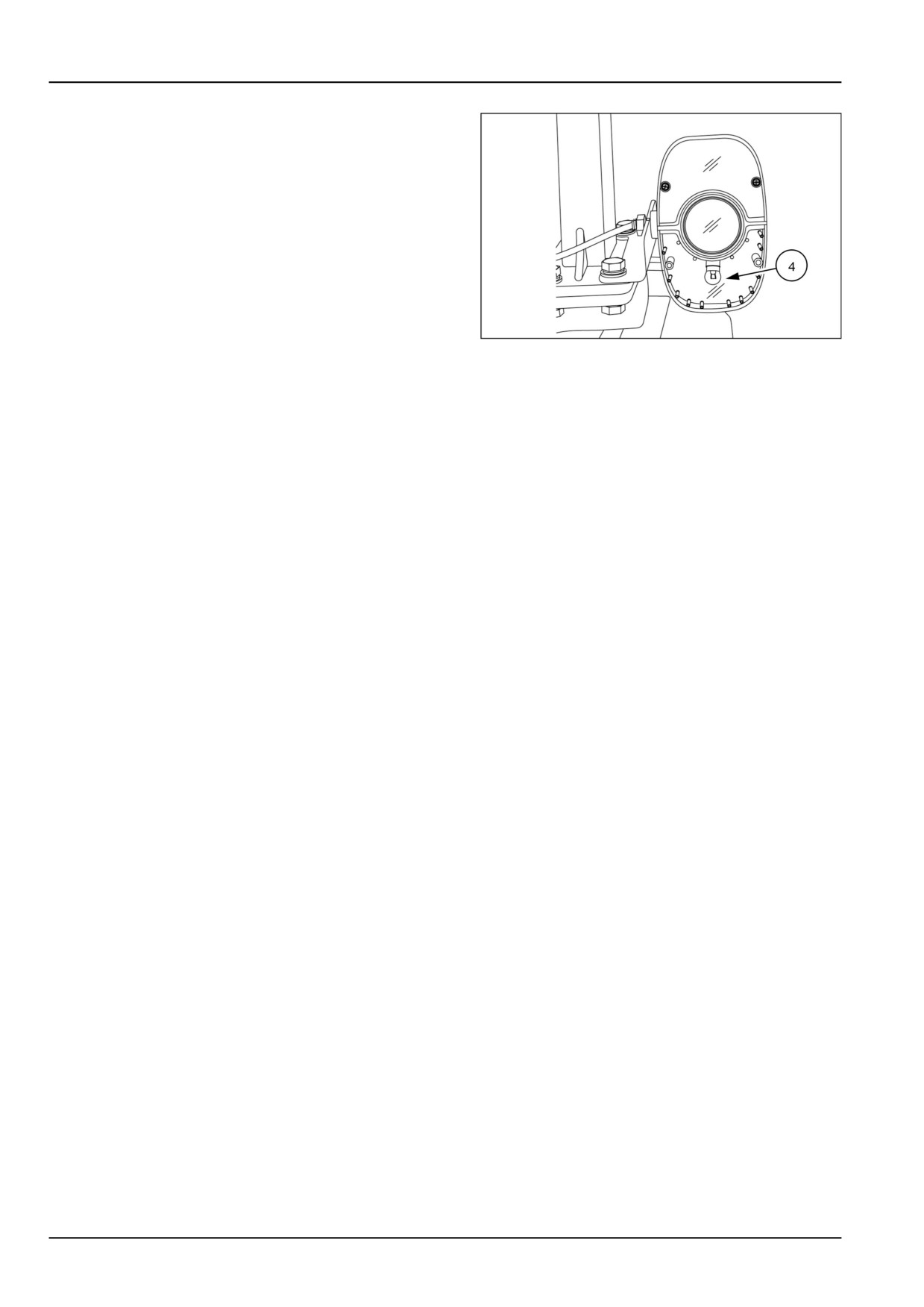
6. Push in on the bulb (4) and rotate bulb counter-clock-
wise in socket to remove.
NOTE: Replace with a R10 watt bulb.
7. Insert the new bulb into the socket and turn it clockwise
until the bulb locks into place.
8. Install lenses and retaining screws.
93100886
4
7-52
7 - MAINTENANCE
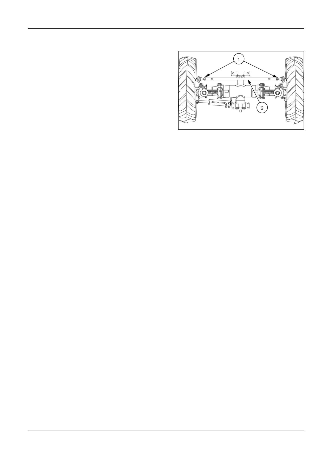
Front wheels toe-in - Check
If toe-in is not correct, adjust as follows:
1. Loosen the tie rod locknuts (1).
2. Adjust the tie rod tube assembly (2) as required to give
0 - 5 mm (0 - 0.2 in) toe-in.
3. After the correct toe-in is obtained, tighten the tie rod
locknuts.
93100867
1
7-53
7 - MAINTENANCE
Belt - Adjust
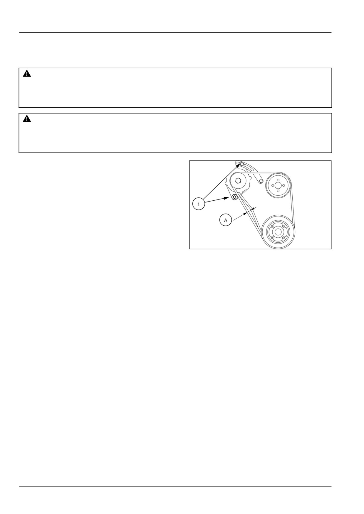
To adjust fan belt tension:
WARNING
Maintenance hazard!
The engine must be OFF when you loosen or tighten alternator mounting bolts.
Failure to comply could result in death or serious injury.
W1096A
WARNING
Rotating parts!
The engine is running. Keep clear of rotating fans and belts.
Failure to comply could result in death or serious injury.
W0275A
1. Loosen the alternator mounting bolts (1).
2. Pry the alternator away from the engine and tighten the
mounting bolts.
3. Recheck belt deflection (A). When 10 kg (22 lb) of
pressure is applied midway between the belt pulleys,
a correctly tightened belt will deflect 10 - 12 mm (0.4
- 0.5 in).
93100870
1
7-54
7 - MAINTENANCE
Storage
Storing the tractor
Below is a list of protective measures which should be
taken if your tractor is to be stored for an extended pe-
riod of time:
1. Thoroughly clean the tractor. Use touch up paint where
necessary to prevent rust.
2. Check the tractor for worn or damaged parts. Install
new parts as required.
3. Raise the lift arms hydraulically to their fullest raised
position so that the lift piston is in a fully extended po-
sition. This fills the cylinder with oil and protects the
cylinder wall surfaces from corrosion.
4. Lubricate the tractor.
5. Fill the fuel tank with No. 1 diesel fuel.
NOTICE: Do not use No. 2 diesel fuel for winter storage
because of wax separation and setting at low temperature.
6. Open the drain valve of the radiator and engine block.
Flush the system, close the drain valves, and fill with a
50/50 solution of permanent antifreeze and clear water.
7. Remove the battery and clean it thoroughly. Be sure
that it is fully charged and that the electrolyte is at the
proper level. Store the battery in a cool, dry place
above freezing temperature, and charge it periodically
during storage.
8. Place blocking under the tractor axles to remove the
weight from the tires.
9. Cover the exhaust pipe opening.
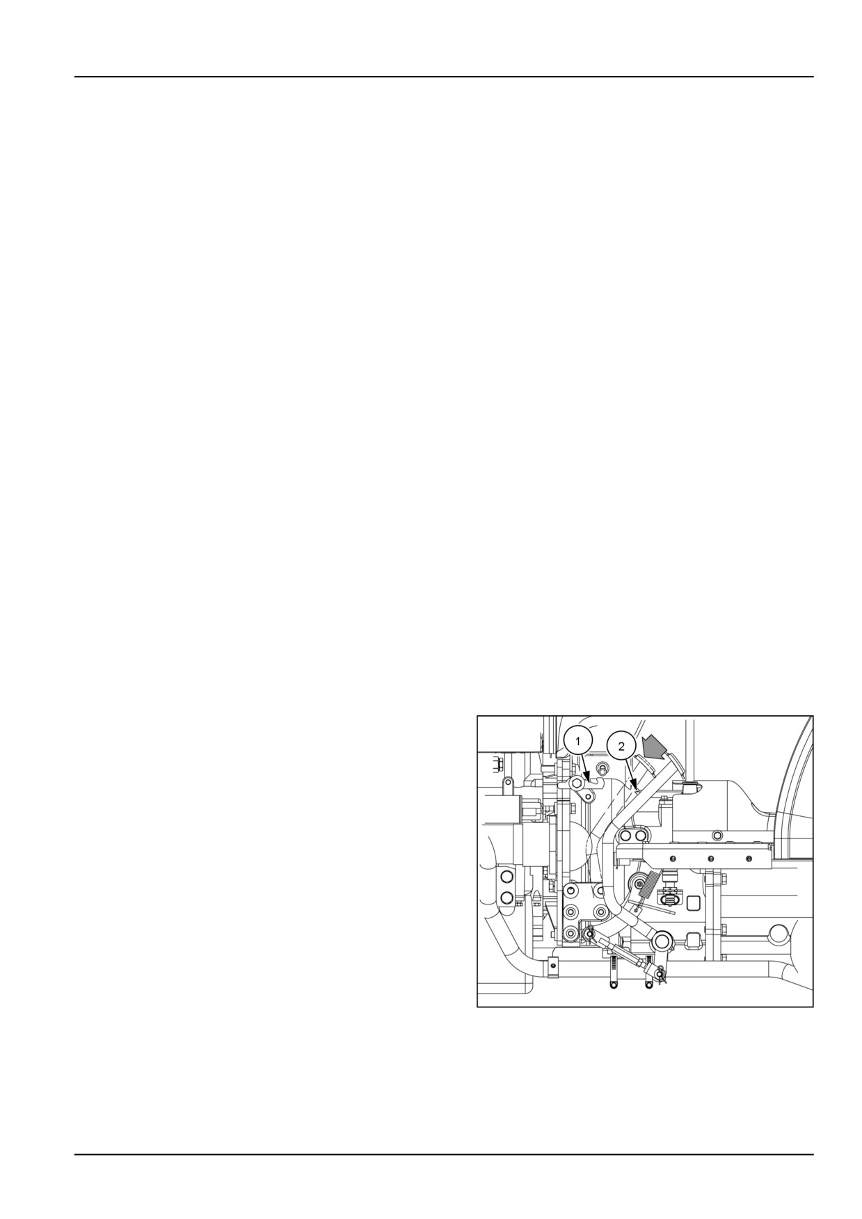
10. Depress the clutch pedal, engage the latch (1) with the
pin (2) located on the clutch pedal. When the clutch
pedal is locked in this position, the clutch disc will be
separated from the flywheel.
NHIL12CT00828AA
1
7-55
7 - MAINTENANCE
Removing the tractor from storage
Tractors which have been placed in storage should be
completely serviced in the following manner before us-
ing:
1. Inflate the tires to the recommended pressures and re-
move the blocking.
2. Check the oil level in the engine crankcase, power
steering reservoir, the common sump (for the hydraulic
lift, transmission, and rear axle), and the optional front-
wheel drive axle.
3. Install a fully charged battery and remove the exhaust
cover if other than a rain cap.
4. Check the cooling system for the proper level (50/50
solution of antifreeze and clear water).
5. Start the engine and allow it to idle a few minutes. En-
sure the engine is receiving lubrication and that each
control is functioning correctly.
6. Drive the tractor without a load and check to make sure
it is operating satisfactorily.
Touch-up paint
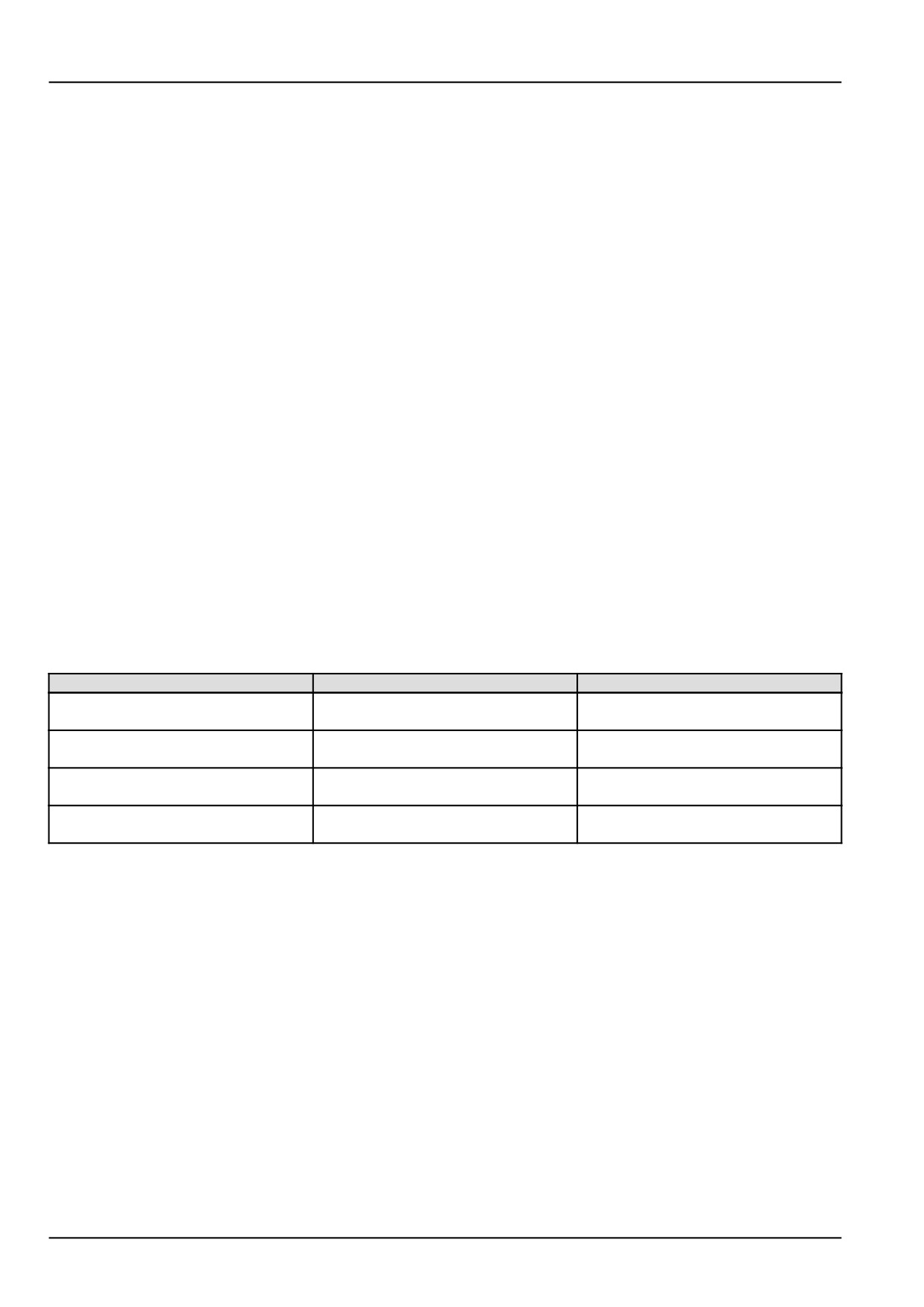
The following New Holland paints are recommended for
touch-up paint repairs.
Color
Part No.
Amount
86109144-DS
16 oz Spray
New Holland Bright Blue
86109141-DS
1 US qt
B96104
16 oz Spray
CNH Dark Gray
B96105
1 US qt
9624698-DS
16 oz Spray
Bianco White (Wheels)
9624699-DS
1 US qt
94792-DS
16 oz Spray
Med Gloss Black
9624700-DS
1 US qt
7-56
8 - TROUBLESHOOTING
8 - TROUBLESHOOTING###_8_###
Symptom(s)
Troubleshooting - Foreword
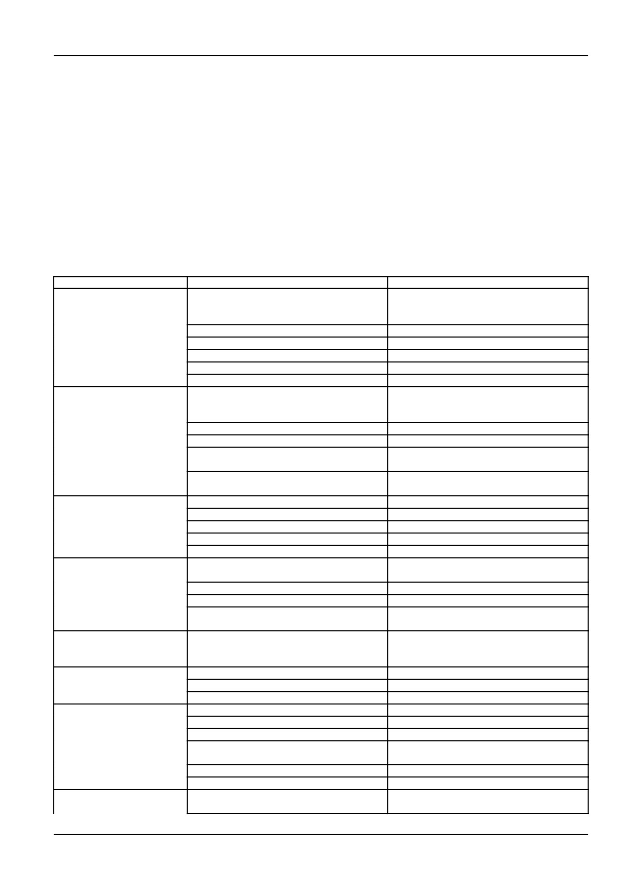
The following troubleshooting information will help you in the unlikely event a problem occurs with your equipment.
Reading the troubleshooting chart is easy. The left-hand column will be the problem you may be having with your
equipment. The center column explains the possible cause or causes of the problem. The right-hand columns gives
you corrective actions you can take to solve the problem. If you feel unsure how to handle the problem with your
equipment do not hesitate to contact your NEW HOLLAND dealer for assistance.
Engine - Troubleshooting
Problem
Possible Cause
Correction
The start motor does not
Low battery charge
Charge or replace
rotate with the key switch
in the (START) position.
Loose battery or starter cable terminals
Tighten the terminal
Key switch faulty
Repair or replace switch
Safety start switch not completing circuit
Depress clutch pedal fully
PTO safety switch is not in "OFF" position
Place PTO switch in "OFF" position
Starter motor faulty
Repair or replace starter motor
The start motor rotates
Low battery charge
Charge or replace battery
but the engine does not
start
Air in fuel system
Bleed out the air
Fuel filter clogged
Clean or replace the filter
Fuel shutoff valve on fuel filter in closed
Open the valve
position
Fuel shutoff solenoid on fuel injection pump
Check solenoid for proper operation, repair
stuck in off position
as needed
Engine speed is irregular
Air in fuel system
Bleed the fuel system
Fuel filter clogged
Clean or replace the filter
Injection nozzle clogged
Repair or replace nozzle
Fuel leakage
Repair fuel system
Irregular fuel injection
Repair or replace fuel injection pump
Engine stops suddenly
Fuel shortage
Add fuel and bleed air from fuel system
during operation
Faulty fuel injector
Repair or replace injector
Faulty fuel injection pump
Repair or replace injection pump
Internal parts of engine seized due to lack
Repair engine as needed
of lubrication
Engine speed is more
Fault with the engine speed control unit.
See your NEW HOLLAND dealer for ser-
than maximum rated high
vice.
idle speed
Engine stops at low speed
Faulty injection pump
Repair or replace injection pump as needed
Engine valve gap is not correct
Adjust the gap
Low fuel injector pressure
Repair fuel injector as needed
Low engine power
Fuel injector nozzle clogged
Repair injector as needed
Carbon accumulation on valve seat
Repair valve and seats as needed
Incorrect valve gap adjustment
Adjust valve gap to correct amount
Incorrect fuel injection timing
Check and adjust fuel injection timing as
needed
Lack of fuel supply
Check fuel system for restriction
Air filter clogged
Clean or replace air filter
The color of exhaust
Low engine operating temperature
Allow engine to obtain higher operating
smoke is white
temperature
8-1
8 - TROUBLESHOOTING
Problem
Possible Cause
Correction
Engine burning engine oil
Repair engine as needed
Engine coolant entering engine exhaust
Repair engine as needed
The color of exhaust gas
Air filter clogged
Clean or replace engine air filter
is black.
Excessive fuel supply
Repair fuel injection pump as needed
Faulty fuel injector
Repair or replace fuel injector
Instrument panel engine
Lack of engine oil
Add engine oil as needed
oil pressure indicator light
is "ON" during operation.
Low viscosity of engine oil
Replace oil with proper viscosity type
Faulty pressure switch
Replace switch
Faulty engine oil pump
Repair oil pump as needed
Engine oil filter clogged
Replace the filter
Instrument panel battery
Bad electrical connection
Check battery terminals, ground, and repair
charging indicator is "ON"
as needed
during operation.
Faulty alternator
Repair or replace alternator as needed
Faulty battery
Replace battery
Incorrect fan belt tension or belt broken
Adjust belt tension or replace belt
Engine fault icon is
Electrical fault with the engine speed con-
See your NEW HOLLAND dealer for ser-
illuminated on the
trol unit.
vice.
instrument panel.
Engine overheating
Lack of coolant
Add coolant as needed
Fan belt slipping or belt is broken
Adjust belt tension or replace belt
Dirt attached to the radiator or prescreen
Clean radiator fins or screen as needed
Clutch - Troubleshooting
Problem
Possible Cause
Correction
Clutch slips
Incorrect adjustment of clutch pedal free
Adjust the pedal free play correctly
play
Clutch disc lining worn or broken
Replace clutch disc
Clutch does not release
Excessive clutch pedal free play
Adjust the pedal free play
Clutch disc damaged
Repair or replace clutch disc
Mechanical service brakes - Troubleshooting
Problem
Possible Cause
Correction
After engaging brake
Return spring damaged
Replace the spring
pedal, pedal will not
return
Lack of lubrication in brake shaft linkage
Clean and lubricate linkage as needed
parts
Damaged internal brake parts
Repair internal brake parts as needed
Brake does not work or
Incorrect brake pedal free play
Adjust brake pedal free play to correct
only one side works.
specification
Brake disc lining worn or broken
Replace brake discs as needed
Left/right pedal free play is different
Adjust both brake pedal free play to same
specification
Regulated/Low pressure system - Troubleshooting
Problem
Possible Cause
Correction
The three-point linkage
Lack of transmission / hydraulic oil
Add oil as needed
will not raise
Air in the hydraulic suction pipe
Tighten the hydraulic filter and check all hy-
draulic suction connections
Hydraulic filter clogged
Replace hydraulic filter
8-2
8 - TROUBLESHOOTING
Problem
Possible Cause
Correction
Faulty hydraulic pump
Check pump for proper flow replace pump
if needed
Faulty control valve
Check hydraulic control valve and linkage
for proper operation repair as needed
Faulty hydraulic lift cylinder
Repair lift cylinder as needed
Faulty hydraulic relief valve
Check hydraulic system for correct pres-
sure setting, repair as needed
The three-point linkage
Down speed control valve locked in closed
Turn the knob counterclockwise, to open
does not move down
position
valve
when control handle is
moved to down position.
Control valve failure
Repair or replace valve
Hydraulic lift cylinder damaged
Repair cylinder as needed
Lift shaft moving parts damaged
Repair or replace lift shaft parts as needed
Oil leakage
Connecting part loosened
Tighten
Oil seal damaged
Replace
Pipe cracked
Replace
If lever is placed on
Incorrect upper limit of position control lever
Adjust the upper limit of position control
raising position, relief
lever
valve sounds off.
Steering - Troubleshooting
Problem
Possible Cause
Correction
Hydraulic steering system
Faulty power steering pump
Replace pump if needed
does not work
Steering unit damaged or worn
Repair or replace unit as needed
Steering cylinder piston seal damaged or
Repair cylinder as needed
worn
External oil leakage of oil tubes or hoses
Repair or replace tubes or hoses as
needed
Excessive steering wheel
Steering unit: Spline and column spline
Check mounted condition of steering unit
effort
does not align
and column
Steering unit: Spool and sleeve damaged
Replace steering unit
by foreign material
Steering unit: Excessive tightening torque
Apply proper torque of end cap hardware
of end cap bolt
Pump: Low flow
Increase engine RPM, to increase pump
flow
Faulty power steering pump
Check pump , repair or replace if needed
Power steering relief valve: pressure set-
Check power steering relief valve pressure
ting low
adjust to proper pressure setting
Cylinder movement not as
Air in steering line if not used for a long time
Bleed air in steering system
smooth as steering wheel
Air in suction tube
Check suction tube, repair as needed
Cylinder piston seal damaged
Repair cylinder as needed
Front wheels turn the
Incorrect assembly of steering gear
Repair steering gear as needed
opposite direction to the
steering wheel direction
Incorrect assembly of steering hoses
Assemble steering hoses correctly
Oil leakage of steering
Seal damaged
Replace seal
pump, steering unit,
cylinder
Abnormal noise
Lack of oil
Add oil as needed
Restriction of oil flow in suction line
Replace filter
Air in system
Bleed air from system
8-3
8 - TROUBLESHOOTING
Hydrostatic transmission - Troubleshooting
Problem
Possible Cause
Correction
When operating HST
HST high pressure relief valve pressure
Check HST pressure and repair as needed
pedal, tractor does not
setting low
move.
HST charge pressure valve faulty
Check HST charge pressure and repair as
needed
HST Filter clogged
Replace HST filter
HST pump faulty
Repair or replace HST pump
HST control linkage worn or damaged
Repair or replace linkage as needed
Tractor is still moving
Incorrect neutral adjustment of HST linkage
Adjust neutral position of HST linkage
when HST pedal is in
neutral position
HST pedal linkage damaged
Replace damaged linkage parts as needed
HST control arm clamp bolt loose
Tighten control arm clamp bolt
HST power is low
Oil shortage
Add transmission oil as needed
Air in HST circuit
Check and repair the hydraulic suction line
Transmission oil temperature is too high
Shut down tractor to cool the transmission
oil, and restart after oil temperature has
been reduced
HST internal parts worn
Repair HST transmission as needed
HST filter clogged
Replace the HST filter
Abnormal noise
Engine speed is too low
Set engine speed over 1500 RPM
Oil temperature is too low
Run engine to warm up the oil
HST oil filter clogged
Replace the HST filter
Oil shortage
Add transmission oil as needed
Electrical system - Troubleshooting
Problem
Possible Cause
Correction
Headlights are dim
Battery charge is low
Charge or replace battery
Faulty headlight wiring or
faulty ground
Check and repair wiring as needed
connection
Battery does not charge
Incorrect wiring
Check battery terminals and ground for cor-
rosion
Faulty Alternator
Test alternator repair or replace as needed
Incorrect fan belt tension or broken belt
Adjust fan belt tension or replace belt
Faulty battery
Replace battery
Headlights will not
Light bulb burnt out
Replace bulb as needed
illuminate
Blown Fuse
Check the cause and replace fuse with cor-
rect size
Faulty wiring connection
Check headlight wiring connection, repair
as needed
Faulty light switch
Check switch for proper function and re-
place if needed
Horn does not sound
Horn switch failure
Replace horn switch
Faulty wiring connection
Check horn wiring connection, repair as
needed
Blown fuse
Check for cause, replace fuse with correct
size
Faulty horn
Check horn , replace if needed
Turn signal lights do not
Light bulb burnt out
Replace bulb, with correct size
work
Faulty wiring connection
Check wiring connections, repair as
needed
Blown fuse
Check the cause, replace fuse with correct
size
Faulty turn signal switch
Check switch for proper function, replace
switch if needed
8-4

8 - TROUBLESHOOTING
Problem
Possible Cause
Correction
Cold start aid not working
Faulty connection of glow plug wiring
Check and repair glow plug wiring as
needed.
Blown fuse
Check for cause and replace fuse with cor-
rect size .
Glow plug relay or safety controller faulty
Check relay and controller for proper func-
tion, replace as needed
Faulty glow plugs
Check and replace glow plugs as needed.
8-5
9 - SPECIFICATIONS
9 - SPECIFICATIONS###_9_###
Wheel tread settings
NOTE: Tread settings are measured from center of tire to center of tire.
Front wheel settings
Tire Type
Tractor Model
Setting
NOTE
Agricultural, R1
7-14
Front-Wheel Drive
1068 mm (42 in)
Not Adjustable
Turf, R3
25 x 8.50-14
Front-Wheel Drive
Not Adjustable
1159 mm (45.6 in)
(Dished In Only)
Industrial (R4)
25 x 8.50-14
Front-Wheel Drive
1159 mm (45.6 in)
Not Adjustable
(Dished In Only)
NOTICE: Never attempt to widen the tread setting by reversing front wheels on a front-wheel drive system.
NOTE: Torque front wheel bolts and nuts to 176 - 196 N·m (130 - 145 lb ft).
Rear wheel settings
Tire Type
Tractor Model
Setting
NOTE
Agricultural, R1
1041 - 1374 mm
Adjustable by switching -
11.2-24
Front-Wheel Drive
(41.0 - 54.1 in)
Dish in or dish out
Turf, R3
41 x 14.00-20
1208 mm (47.5 in)
Not adjustable
Front-Wheel Drive
Dish In Only
Industrial, (R4)
43 x 16-20
Not adjustable-
Front-Wheel Drive
1283 mm (50.5 in)
(Dished In Only)
Dish In Only
NOTE: Torque rear wheel bolts and nuts to . 176 - 196 N·m (130 - 145 lb ft)
9-1
9 - SPECIFICATIONS
Tire inflation pressures
WARNING
Explosion hazard!
When inflating tires, use a clip-on air chuck with a gauge, remote valve, and hose long enough to
allow you to stand to one side and NOT in front of or over the wheel assembly. Keep others out of the
DANGER AREA. Never inflate a tire beyond the maximum allowable pressure printed on the tire.
Failure to comply could result in death or serious injury.
W0059A
Tire pressure must be considered when adding weights, implements, or attachments to the tractor or damage to the
tractor may occur.
The chart below outlines tire inflation pressures.
Front tire inflation pressures
Tire Type
Maximum load
Maximum load
Recommended air
capacity at
capacity at
Tire Size
pressure
Minimum inflation
maximum inflation
pressure
pressure
Agricultural (R1)
41 - 248 kPa (6 -
7-14, 4PR, R1
160 kg (353 lb)
449 kg (990 lb)
36 psi)
Turf (R3)
34 - 152 kPa (5 -
25 x 8.50-14, 4PR, R3
251 kg (553 lb)
599 kg (1321 lb)
22 psi)
Industrial (R4)
207 - 345 kPa (30 -
25 x 8.50-14, 6PR, R4
716 kg (1579 lb)
966 kg (2130 lb)
50 psi)
Rear tire inflation pressures
Tire Type
Maximum load
Maximum load
Recommended air
capacity at
capacity at
Tire Size
pressure
minimum inflation
maximum inflation
pressure
pressure
Agricultural (R1)
83 - 124 kPa (12 -
11.2-24, 4PR, R1
454 kg (1001 lb)
1152 kg (2540 lb)
18 psi)
Turf (R3)
41 x 14.00-20, 4PR,
69 - 172 kPa (10 -
825 kg (1819 lb)
1397 kg (3080 lb)
R3
25 psi)
Industrial (R4)
43 x16-20, 4PR, R4
138 kPa (20 psi)
2059.0 kg (4539.3 lb)
2059.0 kg (4539.3 lb)
NOTE: Do not under inflate or overinflate tires. Do not exceed maximum inflation pressure listed.
9-2
9 - SPECIFICATIONS
General specifications
Model
Workmaster™ 25
Hydrostatic/Mechanical
ENGINE
Type
Diesel
Model
S3L2-W461GT
Engine Gross Horsepower
18.2 kW (24.7 Hp)
Cylinders
3
Bore
78.00 mm (3.07 in)
Stroke
92.00 mm (3.62 in)
Displacement
1.318 L (80.429 in³)
Compression Ratio
22.0:1
Firing Order
1-3-2
Low Idle Speed
970 RPM
Maximum Speed:
High Idle
2700 RPM
Rated
2500 RPM
Valve Clearance (Cold)
Intake
0.25 mm (0.010 in)
Exhaust
0.25 mm (0.010 in)
CAPACITIES
Fuel Tank
28.0 l (7.4 US gal)
Cooling System
4.9 L (1.3 US gal)
Engine Crankcase:
With Filter
4.2 L (4.4 US qt)
Rear Axle & Transmission (Includes Hydraulics)
Mechanical
32.0 L (8.5 US gal)
HST
32.0 L (8.5 US gal)
Front Axle
6.5 L (6.9 US qt)
COOLING SYSTEM
Type
Pressurized Liquid with Recirculating Bypass
Water Pump:
Type
Centrifugal
Drive
V-Belt
Belt Deflection
10 - 12 mm (0.4 - 0.47 in) when 10 kg (22 lb) pressure is
applied midway between belt pulleys
Thermostat:
Start to Open
76.5 °C (170 °F)
Fully Open
90 °C (194 °F)
Radiator Cap
90 kPa (13 psi)
ELECTRICAL SYSTEM
Alternator
12 V, Heavy Duty, 50 A
Battery
12 V, w/ negative ground, 660 cca BCI Group 34
Starting Motor
Solenoid Pre-Engaged Reduction
FUEL SYSTEM
Fuel Type
Diesel
Type of Fuel to Use if Above 4 °C (40 °F)
No. 2-Diesel, Cetane Rating: Minimum 40
9-3
9 - SPECIFICATIONS
Model
Workmaster™ 25
Hydrostatic/Mechanical
Type of Fuel to Use if Below 4 °C (40 °F)
No. 1-Diesel, Cetane Rating: Minimum 40
Injection Pump:
Type
Inline
Timing
16° BTDC
CLUTCH
Type
240 mm (9.4 in) - Transmission 12x12 Trans
Pedal Free-Travel
20 - 30 mm (0.79 - 1.2 in)
BRAKES
Type
Wet Disc
2 Disc per Side
223 mm (8.78 in) x 174 mm (6.85 in)
STEERING
Type
Power
Turns Lock-to-Lock:
FWD
3.92 L to R
3.30 R to L
Front Wheel
Toe-In
0 - 5 mm (0 - 0.20 in)
Turning Radius w/o Brakes:
FWD
3047 mm (120 in) Left turn
3297 mm (129.8 in) Right turn
Steering System Relief Valve Setting
11720 kPa (1700 psi)
POWER TAKE-OFF
Type
Independent
Shaft Size:
Rear PTO
35 mm (1.4 in)
Mid PTO
25.4 mm (1 in)
Engine Speed for 540 RPM Rear PTO Operation
2510 RPM - HST Transmission
2510 RPM - Mechanical Transmission
Engine Speed for 2000 RPM Mid PTO Operation
2545 RPM - HST
2545 RPM - Mechanical
Horsepower PTO Observed
12.8 kW (17.3 Hp) - HST
14.3 kW (19.4 Hp) - Mechanical
Direction of Rotation (As viewed from rear of tractor)
Rear PTO
Clockwise
Mid PTO
Clockwise
HYDRAULIC LIFT SYSTEM
Type
Open Center
Pump Type
Mechanical
Pump Capacity
30.0 L/min (7.9 US gpm)
System Relief Valve Setting
16671 kPa (2418 psi)
9-4
9 - SPECIFICATIONS
Model
Workmaster™ 25
Hydrostatic/Mechanical
TRANSMISSION SPEEDS (Hydrostatic transmission)
( 2500 RPM Engine Rated Speed with 11.2-24 Rear Tires)
Range Position:
Low
0 - 5.03 km/h (0 - 3.13 mph)
Mid
0 - 10.28 km/h (0 - 6.39 mph)
High
0 - 23.07 km/h (0 - 14.33 mph)
Reverse Low
0 - 3.77 km/h (0 - 2.34 mph)
Reverse Mid
0 - 7.71 km/h (0 - 4.79 mph)
Reverse High
0 - 17.36 km/h (0 - 10.79 mph)
TRANSMISSION SPEEDS (Mechanical transmission model)
(
2500 RPM Engine Rated Speed with 11.2-24 Rear Tires)
Mechanical Position: Forward
Range Low, 1st speed
1.14 km/h (0.71 mph)
Range Low, 2nd speed
1.66 km/h (1.03 mph)
Range Low, 3rd speed
2.15 km/h (1.34 mph)
Range Low, 4th speed
2.66 km/h (1.65 mph)
Range Mid, 1st speed
3.11 km/h (1.93 mph)
Range Mid, 2nd speed
4.53 km/h (2.81 mph)
Range Mid, 3rd speed
5.88 km/h (3.65 mph)
Range Mid, 4th speed
7.25 km/h (4.50 mph)
Range High 1st speed
9.50 km/h (5.90 mph)
Range High, 2nd speed
13.85 km/h (8.61 mph)
Range High, 3rd speed
17.97 km/h (11.17 mph)
Range high, 4th speed
22.17 km/h (13.78 mph)
Mechanical Position: Reverse
Range Low, 1st speed
1.08 km/h (0.67 mph)
Range Low, 2nd speed
1.58 km/h (0.98 mph)
Range Low, 3rd speed
2.05 km/h (1.27 mph)
Range Low, 4th speed
2.53 km/h (1.57 mph)
Range Mid, 1st speed
2.95 km/h (1.83 mph)
Range Mid, 2nd speed
4.31 km/h (2.68 mph)
Range Mid, 3rd speed
5.59 km/h (3.47 mph)
Range Mid, 4th speed
6.89 km/h (4.28 mph)
Range High 1st speed
9.04 km/h (5.62 mph)
Range High, 2nd speed
13.18 km/h (8.19 mph)
Range High, 3rd speed
17.10 km/h (10.63 mph)
Range high, 4th speed
21.09 km/h (13.10 mph)
FRONT END WEIGHTS
With weight extension bracket installed
(5) weights @ 26 kg (60 lb) each
With weight extension bracket installed
Optional (3) weights @ 45 kg (100 lb) each
DRAWBARS
Extendable
Standard
REAR WHEEL WEIGHTS
NA
9-5
9 - SPECIFICATIONS
Model
Workmaster™ 25
Hydrostatic/Mechanical
TIRES
FRONT
Agricultural:
7-14, 6PR, R1
Turf:
25 x 8.50-14, 4PR, R4
Industrial:
25 x 8.50-14, 6PR, R4
REAR:
Agricultural
11.2-24, 4PR, R1
Turf
41 x 14.00-20, 4PR, R3
Industrial
43 x 16-20, 4PR, R4
WHEEL BOLT TORQUES
Front Wheel --- Disc-to-Hub:
FWD
176 - 196 N·m (130 - 145 lb ft)
Rear Wheel --- Disc-to Axle
176 - 196 N·m (130 - 145 lb ft)
ROPS ATTACHING BOLT TORQUES
ROPS to Rear Axle
132 - 147 N·m (97 - 108 lb ft)
Seat Belt
49 - 54 N·m (36 - 40 lb ft)
9-6
9 - SPECIFICATIONS
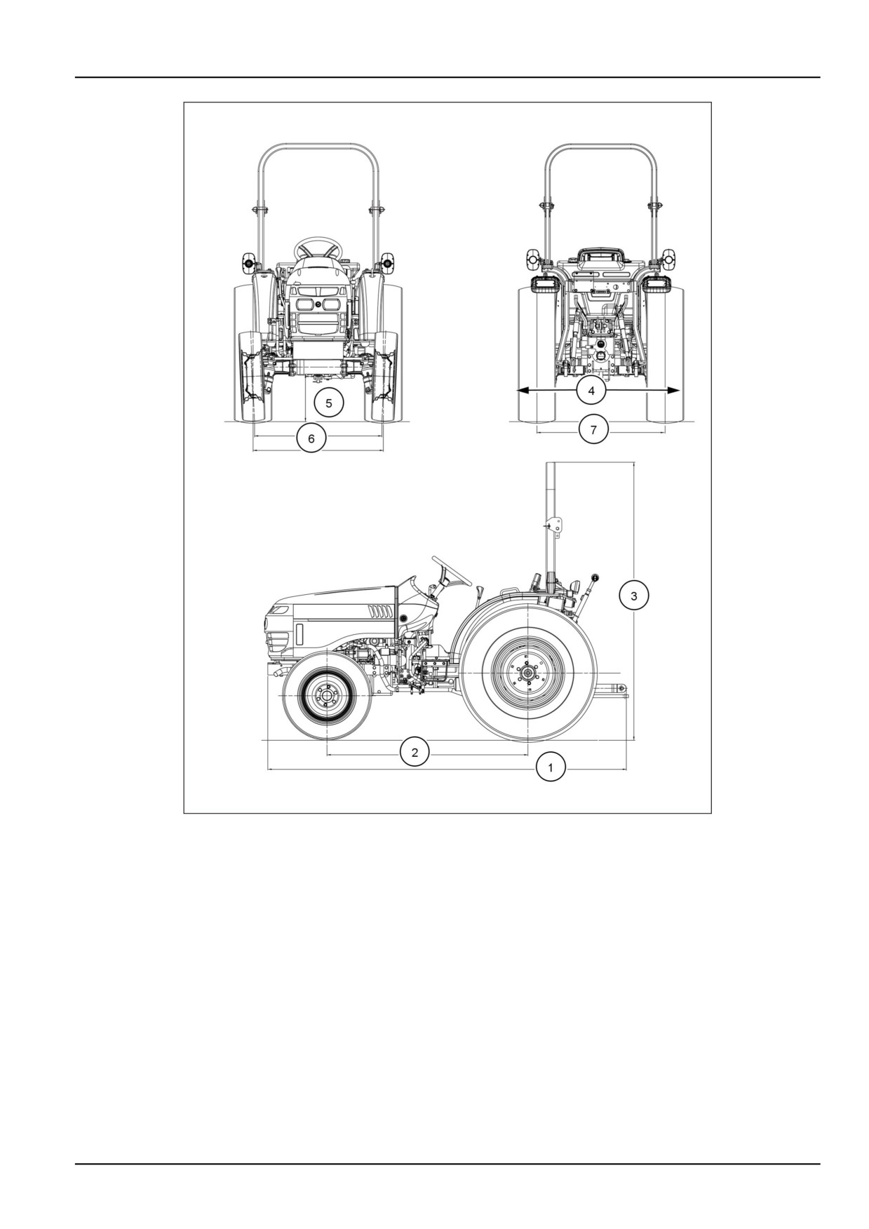
Tractor dimensions
Workmaster™
25
(1) - LENGTH:
FWD:
2988 mm
(117.7 in)
(2) - WHEEL BASE:
FWD
1674 mm
(66.0 in)
(3) - TOP of ROPS - Folding:
Ag. Tires:
11.2-24
Up Position
2241 mm
(88.2 in)
Down Position
1753 mm
(69.0 in)
Turf Tires:
41 x 14.00-20
Up Position
2241 mm
(88.2 in)
Down Position
1722 mm
(67.8 in)
Ind. Tires:
43 x 16-20
Up Position
2241 mm
(88.2 in)
Down Position
1732 mm
(68.2 in)
(4) - WIDTH:Rear Axle
Outside to Outside of Tire
Ag. Tires:
11.2-24
Dished In
1383 mm
(54.45 in)
Dished Out
1639 mm
(64.53 in)
Turf Tires:
41 x 14.00-20
Dished In (Only)
1562 mm
(61.50 in)
Ind. Tires:
43 x 16-20
Dished In (Only)
1639 mm
(66.50 in)
(5) - MINIMUM GROUND CLEARANCE (under drawbar):
Ag. Tires:
11.2-24
261.0 mm
(10.3 in)
Turf Tires:
242 mm
41 x 14.00-20
(9.5 in)
Ind. Tires:
252 mm
43 x 16-20
(10.0 in)
9-7
9 - SPECIFICATIONS
Workmaster™ 25
WHEEL TREAD SETTINGS:
(6)-FRONT:
Ag. Tires:
7-14
1068 mm
(42.0 in)
Turf Tires:
25 x 8.50-14 (Dished In Only)
1159 mm
(45.6 in)
Ind. Tires:
25 x 8.50-14 (Dished In Only)
1159 mm
(45.6 in)
(7)-REAR:
Ag. Tires:
11.2-24
1041 - 1374 mm
(41.0 - 54.1 in)
Turf Tires:
41 x 14.00-20
1208 mm
(47.5 in)
Ind. Tires:
43 x 16-20 (Dished In Only)
1283 mm
(50.5 in)
WEIGHT:
Hydrostatic transmission model
1120 kg
(2469 lb)
Mechanical transmission model
1104 kg
(2434 lb)
9-8
9 - SPECIFICATIONS
NHIL12CT00862HA
1
9-9
9 - SPECIFICATIONS
9-10
10 - ACCESSORIES
10 - ACCESSORIES###_10_###
Optional equipment
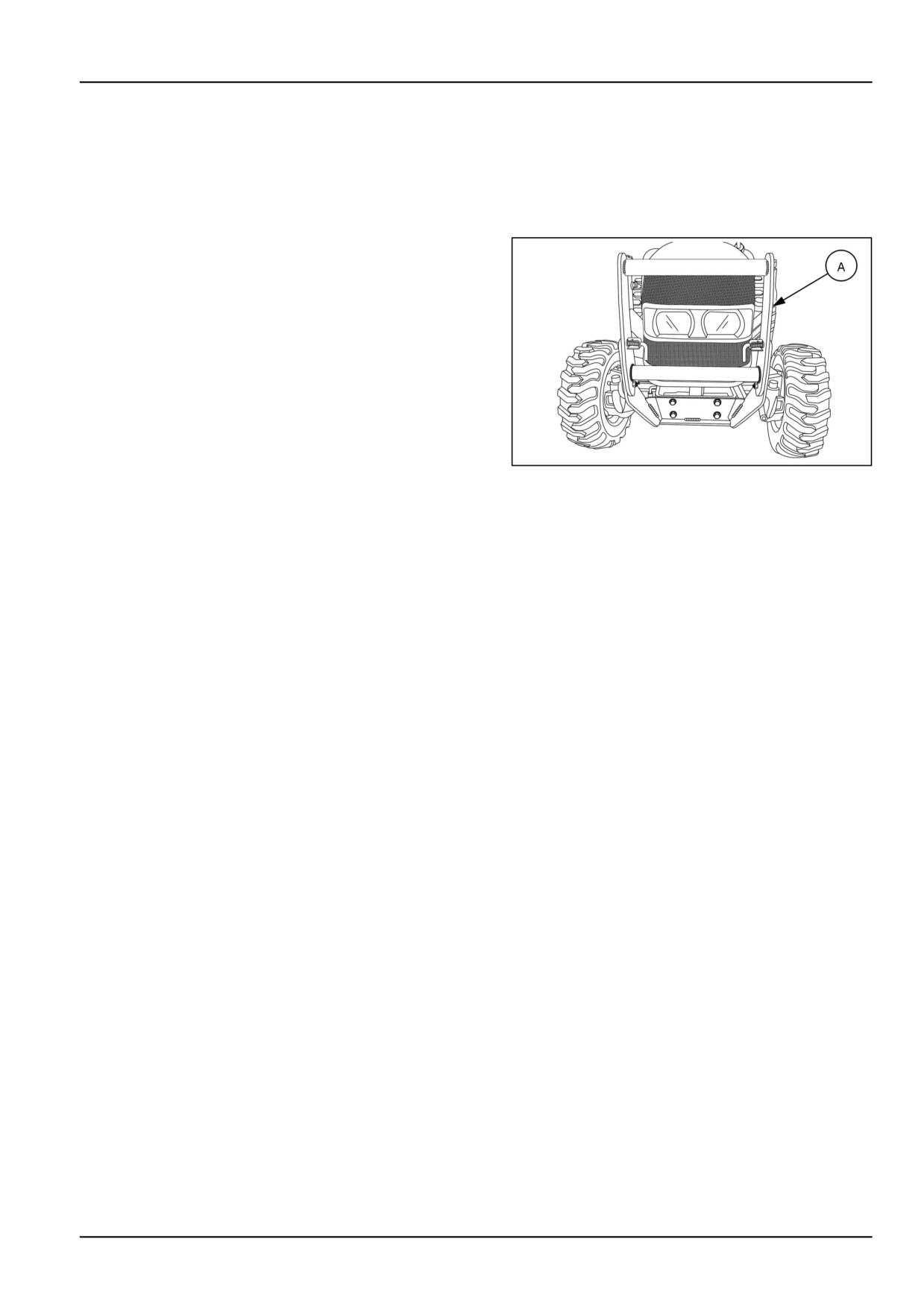
Grille guard
The optional pivoting grille guard (A) provides protection
to the front-end of the tractor. The grille guard is compat-
ible with the front end loader. The grille guard cannot be
used with the front weight carrier.
NHIL17CT01459AA
1
10-1
11 - FORMS AND DECLARATIONS
11 - FORMS AND DECLARATIONS###_11_###
Pre-delivery report - Dealer's copy
Dealer name:
Dealer address:
Model:
Product Identification Number (PIN):
A thorough pre-delivery inspection is time well spent and can prevent unnecessary after-sale service calls.
After you complete the machine assembly, use the following checklist and operator’s manual to thoroughly inspect
the unit. Follow all precautionary safety messages when servicing.
Make adjustments or corrections as required, then check the item off the list.
1. SAFETY SIGN, SHIELDS, and OPERATOR’S PLATFORM
Check all the items below to insure they care installed correctly and operating properly.
Seat Belts Installed
PTO shield installed
Slow Moving Vehicle (SMV) emblem installed
Safety decals installed
Operator presence system/safety interlock system for cranking circuit operation
Park brake operation
Hazard lights/tail lights operation
All lights operation
Operator's Manual (present)
2. FLUID LEVELS and LUBRICATION
Check and top off as necessary.
Engine oil level
Radiator coolant level
Front axle oil level
Transmission & rear axle oil level
Lubricate/grease the entire machine
Fuel level
Wipe off excess grease or oil.
3. WHEELS AND TIRES
Check and inflate tire air pressure to correct pressure. See 9-2.
11-1
11 - FORMS AND DECLARATIONS
Torque the wheel lug bolts to specification. See 7-19.
Front wheels toe-in, See 7-53 for correct specification, Adjust if necessary.
4. OPERATIONAL CHECKS
Perform all operating checks with the tractor at normal operating temperature.
Indicator Lights and gauges for proper operation
Key switch operation
Maximum no-load high and idle speeds, See9-3
PTO engagement and disengagement
Three point hitch operation
Hydraulic lift control drop rate adjustment
Four Wheel Drive (4WD) operation
Operation and adjustment of brakes
Hydrostatic transmission (HST) and 12x12 mechanical shuttle transmission
No fluid or oil leaks
5. OTHER
Check for proper installation of the following items.
Air cleaner element & hose connections
Engine belts tension adjustment
Battery fully charged
Top link
Draw bar
The above pre-delivery service was performed and corrective action taken as required.
Dealer Representative's Signature:
"I have been instructed in the operation, maintenance, and safety features of this machine as detailed in the
operator's manual."
Owner's Signature
Date
Remove this pre-delivery report and retain for future reference.
11-2
11 - FORMS AND DECLARATIONS
Pre-delivery report - Owner's copy
Dealer name:
Dealer address:
Model:
Product Identification Number (PIN):
A thorough pre-delivery inspection is time well spent and can prevent unnecessary after-sale service calls.
After you complete the machine assembly, use the following checklist and operator’s manual to thoroughly inspect
the unit. Follow all precautionary safety messages when servicing.
Make adjustments or corrections as required, then check the item off the list.
1. SAFETY SIGN, SHIELDS, and OPERATOR’S PLATFORM
Check all the items below to insure they care installed correctly and operating properly.
Seat Belts Installed
PTO shield installed
Slow Moving Vehicle (SMV) emblem installed
Safety decals installed
Operator presence system/safety interlock system for cranking circuit operation
Park brake operation
Hazard lights/tail lights operation
All lights operation
Operator's Manual (present)
2. FLUID LEVELS and LUBRICATION
Check and top off as necessary.
Engine oil level
Radiator coolant level
Front axle oil level
Transmission & rear axle oil level
Lubricate/grease the entire machine
Fuel level
Wipe off excess grease or oil.
3. WHEELS AND TIRES
Check and inflate tire air pressure to correct pressure. See 9-2.
Torque the wheel lug bolts to specification. See 7-19.
Front wheels toe-in, See 7-53 for correct specification, Adjust if necessary.
11-3
11 - FORMS AND DECLARATIONS
4. OPERATIONAL CHECKS
Perform all operating checks with the tractor at normal operating temperature.
Indicator Lights and gauges for proper operation
Key switch operation
Maximum no-load high and idle speeds, See9-3
PTO engagement and disengagement
Three point hitch operation
Hydraulic lift control drop rate adjustment
Four Wheel Drive (4WD) operation
Operation and adjustment of brakes
Hydrostatic transmission (HST) and 12x12 mechanical shuttle transmission
No fluid or oil leaks
5. OTHER
Check for proper installation of the following items.
Air cleaner element & hose connections
Engine belts tension adjustment
Battery fully charged
Top link
Draw bar
The above pre-delivery service was performed and corrective action taken as required.
Dealer Representative's Signature:
"I have been instructed in the operation, maintenance, and safety features of this machine as detailed in the
operator's manual."
Owner's Signature
Date
Remove this pre-delivery report and retain for future reference.
11-4