New Holland Workmaster 25, Tier 4B (final) Compact Tractor. OPERATOR’S MANUAL (2020) - page 2
2 - SAFETY INFORMATION
(3)
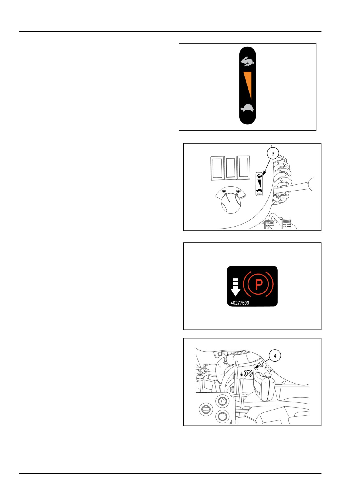
Hand Throttle Lever
• English MT40233965
Location: On the right-hand side of the dash panel.
40233965
6
NHIL12CT00670AA
7
(4)
Park brake
• English MT40277509
Location: On the park brake engagement lever.
40277509B
8
NHIL15CT00353AA
9
2-22
2 - SAFETY INFORMATION
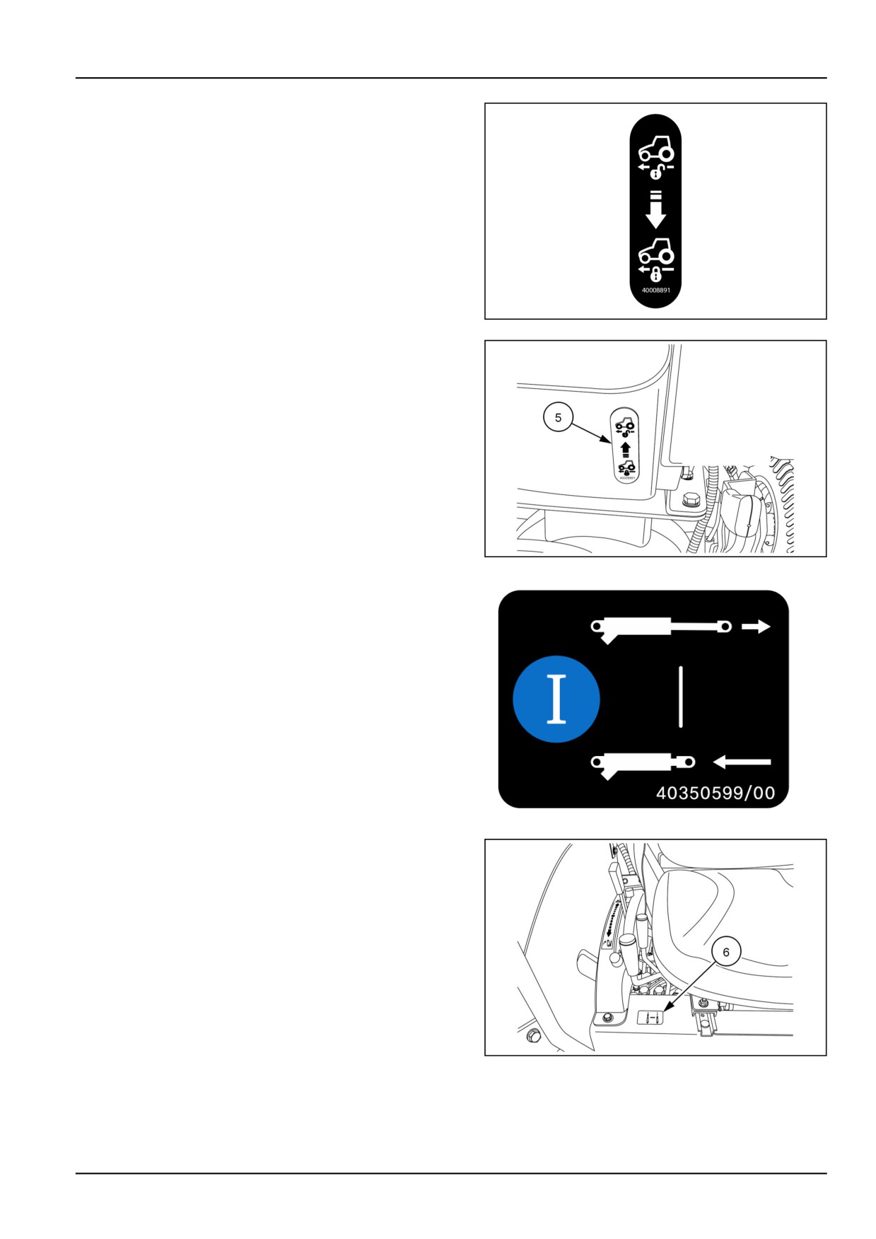
(5)
Hydrostatic Transmission (HST) cruise control
• English MT40008891
Location: Center of the rear hood panel.
40008891C
10
NHIL15CT00354AA
11
(6)
Rear remote valve(s) operation (Optional)
• English MT40350599
Location: On the right-hand side of the platform shield
below the drivers seat.
40350599-00
12
NHIL15CT00374AA
13
2-23
2 - SAFETY INFORMATION
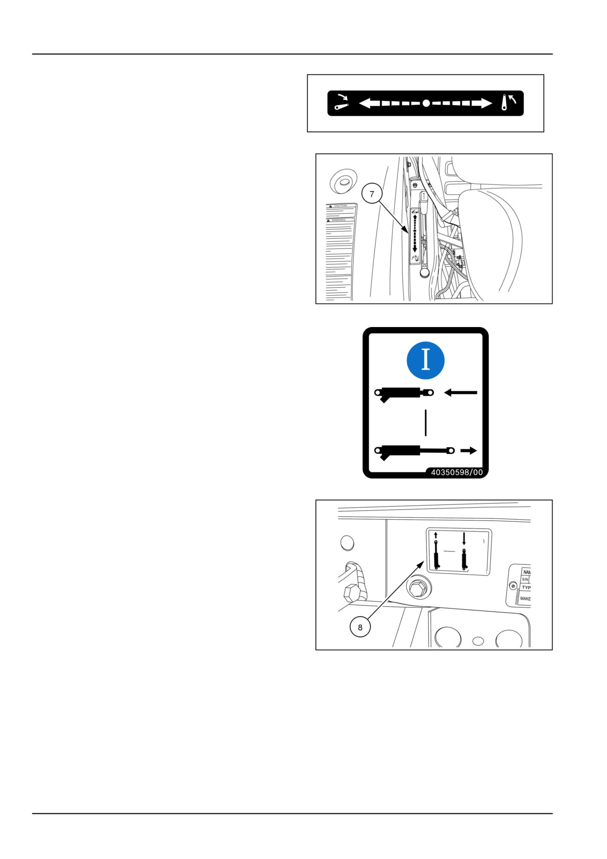
(7)
Position Control Lever
• English MT40254069
Location: On the right-hand side control pod, next to the
drivers seat and right-hand fender.
40254069
14
NHIL12CT00681AA
15
(8)
Rear remote coupler operation.
• English MT40350598
Location : Right rear cross bar support.
40350598-00
16
NHIL13CT01102AA
17
2-24
2 - SAFETY INFORMATION
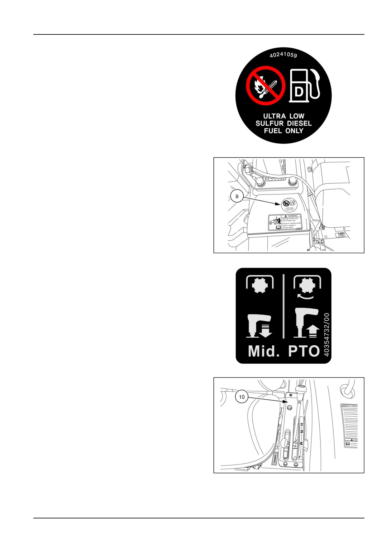
(9)
Fuel
Ultra low sulfur diesel fuel only
• English MT40241059
Location: On top of the left-hand side fender.
40241059-00-1
18
NHIL17CT00212AA
19
(10)
Mid Power Take-Off shift lever (optional)
• English MT40354732
Location: To left side of the drivers seat.
40354732-00
20
NHIL12CT00680AA
21
2-25
2 - SAFETY INFORMATION
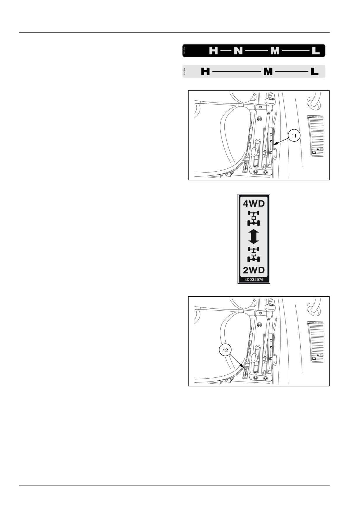
(11)
Transmission range lever
40276753-00
22
• English MT40276753 Hydrostatic Transmission (HST)
English MT40252478 Mechanical Transmission
Location: To left side of the drivers seat.
40252478-00
23
NHIL12CT00680AA
24
(12)
Four wheel drive engagement lever
• English MT40032976
Location: To left side of the drivers seat.
40032976
25
NHIL12CT00680AA
26
2-26
2 - SAFETY INFORMATION
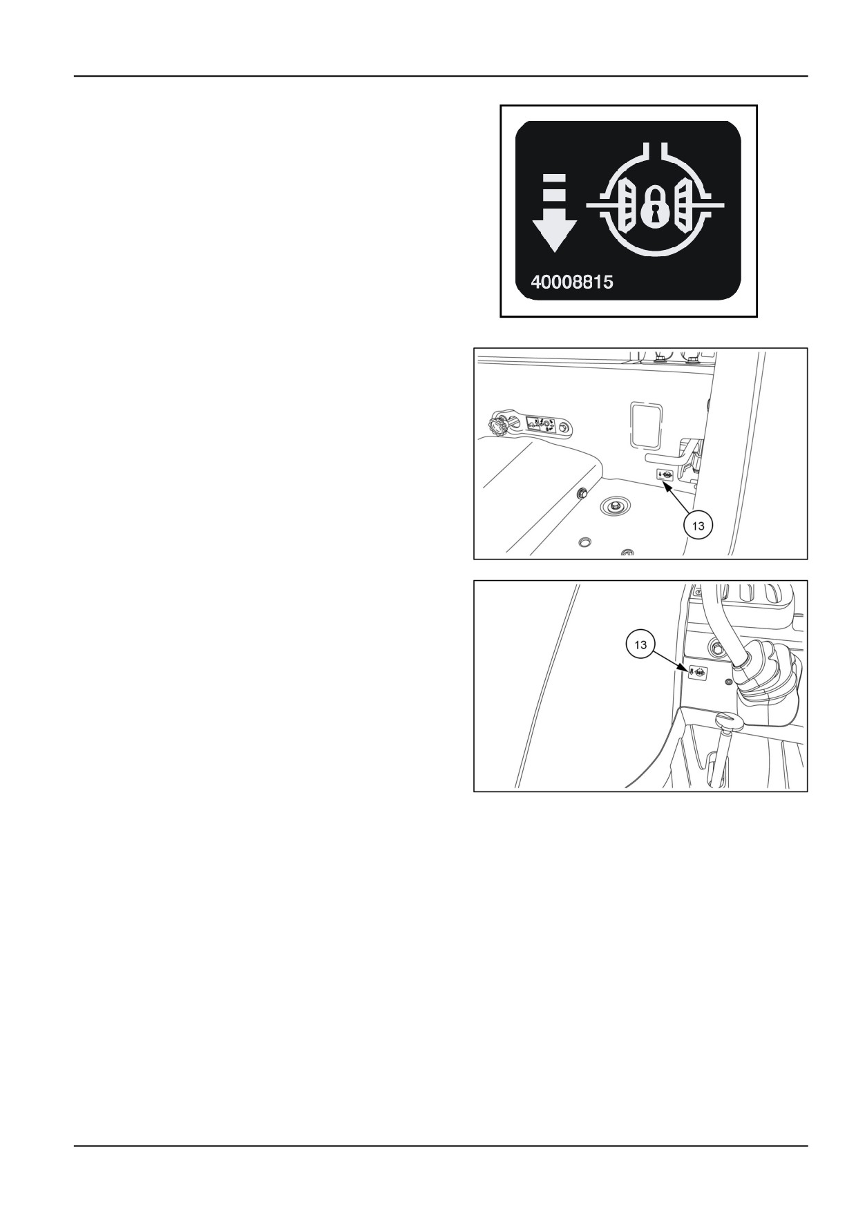
(13)
Differential lock
• English MT40008815
Location: Hydrostatic Transmission (HST) - Left-hand
side of operator’s platform
Mechanical transmission- Right-hand side of operator’s
platform.
40008815
27
NHIL12CT00687AA
28
NHIL13CT01240AA
29
2-27
2 - SAFETY INFORMATION
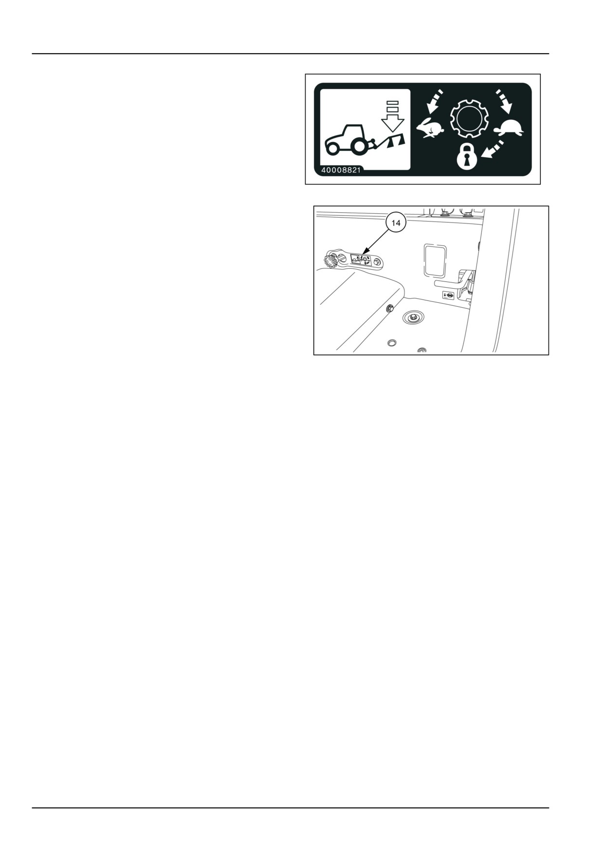
(14)
Drop Rate Control Valve
• English MT40008821
Location: Below the drivers seat.
40008821
30
NHIL12CT00687AA
31
2-28
3 - CONTROLS AND INSTRUMENTS
3 - CONTROLS AND INSTRUMENTS###_3_###
Operator's seat
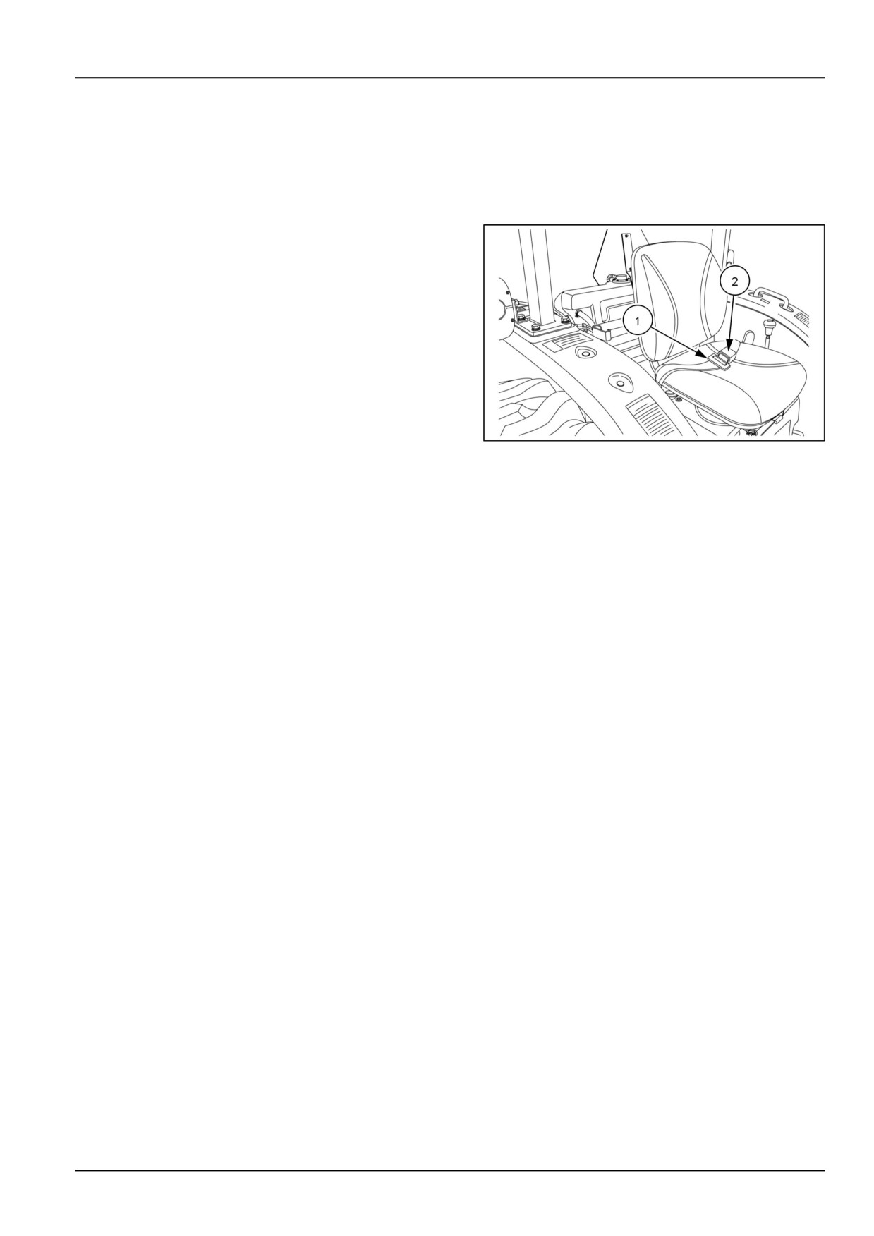
Seat belt
The male end of the seat belt (1) is located on right -hand
side of the seat. To extend length of seat belt, pull out
on male end until correct length is obtained. To latch seat
belt, insert male end into the buckle (2) located on left-
hand side of the seat. Make sure belt is securely buckled
and belt length is adjusted correctly for size of operator.
Use soap and water to clean the seat belt if necessary.
Do not use carbon tetrachloride, naphtha, etc., as these
substances will weaken the webbing. Additionally, do not
bleach or dye the webbing, as these products will also
weaken the webbing.
Replace the seat belt if it becomes damaged or worn.
NHIL12CT00690AA
1
3-1
3 - CONTROLS AND INSTRUMENTS
Seat controls
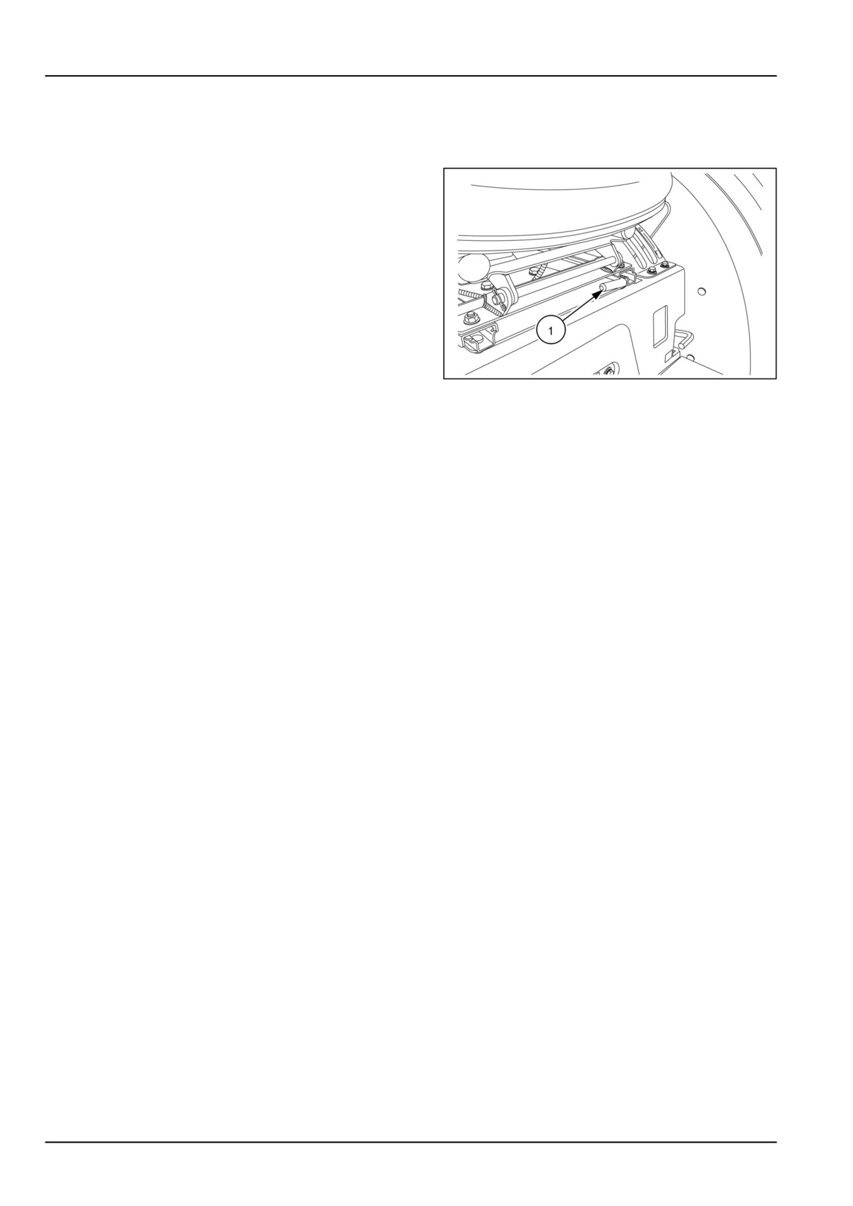
Adjusting the tractor seat
Your tractor is equipped with an adjustable seat.
To move the seat forward or backwards, raise the adjust-
ment lever (1). and move the seat rearward or forward in
the seat track. After the seat is adjusted, release the ad-
justment lever.
The seat can be tilted forward for storage position.
NHIL12CT00682AA
1
Seat cleaning
For cleaning of vinyl, plastic, and rubber parts, use only
a mild car washing soap and water, as described below:
1. First, remove any loose dirt by rinsing with clean water.
Mix a warm, mild liquid CAR WASHING soap solution
(1 part soap and 99 parts water).
2. Use a sponge or soft cloth; apply the soap solution to
the part.
3. Allow the solution to soak for a few minutes to loosen
the dirt.
4. Finally, rinse the part with clean water to remove the
dirt, and any solution residue.
NOTE: If not all of the dirt comes off, repeat the pro-
cedure.
3-2
3 - CONTROLS AND INSTRUMENTS
Roll-Over Protective Structure (ROPS)
WARNING
Misuse hazard!
Your machine is equipped with an operator protective structure. DO NOT weld, drill holes, attempt
to straighten, or repair the protective structure. Modification in any way can reduce the structural
integrity of the structure.
Failure to comply could result in death or serious injury.
W0001B
WARNING
Roll-over hazard!
A folded Roll-Over Protective Structure (ROPS) does not provide roll-over protection. Do not operate
the machine with the ROPS folded as a standard operating mode. Raise the ROPS immediately after
low clearance use or transport.
Failure to comply could result in death or serious injury.
W0938A
WARNING
Crushing hazard!
Always wear the seat belt when operating the machine with the Roll Over Protective Structure (ROPS)
in the upright position. If the ROPS is in the folded position, the seat belt should not be used. Raise
the ROPS and wear the seat belt as soon as conditions allow.
Failure to comply could result in death or serious injury.
W0462A
WARNING
Roll-over hazard!
Always pull from the drawbar. DO NOT attach chains or ropes to the Roll Over Protective Structure
(ROPS) for pulling purposes, as the machine could tip over. When driving through door openings or
under low overhead objects, make sure there is sufficient clearance for the ROPS.
Failure to comply could result in death or serious injury.
W0463A
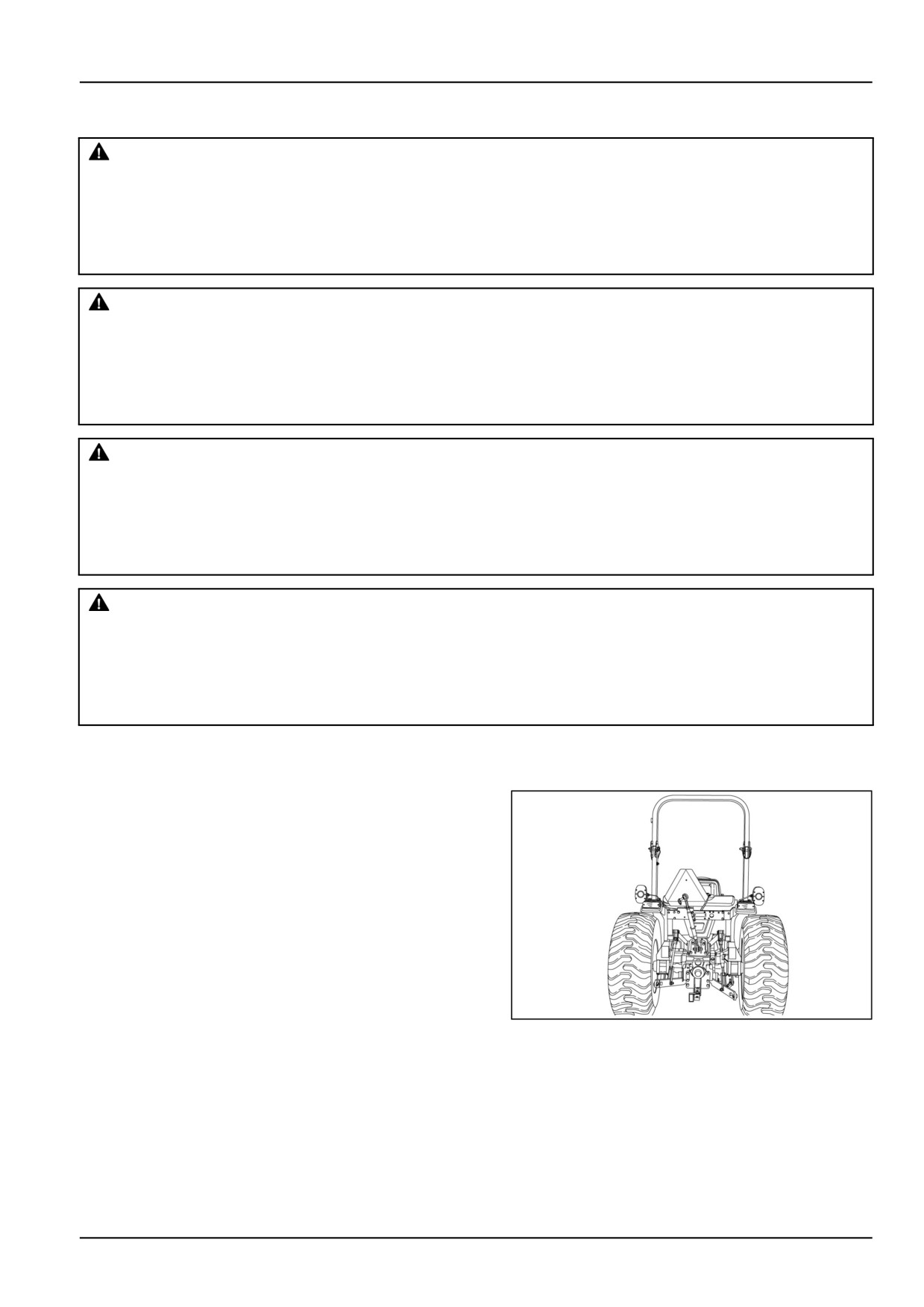
A Roll-Over Protective Structure (ROPS) and seat belts
are standard equipment on this tractor at the time of fac-
tory assembly. If the ROPS was removed by the original
purchaser or has been removed, it is recommended that
you equip your tractor with a ROPS and seat belts.
ROPS are effective in reducing injuries in the event of
tractor overturn. Overturning a tractor without a ROPS
installed can result in serious injury or death. The Rollover
Protective Structure and seat belts are available from your
NEW HOLLAND Dealer.
Additionally, the safety offered by the ROPS and seat belt
is minimized if your seat belt is not buckled. Always use
NHIL12CT00671AA
1
your seat belt when the ROPS is in the "UP" position, it
can save your life.
3-3
3 - CONTROLS AND INSTRUMENTS
Foldable ROPS
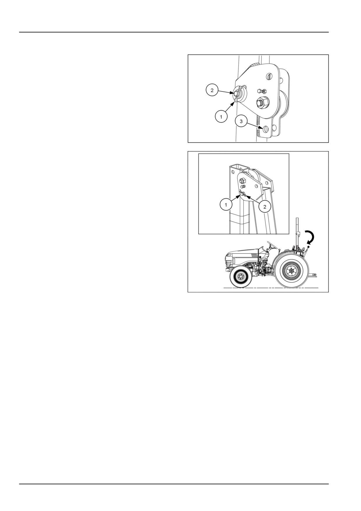
A foldable Rollover Protective Structure (ROPS), is fac-
tory installed. Operate with this ROPS in the "UP" position
whenever possible. Use the ROPS in the "folded" position
only when absolutely necessary.
ROPS folding procedure
To fold the ROPS into the "DOWN" position, remove re-
taining clip (1) from the pin (2) and remove pin from the
latching bracket, on both sides of the ROPS. Rotate the
top part of the ROPS downward until the brackets contact
the ROPS uprights. Reinstall pin (2) into lower retaining
hole (3).
93099328
2
Secure the pin (1) with the retaining clip (2).
NHAC13CT00064GA
3
3-4
3 - CONTROLS AND INSTRUMENTS
Forward controls
Instrument cluster panel
NHIL17CT01803FA
1
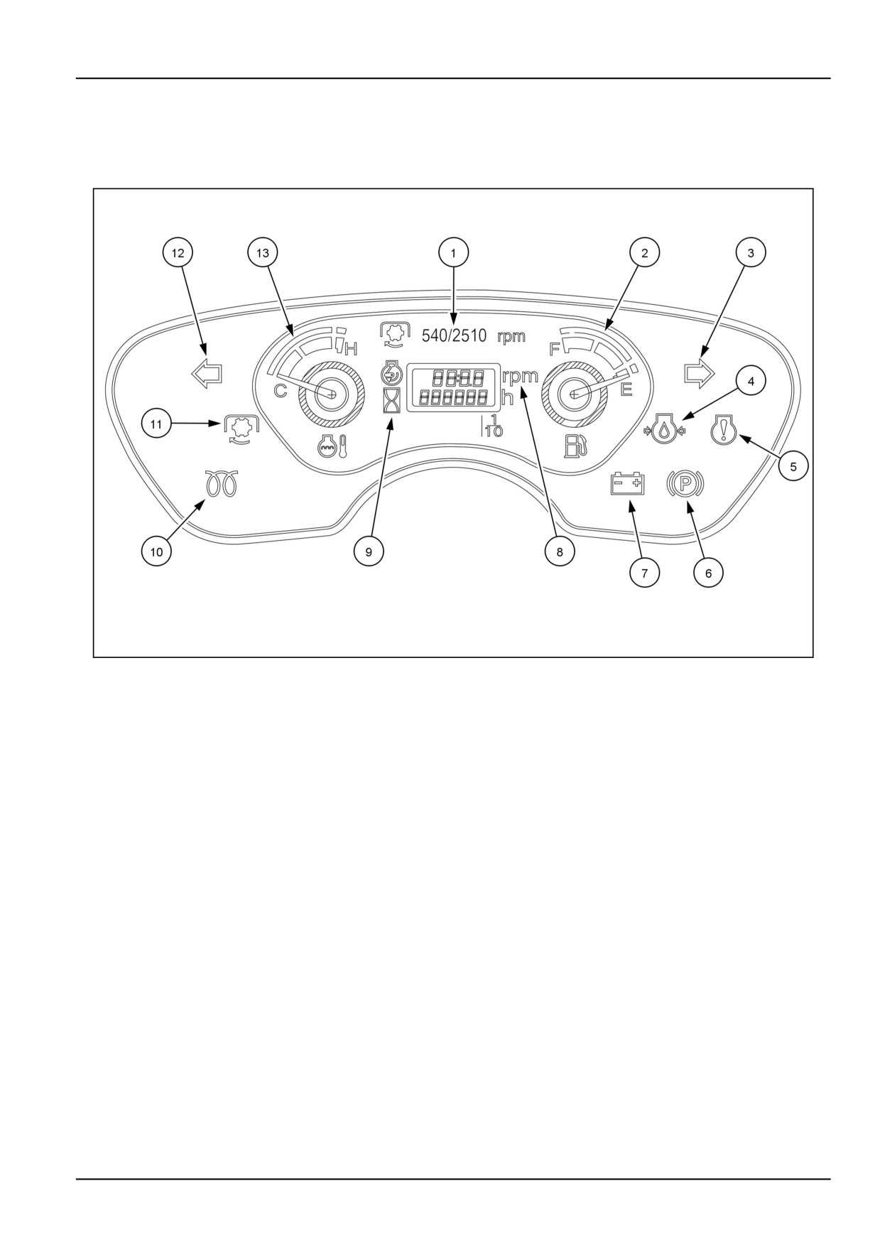
The following icons and indicators will display on the instrument cluster during operation of the tractor. Become familiar
with each item and when you might see them based on the operating conditions of the tractor.
(1) This text informs to obtain a rear Power Take-Off (PTO) speed of 540 RPM the engine speed must be 2510 RPM.
(2) Fuel Gauge - Indicates the amount of diesel fuel remaining in the tank. The gauge will activate when the key
switch is in the "ON" position. It will register "empty" with the key switch in the "OFF" position.
(3) Flasher Turn Lights - Operate when the multifunction switch lever is moved upwards for right turns the right arrow
will flash. The flasher warning lights will also cause this to display. The key switch has to be in the "ON" or "START"
positions.
(4) Engine Oil Pressure Warning Light - Illuminates with the key switch in the "ON" position and remains illuminated
for a short period, after you start the engine. The light indicates low engine oil pressure only and goes out when
sufficient oil pressure is present at the oil sender. If the bulb illuminates during operation, stop the tractor immediately,
and investigate the cause.
(5) Engine Fault Warning Light - Illuminates when the key switch is in the "ON" position and goes out when the oper-
ator starts the engine. See your NEW HOLLAND dealer if this light illuminates during operation of your tractor, this
indicates a fault with the engine speed control unit.
(6) Park Brake Indicator Light - Illuminates if the park brake is engaged with the key switch rotated to the "ON" position.
(7) Battery Charge Warning Light - Illuminates when the key switch is in the "ON" position and goes out when the
operator starts the engine. An illuminated bulb during this operation indicates the charging system is not operating
normally.
(8) Tachometer - Registers engine speed in Revolutions Per Minute (RPM).
3-5
3 - CONTROLS AND INSTRUMENTS
(9) Hour Meter - Records the hours and portions of hours that your tractor has accumulated regardless of engine
RPM. Use the hour meter as a guide to determine hourly service and maintenance intervals.
(10) Cold Starting Indicator Light - Illuminates when the key switch is turned to the "PRE-HEAT" or “START” position.
When the indicator light is illuminated, the glow plugs are heating the engine combustion chambers.
(11) PTO Indicator Light - When either the rear or mid PTO is engaged, the indicator will be illuminated with the key
in the "START" or "ON" positions.
(12) Flasher Turn Lights - Operate when the multifunction switch lever is moved downwards for left turns the left arrow
will flash. The flasher warning lights will also cause this to display. The key switch has to be in the "ON" or "START"
positions.
(13) Temperature Gauge - Indicates coolant temperature. It activates when you turn the key switch to the "ON" posi-
tion. The gauge will register cold with the key switch in the "OFF" position. If the needle registers in the white range
of the gauge, this indicates a normal operating temperature. If the needle moves to the red portion of the gauge, this
indicates an overheated condition. Stop the tractor engine immediately and investigate the cause.
3-6
3 - CONTROLS AND INSTRUMENTS
Cruise control
WARNING
Loss of control hazard!
To maintain optimum control of the machine, do not use the cruise control at high speeds or when
roading.
Failure to comply could result in death or serious injury.
W0978A
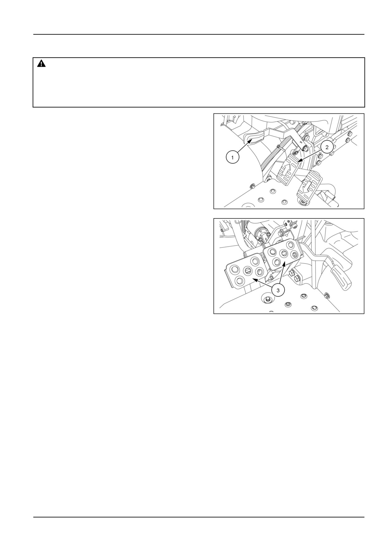
The HST cruise control lever (1) is located on the right
-hand side of the operator’s platform. It is used to maintain
a constant forward speed.
NOTE: The cruise control is only found on HST model
tractors.
When the desired travel speed is reached, push down-
wards on the cruise control engagement lever while de-
pressing the HST forward pedal (2). The engagement
lever will mechanically retain the forward pedal in the de-
sired speed location. To disengage the cruise control,
depress the HST forward pedal slightly or depress both
brake pedals (3).
NHIL12CT00693AA
1
NHIL12CT00691AA
2
3-7
3 - CONTROLS AND INSTRUMENTS
Transmission shuttle shift lever
WARNING
Equipment rolling hazard!
Firmly apply the handbrake and place the shuttle lever in the park brake position. Stop the engine
before leaving the machine. The transmission will not prevent the machine from rolling when the
engine is shut off.
Failure to comply could result in death or serious injury.
W0378A
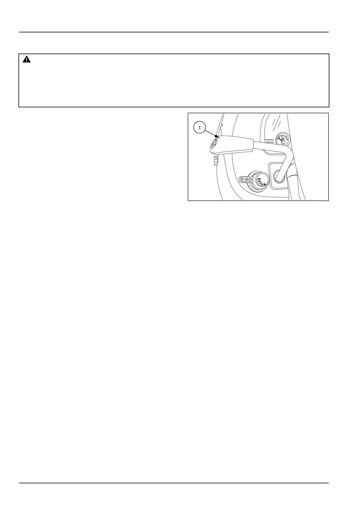
The transmission shuttle shift lever (1) is located on the
left-hand side of the dash panel. The shuttle shift lever is
used to engage the transmission into forward or reverse
mode while depressing the clutch pedal. Move the lever
forward for forward travel and rearward for reverse travel.
NOTICE: Do not attempt to operate the shuttle lever while
the tractor is moving, it may cause damage to the syn-
chromesh gear. The clutch pedal must be depressed and
tractor motion stopped to operate the shuttle lever.
NOTE: The shuttle shift lever is only found on mechanical
transmission tractors.
NOTE: The shuttle lever must be in the neutral (middle)
93099335
1
position to activate the safety start system, which allows
the engine to start.
3-8
3 - CONTROLS AND INSTRUMENTS
Clutch pedal
WARNING
Loss of control hazard!
Machines with four-wheel drive engaged or disengaged should not exceed 50 km/h (31 mph) where
permitted. Over speeding by towing or coasting downhill with clutch depressed or transmission in
neutral may cause loss of control, personal injury to the operator or bystanders, or mechanical failure.
Failure to comply could result in death or serious injury.
W0454A
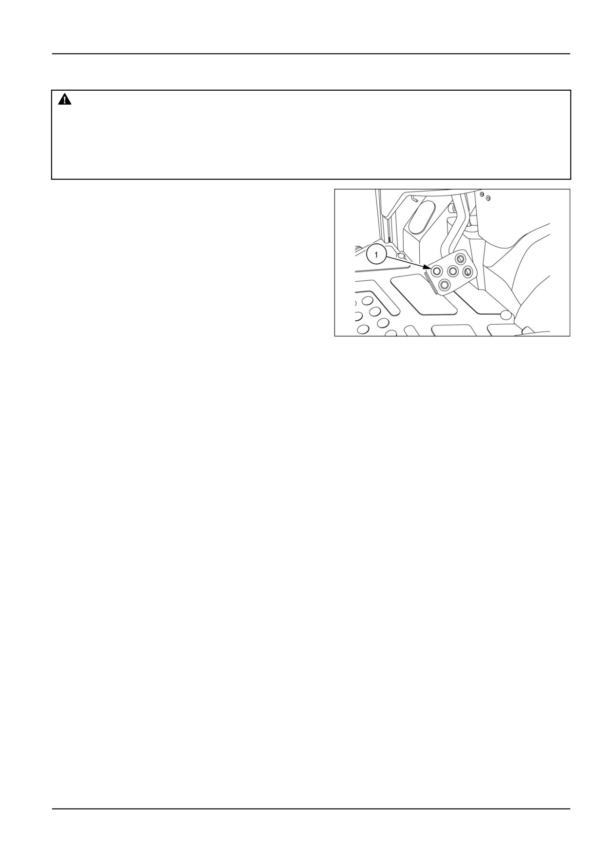
The clutch pedal (1) controls the single-stage clutch and
is located on the left-hand side of the operators platform.
The clutch pedal is only found on mechanical transmission
model tractors.
93099348
1
3-9
3 - CONTROLS AND INSTRUMENTS
Brake pedals
WARNING
Loss of control hazard!
Uneven brake force exists on left-hand and right-hand brakes. To ensure uniform brake application
and maximum stopping ability, always lock the service brake pedals together before road travel.
Failure to comply could result in death or serious injury.
W1188A
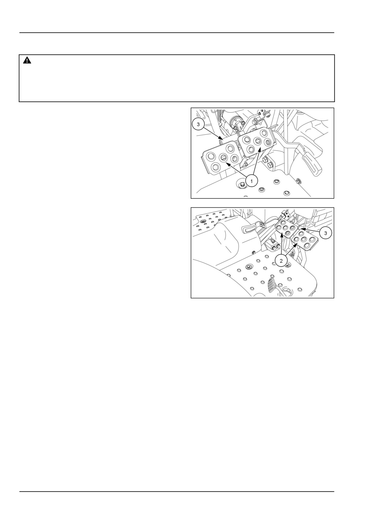
The right brake pedal controls the braking action of the
right rear wheel. The left brake pedal controls the braking
action of the left rear wheel.
The function of the brake pedals are identical for the Hy-
drostatic Transmission (HST) and mechanical transmis-
sion model tractors except for the location of the ped-
als. The brake pedals (1) on a HST model tractor are lo-
cated on the left-hand side of the operators platform and
the brake pedals (2) on a mechanical transmission model
tractor are located on the right-hand side of the operators
platform.
Depress both pedals simultaneously to stop the tractor.
NHIL12CT00691AA
1
To assist in making sharp turns at slow speed, depress
the right or left brake pedal as required.
The brake pedal connecting pin (3) is used to secure the
brake pedals together. Lock the pedals together when-
ever the tractor is operated at high speeds or when the
tractor is used on the highway.
NHIL13CT00044AA
2
3-10

3 - CONTROLS AND INSTRUMENTS
Foot throttle pedal
The foot throttle pedal (1) may be used independent of the
hand throttle lever to control the speed of the tractor.
NOTE: The foot throttle pedal is found only on mechanical
transmission model tractors.
NOTE: It is recommended to use the foot throttle pedal
when driving on the main road or highway.
NOTE: When using the foot throttle pedal, the hand throt-
tle lever should be in the (low idle) rearward position.
NHIL13CT00044AA
1
3-11

3 - CONTROLS AND INSTRUMENTS
Hand throttle lever
The hand throttle lever (1) is located on the right-hand side
of the dash panel.
Push the lever forward to increase the engine speed and
rearward to decrease the engine speed.
NOTE: The hand throttle lever should only be used during
field operation.
NHIL12CT00692AA
1
3-12

3 - CONTROLS AND INSTRUMENTS
Horn switch (optional)
The horn switch (1) is located on the right-hand side of the
dash panel.
To activate the horn, push the horn switch down. The horn
switch can be activated with the key switch in the "ON"
position.
NHIL12CT00727AA
1
3-13
3 - CONTROLS AND INSTRUMENTS
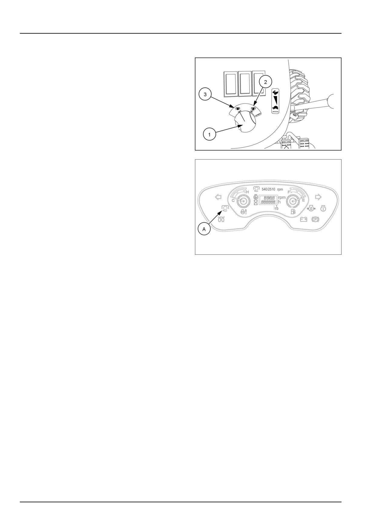
Power Take-Off (PTO) switch
The PTO switch (1) is located on the right-hand side of
the dash panel.
NOTE: Place the PTO switch in the “OFF” position to start
the engine.
To engage the PTO, push down on the PTO switch and
turn the switch to the "ON" position (2).
NOTE: Only engage the PTO when the engine is at low
idle speed. This will reduce the shock load on the drive-
line of the attachment.
When the PTO is engaged the PTO indicator light (A) will
be illuminated on the instrument panel.
NHIL12CT00670AA
1
To disengage the PTO, push down on the PTO switch and
the switch will automatically return to the "OFF" position
(3).
For PTO operating instructions see page 3-8.
NHIL17CT01803FA
2
3-14

3 - CONTROLS AND INSTRUMENTS
Key switch
The key switch (A) is located on the right-hand side of
the rear hood panel. Turning the key to the "ON" position
(2) activates the warning lights, instruments, and preheat
system. The engine starts when the key is turned to the
"START" position (3). An internal spring returns the key
to the "ON" position when released.
Turning the key to the "STOP" position (1) will shut the
engine off.
NHIL12CT00692AA
1
3-15
3 - CONTROLS AND INSTRUMENTS
Differential lock pedal
WARNING
Steering is difficult with the differential lock engaged. An accident could result.
During field operation, use the differential lock for traction improvement but release for turning at row
end. Do not drive at high speeds or on roads with the differential lock engaged.
Failure to comply could result in death or serious injury.
W0292A
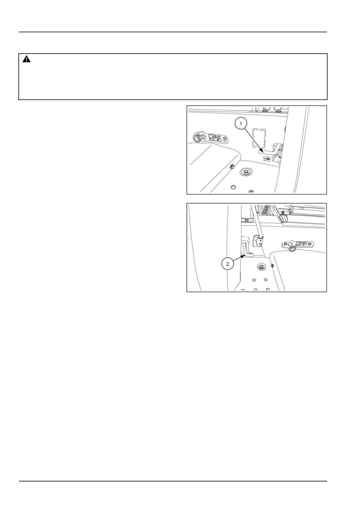
The differential lock pedal is located on the left-hand foot
platform (1) on hydrostatic transmission models and on
the right-hand foot platform (2) on mechanical transmis-
sion models. The differential lock is used to obtain addi-
tional traction in wet or loose soil.
When the differential lock pedal is depressed, power is
split evenly between the two rear wheels. Whenever one
wheel begins to slip in wet or loose soil, use the lock to
obtain additional traction from the opposite wheel.
To operate the differential lock, depress and hold the
pedal down until the lock is positively engaged. It is best
to engage the lock while the wheels are turning slowly to
NHIL12CT00687AA
1
minimize shock loads to the drive-line. If a wheel spins at
high speed, such as on ice, reduce engine speed to idle
before engaging the lock or damage may result. Release
the pedal to disengage the differential lock.
NOTE: In some instances, the lock may remain engaged
after the pedal is released. This can occur if one rear
wheel is turning at a faster speed than the other. The lock
can be disengaged in one of two ways if this occurs:
• Decrease the drawbar pull by raising or disengaging the
implement so that neither wheel tends to slip.
• Depress the clutch pedal and rapidly apply and release
a light braking load to the wheel with less traction.
NHIL13CT00039AA
2
3-16

3 - CONTROLS AND INSTRUMENTS
Hydrostatic Transmission (HST) foot pedals
The ground speed of tractors equipped with a Hydrostatic
Transmission, (HST) is continuously variable, from zero
to full rated speed in each range. Speed is controlled by
the HST forward (1) and reverse (2) pedals located on the
right-hand foot platform.
For forward travel, depress the forward pedal (1) until the
desired ground speed is reached. For reverse travel, de-
press the rear pedal (2). The transmission returns to neu-
tral and the tractor stops when the pedal is released.
NHIL12CT00693AA
1
3-17
3 - CONTROLS AND INSTRUMENTS
Multifunctional light switch
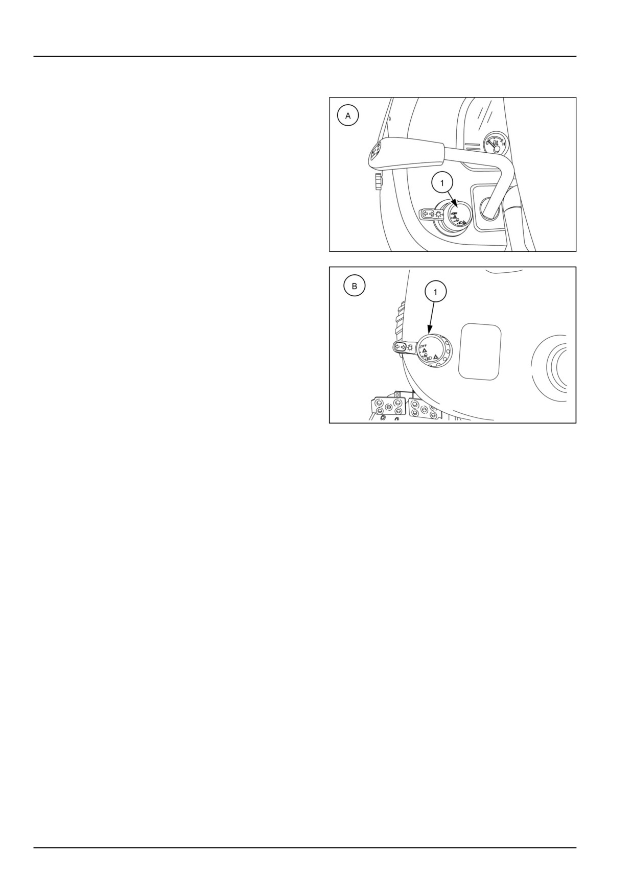
The multifunction light switch (1) is located on the left-
hand side of the dash panel and is used to control the
front road lights/work lights, side/taillights, hazard lights
and turn signals.
93099335
1
NHIL12CT00669AA
2
(A) Mechanical transmission model
(B) Hydrostatic Transmission (HST) model
3-18
3 - CONTROLS AND INSTRUMENTS
Left-hand side controls
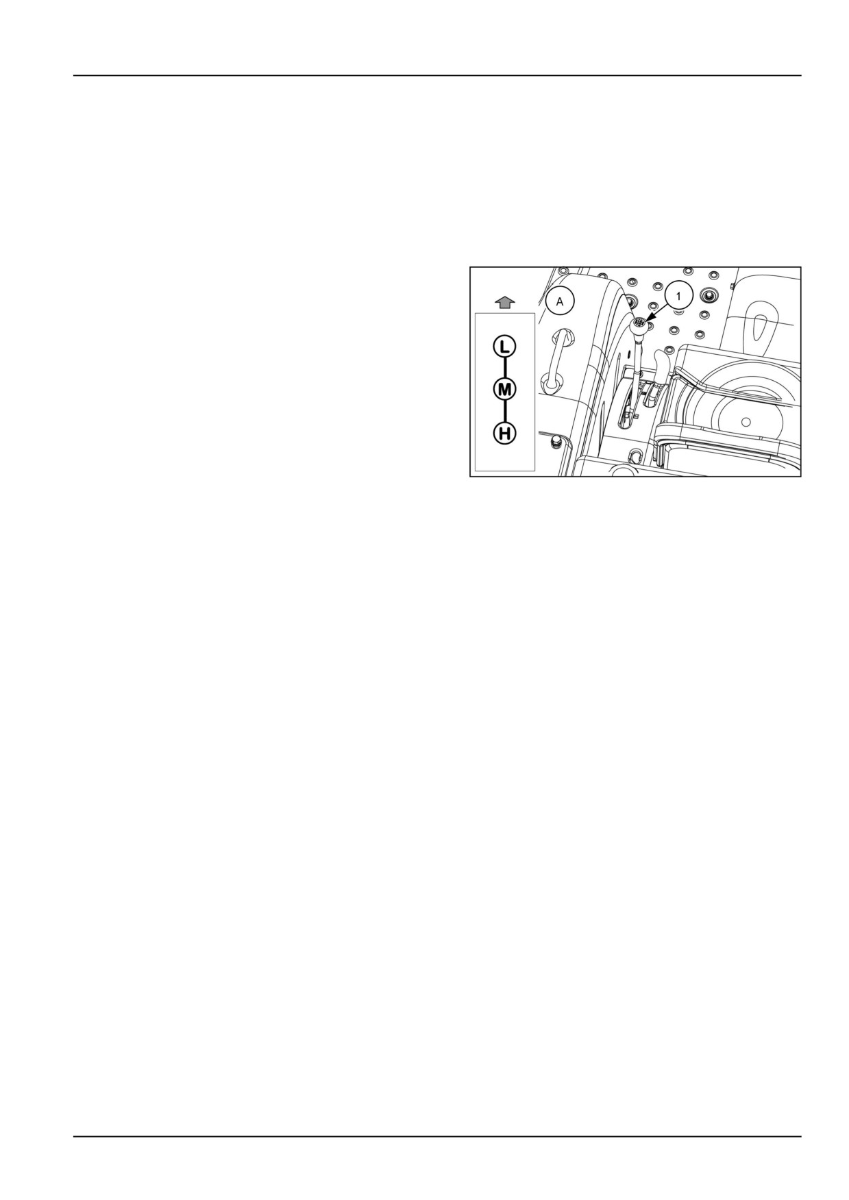
Transmission range lever
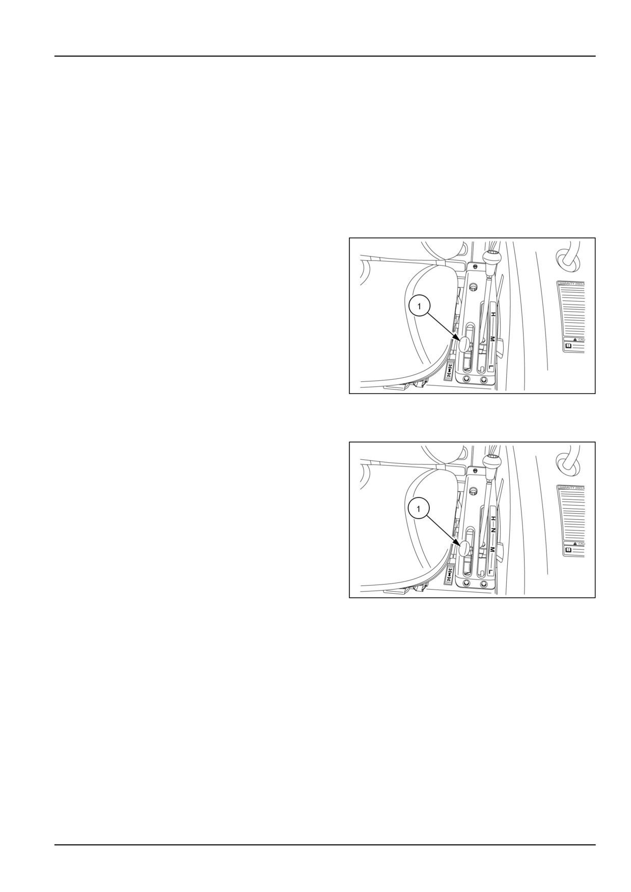
The transmission range selector lever (1) is located on the left-hand control pod. There are three speed ranges, (H)
High, (M) Medium, and (L) Low. The transmission range selector lever on mechanical transmission models (A) do
not have a (N) Neutral position.
NOTICE: Never attempt to engage or disengage the range lever when the tractor is in motion.
NHIL12CT01097AA
1
(A) Mechanical transmission models
3-19
3 - CONTROLS AND INSTRUMENTS
Park brake lever
WARNING
Unexpected machine movement!
Always engage the parking brake before exiting the machine.
Failure to comply could result in death or serious injury.
W1011B
NOTICE: Ensure the park brake is fully disengaged before
driving the tractor.
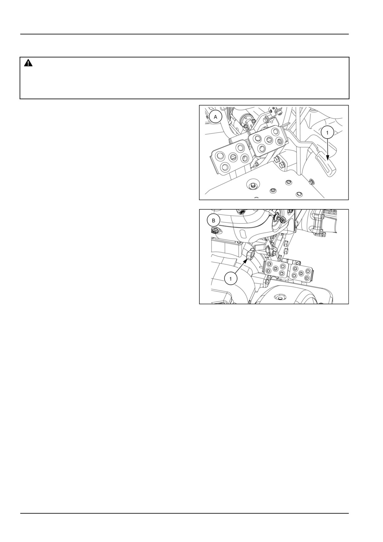
The park brake lever (1) is located on the left-hand side
of the operators platform on HST model tractors (A) and
on the right-hand side on mechanical transmission model
tractors (B). The park brake is used to secure the brake
pedals together to prevent the tractor from moving while
parked.
To engage the park brake, lock the pedals together and
push the park brake lever downward while depressing the
brake pedals.
NHIL12CT00691AA
1
NOTE: Always engage the park brake when getting off
the tractor. If the brakes are not engaged or the operator
leaves the seat without engaging the park brake a alarm
will sound. The alarm will continue to sound for approxi-
mately ten seconds or until the park brake is engaged.
To disengage the park brake, press the brake pedals
down.
NHIL12CT00775AA
2
3-20
3 - CONTROLS AND INSTRUMENTS
Four-Wheel Drive (4WD) lever
The four wheel drive (4WD) is controlled by a lever. The
lever is located on the left-hand control pod.
NOTE: Use four wheel drive when additional traction is re-
quired while operating on loose soil, in wet, slippery con-
ditions, or on slopes. For normal operation on firm soil,
level hard surfaces, or when operating the unit at high
speeds, disengage the four wheel drive to maximize tire
and drive-line life and to obtain better fuel economy.
Mechanical transmission model
To engage the four wheel drive on mechanical transmis-
sion model tractors, stop the tractor completely, depress
the clutch pedal and move the lever (1) completely for-
ward. To disengage the four wheel drive, stop the tractor
completely, depress the clutch pedal and pull the lever (1)
rearward.
NHIL12CT00885AA
1
Hydrostatic Transmission (HST) model
To engage the four wheel drive on HST model tractors,
stop the tractor completely and move the lever (1) com-
pletely forward. To disengage the four wheel drive, stop
the tractor completely and pull the lever (1) rearward.
NHIL12CT00680AA
2
3-21

3 - CONTROLS AND INSTRUMENTS
Mid Power Take-Off (PTO) lever
The mid PTO lever (1) is located on the left-hand control
pod.
NOTE: The mid PTO is standard equipment on Hydro-
static Transmission (HST) and optional on mechanical
transmission model tractors.
To engage the mid PTO, pull up on the mid PTO lever,
push down on the PTO switch and turn the switch to the
"ON" position.
NOTE: When the mid PTO is engaged the rear PTO will
also be engaged. The mid PTO cannot be engaged sep-
arately.
NHIL12CT00772AA
1
To disengage the mid PTO, push down on the PTO switch
and push the mid PTO lever down to the "OFF" position.
NOTE: To start the engine the mid PTO lever must be in
the down (disengaged) position and the PTO switch in the
"OFF" position.
3-22
3 - CONTROLS AND INSTRUMENTS
Right-hand side controls
Hydraulic Power Lift (HPL) lever
DANGER
Crushing hazard!
Make sure area is clear of all persons before lowering equipment.
Failure to comply will result in death or serious injury.
D0016A
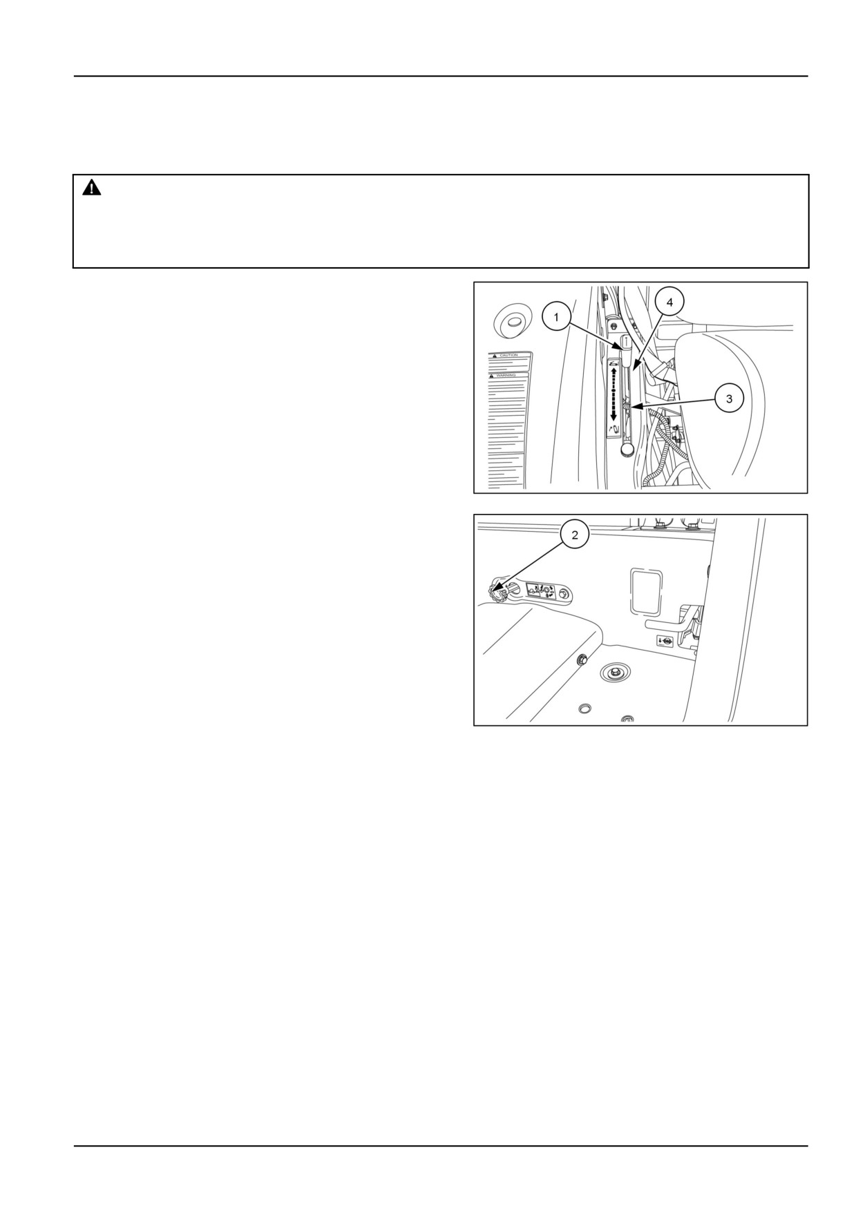
The HPL lever (1) is located on the right-hand control pod.
This lever controls the position of the two lift arms.
To lower the lift arms, first make sure the drop rate con-
trol valve (2) is open, then move the HPL lever forward. To
raise the lift arms, move the lever rearward. An adjustable
lower stop (3) is located in this quadrant for returning the
lever to a preset lowering position of the hitch. An ad-
justable upper HPL control lever height stop (4) prevents
the control lever from exceeding the lift limit and causing
the tractor hydraulic system to go over the relief valve set-
ting.
The hydraulic lift system provides accurate, smooth, and
instant hydraulic power for raising a variety of compatible
equipment whenever the engine is running. The system's
NHIL12CT00681AA
1
position control feature maintains the selected height or
depth of three-point linkage equipment in relation to the
tractor. When the hydraulic lift control lever is moved to a
higher or lower setting in the quadrant, the system repo-
sitions the equipment to a higher or lower position and
maintains the selected position.
NHIL12CT00687AA
2
Position control
Position control provides easy, accurate control of the three-point linkage equipment which operated above the ground,
such as sprayers, rakes, mowers etc. It also provides uniform depth when using a blade or similar equipment on
ground level.
When operating in position control, there is a definite relationship between the position of the control lever in the
quadrant and the position of the equipment. The lever must be moved to change the position of the equipment relative
to the tractor. The system will automatically maintain the equipment in the selected position.
3-23
3 - CONTROLS AND INSTRUMENTS
Rear remote control valve(s) - optional
WARNING
Escaping fluid!
Do not connect or disconnect hydraulic quick coupler under pressurized conditions. Make sure all
hydraulic pressure is removed from the system before connecting or disconnecting hydraulic quick
coupler.
Failure to comply could result in death or serious injury.
W0095B
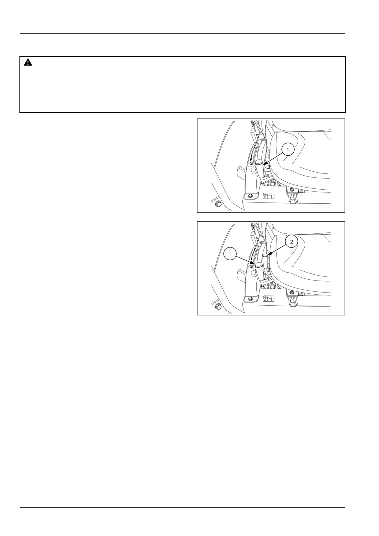
Your tractor can be equipped with one or two optional rear
remote hydraulic valves. The control lever(s) (1) and (2)
is/are located right side of the seat.
NOTE: The rear remote hydraulic valves are optional
equipment.
NOTE: Rear remote hydraulic valve kits are configured
in either single spool or two spool. Once a single spool
valve is installed, you CANNOT stack another single spool
valve. You must purchase the two spool valve kit.
NHIL15CT00390AA
1
NHIL15CT00374AA
2
To operate the one spool valve, pull the selected control lever rearward to extend the cylinder and push the control
lever forward to retract the cylinder. The #1 control lever (blue knob) is a detent type control valve. This valve will
remain in the raise or lower position and will require the operator to manually return the control lever to the neutral
position. This is useful in operating a hydraulic motor or a long stroke hydraulic cylinder. Return the control lever to
neutral to stop the hydraulic motor or to hold the hydraulic cylinder in any position. This valve will not return to neutral
once a hydraulic cylinder reaches the end of stroke. It is important to return the control lever to neutral when not using
the control valve.
To operate the two spool valve, pull the selected control lever rearward to extend the cylinder and push the control
lever forward to retract the cylinder. The #1 control lever (green knob) is a self-centering type control valve. Release
the control lever to stop the cylinder in any position before it reaches full extension. The lever automatically returns
to neutral. The #2 control lever (blue knob) is a detent type control valve. This valve will remain in the raise or lower
position and will require the operator to manually return the control lever to the neutral position. This is useful in
operating a hydraulic motor or a long stroke hydraulic cylinder. Return the control lever to neutral to stop the hydraulic
motor or to hold the hydraulic cylinder in any position. This valve will not return to neutral once a hydraulic cylinder
reaches the end of stroke. It is important to return the control lever to neutral when not using the control valve.
3-24
3 - CONTROLS AND INSTRUMENTS
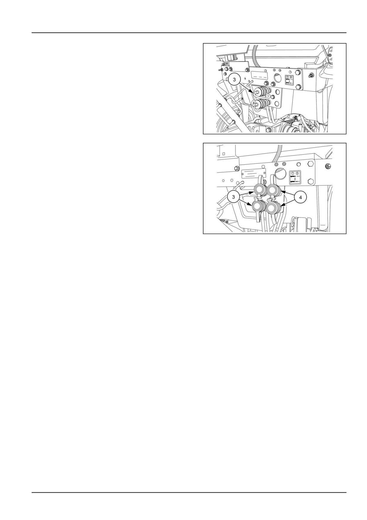
The #1 (blue) set of couplers (3) is located inboard and
the #2 (green) set of couplers (4) is located outboard.
The rear remote valves come standard with 12.7 mm
(0.5 in) female quick couplers .
NHIL15CT00392AA
3
NHIL15CT00373AA
4
3-25
3 - CONTROLS AND INSTRUMENTS
Transmission speed shift lever
Mechanical transmission model
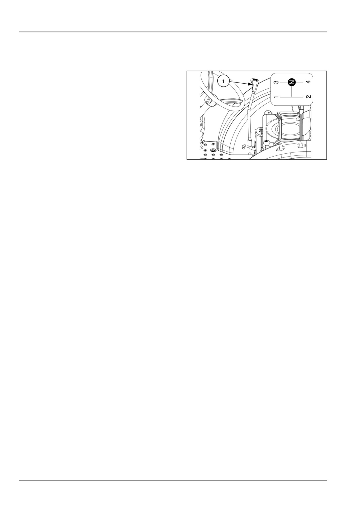
The transmission main gear shift lever (1) is located on
the right-hand side of the operators platform, and is used
to select any one of the four forward or reverse gears.
NOTE: With the combination of the shuttle shift, main
shift, and range selector lever offer the operator a com-
bination of twelve forward and twelve reverse gears.
NHIL12CT00776AA
1
The main gear shift lever must be operated only AFTER the tractor has stopped completely. Shift the main gear shift
lever by designated “H” pattern. If the main gear shift lever is operated when the tractor is in motion, damage to the
transmission gears could occur.
NOTE: The shift pattern is shown as sitting in the operators seat.
3-26
3 - CONTROLS AND INSTRUMENTS
Exterior controls
Hood release lever
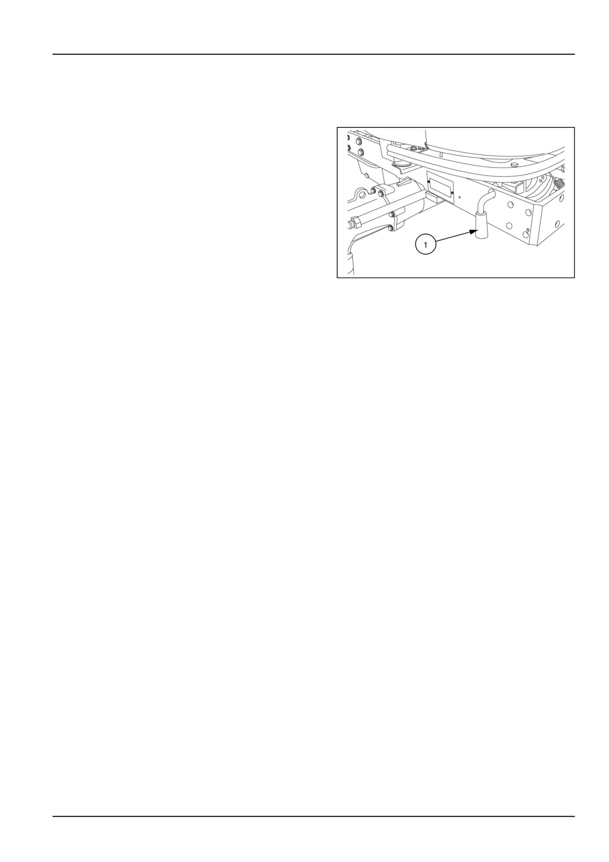
As viewed from the front of the tractor:
1. To raise the hood, move the latch release lever (1)
forward and lift the hood to its fully raised position. A
gas shock holds the hood in the fully raised position.
2. To close, lower the hood until it is retained by the latch
mechanism.
NOTE: Keep latch mechanism free of dirt and debris
so latch assembly will operate properly.
NHAC13CT00045AA
1
3-27
4 - OPERATING INSTRUCTIONS
4 - OPERATING INSTRUCTIONS###_4_###
Commissioning the unit
Engine break-in procedure
Your tractor will provide long and dependable service if given proper care during the first 50-hour break-in period.
During the first 50 hours of operation:
1. Avoid "lugging" the engine. Operating in too high a gear under heavy load may cause engine lugging, which is
indicated when the engine will not respond to a throttle increase.
2. Use the lower gear ratios when pulling heavy loads and avoid continuous operation at constant engine speeds.
You will save fuel and minimize engine wear by selecting the correct gear ratio for a particular operation. Operating
the tractor in low gear with a light load and high engine speed wastes fuel.
3. Avoid prolonged operation at either high or low engine speeds without a load on the engine.
4. Check the instruments frequently and keep the radiator and oil reservoirs filled to recommended levels. Daily
checks include the engine oil level, radiator coolant, and air cleaner.
5. After the first 50 hours of use, be sure to perform the maintenance items listed in the maintenance schedule.
4-1
4 - OPERATING INSTRUCTIONS
Power Take-Off (PTO) - Operation
Rear PTO
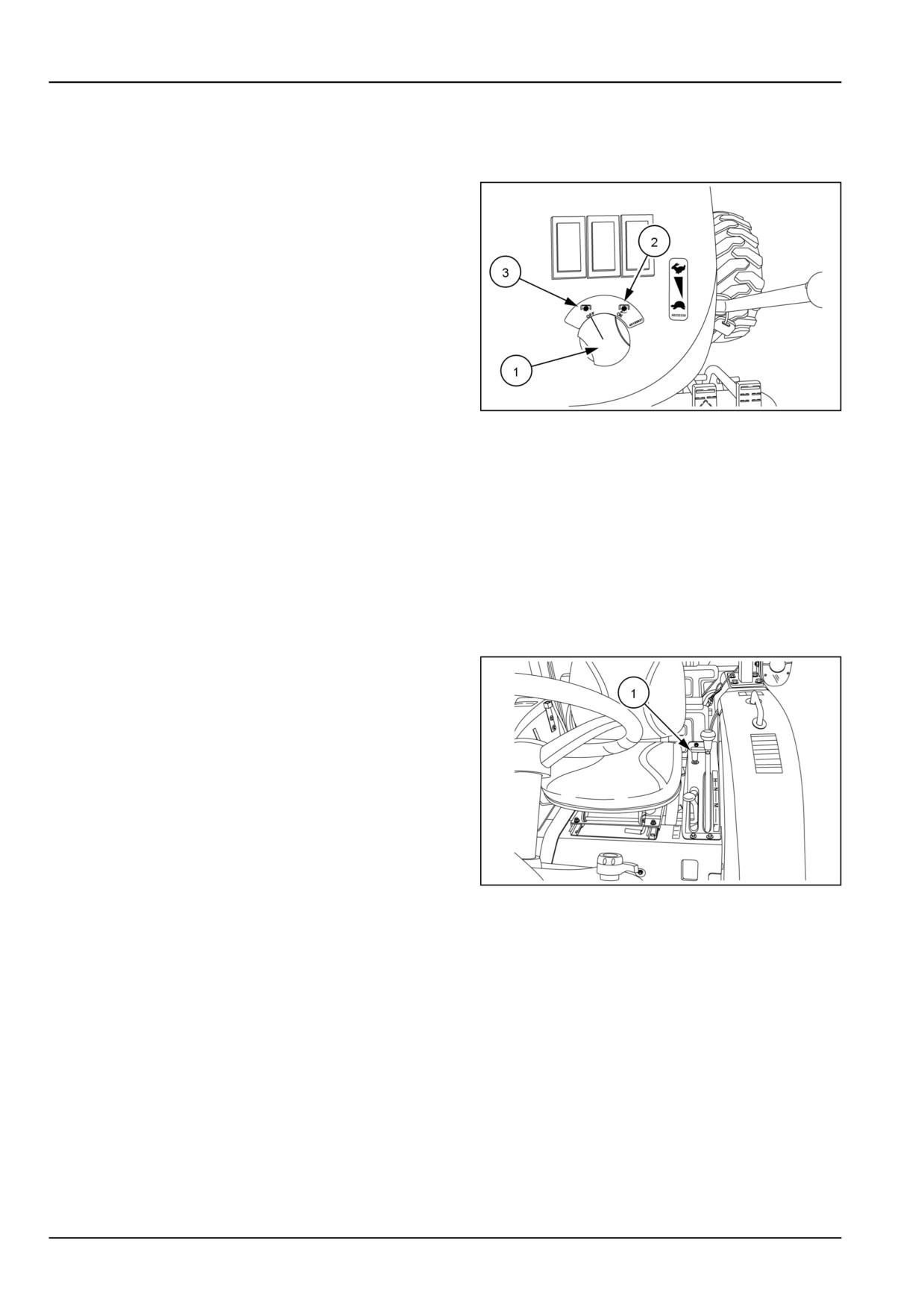
1. To engage the PTO, push the PTO switch (1) down
and turn the switch to the "ON" position (2).
NOTE: When the PTO is engaged the PTO indicator
light will be illuminated on the instrument panel.
2. The PTO system is totally independent of the tractor
ground speed, and the following operations can be
performed.
• The tractor ground travel can be stopped without stop-
ping the PTO.
• Stop the PTO by disengaging the PTO clutch without
stopping the tractor ground travel.
NHIL12CT00670AA
1
3. To disengage the PTO, push down on the PTO switch
and the switch will automatically return to the "OFF" posi-
tion (3).
NOTE: To obtain 540 RPM rear PTO speed, the engine
speed is 2510 RPM.
Mid PTO
Mid Power Take-Off (PTO) is standard equipment on Hy-
drostatic-Transmission (HST) and optional on mechanical
transmission tractors.
1. To engage the mid PTO, pull up on the mid PTO lever
(1) push down on the PTO switch and turn the switch
to the "ON" position.
NOTE: When the mid PTO is engaged the rear PTO
will also be engaged. The mid PTO cannot be en-
gaged separately.
NOTE: To obtain 2000 RPM mid PTO speed, the en-
gine speed is 2545 RPM.
2. To disengage the mid PTO, push the mid PTO lever
(1) down to the "OFF" position and , push down on the
PTO switch and the switch will automatically return to
the "OFF" position.
NHIL12CT00772AA
2
NOTE: To start the engine the mid PTO lever must be
in the down (disengaged) position and the PTO switch
in the "OFF" position.
4-2
4 - OPERATING INSTRUCTIONS
Rear PTO operation without operator present
WARNING
Entanglement hazard!
Before operating stationary Power Take-Off (PTO) equipment, do the following: apply the parking
brake, place all controls in the neutral position, and block all four wheels.
Failure to comply could result in death or serious injury.
W0336A
NOTICE: The engine will shut off in approximately two seconds if the operator leaves the seat without the main trans-
missions shift lever/shuttle shift lever in the neutral position, HST pedals not in the neutral position or the Mid PTO
lever not in the "OFF" position.
NOTE: The Mid PTO cannot be operated without an operator present in the seat.
To operate the rear PTO without the operator in the seat the following operations must be performed:
• Main transmission shift/Shuttle shift lever in NEUTRAL position.
• Park brake engaged.
• Mid PTO in "OFF" position (if equipped).
• Rear PTO in "ON" position.
The alarm will sound when the following conditions are present:
• Rear PTO is engaged.
• Operator not in the seat.
• Park brake disengaged.
4-3

4 - OPERATING INSTRUCTIONS
Rear three-point hitch
The tractor's three-point linkage is used to attach three-
point mounted equipment which is usually PTO operated,
such as rotary mowers, tillers, flail mowers, snowblowers,
etc. The three linkage points are the two lower lift arms
and the top link.
The three-point linkage has adjustable sway bars (1) to
control lateral movement of the lift arms. The length of
the top link (2) and the height of the left-hand and right-
hand lift arms (3) and (4) can be adjusted to ease the
attachment of implements and to level the implement after
attaching.
NHIL12CT00803AA
1
4-4
4 - OPERATING INSTRUCTIONS
Attaching three-point hitch equipment
WARNING
Entanglement hazard!
Before attaching or detaching equipment or changing the Power Take-Off (PTO) shaft: 1) Apply the
parking brake. 2) Move all controls to neutral and PTO control knob to the disengaged position. 3)
Stop the engine and remove the key. 4) Wait for the PTO shaft to stop turning before leaving the cab.
Failure to comply could result in death or serious injury.
W0323A
NOTICE: When attaching mounted or semi mounted implement to the three-point linkage, ensure that there is ade-
quate clearance between the implement and the rear of the tractor. The clearances in the raised position should be
checked by raising the implement carefully with the position control lever. With the implement fully raised there must
be at least 100 mm (4 in). Clearance between the implement and the nearest part of the tractor.
Most implements can be attached to the tractor as follows:
1. Position the tractor so that the lower link hitch points are level with and slightly ahead of the implement hitch pins.
Carefully bring the tractor rearwards to match the tractor and implement hitch points. First attach the left-hand
lower link, then by adjusting the leveling box, attach the right lower link.
2. Lengthen or shorten the top link until the implement mast pin can be inserted through the mast and upper link of
the implement.
3. When detaching the implement, the procedure is the reverse of attaching. The following hints will make detaching
easier and safer.
• Always park the implement on a level, firm surface.
• Implement should be supported so that it cannot tip or fall when detached from the tractor.
• Always relieve all hydraulic pressure in any remote cylinders before detaching.
Left-hand lift rod adjustment
WARNING
Crushing hazard!
Before disconnecting a lift rod from the lower link, lower the attached implement to the ground, and
stop the engine. Make sure the attached implement is correctly supported and no pressure remains
in the hydraulic system before removing the lift rod securing pins.
Failure to comply could result in death or serious injury.
W0034A
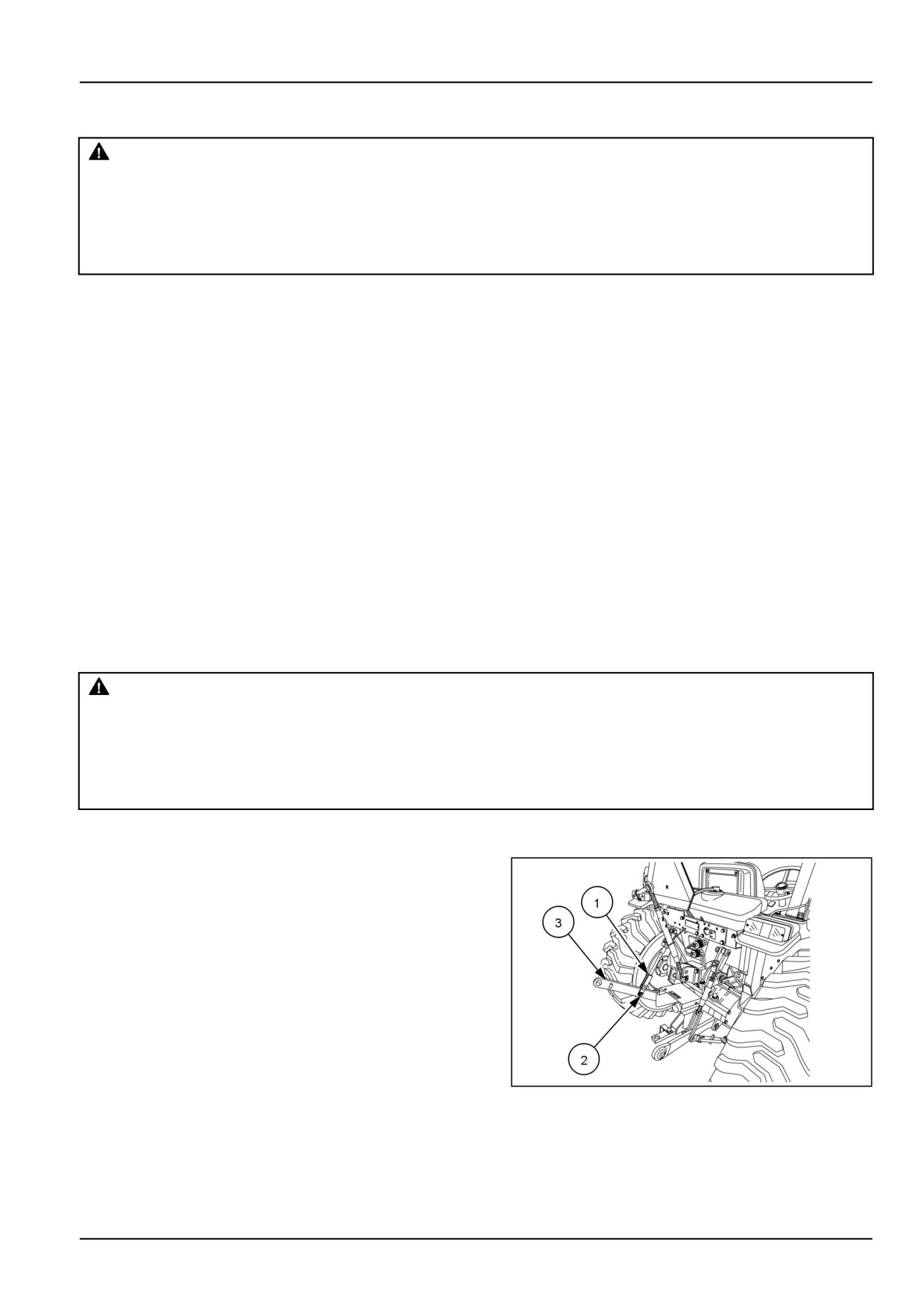
NOTICE: The left-hand lift rod (1) is adjustable but must be removed from the lift arm before length can be changed.
To lengthen or shorten the left-hand lift rod (1) remove the
bolt and nut (2) from the lift rod and lower link (3). Rotate
the top half of the lift rod clockwise to reduce the length
and counter-clockwise to increase the length.
NHIL12CT00803AA
1
4-5
4 - OPERATING INSTRUCTIONS
Right-hand lift rod adjustment
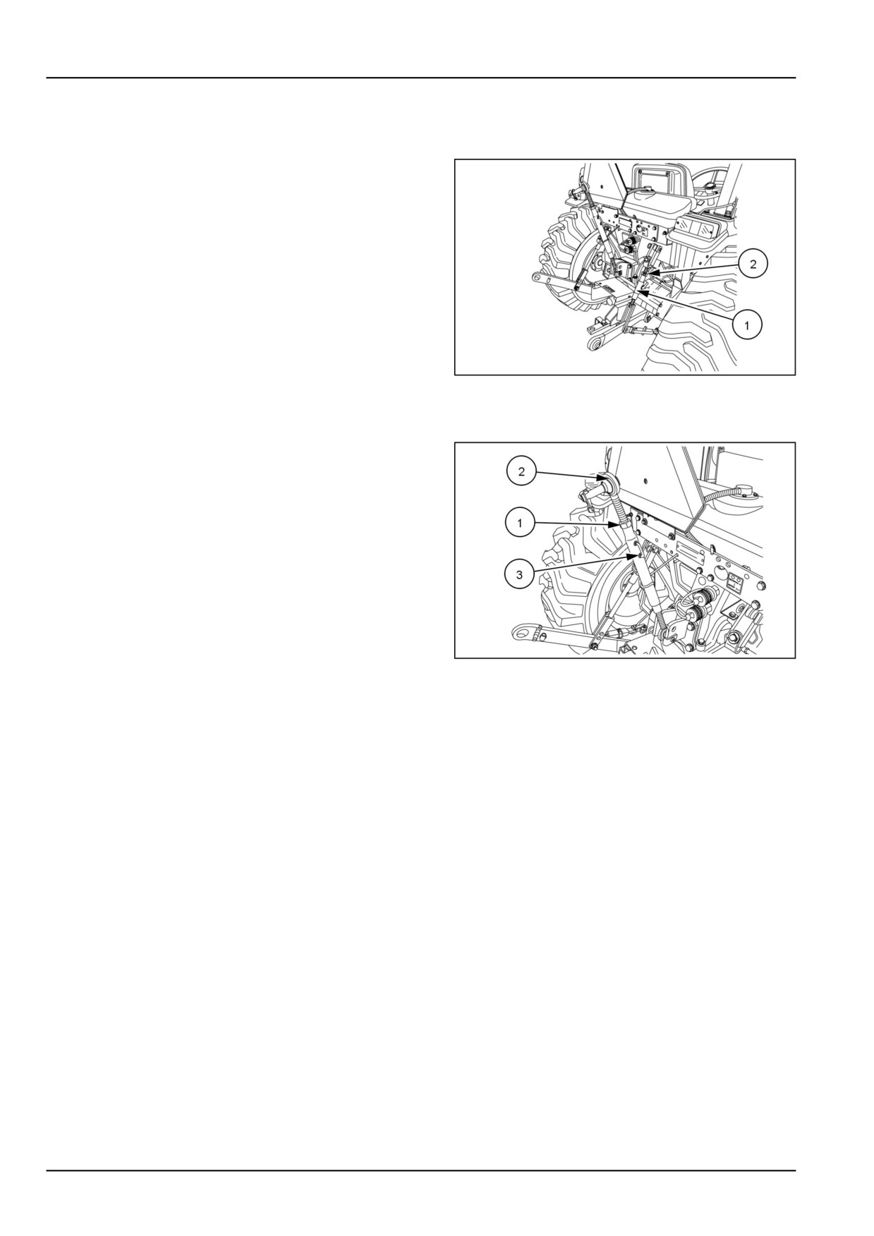
NOTICE: The right-hand lift rod is readily adjustable even when connected between the lift arm and lower link.
To lengthen or shorten the right-hand lift rod (1) loosen jam
nut (2) and rotate lift rod clockwise to reduce the length
and counter-clockwise to increase the length.
NHIL12CT00803AA
2
Top link adjustment
To adjust the top link length, loosen the jam nut (1). Hold
the link end (2) and rotate the handle (3) on the sleeve to
lengthen or shorten the top link. After adjustment tighten
the jam nut to prevent unwanted rotation of sleeve when
in use.
NHIL12CT00805AA
3
4-6