New Holland BR6080. OPERATOR’S MANUAL (2011) - page 4
7 - MAINTENANCE
Inch Lock Nuts, All Metal (Three optional
methods)
Grade Identification
Grad-
Corner Marking
Flats Marking
Clock
e
Method (1)
Method (2)
Marking
Method (3)
Grad-
No Notches
No Mark
No Marks
eA
Grad-
One
Letter B
Three Marks
eB
Circumferential
Notch
Grad-
Two
Letter C
Six Marks
eC
Circumferential
20090268
4
Notches
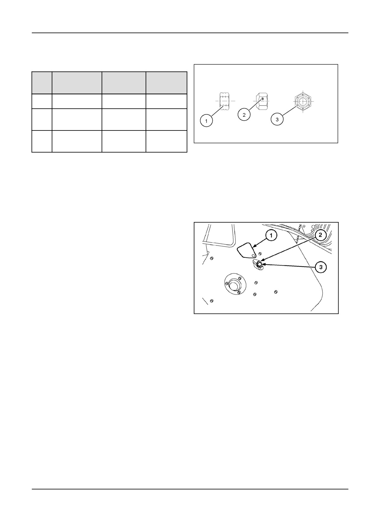
Cam adjustment Cam follower replacement [25802250]
Pickup cam follower bearing replacement
When pickup rotation becomes jerky, inspect the pickup
for a failed pickup cam follower bearing. The pickup cam
track is located on the right-hand side of the pickup.
To replace a cam bearing, proceed as follows:
1.
Pivot cover (1) to gain access to the cam follower
bearing (2) through the hole in the pickup frame.
2.
Rotate the machine (with a bar through the PTO
shaft yoke) until the bearing faces the access hole.
3.
Remove nut (3) using a socket wrench.
4.
Install a new bearing and tighten the nut to 72 N·m
(637.3 lb in) torque.
NOTE: When installing a cam follower bearing, always
make sure the bearing is trailing the respective pickup tine
bar in the direction of rotation of the pickup. If the bearing
ZIL10FCRB730AAA
1
is leading or going ahead of the tine bar, severe damage
may result.
ATTENTION: Inspect that the bearing carrier bolt shows
no signs of damage or wear. If this is the case, replace
the bolt as well. Remove the most right pickup tine guard
to gain access to the bolt.
7 - 7
7 - MAINTENANCE
Pick up Flotation - wide pickup [25802292]
Wide pickup
For adjustment of the pickup gauge wheels, flotation and
windguard, refer Working Operation Section.
Pickup flotation
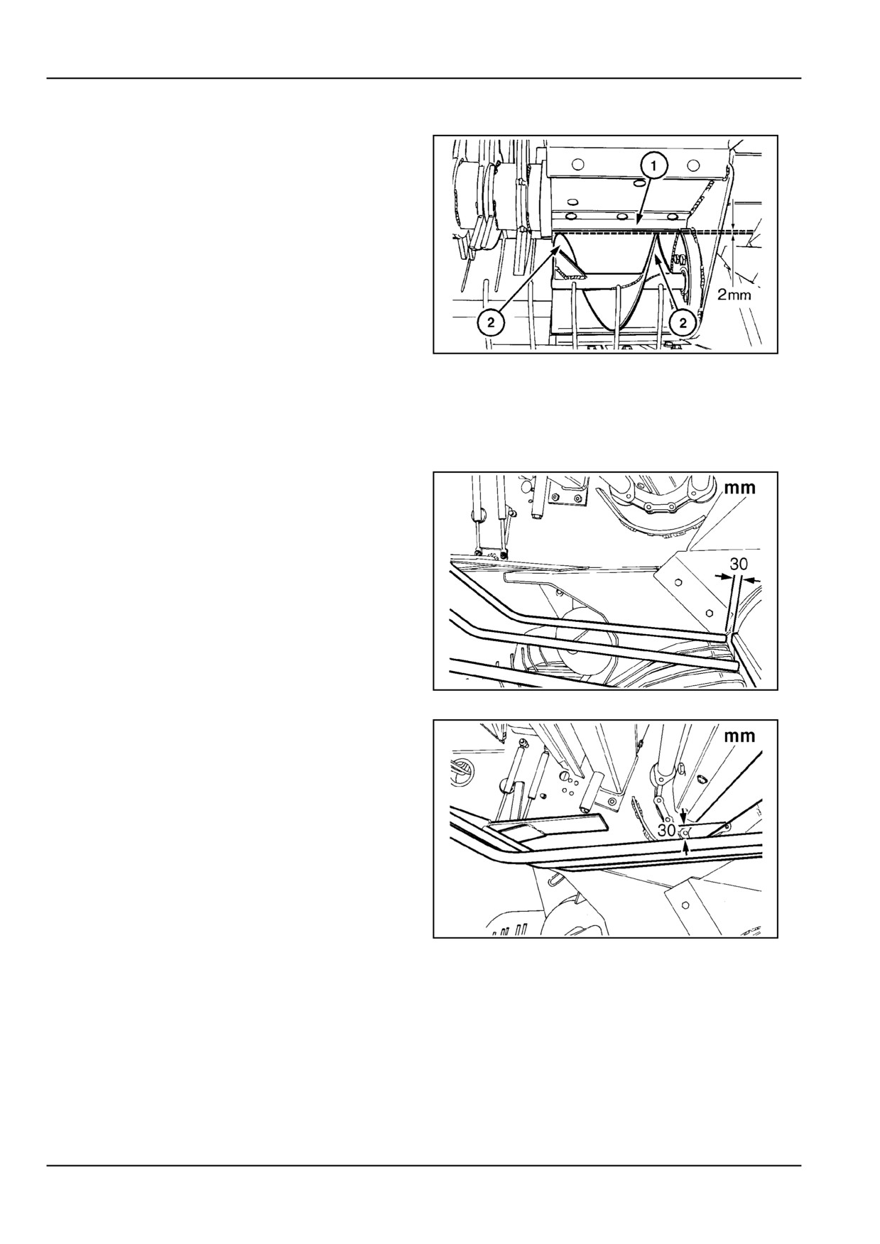
Adjust the auger stripper plate (1) (on both sides of the
pickup) at 2 mm (0.1 in) from the auger flights (2). Slide
the plate back or forth in its mounting slots.
ZIL10FCRB582AAA
1
Windguard [25802482]
Second windguard
With the windguard in the lower position adjust to obtain a
clearance of 30 mm (1.2 in) between the windguard tine
edges and the feeder floor.
ZIL10FCRB841AAA
1
With the windguard in the uppermost position adjust the
center to obtain a clearance of 30 mm (1.2 in) between
the windguard tines and the conveyor bars (conveyor bar
in lowest position).
ZIL10FCRB840AAA
2
7 - 8
7 - MAINTENANCE
Cam adjustment Cam follower bearing replacement [25802593]
Pickup cam follower bearing replacement
When the pickup rotation becomes jerky, inspect the
pickup for a failed pickup cam follower bearing.
The pickup drive and cam are located on the left-hand
side of the machine.
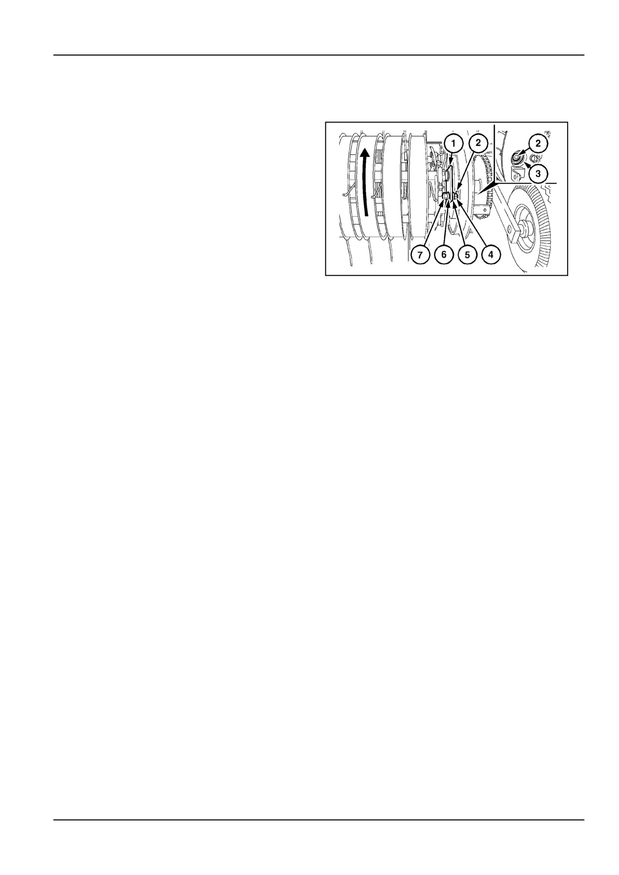
To replace a cam follower bearing, proceed as follows:
1.
Remove the bolts from the guard. Slide the guard
forwards to take if off. The pickup may have to be
lifted a little for ground clearance.
2.
A hole (3) is provided in the side of the pickup to
allow for replacement of the cam follower bearing
(2).
ZIL10FCRB822AAA
1
3.
Use the slug wrench on the feed rotor shaft to rotate
the baler until the bearing faces the access hole.
4.
Remove the wide pickup guard closest to the pickup
side sheet. Remove the nut and extract the bearing
through the access hole. Pay attention not to loose
the washers on each side of the tine bar crank arm
(1):
•
Thick washer (5)
5.
Reinstall the components in reverse order of disas-
sembly.
Securely tighten nut (7) whilst holding counter nut
(4).
Minimum torque: 72 N·m (53.1 lb ft).
NOTE: When installing a cam follower bearing, always
make sure the bearing is trailing the pickup tine bar in the
direction of rotation of the pickup. If the bearing is leading
or going ahead of the tine bar, severe damage may result.
7 - 9
7 - MAINTENANCE
Twine Wrapper [25802796]
Twine tension
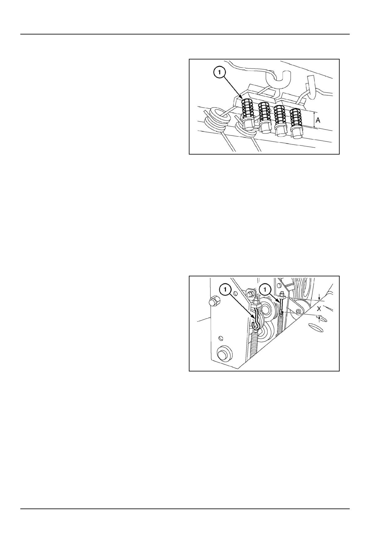
Adjust the four compression springs (1) equally to an ef-
fective spring length A = 50 mm (2.0 in) for polypropylene
750 m/kg twine. Decrease the twine tension with thicker
twine, increase with thinner twine.
Correct twine clamp tension should result in a pull of 20 -
50 N (4.5 - 11.2 lb) required to pull the twine from the end
of the twine tubes with:
•
The spreader hooks in the middle position.
•
Pulling the twine through the twine feed opening,
from the bale chamber (under the raised tailgate).
ZIL10FCRB793AAA
1
NOTE: The twine tension is too high when difficulty is ex-
perienced in starting the twine to wrap around the bale.
It may be necessary to readjust the tension when chang-
ing twine, such as from plastic to sisal.
In case of troublesome twine starting, always check for
correct twine routing first.
NOTE: The twine tension is too light when the twine starts
slipping over the pattern pulley.
Twine Installation [25802849]
Twine feed rolls
Adjust the tension spring bolts (1) to a length (from nut to
eye) of:
X = 62 - 64 mm (2.4 - 2.5 in)
Excessive tension on the feed rolls may crush the twine
and cause stiff rotation of the feed rolls.
Insufficient tension on the feed rolls will make the rolls slip
on the twine at wrap cycle start. This could lead to twine
breakage.
ZIL10FCRB794AAA
1
7 - 10
7 - MAINTENANCE
Feed rolls
ZIL10FCRB060FAA
2
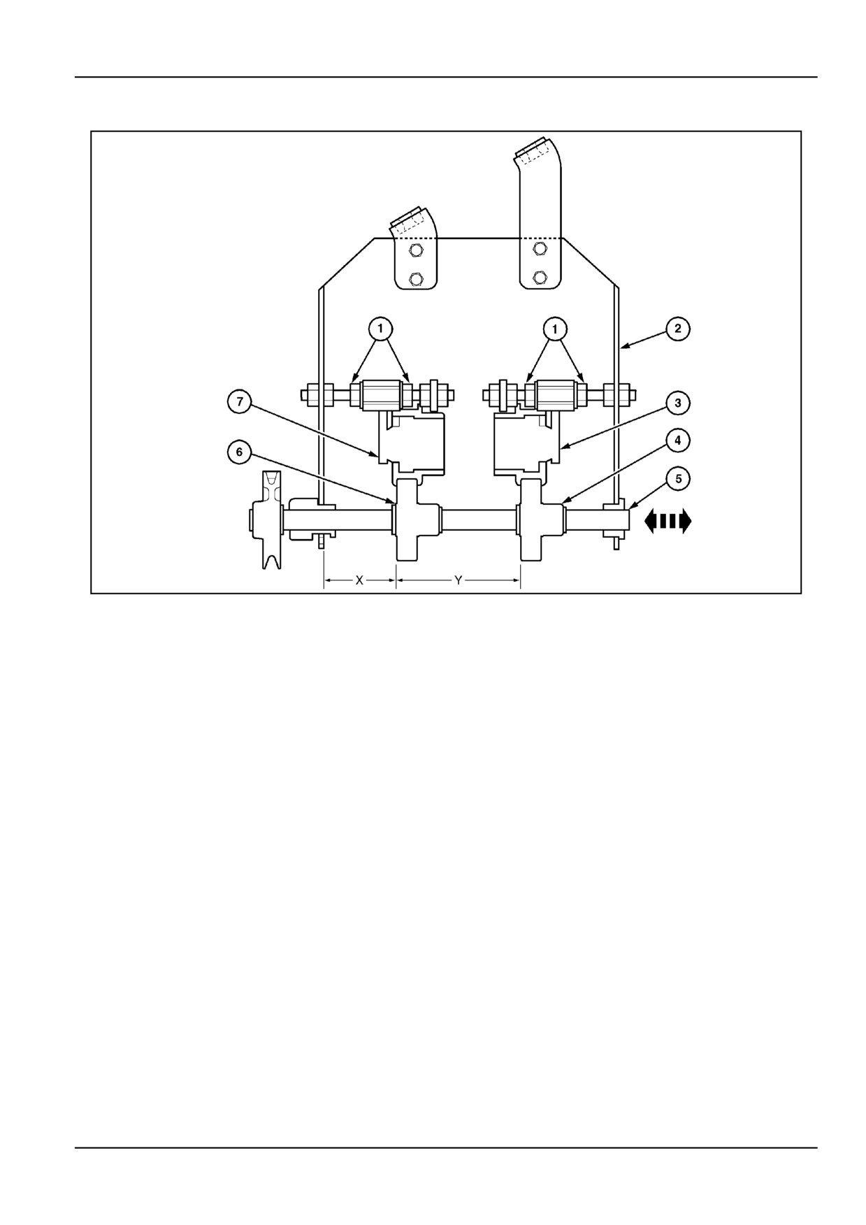
To align the upper feed rolls (3) and (7) over the lower feed
rolls (4) and (6), proceed as follows:
1.
Adjust the left upper feed roll (7) (which is close to
the drive belt) with nuts (1) to obtain a distance X
= 69 - 71 mm (2.7 - 2.8 in) between the wrapper
support frame (2) and the left board of the feed roll.
2.
Adjust the right upper feed roll (3) with nuts (1) to
obtain a distance Y = 119 - 121 mm (4.7 - 4.8 in)
between the left board of the left upper roll race and
the left board of the right upper roll race.
3.
The lower feed rolls (4) and (6) are fixed on the drive
shaft (5), which can be moved left-right a few mil-
limeters to align the upper and lower feed rolls.
7 - 11
7 - MAINTENANCE
Spreader plates [25802882]
Spreader drive chain tension
1.
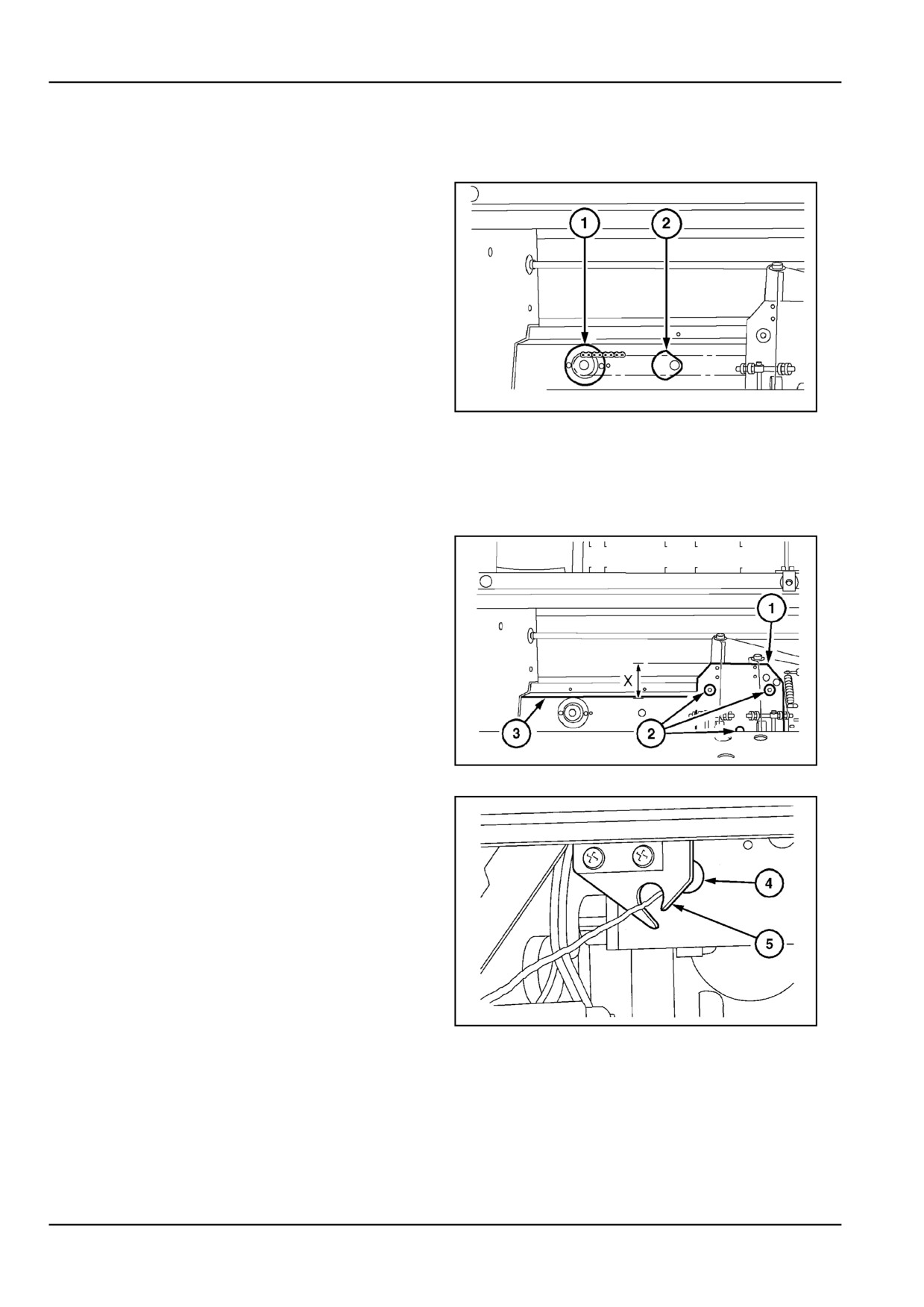
Check the tension of the spreader drive chain
through the access hole behind the spring-loaded
cover (2).
2.
Take up any slack of the spreader drive chain by
moving the adjustable sprocket bearing carrier (1)
to the outside.
Do not over tension the chain to prevent the wrapper drive
from becoming stiff.
ZIL10FCRB795AAA
1
Twine Installation [25802933]
Feed roll module height
To obtain correct picking up of the running twines by the
spreader hooks (5) (Figure 2 in 1-28) as they pass in front
of the metal eyelets (4) (Figure 2 in 1-28), adjust a dis-
tance X = 79 - 81 mm (3.1 - 3.2 in) between the upper
edge of the feed roll module (1) and the support beam
(3). Loosen the bolts (2) and lower/lift the feed roll mod-
ule. Adjust the module parallel to the support beam.
ZIL10FCRB796AAA
1
NOTE: View is from the inside.
ZIL10FCRB797AAA
2
7 - 12
7 - MAINTENANCE
Twine Wrapper Knife [25802974]
Twine cutting knives
WARNING
Personal Protective Equipment
(PPE) re-
quired.
When assembling, operating, or servicing the
machine, wear protective clothing and PPE
necessary for the particular procedure. Some
PPE that may be necessary includes protec-
tive shoes, eye and/or face protection, hard
hat, heavy gloves, filter mask, and hearing
protection.
Failure to comply could result in death or se-
rious injury.
W0353A
ZIL10FCRB728AAA
1
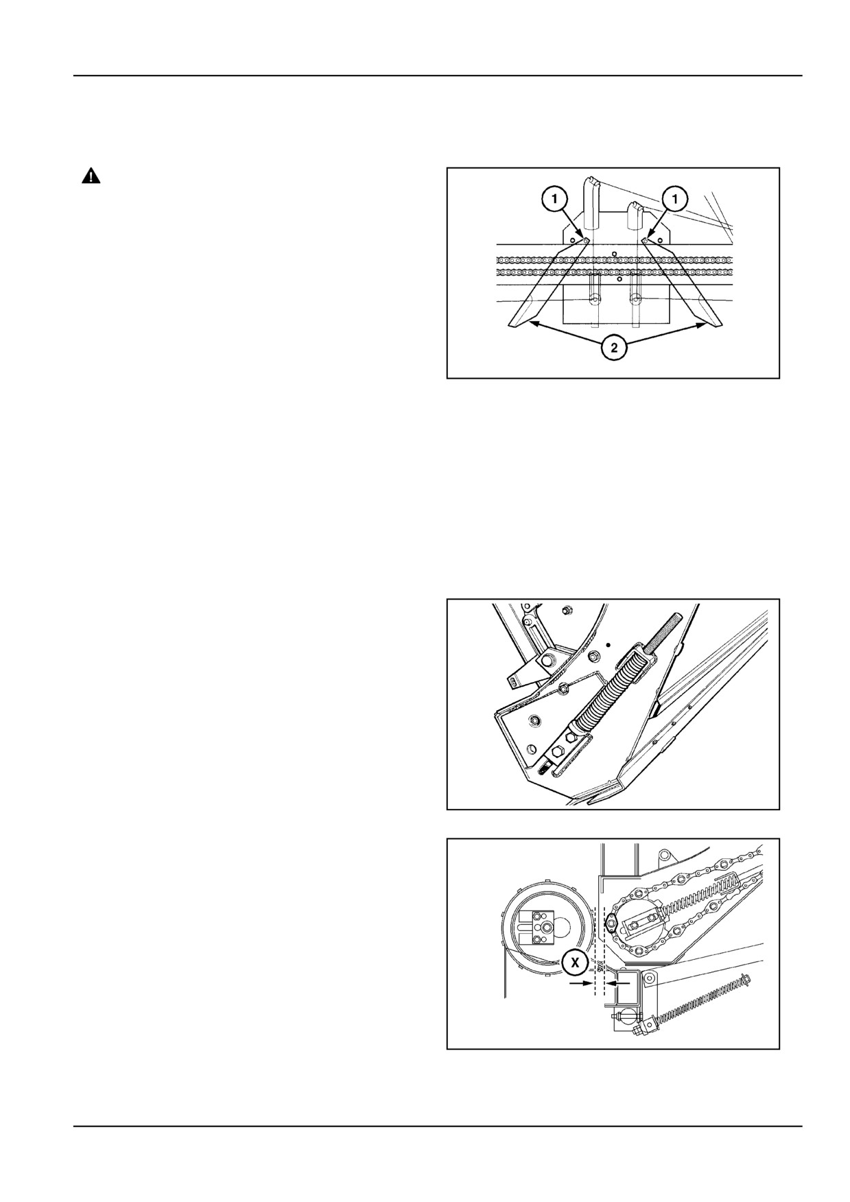
Inspect and sharpen the twine cutting knives (2) every
1000 bales or whenever the twine tails become frayed.
Sharpen the knives from the chamfered side with a whet-
ting stone or a flexible emery cloth disc.
NOTE: When reinstalling the knives on the machine,
make sure to locate them in the most centred holes (1),
for good position and inclination of the cutting edge.
Conveyor Adjustments [25803474]
Conveyor chain tension
The bar and chain conveyor is spring-loaded to automat-
ically keep it under correct tension at all times. Manual
tensioning is not required.
ZIL10FCRB817AAA
1
The stretch of the chain will gradually reduce the distance
(X) between the conveyor bars and the floor roll. This
distance should not be below (X) = 20 mm (0.8 in). A too
big a distance will increase losses over the rear of the floor
roller, particularly during the twine wrap cycle. Periodically
check this distance, remove the plate on the axle behind
the floor roller and observe from under the baler, tailgate
closed:
•
After first 100 bales made
•
Thereafter, every 500 bales.
Should distance (X) become less than 20 mm, then the
floor roll has to be moved forward. Contact your dealer
ZIL10FCRB823AAA
2
for assistance.
7 - 13
7 - MAINTENANCE
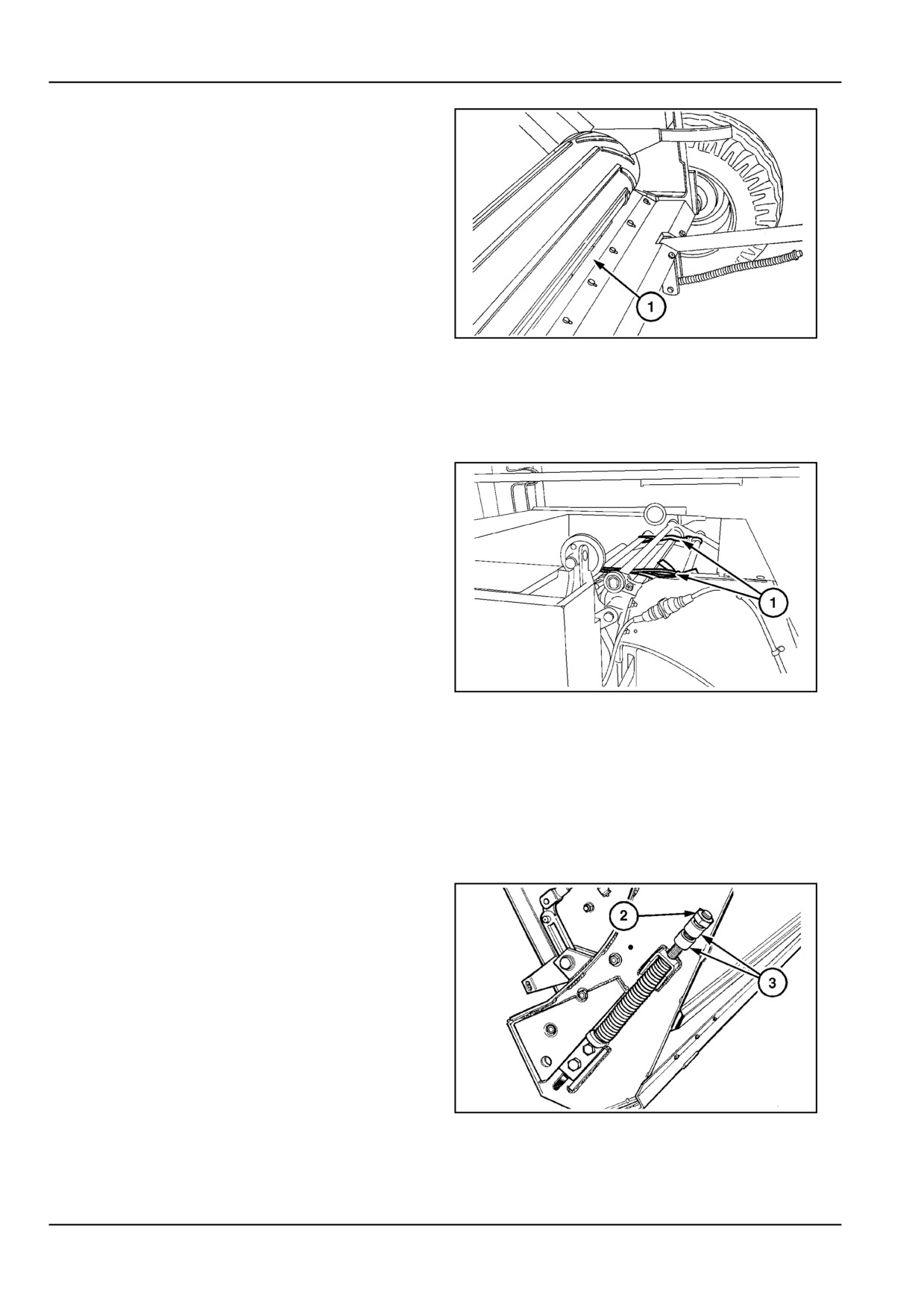
Keep scraper (1) close to the floor roller at all times to
minimize losses.
ZIL10FCRB833AAA
3
Conveyor Adjustments [25803815]
Conveyor bearings and bars
Inspect the bearings for wear or failure at regular inter-
vals. Excessively bent bars (over 20 mm deflection in the
middle) should be straightened immediately.
ZIL10FCRB824AAA
1
To service the conveyor, such as opening the chains, re-
placing bearings or bars, proceed as follows:
1.
Turn the baler by means of a bar through the PTO
yoke to expose the selected component at the top
of the baler, as shown in Figure 1. Do not forget to
remove the bar.
2.
Remove the tailgate guards on both sides.
3.
Obtain appropriate length pieces of 1" tube (3) (In-
side Diameter. 21 mm (0.8 in) and M20 nuts (2) to
compress the tension springs on both sides so as to
obtain slack on the conveyor, as shown in Figure 2.
4.
Install straps (1) as illustrated in Figure 1 to hold
the conveyor together in case the chains have to be
opened.
5.
The component can now be serviced:
•
To replace a bearing, remove the circlip. Mind
the washers behind the bearing. They take up
the end thrust between the bar holding chain
link, the bearing and the circlip.
ZIL10FCRB818AAA
2
•
To remove or replace a bar, remove the circlip,
the bearing and the washers. Now the chain
link holding the bar can be removed as well,
which opens the chain and frees the bar.
7 -
14
7 - MAINTENANCE
Feeder [25804060]
Breakaway springs
Figure 1
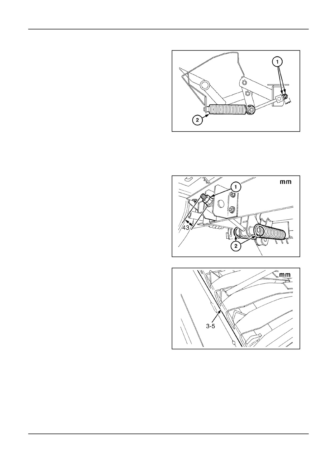
Adjust the feeder overload springs
(2) with nut and
counter nut (1) to obtain a distance of:
X = 41 - 45 mm (1.6 - 1.8 in)
between the rear surface of the block and the threaded
rod end.
Adjustment of feeder fork tines 3 - 4 mm (0.1 - 0.2 in) 3 -
4 mm from frame backbone.
ZIL10FCRB802AAA
1
Feeder [25804371]
Breakaway springs
If removed then reinstall the breakaway springs (2), and
adjust the breakaway link to 43 mm (1.7 in) between
washer and the tip of the rod.
Then fine tune with the nut and counternut at (1) to obtain
a minimal clearance of 3 - 5 mm (0.1 - 0.2 in) between
the feeder tines and the backbone of the feeder frame.
ZIL10FCRB838AAA
1
Minimal clearance of 3 - 5 mm (0.1 - 0.2 in)
ZIL10FCRB839AAA
2
7 - 15
7 - MAINTENANCE
Conveyor Adjustments [25834134]
Conveyor chain
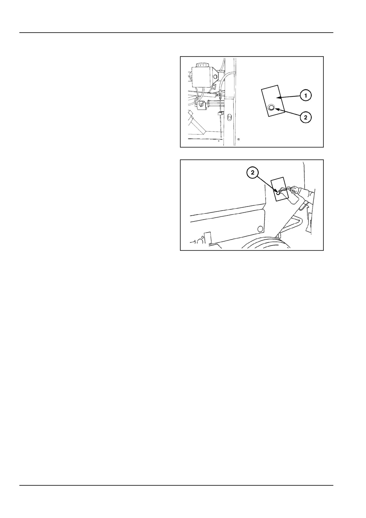
Open the cover (1) to the side and clean the oiling tubes
(2). Feed oil onto the conveyor chains and the conveyor
bar bearings on both sides of the machine.
Oil the conveyor chain through the access hole (2) while
running the machine idle every 10 hours of use and after
storage.
ZIL10FCRB277AAA
1
Lubricate the conveyor chain immediately after operation
while it is still warm and let the machine run idle for a
short period to ensure effective oil penetration resulting
in longer life using these guidelines.
•
Run the machine at low idle speed for oiling the
chain. Ensure there is a second person in the trac-
tor to shut the tractor PTO and engine off in case of
emergency. Engage the tractor handbrake. Close
and latch all baler guards and the tailgate. Keep at
a safe distance from the machine in particular the
ground wheels.
•
Oil at the end of the workday while the chain is still
warm and let the machine run idle for a short pe-
ZIL10FCRB183AAA
2
riod to ensure effective oil penetration, oil both sides
equally.
NOTICE: In abrasive sandy conditions it is better to run
the chains dry (not to oil on a daily basis). However oil
abundantly before and between seasons, storage periods
and prior to starting the new season.
Linkages, threaded rods and pivots
It is recommended to oil all linkages, threaded rods and
pivot points
(including guard pivot points) which may
become stiff from corrosion or dirt, every 200 operating
hours or monthly and every time after cleaning the baler
with water.
7 - 16
7 - MAINTENANCE
Tailgate [25803035]
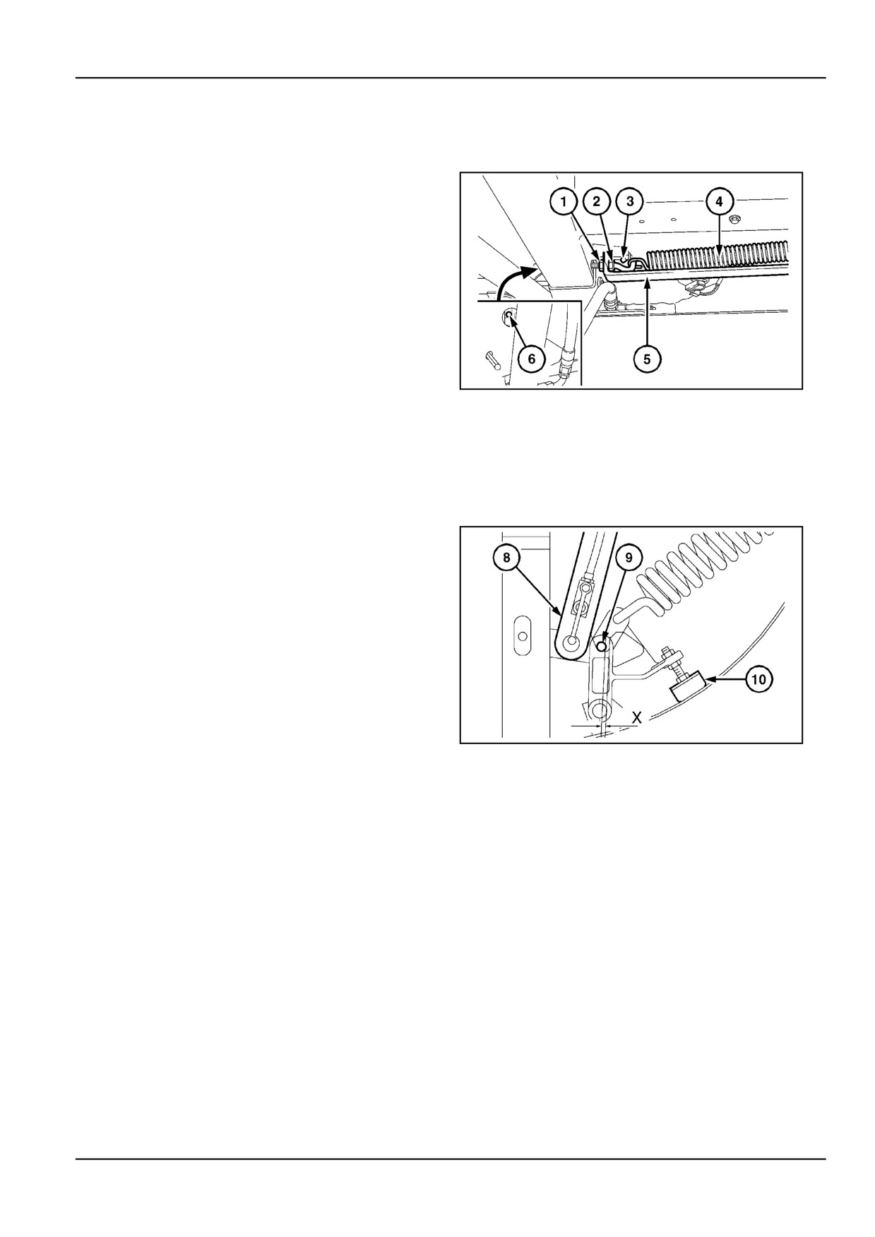
Tailgate latches
When the tailgate latches do not function properly, such
as:
The tailgate opens prematurely, the tailgate fails to open
(latches fail to disengage),
The latch engages or disengages on one side, and not on
the other side, check the following points.
1.
Check that the eyebolt (3) is flat with the latch (the
tailgate is opened to better expose the object).
2.
The tailgate latch springs (4) (on both sides) do not
require adjustment. Regularly verify for possible
failure.
ZIL10FCRB825AAA
1
3.
With the tailgate properly closed (free from crop ac-
cumulation preventing the tailgate to fully close; the
tractor hydraulics in the float position), verify that
latches (8) raise up and positively engage pin (9).
Verify that the tailgate hinges are in good condition
as well.
4.
Adjust each latch individually with links (5) on both
sides of the baler. Adjust links (5) with nut (1) and
jam nut (2) on eyebolt (3).
5.
Verify that the density spring is retracted, the rub-
ber dampers (10) pressed firmly against the tailgate
frame.
Adjust the rubber dampers to obtain a clearance X
= 5 - 7 mm (0.2 - 0.3 in) equally on both sides.
ZIL10FCRB720AAA
2
Bale density [25839611]
Density springs
The springs are adjusted ex-factory for proper field
operation and normally do not require maintenance.
They have a preload of 3.8 kN (854.3 lb) with the bale
chamber closed and empty. If, for any reason, one or
both springs have to be replaced, proceed as follows:
1.
Remove both springs from the baler.
2.
Measure the length (from eye to eye) of the unten-
sioned springs that will be installed on the machine.
7 - 17

7 - MAINTENANCE
3.
Temporarily reinstall the spring fixation plates (2) on
the tailgate, without the shims at (1).
4.
With the tailgate pins (4) properly adjusted (refer
to chapter Tailgate latch adjustments), measure
the distance X between both attaching points of
the spring (rubber dampers (3) in contact with the
tailgate frame).
5.
Now install the longest spring on the side where dis-
tance X was biggest.
Add shims (1) left or right to obtain equal spring ex-
tension left and right (within 2 mm) when the springs
are preloaded.
ZIL10FCRB283AAA
1
Example:
•
One spring is 5 mm longer than the other.
•
Distance X (left) is 2 mm (0.1 in) bigger than dis-
tance X (right).
Solution:
NOTICE: The longest spring must be installed on the
left-hand side and shims to a thickness of 3 mm must
be placed on the right-hand side to obtain equal spring
preload.
Bale density system [25803339]
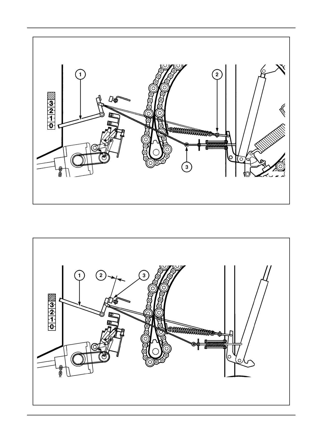
Bale density indicators
Adjust the density indicator cables as shown opposite with
the tailgate closed and latched, and the bale chamber
empty:
NOTE: After removal or replacement of the density and
latch cables, always reattach them in the upper hole on
the indicator.
7 - 18
7 - MAINTENANCE
ZIL10FCRB057FAA
1
•
With the density indicator (1) pointing at "zero" den-
•
With the density indicator pointing at "zero" density,
sity, adjust the density cable bolt (3) to take up the
adjust the latch cable bolt (2) to just take up the
cable slack and then loosen the bolt 4 mm (0.2 in).
cable slack.
ZIL10FCRB061FAA
2
7 - 19
7 - MAINTENANCE
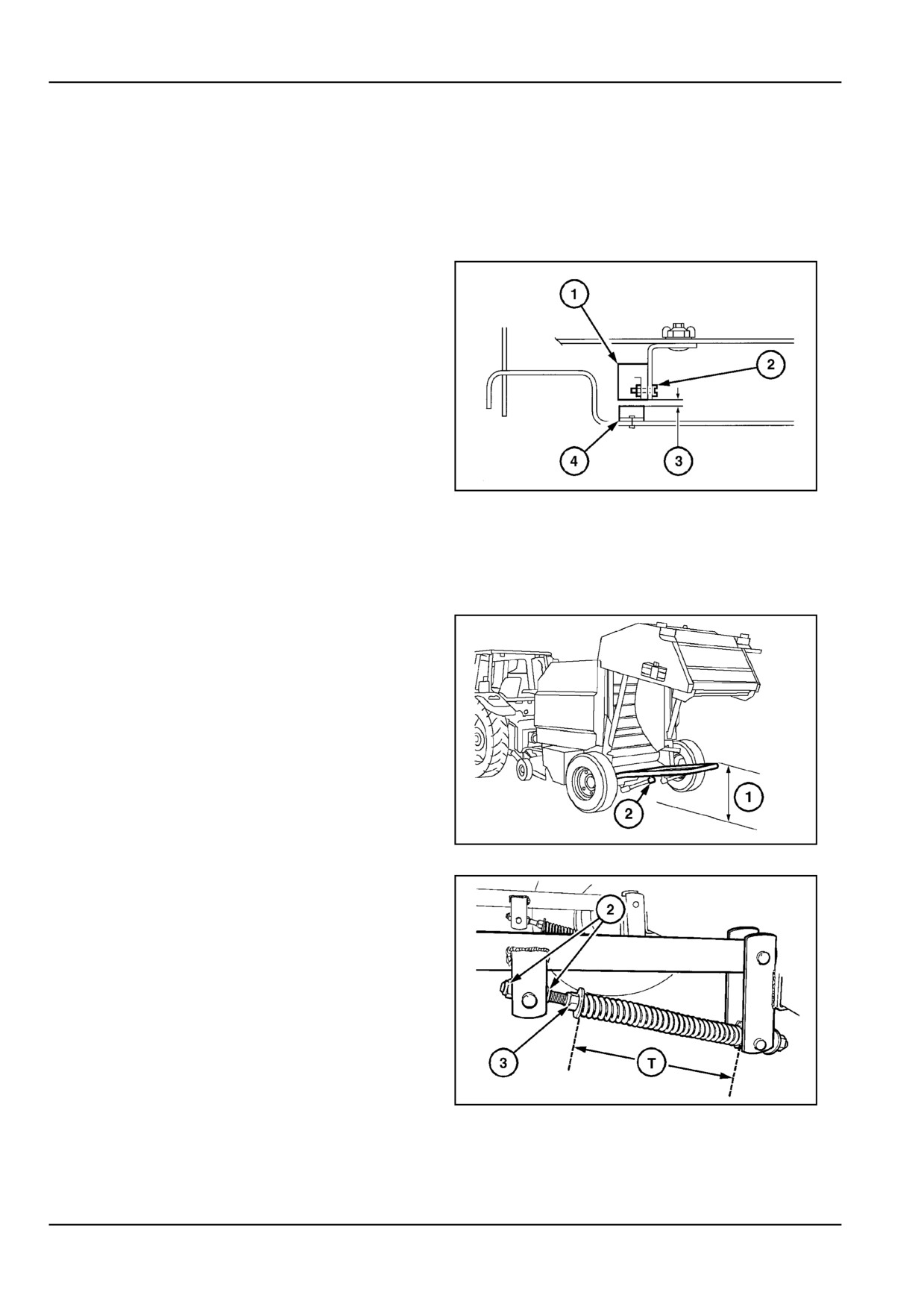
With the tailgate open, and the density indicator (1) fully
raised up, adjust the rubber stop (3) to a clearance of:
(2) = 0 - 2 mm (0.0 - 0.1 in) between the density indicator
and the rubber stop.
Bale Loader Sensor Adjustment [25803376]
Full bale alarm sensor
The full bale alarm sensor (1) makes part of the electric
control box system, supplied on demand.
Adjust the magnet (4) with screws (2) on the left density
indicator for a clearance of (3) = maximum 5 mm (0.2 in)
when the magnet passes in front of the sensor.
ZIL10FCRB798AAA
1
Bale ejection [25803419]
Bale kicker
Depending on local sales policy, the bale kicker will be fit-
ted standard on the machine, or offered as an accessory.
The bale kicker force is adjustable to suit bale weight and
field conditions.
1.
With the tailgate open, the rear bar of the kicker is
set at a height (1) = 620 - 640 mm (24.4 - 25.2 in)
with the nuts and counter nuts (2). This adjustment
must not be changed.
ZIL10FCRB799AAA
1
2.
Also with the tailgate open, the spring is set at a
tension (T) = 448 - 452 mm (17.6 - 17.8 in) with
lock nut (3).
In any case, when adjusting the bale kicker springs to suit
operating conditions, make sure that:
•
The bale kicker will always contact the ground be-
fore the springs are bottoming out, if coil bound too
tight..
•
The bale kicker will bounce excessively during road
transport, springs too light.
ZIL10FCRB816AAA
2
7 - 20
7 - MAINTENANCE
Tailgate [25841477]
Tailgate latch adjustments
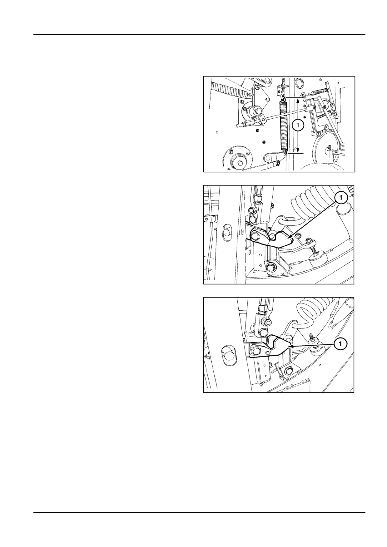
The tailgate latch control spring position and operating
linkage is designed to enable quick reaction and force.
Spring dimension (1) for the baler should be maintained
at 310 mm (12.2 in).
ZIL10FCRB191AAA
1
The latch control spring adjustment will suit most combi-
nations of baler/tractor setup.
However the timing between the tailgate being closed and
the latches being pulled up by the spring force depends on
the back pressure in the return line of the tractor hydraulic
circuit.
Latch shown pulled up and engaged correctly.
ZIL10FCRB189AAA
2
If the latches pull up before the tailgate is fully closed, the
latch will not engage on the lever as shown.
NOTICE: The spring tension will need to be released
evenly on both sides, until the tailgate is fully closed
before the latches pull up.
Latch shown pulled up prematurely and not engaged.
ZIL10FCRB190AAA
3
7 - 21
7 - MAINTENANCE
Latch Mechanical Adjustments
When the tailgate latches do not function properly such
as:
•
The tailgate opens prematurely,
•
The tailgate fails to open (latches fail to disengage),
•
The latch engages or disengages on one side, and
not on the other side,
The following points can be checked and corrected as
necessary:
1.
With the tailgate properly closed (free from crop ac-
cumulation preventing the tailgate to fully close; the
ZIL10FCRB211AAA
4
tractor hydraulic system in the float position), verify
that the tailgate hinges are in good condition as well.
2.
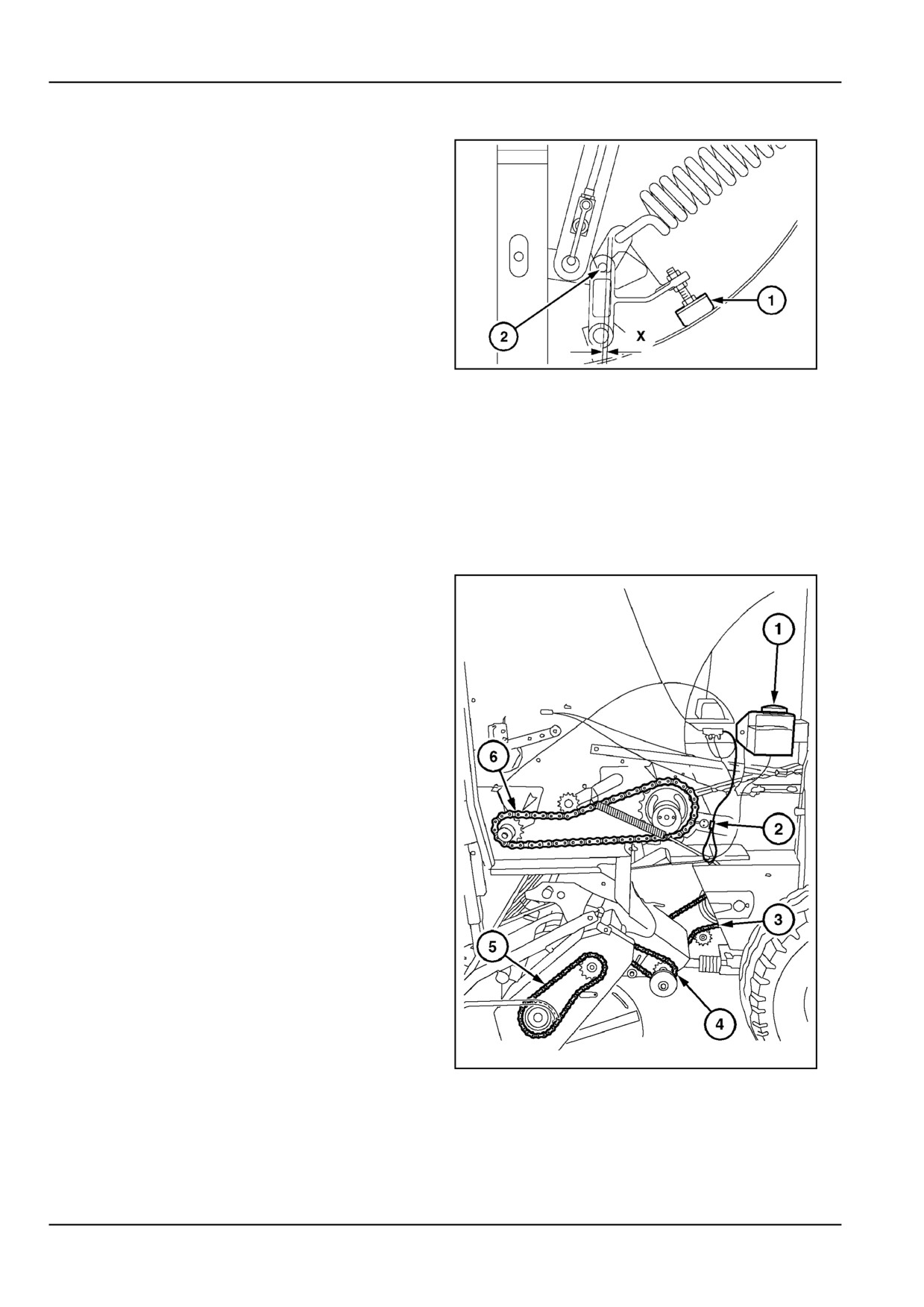
Verify that the density spring is retracted, the rub-
ber dampers (1) pressed firmly against the tailgate
frame. Adjust the rubber dampers to obtain a clear-
ance X = 5 - 7 mm (0.2 - 0.3 in), equally on both
sides.
Automatic oiling system [25804598]
Automatic chain oiler
Automatic lubrication is a factory installed option, but can
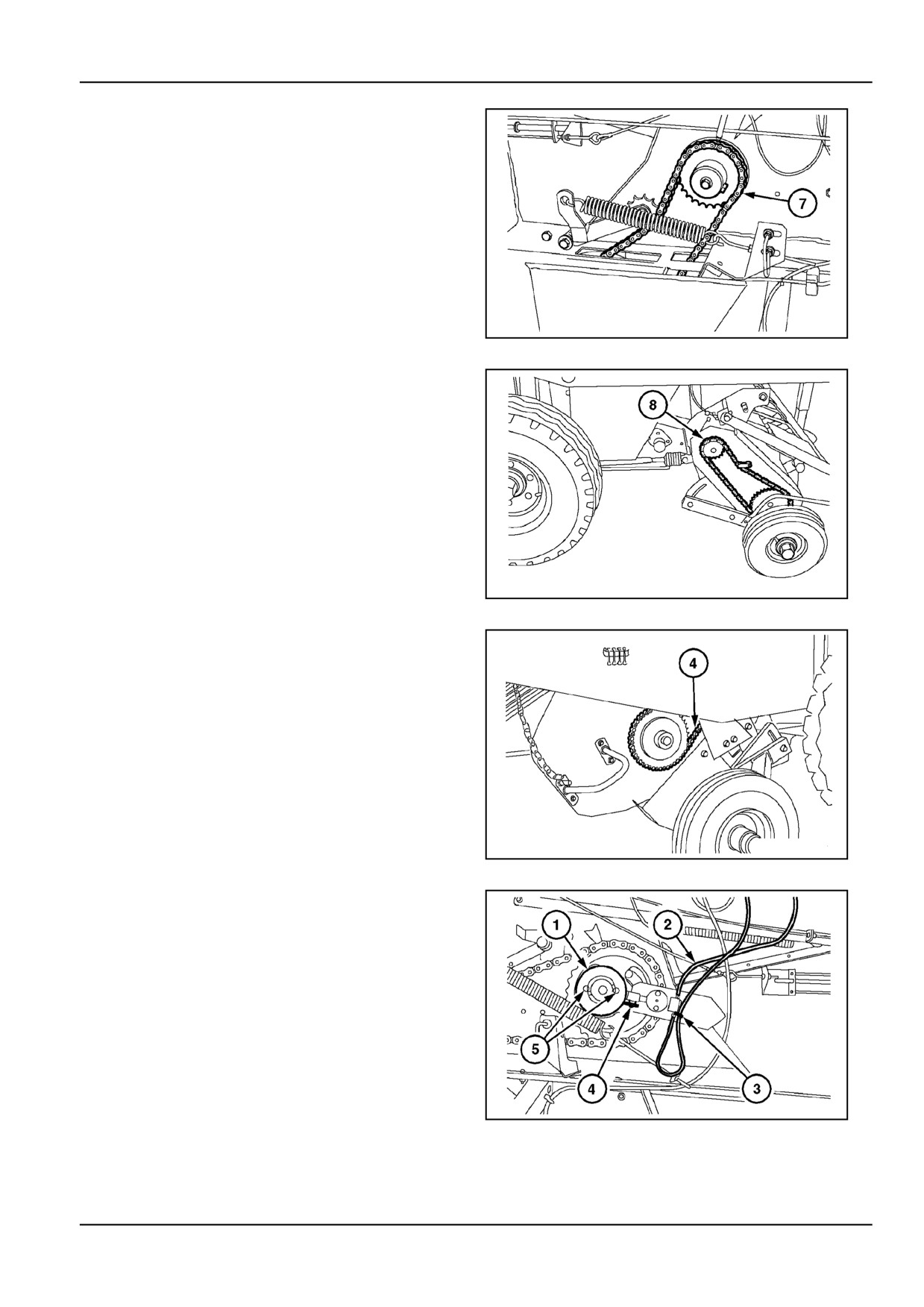
be retrofitted to all machines.
The automatic chain oiler (2) supplies a metered amount
of oil to the following chains:
•
Main drive chain (6) (drives the conveyor chain)
•
Packer drive chain (3) (not on standard pickup mod-
els)
•
Pickup drive chain (4)
•
Pickup reel drive chain (5) (not on standard pickup
models)
ZIL10FCRB014BAA
1
7 - 22
7 - MAINTENANCE
•
Floor roll drive chain (7)
ZIL10FCRB762AAA
2
•
Pickup auger right-hand drive chain (8) (not on stan-
dard pickup models)
ZIL10FCRB764AAA
3
•
Pickup drive chain (4)
ZIL10FCRB763AAA
4
The chain oiler pump is activated by the double eccentric
disc (1) on the conveyor chain drive shaft. During the
upward stroke of the pump cylinder (4), oil flows from the
inlet hose (2) to the pump. During the downward stroke
of the pump cylinder, oil is forced through the outlet hose
(3) to the oiler brushes of the different chains. Each chain
receives a certain amount of oil, determined by the size
of the restrictors located inside the distribution manifold
blocks.
ZIL10FCRB765AAA
5
7 - 23
7 - MAINTENANCE
The oil flow is determined by the eccentricity of the double
disc (1) and is set ex-factory. To increase or reduce the oil
flow rate, loosen the nuts (5) and turn the outer disc over
the inner disc.
The mark on the outer disc will line up with an oil flow rate
number on the inner disc (1 to 7). The higher the number,
the greater the oil flow will be.
The 3 l oil tank must be filled with the recommended hy-
draulic oil.
Manual oiling
On machines not equipped with the automatic lubrication
option, oil the drive chains daily. Prefer to oil the chains
after work, when they are still warm. This will allow better
penetration of the oil. Run the machine slowly at tractor
engine idle speed whilst oiling the chains.
Hydraulic Hose Replacement Interval [30313365]
WARNING
Escaping fluid!
Hydraulic fluid or diesel fuel leaking under
pressure can penetrate the skin and cause
infection or other injury. To prevent personal
injury: Relieve all pressure before discon-
necting fluid lines or performing work on the
hydraulic system. Before applying pressure,
make sure all connections are tight and all
components are in good condition. Never use
your hand to check for suspected leaks under
pressure. Use a piece of cardboard or wood
for this purpose. If injured by leaking fluid,
see your doctor immediately.
Failure to comply could result in death or se-
rious injury.
W0178A
Inspect equipment every 100 hours of usage or every
month, whichever comes first.
Replace hydraulic hose assemblies with your local dealer
for approved components,
If abrasive wear / other damage of the cover exposes the
hose reinforcement braids, or
Oil leakage from the hose assembly, or
After 50,000 bales or 5 years of service life, whichever
comes first.
NOTE: The hydraulic hose is marked with the date of
manufacture and at least must be replaced 6 years af-
ter this date. This allows one year shelf life from date of
manufacture to start of field service.
7 - 24
7 - MAINTENANCE
Wheels and tires [25843485]
The life and performance of the tires depends largely upon
maintaining the correct pressure.
With reference to the tire decal, inflate the tires as follows:
Ground wheels
Standard pickup:
10.0/75 x 15.3 - 8 PR
Implement AW (tubeless)
Inflate to 220 kPa (2.2 bar) in case normal farming prac-
tices prevail. When the baler is doing an unusual amount
of travelling on the road at 40 km/h (typical for contractor
use), increase the tyre pressure to 320 kPa (3.2 bar).
Wide pickup
11.5/80 x 15.3 - 8 PR
Implement AW (tubeless)
Inflate to 207 kPa (2.1 bar) in the case normal farming
practices prevail.
When the baler is doing an unusual amount of travelling
on the road, at 40 km/h (typical for contractor use), in-
crease the tyre pressure to 250 kPa (2.5 bar).
Pickup gauge wheels
4.00 x 6 - 4 PR
Ribbed profile (tube type, tube 4.00 x 6)
Inflate to 290 kPa (2.9 bar).
Wheel nut torque
Check and tighten the wheel lug bolts daily at initial
start-off of the machine until the torque remains stable.
Torque to 380 N·m (280.3 lb ft).
Maximum forward speed on the road should not exceed
40 km/h or not exceed local road speed regulations.
ATTENTION: These tires are designed for and fitted onto
15.3” rims. Ensure to fit replacement tires of the same
size. Do not fit narrower, wider, larger or smaller diameter
tires onto these rims.
Wheels and spindles should be checked every 200 hours.
Wheel nut torque should be checked daily in the first 50
hours and, thereafter, every 100 hours.
7 - 25
7 - MAINTENANCE
Wheels and tires [26070934]
Wheel changing
WARNING
Heavy objects!
Lift and handle all heavy components us-
ing lifting equipment with adequate capacity.
Always support units or parts with suitable
slings or hooks. Make sure the work area is
clear of all bystanders.
Failure to comply could result in death or se-
rious injury.
W0398A
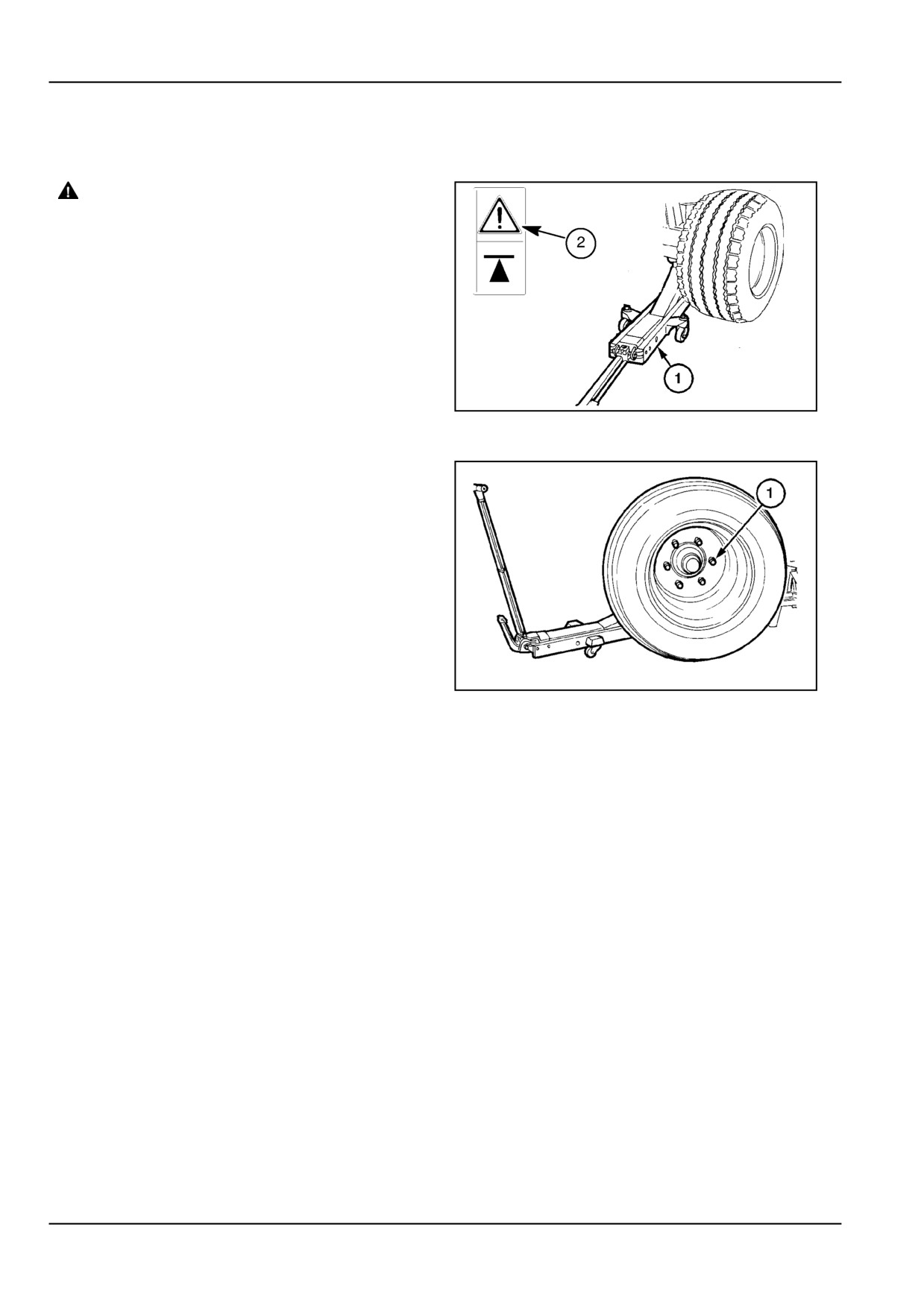
1.
Place a jack of sufficient capacity (1) under the ma-
chine only at the points identified by the decals (2).
Refer to Specifications Section for the weight of the
ZIL10FCRB235AAA
1
balers.
2.
Lift the wheel off the ground and let the weight of the
baler down onto an axle stand where possible.
3.
Remove the wheel nuts (1) and wheel.
Reassemble in reverse order the wheel, tighten the nuts,
rejack, remove the stand, lower the baler, remove jack
and retorque the opposite nuts equally around the rim to
380 N·m (280.3 lb ft).
ZIL10FCRB188AAA
2
7 - 26
7 - MAINTENANCE
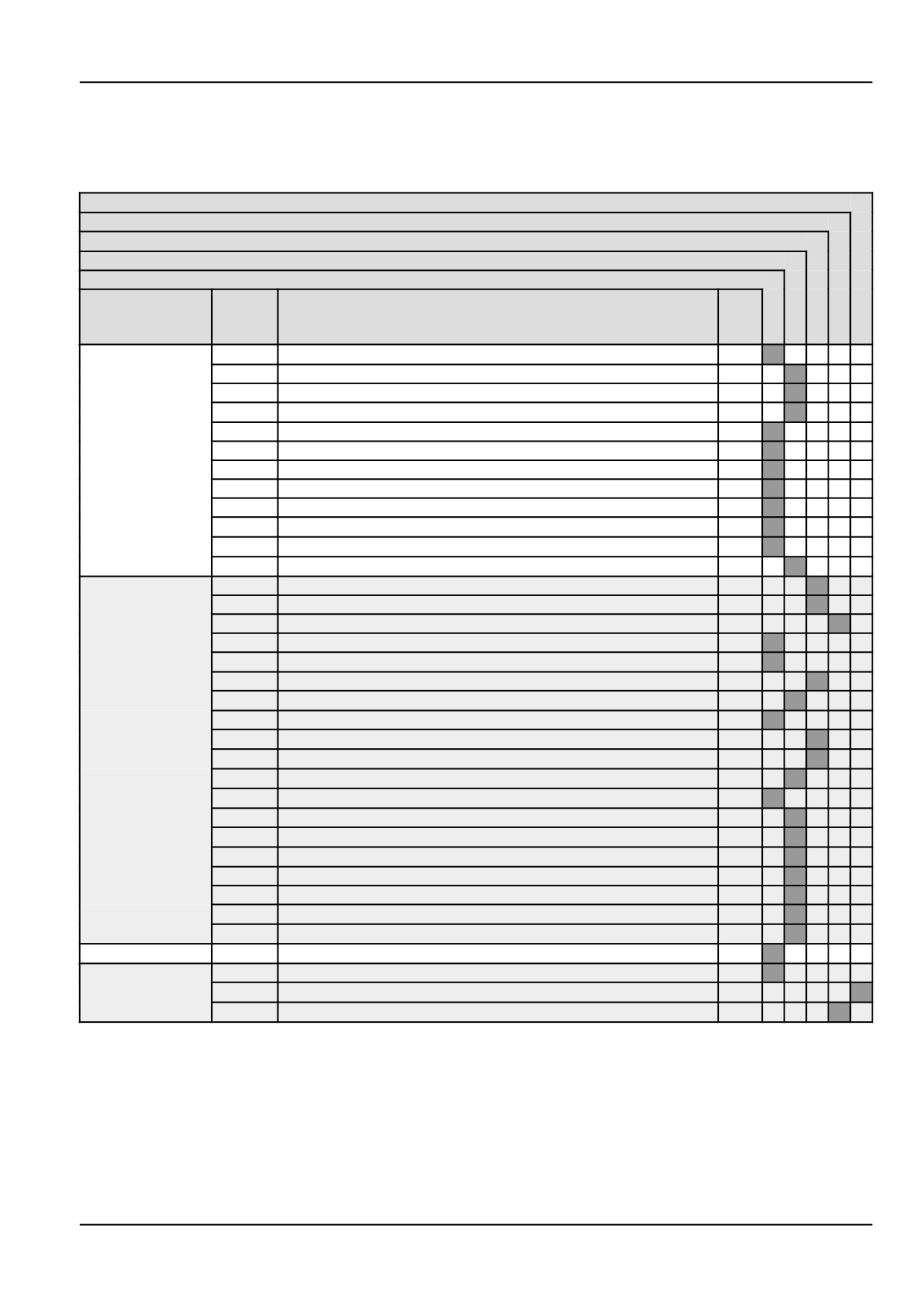
MAINTENANCE CHART
Maintenance Chart [32466823]
Replace
Check
Adjust
Grease
Lubricate
Interval
Page
Maintenance Action
Nb.
Nb.
of
pts
10 hours or daily
7-28
Chain and bar system
X
Service
7-28
Front hitch
X
7-29
Floor Roll Drive Chain
X
7-29
Tailgate
X
7-29
Chain Drive
X
PTO
X
Drive chain lubrication
X
Drive chain lubrication
X
Chain Drive
X
Tailgate
X
Bale ejection
X
Wrapper mechanism
X
50 hours Service
7-30
Drive chains
X
7-30
Drive chains
X
7-31
Gearbox
X
7-31
PTO
X
7-33
Pick up
X
7-34
Drive chains
X
7-34
Bale density
X
7-34
Drive chains
X
7-35
Pick up
X
7-37
Pick up
X
Twine Wrapper
X
7-37
Tailgate
X
7-38
Gearbox
X
7-38
Tailgate
X
Pick up
X
Feeder
X
Feeder
X
Bale shape
X
Wrapper mechanism
X
100 hours Service
7-39
Twine Wrapper
X
1200 hours or 12
7-39
Wheels and tires
X
months Service
Hydraulic circuit oil filter
X
7-39
Hydraulic hoses
X
7 - 27
7 - MAINTENANCE
10 hours or daily Service
Chain and bar system - Lubricate [25807955]
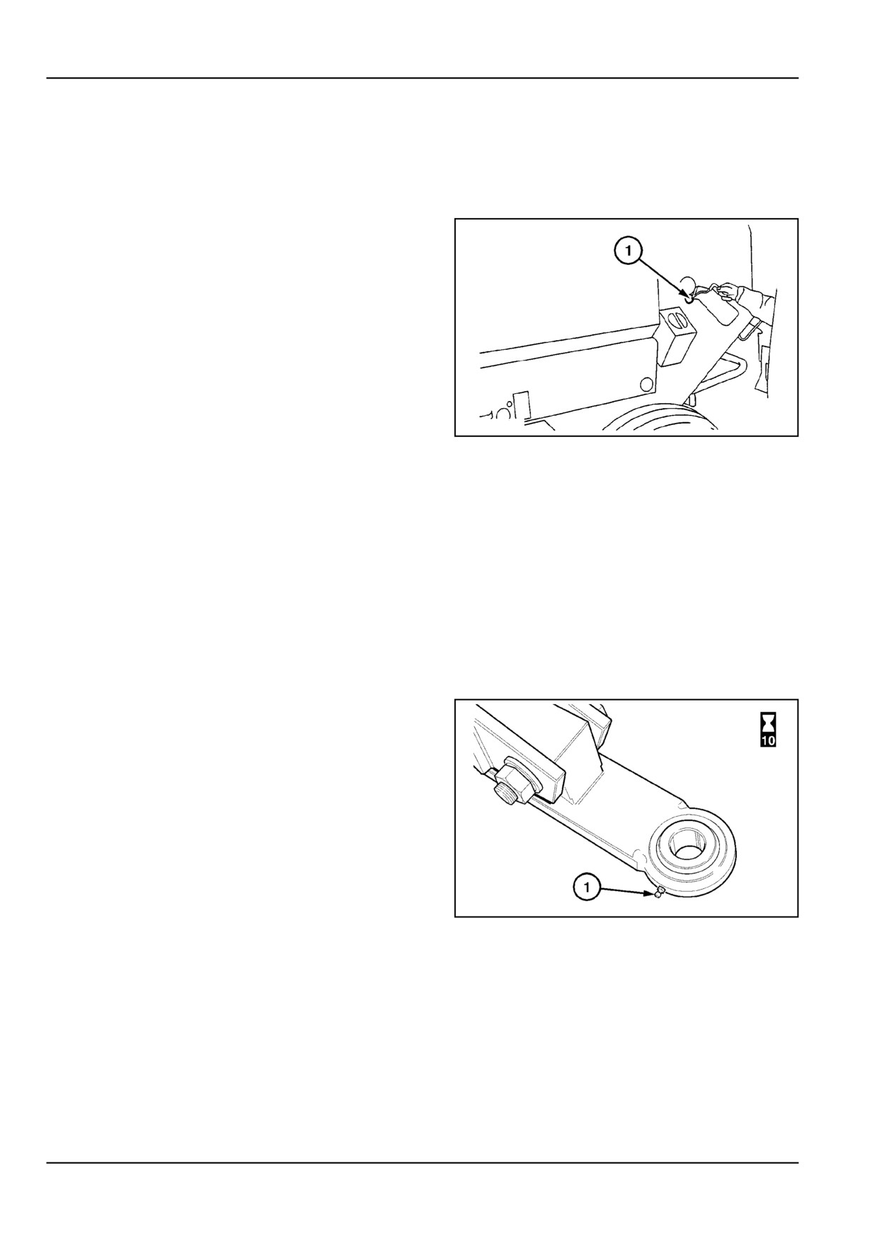
Conveyor chain
Oil the conveyor chain through the access hole (1)
while running the machine idle every 10 hours of use
and after storage.
Lubricate the conveyor chain immediately after oper-
ation while it is still warm and let the machine run idle
for a short period to ensure effective oil penetration
resulting in longer life using these guidelines.
•
Run the machine at low idle speed for
oiling the chain. Ensure there is a second
person in the tractor to shut the tractor
PTO and engine off in case of emergency.
Engage the tractor handbrake. Close and
latch all baler guards and the tailgate.
ZIL10FCRB844AAA
1
Keep at a safe distance from the machine
in particular the ground wheels.
•
Oil at the end of the workday while the
chain is still warm and let the machine run
idle for a short period to ensure effective
oil penetration, oil both sides equally.
NOTICE: In abrasive sandy conditions it is better to run
the chains dry (not to oil on a daily basis). however oil
abundantly before and between seasons, storage periods
and prior to starting the new season.
Front hitch [25808567]
Ball hitch
ZIL10FCRB811AAA
1
7 - 28
7 - MAINTENANCE
Floor Roll Drive Chain [25809072]
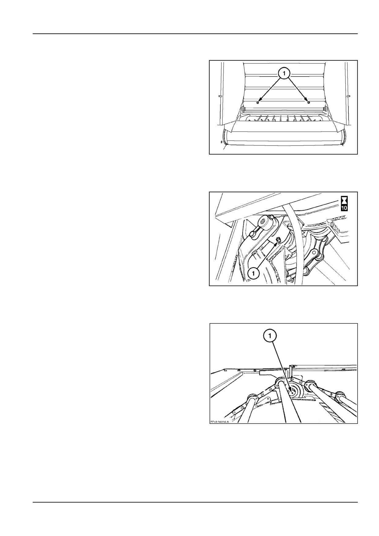
Conveyor drive shaft idlers (2 inside tailgate)
ZIL10FCRB776AAA
1
Tailgate [25809136]
Tail gate hinges
ZIL10FCRB831AAA
1
Chain Drive [25809176]
Right or left bearing for bar chain support
CHAIN
1
7 - 29
7 - MAINTENANCE
50 hours Service
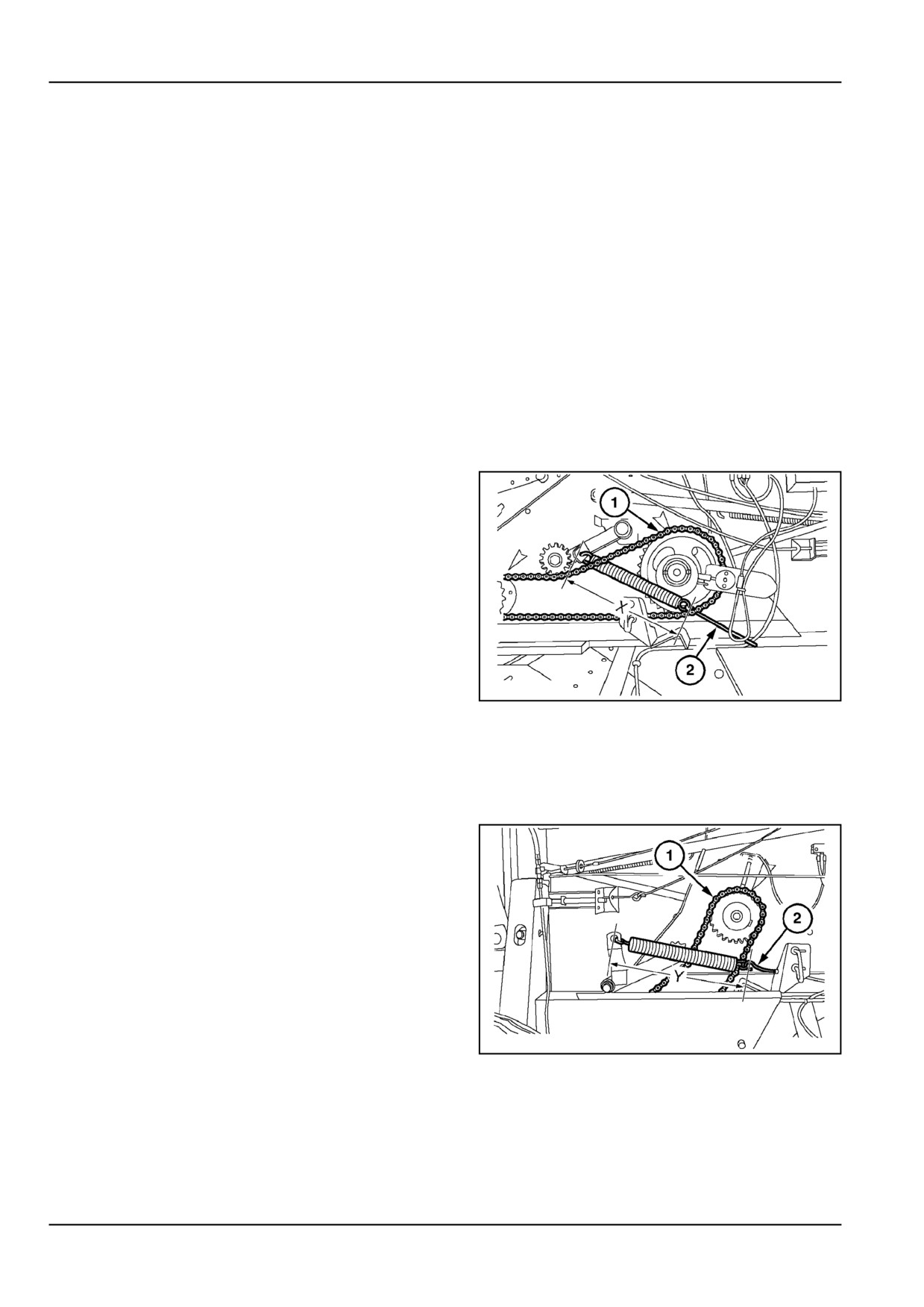
Drive chains [25804953]
Drive chains
Most drive chains are provided with spring-loaded chain
idlers to keep the chains at their optimum tension at all
times.
Periodically check the chains and adjust as required:
•
At first start off, after 50 bales made.
•
Every 100 bales during the run-in period,
until the chain tension stabilizes.
•
Thereafter, on a weekly basis or every 500
bales.
Main drive chain (1)
Spring length (eye to eye):
X = 356 - 360 mm (14.0 - 14.2 in)
Adjust with eyebolt (2).
ZIL10FCRB788AAA
1
Drive chains [25805006]
Floor roll drive chain (1)
Spring length (eye to eye):
Y = 356 - 360 mm (14.0 - 14 in)
Adjust with eyebolt (2).
ZIL10FCRB789AAA
1
7 - 30
7 - MAINTENANCE
Gearbox [25807253]
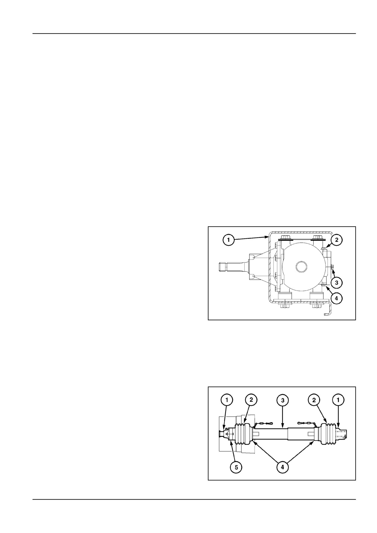
Oil level
Keep the gearbox filled to level plug (3). If necessary, fill
the gearbox through plug (2). Plug (4) is a drain plug.
Always use gearbox oil meeting the following specifica-
tions:
SAE 90 viscosity rating
API GL5M and MIL-L 2104 E classification
When checking the oil level, the baler must be levelled so
that the coach work is parallel to the ground.
NOTE: To check the gearbox oil level, reach over the frame
cross beam (1) to gain access to the level plug.
Oil change
For a new machine after 50 operating hours and thereafter
annually.
Drain the oil through plug (4). Refill the gearbox through
plug (2).
NOTE: Avoid spillage when draining off used oil.
Gearbox capacity 1 l.
ZIL10FCRB278AAA
1
PTO [25807378]
Oiling and greasing
PTO shaft - Standard
The complete PTO driveline must be greased regularly for
smooth power transfer and longer life of the baler driveline
(Standard PTO shown).
ZIL10FCRB767AAA
1
7 - 31
7 - MAINTENANCE
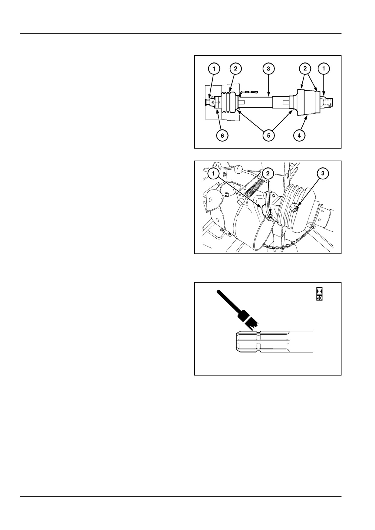
PTO shaft - Wide angle
The baler end PTO universal joint is mostly covered by
safety guarding. To access the rear U - Joint spider lube
fitting (2).
Slide the PTO off the gearbox shaft. The push pin lock on
the rear yoke facilitates this operation.
ZIL10FCRB768AAA
2
Apply grease to areas (1), (2), and (3).
ZIL10FCRB842AAA
3
Tractor yoke
Clean and grease the tractor PTO shaft, the front PTO yoke
and the locking collar before installation of the driveline and
after 50 hours of use.
ZIL10FCRB813AAA
4
7 - 32
7 - MAINTENANCE
Pick up [25807794]
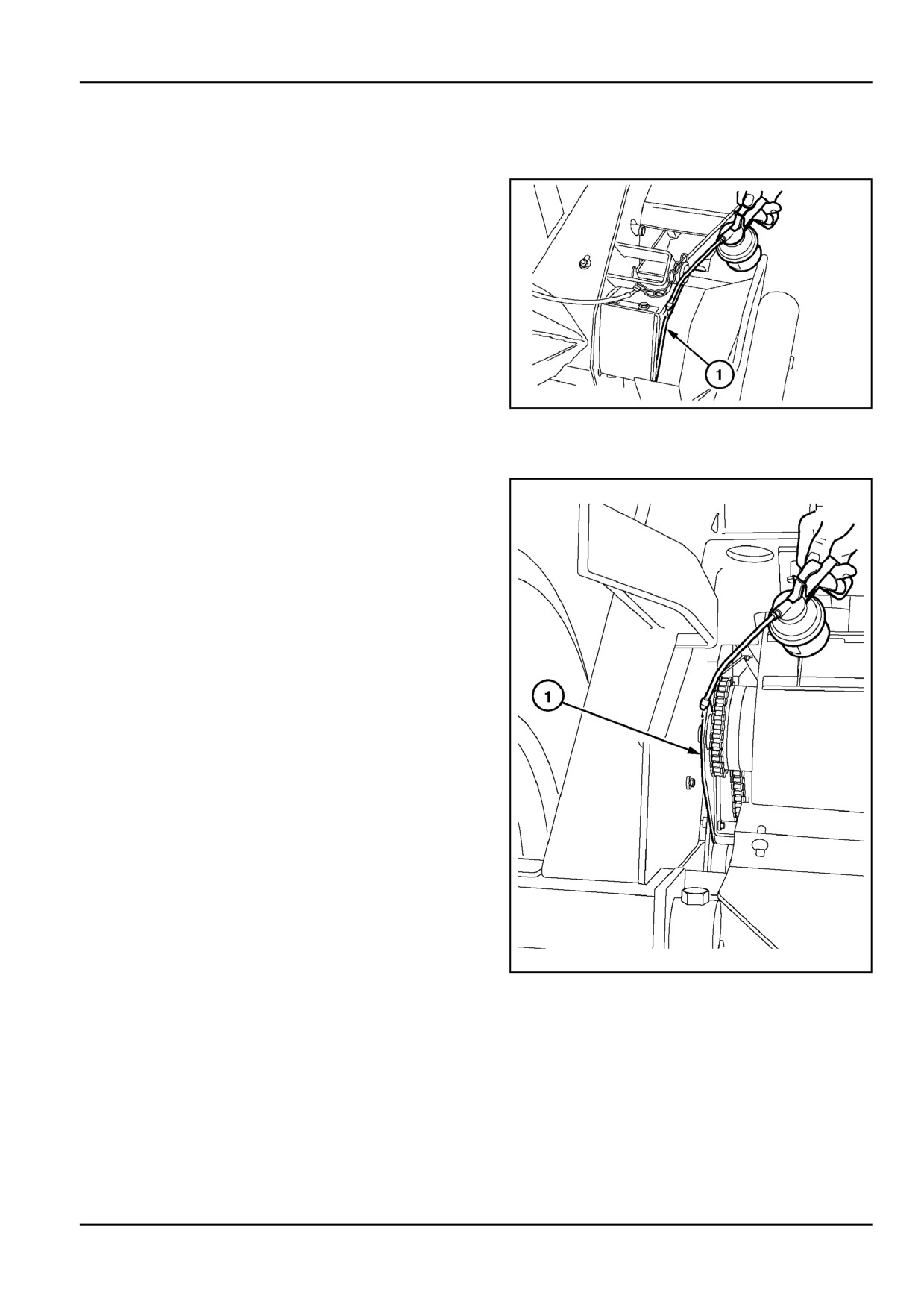
Pickup pivot plates - Standard
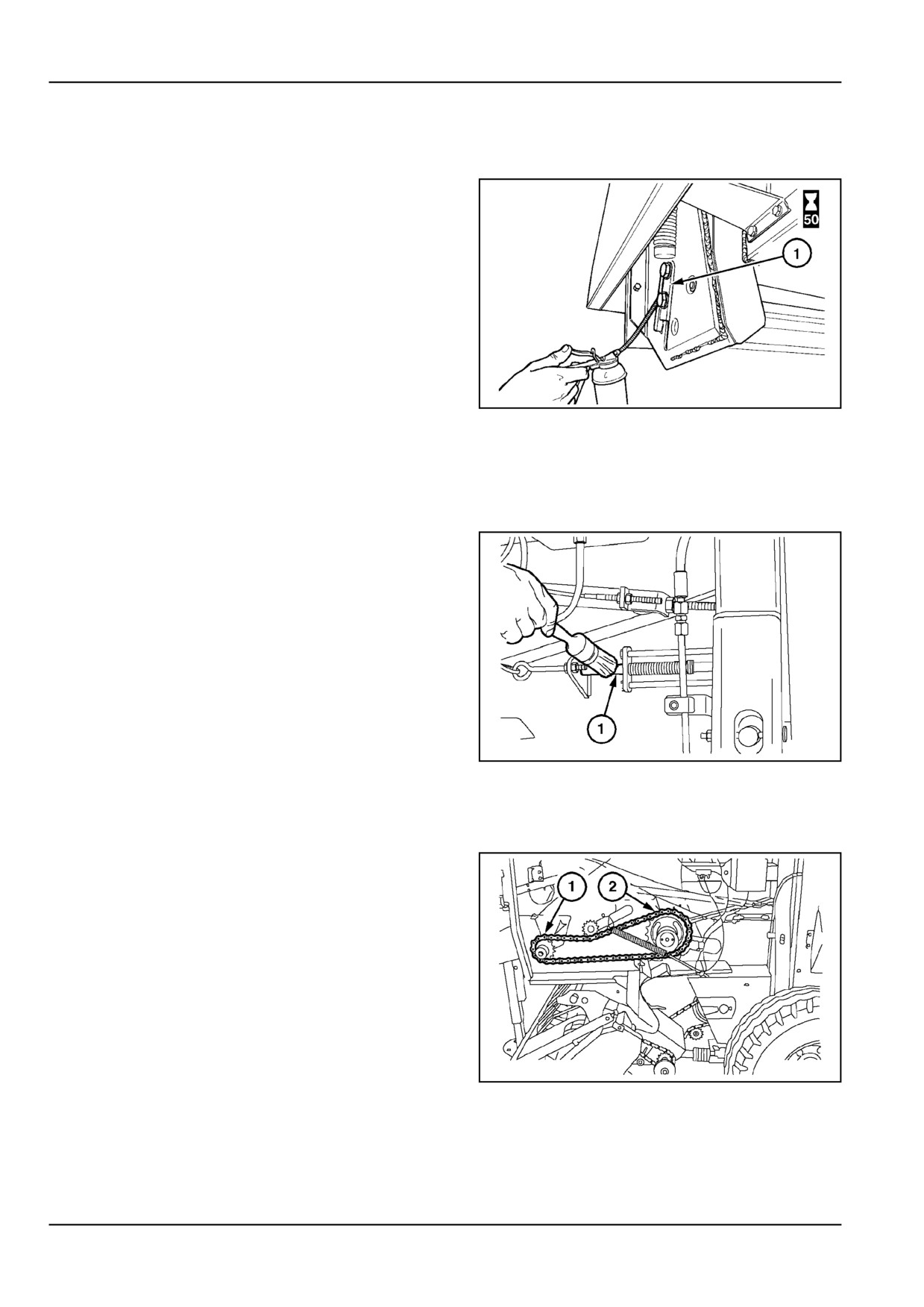
Oil the pickup pivot plates (1) every 50 hours of use and
after storage.
ZIL10FCRB771AAA
1
Pickup pivot plates - Wide pickup
Oil the pickup pivot plates (1) every 50 hours of use and
after storage.
ZIL10FCRB015BAA
2
7 - 33
7 - MAINTENANCE
Drive chains [25808174]
Conveyor chain stretch take-up slots
Clean and oil the left and right-hand conveyor chain stretch
take-up slots (1) every 50 hours of use and after storage.
ZIL10FCRB810AAA
1
Bale density [25808394]
Density indicator rods
Clean and brush grease the left and right density indicator
rods (1) every 50 hours of use and after storage.
ZIL10FCRB773AAA
1
Drive chains [25808966]
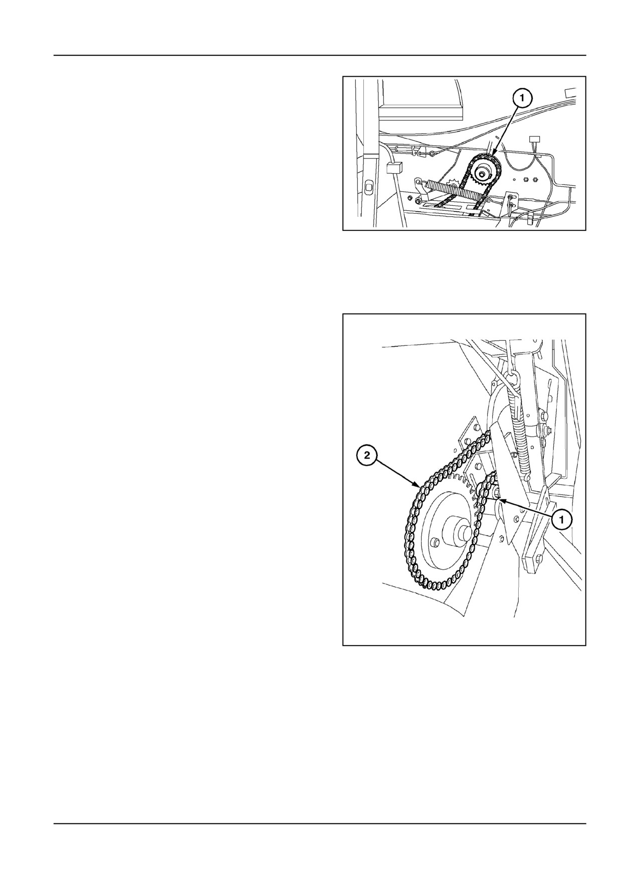
Left-hand side:
•
Gearbox output shaft bearing
•
Conveyor drive shaft bearing
ZIL10FCRB774AAA
1
7 - 34
7 - MAINTENANCE
Right-hand side:
•
Conveyor drive shaft bearing
ZIL10FCRB775AAA
2
Pick up [25809459]
Pickup drive chains
Standard pickup models with guards removed for clarity
Pickup drive chain (2)
Adjust the chain tensioner (1) for a maximum deflection
of 10 mm (0.4 in) in the upper chain span under manual
pressure.
ZIL10FCRB017BAA
1
7 - 35
7 - MAINTENANCE
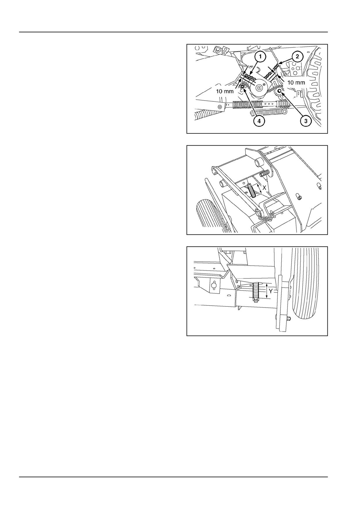
Wide pickup models
Feeder drive chain (2)
Adjust the chain tensioner (3) for a maximum deflection
of 10 mm (0.4 in) in the upper chain span under manual
pressure.
Pickup drive chain (1)
Adjust the chain tensioner (4) for a maximum deflection
of 10 mm (0.4 in) in the upper chain span under manual
pressure.
ZIL10FCRB790AAA
2
Pickup reel drive chain (left-hand side) - Figure 3
Spring length compressed: X = 58 - 62 mm (2.3 - 2.4 in)
ZIL10FCRB791AAA
3
Stub auger drive chain (right-hand side) - Figure 4
Spring length compressed: Y = 58 - 62 mm (2.3 - 2.4 in)
ZIL10FCRB792AAA
4
7 - 36
7 - MAINTENANCE
Pick up [25810137]
Pickup
Standard pickup
For adjustment of the pickup gauge wheels (accessory)
and windguard, refer to Working operations.
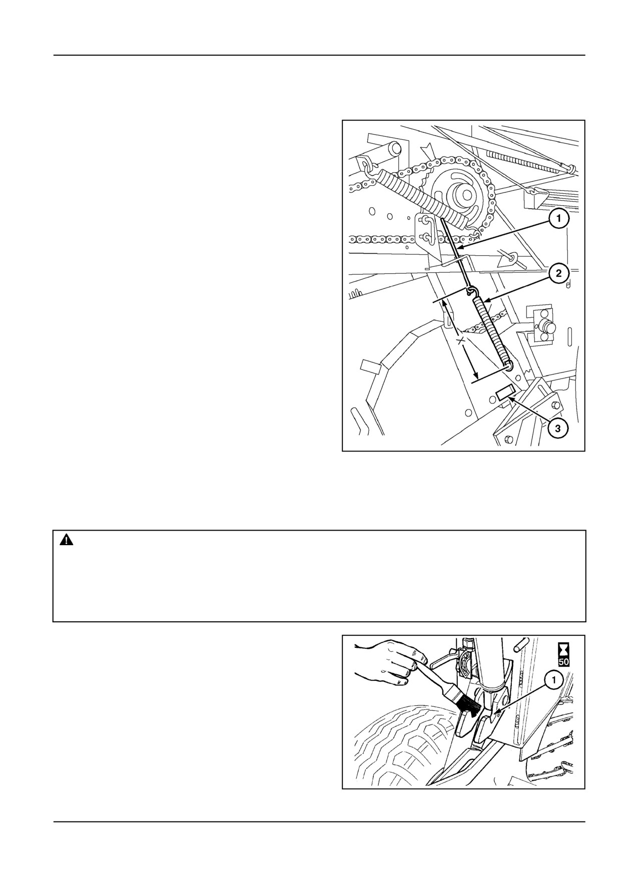
Flotation springs
Two flotation springs (2) left and right of the pickup carry
most of the pickup weight, without making it bounce ex-
cessively on rough terrain.
Adjust the springs to a length (eye to eye) of:
X = 292 - 298 mm (11.5 - 11.7 in)
Check that the stop (3) touches the chassis and that the
pickup teeth pass at 15 mm from the ground, then get the
value X through the threaded rods (1).
ZIL10FCRB011BAA
1
Tailgate [25808090]
Tailgate latching hooks
DANGER
Crush hazard! The tailgate may close faster than you can move away.
ALWAYS make sure the tailgate lockout valves are in the OFF (locked) position before working under
a raised tailgate. In the event of a sudden loss of hydraulic pressure, the tailgate will fall if the lockout
valves are not engaged. Stand clear of the tailgate before disengaging the lockout valves.
Failure to comply will result in death or serious injury.
D0002A
Clean and slightly grease the tailgate latching hooks (1)
every 50 hours of use and after storage.
ZIL10FCRB812AAA
1
7 - 37
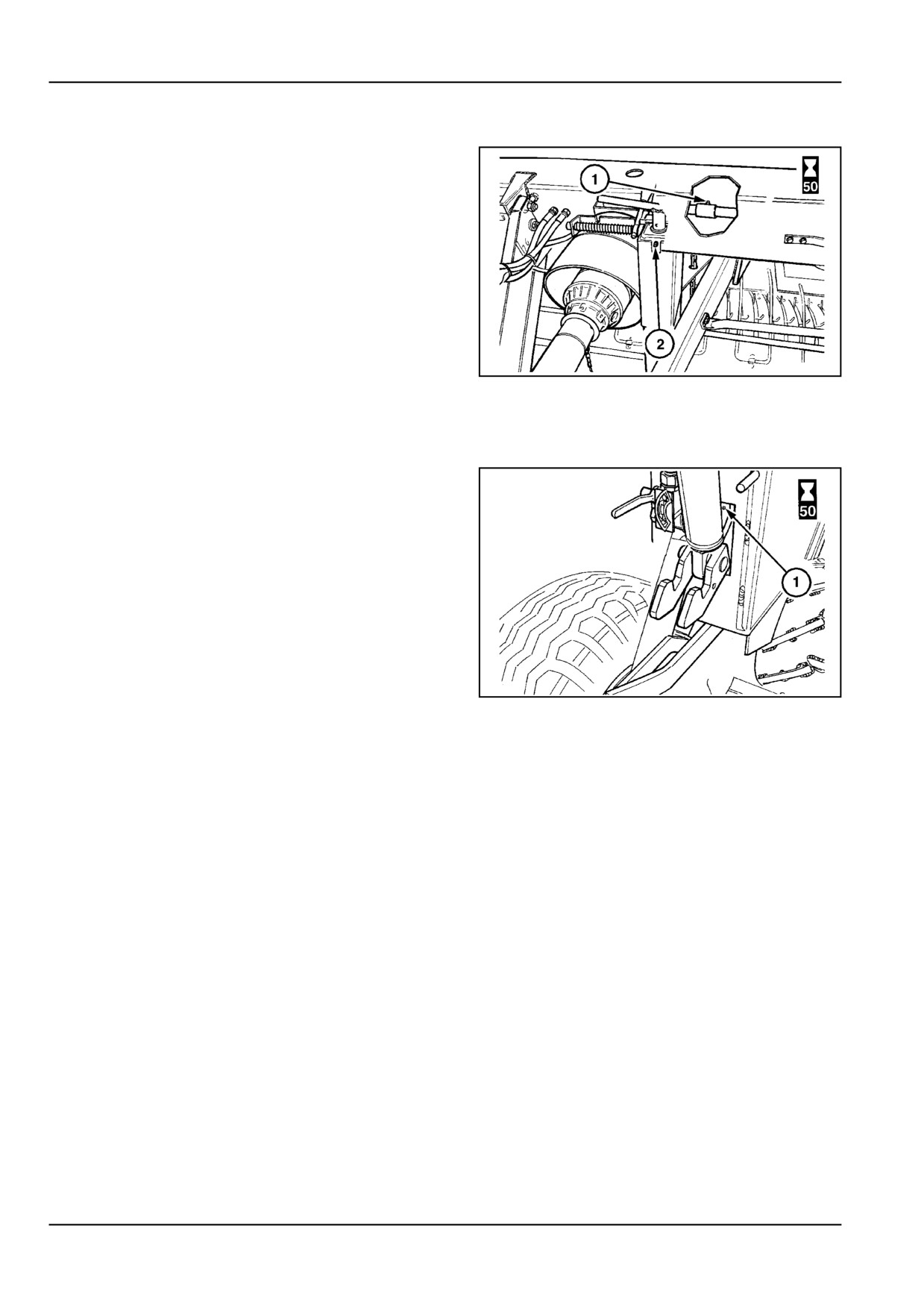
7 - MAINTENANCE
Gearbox [25808740]
Jack and gearbox output shaft
ZIL10FCRB830AAA
1
Tailgate [25809216]
Right or left hook for tailgate
ZIL10FCRB723AAA
1
7 - 38
7 - MAINTENANCE
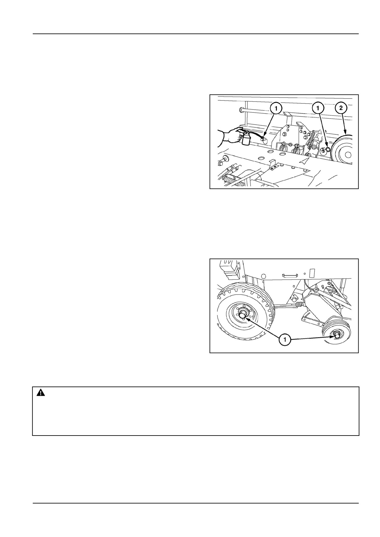
100 hours Service
Twine Wrapper [25808310]
Twine wrapper
Oil the twine wrapper chain after 100 hours of use and after
storage.
Open both spring-loaded covers and oil the chain through
the holes (1) while turning the pattern pulley (2) manually.
ZIL10FCRB772AAA
1
1200 hours or 12 months Service
Wheels and tires [25807608]
Wheel bearings
Disassemble, clean and repack the wheel bearings and
pickup gauge wheel bearings (1) with grease.
NOTE: Pickup gauge wheels are an accessory for standard
pickup models.
ZIL10FCRB769AAA
1
Hydraulic hoses Hose replacement [31336074]
WARNING
Pressurized fluid can penetrate the skin and cause severe injuries.
Keep hands and body away from any pressurized leak. DO NOT use your hand to check for leaks. Use
a piece of cardboard or paper. If fluid penetrates the skin, seek medical attention immediately.
Failure to comply could result in death or serious injury.
W0158A
7 - 39
7 - MAINTENANCE
1.
Hydraulic hoses are an important safety element in
modern machinery. However hose characteristics
under pressure, thermal heat and UV light over the
years deteriorate.
Therefore hoses are now identified with a date
printed on the hose or a band which enables age
identification.
Legislation in certain countries and good practices
require that the hydraulic hoses are replaced when 6
years old.
7 - 40
7 - MAINTENANCE
STORAGE
End of Season Parts Replacement [25869278]
Before preparing the baler for storage, check the baler for any parts that may be worn or damage and in need of
replacement. Order the parts now and replace them before the next baling season.
Always be sure to give your dealer the model and PIN of your baler. The PIN plate is located on the right side, just to
the rear and below the large side shield.
Insist on genuine replacement parts. For best performance have your baler serviced by an authorized dealer.
1.
Check the twine and net knives.
2.
Examine all of the chains and sprockets for wear.
Replace worn sprockets when installing new chains.
Always install new chain when replacing sprockets.
3.
Inspect the hitch for excessive wear.
4.
Order all of the bearings that were found to require
replacement during the storage procedure.
5.
Check all bushings for wear.
6.
Examine the wrapper systems and check for loose-
ness or excessive wear.
7.
Note any broken or bent pickup tines or severely
damaged guards.
8.
Make sure the pickup cam bearings are in good con-
dition.
9.
Check the tailgate lights.
10. Is the supply of shearbolts adequate.
Preparing for Storage [11227607]
Perform the following steps when the baler will not be used for an extended period of time.
1.
Cut the twine near the twine balls and remove all
the balls from the twine boxes. Leave the twine end
threaded in place. Move the twine balls to an inside
location to reduce moisture absorption.
2.
Remove the operators manual and store it in a safe
location.
3.
Clean the unit thoroughly
4.
Remove any material buildup on the belt rolls, wrap-
per area and in the twine boxes.
5.
Remove any twine that has wrapped on the pickup
tines
6.
Lubricate the entire baler as recommended in the
lubrication section. Apply lubricant to the threads of
the adjustment bolts and to all the hinges.
7.
Lubricate all the chains with oil and operate the baler
a few minutes to let the oil work into the chains. Care-
fully check all the bearings for any heat that would
indicate a failed bearing.
7 - 41
7 - MAINTENANCE
8.
Coat the exposed bare metal areas with a light coat
of oil. Particularly the inside of the bale chamber side
sheets.
9.
Clean the belts of oil and grease. Store the baler with
the belts at normal tension.
10. Store the unit in a dry sheltered area, if possible. If
not, cover the top with a tarpaulin or plastic.
Removing from storage [11229773]
1.
Make all the repairs that were required from the end
of the season inspection.
2.
Review the initial baler attachment and setup instruc-
tions.
3.
Check all of the wires and wire harnesses for dam-
age.
4.
Check the hydraulic lines for any signs of leaks.
5.
Install the net or twine.
6.
Check for proper flotation.
7.
Check the tires air pressure.
8.
Check proper chain tensions and alignment.
9.
Burnish all of the slip clutches.
10.
Check the twine tube travel and timing with the knife.
11.
If the baler will be used with a different tractor, check
the hydraulic fluid compatibility
12.
Check the tailgate hydraulic lock valve. Raise the
tailgate and place the valve in the locked position.
Try to move the tailgate with the tractor hydraulics.
13.
Check the hydraulic pressure setting.
14.
Check that all of the indicators operate properly.
15.
Operate the baler and check that the belts track prop-
erly.
7 - 42

7 - MAINTENANCE
TROUBLESHOOTING
Round baler [25871691]
PTO drive area
Concern
Possible Cause
Correction
Main drive shearbolt failure.
Foreign object or plugging.
Remove foreign object or plugging.
Bale too dense.
Check bale density and reduce, if
necessary.
Windrows too large.
Reduce feed rate by driving slower.
Feed rate too high.
Replace clutch.
Shearbolt fatigue.
Replace shearbolt.
Pickup area
Concern
Possible Cause
Correction
Pickup plugging.
Feeding large windrows too rapidly.
Reduce ground speed to allow the
Lumpy windrows.
pickup to tear the bunches apart as they
are fed into the machine.
Incorrect windrow preparation and/or
Optimize windrow preparation and/or
driving technique.
driving technique.
Incorrect windguard baffle plate
Properly adjust windguard baffle plate.
adjustment.
Pickup shearbolt failure.
Blockage in front of the augers caused
Reduce ground speed to allow the
by big lumps.
pickup to tear the bunches apart as they
are fed into the machine.
Optimize windrow preparation and
driving technique.
Foreign objects entering the pickup
In stony fields, raise the pickup higher
(branches, stones).
off the ground to prevent stones from
entering the pickup.
Pickup hitting the ground in rough fields.
Raise the pickup and drive around pot
holes in the field. Adjust pickup flotation
lighter (less force needed to lift the
pickup).
Shearbolt fatigue.
Install new shearbolt.
Pickup does not drop freely.
Pickup pivots binding.
Grease pickup pivots.
Pickup tines breaking.
Pickup tines digging in the ground.
Increase pickup tines to ground
Pickup set too low.
clearance.
Foreign objects or previously broken
Remove foreign objects and replace
tines in the pickup.
broken tines.
Heavy stalky conditions.
In stalky conditions, frequent pickup
tines breaking may be expected.
Crop plugging in front of the
Excessive weaving, feeding too much
Improve weaving technique, do not feed
centering augers.
crop in front of the augers.
the entire windrow to the augers.
Auger scrapers maladjusted.
Readjust auger scrapers.
Crossing windrows.
Raise the pickup when crossing
windrows.
Does not pick up material
Missing or broken pickup tines.
Replace broken or missing tines.
cleanly.
Flotation too light.
Adjust pickup flotation.
Driving too fast.
Reduce ground speed.
Pickup-to-ground clearance too high.
Reduce pickup-to-ground clearance.
7 - 43

7 - MAINTENANCE
Bale formation
Concern
Possible Cause
Correction
Feeding problems in short,
Brittle crop breaks easily when fed into
Reduce PTO speed down to 350 - 450
brittle crop conditions.
the baler.
RPM.
Disengage the PTO when running idle
on the headlands.
Bale density
Concern
Possible Cause
Correction
Bales too light and soft.
Ground speed too high.
Reduce ground speed to allow
compaction of the incoming crop. Drive
slower at the end of bale formation.
Improper windrow preparation.
Improve windrow preparation.
Full bale density setting too low.
Increase full bale density.
Bales too heavy and dense.
Crop moisture content too high.
Allow crop to dry before baling.
Ground speed too low.
Increase ground speed to leave less
compaction time to the incoming crop.
Windrow too small.
Increase ground speed or rake two
windrows together.
Full bale density setting too high.
Decrease full bale density setting.
7 - 44