New Holland BR6080. OPERATOR’S MANUAL (2011) - page 3
4 - OPERATING INSTRUCTIONS
Electrical connections [25763747]
Road lights
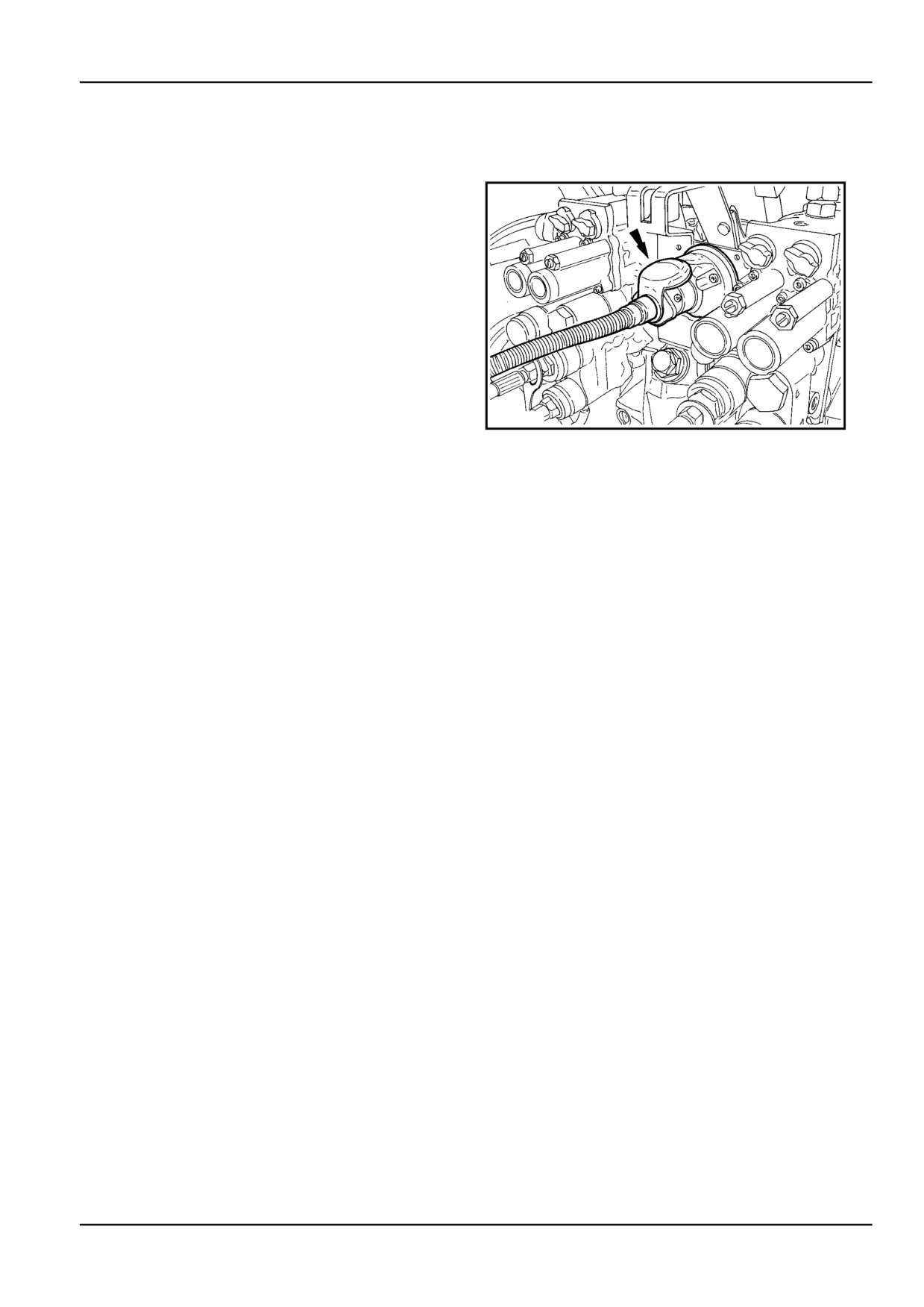
To connect the road light installation of your baler to the
tractor, fit the baler plug in the tractor socket.
The road light equipment includes front and rear parking
lights, stop lights, direction indicator lights and reflectors.
1.
Verify the proper operation of the electrical equip-
ment.
2.
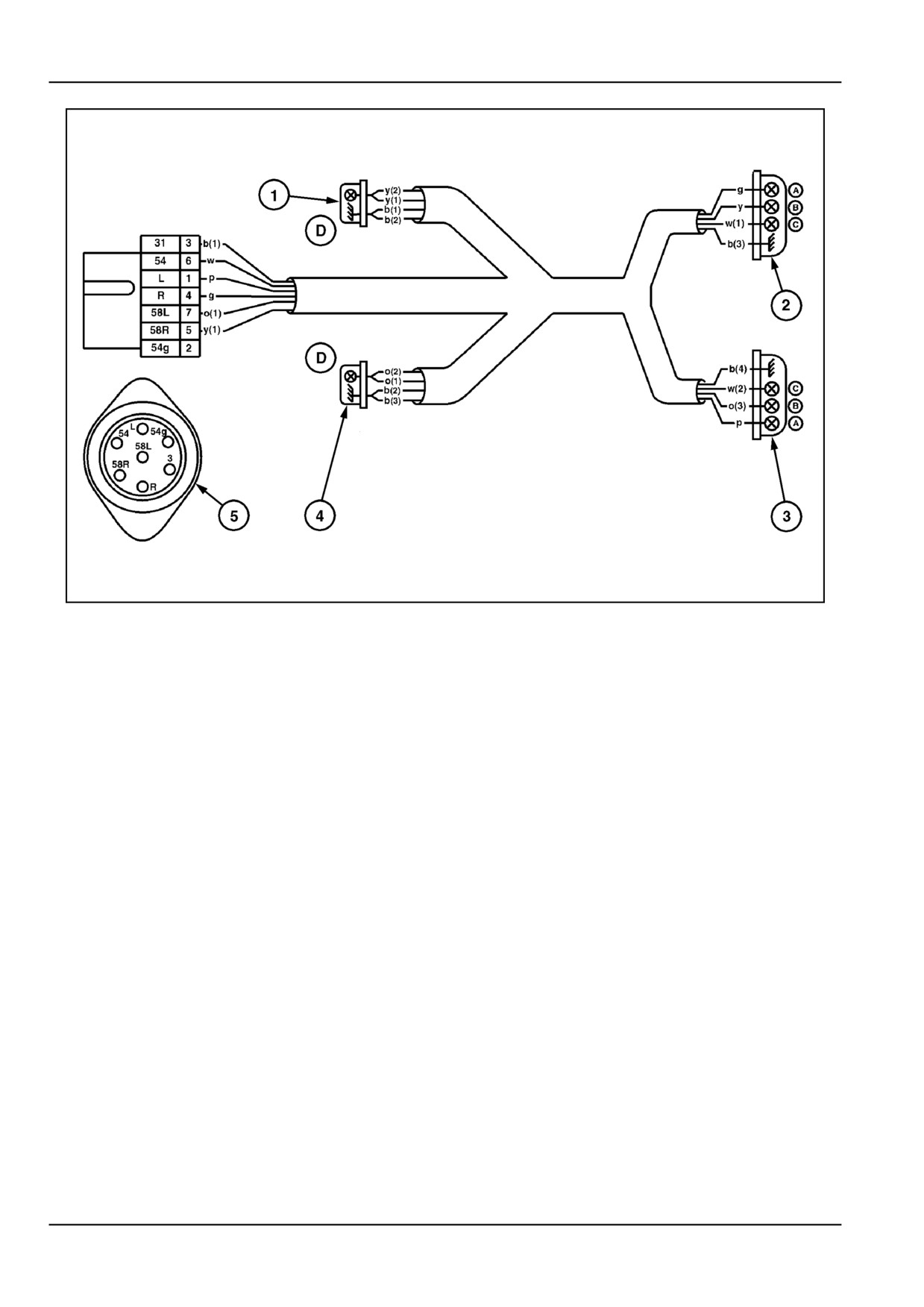
Refer to the wiring diagram if the light equipment
causes problems, verify the compatibility of the trac-
tor's and baler's electrical circuit.
ZIL10FCRB669AAA
1
4 - 19
4 - OPERATING INSTRUCTIONS
ZIL10FCRB034FAA
2
Components
Color code
1. Right front parking light
b: Black
2. Rear lights, right
w: White
3. Rear lights, left
p: Purple
4. Left front parking light
g: Green
1
: Tractor connecting plug
o: Orange
31
: Earth
y : Yellow
54
: Stop lights
L
: Direction indicator, left
R
: Direction indicator, right
58L
: Parking lights, left
58R
: Parking lights, right
54g
: -
Light bulbs
A. Direction indicator light (P - 12 V - 21 W)
B. Parking light, rear (R - 12 V - 10 W)
C. Stop light (P - 12 V - 21 W)
D. Parking light, front (K - 12 V - 10 W - DIN 72601)
4 - 20
4 - OPERATING INSTRUCTIONS
STARTING THE UNIT
Machine preparation [32296915]
With the baler hitched to the tractor and all electrical and
hydraulic connections made, prepare as follows.
Before starting the towing unit
Check all road lights and indicators are operational
1.
Ensure PTO engagement is OFF
if towing on the highway.
Start the towing vehicle and at fast idle
PTO Engagement
2.
Check the hydraulic operation of the pick up (where
3.
Set the throttle at half speed and engage the PTO,
fitted)
this lower starting speed will reduce the shock load
to the driveline.
The tailgate raise and lower
If all functions are okay the baler is now ready for its
purpose, disengage the PTO and tow or transport
The rotor reverser (where fitted)
the baler to the field:
Transport Operations.
Check electrical operation of the monitor
When at the field and before operating the baler:
Working Operations.
control box (where fitted)
PARKING THE UNIT
Parking the machine [31337534]
1.
Chock the wheels and or apply park brake (where
4.
Remove the hydraulic lines from the tractor, and
applicable)
place dust caps on the ends of the hydraulic lines.
2.
Place the jack, in the down position, and insert the
5.
Disconnect the cable for the wrapper and the tail-
pin. Turn the crank to remove the weight from the
light connector, from the tractor to the baler. Install
drawbar.
the dust caps, on the monitor harness.
3.
Remove the PTO, from the tractor and store it on
6.
Store the ends of the hydraulic hoses and wire har-
top of the A frame.
nesses in the A frame.
4 - 21
4 - OPERATING INSTRUCTIONS
4 - 22
5 - TRANSPORT OPERATIONS
5 - TRANSPORT OPERATIONS
ROAD TRANSPORT
Towing the machine [25782288]
Recommended Practice for Towing Agricul-
tural Machines
NOTE: Always investigate and comply with local road
regulations governing transporting, towing, equipment on
public roads.
Make sure a safety chain is installed (where applicable),
the pickup is in the raised position and all hoses and wire
harnesses are secured before towing the baler.
Do not carry a bale in the chamber when travelling on the
road.
Round Baler Maximum Permissible Towing Speeds On or
Off Road, but is subject to your local legislation:
With Brakes
40 km/h (25 mph) or local
regulation, whichever is
less.
Without Brakes
32 km/h (20 mph) or local
regulation, whichever is
less.
Tow agriculture equipment with proper size and weight
tractor.
Baler WITHOUT BRAKES the maximum allowed baler
weight must be below the maximum allowed towed weight
WITHOUT BRAKES found in the tractor documentation or
on the tractor PIN plate.
OR
Weight of the baler WITHOUT BRAKES must not be more
than 1.5 times the tractor weight, whichever is less.
Baler WITH BRAKES the maximum allowed baler weight
must be below the maximum allowed towed weight WITH
BRAKES found in the tractor documentation or on the
tractor PIN plate.
OR
Weight of the baler WITH BRAKES must not be more than
4.5 times the tractor weight, whichever is less.
Towing
Do not tow the baler with a bale in the bale chamber.
Make sure the reflective decals, reflective tape, reflectors
and lights are clean and clearly visible.
Lift the pickup all the way up and lock it .
Make sure the hitch pin is of adequate size and cannot
come out.
Attach the tow chain (if so equipped).
Secure all of the hydraulic lines and electrical harnesses.
If the PTO drive shaft is not attached to the towing vehicle,
use a secure strap to hold the PTO drive shaft on the A
frame.
If the baler has brakes, attach the brake lines.
5
-
1
5 - TRANSPORT OPERATIONS
Attach a safety breakaway chain/cable to the back of the
tow vehicle (where applicable).
5 - 2
5 - TRANSPORT OPERATIONS
PREPARING FOR ROAD TRANSPORT
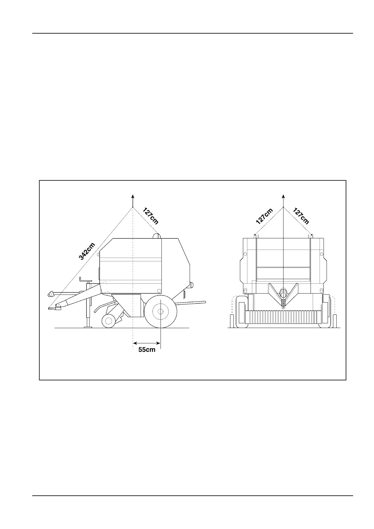
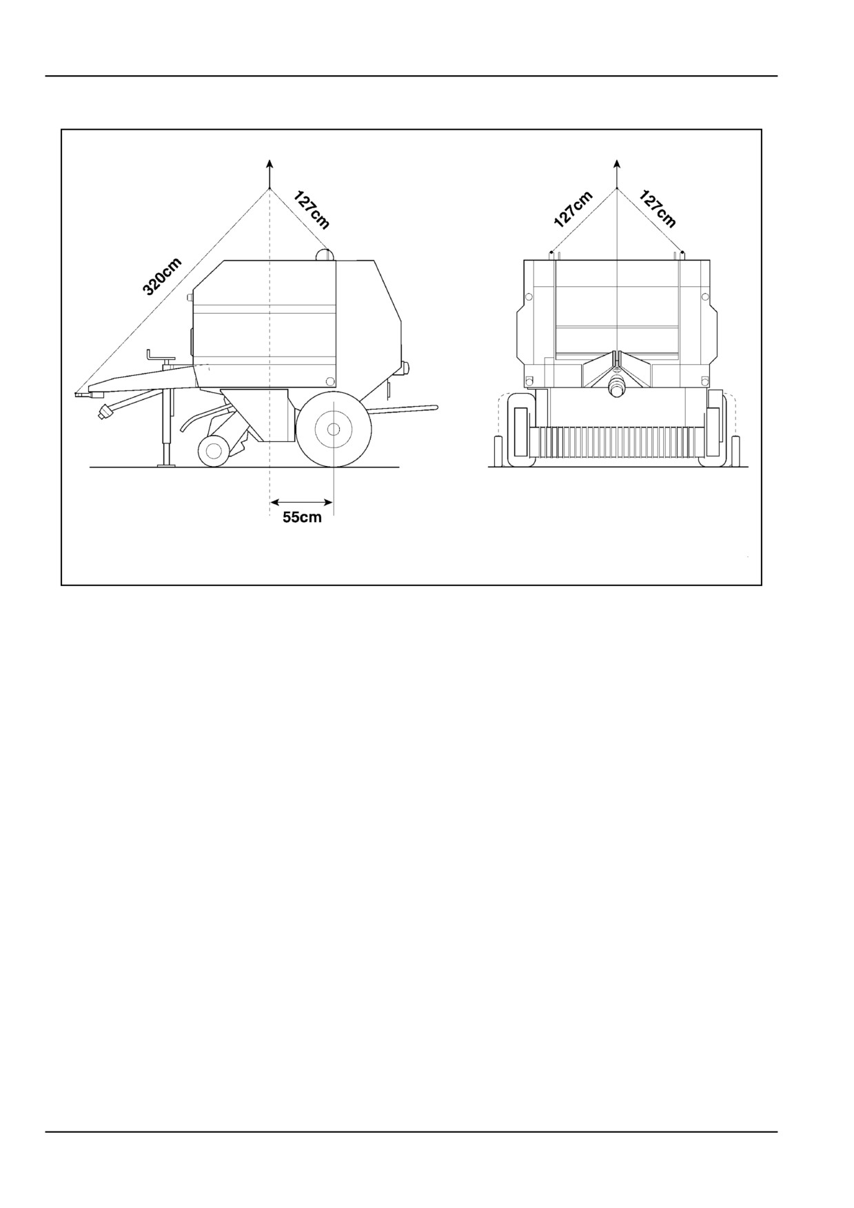
Lifting the machine [25871025]
When lifting the baler, always make sure that all loose
•
Pickup wheels
components are securely fastened to the machine:
•
Tractor wire harness and battery cable
•
PTO front half
•
Operator's manual
•
Spare net roll basket
Close all guards and lock the pickup in the transport po-
•
Hydraulic hoses
sition.
•
Monitor and road light wire harnesses
Use chains of adapted strength regarding the baler weight
•
Twine balls
of 2600 - 2700 kg (empty).
•
Net rolls
Low hitch
ZIL10FCRB003FAA
1
5 - 3
5 - TRANSPORT OPERATIONS
High hitch
ZIL10FCRB004FAA
2
5 - 4
6 - WORKING OPERATIONS
6 - WORKING OPERATIONS
GENERAL INFORMATION
Bale Formation Overview [25786363]
Bale makeup
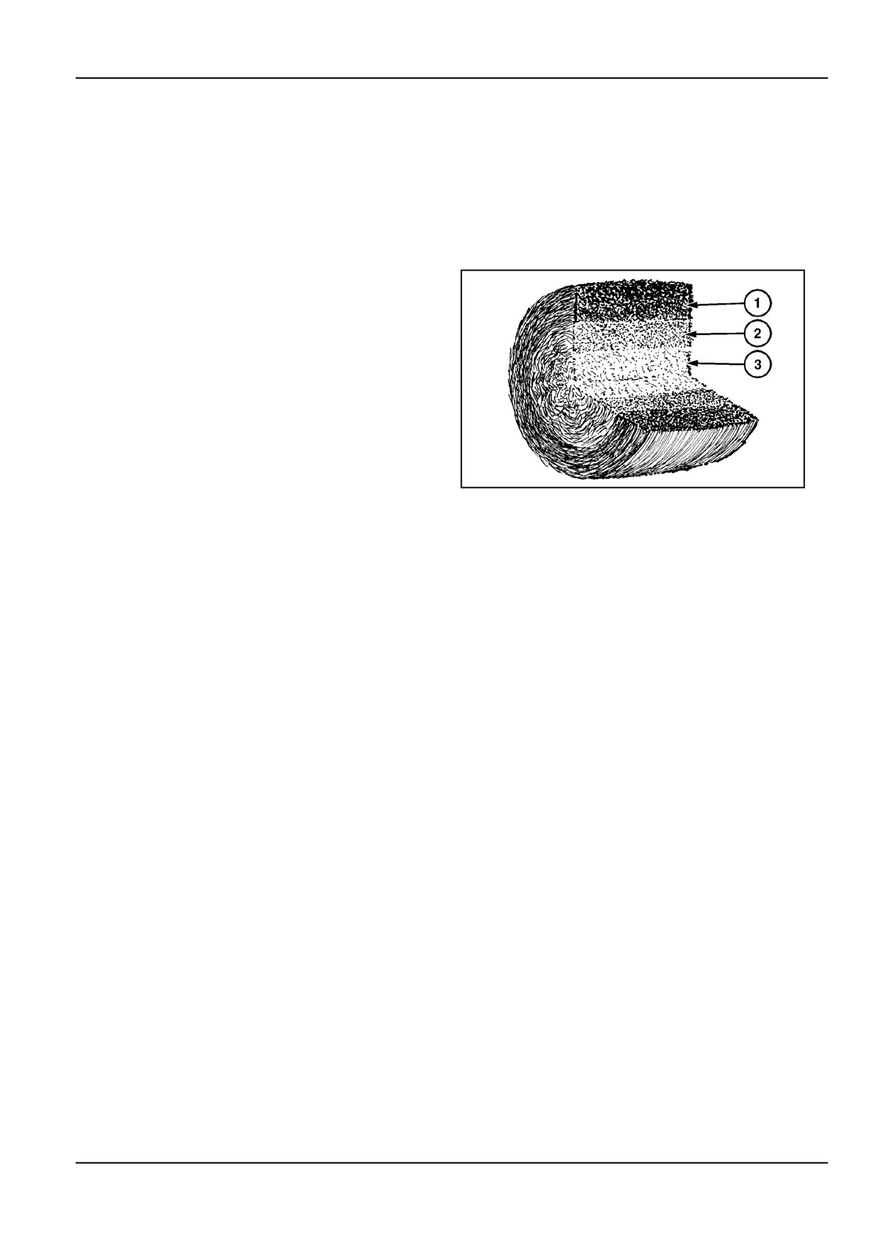
The baler is designed to make cylindrically shaped bales
not exceeding 800 kg (1763.7 lb) composed of 3 distinct
layers of varying density.
Level 1, the outer crop layer, is the most dense, providing
good weathering characteristics to the bale.
Level 2 consists of higher density layers, without damage
to the crop.
Level 3 is a low density core, allowing the crop to breath.
The thickness of these layers compared to each other will
be altered by changing the overall full bale density.
ZIL10FCRB001AAA
1
The quality of the bale is wholly dependent upon many
variables, including the type and variety of crop, how the
crop was prepared, size and shape of the windrow, mois-
ture content, feeding rate and the operator driving tech-
nique, and selected bale density.
NOTE: The thickness of these layers compared to each
other will be altered also by changing the overall full bale
density on the monitor in the tractor.
General
This allows the operator to weave and properly position
the material in
the baler, producing compact,
uniform
1.
Always work in safe conditions, on flat, hard, dry
bales.
ground.
Moisture content requirements for the round bale tech-
2.
Never stand on guards, neither in open, nor in
nique is up to 18 % maximum.
closed position.
3.
Never put hands or fingers through any holes or
•
If the moisture content is too high, spoilage can be
slots in the guarding or the chassis.
expected.
4.
Do not climb on the baler. If certain areas cannot
•
If the moisture content is too low, excessive leaf loss
be reached from the ground, use a stable step or
and shatter will occur.
ladder to reach these areas.
Cut the crop as long as possible. In most crops, longer
5.
Thoroughly read and understand this manual, in
material is easier to bale and results in smoother finished,
particular the safety instructions, before proceeding
more weather-resistant bales.
with operation, adjustments and maintenance, and
repairs described in this manual.
Do not over condition the material, particularly
legume-type crops such as lucerne and clover.
Preparing the hay crop for baling
Over conditioning will cause the leaves to dry too quickly
The crop to be baled can be prepared in a number of
and break off where they are damaged, resulting in
ways, depending on your preference and equipment
losses. If the bales are to be stored outside, excessive
available. The most desirable bales are produced when
shattering of stems will invite moisture absorption.
the crop is cut, conditioned and then raked into windrows
of the proper size.
Under conditioning can also cause spoilage, particularly
when baling cane-type crops and other heavy stemmed
materials.
6
-
1
6 - WORKING OPERATIONS
Excessively dry, slippery materials sometimes encoun-
Raking two windrows together under these conditions will
tered in maize stalks, certain grass types, and various
also help baling efficiency and performance. Select a
types of grain straw can be successfully baled providing
lower full bale density.
the material is of sufficient length to hold the bale together.
Stalk-type crops
Wilted grass for silage
In baling long stalk crops such as sorghum or maize
The crop can be cut and prepared with the usual equip-
stalks, especially when the crop is extremely dry (less
ment such as a mower or a mower-conditioner and a ted-
than 10 % moisture content) or has been shredded with a
der rake.
rotary type cutter, baling difficulties may be experienced.
Produce uniform swaths. An even, full windrow is desir-
Under these conditions, the material is crushed easily and
able. The best results for conservation are obtained when
loses its form and shape. The bale will have tendency to
the crop is baled at a dry matter content between 40 - 60
disintegrate or not start rolling at all.
%.
Slowing the PTO speed down to 350 - 450 RPM while
maintaining a normal feed rate will usually allow the baling
Straw crops
operation to take place.
If at all possible, ensure at the time of combining a grain
Other adjustments that will help are:
crop that the straw is not chopped excessively by the com-
bine's threshing mechanism. Do not stir up the swath
•
Decrease the full bale density.
prior to baling if the straw is already very dry and short.
A properly sized, full swath produced by a large combine
•
Disengage the PTO when not feeding material,
will give better results than a very small swath. The width
such as in field corners and when turning on the
of the swath, as described below, can be controlled by
headlands or at the end of windrows.
adding deflectors in the combine straw hood.
Short or brittle crops
Important operating tips Straw / grass type
Baling difficulties may be experienced when baling short,
crops
stalky crops (hay or straw), especially when the crop is
extremely dry (less than 10 % moisture content) or has
In voluminous straw windrows, make sure that the crop
been shredded with a rotary type mower or chopper.
is not rolling under the tractor rear axle and baler hitch.
When breaking loose, this may plug the baler pickup and
Under these conditions, the material is crushed easily and
throat.
loses its normal form and shape. The bale will have ten-
dency to disintegrate or will not start rolling at all.
In these conditions, try to pickup the windrows in the same
direction as they were laid down by the combine in order
Slowing the PTO speed down to 350 - 450 RPM while
to obtain a more even feed of the crop. When baling straw
maintaining normal feed rate will usually allow the baling
windrows in the same direction as they were laid down by
operation to take place. Sometimes it may only be nec-
the combine, they will have a shiny aspect. Looking in
essary to slow down until the core is formed.
the opposite direction, the windrows will have a more dull
appearance.
Other adjustments that will help are:
Fit a canvas underneath the tractor body and rearward
•
Decrease the full bale density.
under the hitch to deflect the crop down.
•
Disengage the PTO when not feeding material,
Adjust the windguard baffle plate high enough to prevent
such as in field corners and when turning on the
it from bulldozing the windrow.
headlands or at the end of windrows.
In heavy, bunchy, uneven windrows, reduce the ground
Bale density
speed when necessary to allow the pickup to tear the
bunches apart as they are fed into the machine. This will
Bale density is determined by many variables including
minimize plugging of the pickup and the feeder area.
type and condition of the crop, method of preparing the
crop, moisture content, size and shape of the windrow
Light windrowed crops
and travel speed. Bale density can be controlled by in-
creasing or decreasing the volume of the windrow and by
In very small windrows, the incoming crop is crushed by
altering the ground speed.
the weight of the bale. As a result, pressure buildup is
much slower which may result in too dense bales.
Mechanical bale density adjustment can be controlled
from the tractor seat by altering the bale density at which
If problems are experienced with feeding small windrows,
the wrap cycle is initiated.
increase the ground speed or decrease the PTO speed.
6
- 2
6 - WORKING OPERATIONS
Experience has shown that the best quality bales (with
For well shaped and dense bales, reduce the forward
regard to making, handling, storing and feeding) result if
speed near completion of bale formation.
the operator keeps the following points in mind.
This will allow some relaxation time for the incoming crop
to be well compressed, resulting in a tight, waterproof
Full bale density
outer layer with good conservation characteristics.
Full bale density is determined by the amount of tailgate
opening during bale formation and is controlled from the
Windrow size
tractor seat by altering the bale density at which the wrap
cycle is initiated.
Refer to "Windrow size - Feeding the windrow - Bale for-
mation".
Depending on crop conditions, recommended full bale
density settings are:
Systematic procedure when starting to bale
•
1 maximum at first start-off.
The procedure below outlines the steps to be taken when
starting off in a new field.
•
1 for hay crops, to allow aeration and breathing of
the bale core during conservation.
Special attention will be paid to precautions to be taken
•
1.5 to 2 for straw and silage crops, to ensure maxi-
when making the first bales at initial start-off.
mum density of the bales.
1.
Check if the baler is properly loaded with twine Re-
•
Very high densities can be achieved with higher set-
fer to "Loading twine".
tings, but this will result in higher power needs and
maintenance costs, as well as increased shearbolt
2.
Select the desired number of wraps on the pattern
failures.
pulley. Refer to "Loading twine". Make sure the
twine wrapper is in the home position.
ATTENTION: Some crops (e.g. wet silage) can result in
bales exceeding the maximum weight limit of 800 kg. It
3.
Lower the pickup and check for correct pickup
is then extremely important to reduce full bale density to
height suitable for the field to be baled.
keep weight within this limitation.
NOTE: On machines fitted with the pickup hydraulic
Continuously making overweight bales may appreciably
lift feature (optional), lower the pickup hydraulically
reduce baler life.
and place the valve lever in the float position.
At initial start-off with a new baler, select a lower full bale
density for the first bales until the paint inside the bale
4.
Set the full bale density pointers. Set the full bale
chamber has become polished.
density alarm (optional).
5.
Make sure the tailgate is closed and latched. The
The density springs in the tailgate are preloaded in the
tailgate hooks must be pulled up and engaged in
factory. This preload cannot be changed in the field.
the density spring pins, the density indicators point
at "zero" density.
Feed rate
6.
Engage the PTO Less shock is transmitted to the
The amount of time the material spends in the bale cham-
driveline if the tractor is set at low idle speed before
ber has an important effect on bale density. If large volu-
engagement. After the baler is running, adjust the
minous windrows are fed into the baler quickly, the den-
PTO speed up to 540 RPM.
sity of the ejected bales will be lower than if a lower rate
7.
Start baling. Closely watch the pickup performance
of feed is used.
and the left and right bale density indicators during
bale formation.
A longer cycle time will result in denser bales, but crop
loss and baling capacity will decrease. The operator
should learn to adjust the ground speed in order to pro-
vide a feed rate consistent with optimum performance.
6 - 3
6 - WORKING OPERATIONS
Windrow size - Feeding the windrow - Bale
formation
Windrow size
Good, uniform bales are made by feeding either full bale
chamber width windrows of 110 - 130 cm (43.3 - 51.2 in),
or narrow windrows of half or less the chamber width, 70
cm (27.6 in) or less. Avoid medium sized windrows of 80
- 100 cm (31.5 - 39.4 in), which are between half and full
chamber width. As the operator crosses this size windrow
to alternately feed material into the side ends of the bale,
material is continuously fed into the centre of the bale.
This will result in barrel-shaped bales. On the other hand,
oversized windrows of more than 140 cm (55.1 in) wide
will increase the risk of blockages in the pickup.
In order to avoid crop losses and ensure good bale forma-
tion, try to obtain flat, even windrows of 0.3 - 0.4 m (11.81
- 15.75 in) high. This will result in higher density, lower
power consumption and better conservation characteris-
tics, compared to high irregular windrows.
General operating tips
•
For good bale starts, reduce the forward speed at
the beginning of bale formation.
•
For well shaped and dense bales, reduce the for-
ward speed near completion of bale formation. This
will allow some relaxation time for the incoming crop
to be well compressed, resulting in a tight, water-
proof outer layer with good conservation character-
istics.
•
Prevent stones, boards or other foreign materials
from entering the baler to avoid damage to the ma-
chine components.
•
Do not backup the baler over the windrow to prevent
material from being wedged between the floor roll
and the pickup frame.
•
Avoid driving the pickup wheels over the windrow
(especially when baling on the headlands), as this
may cause blockages and wrapping around the
pickup wheels and centering augers, as well as
between the pickup side sheets and the windguard.
•
On wide pickup models, keep in mind that the pickup
centering augers only serve to take up irregularities
in the windrow. So, when feeding the sides of the
bale chamber, do not drive on the augers to avoid
blockages in this area.
6 - 4
6 - WORKING OPERATIONS
Feeding the windrow
Full bale chamber width windrows
120 - 140 cm (47.2 - 55.1 in).
Full width windrows are desirable since no weaving or
crossing the windrow is needed. The windrow should be
even and rather flat, without too much of a crown in the
middle, as this will result in barrel shaped bales.
Drive straight over the centre of the windrow to obtain
well-shaped cylindrical bales with properly filled and
dense bale ends.
Narrow windrows
60 - 70 cm (23.6 - 27.6 in).
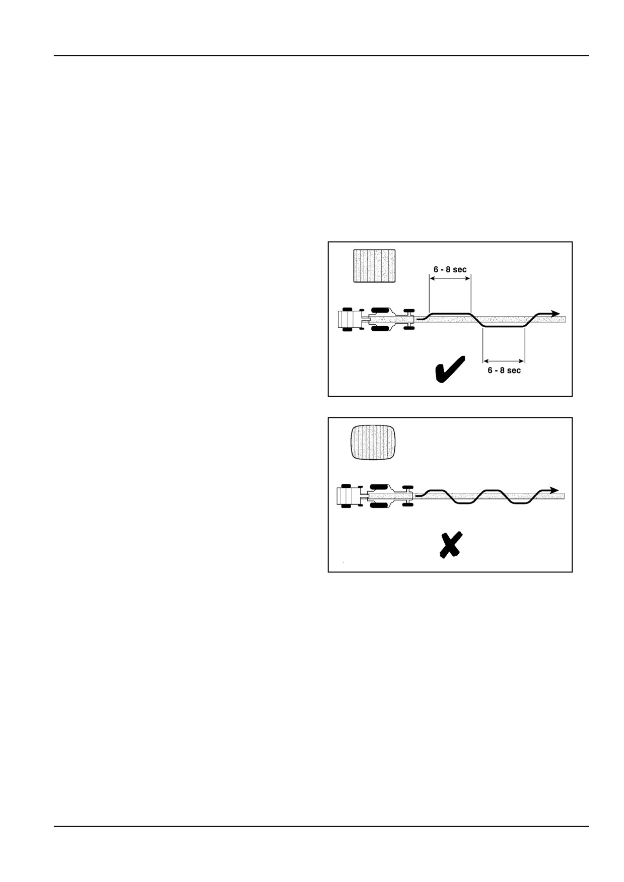
When baling narrow windrows, start bale formation in the
centre to enable rotation of the bale during its formation.
Then start feeding the left and right side of the bale cham-
ber alternately by running 6 - 8 s on one side, then cross-
ing over to the other side for another 6 - 8 s and so forth,
Figure 2. Watch the bale density indicators during bale
formation to correct the weaving pattern, if needed.
When the bale is near completion, feed the windrow in the
middle of the pickup before stopping the forward motion.
ZIL10FCRB814AAA
2
Do not weave continuously as shown in Figure 3. If the
left/right shifting is too frequent, the ejected bale will be
barrel-shaped, causing stability (twine end wraps falling
off), transport and stacking problems. Furthermore, bar-
rel-shaped bales put high loads on the middle of the con-
veyor bars and on the chain, and increased wear or even
damage may result.
Medium-sized windrows
80 - 100 cm (31.5 - 39.4 in).
Avoid medium sized windrows! When crossing these
windrows to fill the other side of the bale, material is con-
ZIL10FCRB815AAA
3
tinuously fed to the centre. At the end of bale formation,
more material will be fed in the centre of the bale resulting
in barrel-shaped bales (Figure 3), causing stability (twine
end wraps falling off), transport and stacking problems.
Furthermore, barrel-shaped bales put high loads on the
middle of the conveyor bars and on the chain rollers, and
increased wear or even damage may result.
Oversized Windrows: Wider than 140 cm (55.1 in).
Too wide a windrow may lead to blockages at the pickup
sheets, the pickup centering augers and the feeder area,
as well as to problems with bale ejection.
6 - 5
6 - WORKING OPERATIONS
Safety hints for operational problem condi-
tions
Whenever leaving the tractor seat
1.
Stop the tractor PTO shut down the engine and ap-
ply the handbrake.
2.
Verify that all rotating parts have stopped.
3.
Cut electrical power to the implement, unless other-
wise required.
4.
Do not hurry, remain alert for machine components
under pressure, tension, unbalance, heat, etc.
5.
Mind the PTO shaft, and ensure all guards are in
good condition.
6 - 6
6 - WORKING OPERATIONS
Pick up [32466429]
Standard pickup
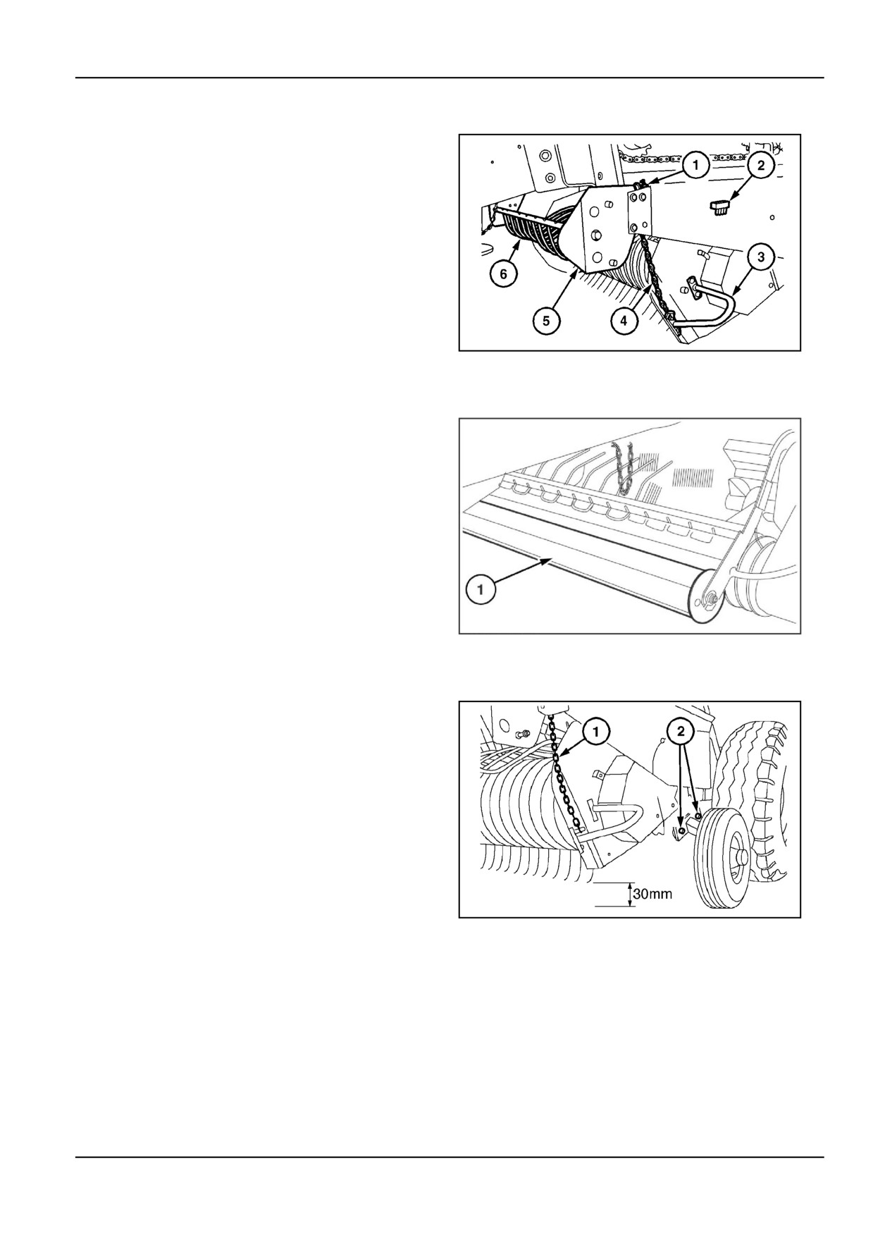
Windguard, Figure 1.
The windguard (6) is made quick-attach by means of a
spring-loaded plate (5), to make clearing of blockages
more easy.
Furthermore, the windguard can be located in 2 different
positions:
•
Lower hole for short crop, small windrows.
•
Upper hole for big voluminous windrows.
ZIL10FCRB752AAA
1
Roller windguard (where fitted)
A roller windguard is available which aids crop flow into
the rotor.
The windguard can be located in 2 different positions:
•
Lower hole for short crop, small windrows.
•
Upper hole for big voluminous windrows.
ZIL10FCRB182AAA
2
Pickup height
On machines fitted with the accessory pickup gauge
wheels, adjust the gauge wheels with bolts (2) to obtain a
minimum pickup tine to ground clearance of 30 mm (1.2
in). Increase the pickup height in stony or uneven field
conditions.
Adjust suspension chain (1) with a little slack.
In extremely rough or high stubble conditions, it is even
recommended to work with the pickup wheels off the
ground. Lift the pickup completely and adjust the pickup
height as explained below.
On machines without gauge wheels, adjust the pickup
ZIL10FCRB779AAA
3
height with chain (1). To change the pickup height, grab
the handle (3) (Figure 1) and lift the pickup manually to
relocate the chain in the notch (1), Figure 1.
On machines equipped with the pickup hydraulic lift fea-
ture, the pickup can be lifted with the tractor hydraulics to
adjust chain (1). For road transport, lift the pickup com-
pletely and engage the chain as high as possible. Then
lower the pickup hydraulically and place the valve lever in
the neutral position.
6 - 7
6 - WORKING OPERATIONS
Wide pickup
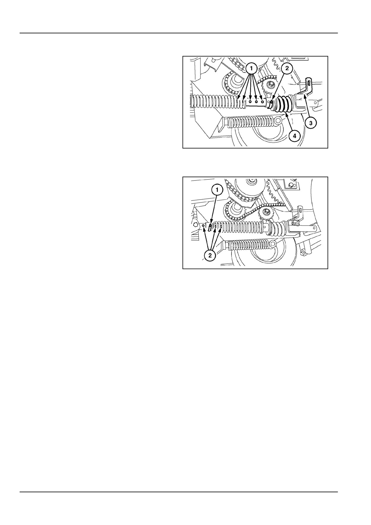
Remove the rear spring pin (2) from its transport position
hole and relocate it to support (3).
With the pickup hydraulic lift attachment, lower the pickup
and place the tractor valve lever in the float position.
The normal pickup tines to ground clearance is 30 mm
(1.2 in). Adjust the ground clearance as described for the
standard pickup.
ZIL10FCRB786AAA
4
Pickup fixed height position
For special conditions such as rough straw fields, the
pickup flotation linkage provides the possibility to work
with the gauge wheels off the ground.
To work with the gauge wheels off the ground, lift the
pickup hydraulically and locate rear spring pin (2) in one
of the holes for fixed height position (1).
Lower the pickup hydraulically. The pickup will now be
suspended by rear spring (4).
Normal pickup flotation starts when a force of 300 N (67.4
lb) is applied on the gauge wheel. If needed, lift the pickup
again and relocate the front spring pin (1) in one of the
ZIL10FCRB787AAA
5
holes (2) for pickup flotation.
6 - 8
6 - WORKING OPERATIONS
Baler Preparation [31337303]
Check that the twine tubes, net knife is in the home po-
sition, that the pickup is lowered and that the tailgate is
latched.
Set the throttle at half speed.
Turn on the PTO.
The lower starting speed will reduce the chance of shear-
ing the driveline shearbolt, on some units, and reduce
peak loads on the driveline.
Increase the throttle to the rated speed.
Do not operate at more than the rated speed, less will
save wear on the baler.
ATTENTION: Do not allow stones, boards or other foreign
material to enter the baler. Damage to the baler may re-
sult.
Do not back over windrows. Crop could become wedged
between the pickup frame and the floor roll.
Driveline protection [25789250]
NOTE: The PTO Driveline protection on this baler varies
between the pickup fitted and or optional Cut out clutch
on the wide version and considered as:
1. Wide angle with optional cut-out clutch 1300 N·m
2. Single joint PTO with shearbolt 1100 N·m
3. Wide angle PTO with shearbolt 1100 N·m
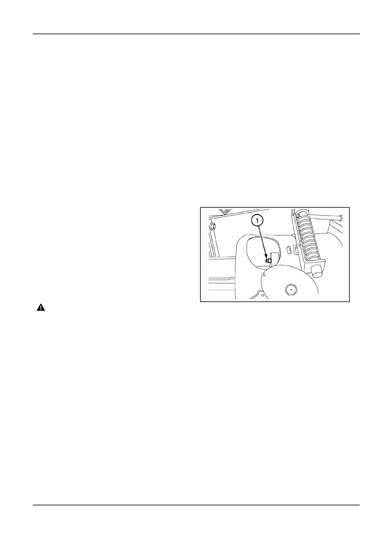
Where the baler driveline is protected from overload and
damage by a shearbolt (1) in the PTO driveline, and the
shearbolt breaks, the power transmission from the tractor
to the baler will be interrupted and the machine will start
bulldozing the crop in front of the pickup.
Then proceed as follows:
ZIL10FCRB783AAA
1
WARNING
Entanglement hazard!
Disengage the Power Take-Off (PTO), turn off
the engine, and remove the key. Wait for all
movement to stop before leaving the opera-
tor's position. Never adjust, lubricate, clean,
or unplug machine with the engine running.
Failure to comply could result in death or se-
rious injury.
W0227A
6 - 9
6 - WORKING OPERATIONS
Shearbolt failed
Look for the cause of the problem and unplug the pickup,
Stop the tractor forward motion immediately. Reverse a
if necessary.
few metres.
Replace the shearbolt through the access hole in the PTO
Disengage the PTO, shut off the tractor engine and apply
guard. Should the shearbolt be difficult to access, then
the handbrake before leaving the tractor.
remove the complete PTO shaft from the gearbox input
shaft. Securely reinstall the PTO shaft afterwards.
WARNING
Main reasons for shearbolt failures are:
Personal Protective Equipment
(PPE) re-
quired.
Big lumps entering the baler at the end of bale formation
When assembling, operating, or servicing the
machine, wear protective clothing and PPE
Too high density bale in the bale chamber
necessary for the particular procedure. Some
PPE that may be necessary includes protec-
Stones, branches or other foreign objects entering the
tive shoes, eye and/or face protection, hard
baler and blocking the conveyor bars
hat, heavy gloves, filter mask, and hearing
protection.
Shearbolt fatigue
Failure to comply could result in death or se-
rious injury.
W0353A
6 - 10

6 - WORKING OPERATIONS
PTO cut out clutch (Optional)
A two cam-type cut-out clutch in the PTO drive shaft, just
in front of the gearbox in the cross beam of the baler,
protects the driveline and the baler from overload.
The clutch is factory-set at 1300 N (292.3 lb) torque and
does not require adjustment or maintenance.
In case of overload, the clutch will automatically break
loose and stop driving the baler.
A noise will be heard, the baler will stop operating and
start bull dozing the windrow in front of the pickup.
This will mostly happen when a big lump is fed into the ma-
ZIL10FCRB055AAA
2
chine at the end of the bale formation process. Too high
setting increases the chance of overloading the clutch.
When the clutch breaks loose proceed as follows:
1.
Stop tractor forward motion immediately and re-
verse for a few metres.
2.
Shut off the tractor PTO completely this will reset the
cut-out clutch.
3.
Reduce the engine speed to somewhere just above
engine low idle speed.
4.
Reengage the tractor PTO (at low engine speed) in
a start stop manner, trying to clear the blockage.
5.
Normally the blockage will clear itself after a few
attempts. Increase the PTO speed back to 540 RPM
and continue baling.
NOTICE: In case of heavy blockages (ex stones) the
clutch may not fully reengage and continue hammering
or the tractor may shut down. Do not continue to run
the baler like this as fast wear or even damage to the
driveline may result.
WARNING
Entanglement hazard!
Disengage the Power Take-Off (PTO), turn off
the engine, and remove the key. Wait for all
movement to stop before leaving the opera-
tor's position. Never adjust, lubricate, clean,
or unplug machine with the engine running.
Failure to comply could result in death or se-
rious injury.
W0227A
In the case of severe blockage and the clutch will not reset
after a few short attempts proceed as follows:
1.
Shut off the PTO and the tractor engine
2.
Observe the problem
3.
Clear the blockage by hand (ex eject the bale, pull
out the excess to the front of the pickup etc)
4.
Continue baling
6 - 11
6 - WORKING OPERATIONS
Pickup shearbolt (standard pickup models
only)
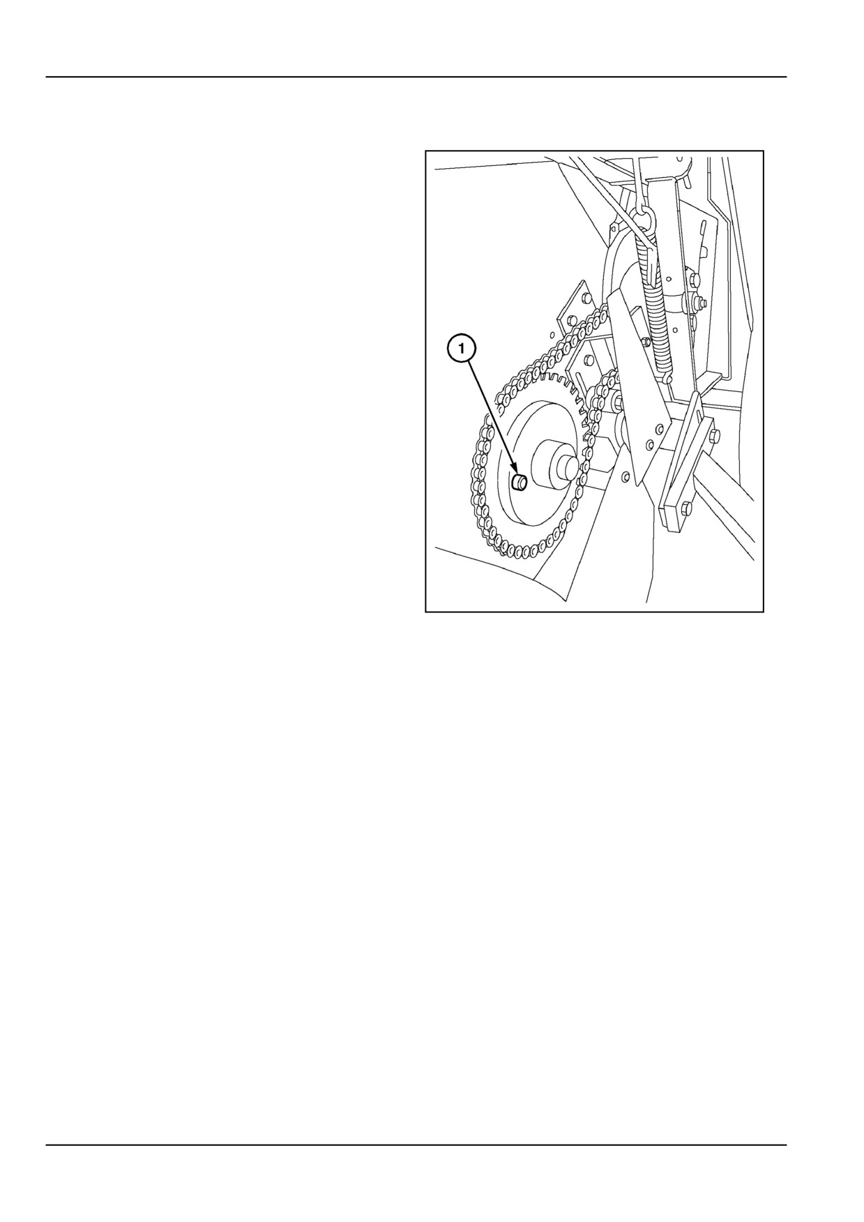
The pickup driveline is protected from damage and over-
load by a shearbolt (1) in the pickup drive sprocket.
When the pickup shearbolt breaks, the pickup reel drive is
stopped and the pickup will start bulldozing the windrow.
ZIL10FCRB016BAA
3
6 - 12

6 - WORKING OPERATIONS
Use genuine shearbolts at all times and keep spare shear-
bolts in the holder (1).
To ease the clearing of blockages, the pickup windguard
is made quick-attach.
To gain access to the shearbolt, remove the bolt at (2) and
pivot the guard (3) down. Guards removed for clarity
In case of a pickup shearbolt failure, proceed as follows:
1.
Stop the tractor forward motion immediately. Re-
verse a few metres.
2.
Disengage the PTO shut off the tractor engine and
ZIL10FCRB784AAA
4
apply the handbrake before leaving the tractor.
3.
Look for the cause of the problem and unplug the
pickup, if necessary. Pull the crop out to the front.
4.
Replace the pickup shearbolt.
Main reasons for shearbolt failures are:
•
Big lumps of silage entering the pickup
•
Unexpected pot holes in rough fields
•
Pickup tine to ground clearance too small, pickup
tines digging in the ground
•
Stones, branches or other foreign objects entering
the pickup
•
Shearbolt fatigue
6 - 13

6 - WORKING OPERATIONS
Pickup shearbolt (wide pickup models only)
The pickup driveline is protected from damage and
overload by a shearbolt (2) in the pickup drive sprocket.
Guards opened for clarity
When the pickup shearbolt breaks, the pickup reel and
auger drive is stopped and the pickup will start bulldozing
the windrow.
Use genuine shearbolts at all times and keep spare shear-
bolts in the holder (1).
To ease the clearing of blockages, both the first and sec-
ond pickup windguard are made quick-attach.
ZIL10FCRB785AAA
5
To gain access to the shearbolt, open the left-hand service
door and the pickup access door.
In case of a pickup shearbolt failure, proceed as follows:
1.
Stop the tractor forward motion immediately. Re-
verse a few meters.
2.
Disengage the PTO shut off the tractor engine and
apply the handbrake before leaving the tractor.
3.
Look for the cause of the problem and unplug the
pickup, if necessary. Pull the crop out to the front.
4.
Replace the pickup shearbolt.
Main reasons for shearbolt failures are:
•
Big lumps of silage entering the pickup and blocking
the centering augers
•
Unexpected pot holes in rough fields
•
Pickup tine to ground clearance too small, pickup
tines digging in the ground
•
Stones, branches or other foreign objects entering
the pickup
•
Shearbolt fatigue
6 - 14
6 - WORKING OPERATIONS
Feeder overload spring (wide pickup models
only)
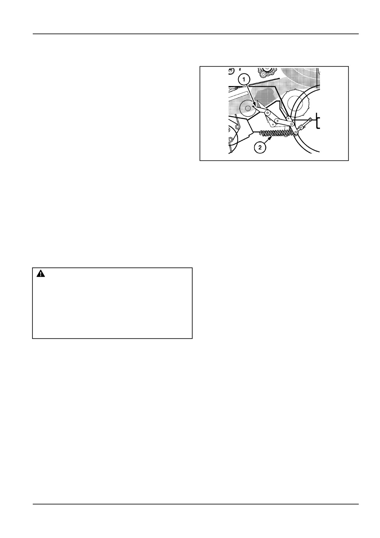
The crank-type feeder of the wide pickup models is pro-
tected from overload and damage by a double breakaway
spring (2) in the feeder drive linkage.
Should overload occur in the feeder area, the feeder tines
(1) will break away against the blockage, but the feeder
drive will not be interrupted.
1.
Stop the tractor forward motion immediately. Re-
verse a few metres.
2.
Disengage the PTO shut off the tractor engine and
apply the handbrake before leaving the tractor.
3.
Look for the cause of the problem and unplug the
ZIL10FCRB727AAA
6
pickup and feeder, if necessary. Remove the first
and second windguard. Pull the crop out to the front.
Main reasons for feeder tine breakaway are:
•
Big lumps of silage entering the feeder and blocking
the feeder tine slots between the feeder and the floor
roll
•
Foreign objects, such as stones, branches,
•
Maladjusted breakaway springs. For more details,
refer to Maintenance Section.
Cleared blockage
WARNING
Crush hazard resulting from entanglement!
After clearing a blockage, re-distribute the
crop material in a windrow. Never attempt
to feed crop material into the machine with
hands, feet, or other objects.
Failure to comply could result in death or se-
rious injury.
W0036A
6 - 15
6 - WORKING OPERATIONS
Twine Wrapper [25787078]
Loading twine
Virtually any type of twine will suit the baler:
•
Sisal twine from 250 m/kg up to 400 m/kg (the latter
for low bale weight only, not for silage).
•
Polypropylene twine from 350 m/kg up to 750 m/kg
(the latter for low bale weight only, not for silage).
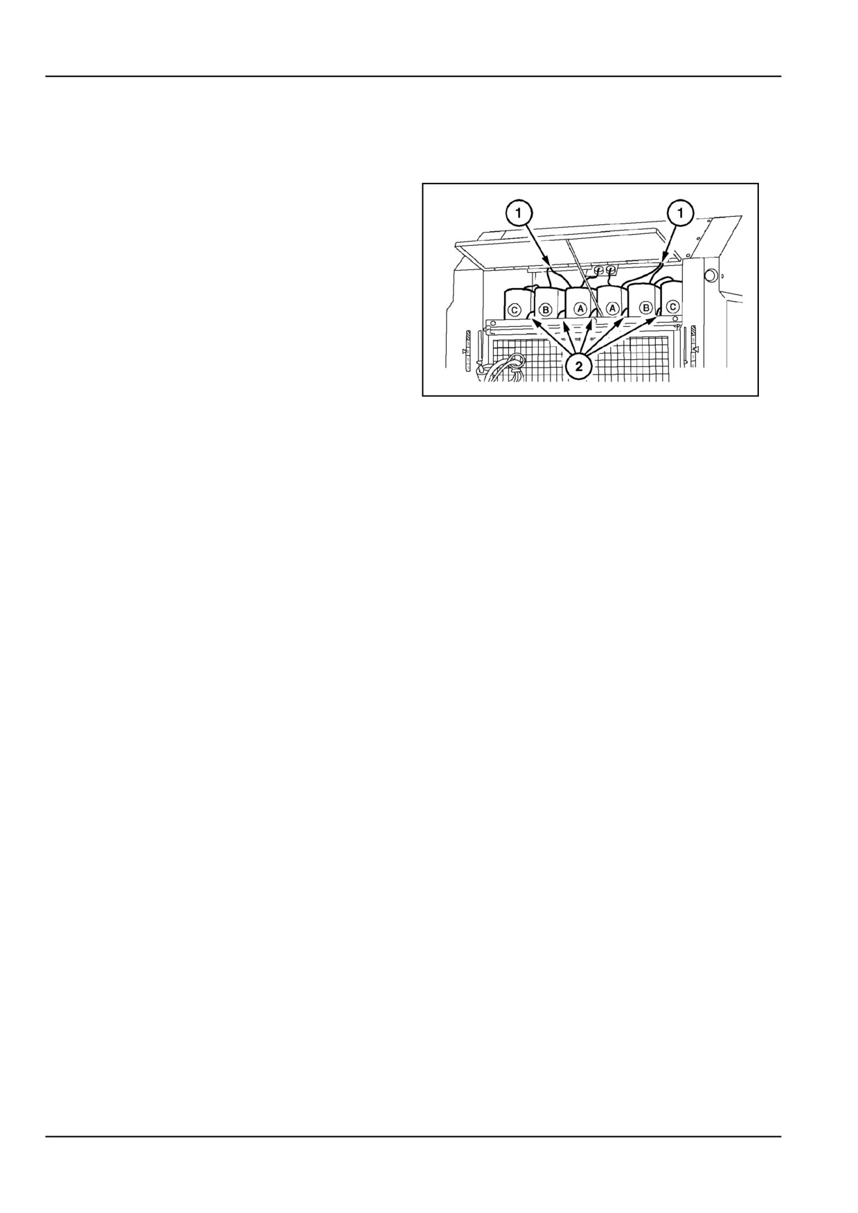
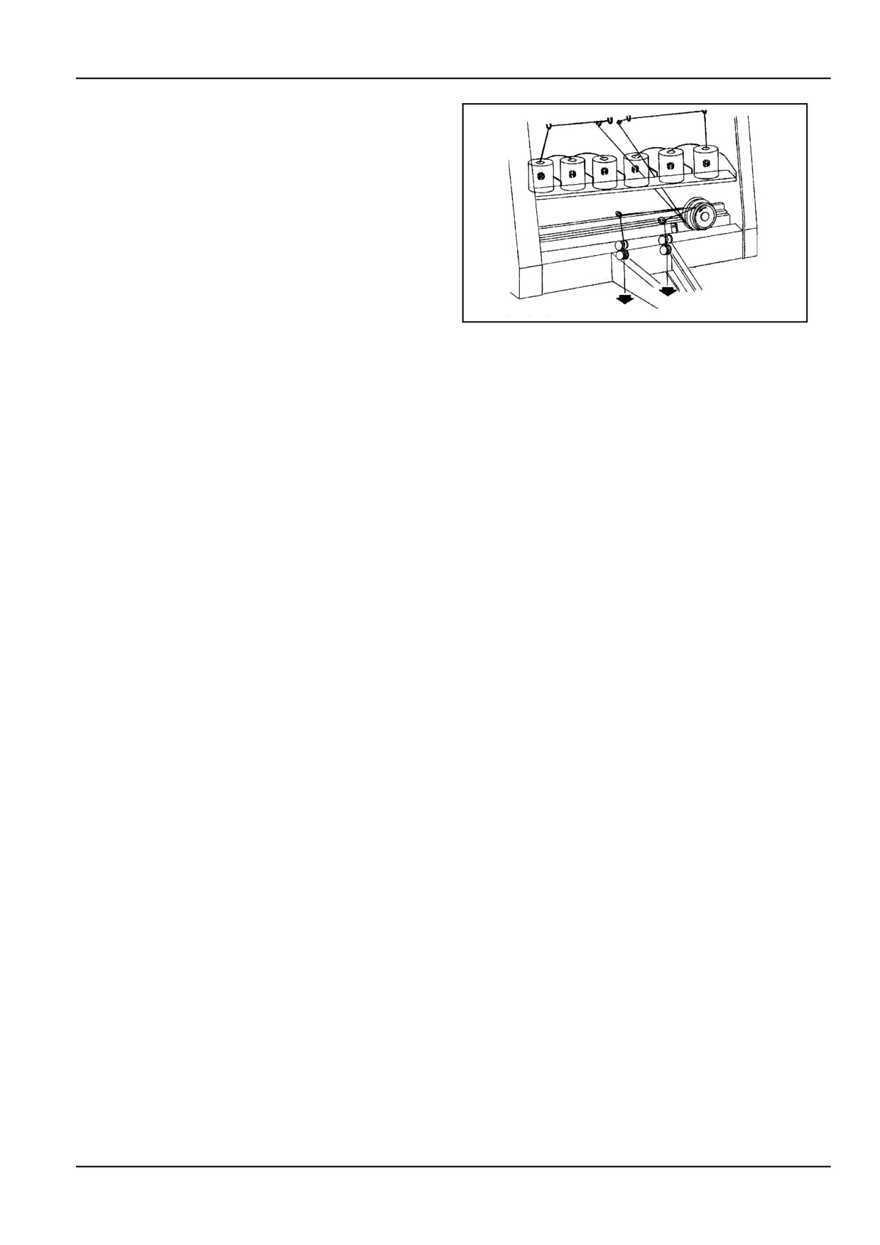
The twine storage box can carry up to 6 balls of twine,
depending on twine ball size:
•
4 balls of 285 mm (11.2 in) diameter
•
5 balls of 270 mm (10.6 in) diameter
•
6 balls of 225 mm (8.9 in) diameter
ZIL10FCRB777AAA
1
Open the front upper access door and place 2 to 6 twine
balls in the storage box, as shown in Figure 1.
If 6 balls are used, tie the inside end of each outer ball C
directly to the outside end of ball B. Tie the inside end of
ball B to the outside end of ball A, after routing it through
the metal eyelet (1) in the twine box roof. Tie the twine
tails together with a small square knot and cut off the tails
of this knot.
Twine ball divider plates (2) assist in keeping the twine
balls in place. They can be removed and relocated in
other holes to hold 6 or 5 twine balls in place. When 4
balls of 285 mm (11.2 in) are used, only the middle divider
plate can be used.
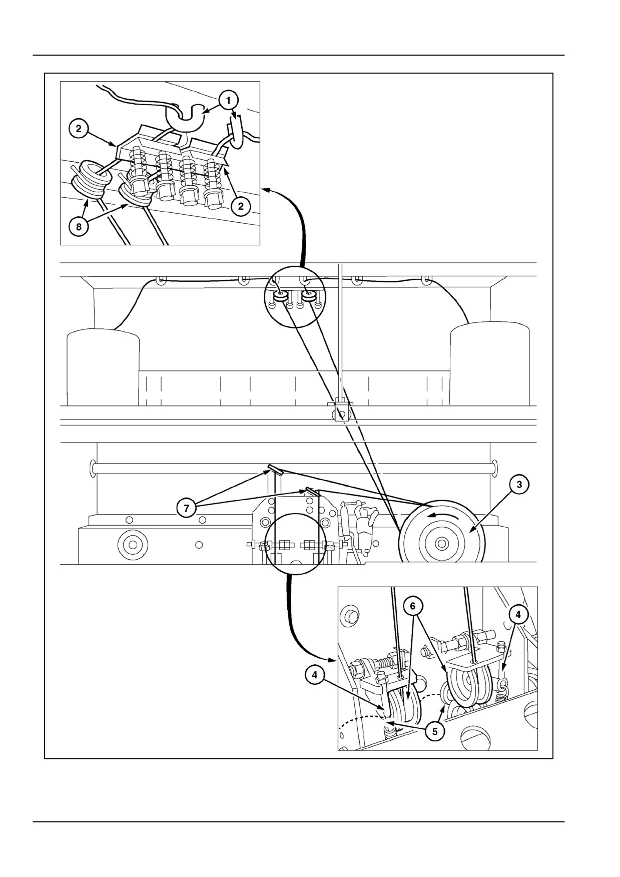
Figure 3 (only 2 balls are installed for clarity)
Route the end of each twine ball through their respective
eyelet (1), through the twine tensioner (2) and through the
porcelain guide (8).
Then wrap the twine around the twine pattern pulley (3),
route it through the eyelet (7), in between both feed rolls
(6) and through the eyelet (5): the last part of this proce-
dure is made easier by the possibility of turning the rolls
(6) upwards, after shifting the threaded rod (4) forwards.
Leave a tail of about 15 - 20 cm.
NOTE: The pattern pulley has 6 twine grooves with 3 dif-
ferent diameters, 2 grooves per diameter. It is very im-
portant to always wrap both twines around the same di-
ameter, but using different grooves. When wrapping the
twines around the pattern pulley, make sure the left and
right twines do not cross each other (risk of entangle-
ment). After having routed the twines correctly, take up
slack in the twine routing between the twine tensioners
and the feed rolls.
6 - 16
6 - WORKING OPERATIONS
Refer to the twine instruction decal fitted to the machine
and following illustrations for correct the twine installation.
ZIL10FCRB834AAA
2
6 - 17
6 - WORKING OPERATIONS
ZIL10FCRB001HAA
3
6 - 18
6 - WORKING OPERATIONS
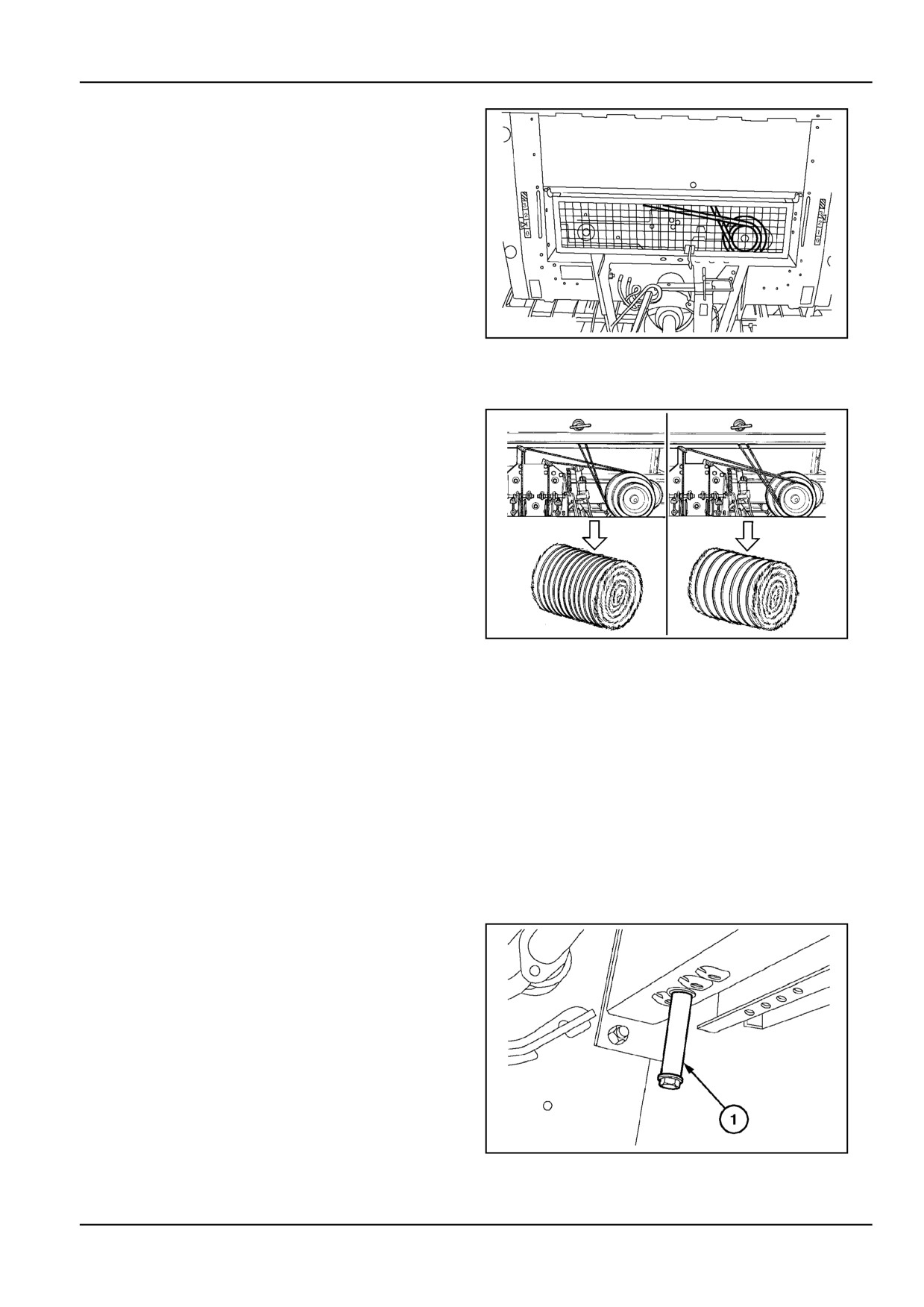
Figure 4
Close the front access doors and watch rotation and
standstill of the twine pattern pulley through the grid
guard.
ZIL10FCRB778AAA
4
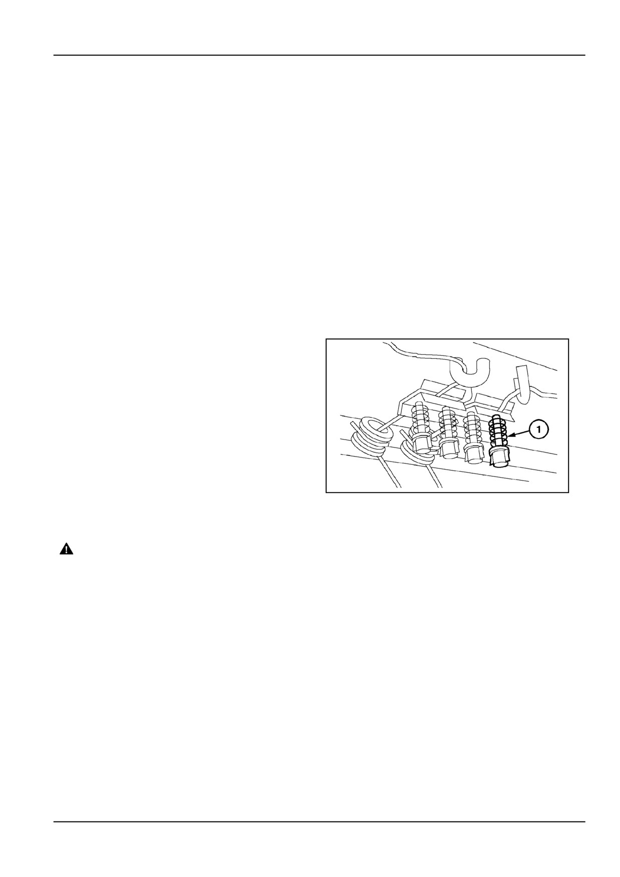
Number of twine wraps
The pattern pulley has a double twine groove at 3 different
diameters.
The larger the twine groove diameter, the higher the num-
ber of wraps that will be placed around the bale.
The smaller the diameter, the lower the number of twine
wraps that will be placed around the bale.
Every groove roughly corresponds with a certain number
of twine wraps:
•
Small diameter groove = 14 wraps
•
Middle diameter groove = 18 wraps
ZIL10FCRB832AAA
5
•
Large diameter groove = 22 wraps
NOTE: The specified number of wraps only serves as a
guidance. The real number of wraps will be determined
by the amount of slip of the twines on the pattern pulley.
This depends on a number of external factors such as
temperature, type of twine used and twine tension.
The number of wraps is independent of the PTO speed
during wrapping, as the wrap cycle is driven by the running
twines. Altering the PTO speed during wrapping will only
change the duration of the wrap cycle. Therefore, it is
advised to keep the PTO speed at 540 RPM.
TWINE PLACEMENT
To control twine placement at the bale's edges, adjustable
twine stops (1) can be relocated in 4 different positions.
This requires the use of a spanner.
Viewed from the inside
ZIL10FCRB780AAA
6
6 - 19
6 - WORKING OPERATIONS
TWINE WRAPPING PROCESS
1.
After a bale has been formed in the bale chamber
the full bale alarm will sound (optional). Engage the
wrapping cycle manually (using the starting cord) or
electrically (from the control box) and stop the tractor
forward motion.
DO NOT DISENGAGE THE PTO
2.
Once the twine has been picked up by the rotating
bale:
Release the Starting cord or
Action the Wrapper switch.
From now on, the wrap cycle runs completely auto-
matically.
3.
Watch the spreader hooks move to the middle to
pick up the running twines. Then they will move
to the outside, lay the end wraps, change direction
and move to the middle again where the twines will
be cut by the twine knives. During the wrap cycle,
watch for rotation of the pattern pulley and proper
guidance of the running twine.
NOTE: If a twine is not picked up by the bale or by
one of the spreader hooks, the bale will be wrapped
only on one side. Do not eject the bale, but proceed
as follows:
WARNING
Entanglement hazard!
Disengage the Power Take-Off (PTO), turn off
the engine, and remove the key. Wait for all
movement to stop before leaving the opera-
tor's position. Never adjust, lubricate, clean,
or unplug machine with the engine running.
Failure to comply could result in death or se-
rious injury.
W0227A
A. Leave the tractor and cut the twines manually.
B. Remove the twines from the pattern pulley and
rotate the pulley manually and COUNTER CLOCK-
WISE to finish the cycle and bring the spreader
hooks back to the home position (spreader hooks
moving to the middle as the twine starts running).
ALWAYS rotate the pulley counter-clockwise.
C. Reroute the twines as described in "Loading twine".
D. Get back in the tractor. Restart the tractor, reengage
the PTO and restart the wrap cycle while feeding a
little crop into the pickup.
6 - 20
6 - WORKING OPERATIONS
4.
When wrapping is finished and the twines are cut,
the pattern pulley will stop turning.
5.
Open the tailgate to eject the bale. Do not disen-
gage the PTO
6.
Close and latch the tailgate. Watch the density in-
dicators fall back to "zero" density. On machines
equipped with the electric control box system (stan-
dard on wide pickup models, accessory on standard
pickup models), a short "beep" will be heard as the
tailgate latches.
7.
Check the result for bale density and wrap pattern.
If the wrap pattern is not acceptable, change the
pattern on the pulley, or change the placement of the
end wraps by relocating the twine stops. Continue
baling.
Twine Installation [25789153]
Twine wrapping
In extreme conditions, such as very dry and slippery straw,
the twine tails may have difficulties to start on the bale. In
these conditions, do not stop immediately at the "full bale"
signal (visual or audible), but keep feeding the windrow at
reduced forward speed until the twines are picked up by
the bale. Watch the start of both twines which is visible
through the front guard. Then stop immediately to let the
entire wrap cycle take place.
Too much twine tension will cause the twine to depress
into the bale and may result in excess spoilage in those
areas. In this case, release the tension on the twine ten-
sioners (1).
ZIL10FCRB782AAA
1
Twine fails to cut
1.
Ensure the spreader hooks are in or have passed
the home position, and the tractor PTO is stopped.
WARNING
Knife hazard!
2.
Open the front grid guard and lock it in the open
Use care handling sharp components. Always
position.
wear appropriate Personal Protective Equip-
3.
Reach over the main frame cross beam and cut the
ment (PPE), including heavy gloves.
twine with a pocket knife.
Failure to comply could result in death or se-
Mind the twine wrapper knives.
rious injury.
W0274A
6 - 21
6 - WORKING OPERATIONS
Bale shape
The final bale shape is completely controlled by the op-
erator. Feeding the material as specified previously will
reduce the number of odd-shaped bales. Barrel-shaped
bales result when too much material is fed into the centre
of the bale. Cone-shaped bales will result if less material
is placed on one side of the bale, compared to the other
side.
In both cases, a bale is produced with poor handling and
weathering characteristics. Certain areas on the bale will
not be dense enough to keep rain and snow from penetrat-
ing deep into the bale. Learn to feed the material equally
into both ends of the bale.
To make tight weather-resistant bales, feed the material at
a rate which allows the bale to pack uniformly. Weave on
the windrow as necessary to fill the ends of the bale. Wrap
the bale with a sufficient number of wraps to maintain bale
integrity after ejection.
Bale Storage
When storing bales outside, place the bales in an area
which is higher than the surrounding ground level, rela-
tively dry, with ample sun exposure and air movement.
Allow 0.6 - 1.0 m (23.62 - 39.37 in) space on all sides of
the bale for air movement. Place the bales so prevailing
winds blow against the round portion of the bale and not
the ends.
Bales may also be stored in rows end to end, with 0.6 -
1.0 m (23.62 - 39.37 in) between rows.
6 - 22
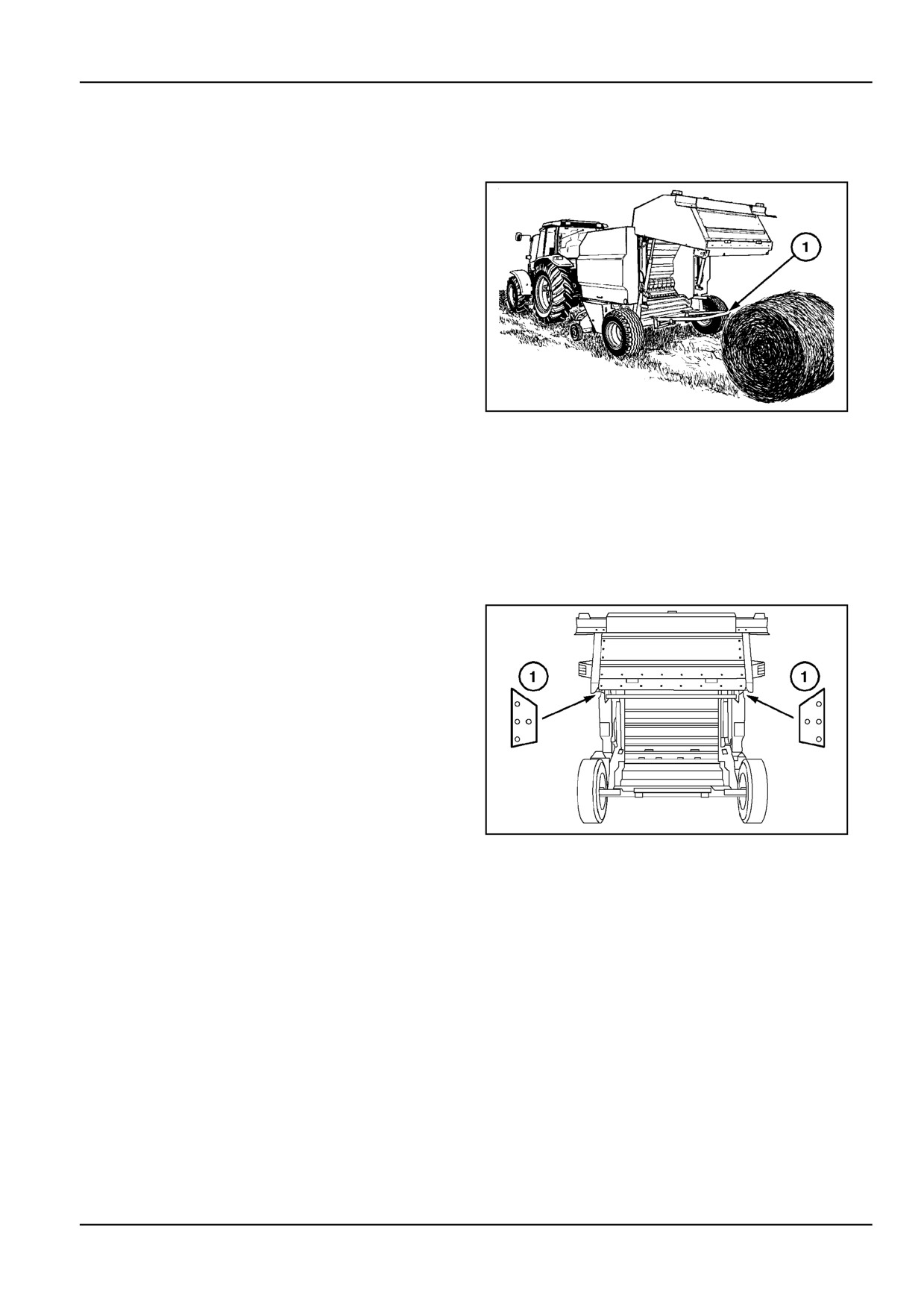
6 - WORKING OPERATIONS
Bale ejection [30275497]
Bale ejection
When the twine wrap cycle is finished, the pattern pulley
will stop turning as the twines are cut. At this time, operate
the tractor hydraulics to open the tailgate and eject the
bale.
The bale ejector (1) (accessory) rolls the bale out of the
bale chamber far enough to allow closing of the tailgate
without having to move the tractor forward.
If the bale does not roll far enough to allow the tailgate
to be closed, increase the tension on the bale ejector
springs. If the bale rolls too far, which may result in un-
rolling of the twines, then decrease the tension on the bale
ejector springs.
ZIL10FCRB118AAA
1
For machines not equipped with a bale ejector, back up
the tractor a few metres prior to bale ejection. After eject-
ing the bale, move the tractor forward again, thus prevent-
ing the tailgate from closing on the ejected bale.
ATTENTION: Never eject or store round bales where they
could roll downhill. Make sure the handling equipment will
not upset and will hold the bales in all operating condi-
tions.
In extreme cases (e.g. bale sticking in the bale chamber),
it may be necessary to:
•
Investigate if the tractor has sufficient hydraulic
power to open the tailgate quickly enough.
•
Decrease full bale density.
•
Install extra wedging plates (1) underneath the ex-
isting plates left and right inside the tailgate (Figure
2).
Close and latch the tailgate and watch the density indica-
tors fall back to "zero" density.
ZIL10FCRB781AAA
2
On machines equipped with the electric control box sys-
tem (optional), a short "beep" will be heard as the tailgate
latches.
6 - 23
6 - WORKING OPERATIONS
6 - 24

7 - MAINTENANCE
7 - MAINTENANCE
GENERAL INFORMATION
Lubrication [25790830]
Your baler is designed to require a minimum of lubrication.
Before greasing always wipe any dirt from the grease fit-
However, regular lubrication is the best insurance against
tings and then apply a good grade of grease. Use General
delays and repairs and greatly increases the life of the
Purpose grease classified under NLGI Class 2. All points
machine.
except those with special notations should be lubricated
until the grease is forced out around the bearings, and
All gearboxes and reservoirs should be checked for leak-
then excess grease should be wiped off.
age daily.
Use only top grade lubricants stored in clean vessels.
Lubrication chart
Servicing
Amount/unit
Lubricant
International
Item
Brand name
Specification
interval
(liters)
grade
specification
10 h: daily
-
NEW
50 h: weekly
-
HOLLAND
Grease fittings
AMBRA GR-9
NH710A.
NLGI 2.
-
400 h: annually
-
MULTI-PURPOSE
GREASE
DIN 51524
NEW HOL-
part2 HV 46
LAND AMBRA
NH646BV
Chains
10 h: daily
MV 46.
ISO VG 46
HYDROSYS-
NH646.
API CE-MIL-L-
TEM 46 BIO-S.
2104E
NEW HOL-
LAND AM-
BRA HY-
DIN 51524
DROSYSTEM
part2 HV 46
Automatic
NH646BV
Daily check
3 l (0.8 US gal)
46 BIO-SNEW
MV 46.
ISO VG 46
chain oiler
NH646.
HOLLAND
API CE-MIL-L-
AMBRA HY-
2104E
DROSYSTEM
46 BIO-S.
NEW
Main drive
HOLLAND
API GL5M
Annually
1 l (0.3 US gal)
NH520A.
SAE 85W-140.
gearbox
AMBRA
MIL-L-2104 E
HYPOIDE 90.
NEW
Linkages,
HOLLAND
API GL5
threaded rods
Monthly
-
NH520A.
SAE 80W-90.
AMBRA
MIL-L-2105 D
and pivots
HYPOIDE 90.
7 - 1
7 - MAINTENANCE
Adjustments and maintenance
WARNING
Entanglement hazard!
Disengage the Power Take-Off (PTO), turn off the engine, and remove the key. Wait for all movement
to stop before leaving the operator's position. Never adjust, lubricate, clean, or unplug machine with
the engine running.
Failure to comply could result in death or serious injury.
W0227A
DANGER
Unexpected movement!
Make sure parking brake is applied. Secure machine with wheel chocks.
Failure to comply will result in death or serious injury.
D0013A
DANGER
Crush hazard! The tailgate may close faster than you can move away.
ALWAYS make sure the tailgate lockout valves are in the OFF (locked) position before working under
a raised tailgate. In the event of a sudden loss of hydraulic pressure, the tailgate will fall if the lockout
valves are not engaged. Stand clear of the tailgate before disengaging the lockout valves.
Failure to comply will result in death or serious injury.
D0002A
This section contains instructions needed to adjust the
After lubricating, servicing or adjusting the baler, make
baler to meet varying crop and operating conditions. The
sure all tools and equipment have been removed before
procedures attempt to define the requirements imposed
operating the baler.
by the varying conditions and to give the adjustable limits.
Reinstall or close all guards after carrying out lubrication
A maintenance-quick reference chart is provided at the
or maintenance work and before operating the baler.
end of this section.
Hydraulic system maintenance
Very little actual maintenance is required to keep the baler
in the field. By making a thorough inspection at the time
Hydraulic hoses are an important safety element in
your baler is lubricated, only minor adjustments will be
modern machinery. However, hose characteristics alter
required to keep the baler operating.
under pressure, thermal and UV light load over the
years. Therefore, most hoses now have a production
Periodically inspect all bolts, sprockets and bearing lock
date printed on the metal clamp bushing which allows to
collars to make sure they are tight.
determine the age.
When tightening bolts, check for required torque values.
Legislation in certain countries and good practice requires
Do not overtighten bolts as this may cause them to fail
that the hydraulic hoses are replaced when they become
during operation.
6 years old.
Before making any adjustments or performing
Tailgate lift system hydraulic pickup lift sys-
maintenance work on the baler, proceed as follows:
tem
•
Disengage the PTO drive
•
Engage the tractor hand brake
Check for oil leaks or damaged hoses and tubes daily.
Tighten fittings or replace components as necessary.
•
Stop the tractor engine
Make sure the hoses are not near to or contacting any
•
Turn the monitor power OFF, unless instructed oth-
moving parts on the baler or tractor. Check the cylinders
erwise, to allow adjustments to be made.
for leakage and replace the seals, if necessary.
•
Ensure all rotating parts have come to a complete
standstill.
7 - 2

7 - MAINTENANCE
Torque charts - Minimum tightening torques for normal assembly
[34433528]
METRIC NON-FLANGED HARDWARE
NOM.
LOCKNUT
LOCKNUT
SIZE
CL.8
CL.10
CLASS 8.8 BOLT and
CLASS 10.9 BOLT and
W/CL8.8
W/CL10.9
CLASS 8 NUT
CLASS 10 NUT
BOLT
BOLT
PLATED
PLATED
UNPLATED
UNPLATED
W/ZnCr
W/ZnCr
2.2 N·m (19 lb
2.9 N·m (26 lb
3.2 N·m (28 lb
4.2 N·m (37 lb
2.9 N·m (26 lb
M4
2 N·m (18 lb in)
in)
in)
in)
in)
in)
4.5 N·m (40 lb
5.9 N·m (52 lb
6.4 N·m (57 lb
8.5 N·m (75 lb
5.8 N·m (51 lb
M5
4 N·m (36 lb in)
in)
in)
in)
in)
in)
7.5 N·m (66 lb
10 N·m (89 lb
11 N·m (96 lb
15 N·m (128 lb
6.8 N·m (60 lb
10 N·m (89 lb
M6
in)
in)
in)
in)
in)
in)
18 N·m (163 lb
25 N·m (217 lb
26 N·m (234 lb
35 N·m (311 lb
17 N·m (151 lb
24 N·m (212 lb
M8
in)
in)
in)
in)
in)
in)
49 N·m (36 lb
70 N·m (51 lb
33 N·m (25 lb
48 N·m (35 lb
M10
37 N·m (27 lb ft)
52 N·m (38 lb ft)
ft)
ft)
ft)
ft)
85 N·m (63 lb
121 N·m (90 lb
58 N·m (43 lb
83 N·m (61 lb
M12
64 N·m (47 lb ft)
91 N·m (67 lb ft)
ft)
ft)
ft)
ft)
158 N·m (116 lb
210 N·m (155
225 N·m (166 lb
301 N·m (222
143 N·m (106 lb
205 N·m (151 lb
M16
ft)
lb ft)
ft)
lb ft)
ft)
ft)
319 N·m (235 lb
425 N·m (313
440 N·m (325 lb
587 N·m (433
290 N·m (214 lb
400 N·m (295 lb
M20
ft)
lb ft)
ft)
lb ft)
ft)
ft)
551 N·m (410 lb
735 N·m (500
762 N·m (560 lb
1016 N·m (750
501 N·m (370 lb
693 N·m (510 lb
M24
ft)
lb ft)
ft)
lb ft)
ft)
ft)
NOTE: M4 through M8 hardware torque specifications
are shown in pound-inches. M10 through M24 hardware
torque specifications are shown in pound-feet.
7 - 3
7 - MAINTENANCE
METRIC FLANGED HARDWARE
NOM.
CLASS 8.8
BOLT and
CLASS 10.9 BOLT and
LOCKNUT
LOCKNUT
SIZE
CLASS
8 NUT
CLASS
10 NUT
CL.8
CL.10
W/CL8.8
W/CL10.9
BOLT
BOLT
PLATED
PLATED
UNPLATED
UNPLATED
W/ZnCr
W/ZnCr
2.4 N·m (21 lb
3.2 N·m (28 lb
3.5 N·m (31 lb
4.6 N·m (41 lb
2.2 N·m (19 lb
3.1 N·m (27 lb
M4
in)
in)
in)
in)
in)
in)
4.9 N·m (43 lb
6.5 N·m (58 lb
7.0 N·m (62 lb
9.4 N·m (83 lb
4.4 N·m (39 lb
6.4 N·m (57 lb
M5
in)
in)
in)
in)
in)
in)
8.3 N·m (73 lb
11 N·m (96 lb
12 N·m (105 lb
16 N·m (141 lb
7.5 N·m (66 lb
11 N·m (96 lb
M6
in)
in)
in)
in)
in)
in)
20 N·m (179 lb
27 N·m (240 lb
29 N·m (257 lb
39 N·m (343 lb
18 N·m (163 lb
27 N·m (240 lb
M8
in)
in)
in)
in)
in)
in)
54 N·m (40 lb
77 N·m (56 lb
M10
40 N·m (30 lb ft)
57 N·m (42 lb ft)
37 N·m (27 lb ft)
53 N·m (39 lb ft)
ft)
ft)
93 N·m (69 lb
100 N·m (74 lb
134 N·m (98 lb
M12
70 N·m (52 lb ft)
63 N·m (47 lb ft)
91 N·m (67 lb ft)
ft)
ft)
ft)
174 N·m (128 lb
231 N·m (171
248 N·m (183 lb
331 N·m (244
158 N·m (116 lb
226 N·m (167 lb
M16
ft)
lb ft)
ft)
lb ft)
ft)
ft)
350 N·m (259 lb
467 N·m (345
484 N·m (357 lb
645 N·m (476
318 N·m (235 lb
440 N·m (325 lb
M20
ft)
lb ft)
ft)
lb ft)
ft)
ft)
607 N·m (447 lb
809 N·m (597
838 N·m (618 lb
1118 N·m (824
552 N·m (407 lb
M24
ft)
lb ft)
ft)
lb ft)
ft)
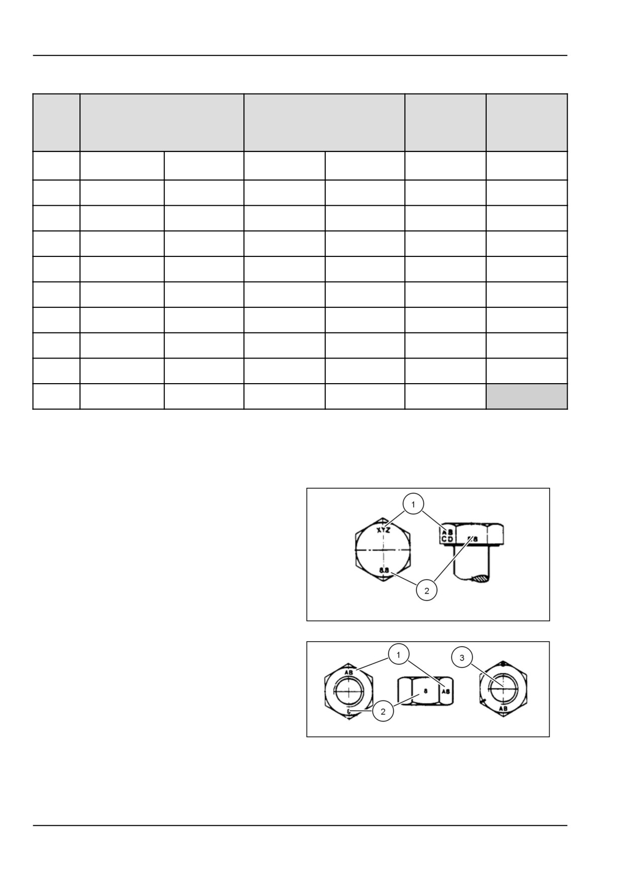
IDENTIFICATION
Metric Hex head and carriage bolts, classes
5.6 and up.
1.
Manufacturer's Identification
2.
Property Class
20083680
1
1.
Manufacturer's Identification
2.
Property Class
3.
Clock Marking of Property Class and Manufacturer's
Identification (Optional), i.e. marks 60 ° apart indi-
cate Class 10 properties, and marks 120 ° apart in-
dicate Class 8.
20083681
2
7 - 4

7 - MAINTENANCE
INCH NON-FLANGED HARDWARE
LOCKNUT
LOCKNUT
NOMINAL
SAE GRADE 5 BOLT
SAE GRADE 8 BOLT
GrB W/ Gr5
GrC W/ Gr8
SIZE
and NUT
and NUT
BOLT
BOLT
UN-
UN-
PLATED
PLATED
PLATED
PLATED
or
W/ZnCr
W/ZnCr
or PLATED
PLATED
GOLD
GOLD
SILVER
SILVER
8 N·m (71 lb
11 N·m (97 lb
12 N·m (106
16 N·m (142
12.2 N·m (109 lb
1/4
8.5 N·m (75 lb in)
in)
in)
lb in)
lb in)
in)
17 N·m (150
23 N·m (204
24 N·m (212
32 N·m (283
17.5 N·m (155 lb
25 N·m (220 lb
5/16
lb in)
lb in)
lb in)
lb in)
in)
in)
30 N·m (22 lb
40 N·m (30
43 N·m (31 lb
57 N·m (42 lb
3/8
31 N·m (23 lb ft)
44 N·m (33 lb ft)
ft)
lb ft)
ft)
ft)
48 N·m (36 lb
65 N·m (48
68 N·m (50 lb
91 N·m (67 lb
7/16
50 N·m (37 lb ft)
71 N·m (53 lb ft)
ft)
lb ft)
ft)
ft)
74 N·m (54 lb
98 N·m (73
104 N·m (77
139 N·m (103
1/2
76 N·m (56 lb ft)
108 N·m (80 lb ft)
ft)
lb ft)
lb ft)
lb ft)
107 N·m (79
142 N·m (105
150 N·m (111
201 N·m (148
156 N·m (115 lb
9/16
111 N·m (82 lb ft)
lb ft)
lb ft)
lb ft)
lb ft)
ft)
147 N·m (108
196 N·m (145
208 N·m (153
277 N·m (204
153 N·m (113 lb
215 N·m (159 lb
5/8
lb ft)
lb ft)
lb ft)
lb ft)
ft)
ft)
261 N·m (193
348 N·m (257
369 N·m (272
491 N·m (362
271 N·m (200 lb
383 N·m (282 lb
3/4
lb ft)
lb ft)
lb ft)
lb ft)
ft)
ft)
420 N·m (310
561 N·m (413
594 N·m (438
791 N·m (584
437 N·m (323 lb
617 N·m (455 lb
7/8
lb ft)
lb ft)
lb ft)
lb ft)
ft)
ft)
630 N·m (465
841 N·m (620
890 N·m (656
1187 N·m
654 N·m (483 lb
924 N·m (681 lb
1
lb ft)
lb ft)
lb ft)
(875 lb ft)
ft)
ft)
NOTE: For Imperial Units, 1/4 in and 5/16 in hardware through 1 in hardware torque specifications are shown in
torque specifications are shown in pound-inches. 3/8 in pound-feet.
7 - 5
7 - MAINTENANCE
INCH FLANGED HARDWARE
NOM-
LOCKNUT
LOCKNUT
SAE GRADE 5 BOLT and
SAE GRADE 8 BOLT and
INAL
GrF W/ Gr5
GrG W/ Gr8
NUT
NUT
SIZE
BOLT
BOLT
UNPLATED
PLATED
UNPLATED
PLATED
or PLATED
W/ZnCr
or PLATED
W/ZnCr
SILVER
GOLD
SILVER
GOLD
12 N·m (106 lb
13 N·m (115 lb
17 N·m (150 lb
12 N·m (106 lb
1/4
9 N·m (80 lb in)
8 N·m (71 lb in)
in)
in)
in)
in)
19 N·m (168 lb
25 N·m (221 lb
26 N·m (230 lb
35 N·m (310 lb
17 N·m (150 lb
24 N·m (212 lb
5/16
in)
in)
in)
in)
in)
in)
44 N·m (33 lb
47 N·m (35 lb
63 N·m (46 lb
3/8
33 N·m (25 lb ft)
30 N·m (22 lb ft)
43 N·m (32 lb ft)
ft)
ft)
ft)
71 N·m (52 lb
75 N·m (55 lb
100 N·m (74 lb
7/16
53 N·m (39 lb ft)
48 N·m (35 lb ft)
68 N·m (50 lb ft)
ft)
ft)
ft)
108 N·m (80 lb
115 N·m (85 lb
153 N·m (113
104 N·m (77 lb
1/2
81 N·m (60 lb ft)
74 N·m (55 lb ft)
ft)
ft)
lb ft)
ft)
117 N·m (86 lb
156 N·m (115
165 N·m (122
221 N·m (163
157 N·m (116 lb
9/16
106 N·m (78 lb ft)
ft)
lb ft)
lb ft)
lb ft)
ft)
162 N·m (119 lb
216 N·m (159
228 N·m (168
304 N·m (225
147 N·m (108 lb
207 N·m (153 lb
5/8
ft)
lb ft)
lb ft)
lb ft)
ft)
ft)
287 N·m (212 lb
383 N·m (282
405 N·m (299
541 N·m (399
261 N·m (193 lb
369 N·m (272 lb
3/4
ft)
lb ft)
lb ft)
lb ft)
ft)
ft)
462 N·m (341 lb
617 N·m (455
653 N·m (482
871 N·m (642
421 N·m (311 lb
594 N·m (438 lb
7/8
ft)
lb ft)
lb ft)
lb ft)
ft)
ft)
693 N·m (512 lb
925 N·m (682
979 N·m (722
1305 N·m (963
631 N·m (465 lb
890 N·m (656 lb
1
ft)
lb ft)
lb ft)
lb ft)
ft)
ft)
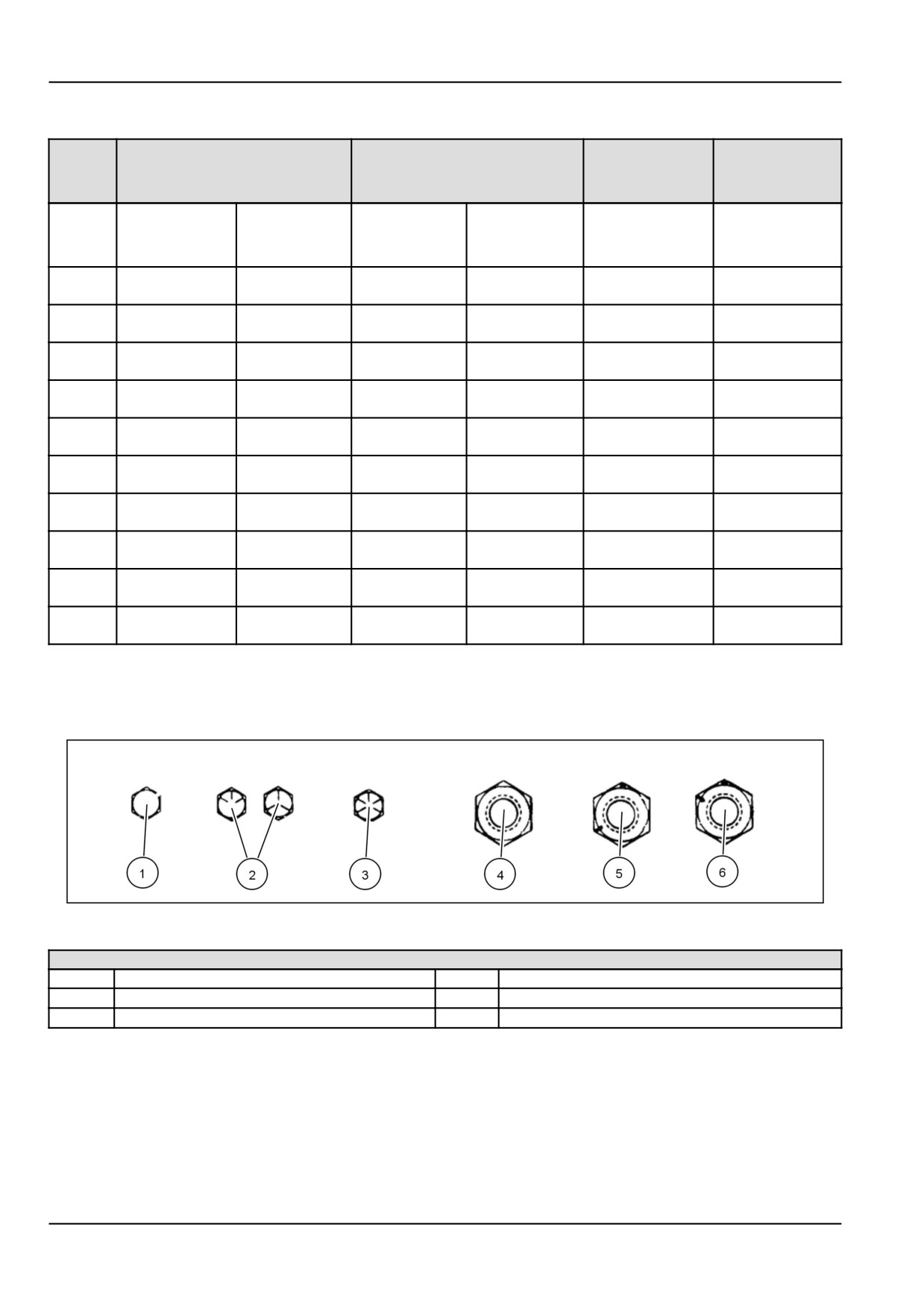
IDENTIFICATION
Inch Bolts and free-spinning nuts
20083682
3
Grade Marking Examples
SAE Grade Identification
1
Grade 2 - No Marks
4
Grade 2 Nut - No Marks
2
Grade 5 - Three Marks
5
Grade 5 Nut - Marks 120 ° Apart
3
Grade 8 - Five Marks
6
Grade 8 Nut - Marks 60 ° Apart
7 - 6