New Holland BR6080. OPERATOR’S MANUAL (2011) - page 1
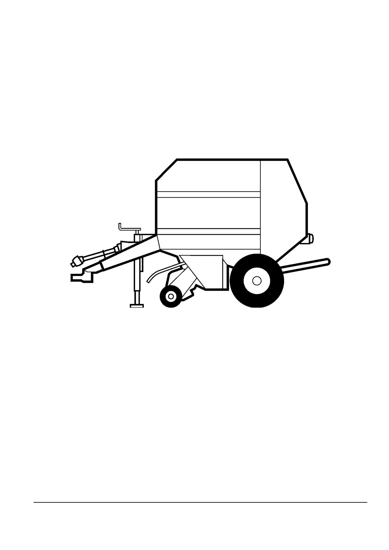
OPERATOR'S MANUAL
BR6080
Zed - BR6080OM-DRAFT
Issue date June 2011
EN
Contents
1 GENERAL INFORMATION
Foreword
1-1
Note to the Owner
1-4
Legal obligations
1-6
Twine Wrapper
1-7
Twine Wrapper
1-13
Bale density system
1-21
Tractor Requirements
1-25
Power take off (PTO)
1-26
Jack stand
1-27
Parking Brake
1-28
2 SAFETY INFORMATION
Safety rules
2-1
Safety decals
2-10
Safety Features
2-17
Tailgate
2-19
3 CONTROLS/INSTRUMENTS
Monitor Operation
Baler Operator Controls Control box (Optional)
3-1
4 OPERATING INSTRUCTIONS
COMMISSIONING THE UNIT
Machine safety
4-1
Tractor attachment
4-3
Tractor attachment
4-3
Hydraulic connections
4-13
Pick up
4-15
Bale counter
4-17
Tailgate
4-18
Electrical connections
4-19
STARTING THE UNIT
Machine preparation
4-21
PARKING THE UNIT
Parking the machine
4-21
5 TRANSPORT OPERATIONS
ROAD TRANSPORT
Towing the machine
5-1
PREPARING FOR ROAD TRANSPORT
Lifting the machine
5-3
6 WORKING OPERATIONS
GENERAL INFORMATION
Bale Formation Overview
6-1
Pick up
6-7
Baler Preparation
6-9
Driveline protection
6-9
Twine Wrapper
6-16
Twine Installation
6-21
Bale ejection
6-23
7
MAINTENANCE
GENERAL INFORMATION
Lubrication
7-1
Torque charts - Minimum tightening torques for normal assembly
7-3
Cam adjustment Cam follower replacement
7-7
Pick up Flotation - wide pickup
7-8
Windguard
7-8
Cam adjustment Cam follower bearing replacement
7-9
Twine Wrapper
7-10
Twine Installation
7-10
Spreader plates
7-12
Twine Installation
7-12
Twine Wrapper Knife
7-13
Conveyor Adjustments
7-13
Conveyor Adjustments
7-14
Feeder
7-15
Feeder
7-15
Conveyor Adjustments
7-16
Tailgate
7-17
Bale density
7-17
Bale density system
7-18
Bale Loader Sensor Adjustment
7-20
Bale ejection
7-20
Tailgate
7-21
Automatic oiling system
7-22
Hydraulic Hose Replacement Interval
7-24
Wheels and tires
7-25
Wheels and tires
7-26
MAINTENANCE CHART
Maintenance Chart
7-27
10 hours or daily Service
Chain and bar system - Lubricate
7-28
Front hitch
7-28
Floor Roll Drive Chain
7-29
Tailgate
7-29
Chain Drive
7-29
50 hours Service
Drive chains
7-30
Drive chains
7-30
Gearbox
7-31
PTO
7-31
Pick up
7-33
Drive chains
7-34
Bale density
7-34
Drive chains
7-34
Pick up
7-35
Pick up
7-37
Tailgate
7-37
Gearbox
7-38
Tailgate
7-38
100 hours Service
Twine Wrapper
7-39
1200 hours or 12 months Service
Wheels and tires
7-39
Hydraulic hoses Hose replacement
7-39
STORAGE
End of Season Parts Replacement
7-41
Preparing for Storage
7-41
Removing from storage
7-42
TROUBLESHOOTING
Round baler
7-43
8 SPECIFICATIONS
Overall Dimensions
8-1
9 ACCESSORIES
Optional equipment
9-1
10 FORMS AND DECLARATIONS
Delivery Report Customer Copy Customer copy
10-3
Delivery Report Dealer Copy Dealer copy
10-5
1 - GENERAL INFORMATION
1 - GENERAL INFORMATION
Foreword [25722765]
This manual has been prepared to assist you in the cor-
dard or as an accessory, may vary according to the coun-
rect procedure for running in, driving, operating, adjusting
try in which the equipment is to be used. Low cost con-
and maintaining your new machine.
figurations, as chosen by the customer, may deviate from
specifications given.
This machine has been designed and built to give maxi-
mum performance, economy and ease of operation under
Several illustrations in this manual show the safety guard-
a wide variety of crops and conditions.
ing or the additional guards, legally required by certain
countries, open or removed to illustrate better a particular
Prior to delivery, your machine was carefully inspected
feature or adjustment.
both at the factory and by your dealer to ensure that it
reaches you in optimum condition. To maintain this con-
The machine must not be used in this condition. For your
dition and ensure trouble-free operation it is important that
own safety, ensure that all guards are closed or replaced
routine services, as specified in this manual, are carried
before operating the machine.
out at the recommended intervals.
Owner assistance
Before attempting to drive or operate your machine, read
this manual carefully (especially chapter covering the
We at New Holland and your New Holland Dealer want
Safety Precautions) and keep it in a convenient place for
you to be completely satisfied with your investment. Nor-
future reference.
mally your dealer's Service Department will handle any
problems with your equipment. Sometimes, however,
"Left" and "right" used throughout this manual are deter-
misunderstanding can occur. If your problem has not
mined from the rear, facing in the direction of travel of the
been handled to your satisfaction, we suggest contacting
machine during operation.
the owner or General Manager of the dealership, ex-
plaining the problem, and requesting assistance. When
If at any time you require advice concerning your ma-
additional assistance is needed, your dealer has direct
chine, do not hesitate to contact your authorised dealer.
access to our branch office.
Who has factory-trained personnel, genuine service parts
and the necessary equipment to carry out your service re-
quirements.
Improvements and changes
NOTICE: This machine has been designed and built ac-
The company is continually striving to improve its prod-
cording to the European Directive 2006/42/EC.
ucts, and therefore reserves the right to make improve-
Always use genuine New Holland Service Parts when ser-
ments and changes when it comes practical and possible
vicing and repairing your machine and do not modify your
to do so, without incurring any obligation to make changes
machine without a written permission of the manufacturer.
or additions to the equipment sold previously.
Failure to do so will void the responsibility of the manufac-
turer.
All data given in this manual is subject to production vari-
ations.
An EC Declaration of Conformity is separately delivered
NOTICE: Operating and service messages displayed
with your machine. Store this EC Declaration into the
on the electronic operating panel may vary from what
storage space for your Operator's Manual.
is shown in the Operator's Manual. Should this occur
Check local road legislation before driving the baler on
adhere to the latest instruction on the electronic operating
public roads.
panel.
Dimensions and weights are approximate only and the
When operating interchangeable New Holland built
illustrations do not necessarily show balers in standard
equipment, ensure the equipment is CE approved.
condition. For exact information about any particular ma-
chine please consult your Dealer.
As this publication is distributed throughout our interna-
tional network, the equipment illustrated, either as stan-
1 - 1
1 - GENERAL INFORMATION
Accessories
Important environmental considerations
Your machine has been designed to operate in a wide
Soil, air and water are vital factors of agriculture and of
variety of crops and conditions. Nevertheless Additional
life in general. Where legislation does not yet rule the
equipment may, in certain cases, be required to improve
treatment of some of the substances, which are required
the machine performance. A list of this additional equip-
by advanced technology, common sense should govern
ment is given in the "Accessories" section in this manual.
the use and the disposal of the products of a chemical
and a petrochemical nature.
Service parts and accessories
The following are recommendations, which may be of as-
sistance:
Genuine service parts and accessories have been spe-
cially designed for your machine.
Become acquainted with and respect the relative legisla-
tion applicable in your country.
We would like to point out that "non-genuine" parts and
accessories have not been examined and released by the
Where no legislation exists, obtain information from sup-
Company. The installation and/or use of such products
pliers of oils, fuels, antifreeze, cleaning agents, etc. for
could thus have negative effects upon the design char-
their effect on man and nature and for safe ways of stor-
acteristics of your machine and thereby affect its safety.
age, usage and disposal. Agricultural consultants will, in
The Company is not liable for any damage caused by the
many cases, be able to help you as well.
use of "non-genuine" parts and accessories.
Rely on your authorised dealer to supply you with genuine
Helpful hints
New Holland parts only. These parts are covered by our
warranty and will give you the best performance.
Avoid filling fuel tanks using jerrycans or inappropriate
pressurized fuel delivery systems which may cause con-
When ordering service parts, always quote the model and
siderable spillage.
serial number as well as the year of manufacture which is
printed on the manufacturer's identification plate.
In general, avoid skin contact with all oils, acids, solvents,
etc. Most of them contain substances which can be harm-
ful to your health.
Warranty
Use biodegradable oils for chain lubrication where oils
Your machine is warranted according to legal rights in
cannot be recuperated. In many countries rapeseed oils
your country and the contractual agreement with the sell-
or other agricultural lubricants have become available.
ing dealer. No warranty shall, however, apply if the ma-
chine has not been used, adjusted and maintained ac-
Modern oils contain additives. Do not burn contaminated
cording to the instructions given in this Operator's Man-
fuels and/or waste oils in ordinary heating systems.
ual.
Avoid spillage when draining off used engine coolant mix-
It is prohibited to carry out any modifications to the ma-
tures, engine, gearbox and hydraulic oils, brake fluids,
chine unless specifically authorised, in writing, by a New
etc. Do not mix drained brake fluids, fuels or coolant mix-
Holland representative.
tures with lubricants. Store them safely until they can be
disposed of in a proper way to comply with local legisla-
Lubricants
tion and available resources. They should not be allowed
to get into the soil but should be collected and disposed
Your dealer sells a selection of specially formulated lubri-
of safely.
cants based on own engineering specifications.
Do not open the air-conditioning system yourself; it con-
Recommended lubricants for your machine are listed in
tains gases, which should not be released into the air.
the Maintenance section of this manual.
Your dealer has a special extractor for this purpose and
will have to do the recharging of the system anyway.
Cleaning your machine
Repair any leaks or defects in the engine cooling or the
Your machine is a state-of-the-art machine with sophisti-
hydraulic system immediately.
cated, electronic controls. Even though every precaution
has been taken to safeguard electronic components and
Do not increase the pressure in a pressurized circuit as
connections, the pressure generated by some pressure
this may lead to bursting of the components.
washers is such that complete protection against water
ingress cannot be guaranteed.
Protect hoses during welding as penetrating weld splatter
may burn a hole or weaken them, causing the loss of oils,
When using a high pressure washer, do not stand too
coolant, etc.
close to the machine and avoid directing the jet at elec-
tronic components, electrical connections, breathers,
seals, filler caps, etc.
1
- 2
1 - GENERAL INFORMATION
Battery recycling
batteries and small "dry" batteries which may be used in
electric or electronic systems) to your New Holland Dealer
Batteries and electric accumulators contain various com-
who will ensure proper disposal or recycling. In certain
ponents which can damage the environment if they are
countries this is a legal requirement.
not properly recycled after usage. New Holland strongly
recommends that you return all used batteries (starting
1 - 3
1 - GENERAL INFORMATION
Note to the Owner [25657939]
Intended use
This Round Baler is designed to be towed by an agricul-
tural tractor and powered by the tractor's power take off.
It is intended to be used to pick up and bale forage and
straw crops including, but not limited to, mixed hay/grass
and lucerne, for agricultural purposes on cultivated land.
ALL OTHER PURPOSES ARE PROHIBITED.
Product improvements
We are continually striving to improve its products. We re-
serve the right to make improvements or changes when
it becomes practical and possible to do so, without incur-
ring any obligation to make changes or additions to the
equipment sold previously.
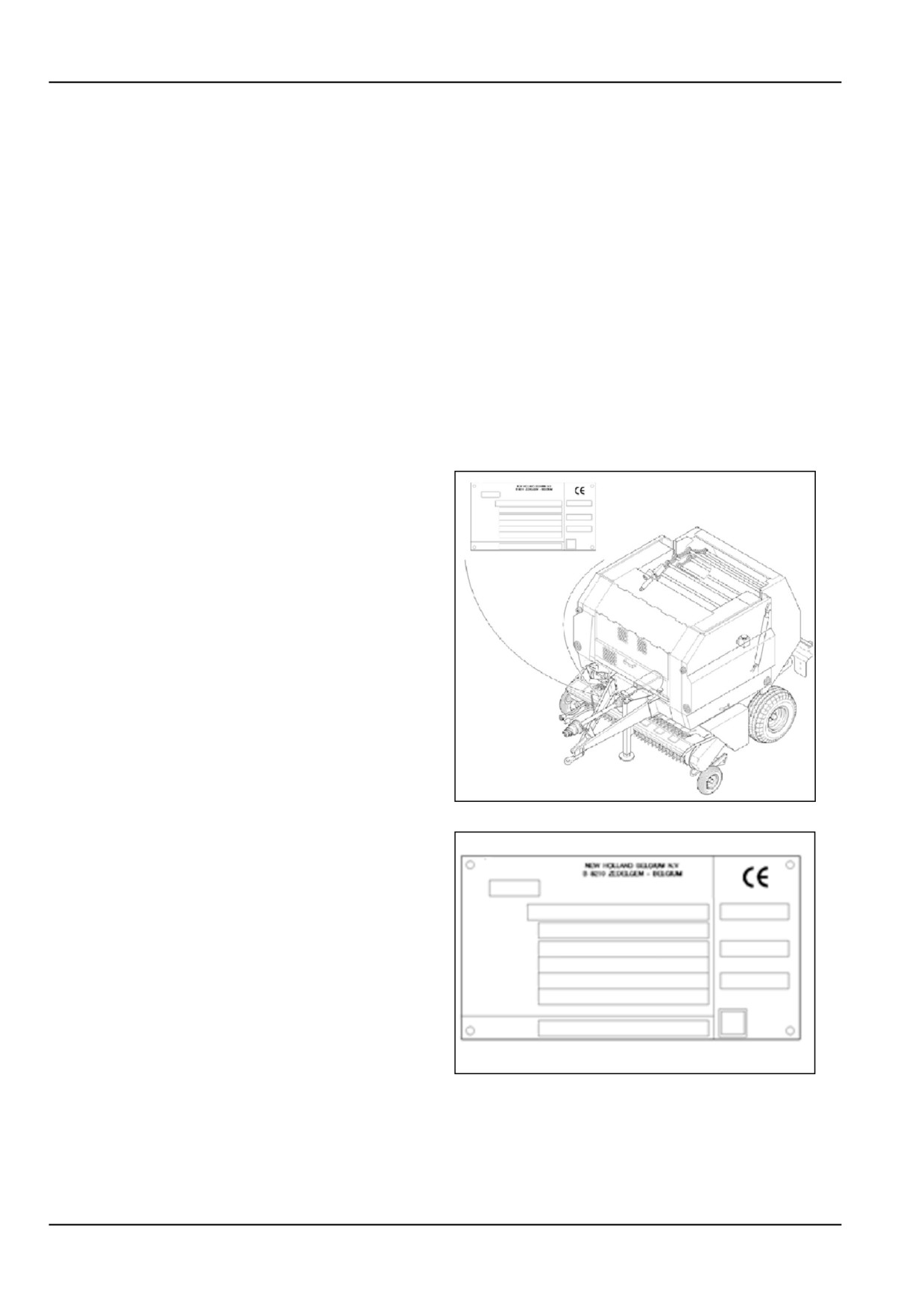
Product identification PIN plates
The model, serial number and year of manufacture are
stamped on a manufacturer's identification plate which is
located on the frame front cross beam, on the right of the
baler tongue.
The serial number is also stamped in the frame cross
beam just above the identification plate.
P1
1
Record below your machine serial number and year of
manufacture for quick reference:
Baler type
_______________________
_
Baler serial n°
_______________________
_
Year of manufacture
_______________________
_
Date machine first used
_______________________
_
Dealer's telephone n°
_______________________
_
P2
2
1 - 4

1 - GENERAL INFORMATION
Machine serial number 9 and 17 digit.
The machine is identified using currently a 9 digit serial
number which could look like 351720001, and can be
found on the PIN (Product Identification Number) plate.
The new serial number (where applied) will consist of 17
(alpha/numeric) digits which will be similar to the example:
HAF35100L0072000.
This includes the current 9 digit number as shown in the
following table.
9 D-
3
5
1
7
2
0
0
0
1
igit
17
H
A
F
3
5
1
0
0
L
0
0
7
2
0
0
0
1
Dig-
it
1
2
3
4
5
6
7
8
9
10
11
12
13
14
15
16
17
This new serial number can then be read and explained
as follows using example: HAF35100L00720001
Position one to three represents the World Manufacturer
Code (WMC).
(HAF) is the WMC for the Zedelgem - Belgium plant.
Position four to eight form the Machine Descriptor Section
alpha/numeric.
Position four and five are the identification of the model
within the product line (35) machine.
Position six (1) indicates the production assembly line
number, 1 = Zedelgem machine assembly line.
Position seven and eight (00) are used for specific ho-
mologation indications.
Position nine (L) is used as a check digit (Only charac-
ters). The calculation of this character is based on the
other sixteen digits from the serial number.
Position ten to seventeen (00720001) form the Machine
Indicator Section. alpha/numeric.
Position ten and eleven are not used (value is zero)
Position twelve up to fourteen (720) represents the batch
in which the machine was made.
Position fifteen to seventeen (001) represents the sequen-
tial number for each machine made within a batch.
001 = first machine built in batch 720.
1 - 5
1 - GENERAL INFORMATION
Legal obligations [25660187]
EC Declaration of Conformity
The document as well as the operator's manual should
also stay with the machine if it is traded again.
The manufacturer delivers the machine with a document
This baler has also been built to comply with additional
called "EC Declaration of Conformity" which guarantees
related European standards which include:
that the machine complies with the European Machinery
EN 15811:2009 Guard locks
Safety Directives.
EN 12965 PTO drive shafts and guards
This document will usually be found on the machine when
EN ISO 5674 Guards PTO drive shafts
the machine is originally supplied to you.
EN ISO 13849 Safety electronic systems
If not, it should be obtained from your dealer.
EN ISO 12100 Machinery safety general
The owner must carefully preserve this document to be
able to present it to Safety Inspection Authorities when
requested.
EC Declaration of Conformity
According to Directives 2006/42/EC & 2004/108/EC
We, CNH Belgium N.V.Leon Claeysstraat 3A B - 8210 ZEDELGEM (Belgium)
represented by Antoon Vermeulen,
Leon Claeysstraat 3A B - 8210 ZEDELGEM (Belgium)
declare under our sole responsibility, that the product:
Agricultural machine
Commercial Name and Model: New Holland BR6080
Denomination: BALER
Type: 544/1 or 1604
Serial Number:
to which this declaration relates, fulfills all the relevant provisions of Directives 2006/42/EC & 2004/108/EC,
amended by: ____________
For the relevant implementation of the provisions of the Directives, the following (harmonized) standards
have been applied:
• EN ISO 4254-1:2009
• EN ISO 14982:2009
• EN ISO 4254-11:2010
Place and date of the declaration: Zedelgem
Name and signature of authorized person:
Antoon Vermeulen
1 - 6
1 - GENERAL INFORMATION
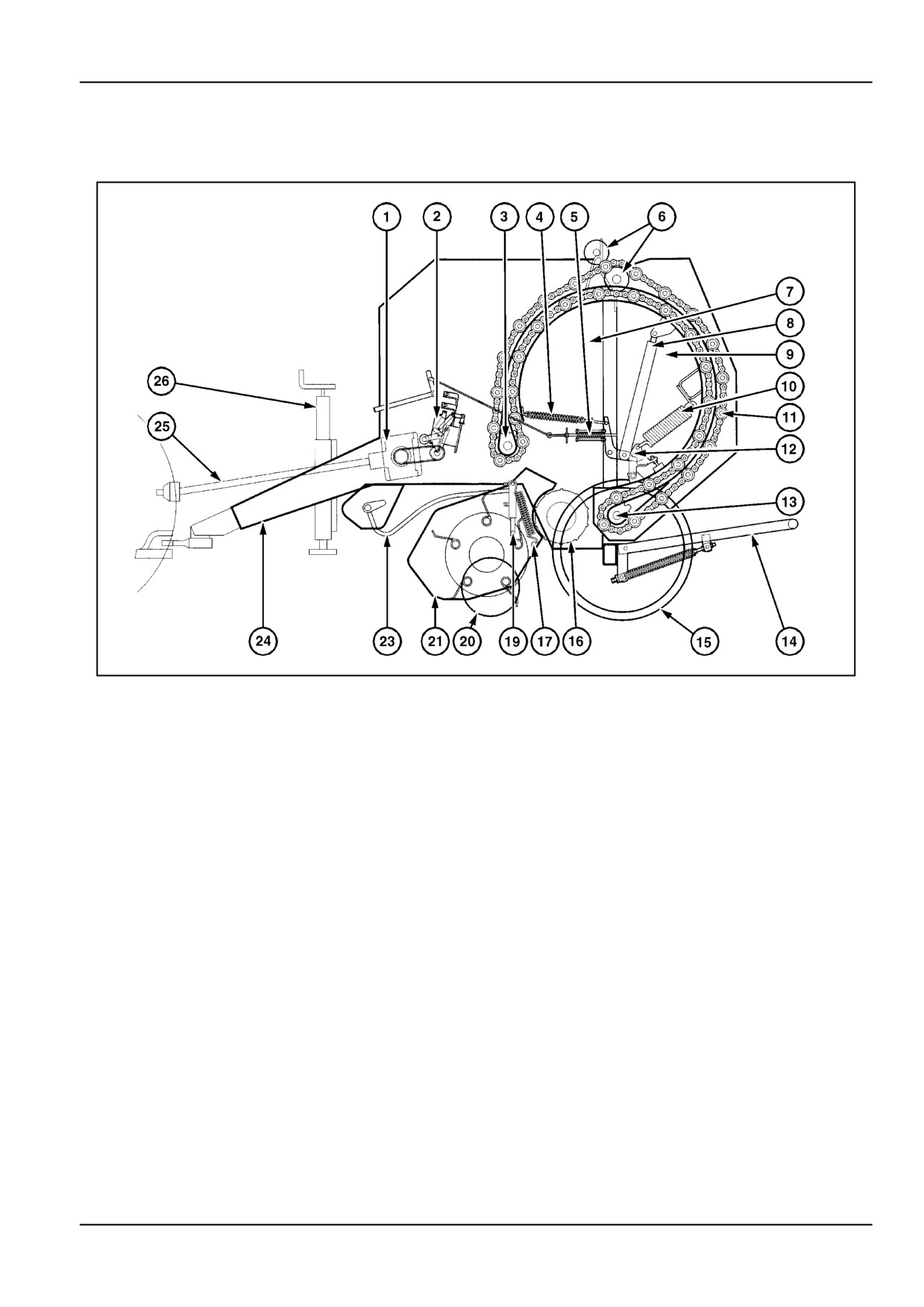
Twine Wrapper [25762101]
Basic components
ZIL10FCRB051FAA
1
Standard pickup models
1. Gearbox
14. Bale ejector [accessory]
2. Twine wrap mechanism
15. Ground wheel
3. Conveyor drive shaft
16. Floor roll
4. Tailgate latch spring
17. Pickup flotation spring
5. Density indicator mechanism
18. -
6. Conveyor idler rollers
19. Pickup lift cylinder [accessory]
7. Bale chamber
20. Pickup gauge wheel [accessory]
8. Tailgate cylinder
21. Pickup assembly
9. Tailgate
22. -
10. Density spring
23. Windguard
11. Conveyor chain and bars
24. Reversible hitch
12. Tailgate latch
25. Drive shaft with shearbolt protection
13. Conveyor tensioner idler
26. Jack
1 - 7
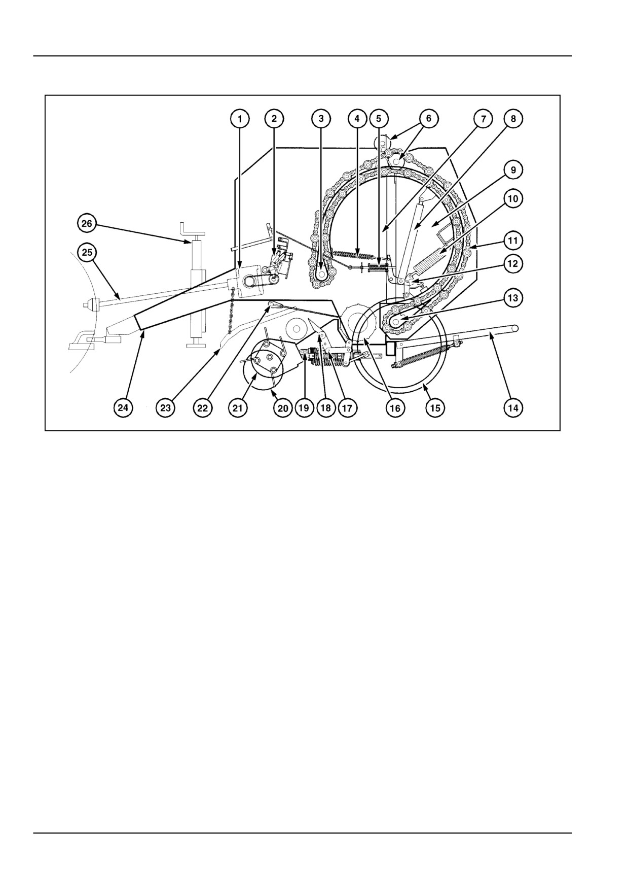
1 - GENERAL INFORMATION
Basic components
ZIL10FCRB040FAA
2
Wide pickup models
1. Gearbox
14. Bale ejector [accessory]
2. Twine wrap mechanism
15. Ground wheel
3. Conveyor drive shaft
16. Floor roll
4. Tailgate latch spring
17. Pickup flotation spring
5. Density indicator mechanism
18. Crank-type packer
6. Conveyor idler rollers
19. Pickup lift cylinder [accessory]
7. Bale chamber
20. Pickup gauge wheel [accessory]
8. Tailgate cylinder
21. Pickup assembly
9. Tailgate
22. Second windguard
10. Density spring
23. Windguard
11. Conveyor chain and bars
24. Reversible hitch
12. Tailgate latch
25. Drive shaft with shearbolt protection
13. Conveyor tensioner idler
26. Jack
1 - 8
1 - GENERAL INFORMATION
How the baler functions
ZIL10FCRB041FAA
3
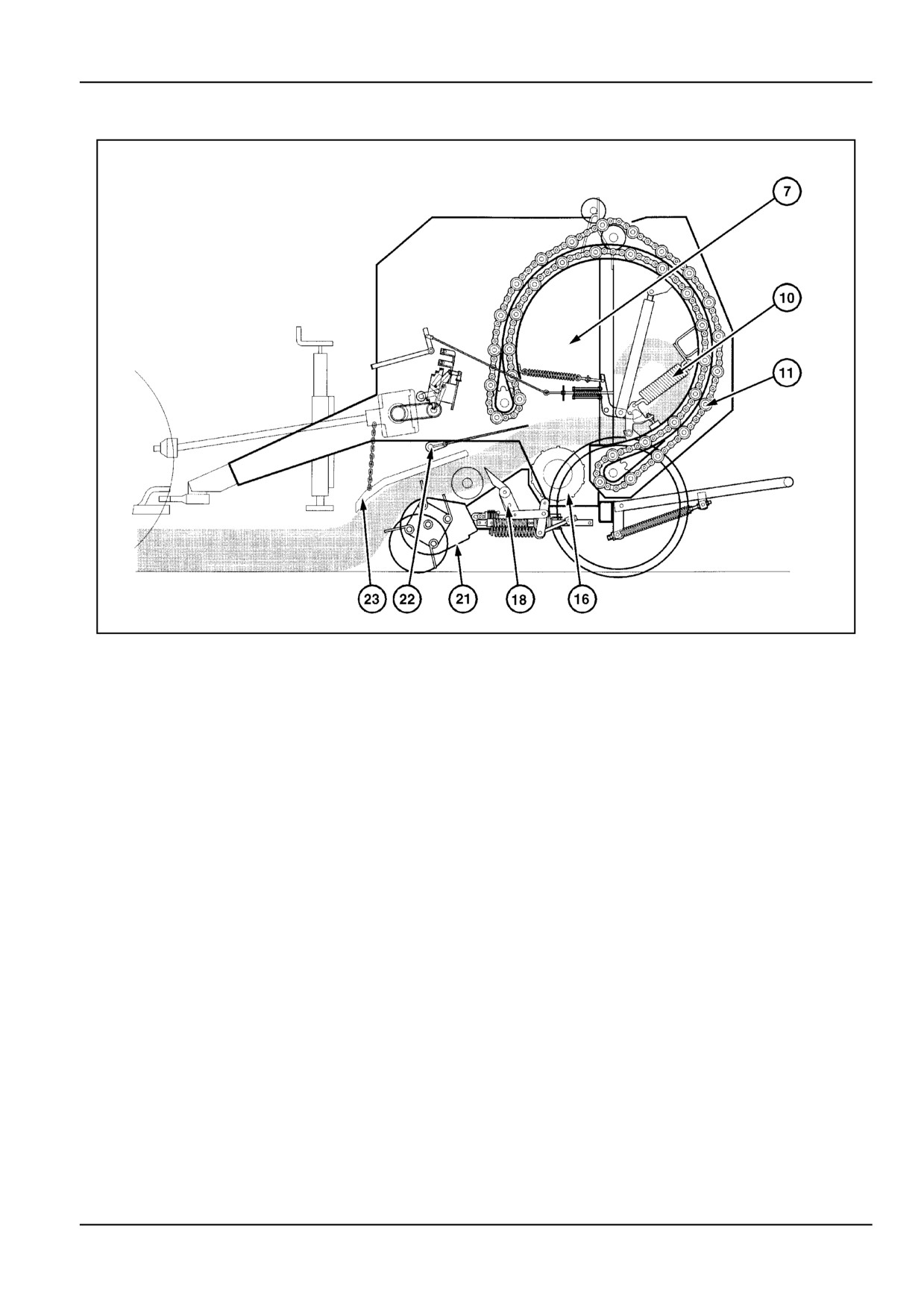
On wide pickup models, the pickup (21) equipped with
The floor roll (16) feeds the crop to the conveyor chain
cross conveying augers, feeds the crop to the packer
(11). Together they begin to form the bale inside the bale
feeder (18).
chamber (7).
The first and second windguard (22) and (23) are floating
At this time, the tailgate is closed and latched. The density
to hold the crop firmly above the pickup for positive feed-
springs (10) are retracted against their rubber stops.
ing.
The bale chamber (7) is filling up as crop feeds in. The
On the standard pickup models, the pickup feeds the crop
crop layer starts rolling packs loosely by its own weight
directly into the bale chamber. The floating windguard
and structure.
is adjustable in height to hold the crop firmly above the
pickup for positive feeding.
1 - 9
1 - GENERAL INFORMATION
ZIL10FCRB042FAA
4
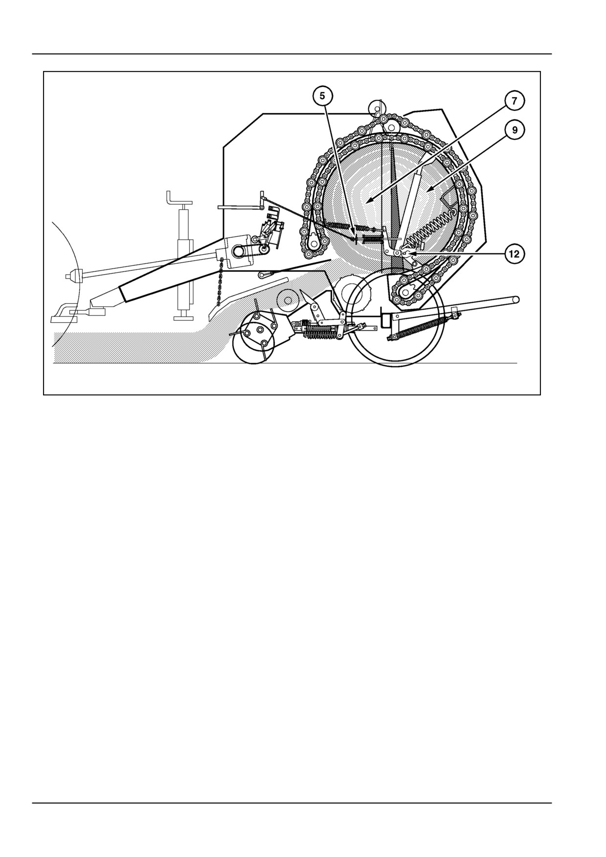
The bale chamber (7) is filled up with loosely packed crop.
The density indicator mechanism (23) will measure the
As more crop is fed in, the floor roll and conveyor chain
amount of tailgate opening and is linked to mechanical
begin to compact the bale until the desired density is
density indicators left and right in front of the machine.
reached. Most of the bale weight is carried by the floor
The operator has to watch these indicators to see when
roll.
the desired density is reached.
Contrarily, the compacting bale exerts pressure on the
As there is a density indicator mechanism on both sides,
tailgate (9) and tends to push the tailgate open. The tail-
they also assist the operator in filling the bale evenly on
gate is hooked up by the latch (12) attached to the main
both sides.
frame and the density spring (10) attached to the tailgate.
At this moment, the tailgate is slightly open but still held
The tailgate will slightly open, thereby pulling on both the
in the latch (12) on both sides of the machine.
left and right density springs (10).
The more the tailgate will open, the more the density
springs will be pulled and the higher the density of the
bale will be.
1 - 10
1 - GENERAL INFORMATION
ZIL10FCRB043FAA
5
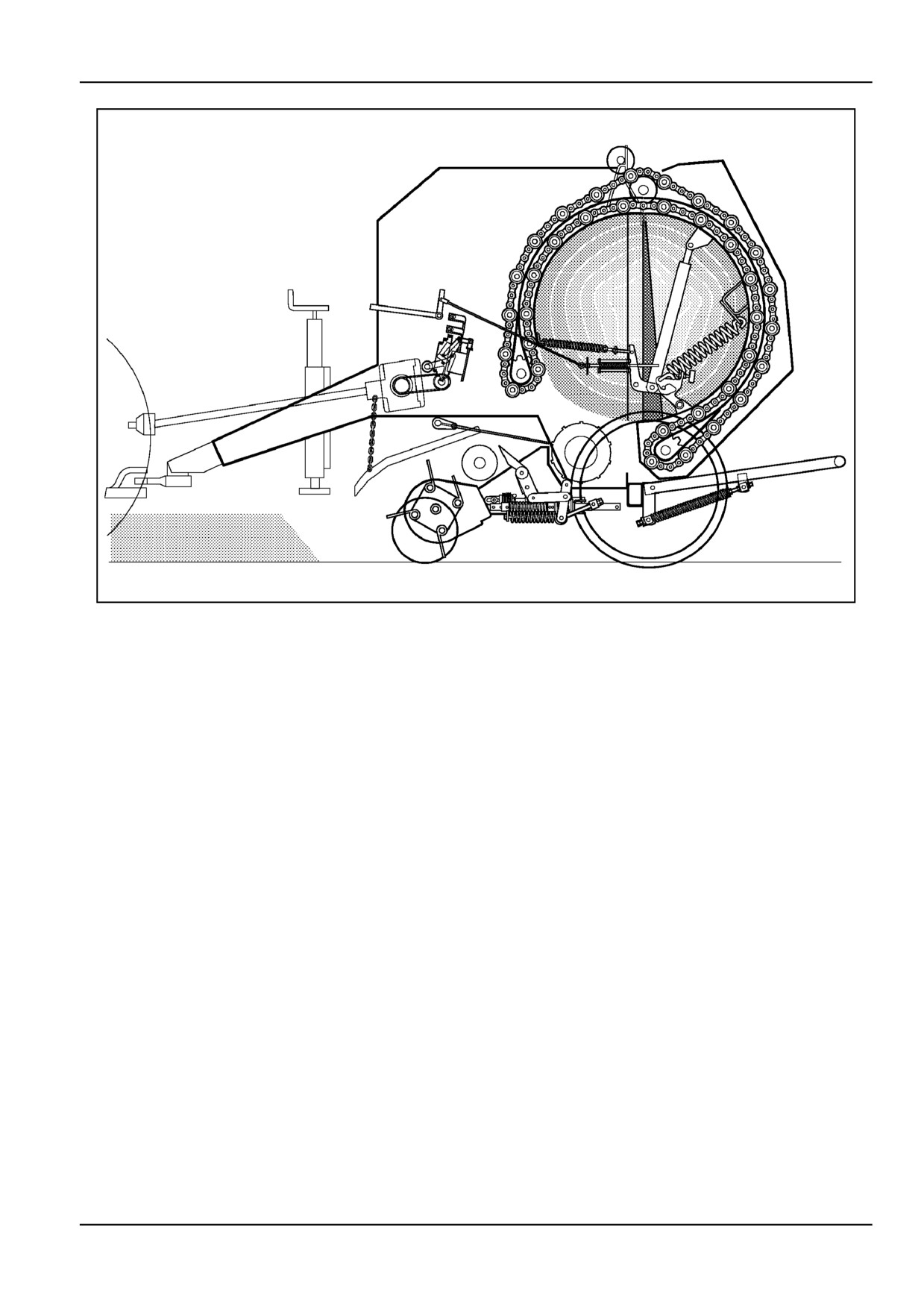
The bale has reached the desired density.
The twine wrap cycle is started manually, electrically
optional or mechanically. During standstill, the bale is
wrapped with twine.
At the wrap cycle start, the twines are ejected in the pickup
area and picked up between the rotating bale and the floor
roll. Twine spreaders will move back and forth to place the
different wraps on the bale. At the end of the wrap cycle,
the twines are cut and the wrapper components are in the
home position again. The bale is ready to be ejected.
1 - 11
1 - GENERAL INFORMATION
ZIL10FCRB044FAA
6
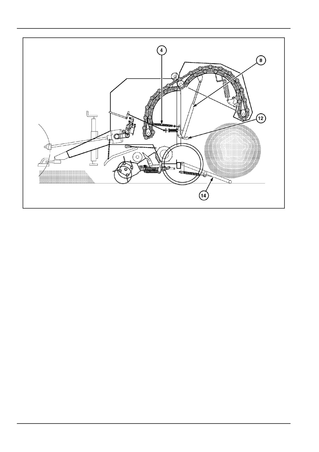
The bale is wrapped and ready to be ejected. The opera-
The operator closes the tailgate by means of the tractor
tor opens the tailgate by means of the tractor hydraulics.
hydraulics, the tailgate comes down by its own weight.
When the tailgate is closed, the latch spring (4) reengages
During bale ejection, the PTO. remains engaged.
the latch (12). The density indicators drop down to 0 den-
sity to confirm the tailgate is closed and latched.
The extending tailgate cylinder (8) first releases the tail-
gate latch (12) then lifts the tailgate. The density indica-
The operator must hold and lock the tractor valve lever
tors shoot up to "full bale density" as the tailgate opens.
in the "lower" position:
•
in the "lower" position in the case of a single-acting
The bale rolls out of the bale chamber, over the bale ejec-
valve
tor (14) optional, clear of the baler. With the bale ejector,
the bale can be ejected and the tailgate closed without
•
or the "float" position in case of a double-acting
moving the baler back and forth on flat ground.
valve,
On machines without bale ejector, the operator first has
for the tailgate to close, for the latch to engage and for the
to reverse a few meters before ejecting the bale. Then,
tailgate cylinder to float.
after the bale has been ejected, he has to move forward
again before closing the tailgate.
The baler is now ready to start the next bale.
1 - 12
1 - GENERAL INFORMATION
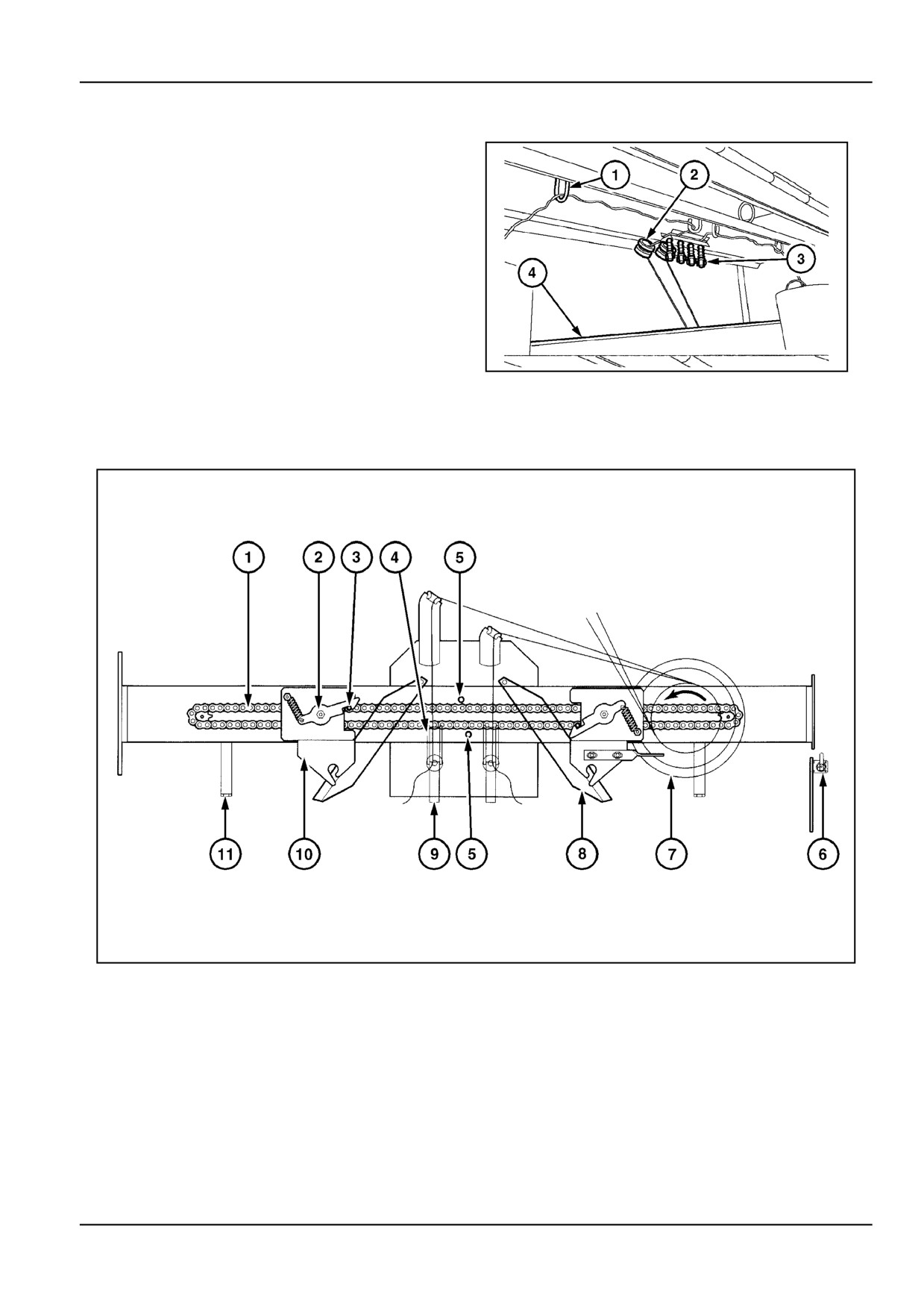
Twine Wrapper [25663647]
Twine wrapper mechanism components
The twine wrapper is mounted above the pickup, with the
twine being pulled into the chamber by the crop. When
the bale density indicators in front of the machine show
the required bale density, the operator starts the twine
wrapping cycle, manually or electrically (option).
The twine wrapper mechanism consists of the following
components in the twine box compartment
1.
Metal twine guides
2.
Porcelain twine guides
3.
Twine tensioner
ZIL10FCRB746AAA
1
4.
Twine box
Twine wrapper unit
ZIL10FCRB045FAA
2
1. Spreader drive chain
7. Twine pattern pulley
2. Pawl hook
8. Twine knives
3. Chain pawl
9. Feed Roll
4. Upper feeder roll
10. Twine spreader
5. Fixed pawl
11. Twine stop
6. Bale counter
1 - 13
1 - GENERAL INFORMATION
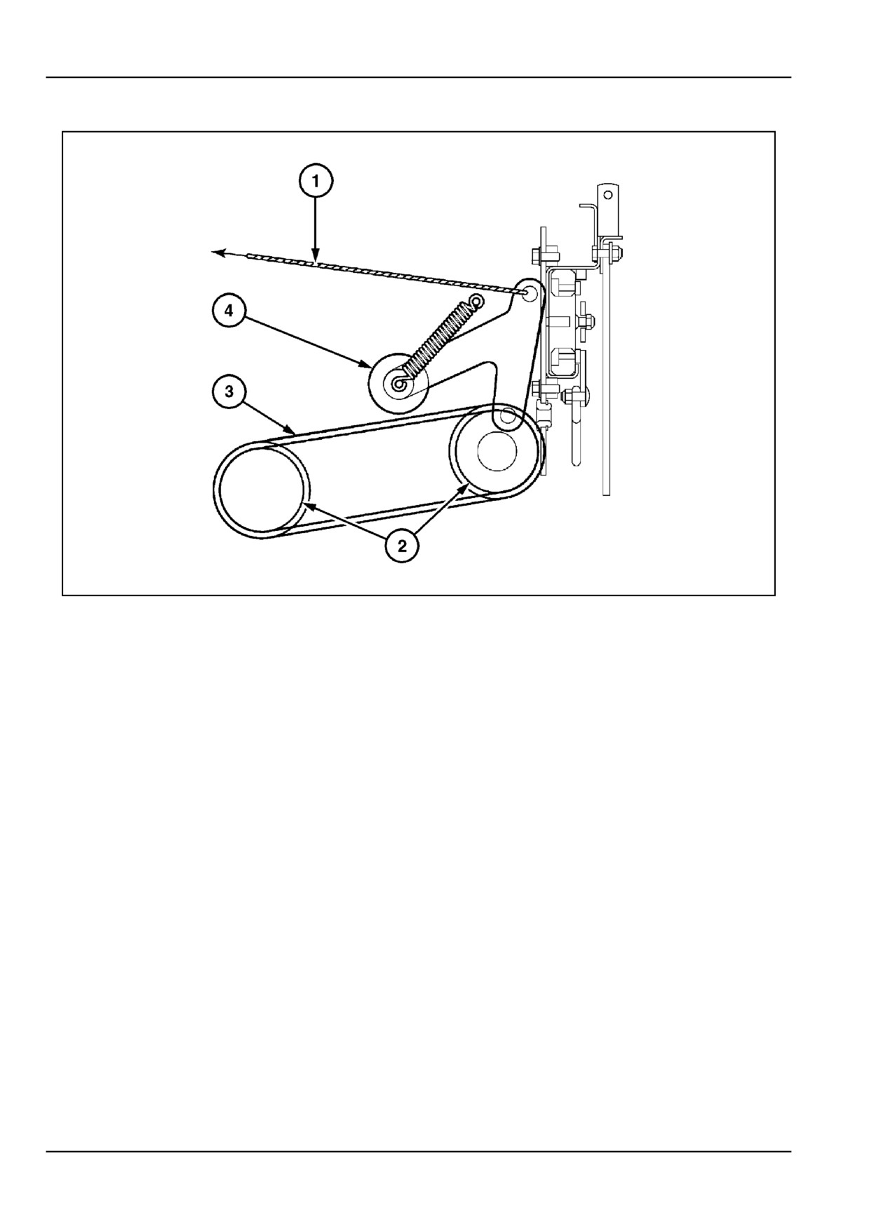
Twine start mechanism
ZIL10FCRB052FAA
3
1. Twine starting cord (standard)
4. Belt tensioner
2. Drive pulleys
5. Twine actuator (option)
3. Drive belt
6. Actuator spring
1 - 14
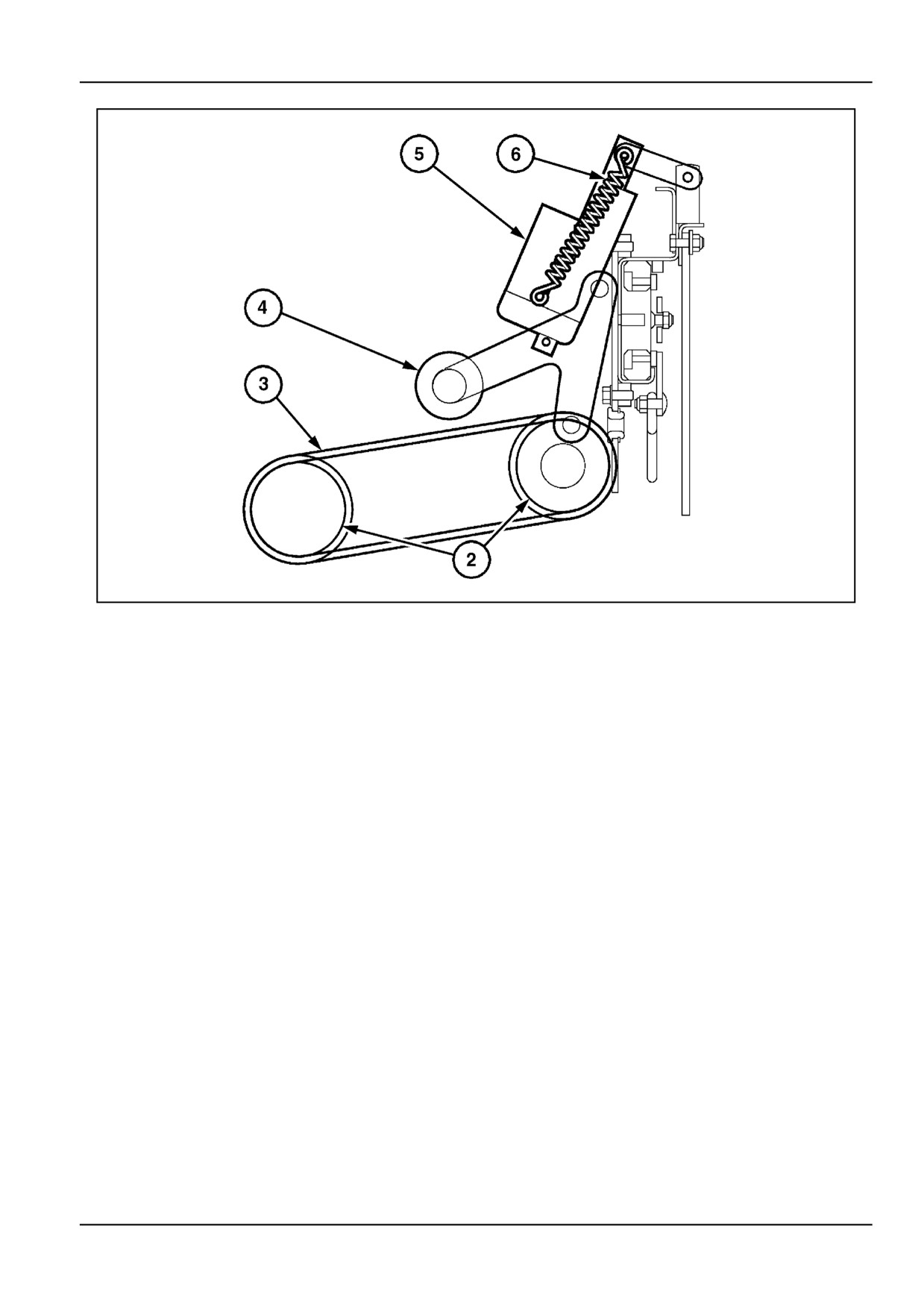
1 - GENERAL INFORMATION
ZIL10FCRB053FAA
4
1. Twine starting cord (standard)
4. Belt tensioner
2. Drive pulleys
5. Twine actuator (option)
3. Drive belt
6. Actuator spring
1 - 15
1 - GENERAL INFORMATION
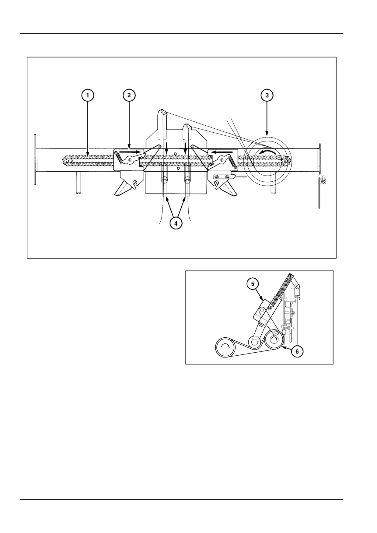
How the twine wrapper functions
ZIL10FCRB046FAA
5
With reference to Figure 2 and Figure 3:
A bale is being formed in the bale chamber. The wrapper
components are in the home position. When the bale
reaches the desired density, the operator extends the
electric actuator (5) or pulls the starting cord (1) in Figure
3 on 1-13, which will tension the drive belt (6) through the
belt tensioner. As a result of this, the twine feed rolls (4)
eject the twines in the pickup area.
Once the twine is picked up by the bale, the operator re-
leases the twine start button on the electric control box,
and the actuator will retract automatically. In the other
case, the operator releases the twine starting cord to take
ZIL10FCRB725AAA
6
tension off the drive belt.
Now the twine drives the feed rolls and the pattern pulley
(3), which in turn will drive the spreader chain (1) and
spreaders (2). The twines dwell in the middle of the bale
to lay the starting wraps.
1 - 16
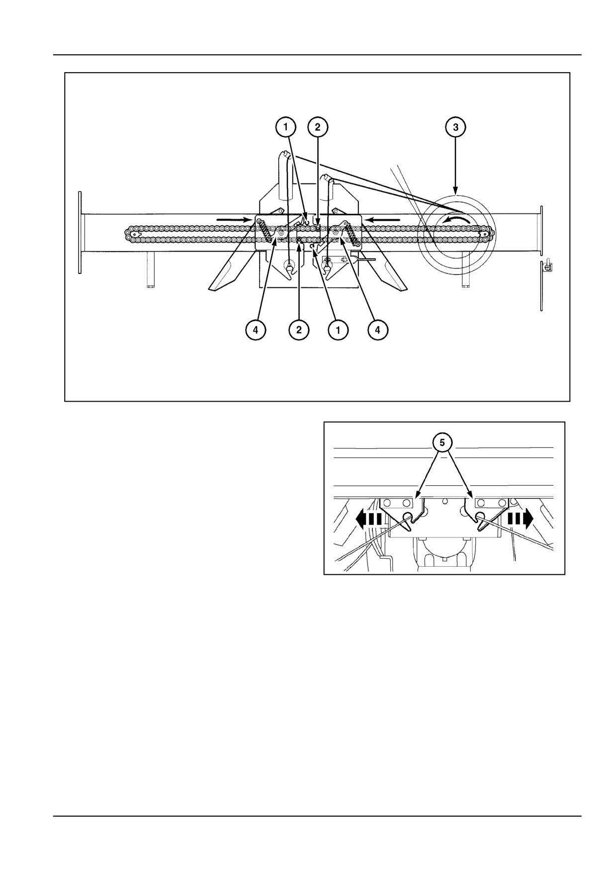
1 - GENERAL INFORMATION
ZIL10FCRB047FAA
7
With reference to Figure 4 and Figure 8:
The twines drive the pattern pulley (3). Thereby, the
spreaders (5), attached to the chain pawls (2) by means
of the pawl hooks (4), will move to the middle to pick up
the twine. At this point, the spreaders change direction.
To obtain this, the fixed pawls (1) will disengage the
spring-loaded pawl hooks from the chain pawls as they
pass by.
The chain pawl that pulled and then released the left
spreader hook, will now push the right spreader hook to
move it to the outside. The chain pawl that pulled and
then released the right twine spreader will push the left
ZIL10FCRB747AAA
8
spreader to move it to the outside.
View from the inside of the bale chamber
1 - 17
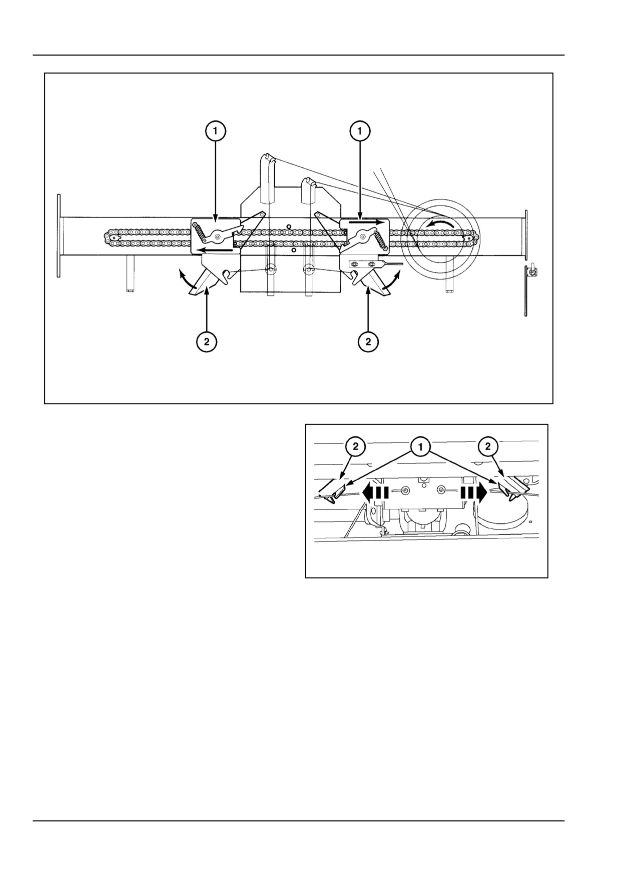
1 - GENERAL INFORMATION
ZIL10FCRB048FAA
9
With reference to Figure 9 and Figure 10:
Once they have picked up the twine, the spreaders (1)
move to the outside of the bale in a continuous way. The
running twines will approach the knives (2) from the flat
side. As the spreaders pass by, the knives will be lifted by
the twine tension, without cutting the twines.
ZIL10FCRB748AAA
10
View from the inside of the bale chamber
1 - 18
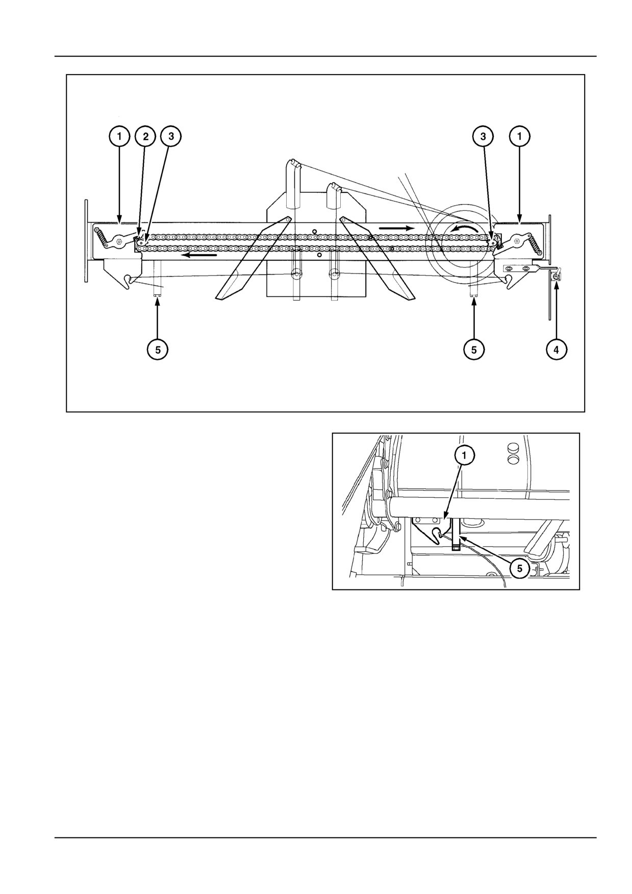
1 - GENERAL INFORMATION
ZIL10FCRB049FAA
11
With reference to Figure 11 and Figure 12:
As the twine spreaders (1) reach the bale edges, the
twines will be guided by the twine stops (5) to lay the end
wraps on the bale.
Here again, the spreaders change direction. As the
chain pawls (2) pass over the sprockets (3), they change
from pushing the spreaders to the outside, to pulling the
spreaders by engaging in the pawl hooks. This will move
the spreaders back to the middle.
Meanwhile, the right spreader will activate the mechanical
bale counter (4) to increase the bale count by one.
ZIL10FCRB749AAA
12
View from the inside of the bale chamber
1 - 19
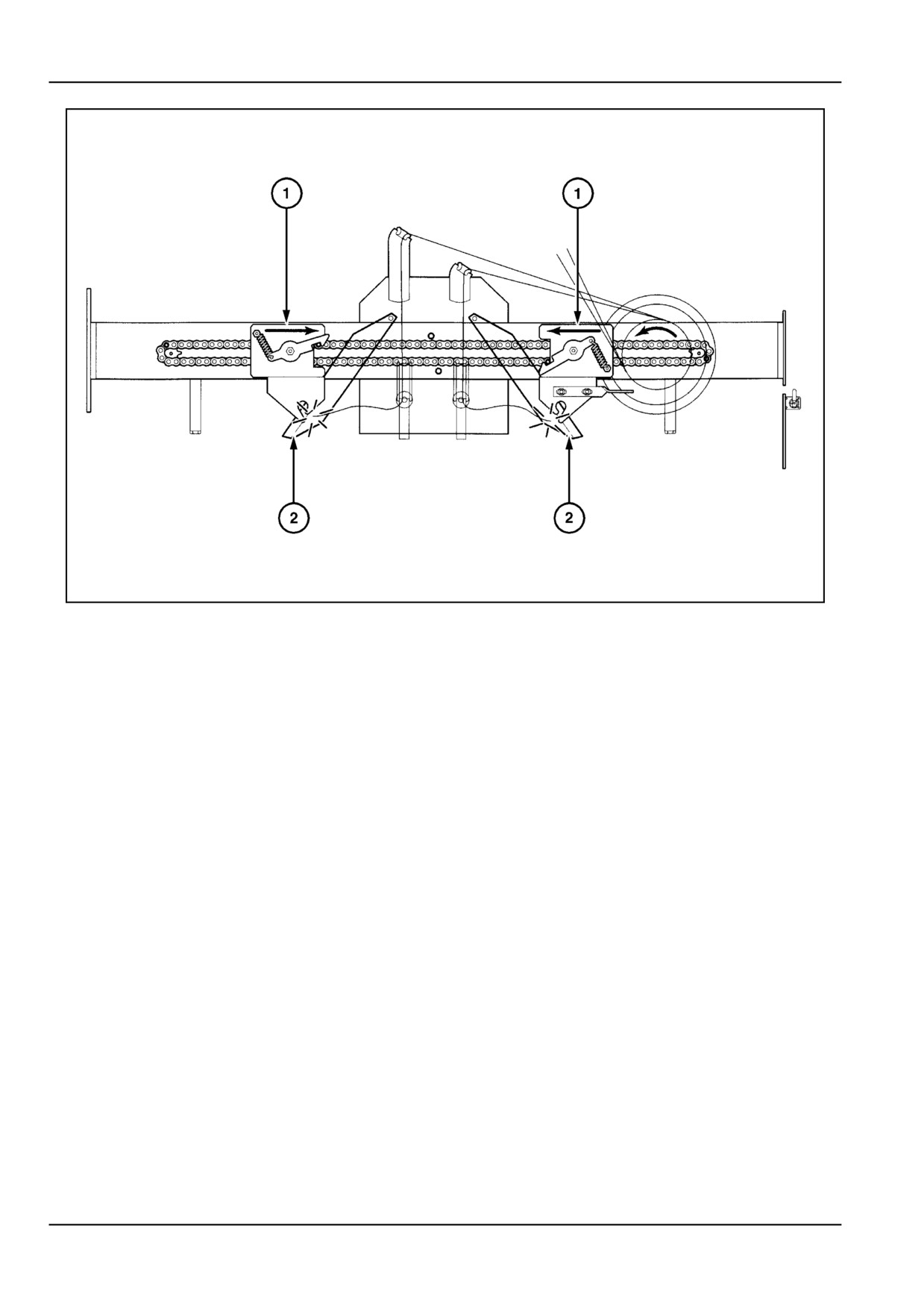
1 - GENERAL INFORMATION
ZIL10FCRB050FAA
13
With reference to Figure 13:
As the spreaders (1) move back to the middle, the running
twines will approach the knives (2) from the sharp side.
This will cut the twines as the spreaders pass in front of
the knives.
As the twines have been cut, the spreaders will stop mov-
ing. Now all wrapper components are in the home position
again, ready to start the next wrapping cycle.
The bale inside the bale chamber is ready to be ejected.
1 - 20
1 - GENERAL INFORMATION
Bale density system [25767091]
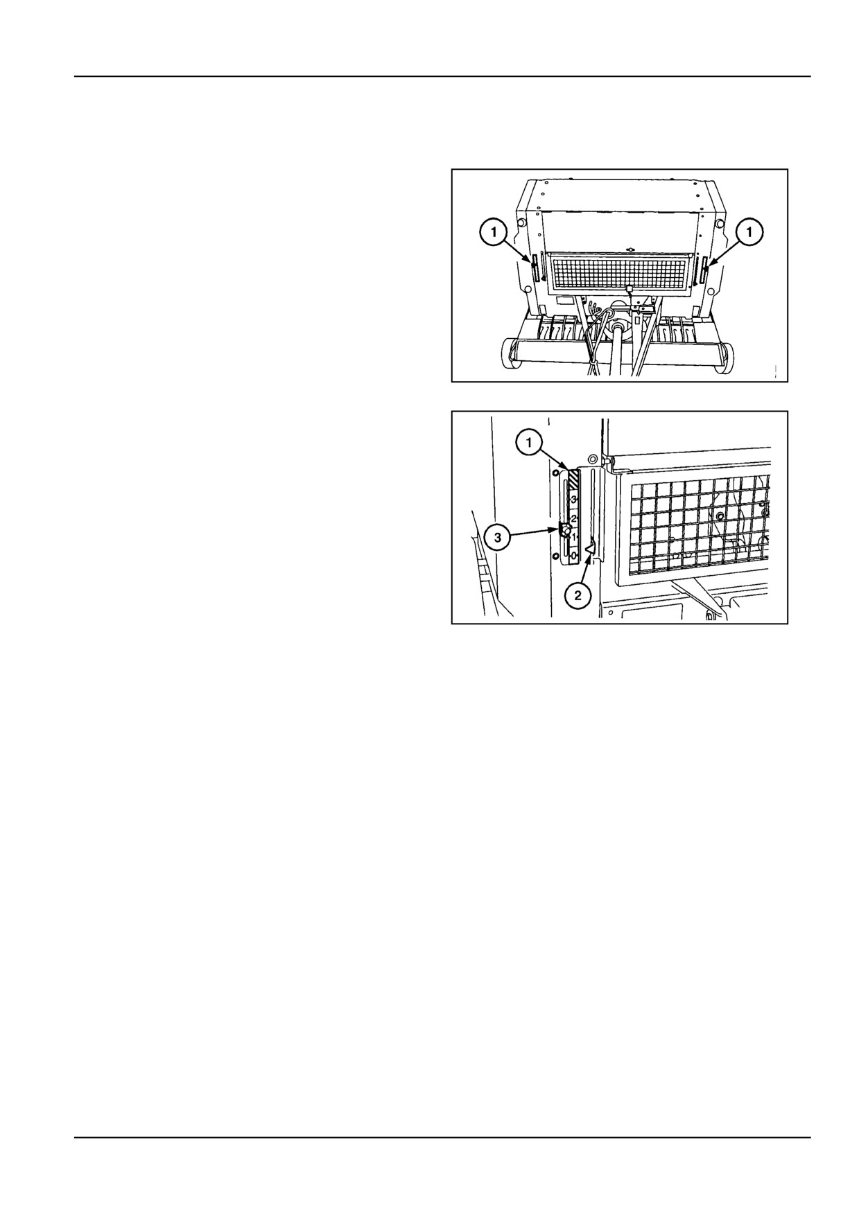
Bale density indicators
The mechanical bale density indicators (1) on the front left
and right of the machine serve several functions.
•
Tailgate open/closed, latched/unlatched.
•
Bale shape and density indication.
•
Full bale density indication.
ZIL10FCRB758AAA
1
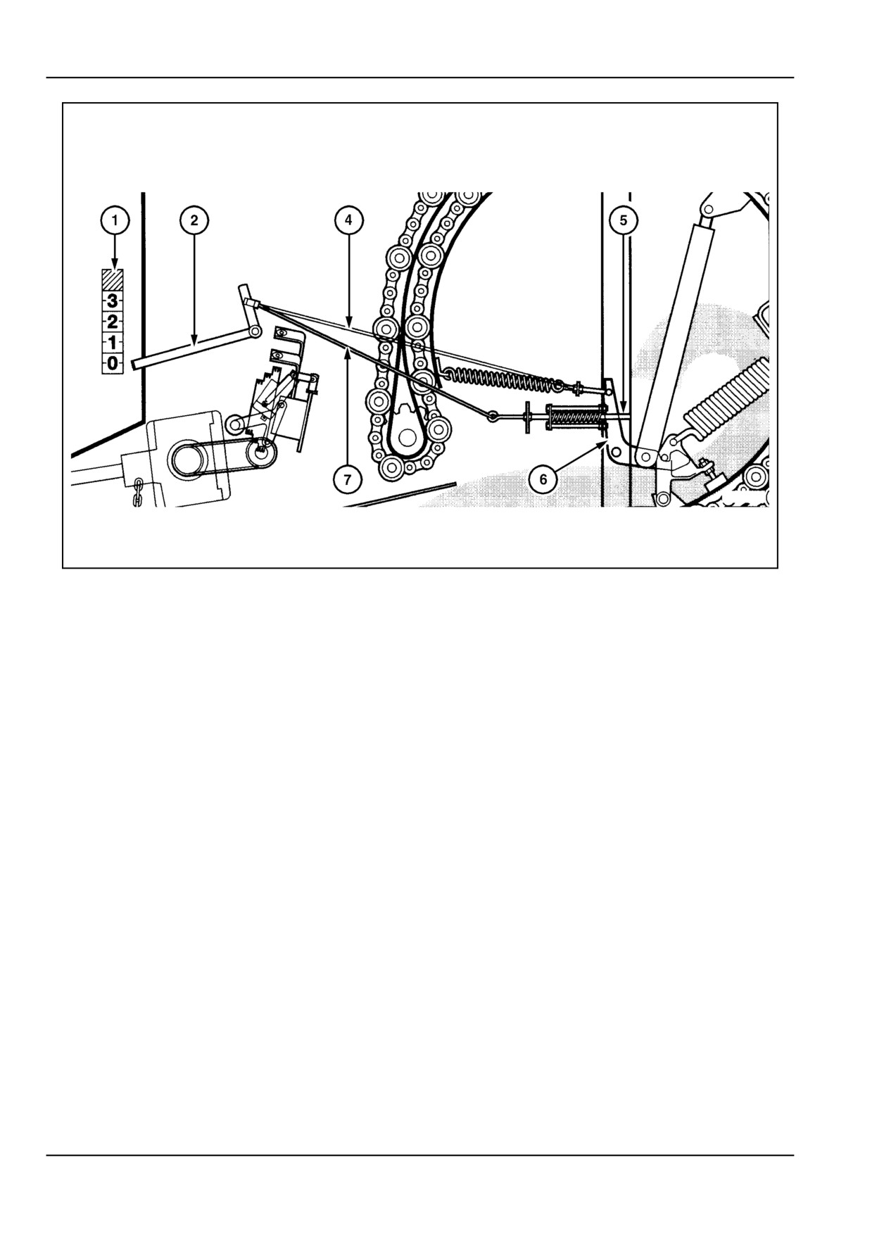
The bale density indicator system with reference to 2 and
3 consists of the following components:
1.
Density scale
2.
Indicator
3.
Full density pointer
4.
Tailgate latch cable
5.
Density feeler rod
6.
Tailgate latch
7.
Density cable
ZIL10FCRB759AAA
2
1 - 21
1 - GENERAL INFORMATION
ZIL10FCRB054FAA
3
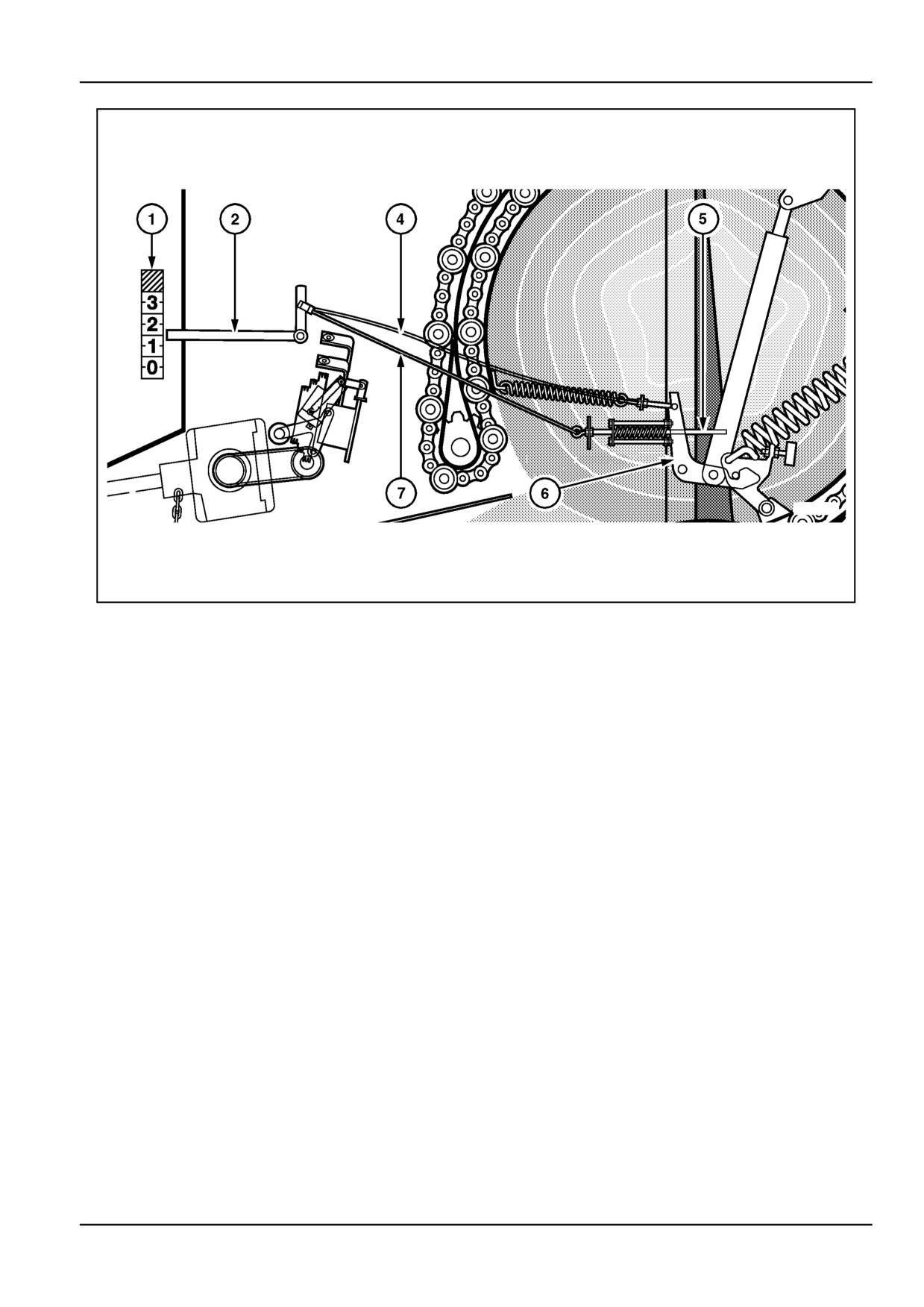
As long as the tailgate is closed and latched, the density
indicators (2) will point at zero density on the density scale
(1).
1 - 22
1 - GENERAL INFORMATION
ZIL10FCRB055FAA
4
With reference to Figure 4, once the bale chamber is filled
up and the tailgate starts opening under the bale pressure,
the spring-loaded density feeler rod (5) will move and stay
in contact with the opening tailgate. This will pull the den-
sity cable (7) and lift the indicator (2) gradually.
Now the operator should drive left/right over the windrow
to keep the left and right density indicators balanced and
produce an evenly shaped bale.
During bale formation, and with the tailgate latches (6) still
engaged, the tailgate latch cable (4) will slacken a little as
bale density increases.
When the density indicators reach the desired density,
which can be set with the density pointers (Figure 2) the
operator has to start the wrapping cycle.
NOTE: The bale density pointers only serve as a visual
reference to full bale density. They are not connected to
any alarm and/or flashing light. On machines equipped
with the electric control box (optional), the operator will
hear an audible alarm when full bale density is reached.
For more details, refer to the following paragraph.
1 - 23
1 - GENERAL INFORMATION
ZIL10FCRB056FAA
5
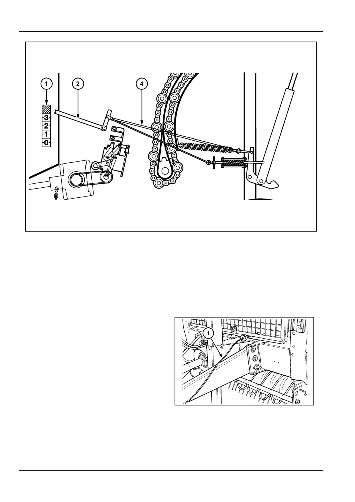
With reference to Figure 5, whenever the tailgate is
opened or unlatched, the tailgate latch cable (4) will pull
the density indicators (2) fully up in the screened area of
the density scale (1).
When the tailgate is closed and latched again (tailgate
latches pulled up completely), the density indicators fall
back to zero density.
Twine wrapper controls
Manual starting cord
The wrapping cycle is manually initiated using the starting
cord (1). When the bale reaches full density, the operator
pulls and holds the starting cord to tension the drive belt
of the twine feed rolls.
For more details, refer to twine wrap mechanism.
ZIL10FCRB829AAA
6
1 - 24
1 - GENERAL INFORMATION
Tractor Requirements [25762580]
Tractor Horse power requirements
The baler requires a tractor with an output, available at
the PTO to drive the baler:
Select a tractor with additional power for tractive effort in
accordance with terrain conditions (i.e. 10 kW (13.6 Hp)
on flat land or more as required on sloping land).
Minimum
Recommended
Model BR6080
37 kW (50.3 Hp)
52 kW (70.7 Hp)
Tractor wheel setting
As the tractor has to straddle the windrow, ensure the trac-
tor selected has adequate clearance under the frame to
avoid bunching of the material. If required, attach a can-
vas under the tractor body, rear axle and hitch to deflect
the crop down.
Adjust the tractor wheels for 140 - 160 cm (55.1 - 63.0 in)
clearance between the rear tires, if possible.
1 - 25
1 - GENERAL INFORMATION
Power take off (PTO) [25765238]
The PTO control on the tractor is used to start and stop
the baler. Less shock is transmitted to the driveline if the
tractor engine is set at a low to medium idle speed before
engagement. After the unit is running, adjust the tractor
throttle to deliver a full 540 RPM to the PTO
NOTICE: Never allow the PTO speed to exceed 540 RPM
or machine damage and short life may result.
Tailgate hydraulic control
The tractor hydraulic control is used to open and close the
tailgate on the baler. Refer to "Hydraulic outlets" for more
details on how to operate the tractor hydraulics to open
and close the tailgate.
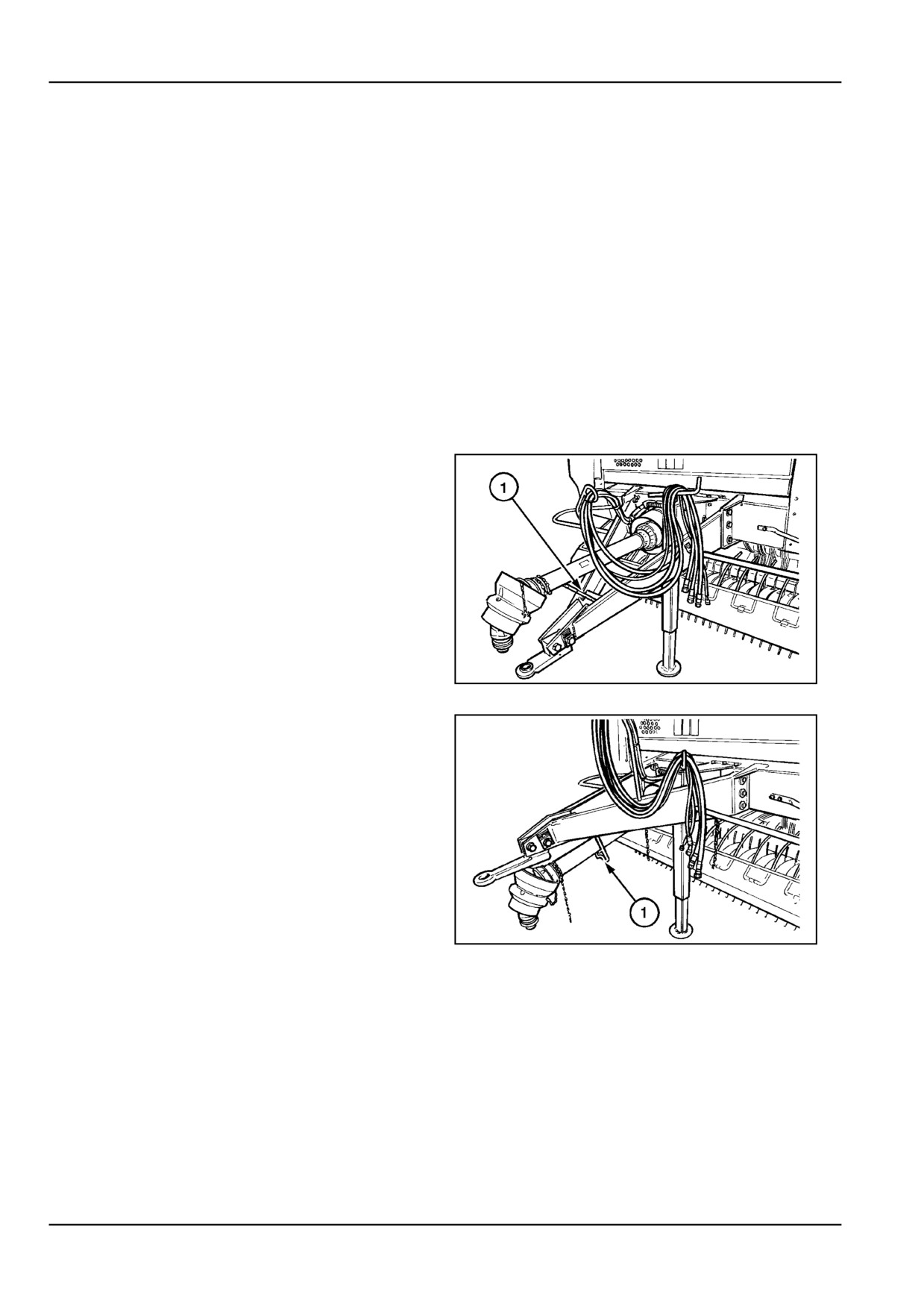
PTO support
When detaching the baler from the tractor, rest the PTO
onto the PTO support (1).
When the baler hitch is fitted in the high position, the PTO
hangs in the support (1).
When attaching the baler to the tractor, swing the support
rearward to a horizontal position.
ZIL10FCRB093AAA
1
NOTICE: To transport the baler, the PTO must be coupled
to the tractor, and the PTO support swung to its horizontal
position. Do not transport the baler with the PTO resting
on the support.
ZIL10FCRB063AAA
2
1 - 26
1 - GENERAL INFORMATION
Jack stand [25765689]
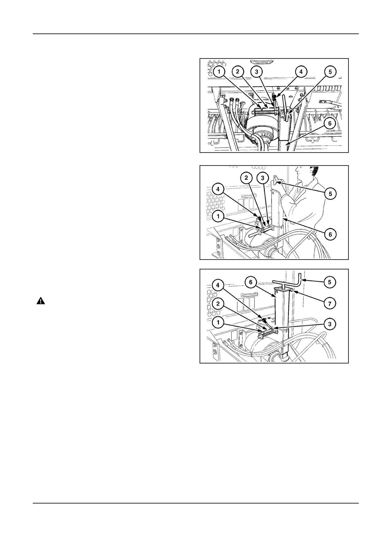
Winding the jack crank (5) will raise or lower the baler
tongue to attach/detach the baler from the tractor. The
complete jack stand (6) can be moved down to the storage
position, and moved up to the transport position. Grab
the jack at the crank (5) and/or the grab handle (7) Refer
Figure, 3.
ZIL10FCRB110AAA
1
The spring-loaded jack stand latch (4) has three positions
to be used:
•
Latch (4) engaged in notch (3) secures the jack
stand in either storage or transport position. Make
sure the latch is securely engaged in notch (3) at
all times in either the transport or storage position
of the jack. In the transport position, wind the crank
(5) to lift the jack fully up.
•
Latch (4) disengaged and riding along the edge (2)
allows the jack stand to be moved up or down. It
snaps engaged automatically when the desired po-
sition is reached.
ZIL10FCRB144AAA
2
•
Notch (1) allows the latch (4) to be mechanically
locked out temporarily during the manipulation
process, or permanently should special situations
require so.
WARNING
Crushing hazard!
Equipment could fall if not properly sup-
ported. Position suitable jack stands under
the feeder housing and secure in place before
servicing.
Failure to comply could result in death or se-
rious injury.
W0008B
ZIL10FCRB103AAA
3
ATTENTION: Be cautious when operating the jack stand.
There is risk of injury by pinching or shearing points. Grab
the jack crank with both hands as illustrated to lift and
lower the jack stand.
1 - 27
1 - GENERAL INFORMATION
Parking Brake [25765751]
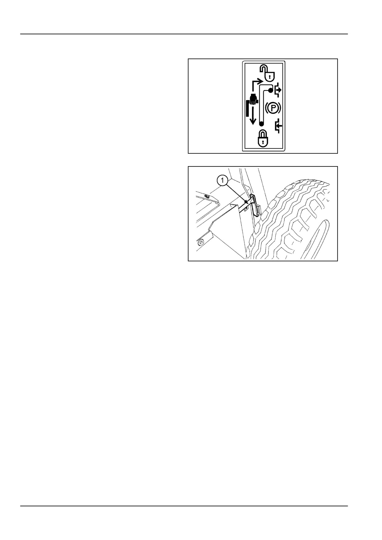
For some countries a wheel lock may be fitted to these
machines, and must be engaged when the machine is
parked.
An instruction decal is provided on the left hand side of
the machine above the wheel.
ZIL10FCRB161AAA
1
The lever (1) operates a wheel lock pin which engages in
the wheel hub, preventing the wheel from rotating.
NOTE: The wheel lock pin is disengaged when the lever
is in the position shown opposite, when towing the baler
behind the tractor.
When the tractor is parked engage the wheel lock by mov-
ing the lever (1) out and downwards.
ZIL10FCRB724AAA
2
1 - 28
2 - SAFETY INFORMATION
2 - SAFETY INFORMATION
Safety rules [25658997]
Farm accidents can be prevented with your help, no accident prevention programme can be successful without the
wholehearted cooperation of the person who is directly responsible for the operation of the equipment.
To read of accident reports from all over the world is to be convinced that a large number of accidents can be prevented
only by the operator anticipating the result before the accident is caused and doing something about it.
It is said that "The best kind of safety device is a careful operator who with care and mature consideration can save
more lives and limbs than any accident prevention programme which is not adhered to".
Safety statements
Throughout this manual and on machine decals, you will find precautionary statements ("CAUTION", "WARNING",
AND "DANGER") followed by specific instructions. These precautions are intended for the personal safety of you and
those working with you. Please take the time to read them.
CAUTION: The word "CAUTION" is used where a safe behavioral practice according to operating and maintenance
instructions and common safety practices will protect the operator and others from accident involvement.
WARNING: The word "WARNING" denotes a potential or hidden hazard which could possibly cause serious injury. It
is used to warn operators and others to exercise due care and attention to avoid a surprise accident with machinery.
DANGER: The word "DANGER" denotes a forbidden practice in connection with a serious hazard which could result
in death.
FAILURE TO FOLLOW THE "CAUTION", "WARNING", AND "DANGER" INSTRUCTIONS MAY RESULT IN SERI-
OUS BODILY INJURY OR DEATH.
Safety reminders
DANGER
Unexpected movement!
Make sure parking brake is applied. Secure machine with wheel chocks.
Failure to comply will result in death or serious injury.
D0013A
DANGER
Entanglement hazard!
Make sure the Power Take-Off (PTO) safety chain is properly hooked in position before operating the
machine.
Failure to comply will result in death or serious injury.
D0040A
DANGER
Crushing hazard!
Make sure the area surrounding the tailgate is clear of all persons and domestic animals before open-
ing or closing the tailgate.
Failure to comply will result in death or serious injury.
D0034A
DANGER
Crush hazard! The tailgate may close faster than you can move away.
ALWAYS make sure the tailgate lockout valves are in the OFF (locked) position before working under
a raised tailgate. In the event of a sudden loss of hydraulic pressure, the tailgate will fall if the lockout
valves are not engaged. Stand clear of the tailgate before disengaging the lockout valves.
Failure to comply will result in death or serious injury.
D0002A
2 - 1
2 - SAFETY INFORMATION
WARNING
Entanglement hazard!
Disengage the Power Take-Off (PTO), turn off the engine, and remove the key. Wait for all movement
to stop before leaving the operator's position. Never adjust, lubricate, clean, or unplug machine with
the engine running.
Failure to comply could result in death or serious injury.
W0227A
WARNING
Moving parts!
Make sure all entry and mechanical access doors are properly closed before operating the machine.
Failure to comply could result in death or serious injury.
W0238A
WARNING
Burn hazard!
Stop baling immediately if you notice a scorched odor, an unusual sound, or the sight of smoke or
flames. Do not attempt to extinguish a fire that is too far advanced.
Failure to comply could result in death or serious injury.
W0186A
WARNING
Fire hazard! Crop materials are flammable and present a high risk of fire.
Frequently remove accumulated crop or wrapping material from the machine. Inspect the machine
for oil leaks and overheated bearings or other moving parts. Immediately service the machine when
required; DO NOT continue to use machine until service is complete.
Failure to comply could result in death or serious injury.
W0392A
WARNING
Personal Protective Equipment (PPE) required.
When assembling, operating, or servicing the machine, wear protective clothing and PPE necessary
for the particular procedure. Some PPE that may be necessary includes protective shoes, eye and/or
face protection, hard hat, heavy gloves, filter mask, and hearing protection.
Failure to comply could result in death or serious injury.
W0353A
WARNING
Pressurized fluid can penetrate the skin and cause severe injuries.
Keep hands and body away from any pressurized leak. DO NOT use your hand to check for leaks. Use
a piece of cardboard or paper. If fluid penetrates the skin, seek medical attention immediately.
Failure to comply could result in death or serious injury.
W0158A
WARNING
Crushing hazard!
Use caution when backing the towing unit up to the hitch. Have all persons in clear view before you
start to back up. Always take the towing unit out of gear and set the parking brake before anyone goes
behind the towing unit to check the hitch alignment.
Failure to comply could result in death or serious injury.
W0961A
Machine safety
Additional precautionary statements (ATTENTION, NOTE, and NOTICE) are followed by specific instructions. These
statements are also intended for your safety and avoidance of machine damage.
2 - 2
2 - SAFETY INFORMATION
General recommendations
•
Your round baler was designed with safety very
much in mind. However, there is no real substitute
for caution and attention in preventing accidents.
Once an accident has happened it is too late to
think about what you should have done!
•
Remember that the machine has been designed ex-
clusively for agricultural use. Any other application
must first be authorised by the manufacturer.
•
Read this manual thoroughly before starting off, op-
erating, servicing or carrying out any other operation
on the machine. A few minutes reading will save you
time and hassle later.
•
Read all the safety decals adhered to the machine
and follow the instructions. Immediately replace any
decals that are missing or damaged. Place orders
for these with your local dealer.
•
The machine should only be operated, maintained
and repaired by responsible persons instructed on
how to operate the machine and authorised to do
so.
•
Always keep a first aid kit handy.
•
Do not work around the machine wearing loose gar-
ments that could get caught in any of the moving
parts.
•
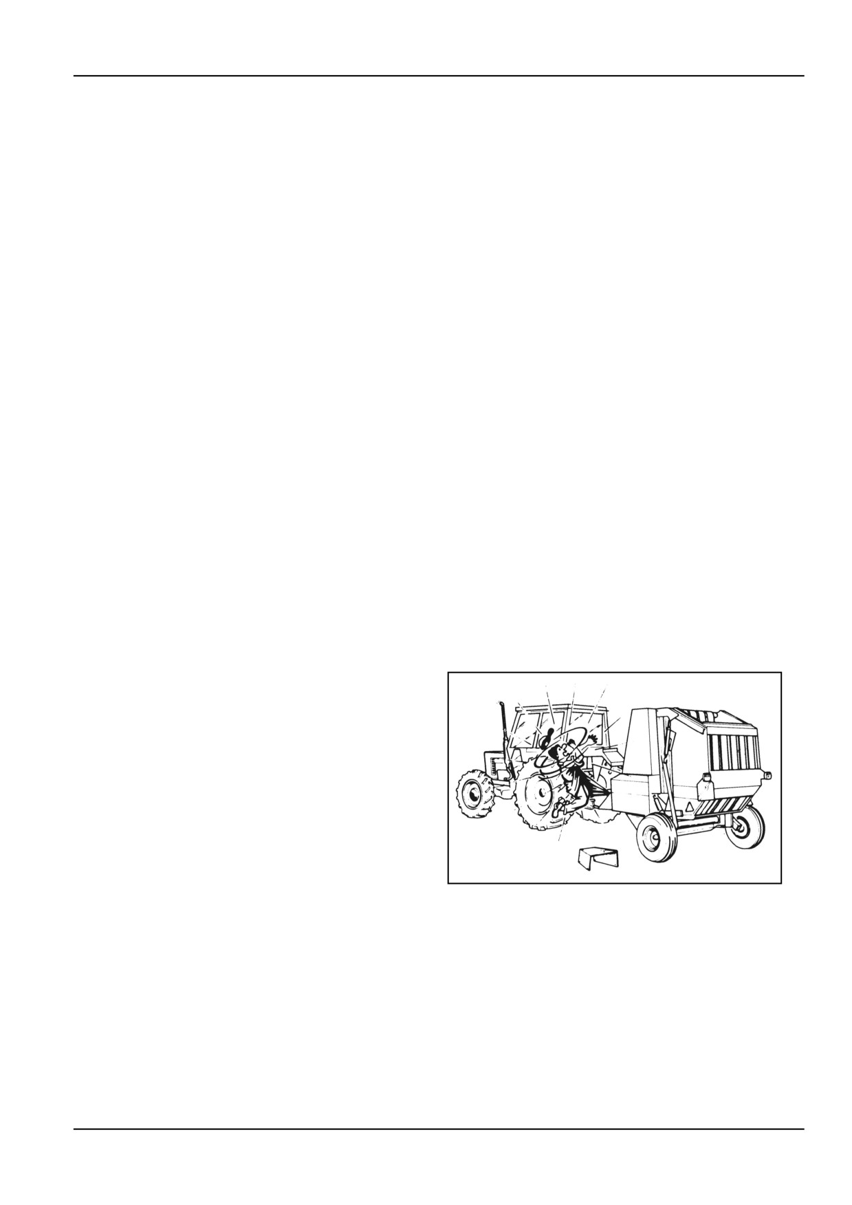
Keep persons clear of the area between tractor and
implement if the baler is not secured against unin-
tentional movement.
•
Use wheel chocks to immobilize the implement
when parking. They are delivered with the baler.
•
Check that all rotating parts connected to the PTO.
shaft are properly guarded.
ZIL10FCRB732AAA
1
•
Avoid using the machine in unsuitable crop and
weather conditions. It is better to stop work tem-
porarily rather than operating in such conditions.
•
Check that all guards and covers provided are prop-
erly fitted and secured.
•
It is highly recommended to equip the machine with
a fire extinguisher that should be located in an ac-
cessible location. Remember that a fire extinguisher
must be checked regularly and refilled or replaced
when necessary.
2 - 3
2 - SAFETY INFORMATION
Preparing for operation
•
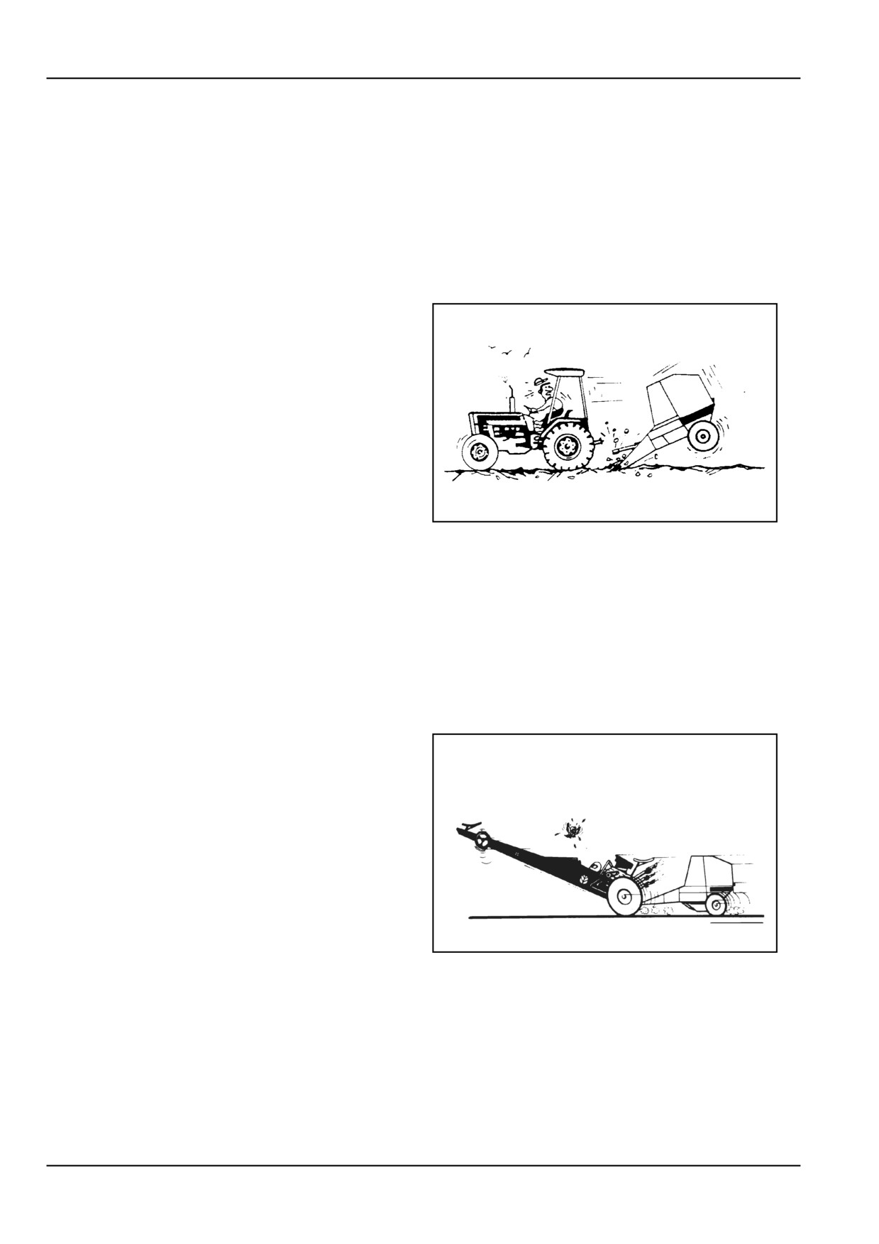
Before attaching the machine to the tractor, ensure
that the tractor is in good working order and that the
brakes are efficient, particularly if operating on hilly
ground. Also, ensure that the hydraulic system is
compatible with that of the baler.
•
Ensure that the PTO. lock pin is properly engaged in
the tractor power takeoff shaft. An incorrectly locked
PTO. shaft could work loose and cause accidents or
damage to the machine.
•
Make sure that the tractor drawbar hitch pin is not
worn and that it is securely locked to prevent the pin
from bouncing out.
ZIL10FCRB742AAA
2
•
Check that the electrical system is working correctly,
as well as the direction indicator lights.
Travelling on public roads
•
Before transporting the baler on public roads, raise
and mechanically secure the pickup in the highest
position, per instructions in this manual.
•
Ensure that tires are in good condition and properly
inflated.
•
Keep the towing speed down to 30 km/h (unless
local speed regulations restrict to a lower speed).
ZIL10FCRB735AAA
3
2 - 4
//////////////////////////////////////////