New Holland BR6080. OPERATOR’S MANUAL (2011) - page 2
2 - SAFETY INFORMATION
•
Use flashing beacons and/or reflector signs on the
machine and/or the tractor when travelling on public
roads to indicate the vehicle is slow-moving and thus
prevent accidents. Check local regulations.
•
Ensure the machine is equipped with all obligatory
lighting before driving on public roads and they are
functioning correctly.
•
When manoeuvring the baler, always be conscious
of its size.
•
Avoid taking corners at high speed.
•
Never travel at speed in crowded areas.
•
Always observe road regulations.
•
Do not carry a bale nor crop in the bale chamber
when travelling on the road.
•
Do not tow the machine with the tailgate open.
Operating the baler
WARNING: Before any person/s operate the baler ensure
they have the ability to operate machinery, and have been
specifically trained to operate the baler.
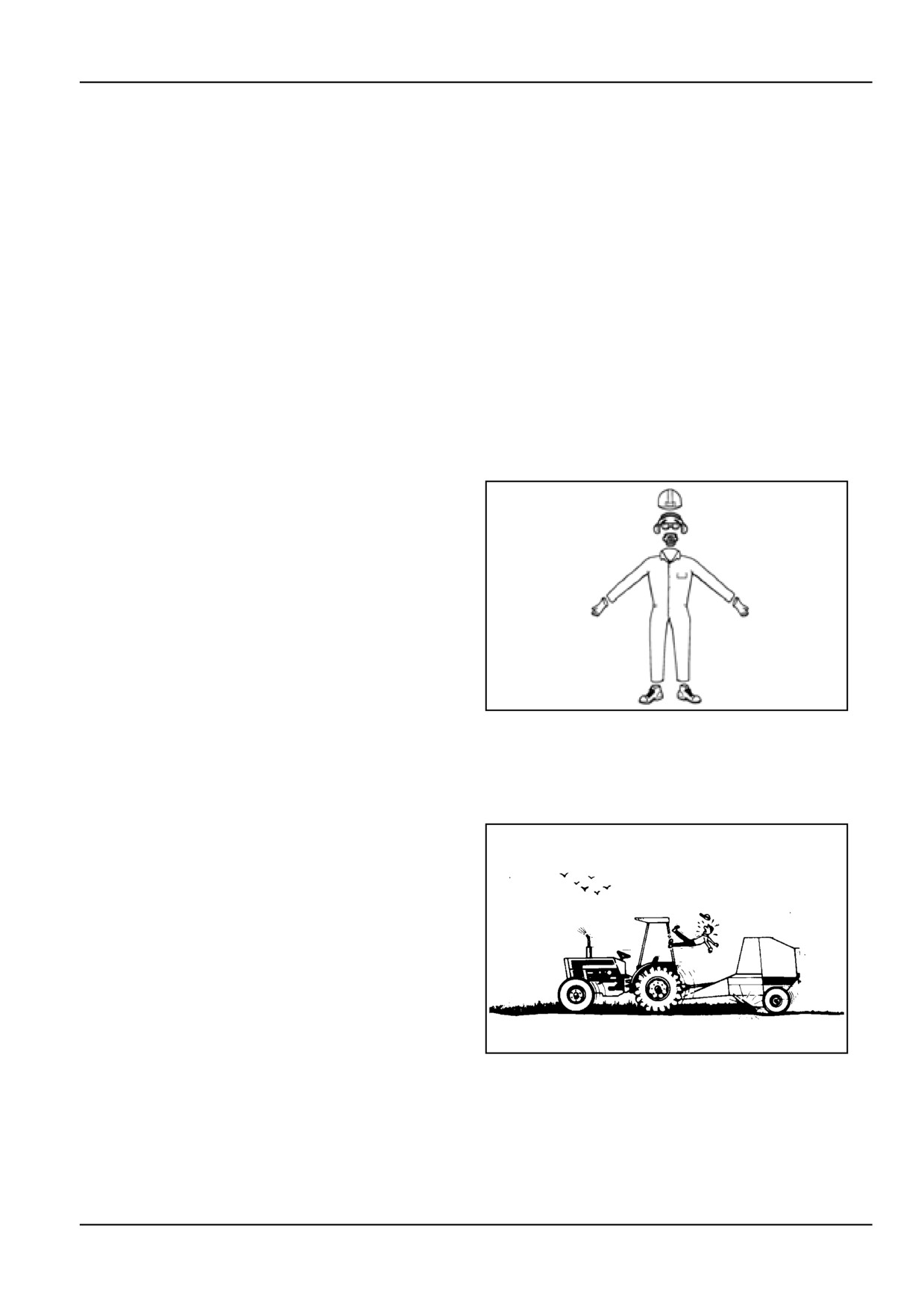
NOTICE: Wear suitable personal protective equipment
(PPE) and clothing to suit the conditions, and regulations
in your country. This equates but not limited to protection
of eyes, lungs, ears, head, hands and feet when oper-
ating, servicing or repairing the equipment. Always keep
hands, feet, hair and clothing away from moving parts. Do
not wear loose clothing, jewelry or other items that could
entangle with levers and/or linkages.
ZIL10FCRB843AAA
4
•
Before operating the machine ensure that all safety
guards are installed. Ensure all PTO. guards are
correctly installed and are restrained with all chains
provided.
•
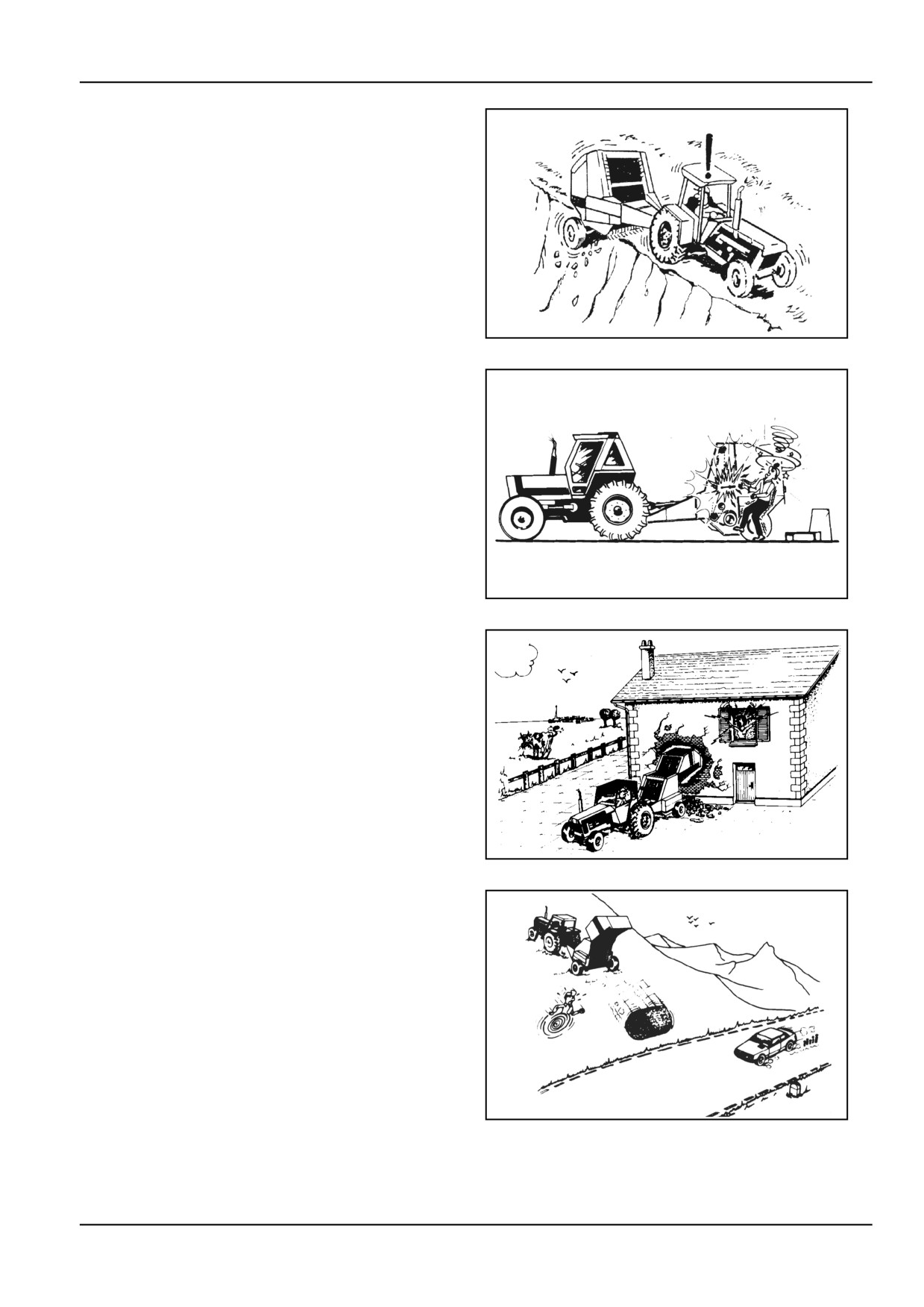
Do not attempt to operate or manoeuvre the baler,
unless sitting in the tractor seat.
ZIL10FCRB733AAA
5
2 - 5

2 - SAFETY INFORMATION
•
Never allow anyone to ride on the machine or the
tractor.
ZIL10FCRB734AAA
6
•
Always stop the tractor engine and wait until the ma-
chine has stopped completely before attempting to
clean, lubricate or carry out adjustments. To pre-
vent accidental starting of the machine, disengage
the PTO. drive, remove the tractor ignition key and
apply the handbrake before getting off the tractor.
Turn the power off on control instruments in the trac-
tor affecting the baler operation.
•
Do not enter the area between the tractor wheels
and the machine when the tractor engine is running.
•
Never attempt to clear crop or other foreign matter
from the pickup or other parts of the machine whilst
the machine is running. Such an imprudence could
cost you your life or limb. In the event of a blockage,
always disengage the PTO, switch off the tractor
engine and apply the handbrake first.
Typical hazard areas are the driveline, the pickup,
the bale chamber bar and chain conveyor, and the
twine and roll wrapper mechanisms.
•
When towing a loaded machine in the field or on
farm roads, keep the towing speed down to 10 km/h.
•
Before transporting the machine, raise the pickup
to the high position and support it mechanically per
instructions in this manual.
•
Do not make tight turns with the PTO. under a heavy
load to avoid damaging the PTO. joints and trans-
mission shaft.
•
Avoid taking corners at high speed.
•
Always operate the baler at safe speed in accor-
dance with the type of ground. On uneven ground,
proceed with the utmost caution to ensure proper
stability.
•
When operating on gradients do not drive too fast,
especially when turning.
2 - 6
2 - SAFETY INFORMATION
•
Use extreme caution when operating with the
wheels close to the edge of a ditch or a steeply
dropping embankment.
ZIL10FCRB743AAA
7
•
Keep hands, feet and/or garments away from mov-
ing parts.
Check that all transmission parts are correctly
guarded.
ZIL10FCRB737AAA
8
•
Never travel at speed in crowded areas.
•
Always remove the ignition key from the tractor
when leaving it unattended.
•
Always make sure that the area behind the machine
is clear before opening the tailgate.
ZIL10FCRB736AAA
9
•
Make sure that the baler is in good working condition
and regularly maintained.
•
Never unload or store bales where they could roll
down a slope.
•
If the bale starts rolling downhill, do not try to stop it.
•
Never work with a tractor equipped with a front
loader which is not fitted with safety grapple. Such
a grapple is designed to prevent the bale from run-
ning down the loader lift arms and falling onto the
operator. If using a front loader, always keep the
load close to the ground to prevent tractor instability.
ZIL10FCRB738AAA
10
2 - 7
2 - SAFETY INFORMATION
Angle of operation
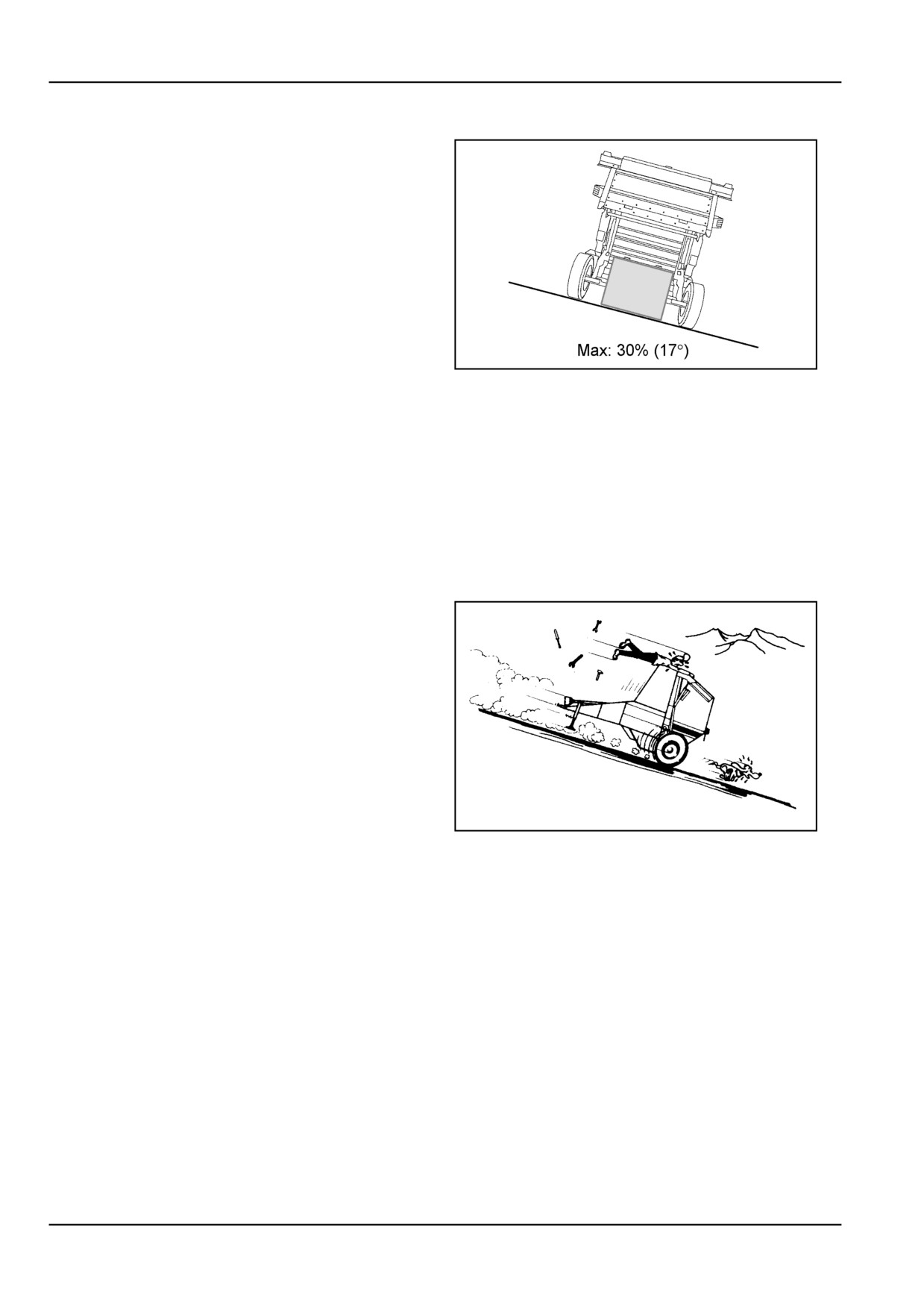
The baler must only be used by a skilled operator familiar
with all the controls and harvesting techniques on culti-
vated land. The baler should not be operated on inclines
exceeding 30 % 17 °.
WARNING: Round bales are heavy and may roll on in-
clines, do not try to stop a rolling bale.
ZIL10FCRB837AAA
11
Baler maintenance
•
Follow the maintenance schedule with regard to the
machine servicing intervals. Remember that the
machine requires attention from time to time. Also
remember that the time taken on maintenance will
greatly extend the life of your machine.
•
Replace stiff or worn bearings before they fail. Keep
the conveyor bars straight at all times. Replace or
straighten bent bars immediately.
•
Always chock wheels when parking the baler and
before working on or under the machine.
ZIL10FCRB740AAA
12
•
When working on the hydraulic system, always en-
sure that the system is not under pressure before
disconnecting pipes and/or hoses.
•
Whenever working on the machine with the tailgate
open, always engage the tailgate lock-out valve
lever.
•
Oil escaping under pressure could cause serious in-
jury. When tracing oil leaks, always protect your-
self from accidents by wearing shields, goggles and
gloves.
•
To protect the alternator and the battery of the trac-
tor, always detach the baler from the tractor before
carrying out any welding work on the machine or
working on electrical components.
2 - 8
2 - SAFETY INFORMATION
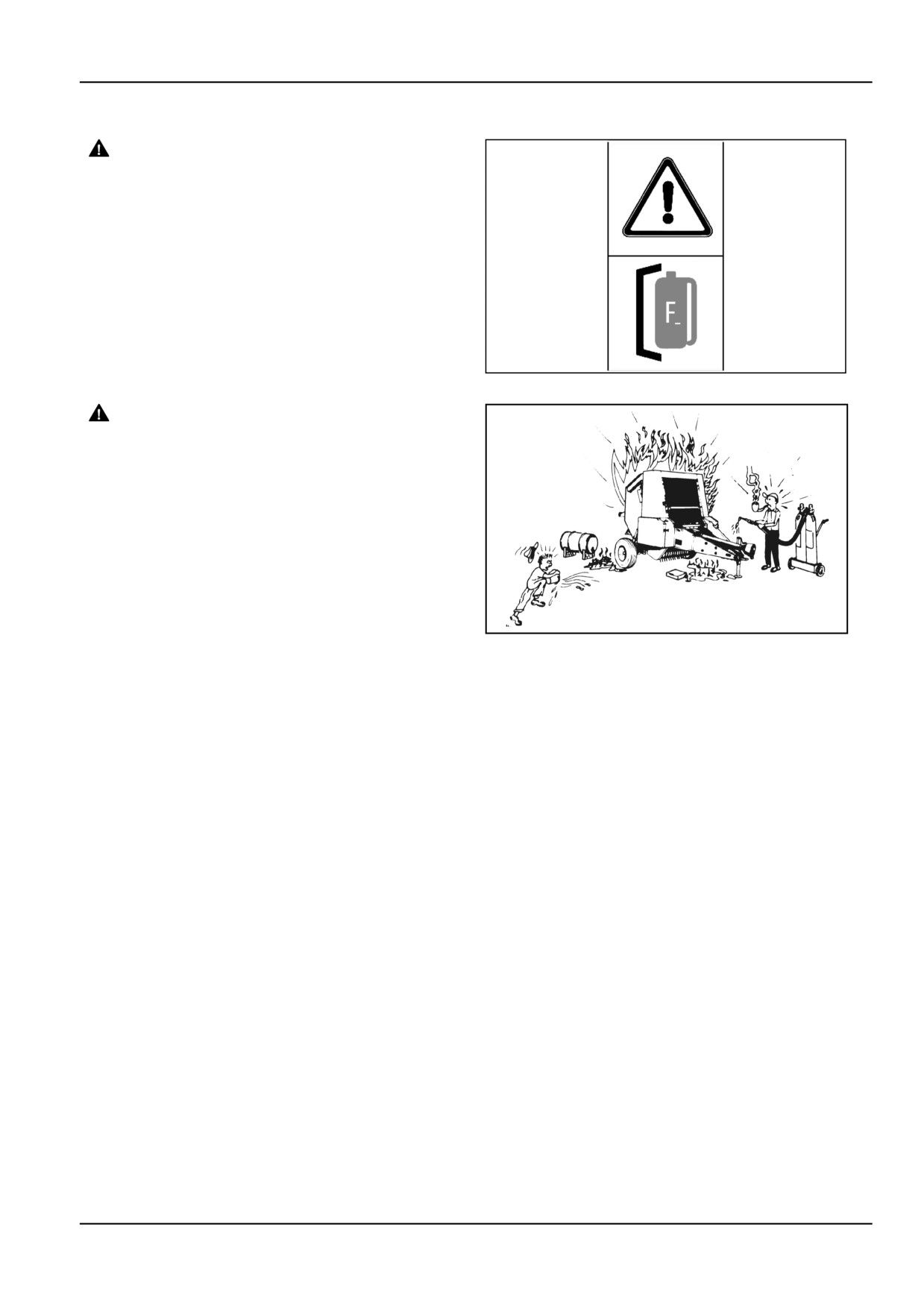
Fire extinguisher
DANGER
Fire hazard!
Always have a fire extinguisher on or near
the machine. Keep the fire extinguisher in
good condition through routine maintenance
and service according to the manufacturer's
instructions.
Failure to comply will result in death or serious
injury.
D0006A
ATTENTION: Avoid a fire hazard by keeping the machine
perfectly clean. Cleaning of chains and rollers must be
performed at least once a day or after each period of use.
FIRE
13
WARNING
Fire hazard! Crop materials are flammable and
present a high risk of fire.
Frequently remove accumulated crop or wrap-
ping material from the machine. Inspect the
machine for oil leaks and overheated bearings
or other moving parts. Immediately service
the machine when required; DO NOT continue
to use machine until service is complete.
Failure to comply could result in death or se-
rious injury.
W0392A
ZIL10FCRB741AAA
14
Should a fire occur, then first observe your personal safety
and that of other people. Only if it is safe to do so, try to
extinguish the fire.
Proceed as follows:
1.
Move tractor and baler upwind as far as possible
from flammable material.
2.
Eject the bale immediately, making sure the bale will
not roll away.
3.
Close the tailgate. Never stand under the raised
tailgate, even not when it is locked with the tailgate
lock-out valve.
4.
Use the fire extinguisher or pressurized water sup-
ply to put out any fire.
2 - 9
2 - SAFETY INFORMATION
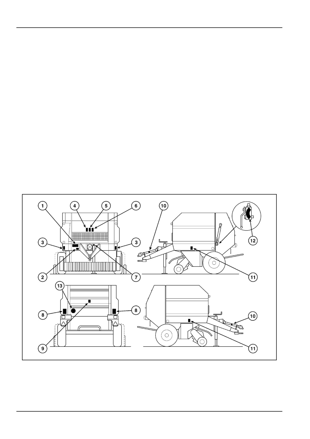
Safety decals [25659953]
Safety decals are placed on your machine as a guide for
your safety. Walk around the machine and note the con-
tent and location of these decals before operating your
machine.
Following is a listing of Safety Decals and locations with
part numbers. Read and understand them before operat-
ing the machine.
Decal Inspection and Maintenance
1.
Cleaning decals.
•
Keep decals clean and legible.
•
Use a soft cloth, water, and a gentle detergent.
•
Do not use solvent, gasoline, and other harsh
chemicals which may damage or remove the
decals.
2.
Replace all decals that are damaged, missing,
painted over or illegible. Refer to your dealer for
replacement decals.
3.
If a decal is on a part that is replaced, make sure the
decal is installed on the new part.
ZIL10FCRB063FAA
1
2 - 10
2 - SAFETY INFORMATION
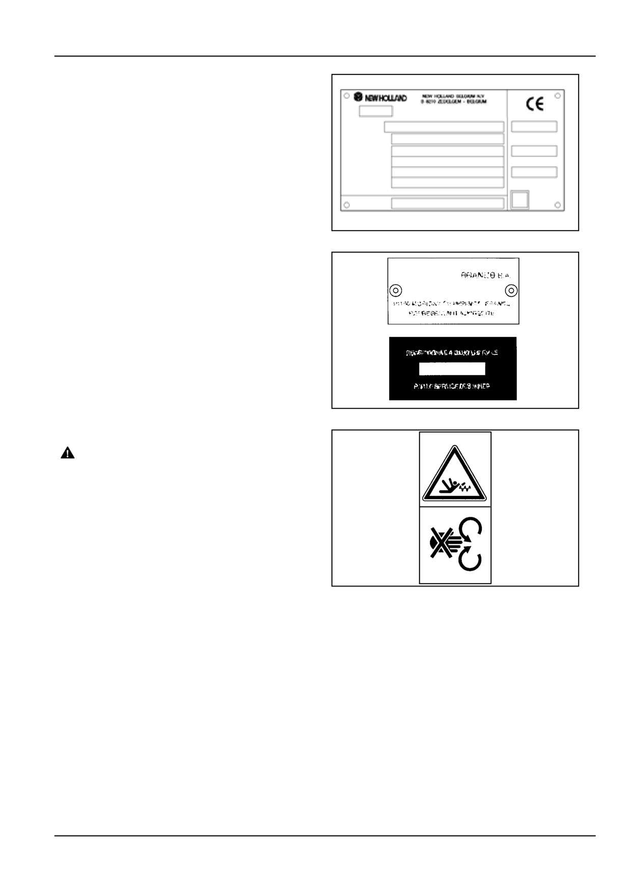
Decal 1
Identification plate identifying the manufacturer and the
machine (model, serial number, weights). It also carries
the CE mark (certification of conformity to European Di-
rectives on machine safety).
ZIL10FCRB716AAA
2
Decal 2
Optional homologation plates, as required for only some
countries.
ZIL10FCRB836AAA
3
Decal 3
WARNING
Entanglement hazard!
Disengage the Power Take-Off (PTO), turn off
the engine, and remove the key. Wait for all
movement to stop before leaving the opera-
tor's position. Never adjust, lubricate, clean,
or unplug machine with the engine running.
Failure to comply could result in death or se-
rious injury.
W0227A
•
Never reach into the rotating auger.
ZIL10FCRB157AAA
4
•
Never attempt to unplug the pickup while the tractor
engine is running.
2 - 11
2 - SAFETY INFORMATION
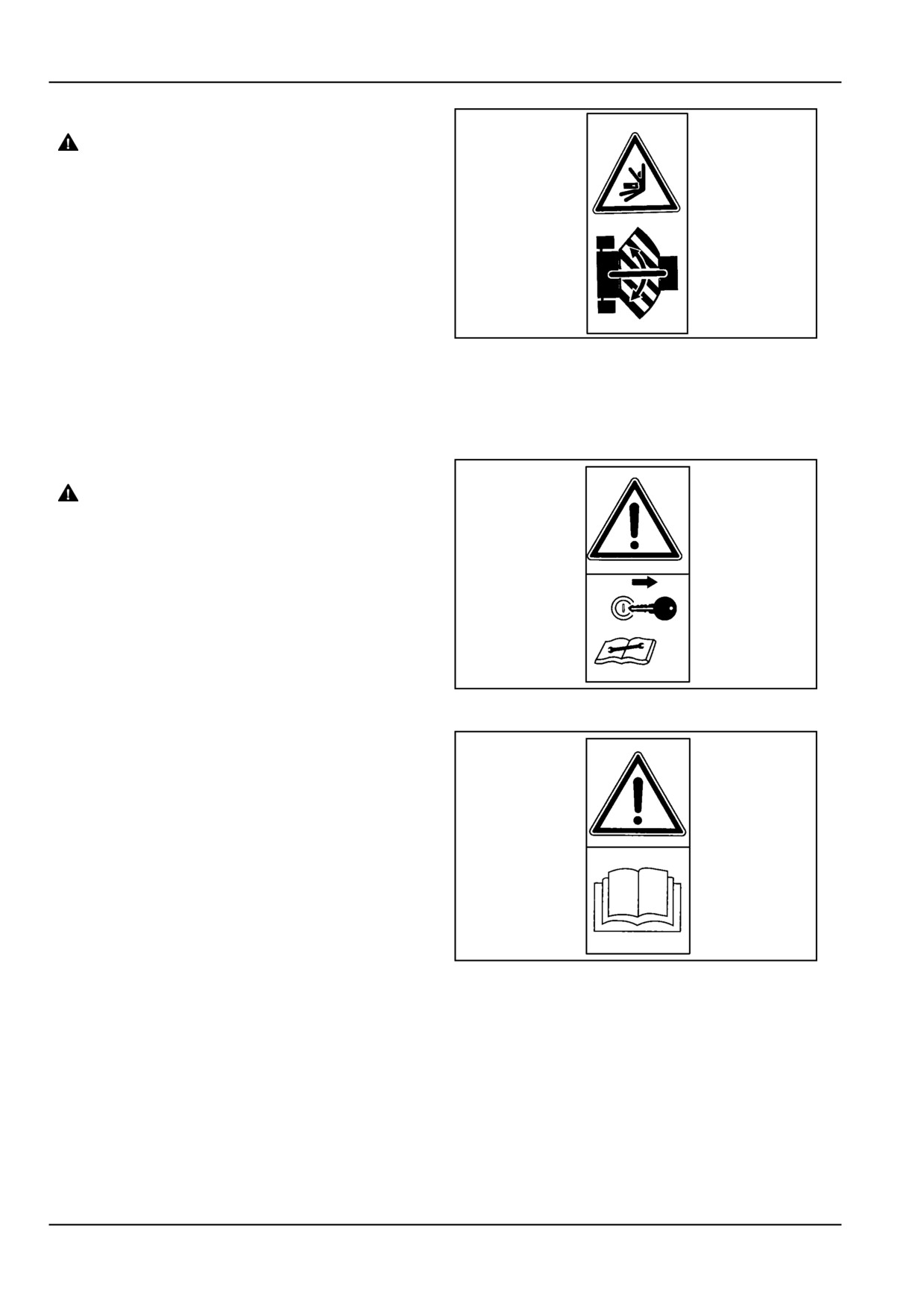
Decal 4
WARNING
Crushing hazard!
Use caution when backing the towing unit up
to the hitch. Have all persons in clear view be-
fore you start to back up. Always take the tow-
ing unit out of gear and set the parking brake
before anyone goes behind the towing unit to
check the hitch alignment.
Failure to comply could result in death or se-
rious injury.
W0961A
ZIL10FCRB160AAA
5
•
Make sure the baler hitch articulation area is free
of people and animals when moving and or during
hitch connection.
•
Use wheel chocks to immobilize the baler when
parked.
Decal 5
WARNING
Entanglement hazard!
Disengage the Power Take-Off (PTO), turn off
the engine, and remove the key. Wait for all
movement to stop before leaving the opera-
tor's position. Never adjust, lubricate, clean,
or unplug machine with the engine running.
Failure to comply could result in death or se-
rious injury.
W0227A
Apply the handbrake and block the wheels before per-
ZIL10FCRB158AAA
6
forming maintenance or repair work.
Decal 6
Carefully read the Operator's Manual before operating the
machine. Observe instructions and safety rules when op-
erating.
ZIL10FCRB155AAA
7
2 - 12
2 - SAFETY INFORMATION
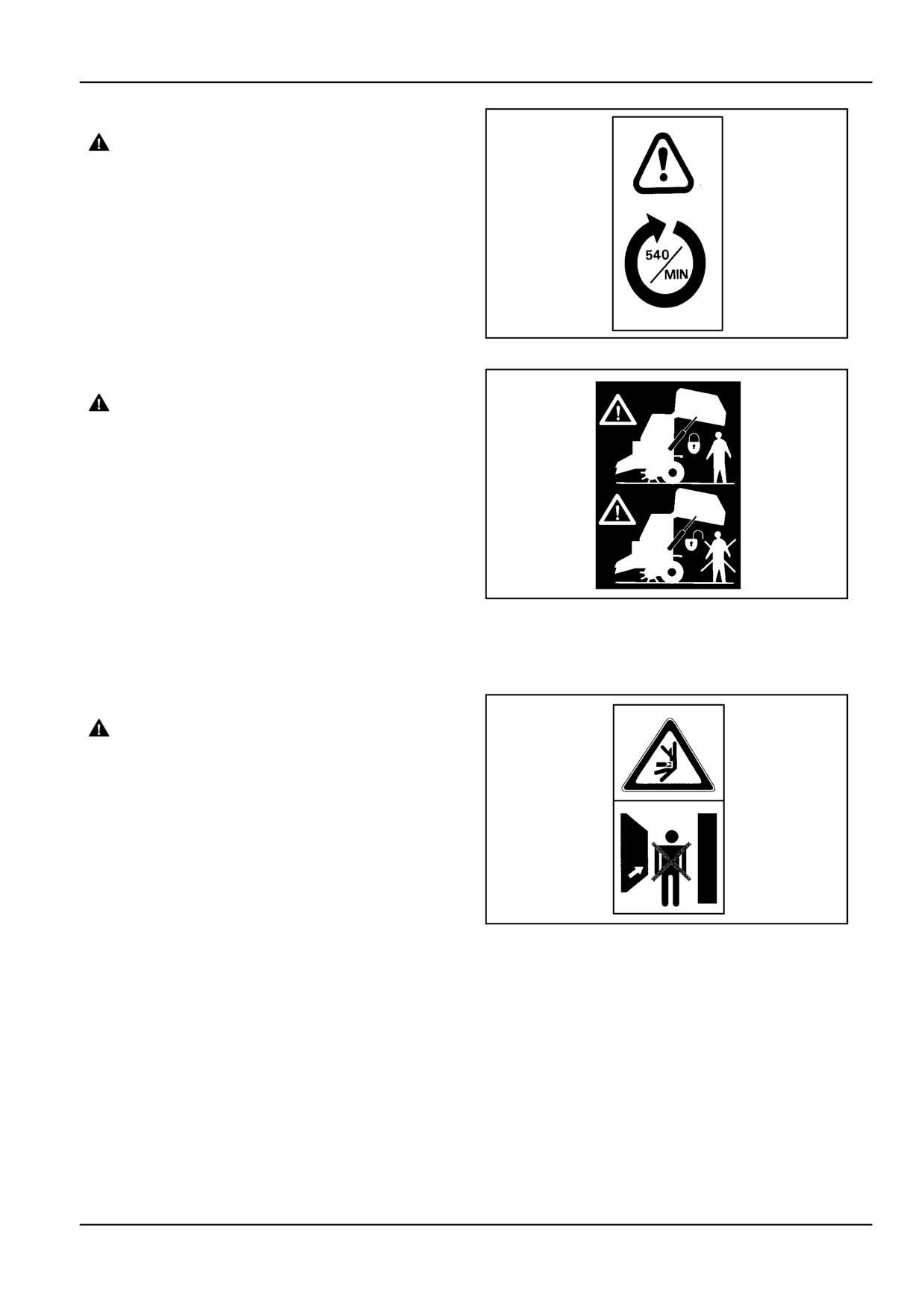
Decal 7
WARNING
Entanglement hazard!
Power Take-Off (PTO) driven machinery can
cause serious injury. Before working on or
near the PTO shaft, or servicing or clearing the
driven machine, put the PTO switch in the dis-
engage position and stop the engine.
Failure to comply could result in death or se-
rious injury.
W0321A
This machine is designed to run only at 540 RPM.
ZIL10FCRB185AAA
8
Decal 8
DANGER
Crush hazard! The tailgate may close faster
than you can move away.
ALWAYS make sure the tailgate lockout valves
are in the OFF (locked) position before work-
ing under a raised tailgate. In the event of a
sudden loss of hydraulic pressure, the tailgate
will fall if the lockout valves are not engaged.
Stand clear of the tailgate before disengaging
the lockout valves.
Failure to comply will result in death or serious
injury.
ZIL10FCRB169AAA
9
D0002A
Always apply the hydraulic lock when near an open tail-
gate.
Decal 9
DANGER
Crushing hazard!
Make sure the area surrounding the tailgate
is clear of all persons and domestic animals
before opening or closing the tailgate.
Failure to comply will result in death or serious
injury.
D0034A
Be aware potential crushing / pinching hazard.
ZIL10FCRB167AAA
10
2 - 13
2 - SAFETY INFORMATION
Decal 10
WARNING
Entanglement hazard!
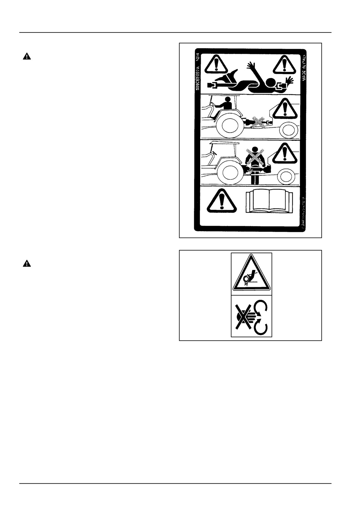
The Power Take-Off (PTO) guard must be in
place for most operations to prevent death
or injury while the PTO is operating. When
attachments like pumps are attached to the
PTO - where the guard is moved upward or
removed - shielding equal to the PTO guard
must be installed with the attachment.
Failure to comply could result in death or se-
rious injury.
W0319A
This decal is located on the PTO. telescoping shafts, out-
side and inside the PTO. guards. The inside decal is ex-
posed when the guard is missing. It warns the operator
not to operate the baler with the PTO. shaft guard miss-
ing.
ZIL10FCRB009BAA
11
Decal 11
WARNING
Entanglement hazard!
Disengage the Power Take-Off (PTO), turn off
the engine, and remove the key. Wait for all
movement to stop before leaving the opera-
tor's position. Never adjust, lubricate, clean,
or unplug machine with the engine running.
Failure to comply could result in death or se-
rious injury.
W0227A
•
Keep all safety guards in place.
ZIL10FCRB156AAA
12
•
Do not open or remove safety guards while the trac-
tor engine is running.
•
Do not reach through inspection doors while the
tractor is running.
•
Wait until all parts have stopped before carrying out
any maintenance work on the baler.
•
Stand clear from all moving parts.
2 - 14
2 - SAFETY INFORMATION
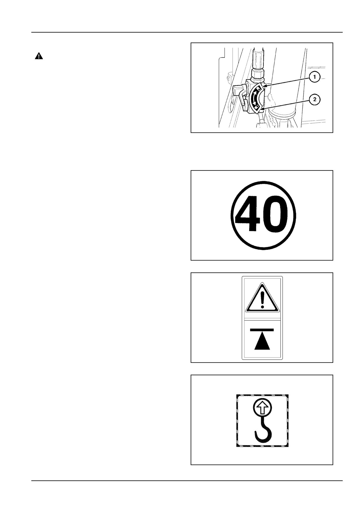
Decal 12
DANGER
Crush hazard! The tailgate may close faster
than you can move away.
ALWAYS make sure the tailgate lockout valves
are in the OFF (locked) position before work-
ing under a raised tailgate. In the event of a
sudden loss of hydraulic pressure, the tailgate
will fall if the lockout valves are not engaged.
Stand clear of the tailgate before disengaging
the lockout valves.
Failure to comply will result in death or serious
injury.
ZIL10FCRB150AAA
13
D0002A
Position 1: Lever horizontal tailgate is locked.
Position 2: Lever vertical tailgate is unlocked.
Decal 13
For machines delivered ex-factory with high hitch Ger-
many only: 40 kPa with brakes, 30 kPa brakes.
This decal indicates that the machine axle and wheel as-
sembly is designed for a maximum of 40 km/h transport
speed on good public road.
This decal is not a substitute for the speed regulations
signs imposed by law.
Check with your dealer to equip your machine with the ap-
propriate additional speed regulation signs in accordance
with road traffic regulations in your country.
ZIL10FCRB201AAA
14
Only use the indicated places on the baler axle(s) to lift up
the machine using a lifting jack.
Use only lifting equipment capable to take the weight of
the baler, refer to Specifications section.
ZIL10FCRB250AAA
15
For moving the baler with heavy handling equipment, sling
the cables on the top of the baler where the decals are
located.
ZIL10FCRB002AAA
16
2 - 15

2 - SAFETY INFORMATION
Ensure the tire pressures are maintained as per the tire
inflation decal.
ZIL10FCRB835AAA
17
2 - 16
2 - SAFETY INFORMATION
Safety Features [25716851]
Safety guards
WARNING
Illustrations in this manual may show protec-
tive shielding open or removed to better illus-
trate a particular feature or adjustment.
Replace all shields before operating the ma-
chine.
Failure to comply could result in death or se-
rious injury.
W0012A
WARNING
Moving parts!
Make sure all entry and mechanical access
doors are properly closed before operating the
machine.
Failure to comply could result in death or se-
rious injury.
W0238A
Safety guards
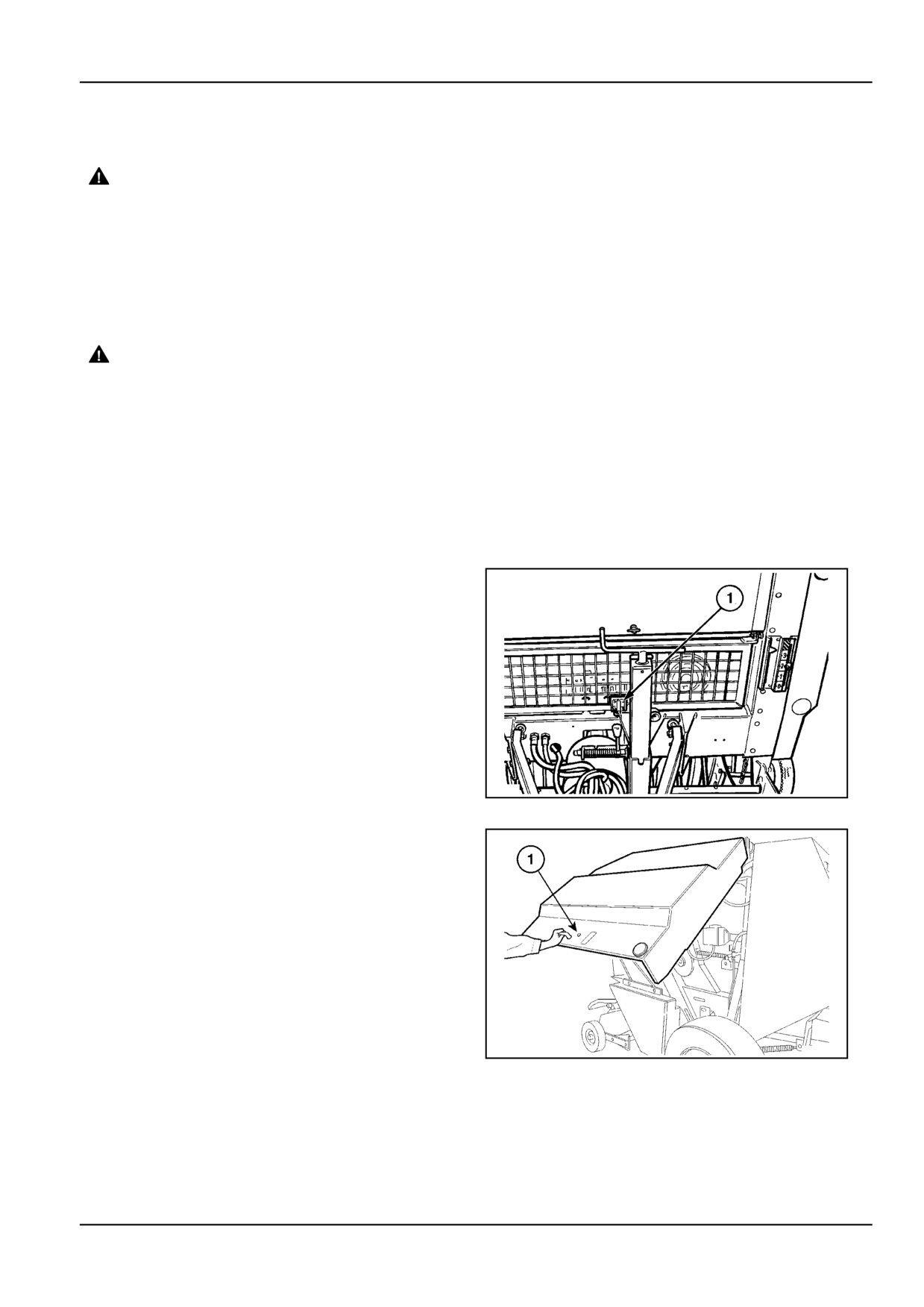
The lower front guard is locked with a manual latch (1).
When unlatched, the guard swings open to the inside of
the baler and can be locked in open position. Keep the
guard closed during operation.
ZIL10FCRB827AAA
1
The main side guards are provided with an automatic latch
(1). They swing open.
Stand clear, they have spring-load assist to open.
ZIL10FCRB805AAA
2
2 - 17
2 - SAFETY INFORMATION
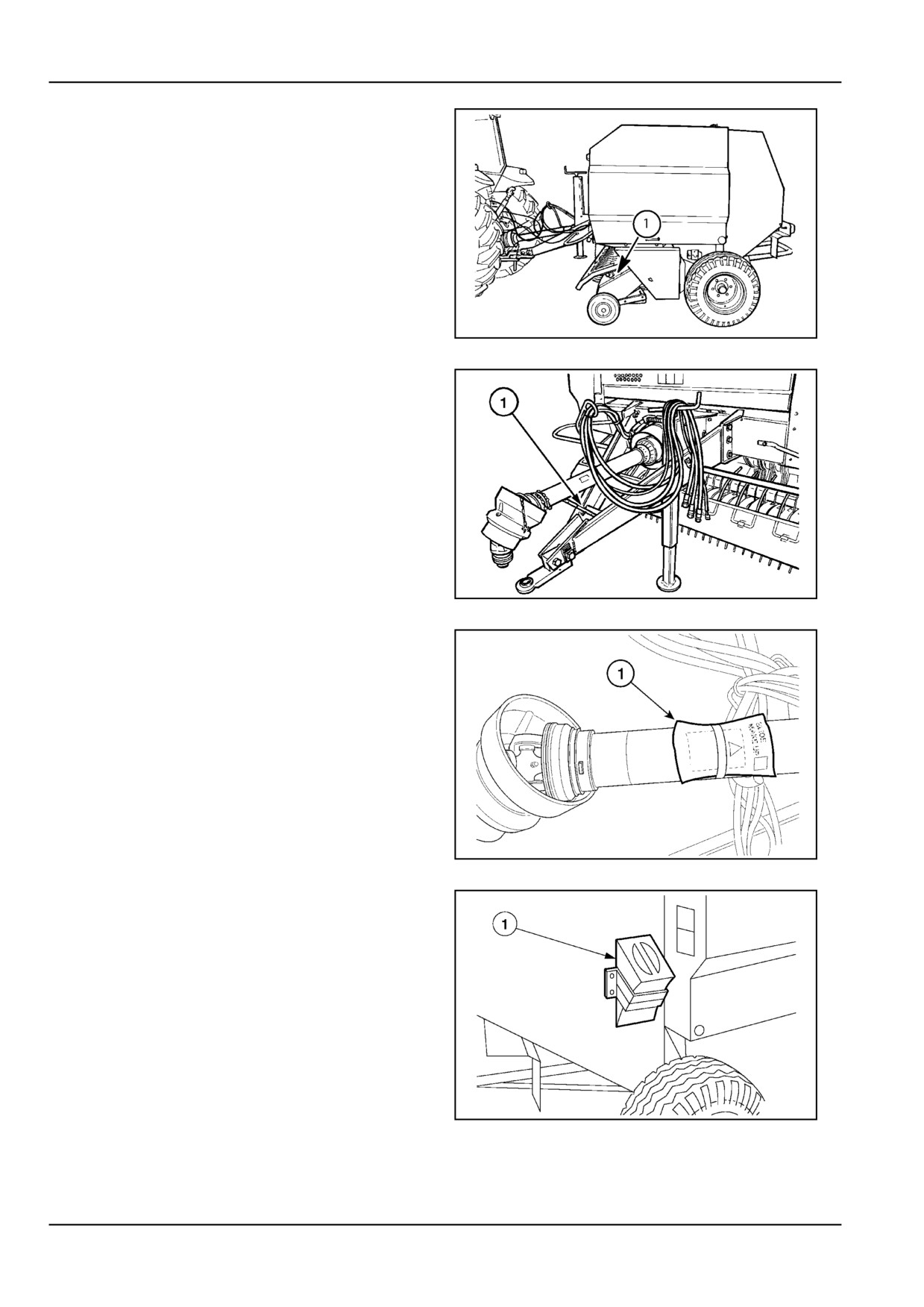
Pick-up guards have a half twist locking device (where
fitted) for access.
ZIL10FCRB717AAA
3
PTO shaft support
The PTO shaft support (1) is designed to support the PTO
shaft when the baler is parked.
ATTENTION: The baler must not be operated or trans-
ported with the PTO shaft resting on the support.
ZIL10FCRB093AAA
4
PTO instruction booklet
A booklet (1) with specific PTO safety instructions is at-
tached to the PTO shaft when the baler is originally sup-
plied to you. Retrieve the booklet, read, understand and
keep it with this manual for future reference.
ZIL10FCRB804AAA
5
Wheel chocks (where fitted)
The baler maybe equipped with wheel chocks (1) stored
on the tailgate side panels. Use these wheel chocks
whenever the machine is parked or uncoupled from the
tractor.
Place them at the lower side of the left and right tyre to
immobilize your baler if it is left on sloping ground.
Place a wheel chock on both sides of one tyre if the ground
is flat.
ZIL10FCRB718AAA
6
2 - 18
2 - SAFETY INFORMATION
Service steps
NOTICE: The machine has no service steps, there will
normally be no need to step onto the machine.
Should any situation require to get up to upper machine
components, use safe and stable steps or a ladder struc-
ture.
Tailgate [26071003]
Tailgate lock
DANGER
Crush hazard! The tailgate may close faster
than you can move away.
ALWAYS make sure the tailgate lockout valves
are in the OFF (locked) position before work-
ing under a raised tailgate. In the event of a
sudden loss of hydraulic pressure, the tailgate
will fall if the lockout valves are not engaged.
Stand clear of the tailgate before disengaging
the lockout valves.
Failure to comply will result in death or seri-
ous injury.
D0002A
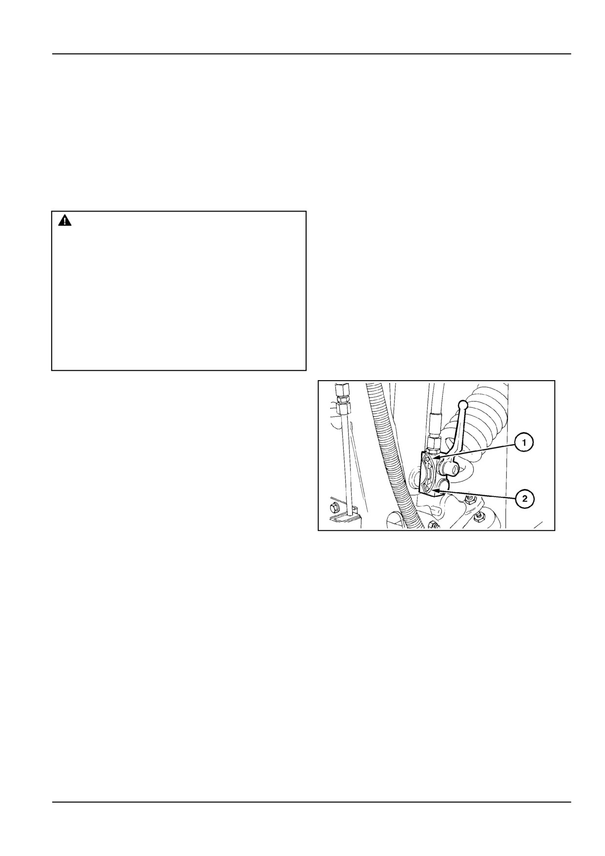
Engage the tailgate lock before working under or around
the tailgate in the raised position. Stand clear before un-
locking the tailgate lock.
1: Lever vertical: tailgate is unlocked.
2: Lever horizontal: tailgate is locked.
ZIL10FCRB638AAA
1
2 - 19
2 - SAFETY INFORMATION
2 - 20
3 - CONTROLS/INSTRUMENTS
3 - CONTROLS/INSTRUMENTS
Monitor Operation
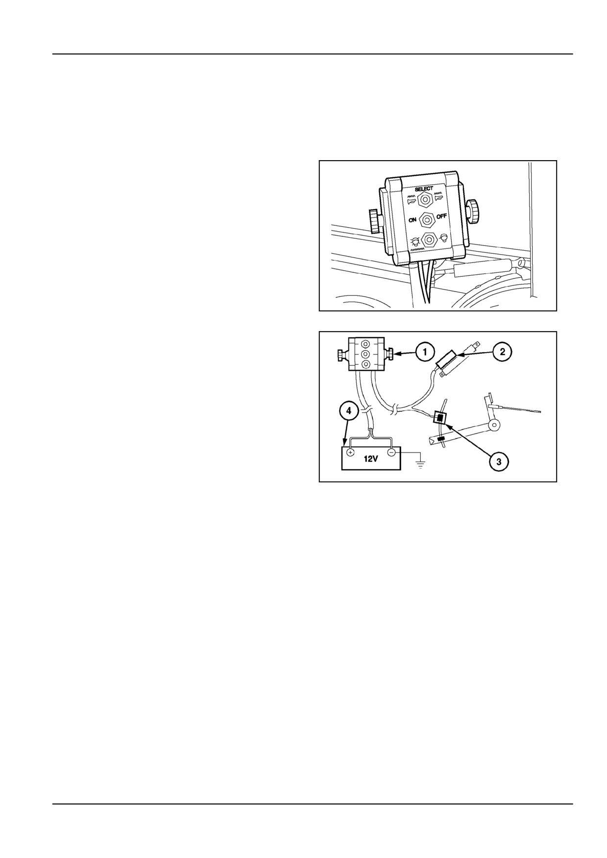
Baler Operator Controls Control box (Optional) [31613027]
Install the control box on a support inside the tractor cab or
on the fender in a comfortable reach field from the tractor
seat.
ZIL10FCRB750AAA
1
Connect the power cable to a 12 V power source in the
tractor cab, capable of supplying 15 A peak load, or di-
rectly to the battery.
ATTENTION: Connect the red wire to the plus pole of the
battery. If not, the actuator will extend automatically to
full extend position whenever the control box is turned on.
This will result in malfunction of the twine wrapper.
1.
Control box.
2.
Actuator.
3.
Magnetic full bale switch.
4.
12 V power source.
ZIL10FCRB751AAA
2
The system provides the following features to the opera-
tor:
•
Manual electric control over twine wrap start
•
Audible alarm at full bale density
•
Acoustic signal when the tailgate latches
The electric control box system consists of the following
components:
3 - 1
3 - CONTROLS/INSTRUMENTS
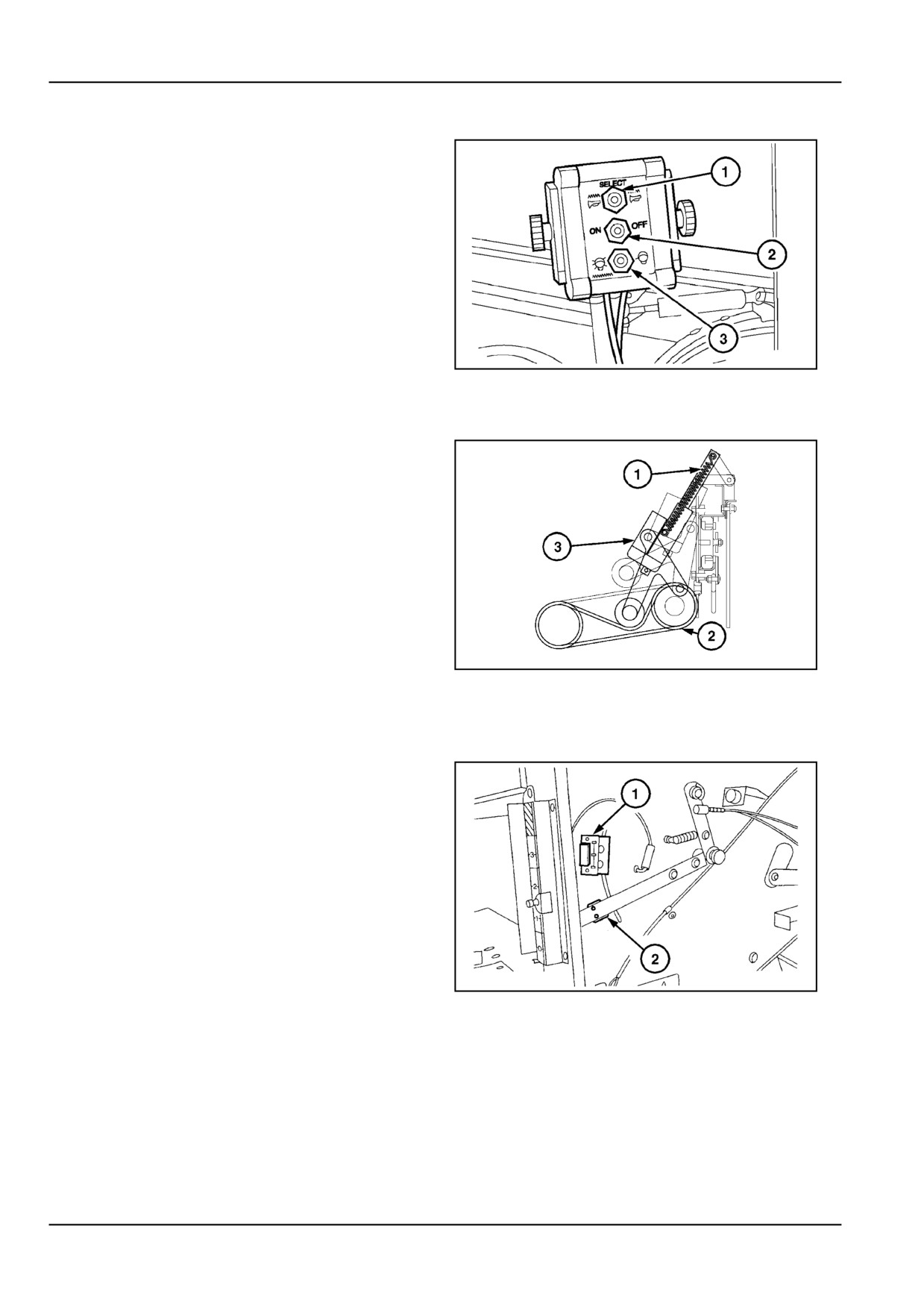
Control box (Where fitted)
1.
ALARM level switch: to set the sound level of the
audible alarm.
2.
ON/OFF switch: to turn the system on or off.
3.
WRAP switch: to initiate a wrap cycle.
NOTE: The WRAP switch is a rocker type switch. This
means that it will always come back to its original position
when it is released.
ZIL10FCRB803AAA
3
Electric actuator (Only with control box)
Toggling the WRAP switch will extend the electric actuator
(3) to apply tension on the wrapper drive belt (2). As soon
as the switch is released, the actuator will automatically
retract to the home position.
The overload spring (1) prevents the drive belt from being
over tensioned.
The actuator has an internal circuit with end-of-stroke con-
tacts. They will shut off power when the actuator reaches
the minimum or maximum position.
ZIL10FCRB726AAA
4
Full bale alarm switch (Only with control
box)
An adjustable magnetic switch
(1) connected to the
buzzer is located on the baler frame left-hand side sheet.
A magnet (2) on the left density indicator will activate the
switch when the set full bale density is reached. Then the
operator has to start the wrap cycle with the WRAP key.
After the wrap cycle has ended and the bale has been
ejected, the operator will hear a short beep as the tailgate
closes and latches.
ZIL10FCRB760AAA
5
3 - 2
3 - CONTROLS/INSTRUMENTS
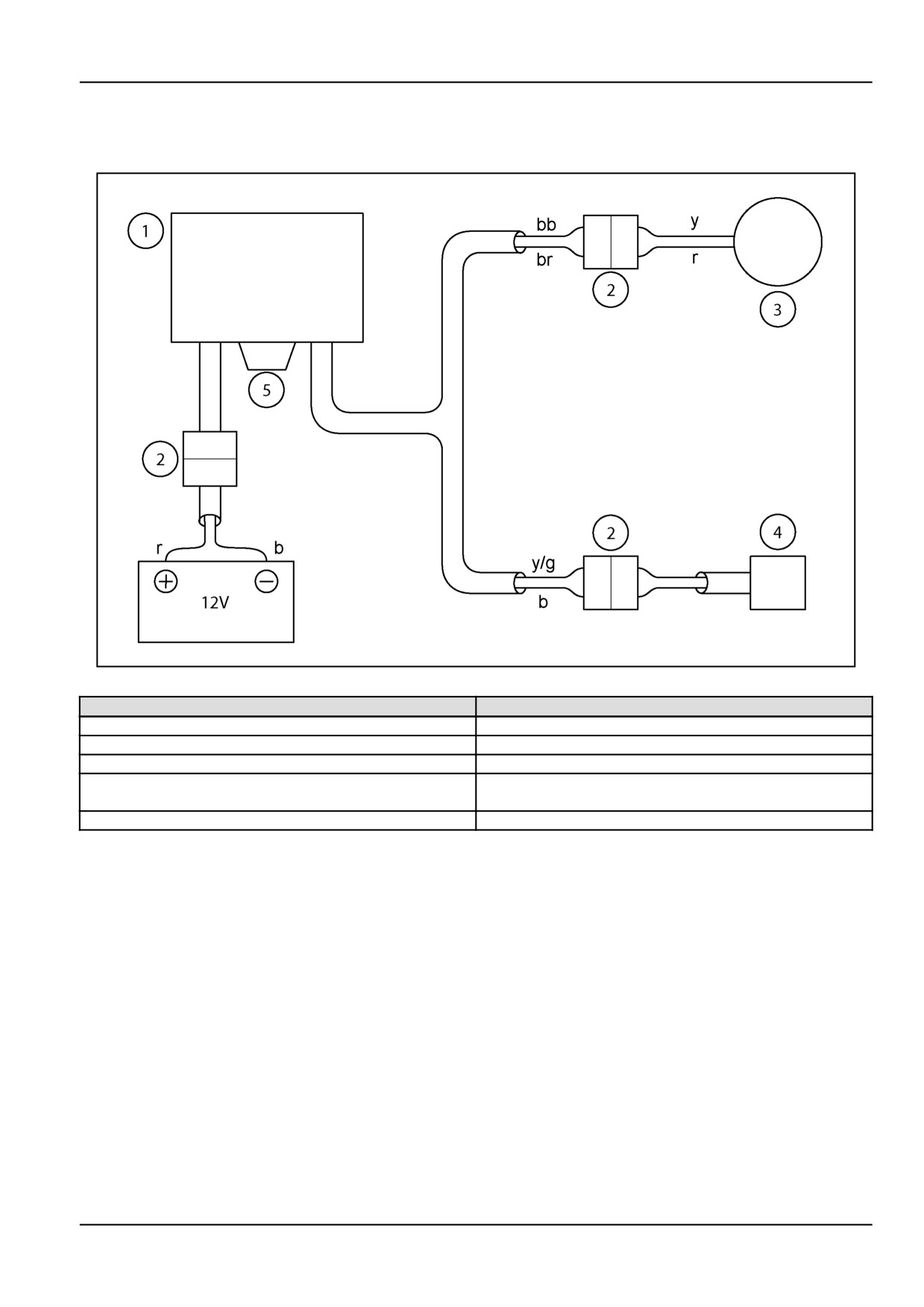
Wiring diagram
Electric control box system.
ZIL10FCRB059FAA
6
Components
Colour code
1. Control box
b black
2. Connector
bl blue
3. Actuator
br brown
4. Magnetic switch
y yellow
y/g yellow/green
5. Fuse, 6.3 A
r red
3 - 3
3 - CONTROLS/INSTRUMENTS
3 - 4
4 - OPERATING INSTRUCTIONS
4 - OPERATING INSTRUCTIONS
COMMISSIONING THE UNIT
Machine safety [25785854]
Safety - Shut down tractor
Some functions of your baler are controlled by soft-
ware and some of them are safety related. Do
It is of the utmost importance to shut down the tractor PTO
not attempt to modify or download software from
and engine, when doing an intervention on the baler.
spurious sources. Settings and logics may be de-
stroyed and affect seriously the function of the ma-
This is by far the safest practice. If and despite of this
chine. This may result in unpredictable and unsafe
warning, you will proceed without shutting off the tractor
behaviour of the machine. Only your dealer is enti-
PTO. and/or the tractor engine, it is of vital interest to lock
tled to intervene on the software of the machine. He
out the automatic triggered devices on your baler.
has the appropriate tools and data sets for it and
owns the officially released software versions and
There are locking systems on the baler, refer to Safety
updates for your machine.
section.
3.
Safety functions
Failing to use these locking devices while intervening on a
running baler, may cause fatal injury when above systems
Your baler is equipped with a number of sensors to
are inadvertently triggered (e.g. when the system is at the
control safety functions.
point of being triggered).
Do not attempt to bypass any function. You will be
ATTENTION: The following statements are identified to
exposed to serious hazards, and moreover, the be-
draw the attention of the operators to their machine and
haviour of the machine may become unpredictable
surroundings, read these statements before starting any
when messing up wires.
baler operations.
4.
Bystanders
1.
Intended use and reasonable foreseeable misuse
You shall take the necessary precautions (e.g. as-
Your baler is designed and made to work in a vari-
sistance) to always be aware of the possible pres-
ety of crops and conditions and within some physi-
ence of bystanders, certainly when manoeuvring in
cal limits. The feed rate and performance may de-
confined areas, such as the farm yard and sheds.
pend on a number of limitative parameters, such as
weather and terrain conditions, crop variety and hu-
Keep people away from the baler during field work.
midity. Though the machine is designed to perform
Ask bystanders to leave the field. There is the risk
in most crops and conditions, there may be a num-
to be overrun by the machine, in particular when
ber of combinations of above parameters, for which
reversing.
there is severe degradation of performance of the
machine or systems thereof. If you notice degra-
Do not allow riders on the machine; do not allow
dation of performance, contact your dealer for as-
people standing on the machine when baling. A
sistance. He may have useful information for im-
rider risks to fall from the machine during unfore-
provements, or a kit may be available to enhance
seen or abrupt movements of the combination trac-
the performance.
tor - baler.
5.
Other requirements: scope of this manual
Do not use your machine for another purpose than
intended by the manufacturer and within its limits
Clear distinction between the different phases of
(*).
machine use (and the corresponding level of train-
* limits of the machine:
ing needed) shall be part of the introduction:
* side slope: %
* tractor properties: power, traction performance
This manual gives information for use of this baler,
* maximum throughput: variable, depending of
as intended and under the conditions foreseen by
crop, variety, maturity, humidity
the manufacturer during normal operation and rou-
* maximum baling speed: variable, depending of
tine service and maintenance.
crop, variety, maturity, humidity, grain losses, tractor
engine power and power transmission
Normal operation means the use of the machine
* mobility: variable, soil condition.
for the purpose intended by the manufacturer by
2.
Software
an operator familiar with the machine characteris-
tics and complying with the information for operation
4
-
1
4 - OPERATING INSTRUCTIONS
and safe practices, as specified by the manufacturer
Periodical service means activities that must be
in this manual and by the signs on the machine.
done at defined intervals by trained personnel fa-
miliar with the machine characteristics and which
Normal operation includes the preparation and stor-
are complying with the information for periodical
age of the machine, swinging components into work
service and safe practices, as specified by the
position and vice versa, filling the baler with twine
manufacturer in this manual and in other Company
spools, routing twine and setting off the baler from
literature, in order to maintain the expected life time
a tractor.
of the baler.
Normal operation includes the adjustment and set-
Periodical service includes activities such as chang-
ting of the machine, for the specific condition of the
ing oil from the hydraulic circuit or gearboxes, or
field and/or the crop.
other substances or components that need period-
ical exchange.
Routine service and maintenance means activities
that must be done daily by an operator familiar with
Converting (rebuild) means activities that must be
the machine characteristics and complying with the
done by professional service personnel familiar with
information for routine service and safe practices,
the machine characteristics and complying with the
as specified by the manufacturer in this manual and
information for converting, as specified by the man-
by signs on the machine, in order to maintain the
ufacturer in this manual, in assembly instructions or
proper function of the machine.
in other Company literature, in order to rebuild the
machine to a configuration which is appropriate for
Routine service includes activities such as cleaning,
a specific crop or soil condition.
washing, topping up fluid levels, greasing, adjusting
belts and chains, replacement of consumable arti-
Repair means activities that must be done by pro-
cles and fast wearing parts, such as twine guides.
fessional service personnel familiar with the ma-
chine characteristics and complying with the infor-
This manual is not giving all the information related
mation for repair, as specified by the manufacturer
to periodical service, machine converting (rebuild)
in the dealer's workshop manual, in order to restore
and repairs to be carried out by professional service
the proper function of the machine after a failure or
personnel. For some of the latter activities, there
degradation of performance.
may be a need for appropriate facilities, technical
skills and tools which are not supplied with the ma-
The machine is a one man operated machine, i.e.
chine. Failing one of these 3 prerequisites, makes
the driver of the tractor. There is no need for other
that these activities shall be done by your dealer.
people on or around the machine during normal op-
eration.
4 - 2
4 - OPERATING INSTRUCTIONS
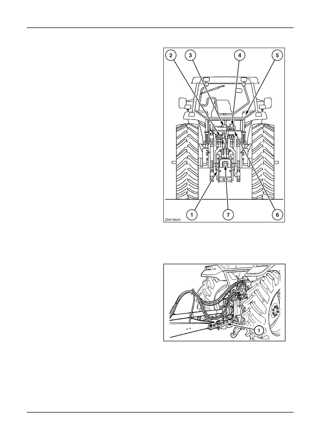
Tractor attachment [31309693]
The tractor and baler when attached must meet all Road
and Towing Legislation applicable to country where oper-
ated.
The tractor must also be suitable for the application, in-
clines will require a larger tractor than flat lands.
IMPORTANT: When attaching the baler wrapper to the
tractor ensure that all the services are connected correctly
and the following criteria are met:
1. Adjust the tow hitch settings.
2. Connect the baler to a remote valve on the tractor for
correct operation,
Hose identified Green = Baler pickup
Hose identified blue = Rotor reverser (where fitted)
3 Where equipment requires a return of oil to tank, refer
to the Tractor Operator's Manual for more information.
4. Connect the trailer socket if the baler wrapper is to be
towed on public roads.
5. Connect the control panel which requires a 12 V unin-
terrupted supply.
6. Connect the trailer brakes and test them.
7. Connect to the Power Take Off 540 RPM.
ZDA7982A
1
Tractor attachment [25662727]
Power Take Off shaft
The baler is equipped with a PTO drive shaft with front
yoke for attaching to a 35 mm diameter, 6-splines PTO
tractor shaft and is designed to operate at 540 RPM PTO
speed.
ZIL10FCRB052AAA
1
4 - 3

4 - OPERATING INSTRUCTIONS
Tractor drawbar
The drawbar tongue on the baler is adjustable in height
and is reversible, so the baler can be attached either to
a clevis-type swinging drawbar (1) Figure 1, or a rear tow
hook (1) Figure 2, on the tractor.
ZIL10FCRB086AAA
2
4 - 4
4 - OPERATING INSTRUCTIONS
ZIL10FCRB001FAA
3
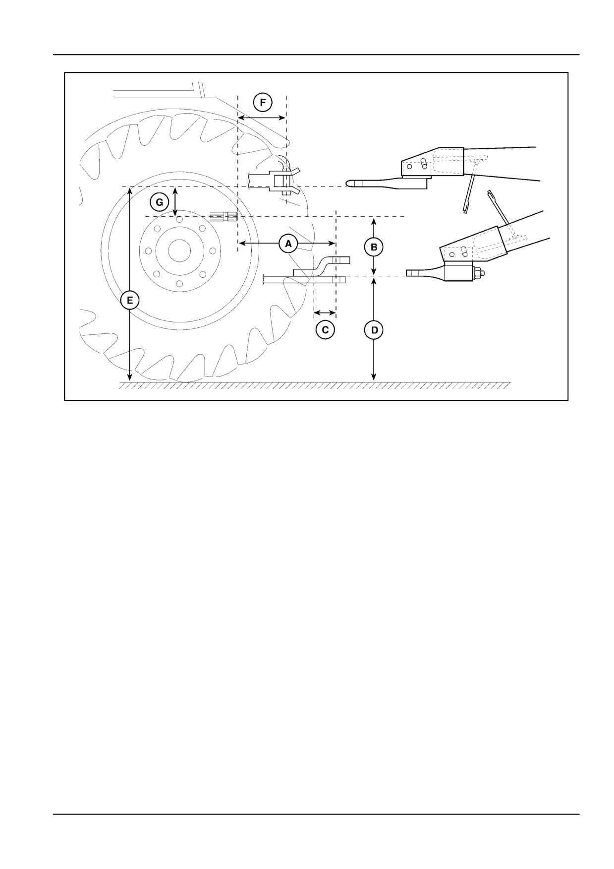
Ensure the tractor drawbar is adjusted to meet the stan-
Secure the tractor drawbar so the hitch pin hole is directly
dard specifications:
below the power driveline.
•
Swinging drawbar:
•
Rear tow hook:
A.
35 cm
E.
75 cm to 100 cm
B. Between 15 cm and 30 cm
F.
18 cm
C. Minimum 10 cm
G.
20 cm
D. Between 45 cm and 50 cm
4 - 5
4 - OPERATING INSTRUCTIONS
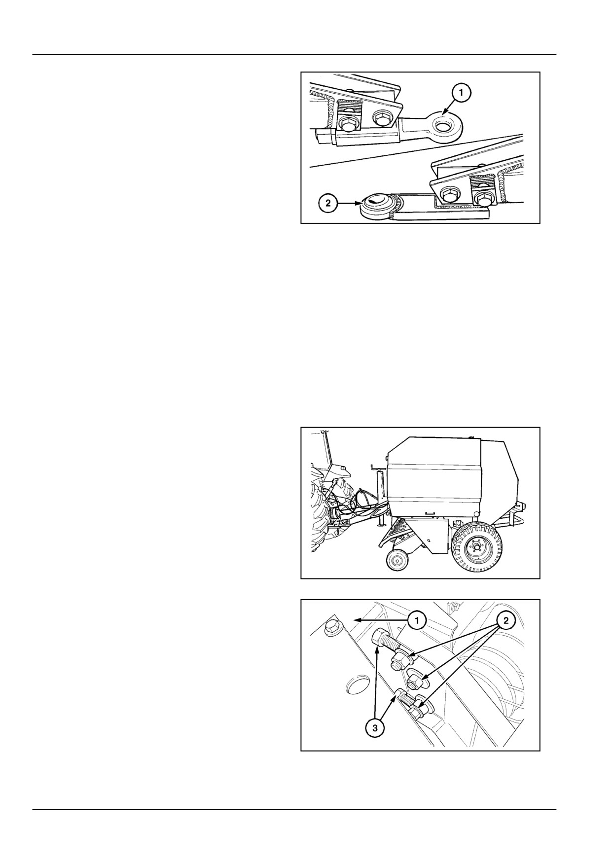
To fit to the swinging drawbar (low tongue position on the
baler), depending on country-bound legal regulations the
baler tongue is equipped with either Figure 4:
•
A pivotable ring hitch (1)
•
A swivel ball hitch (2)
NOTE: The swivel ball hitch will also fit to the rear tow
hook, if legally allowed.
ZIL10FCRB081AAA
4
To fit to the rear tow hook (high tongue position on the
baler), the baler tongue is equipped with a fixed ring hitch.
Make sure the tractor hitch pin matches the bore in the
baler hitch:
•
Swivel ball hitch: 33 mm pin hole for a 30 mm to 32
mm pin
•
Pivotable ring hitch: 35 mm pin hole for a 25 mm to
27 mm pin
•
Fixed ring hitch: 40 mm pin hole for a 30 mm to 32
mm pin.
Levelling the Baler
Adjust the baler tongue to suit the tractor hitch height so
that the baler's coach-work is parallel or slightly higher at
the front, in relation to the ground.
ZIL10FCRB047AAA
5
Proceed as follows:
1.
Let the jack stand down to support the baler. Do not
detach the baler from the tractor as shown in Figure
17 and Figure 18.
2.
Slacken the three bolts (2) on both sides of the baler
tongue, Figure 6.
3.
Alternately loosen and tighten the jam nuts (3) nuts
both inside and outside of the cross beam (1) to
move the tongue to the desired height. Turn the jack
handle to adjust the inclination of the baler.
ZIL10FCRB090AAA
6
4 - 6
4 - OPERATING INSTRUCTIONS
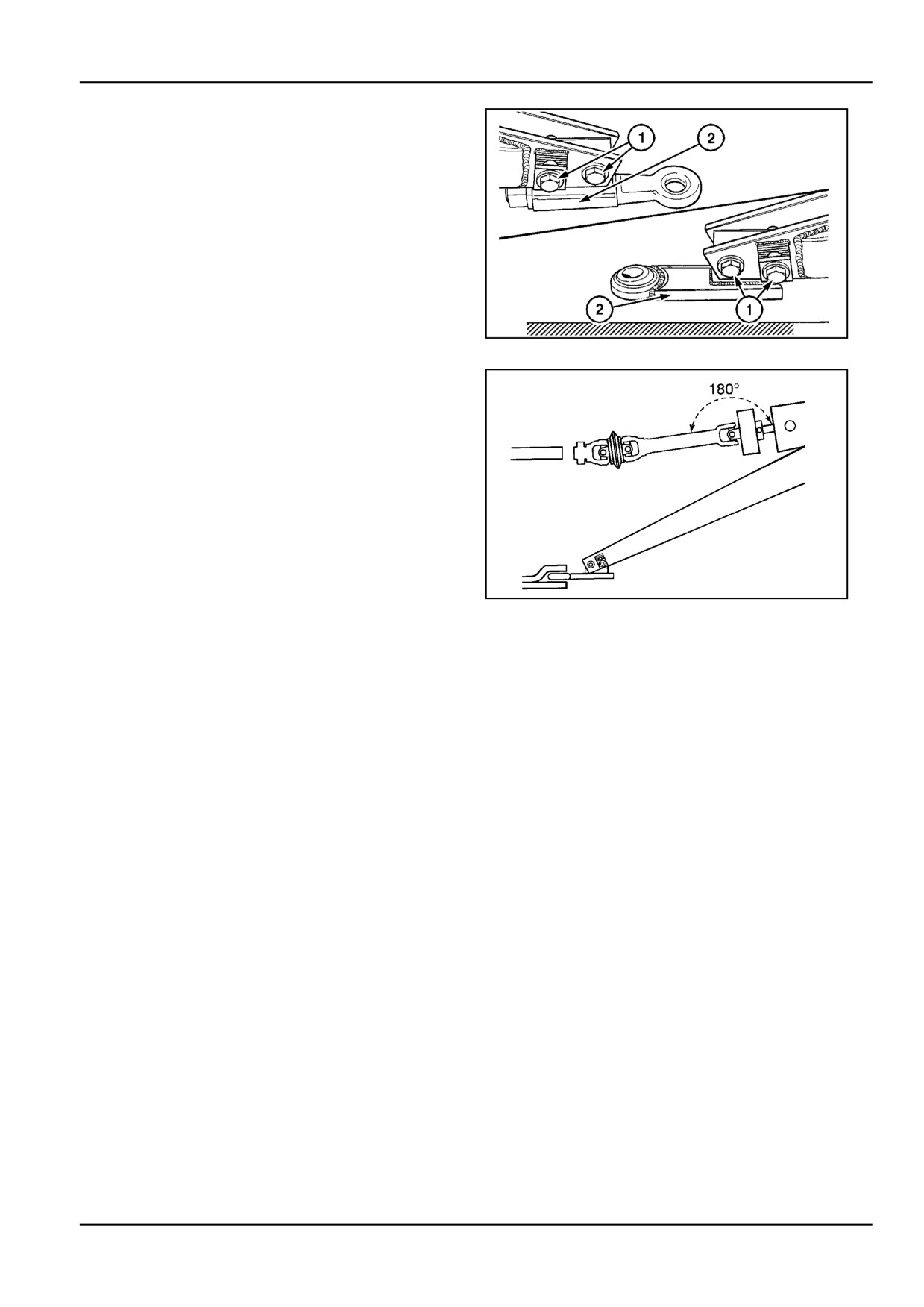
4.
Tighten the jam nuts (3) Figure 6.
5.
Torque the bolts (2) to 240 N·m (177.0 lb ft) Figure
6.
6.
Fine-adjust the inclination of the hitch plate (2) to be
parallel to slightly lower at the front in relation to the
ground.
Torque the bolts (1) to 485 N·m (357.7 lb ft) Figure
7.
7.
Raise and lock the jack stand in the highest position
and wind the jack handle until the foot is jammed
under the tongue as shown in Figure 17 and Figure
18.
ZIL10FCRB056AAA
7
NOTICE: In adjusting tractor and baler hitch height, also
strive to line up the PTO drive shaft with the gearbox input
shaft as straight as possible for smooth running of the
baler drive lines.
ZIL10FCRB082AAA
8
4 - 7
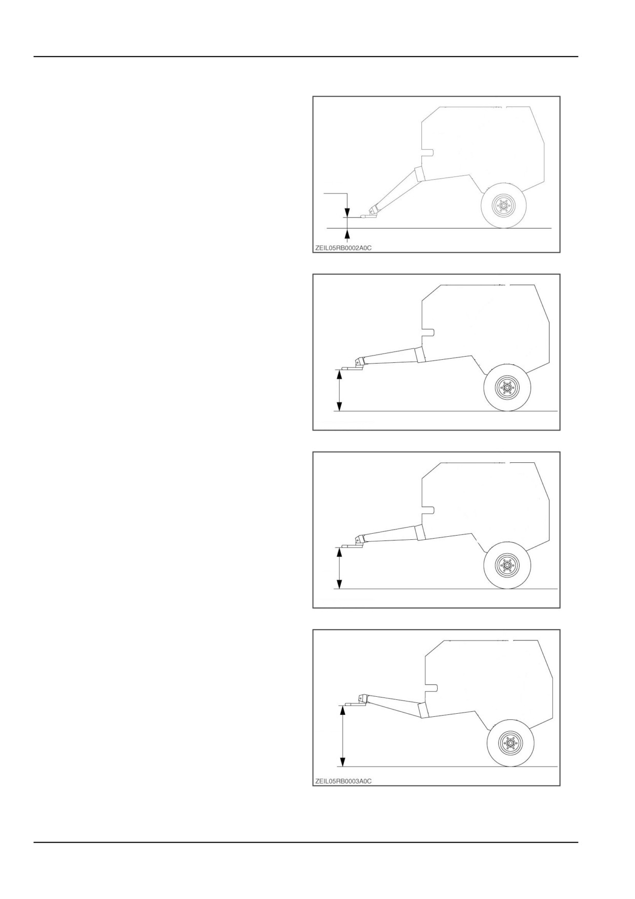
4 - OPERATING INSTRUCTIONS
Possible hitch heights
Ball hitch height low setting is: 220 mm (8.7 in).
HH1
9
Ball hitch height high setting is: 625 mm (24.6 in).
HH2
10
Fixed hitch height low setting is: 685 mm (27.0 in).
HH3
11
Fixed hitch height high setting is: 1120 mm (44.1 in).
HH4
12
4 - 8
4 - OPERATING INSTRUCTIONS
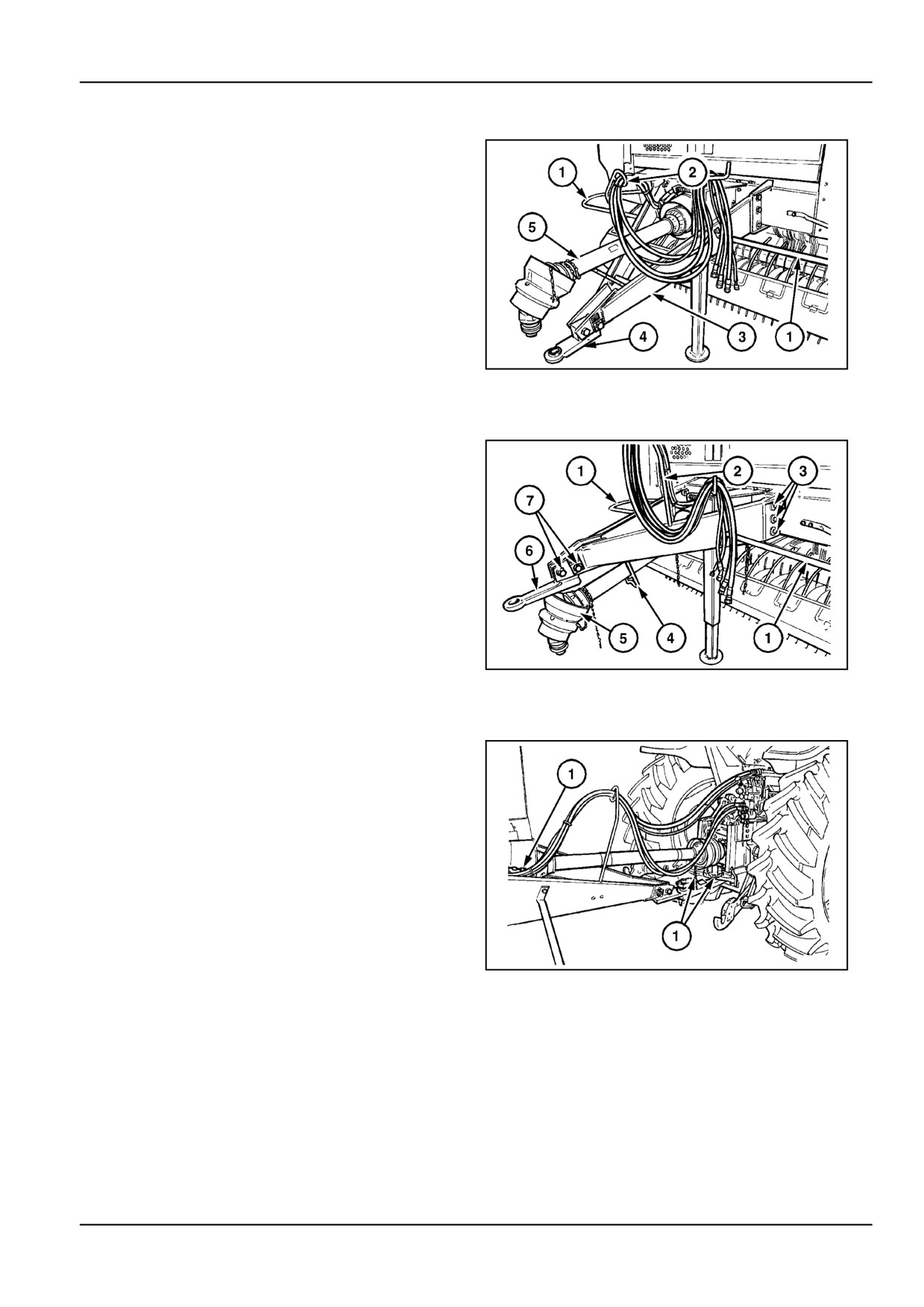
Hitch reversal - high to low
Depending on customer preference, the tongue can be
reversed from low to high position, or vice versa.
Proceed as follows:
1.
Support the baler on the jack stand.
2.
Remove the PTO front half (5).
3.
Remove hitch (4) and support (2) from tongue (3).
4.
Detach safety rails (1) from the tongue and the baler
frame.
5.
Remove tongue (3) from the baler, turn it upside
down and reinstall it to the baler.
ZIL10FCRB061AAA
13
Hitch reversal - low to high
1.
Reinstall hitch (6) on the low side of the tongue.
2.
Adjust tongue and hitch for proper height to level the
baler as explained in the previous paragraph.
3.
Tighten:
bolts (3): 240 N·m (177.0 lb ft).
bolts (7): 485 N·m (357.7 lb ft).
4.
Reinstall support (2).
5.
Reinstall the rails (1) to the opposite sides of re-
moval.
6.
Reinstall the PTO front half (5) and place it into sup-
port (4).
ZIL10FCRB062AAA
14
Hitch and PTO
1.
Secure the hitch to the tractor drawbar. Use a pin of
proper size, quality and length. Secure the pin with
a spring clip.
The pin must not protrude below the drawbar more
than necessary to install the spring clip. If not, the
pin may catch and bunch up material under the
drawbar and possibly plug the pickup when the
material breaks loose.
ZIL10FCRB053AAA
15
4 - 9
4 - OPERATING INSTRUCTIONS
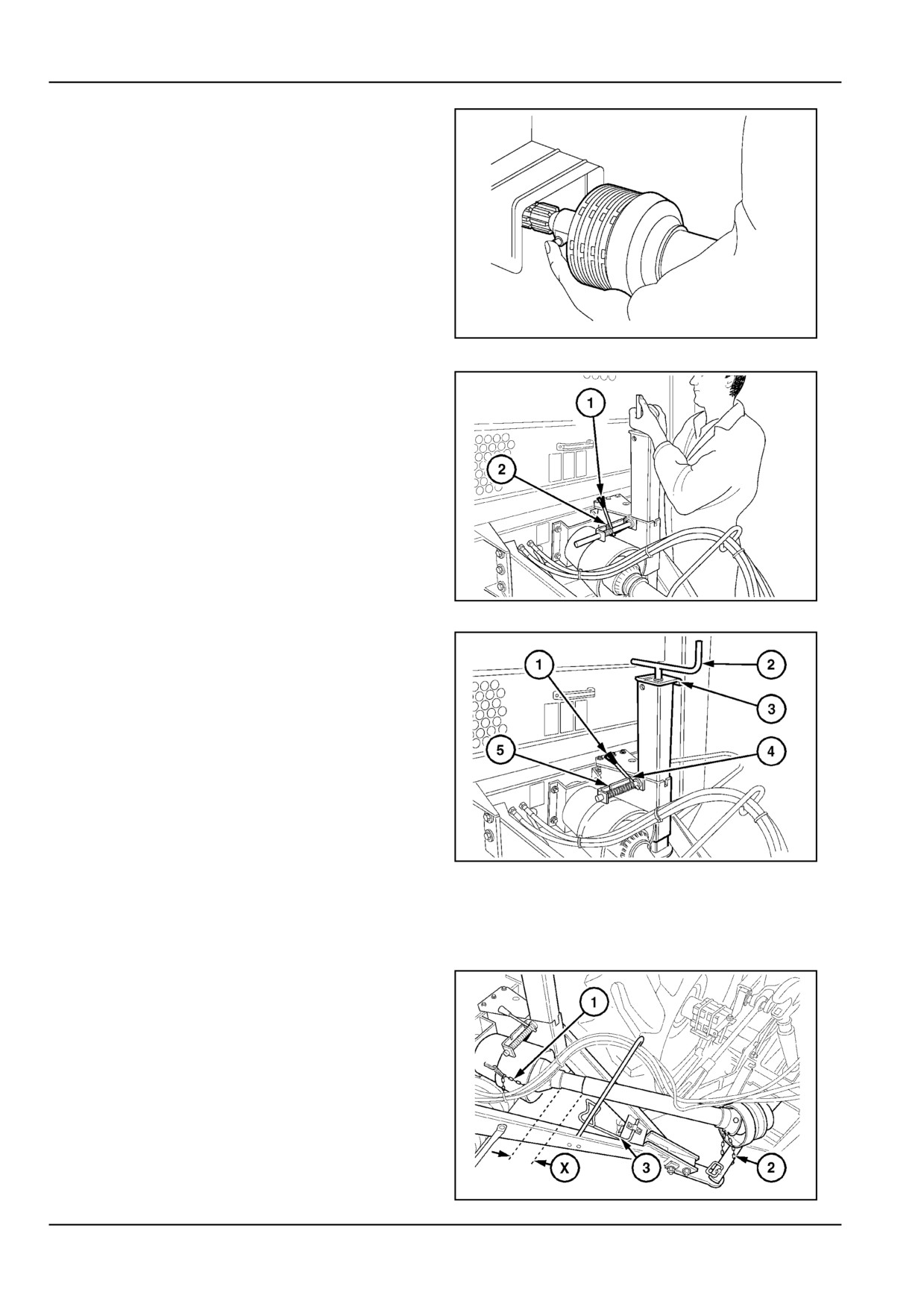
2.
Connect the PTO to the tractor.
The front PTO yoke is equipped with a push pin.
Press the spring-loaded pin and simultaneously
glide the PTO on the tractor shaft until the pin en-
gages. With the pin engaged, try to move the PTO
back and forth to ensure it is locked on the tractor
shaft.
ATTENTION: Stop the tractor engine! This should
also release the tractor PTO stub shaft and allow it
to rotate freely.
NOTE: Keep the push pin and splines well oiled at
all times to operate and slide easily onto the tractor
shaft.
ZIL10FCRB045AAA
16
3.
Attach the PTO guard retaining chains (1) Figure.
15 to a convenient location with sufficient slack to
allow free movement, yet preventing the guards
from rotating during baler operation. Swing the
PTO away.
ZIL10FCRB102AAA
17
4.
Remove the weight from the jack stand. Disengage
latch (1) and locate it in notch (5). Grab the jack
crank with both hands and lift up the jack. Release
latch (1) from notch (5).
Lift the jack all the way up until the spring-loaded
latch (1) snaps engaged in the lower hole in the jack
stand. Grab the jack at the crank (2) and/or the grab
handle (3) Figure 18.
ATTENTION: Be cautious when operating the jack
stand. There is risk of injury by pinching or shearing
points.
5.
Securely engage latch (1) in notch (4). Wind the jack
completely up.
ZIL10FCRB142AAA
18
6.
Raise or lower the tractor lower draft arms so that
they cannot damage the PTO shaft and/or PTO
guards when making turns. It may be necessary to
remove them on some tractors.
7.
Check proper length of the PTO shaft with the trac-
tor in straight line to ensure sufficient overlap of the
telescoping shafts (maintain a minimum overlap of
one third of the length of the telescoping shafts at all
times.)
Make maximum possible turns to the left and to the
right and check proper length in the shortest working
position to avoid bottoming out of the telescoping
shafts.
ZIL10FCRB087AAA
19
4 - 10
4 - OPERATING INSTRUCTIONS
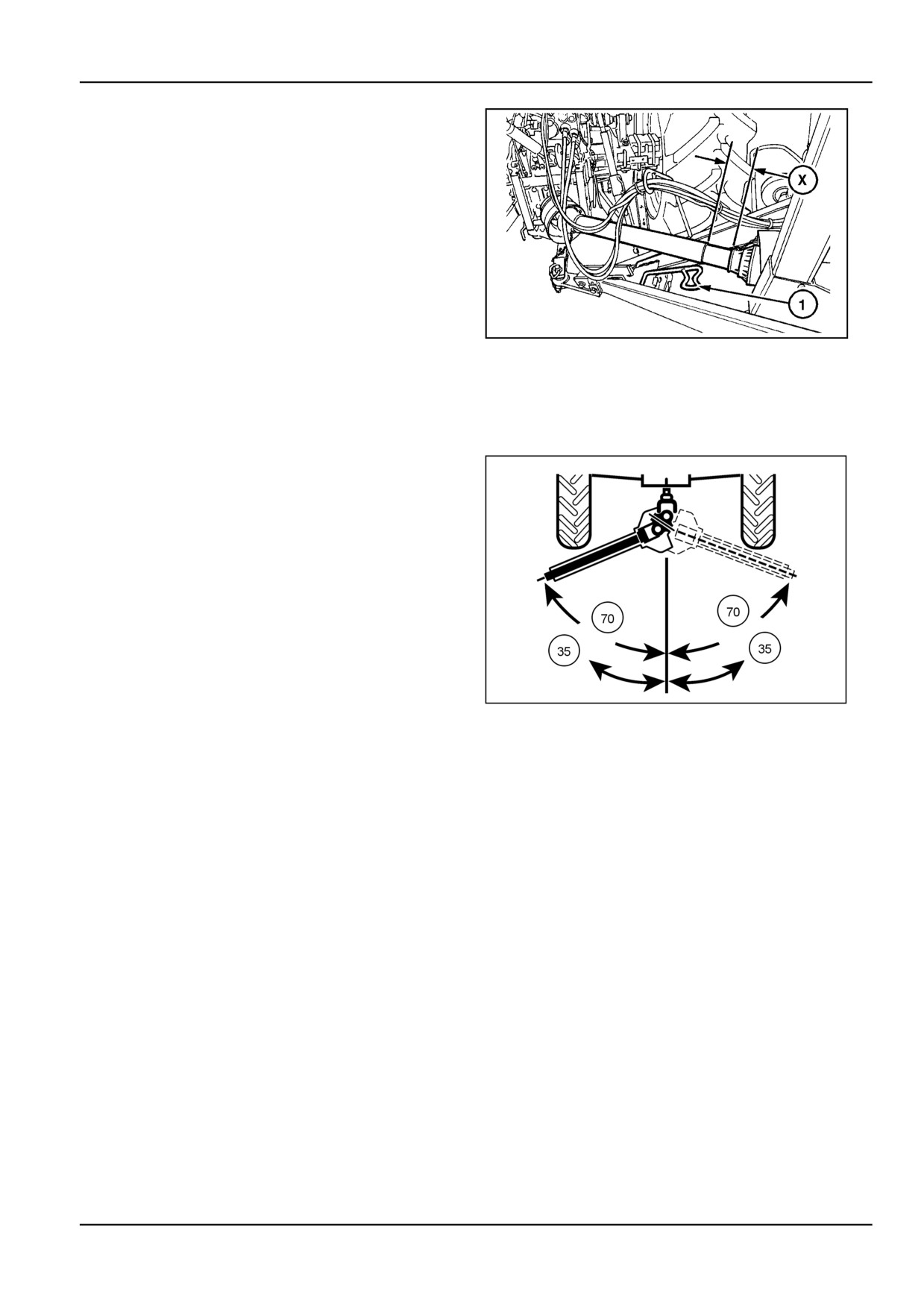
If distance (X) gets below 20 mm, either:
•
Increase the tractor drawbar length (e.g. from 35
cm to 41 cm) in case the baler tongue is fitted in
the low position and attached to the tractor swinging
drawbar.
OR
•
Shorten the PTO shaft in case the baler is fitted in
the high position and attached to the tractor rear tow
hook, see next paragraph.
Check for possible interferences with baler tongue com-
ponents, hydraulic hoses and electric cables.
ZIL10FCRB097AAA
20
NOTE: It is preferable to have a positive limitation on
the turning angle (i.e. tires contacting the baler tongue),
rather than having the possibility to exceed the PTO shaft
design capabilities. To avoid interferences and excessive
PTO angles, attach the baler closer to the tractor.
NOTICE: Disengage the tractor PTO when making ex-
tremely tight turns.
Restrict the PTO angle to:
•
Maximum 70 ° when disengaged or running idle.
•
Maximum 35 ° for continuous operation under heavy
load.
3571
21
4 - 11
4 - OPERATING INSTRUCTIONS
Shortening the PTO shaft - high hitch posi-
tion
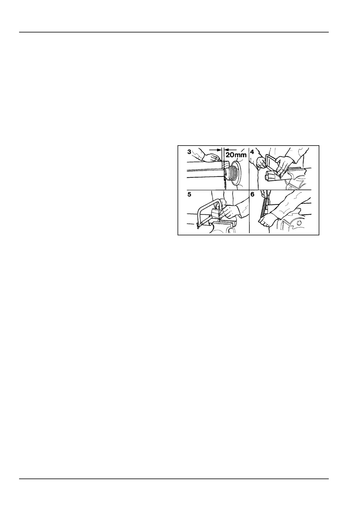
Should the PTO shaft need shortening, proceed as fol-
lows:
1.
Remove the front half of the PTO shaft from the
baler.
Place the rear half in the PTO support.
2.
Attach the baler to the tractor and make the sharpest
possible turn left or right as illustrated in Figure 19
and Figure 20.
Shut the tractor down. Attach the front half of the
PTO shaft to the tractor.
3.
Hold both PTO halves alongside each other and
mark the length to be cut off the front half guard.
4.
Cut the plastic guard.
5.
Cut the telescoping tube by the same amount as the
guard.
6.
File down sharp edges from the tube, remove any
swarf and thoroughly grease the telescoping tube.
7.
Also shorten the rear half guard and tube by the
same amount.
Further modifications to the PTO shaft and guards
are not allowed.
ZIL10FCRB112AAA
22
4 - 12
4 - OPERATING INSTRUCTIONS
Hydraulic connections [25663731]
Hydraulic system
WARNING
Pressurized hydraulic fluid can penetrate the
skin and cause severe injuries.
Tighten all of the connections before starting
the engine. If hydraulic fluid has penetrated
the skin, seek medical assistance immedi-
ately.
Failure to comply could result in death or se-
rious injury.
W0117A
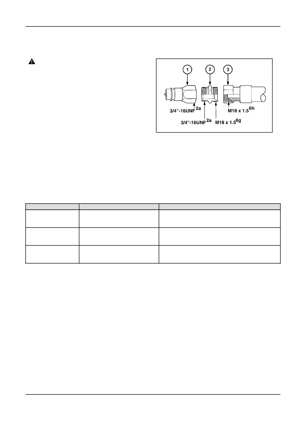
1.
The supply hoses (3) on the baler to operate the tail-
gate and the hydraulic pickup lift have a tractor-end
male coupler (1) complying with FIEI standard di-
ZIL10FCRB143AAA
1
mensions.
An adaptor (2) joins the hose to the coupler. This
coupler will fit most of our tractors, as well as the
majority of other brands of tractors. If this is not
the case, obtain the appropriate quick-coupler for
the tractor that will be used, and possibly another
adaptor that will fit the hose (3).
Install the couplers using Teflon tape or a similar
material on the threads to prevent joint leakage.
Couplers are provided with a colored cap for suggested usage:
Color
Function
Control Valve
Green
Pick-up (where fitted)
Single acting.
If using Double acting valve - connect at lift port to
operate and use float to lower and relieve pressure
Blue
Tailgate
Single acting.
If using Double acting valve - connect at lift port to
operate and use float to lower and relieve pressure
Black, Red
Rotor reverser (where fitted)
Single acting.
If using Double acting valve - connect at lift port to
operate and use float to lower and relieve pressure
ATTENTION: Check with your tractor dealer to be certain
your tractor hydraulic fluid is compatible with the baler oil.
If there is any question about the oil compatibility, purge
all oil from the baler hydraulic system, otherwise damage
to the tractor hydraulic system could result.
NOTE: The tailgate and rotor reverser supply hoses and
cylinders contain approximately 1 l of oil.
Keep the hose ends and fittings free from contamination
during installation and hook up, or damage to the tractor
and/or baler hydraulic system may result.
4 - 13

4 - OPERATING INSTRUCTIONS
2.
Securely install the hydraulic hose quick-disconnect
couplings (1) into the tractor remote control hy-
draulic outlets so the baler tailgate and pickup will
function properly in both directions.
Raise and lower the tailgate several times with the
tractor hydraulics. This will purge air from the hy-
draulic system and fill the system with oil.
NOTE: As the baler will retain a portion of the hy-
draulic oil from the tractor, check the tractor hy-
draulic system for correct oil level after purging and
add oil if necessary.
3.
Check all hose and tubing connections for hydraulic
leaks and tighten where necessary.
20021693
2
4.
Make sure the hydraulic lines do not rub the PTO.
and there is enough slack to permit sharp turns.
4 - 14
4 - OPERATING INSTRUCTIONS
Pick up [25766056]
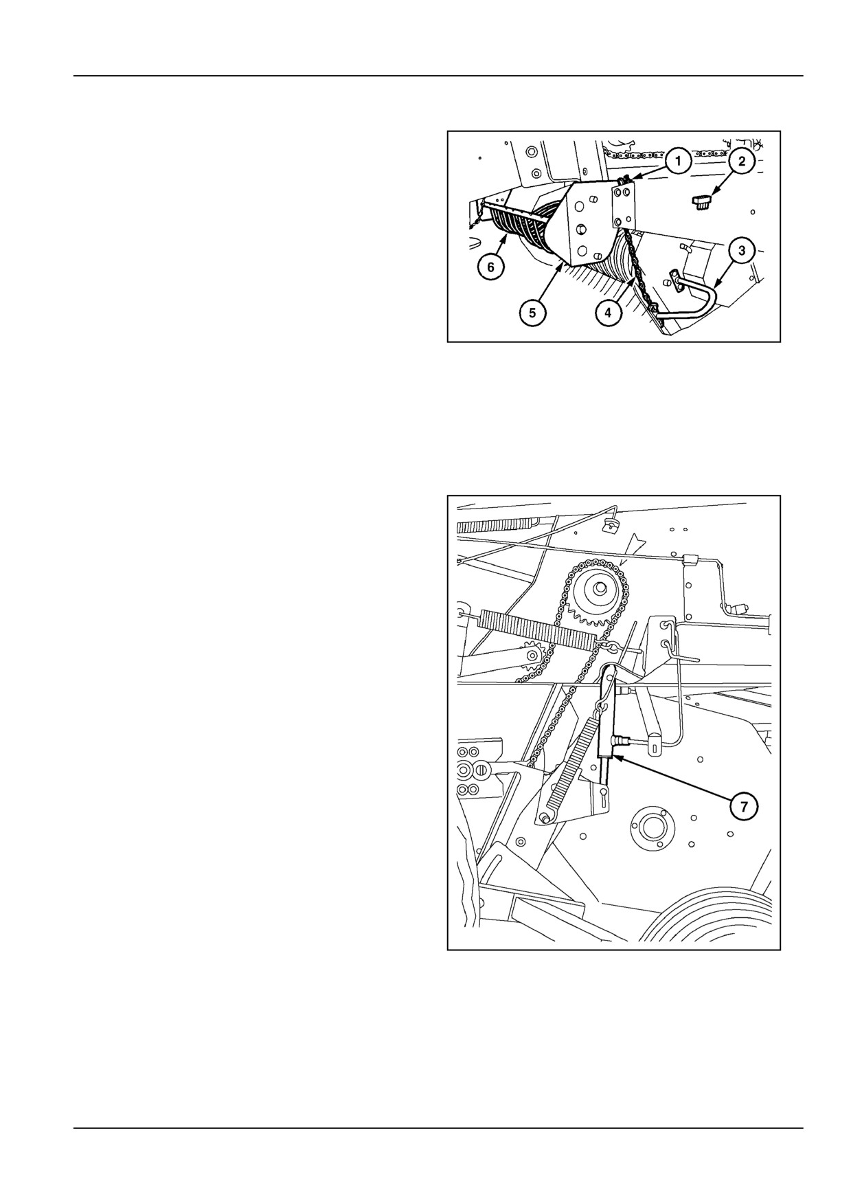
A pickup suspension chain is provided to:
•
Carry the pickup off the ground during transport on
the ground.
•
Adjust the pickup height on machines without pickup
wheels, the pickup wheel kit is an accessory.
•
Work with the pickup wheels off the ground in rough
fields.
To bring the pickup in the desired position, proceed as
follows:
1.
Grab the lift handle (3) and lift the pickup manually.
ZIL10FCRB752AAA
1
2.
Engage the suspension chain (4) in the notch (1) in
the frame.
The quick-attach floating windguard (6) can be re-
located in two positions in plate (5) to suit different
windrow sizes.
NOTE: Spare pickup drive line shear bolts are located at
(2).
The pickup hydraulic lift control (7) Figure 2 is available
as an accessory.
ZIL10FCRB012BAA
2
Guards removed for clarity
4 - 15
4 - OPERATING INSTRUCTIONS
Wide pickup
Pickup lift control
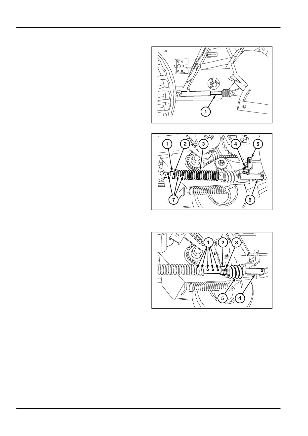
The pickup can be lifted and lowered hydraulically from
the tractor by means of the cylinder (1).
ZIL10FCRB753AAA
3
Pickup flotation
The pickup flotation rod serves several functions:
•
Figure 4: Pickup float position for field operation,
requiring the pickup wheels to run on the ground.
The rear pin (4) is removed from the rod and installed
on the support (5). The front collar (1) is locked with the
front pin (2) in one of the normal flotation holes (7) in the
flotation rod (6). The weight of the pickup is carried by the
spring (3) together with the pickup wheels.
ZIL10FCRB754AAA
4
Guards removed for clarity
•
Pickup fixed height position for operation in rough
or high stubble fields, requiring the pickup wheels to
be lifted off the ground.
The rear pin (3) secures the rear collar (2) in one of the
fixed height position holes (1) in the flotation rod (4). The
weight of the pickup is completely carried by the rear
spring (5). The front spring, collar and pin are free of
strain. To install the pin in the fixed height position, the
pickup must first be lifted with the tractor hydraulics.
•
Pickup transport position.
The rear pin secures the rear collar in the transport posi-
ZIL10FCRB755AAA
5
tion hole of the flotation rod. The weight of the pickup
is carried by the rear spring. To install the pin in the
Guards removed for clarity
pickup transport position, the pickup must first be lifted
completely with the tractor hydraulics.
4 - 16
4 - OPERATING INSTRUCTIONS
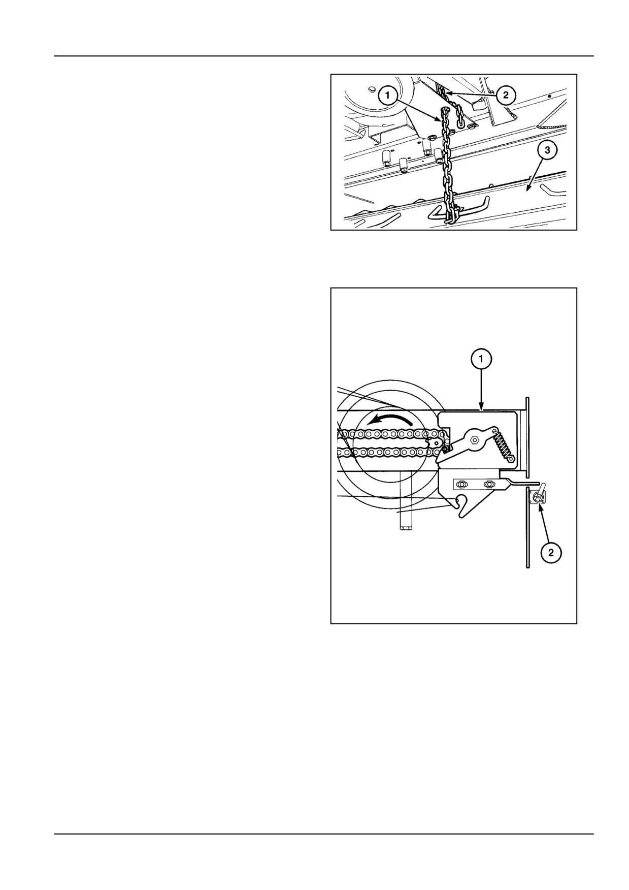
Baffle plate control
The pickup baffle plate (3) holds the crop in contact with
the pickup tines for positive feeding.
It is adjustable in height with the chain (1) to suit the vol-
ume of the windrow. A hook (2) is provided on the frame
to attach the chain.
ZIL10FCRB828AAA
6
Bale counter [25779184]
The Twin Twine models are equipped with a mechanical
bale counter (2) on the frame right-hand side sheet.
Every time a wrap cycle takes place, the right-hand twine
spreader (1) will increase the bale count by one.
The bale count can be reset to zero whenever wanted.
ZIL10FCRB010BAA
1
4 - 17
4 - OPERATING INSTRUCTIONS
Tailgate [25766723]
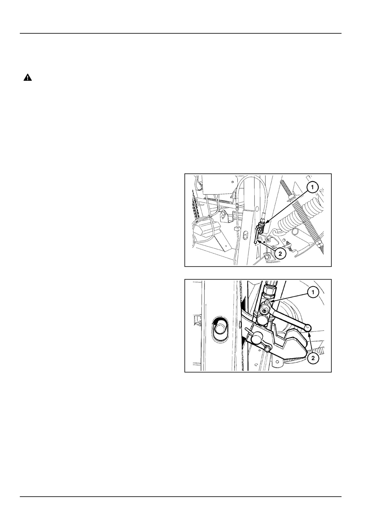
Lock out valve
DANGER
Crush hazard! The tailgate may close faster
than you can move away.
ALWAYS make sure the tailgate lockout valves
are in the OFF (locked) position before work-
ing under a raised tailgate. In the event of a
sudden loss of hydraulic pressure, the tailgate
will fall if the lockout valves are not engaged.
Stand clear of the tailgate before disengaging
the lockout valves.
Failure to comply will result in death or serious
injury.
D0002A
The tailgate lock out valve allows the operator to lock the
tailgate in any position to allow for easy access for servic-
ing. An instructional decal for valve control is located on
the valve body.
With the handle in position (1), the valve is closed, in the
position (2), the valve is open for normal operation.
ZIL10FCRB260AAA
1
With the handle in position (1) the lock is closed, in the
position (2), the valve is open for normal operation.
ZIL10FCRB079AAA
2
4 - 18