New Holland 667TA/EEG, 667TA/EEC, 667TA/EBF, 667TA/EED, 667TA/EBJ, 667TA/EDJ. ENGINE REPAIR MANUAL (2006) - page 3
ENGINE REPAIR MANUAL
CHAPTER 2 - 667TA ENGINE OVERHAUL
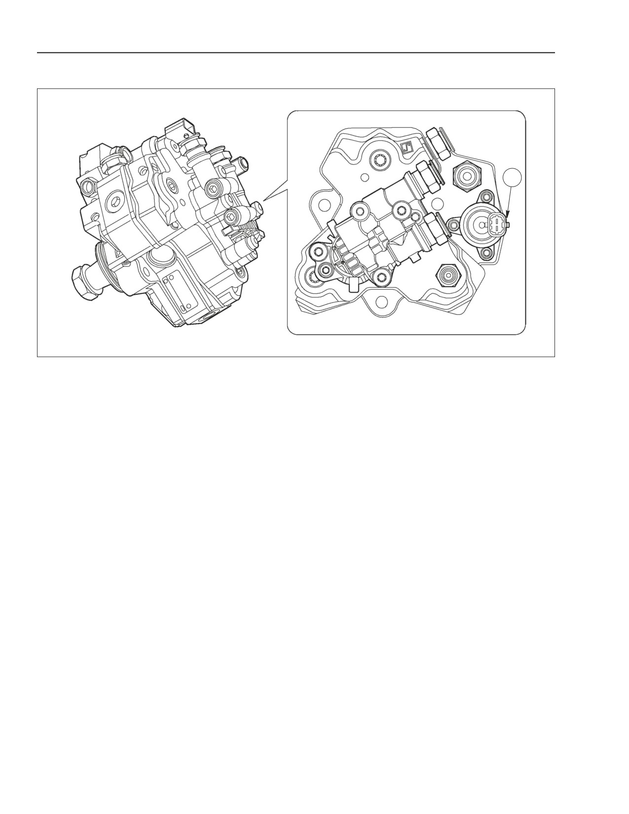
HIGH PRESSURE PUMP - PRESSURE REGULATOR
A
BS06K212
Figure 2-86
A. PRESSURE REGULATOR
Delivery pressure to the common rail is modulated
The quantity of fuel supplied to the high pressure
between 250 and 1600 bar (3626 and 23206 psi) by
pump is controlled by the supply pressure regulator
the EDC7UC31 control unit by controlling the high
solenoid valve. The high pressure regulator is
pressure regulator solenoid valve.
controlled by the EDC7UC31 control unit.
• This component is a Normally Open solenoid
valve.
• The solenoid is connected to the EDC7UC31
control unit on pins 9A - 10A.
• The solenoid valve impedance is approximately
3.2 ohms.
2-66
Issued 11-06
Bur
87519804 NA
ENGINE REPAIR MANUAL
CHAPTER 2 - 667TA ENGINE OVERHAUL
CHECKING THE FUEL SYSTEM
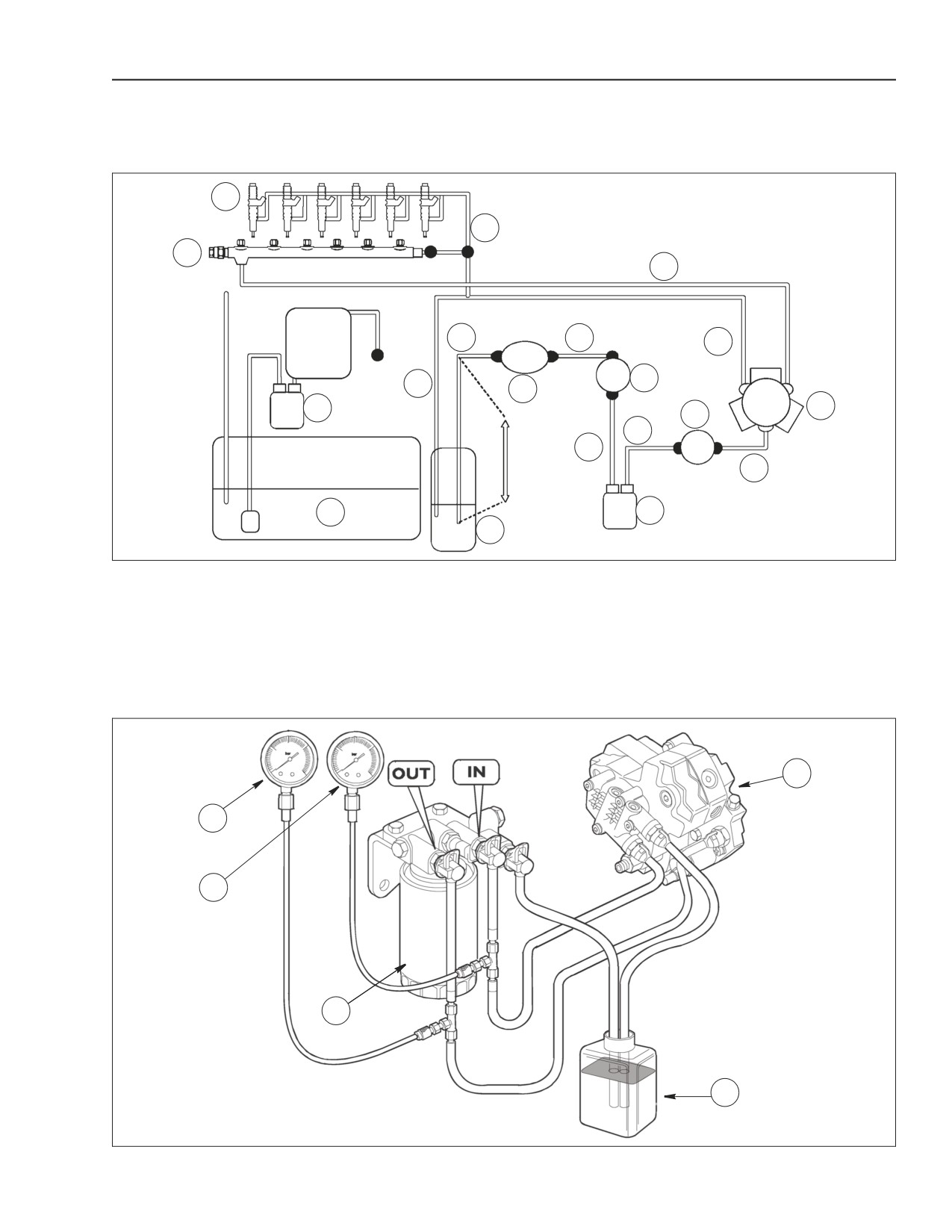
LOW PRESSURE SUPPLY TEST
10
9
8
7
4
4
9
11
9
3
2
6
12
4
4
4
1
5
13
BS06K214
Figure 2-87
DIAGRAM OF SET UP OF COMPONENTS FOR SPECIFIC TEST
1. FUEL TANK
6. HIGH PRESSURE PUMP
11. M1 PRESSURE GAUGE 0-15 BAR FUEL FILTER INLET
2. PREFILTER
7. HIGH PRESSURE CIRCUIT
12. M2 PRESSURE GAUGE FUEL FILTER OUTLET
3. LOW-PRESSURE PUMP
8. COMMON RAIL
13. EXTERNAL CONTAINER PLACED 1M (39 IN) BELOW ENGINE
4. FUEL DELIVERY CIRCUIT
9. FUEL RECIRCULATION
5. FUEL FILTER
10. INJECTORS
6
12
11
5
13
BS06K215
Figure 2-88
87519804 NA
Issued 11-06
Bur
2-67
ENGINE REPAIR MANUAL
CHAPTER 2 - 667TA ENGINE OVERHAUL
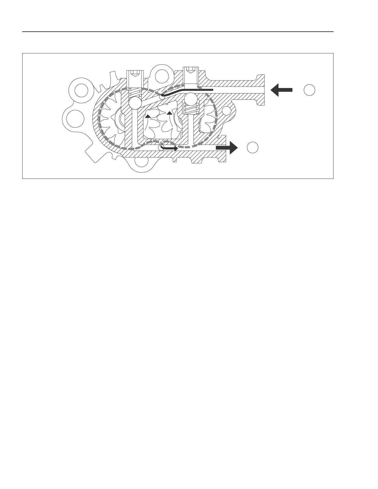
LOW -PRESSURE PUMP
A
B
BS06K216
Figure 2-89
The function of the gear pump is to supply the high
After starting the engine, check the pressure at 1500
pressure pump. It is driven by the shaft of the high
rpm.
pressure pump and is installed on the rear portion of
On pressure gauge M1- (11) it must be between 6
the high pressure pump.
and 9 bar (87 and 130 psi.)
Under normal operating conditions, the flow of fuel
• If lower than 6 bar (87 psi.) replace pump
inside the pump is as shown in the figure above.
• If higher than 9 bar (130 psi.) replace the fuel
filter.
With the fuel system pressurized, a fully charged
battery and an external fuel supply placed 1m (39 in.)
On pressure gauge M2- (12) it must be greater than
below the engine. The engine must start within 20
5 bar (72.5 psi.)
seconds of activation of the starter motor. If the pump
• If lower, replace the fuel filter
is not able to draw fuel to the engine and start the
• If the trouble persists, check the seals on the
engine the low pressure pump is probably defective.
couplings of the fuel filter bracket and the high
pressure pump inlet.
2-68
Issued 11-06
Bur
87519804 NA
ENGINE REPAIR MANUAL
CHAPTER 2 - 667TA ENGINE OVERHAUL
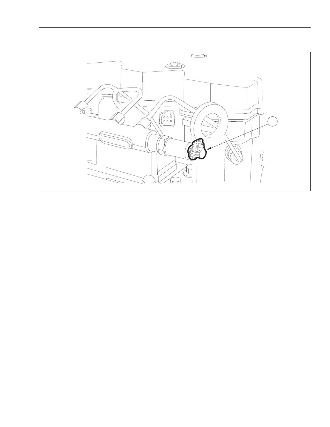
TEST ON THE PRESSURE RELIEF VALVE ON
THE COMMON RAIL
1
BS06K217
Figure 2-90
The pressure relief valve is installed on the end of the
If the valve seeps diesel without a fault code, then
common rail, its function is to protect the systems
replace the valve.
components if any malfunction causes and excessive
With the common rail pressure sensor disconnected
increase in the pressure of the high pressure system.
and a fault code is generated, with the rail pressure is
Disconnect recirculation line (1) from the pressure
at 710 bar (10298 psi.) measurable with the
relief valve and plug with the VOSS fitting from the
diagnostic instrument, the trouble is in the wiring and
test set.
not the component.
No diesel must come out of the valve at any engine
speed. If the diagnostic system signals a fault code
“Engine - backfill valve control”, it means that the
EDC7UC31 control unit has recognized that the
value has opened after a significant change in the
pressure of the rail greater than 1700 bar (24656
psi.). Since its opening is to be considered a
consequence of abnormal increase in pressure, the
valve is NOT defective even though a great amount
of diesel flows out.
IMPORTANT: Information acquired to date shows that the sensor is rarely defective.
87519804 NA
Issued 11-06
Bur
2-69
ENGINE REPAIR MANUAL
CHAPTER 2 - 667TA ENGINE OVERHAUL
TEST ON FUEL BACKFLOW FROM THE RETURN
1
BS06K219
Figure 2-92
BS06K218
Figure 2-91
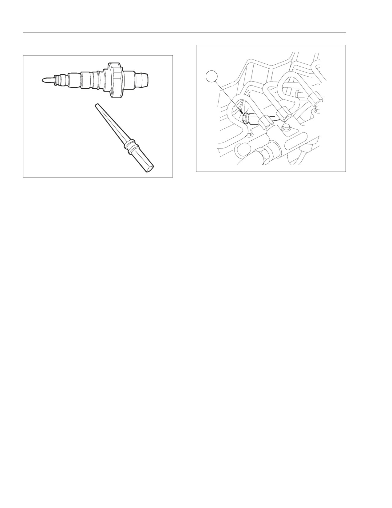
1. INJECTOR DUCT LOCKING NUT
Tests on fuel backflow from the return establishes
When the EDC7UC31 control unit warning light
the operating status of the injectors. The engine
comes on during acceleration and/or cold start
speed and power are controlled through the
trouble, make sure the following check is done.
injectors. The power required by the user, through
• Check torque of the nut (1) locking the injector
the accelerator, is converted into the quantity of fuel
duct on the cylinder head. The torque setting is
injected per cycle. This in turn is converted into
45 - 55 Nm (33.2 - 40.6 lb.- ft.).
microseconds of injector opening according to the
rail pressure.
NOTE: The injectors may have problems of both a
mechanical and a electrical nature. Therefore before
proceeding with the following analysis, it is wise to
rule out the presence of water in the tank and the fuel
prefilter.
2-70
Issued 11-06
Bur
87519804 NA
ENGINE REPAIR MANUAL
CHAPTER 2 - 667TA ENGINE OVERHAUL
3
4
2
1
BS06K220
Figure 2-93
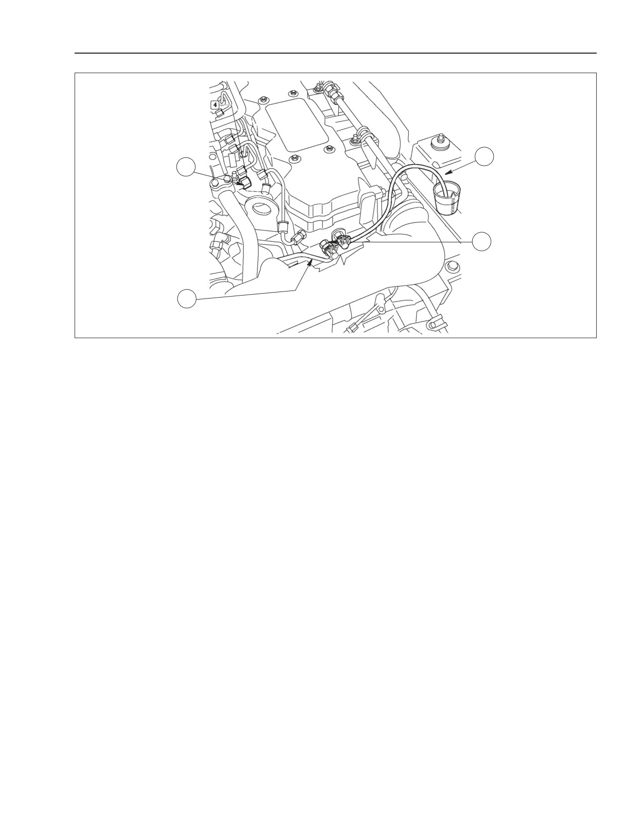
Proceed with the injector fuel backflow tests as
The defective injector is the one when plugged
follows:
causes a significant reduction in recirculated fuel.
• Remove the duct (1) from the cylinder head.
NOTE: When changing an injector it is necessary to
• Plug it (2)
change the duct.
• Install a transparent line (3)
After identifying the injectors / ducts with high fuel
Make sure that the engine idling speed is correct.
recirculation, check the torque of the ducts, 45 - 55
Check the quantity of fuel recirculation from the
Nm (33.2 - 40.6 lb.- ft), if they are loose tighten. Then
cylinder head.
check the recirculation values again.
The process for measuring the quantity of injector
If the torque is correct, remove the line and check the
return fuel is:
spherical end towards the injector is not out of round,
• Engine idling and without air compressor or air
replace if necessary. Recheck recirculation value.
conditioner on.
If the duct is not out of shape, replace the injector
• engine temperature greater than 50°C (122°F).
and duct. Check the recirculation value again.
The quantity of fuel that flows out must be no greater
than 80ml. (2.7 oz.) of diesel per minute. Excessive
recirculation more than 80ml. (2.7 oz.) of diesel per
minute could be caused by:
• Incorrect coupling between one or more
injectors and the related needles.
• Problem of internal leakage of the injector.
To identify the defective injector, follow the method
as described below:
Measure the quantity of fuel flowing out in one
minute from the coupling on the cylinder head. If
recirculation exceeds 80 ml. (2.7 oz.) per minute,
plug the rail outlet of one injector (4) at a time using
the rail plugs in the test set.
87519804 NA
Issued 11-06
Bur
2-71
ENGINE REPAIR MANUAL
CHAPTER 2 - 667TA ENGINE OVERHAUL
ENGINE OVERHAUL ON THE BENCH
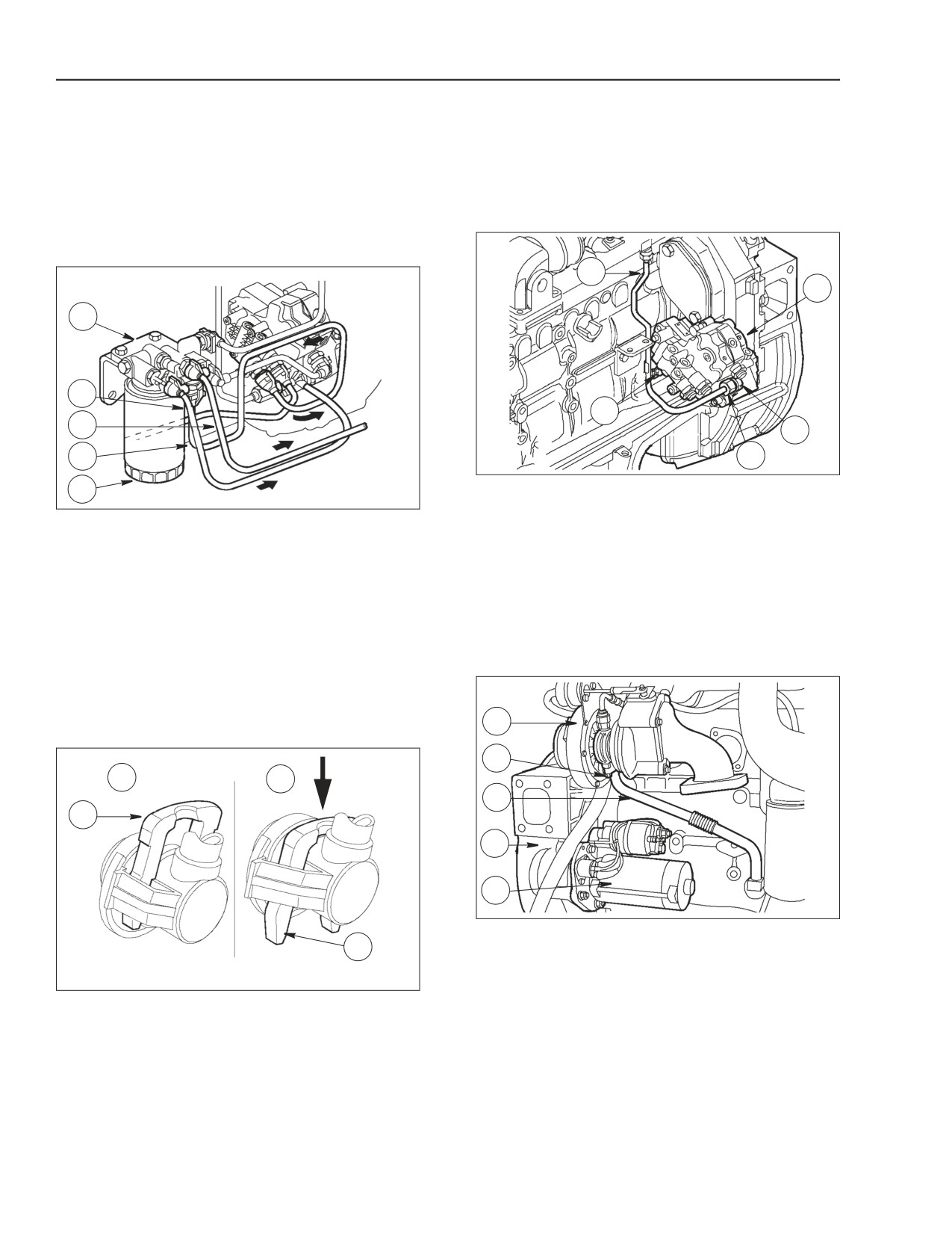
IMPORTANT: Push clamp (1), as shown in figure B
to disconnect the low pressure fuel lines (2, 3, 4)
DISASSEMBLING THE ENGINE
from the corresponding connections. After
disconnecting the line, reset the clamp (1) in locking
STEP 1
position figure A to prevent distortion to the clamp.
Drain the engine oil by removing the plug from the oil
pan (sump).
STEP 4
STEP 2
1
5
1
2
2
3
4
4
3
BS06K223
Figure 2-96
5
Disconnect fuel line (1) from common rail and from
BS06K221
Figure 2-94
high pressure pump (5) and remove it by taking out
Apply the brackets for fastening the engine to the
securing bolts (2).
engine stand as follows (working from the left side of
IMPORTANT: When loosing fitting (3) of fuel line (1),
the engine.
it is necessary to use a suitable wrench to prevent
• Use a suitable tool to remove the fuel filter (5) from
fitting (4) of high pressure pump (5) from rotating.
the fuel filter bracket (1).
• Disconnect the low pressure lines (2, 3, 4) from
STEP 5
the fuel filter bracket (1).
From the Right Side:
• Remove the fuel filter bracket (1) from the engine
block.
1
STEP 3
2
A
B
3
1
4
5
BS06K224
Figure 2-97
1
Remove the mounting bolts (2) and remove the oil
line (3) from the Turbo-charger (1) from the engine
block.
BS06K222
Figure 2-95
Remove the starter (5) from the flywheel housing (4)
Secure the engine to a engine stand.
2-72
Issued 11-06
Bur
87519804 NA
ENGINE REPAIR MANUAL
CHAPTER 2 - 667TA ENGINE OVERHAUL
STEP 6
1
6
2
7
3
8
4
9
10
11
5
BS06K225
Figure 2-98
9.
FUEL HEATER- TEMPERATURE
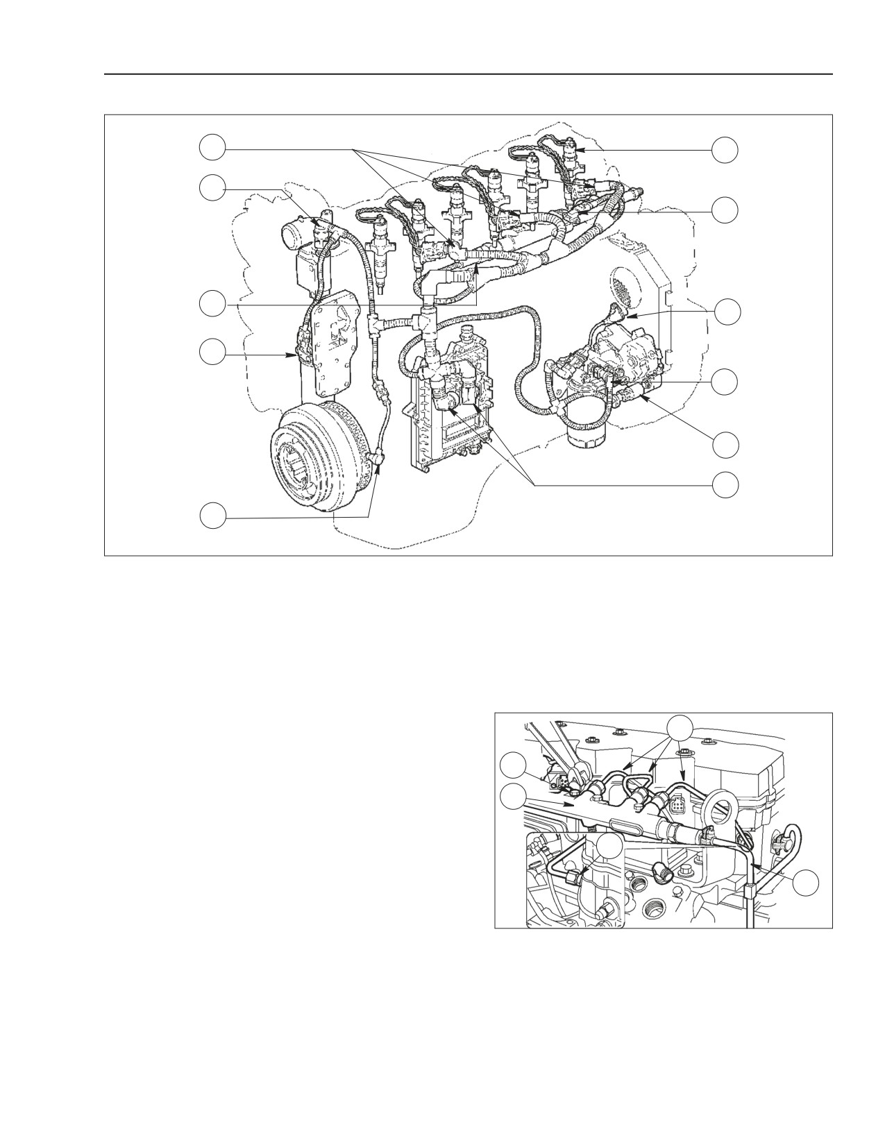
1. INJECTOR CONNECTIONS
5. CRANKSHAFT SPEED SENSOR
SENSOR
2. ENGINE COOLANT TEMPERATURE SENSOR
6. INJECTOR
10.
HIGH PRESSURE REGULATOR
7. BOOST TEMPERATURE-PRESSURE
3. COMMON RAIL FUEL PRESSURE SENSOR
11.
EDC7UC31 CONTROL UNIT
SENSOR
4. OIL TEMPERATURE- PRESSURE SENSOR
8. CAMSHAFT SENSOR
Disconnect the engine cable by disconnecting the
STEP 7
following connectors:
5
• Connectors (1) from injector wiring (6)
• Engine coolant temperature sensor on the
1
thermostat (2)
• Common rail fuel pressure sensor (3)
2
• Crankshaft speed sensor (5)
• Boost pressure / temperature sensor (7)
3
• Camshaft sensor (8)
4
• High pressure regulator (10)
• EDC7UC31 control unit (11)
BS06K226
Figure 2-99
Disconnect from the common rail (2):
• Fuel line (4) according to procedure on step 3
page 2-72
• Fuel lines (5)
• Injector manifolds (3)
• Remove the bolts (1) and disconnect the common
rail (2)
87519804 NA
Issued 11-06
Bur
2-73
ENGINE REPAIR MANUAL
CHAPTER 2 - 667TA ENGINE OVERHAUL
STEP 8
STEP 10
1
1
2
2
3
5
4
5
6
4
7
3
8
BS06K229
Figure 2-102
BS06K227
Figure 2-100
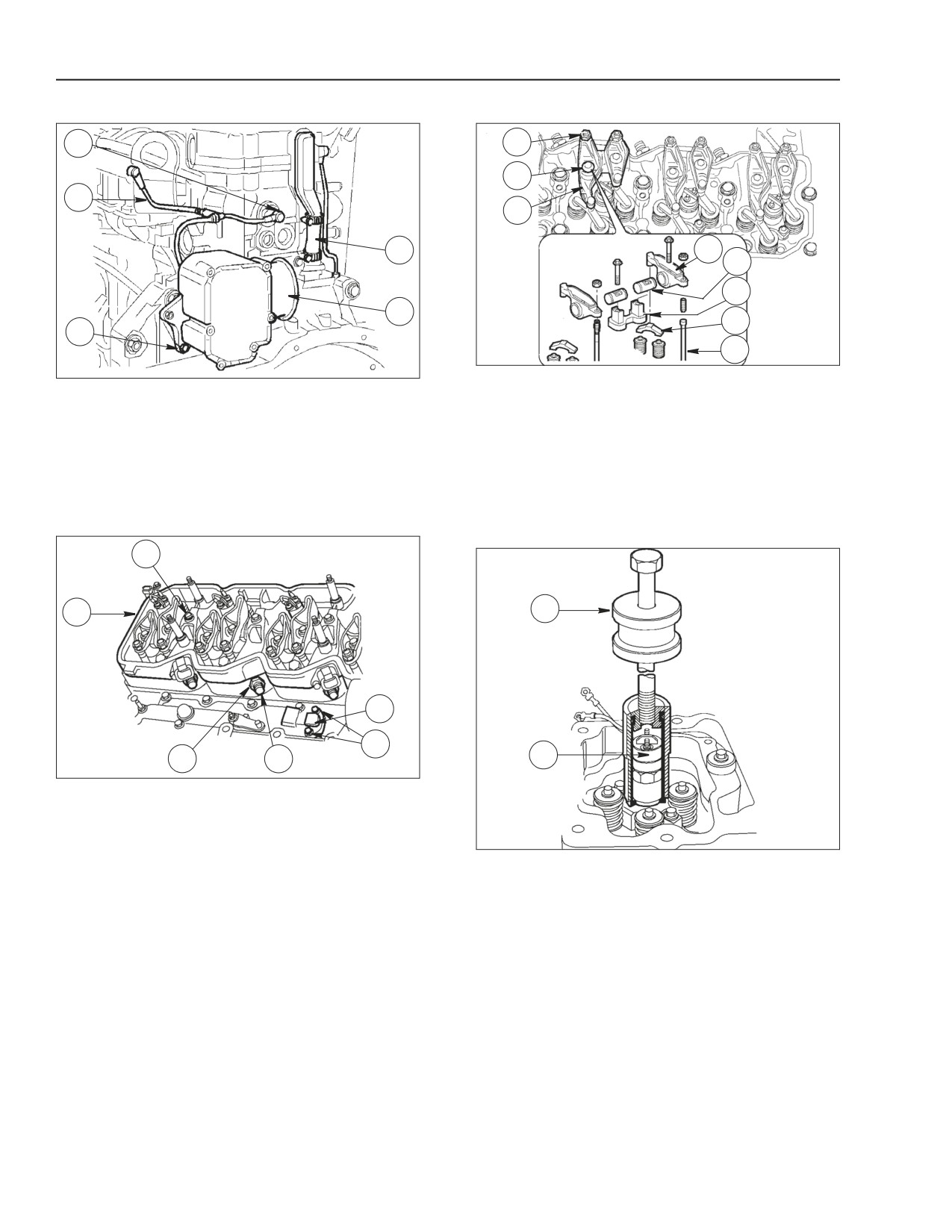
Loosen tappet adjusting nuts (1) and unscrew the
Disconnect line (2) from fuel return pressure limiter
adjusters.
(1) as shown in step 3 page 2-72.
Remove the bolts (2), remove the rocker assembly
Remove the nut, loosen the retainer collar and
(3), consisting of bracket (6), rockers (4), shafts (5)
disconnect the oil vapor line (5). Remove bolts (3)
and remove jumpers (7) from valves. Remove rods
and take off the blow-by filter (4).
(8).
STEP 9
STEP 11
1
2
1
6
5
3
4
2
BS06K228
Figure 2-101
Remove nuts and remove the tappet cover including
the gasket.
Remove bolts (1) and disconnect the injector wiring
BS06K230
Figure 2-103
housing (2) complete with gasket.
Remove injector fastening bolts. Use Special Tool
Remove bolts (5) and detach the boost temperature/
380001099 (1) to remove injectors (2) from the
pressure sensor (6).
cylinder head.
Remove nuts (3) and remove the fuel inlet
connectors (4).
IMPORTANT: Disassembled fuel inlet connectors (4)
must not be used again. They must be replaced with
new ones.
2-74
Issued 11-06
Bur
87519804 NA
ENGINE REPAIR MANUAL
CHAPTER 2 - 667TA ENGINE OVERHAUL
STEP 12
STEP 14
5
3
1
4
2
4
5
6
3
1
2
BS06K231
Figure 2-104
BS06K233
Figure 2-106
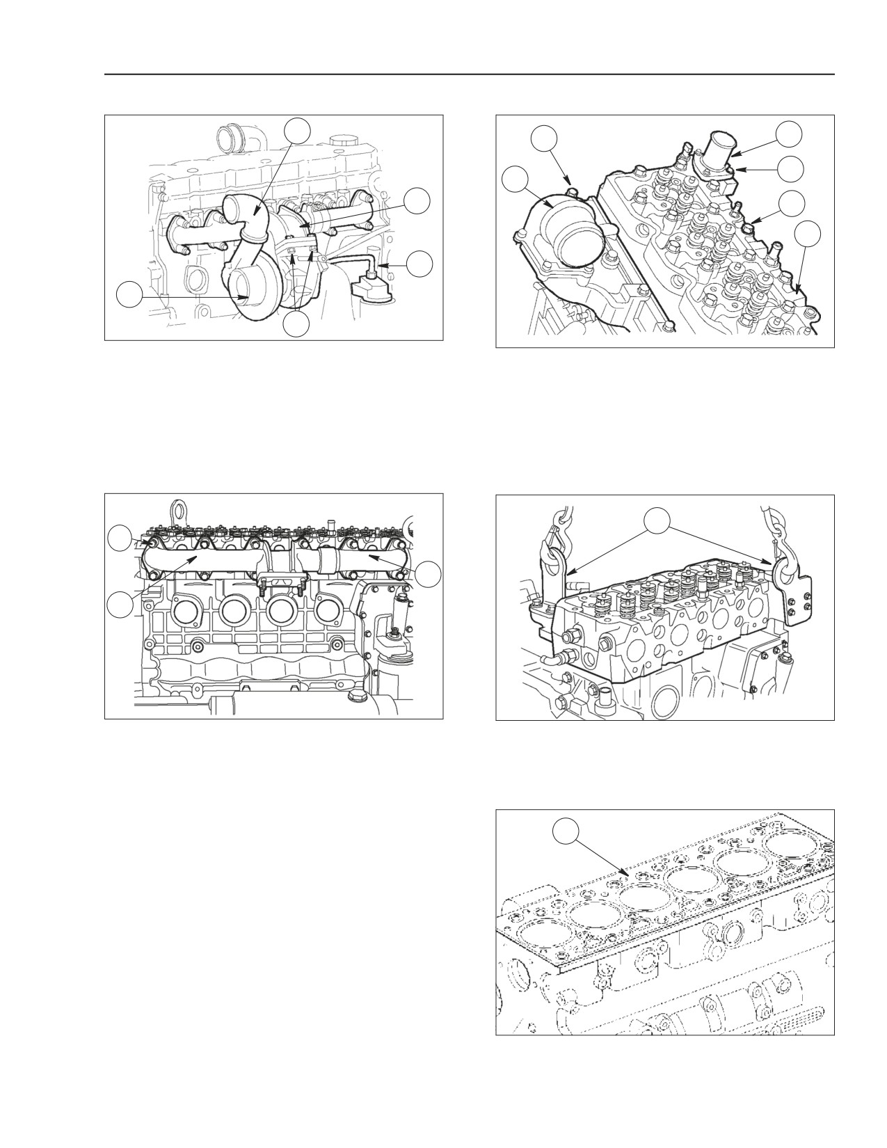
Remove shroud (5), if present from turbocharger (1).
Remove bolts (1) and disconnect intake manifold and
Disconnect oil line (3) from heat exchanger oil filter
heater air shroud (2). Remove the bolts (4), and take
bracket.
off the thermostat housing (3) and the thermostat
under the housing.
Remove nuts (2) and detach turbocharger (1) from
exhaust manifold (4).
Remove the cylinder head (6), fastening bolts(5).
STEP 13
STEP 15
1
1
3
2
BS06K232
Figure 2-105
BS06K234
Figure 2-107
Remove securing bolts (1) and remove exhaust
Attach brackets (1) to cylinder head and remove
manifold in two sections (2 and 3) with related
cylinder head from block using a hoist.
gaskets.
STEP 16
1
BS06K235
Figure 2-108
Remove cylinder head gasket (1).
87519804 NA
Issued 11-06
Bur
2-75
ENGINE REPAIR MANUAL
CHAPTER 2 - 667TA ENGINE OVERHAUL
STEP 17
STEP 19
2
1
1
3
BS06K236
Figure 2-109
BS06K238
Figure 2-111
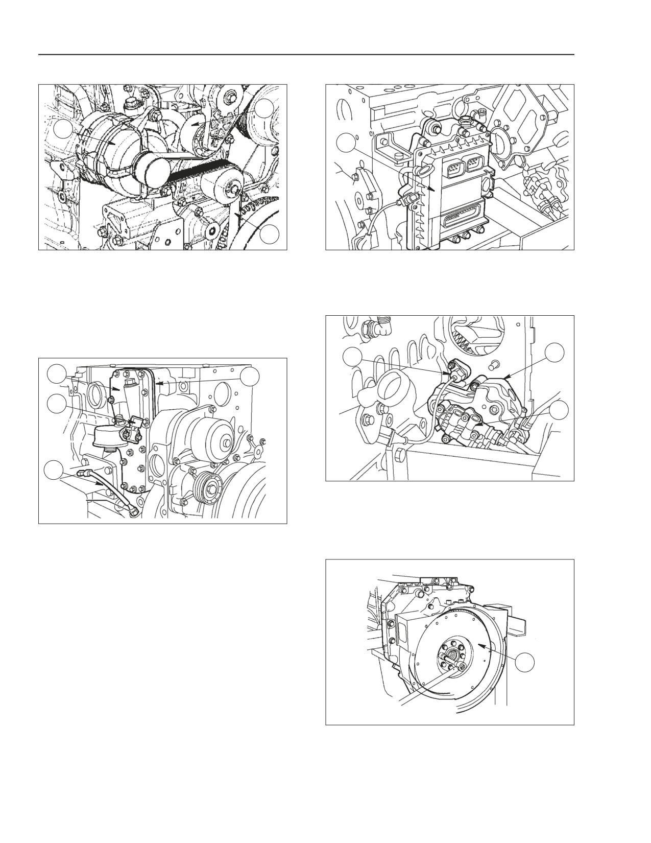
Release the drive belt tensioner (2) and remove the
Remove the bolts and disconnect the EDC7UC31
belt (3) from the pulleys. Then remove the belt
control unit (1), including the heat exchanger.
tensioner (2).
STEP 20
Loosen bolts holding the alternator to bracket and
remove the alternator (1).
STEP 18
3
1
1
4
2
2
3
BS06K239
Figure 2-112
Remove the nut and disconnect the timing sensor
(1). Remove the nuts and disconnect the high
BS06K237
pressure pump (3) including the feed pump (2).
Figure 2-110
Take out bolts and remove the oil temperature-
STEP 21
pressure sensor (2).
Take out bolts and then remove heat exchanger/ oil
filter bracket (1) and intermediate plate (4) and
relevant gaskets.
Remove the oil level sensor (3).
1
BS06K240
Figure 2-113
Loosen bolts on flywheel (1) but do not remove the
flywheel.
2-76
Issued 11-06
Bur
87519804 NA
ENGINE REPAIR MANUAL
CHAPTER 2 - 667TA ENGINE OVERHAUL
STEP 22
STEP 24
A
B
1
2
1
2
3
4
3
BS06K241
Figure 2-114
BS06K243
Figure 2-116
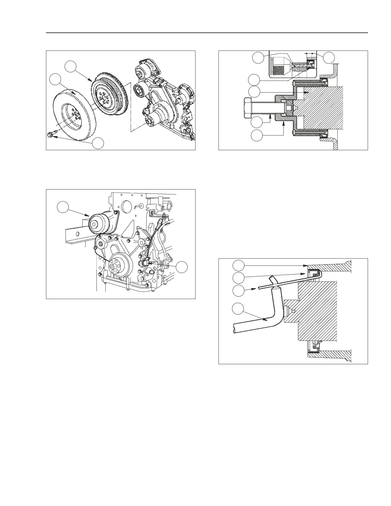
Remove the bolts (3) and take off the damping
Place Special Tool 380000665 (4) to the front of the
flywheel (2) and the pulley (1).
crankshaft (2).
Working through the guide holes of Special Tool
STEP 23
380000665 (4), drill into the internal seal ring (1) with
a 3.5mm
(9/64 in.) drill bit (A) to a depth of 5mm (3/16 in.) (B).
1
Secure Special Tool 3800000665 (4) to the ring (1)
by screwing down the six bolts supplied with tool to
the crankshaft front cover.
Now extract seal ring (1) by tightening bolt (3).
STEP 25
1
2
2
3
BS06K242
Figure 2-115
Remove the bolts and disconnect the water pump
4
(1). Remove the bolt and disconnect the engine
speed sensor (2).
BS06K244
Figure 2-117
Using the pry bar (3) and the lever (4), remove the
external seal ring (2) from the front cover (1).
87519804 NA
Issued 11-06
Bur
2-77
ENGINE REPAIR MANUAL
CHAPTER 2 - 667TA ENGINE OVERHAUL
STEP 26
STEP 29
\
1
2
1
3
BS06K245
Figure 2-118
BS06K248
Figure 2-121
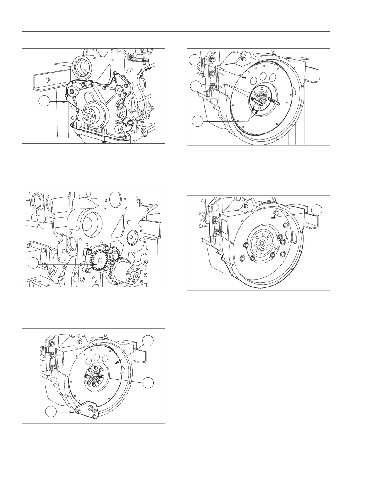
Remove the bolts and take off the front cover (1).
Screw two pins (2) of adequate length into the
IMPORTANT: Note the installation position of the
crankshaft holes (3).
bolts because they are different lengths.
Remove the flywheel (1) with a hoist.
STEP 27
STEP 30
1
1
BS06K246
Figure 2-119
BS06K249
Figure 2-122
Remove bolts and take off gear oil pump (1).
Remove bolts and take off rear cover (1).
IMPORTANT: Oil pump (1) can not be repaired.
IMPORTANT: Note the installation position of the
bolts because they are different lengths.
STEP 28
3
2
1
BS06K247ID
Figure 2-120
Remove tool (1) remove bolts securing flywheel (3)
to crankshaft (2).
2-78
Issued 11-06
Bur
87519804 NA
ENGINE REPAIR MANUAL
CHAPTER 2 - 667TA ENGINE OVERHAUL
STEP 31
STEP 33
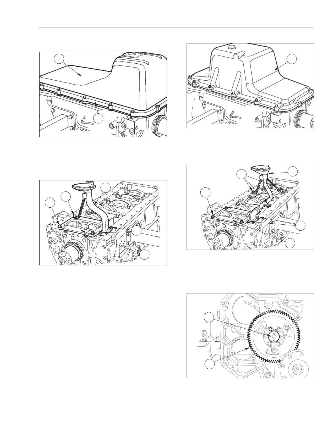
Turn engine upside down
1
1
2
BS06K252
Figure 2-125
BS06K250
Figure 2-123
NOTE: Only on engines 667TA/EED- /EBD.
NOTE: Only on engines 667TA/EEG- /EEC- /EBF-
Remove bolts and oil pan (sump) (1).
/EED- /EDJ.
STEP 34
Remove the bolts, plate (2) and oil pan (sump) (1).
5
STEP 32
1
5
2
1
2
4
4
3
BS06K253
Figure 2-126
3
NOTE: Only on engines 667TA/EED- /EBD.
BS06K251
Figure 2-124
Remove bolts (1 and 4) and remove oil suction tube
NOTE: Only on engines 667TA/EEG- /EEC- /EBF-
(5). Remove bolts (2) and remove stiffening plate (3).
/EED- /EDJ.
STEP 35
Remove the bolts (1 and 4) and remove the oil
suction tube (5). Remove the bolts (2) and remove
the stiffening plate (3).
1
2
BS06K254
Figure 2-127
Remove bolts and take gear (2) off of camshaft (1)
87519804 NA
Issued 11-06
Bur
2-79
ENGINE REPAIR MANUAL
CHAPTER 2 - 667TA ENGINE OVERHAUL
STEP 36
STEP 38
1
1
2
BS06K255
Figure 2-128
BS06K257
Figure 2-130
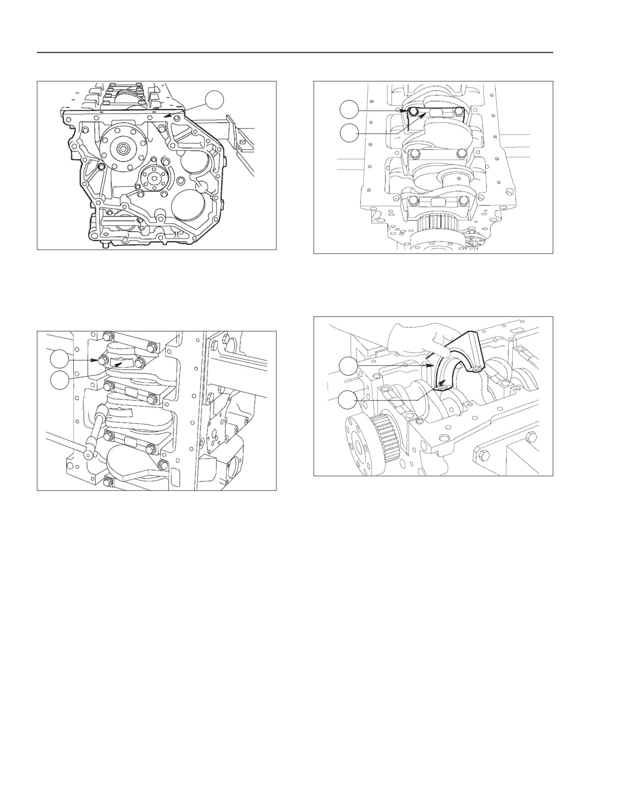
Remove bolts and take off timing gear case (1).
Remove bolts (1) and take off the main bearing
IMPORTANT: Note the installation position of the
journals(2).
bolts because they are different lengths.
STEP 39
STEP 37
1
1
2
2
BS06K258
Figure 2-131
BS06K256
Figure 2-129
The main bearing journal cap (1) and its respective
Remove bolts (1), then take off connecting rod caps
thrush bearing (2) have a shoulder to control
(2).
crankshaft endplay.
Remove the pistons (complete with connecting rods)
IMPORTANT: Take note of the mounting position of
from the crankcase.
the main bearings and thrush bearings: If they have
to be reused again, they must be installed in the
IMPORTANT: Half bearings must be kept in their
same position they had prior to being removed.
respective housings: If they have to be reused, they
must be installed in the same position they had prior
to being removed.
2-80
Issued 11-06
Bur
87519804 NA
ENGINE REPAIR MANUAL
CHAPTER 2 - 667TA ENGINE OVERHAUL
STEP 40
STEP 42
1
1
2
2
BS06K261
Figure 2-134
BS06K259
Figure 2-132
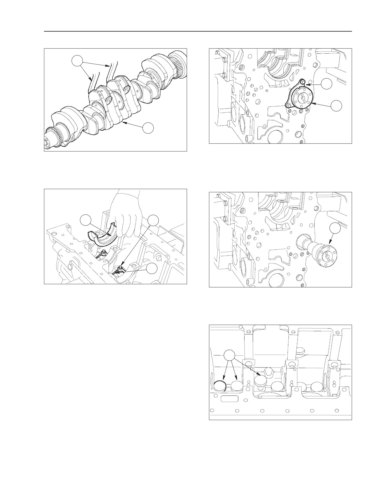
Remove bolts and take off camshaft (2), retaining
Remove crankshaft (2) from crankcase by means of
plate (1).
a suitable tool (1) and a hoist.
IMPORTANT: Note plate (1) mounting position.
STEP 41
STEP 43
1
2
1
3
BS06K260
Figure 2-133
BS06K262
Figure 2-135
Take off main half bearings (1).
Carefully remove camshaft (1) from engine
Remove bolts (2) and take off oil nozzles (3).
crankcase.
IMPORTANT: Take note of the mounting position of
STEP 44
the main bearings and thrush bearings: If they have
to be reused again, they must be installed in the
same position they had prior to being removed.
1
BS06K263
Figure 2-136
Remove tappets (1) from the engine crankcase.
87519804 NA
Issued 11-06
Bur
2-81
ENGINE REPAIR MANUAL
CHAPTER 2 - 667TA ENGINE OVERHAUL
CHECKS AND SPECIFICATIONS ON ENGINE CRANKCASE
CHECKS AND MEASUREMENTS
STEP 46
STEP 45
1
1
1
B
2
A
2
3
2
BS06K265
Figure 2-138
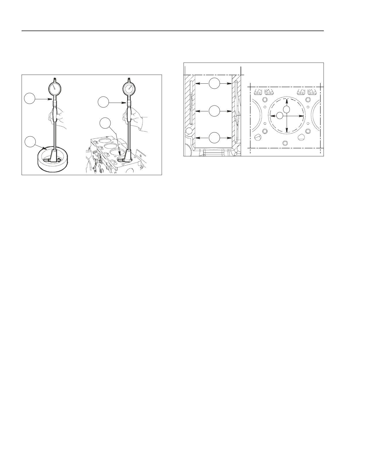
Measurements must be taken for each cylinder, at
three different heights (1,2,3) of the bore and on two
BS06K264
Figure 2-137
planes perpendicular to each other. One parallel to
After the engine has been disassembled, clean the
the engine longitudinal axis (A), the other
block thoroughly.
perpendicular (B), the greatest amount of wear is
Check the crankcase carefully for cracks. Check the
usually found on the (B) plane, and during the first
condition of freeze plugs. They must be replaced if
measurement. When detecting out-of-roundness,
they are rusty or their sealing properties are in doubt.
taper or wear, in the cylinder bore, they must be
Inspect the cylinder bore surfaces, they must not
bored and resurfaced. Cylinder bore reconditioning
show traces of seizing, scoring, out-of-roundness,
must be done in standard increments of over sized
taper or excessive wear.
pistons and rings.
Check the cylinder bore inner diameter (in order to
measure the amount of out-of-roundness, taper and
wear) a bore gauge (1) equipped with a dial indicator,
check the cylinder bore diameter (2).
IMPORTANT: If no ring gauge is available, use a
micrometer to perform the test.
2-82
Issued 11-06
Bur
87519804 NA
ENGINE REPAIR MANUAL
CHAPTER 2 - 667TA ENGINE OVERHAUL
CHECKING THE ECCENTRIC LIFT AND BEARING
BEARINGS
SURFACE
STEP 48
STEP 47
1
3
3
1
2
2
BS06K267
Figure 2-140
BS06K266
Figure 2-139
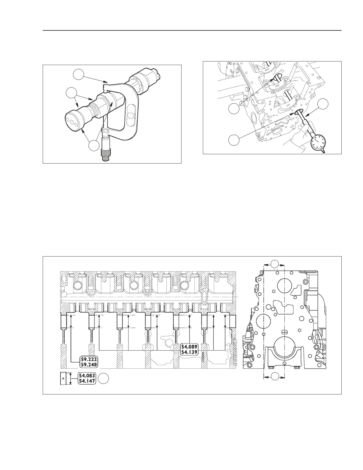
The camshaft bearings (2) must be force-fitted into
their respective seats.
Check camshaft with a micrometer (1) the bearing
surface (2) measurement must not have greater than
The inner surfaces must show no traces of seizing or
0.04 mm (0.0016 in.) of wear otherwise replace
wear.
camshaft. Also check the eccentric (lobe) lift (3),
Use a bore gauge (3) to measure the diameter of
which must be equal to 7.582 mm (0.2985 in.) for
front and rear bearings (2) and of camshaft
exhaust eccentric (lobes). And 6.045 mm (0.2380 in.)
intermediate seats (1).
for intake eccentrics (lobes). If different values are
Measurements must be taken on two axis
found than specifications replace the camshaft.
perpendicular to each other.
Check the diameter of camshaft support journals with
a micrometer (1) on two axis perpendicular to each
other.
A
A
B
BS06K268
Figure 2-141
MAIN FEATURES OF CAMSHAFT BEARINGS AND THEIR RESPECTIVE SEATS
B-DIMENSIONS AFTER DRIVING THE BEARING
87519804 NA
Issued 11-06
Bur
2-83
ENGINE REPAIR MANUAL
CHAPTER 2 - 667TA ENGINE OVERHAUL
STEP 49
CHECKING THE CRANKCASE CYLINDER HEAD
MATING SURFACE
STEP 50
2
3
4
1
BS06K270
Figure 2-143
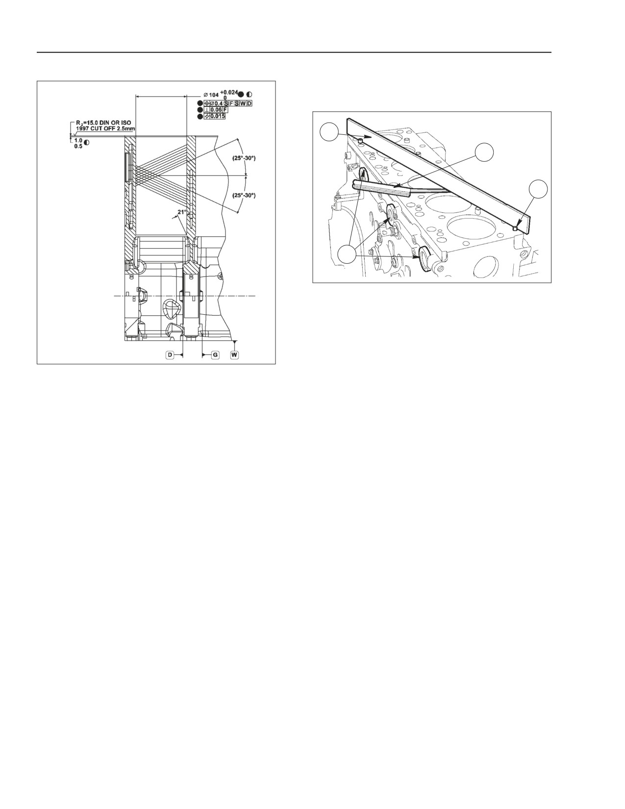
Verify that the crankcase cylinder head mating
surface does not show any warping. This check can
be accomplished by taking out dowels (4), with a
straight edge (2) and a thickness gauge (3). If there
are any deformed areas, resurface the block. The
warpage must not be greater than 0.075mm
BS06K269
Figure 2-142
(0.0030 in.).
CYLINDER BORE DIMENSIONS AND SPECIFICATIONS
IMPORTANT: When the repair work has been
IMPORTANT: In case of reconditioning all the bores
completed, check that the protrusion of the piston
must be machined to the standard increments of over
from the bore is not greater than the specified value.
sized bores 0.5mm (0.02in.).
After flattening, restore the bore countersink, as
Check the main bearing seats as follows:
shown on page 2-84.
• Install the bed caps on the supports without
bearing.
• Tighten the fastening bolts to the specified torque.
• Check with a internal comparator, that the seat
diameter is the same as the specified value.
If a value is found out of tolerance replace
crankcase.
2-84
Issued 11-06
Bur
87519804 NA
ENGINE REPAIR MANUAL
CHAPTER 2 - 667TA ENGINE OVERHAUL
CAMSHAFT TIMING
STEP 51
BS06K271
Figure 2-144
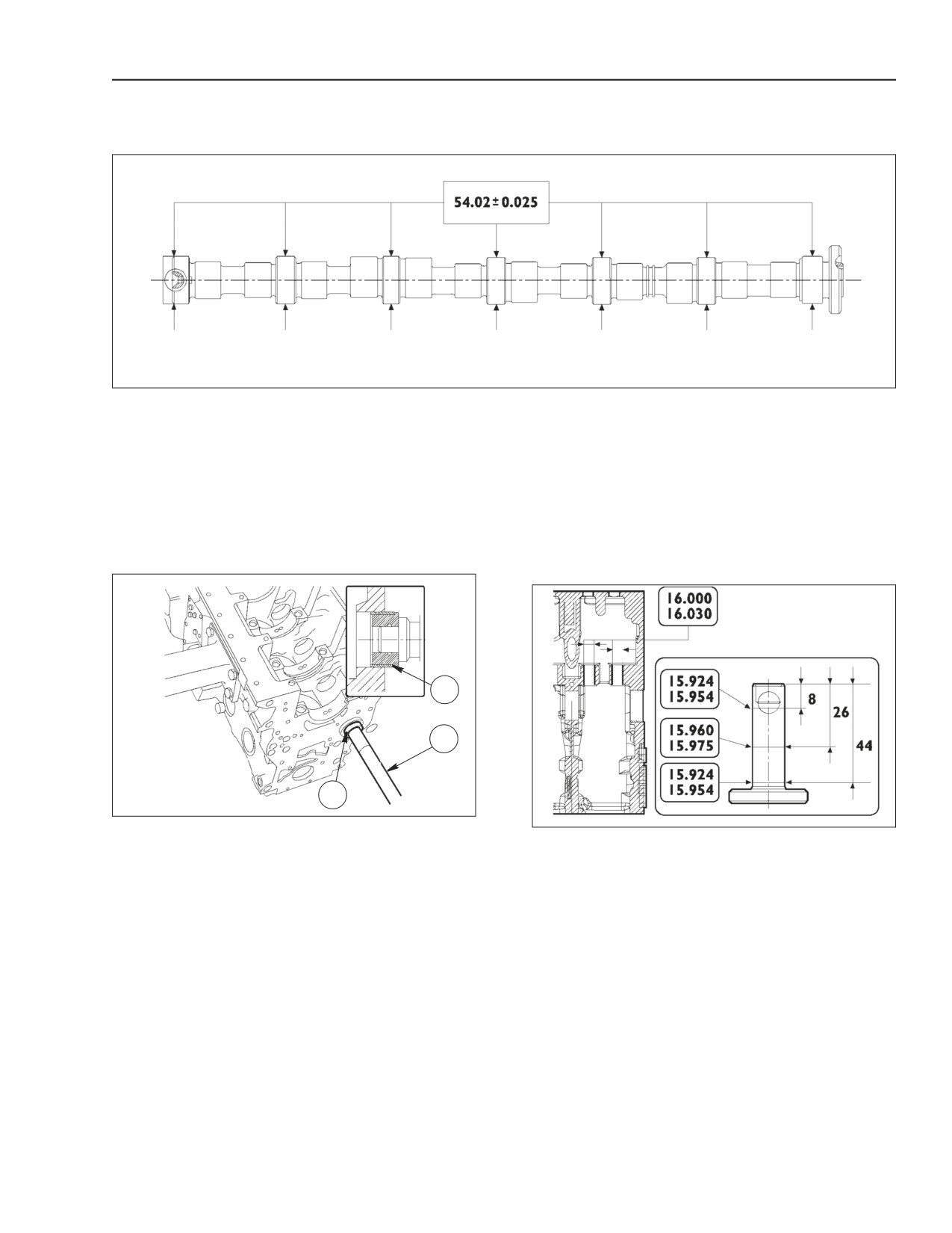
MAIN FEATURES OF CAMSHAFT
The shaft support journals and lobe surfaces must be
perfectly smooth. If they show signs of seizing and
scoring, replace the camshaft and respective
bearings.
REPLACING THE CAM BEARINGS
STEP 52
TAPPETS
1
2
1
BS06K272
Figure 2-145
BS06K273
Figure 2-146
When replacing the bearing (1) use a striker (2) and
MAIN FEATURES OF TAPPETS AND THEIR RESPECTIVE
a suitable driver to install.
SEATS ON THE CRANKCASE
IMPORTANT: When installing, the bearing (1) must
be aligned so that the lubrication holes are aligned
with the holes on the engine block seat.
87519804 NA
Issued 11-06
Bur
2-85
ENGINE REPAIR MANUAL
CHAPTER 2 - 667TA ENGINE OVERHAUL
INSTALLING THE TAPPETS AND CAMSHAFT
STEP 55
STEP 53
1
2
1
BS06K276
Figure 2-149
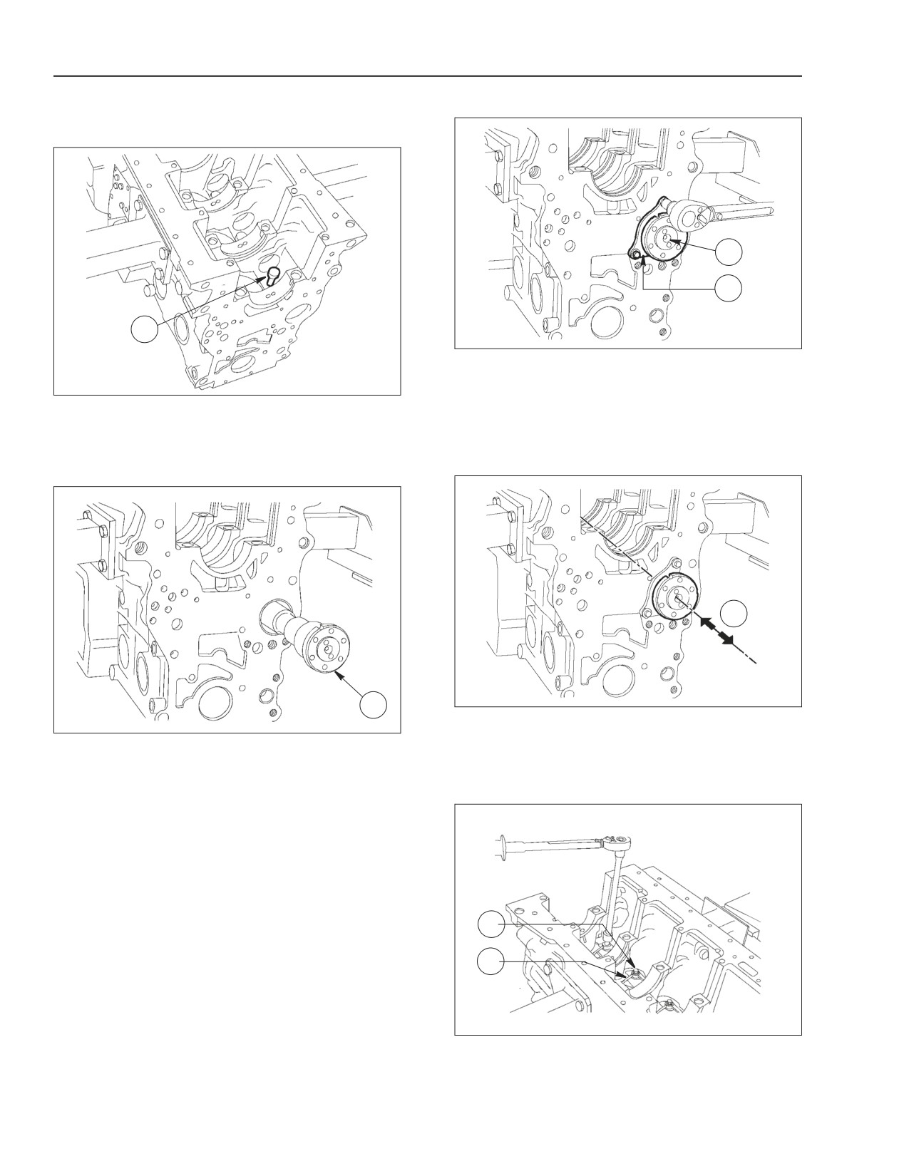
Place camshaft (1), retaining plate (2) with the slotted
hole facing the engine block upper side and the
BS06K274
Figure 2-147
stamping facing the operator, then tighten bolts to the
Lubricate tappets (1) and install them into their
specified torque 20 to 30 Nm (14.8 to 22.1 lb.-ft.).
respective seats of the engine block.
STEP 56
STEP 54
1
1
BS06K277
Figure 2-150
Check the camshaft end play (1). It must be between
BS06K275
Figure 2-148
0.13 - 0.23 mm (0.005 - 0.009 in.).
lubricate the camshaft support bearings and install
camshaft (1) taking care not to damage the bearings
STEP 57
or support seats.
1
2
BS06K278
Figure 2-151
Install nozzles (2) and tighten fastening bolts (1)
using general bolt torque specifications.
2-86
Issued 11-06
Bur
87519804 NA
ENGINE REPAIR MANUAL
CHAPTER 2 - 667TA ENGINE OVERHAUL
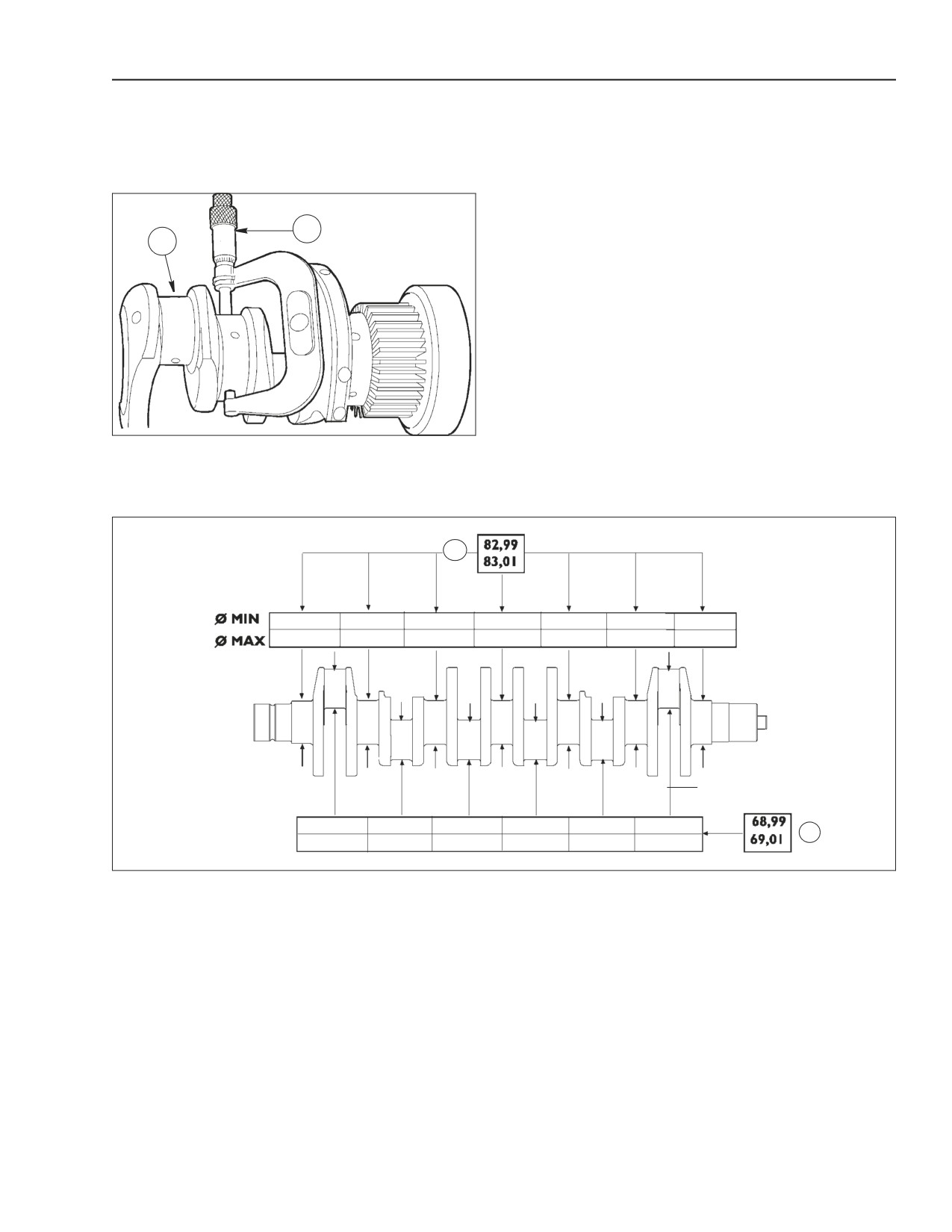
CRANKSHAFT
If any signs of seizing, scoring or out-of-roundness
are found on the journals and crankpins it is
MEASURING THE JOURNALS AND CRANKPINS
necessary to resurface the journals by machining.
Prior to resurfacing the journals (2), measure the
STEP 58
journals with a micrometer (1) to determine the
amount (diameter) by which the journals will have to
be reduced.
1
2
IMPORTANT: It is advisable to write down the
measured values on the table on page 2-86
figure 2-153
Reduction classes are 0.250 and 0.50 mm (0.0100
and 0.0200 in.).
IMPORTANT: Journals and crankpins must always
be ground to the same reduction class. The reduction
done on the journals and crankpins must be marked
with a special stamping on the side of the crank arm.
BS06K279
Figure 2-152
For reduced crankpins, use the letter M. For reduced
journals, use the letter B. For reduced crankpins and
journals, use the letters MB.
*
BS06K280
Figure 2-153
*DATA ON WHICH CRANKSHAFT JOURNALS AND CRANKPIN
MEASUREMENT VALUES ARE TO BE WRITTEN DOWN
87519804 NA
Issued 11-06
Bur
2-87
ENGINE REPAIR MANUAL
CHAPTER 2 - 667TA ENGINE OVERHAUL
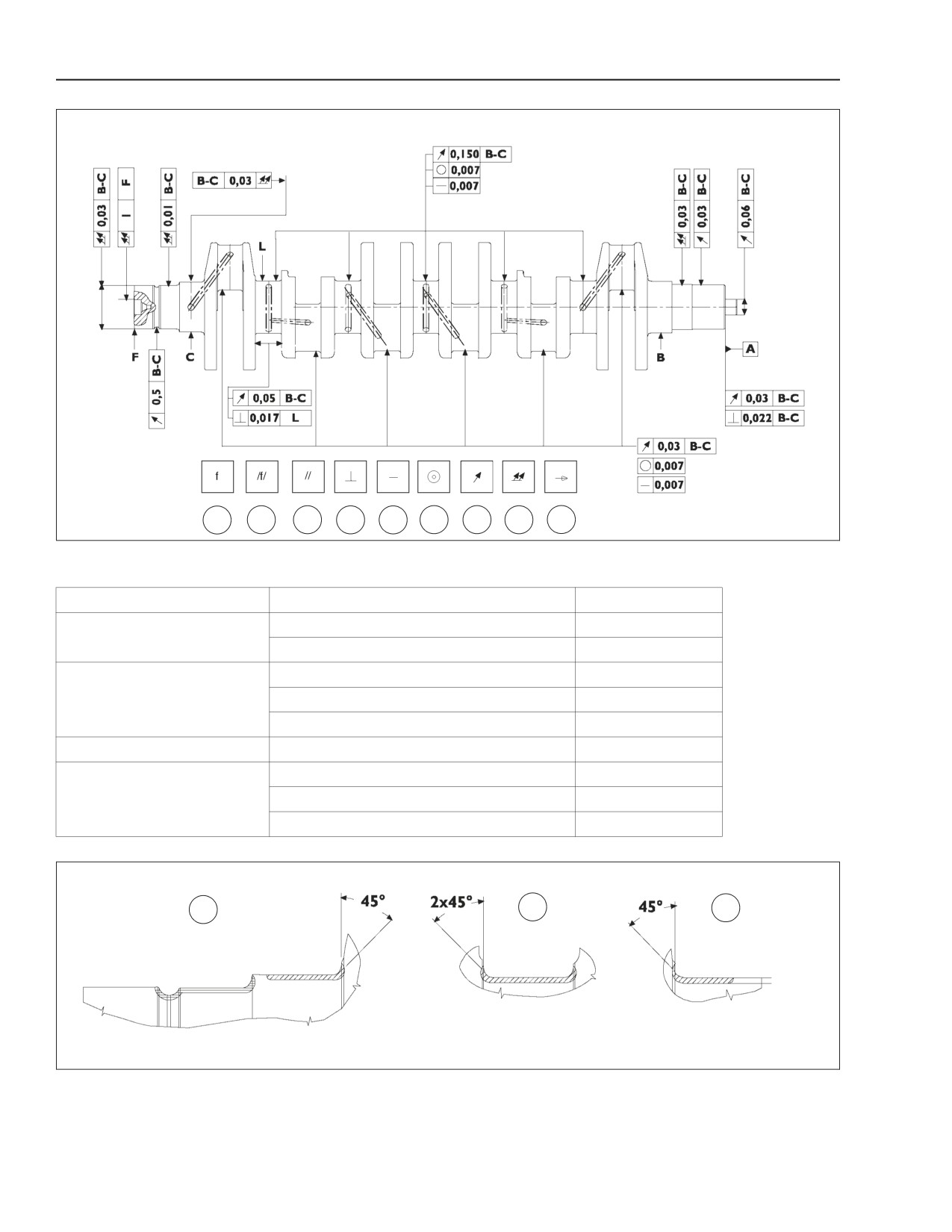
1
2
3
4
5
6
7
8
9
BS06K281
Figure 2-154
MAIN TOLERANCES OF THE CRANKSHAFT
TOLERANCES CONCERING
TOLERANCE-RELATED-FEATURE
GRAPHIC SYMBOL
Roundness
1
SHAPE
Cylindrical
2
Parallelism
3
ORIENTATION
Perpendicularity
4
Straightness
5
POSITION
Concentricity or Coaxially
6
Circular Oscillation
7
OSCILLATION
Total Oscillation
8
Taper
9
1
2
3
BS06K282
Figure 2-155
1. BEARINGS ON TIMING SIDE
2. BEARINGS ON TIMING SIDE
3. FIRST BEARING ON UPPER SIDE
2-88
Issued 11-06
Bur
87519804 NA
ENGINE REPAIR MANUAL
CHAPTER 2 - 667TA ENGINE OVERHAUL
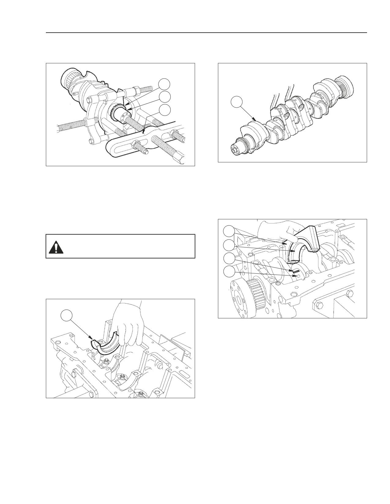
REPLACING THE OIL PUMP DRIVE GEARS
MEASURING THE JOURNAL ASSEMBLY PLAY
STEP 59
STEP 61
1
2
1
3
BS06K285
Figure 2-158
BS06K283
Figure 2-156
Install the crankshaft (1) in engine block.
Verify that the teeth of gear (1) are not damaged or
worn, otherwise proceed with removal by means of a
Check the play between the crankshaft journals and
suitable extractor (3) force-fitted on drive shaft (2).
their respective bearings by following the procedure
below.
When installing the new gear, the gear must be
heated for 10 minutes in a small furnace at a
STEP 62
temperature of 160° C ± 10% (320° F ± 10%) and
force onto the crankshaft.
1
WARNING: Always wear heat protective
2
gloves to prevent burning your hands.
3
SM121A
4
INSTALLING THE MAIN BEARINGS
STEP 60
1
BS06K286
Figure 2-159
Thoroughly clean the parts to eliminate any foreign
material and oil.
Place a piece of gauged wire (3) parallel to the axis
of the crankshaft pins (4).
Install caps (1), complete with half bearings (2), on
their respective supports.
BS06K284
Figure 2-157
IMPORTANT: If main bearings do not need
replacing, they must be installed in the same order
and position they had prior to being taken off.
IMPORTANT: Main bearings (1) are supplied as
spares, with incrementally reduced inner diameters
by 0.25 - 0.50 mm (0.0098 - 0.0197 in.).
Thoroughly clean the main half bearings (1) with
lubrication holes, then install them into their seats.
87519804 NA
Issued 11-06
Bur
2-89
ENGINE REPAIR MANUAL
CHAPTER 2 - 667TA ENGINE OVERHAUL
STEP 63
STEP 65
1
1
2
BS06K287
Figure 2-160
BS06K289
Figure 2-162
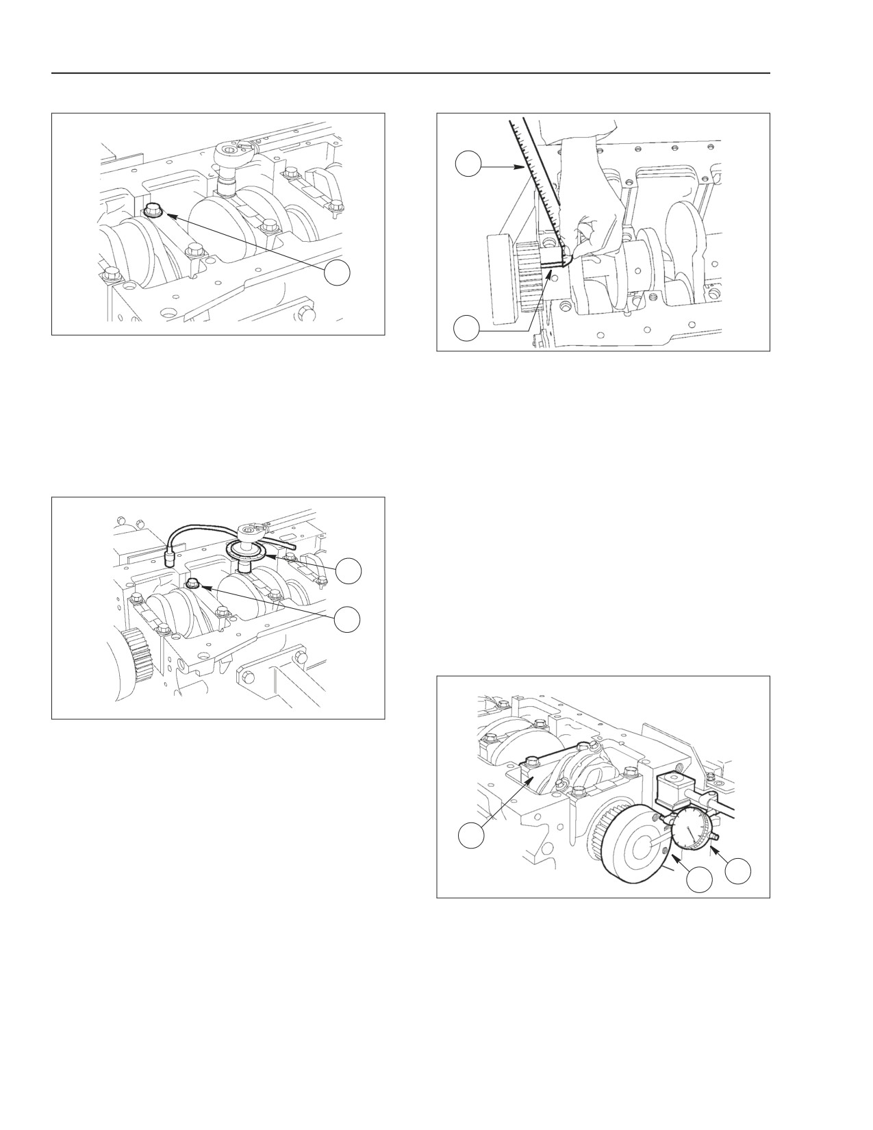
Fasten pre-lubricated bolts (1) by tightening them in
three phases.
Take the caps off the supports.
•
1st phase with a torque wrench at 44 - 56 Nm
The play between the main bearings and the pins
(32.5 - 41.3 lbf ft.).
can be found by comparing the width of the
•
2nd phase with a torque wrench at 74 -86 Nm
calibrated wire (2) at the narrowest point with the
(54.6 -63.4 lbf ft.).
scale on the envelope (1) containing the calibrated
wire.
STEP 64
The numbers on the scale indicate the backlash in
mm. (inches).
Replace the half bearings and repeat the check if a
different backlash value is found. Once the specified
backlash is obtained, lubricate the main bearings and
1
install the supports by tightening the fastening bolts
as previously described.
2
CHECKING CRANKSHAFT SHOULDER PLAY
STEP 66
BS06K288
Figure 2-161
•
3rd phase with a suitable tool (1) placed as shown,
tighten bolts (2) further to an angle of 90° ± 5°
1
2
3
BS06K290
Figure 2-163
The shoulder play is checked by placing a magnetic
comparator (2) on the drive shaft (3) as shown in the
figure: normal assembly play is 0.068 to 0.410 mm
(0.0027 to 0.0161 in.).
If play falls out of the window, replace the main thrust
half bearings of the second last rear support (1) and
repeat the clearance check between output shaft
pins and main half bearings.
2-90
Issued 11-06
Bur
87519804 NA
ENGINE REPAIR MANUAL
CHAPTER 2 - 667TA ENGINE OVERHAUL
CONNECTING ROD-PISTON ASSEMBLY
4
3
1
7
5
2
8
6
BS06K291
Figure 2-164
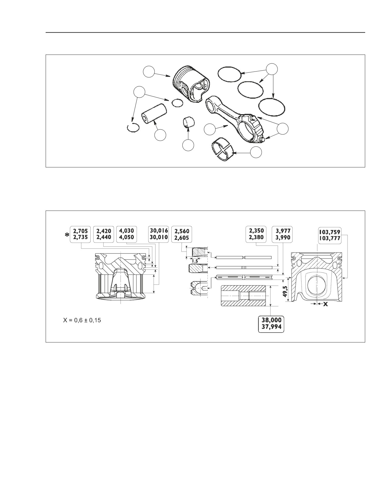
PARTS MAKING UP THE CONNECTING ROD - PISTON ASSEMBLY
1. RETAINING RINGS
3. PISTON
5. ROD CAP BOLTS
7. CONNECTING ROD
2. WRIST PIN
4. PISTON RINGS
6. HALF BEARINGS
8. BEARING
BS06K296
Figure 2-165
DATA ON PISTON, PINS AND SPRING RINGS
* DIMENSION IS TAKEN ON 101 MM DIAMETER
IMPORTANT: Pistons are supplied as spares
incriminated in sizes by 0.4mm (0.016 in.)
87519804 NA
Issued 11-06
Bur
2-91
ENGINE REPAIR MANUAL
CHAPTER 2 - 667TA ENGINE OVERHAUL
STEP 67
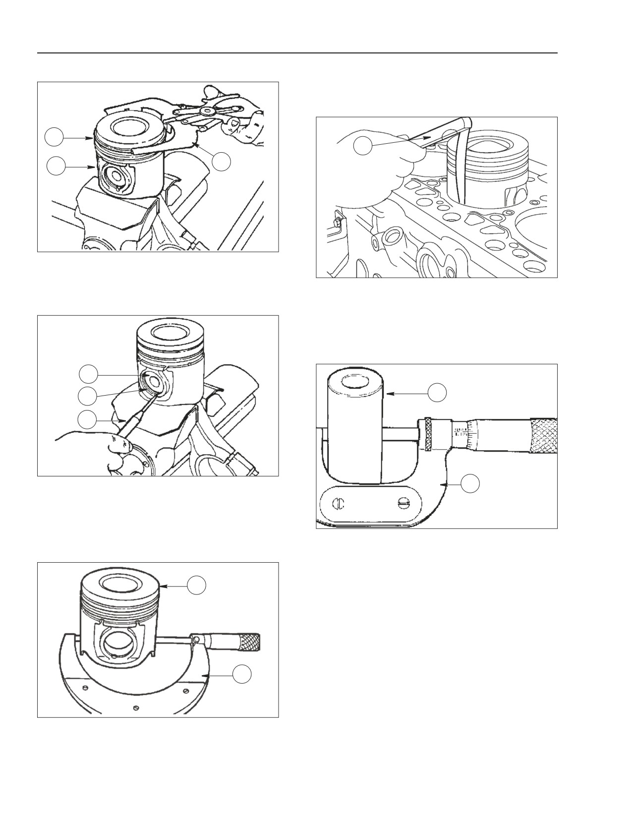
IMPORTANT: The diameter must be measured
49.5mm (1.95 in.) from the piston skirt base.
STEP 70
1
1
3
2
BS06K292
Figure 2-166
Taking piston rings (1) off piston (2) by means of
pliers (3).
BS06K295
Figure 2-169
The play between the piston and the cylinder bore
STEP 68
can be measured by means of a thickness gauge (1).
PISTON PINS
STEP 71
1
1
2
3
BS06K293
Figure 2-167
2
The piston rings (2) retaining the piston pin (1) are
removed by means of a scribe (3).
MEASURING THE PISTON DIAMETER
BS06K297
Figure 2-170
Measuring the piston pin diameter (1) by means of a
STEP 69
micrometer (2).
1
2
BS06K294
Figure 2-168
Measuring the piston diameter (1) by means of a
micrometer (2) to determine the assembly play.
2-92
Issued 11-06
Bur
87519804 NA
ENGINE REPAIR MANUAL
CHAPTER 2 - 667TA ENGINE OVERHAUL
CONDITIONS FOR CORRECT PIN/PISTON
STEP 74
MATCHING
2
STEP 72
1
1
3
BS06K300
Figure 2-173
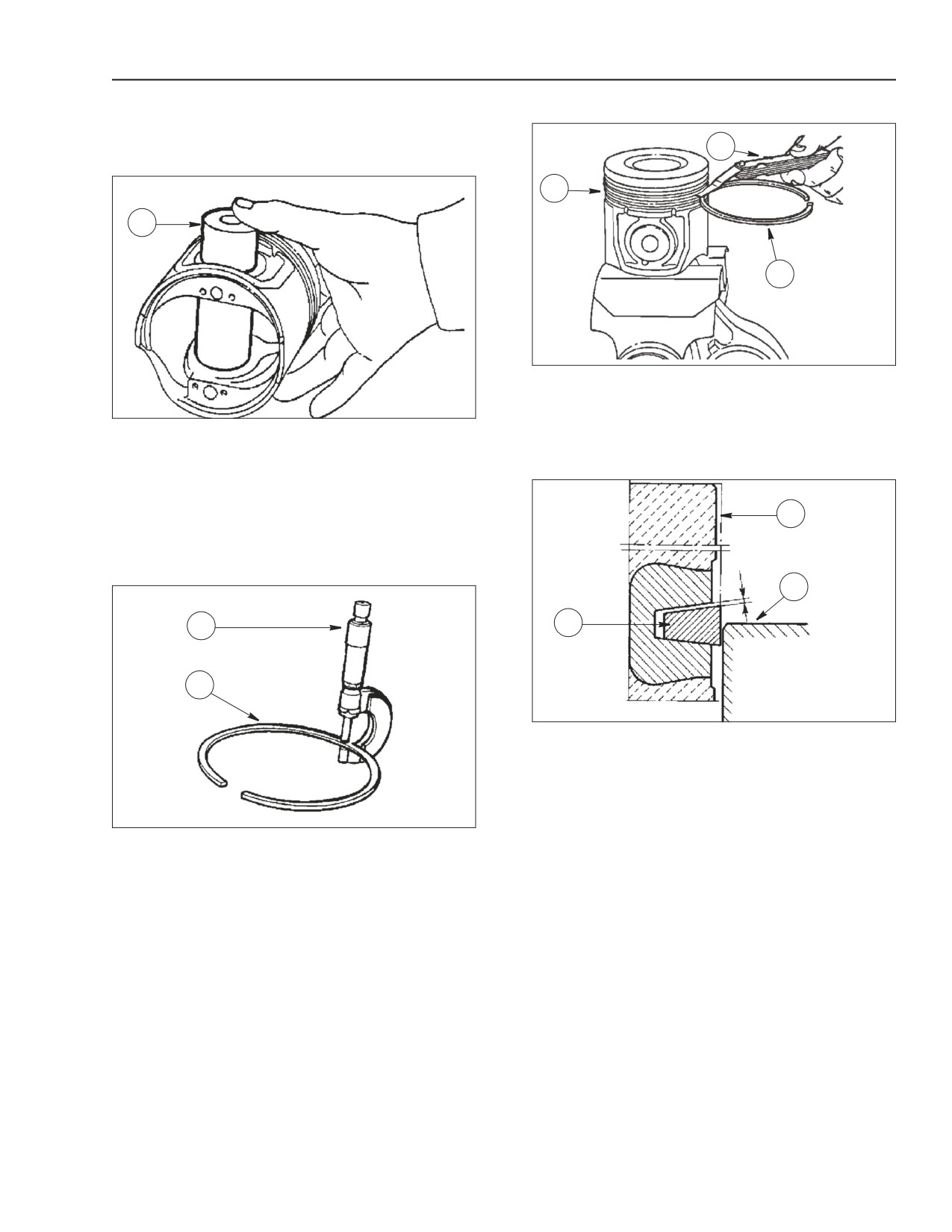
Use a thickness gauge (2) to check the play between
the seal rings (3) of the 2nd and 3rd slot and the
BS06K298
Figure 2-171
respective seats on piston (1).
Lubricate pin (1) and its respective seat on piston
hubs with engine oil. The pin must be inserted into
STEP 75
the piston by pressing with your fingers slightly and
must not slide out due to gravity.
2
PISTON RINGS
STEP 73
3
1
1
2
BS06K301
Figure 2-174
SCHEME FOR MEASURING PLAY X FOR THE TRAPEZOIDAL
RING
Due to the peculiar shape of the two trapezoidal
cross-sectioned seal ring, the play between the slot
and the ring itself must be measured as follows.
BS06K299
Figure 2-172
• Allow piston (1) to protrude from the engine block
Check the thickness of seal rings (2) by means of a
so that ring (2) protrudes out half way from the
micrometer (1).
cylinder bore (3).
• In this position, check by means of a thickness
gauge, the play (X) between the ring and the slot.
The value must correspond to the specified value.
87519804 NA
Issued 11-06
Bur
2-93
ENGINE REPAIR MANUAL
CHAPTER 2 - 667TA ENGINE OVERHAUL
STEP 76
1
2
3
BS06K302
Figure 2-175
Measure the piston ring gap (2) inserted into cylinder
bore (3) by means of a thickness gauge (1).
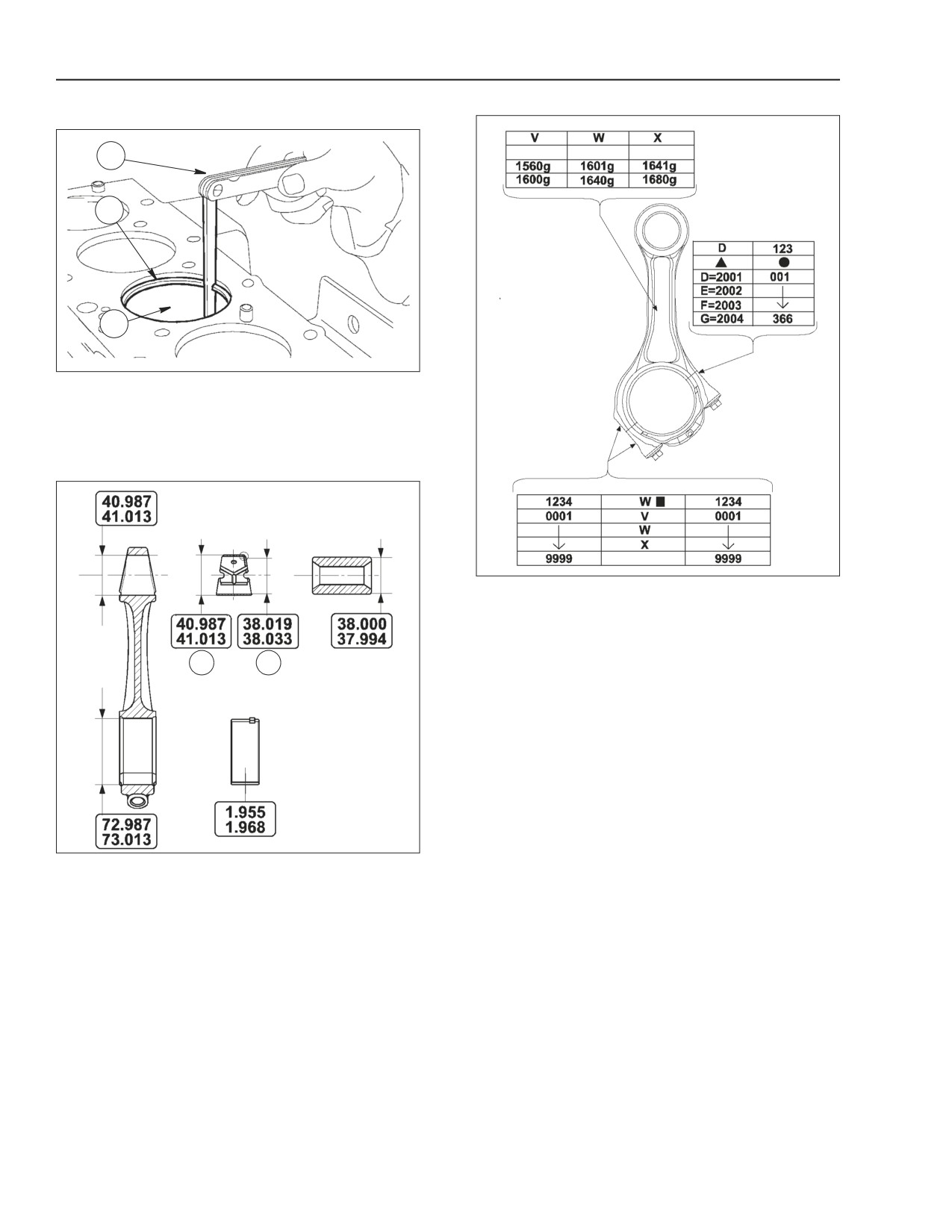
CONNECTING RODS
BS06K304
Figure 2-177
IMPORTANT: Each connecting rod is marked as
follows:
• By a number
(on the body and cap) which
**
indicates the connecting rod match and the
cylinder on which it is installed. In case of
replacement, it is necessary to number the new
connecting rod with the same number as the
replaced one.
• By letter
(on the connecting rod body) which
indicates the weight class of the factory-
assembled connecting rod.
V- 1560 to 1600 (marked in yellow)
W- 1601 to 1640 (marked in green)
BS06K303
Figure 2-176
X- 1641 to 1680 (marked in blue)
MAIN DATA OF CONNECTING ROD, PISTON PIN BEARING
Replacement rods are supplied class W and marked
AND HALF BEARINGS
in green.
* Value of inner diameter to be obtained after driving
Material removal is not permitted.
in connecting rod small-end and refacing by means
of a reamer.
** This dimension cannot be measured in released
condition.
IMPORTANT: The connecting rod-connecting rod
cap matching surfaces are knurled to ensure better
match.
Therefore, it is recommended not to remove knurls.
2-94
Issued 11-06
Bur
87519804 NA
ENGINE REPAIR MANUAL
CHAPTER 2 - 667TA ENGINE OVERHAUL
BEARINGS
CHECKING THE TWISTING
STEP 77
STEP 79
Verify that the bearings in the connecting rod small-
end is not loosened and does not show traces of
B
scoring or seizing. If it does replace them.
1
Removing and reassembling are carried out with the
same suitable driver.
2
A
When driving the bearings, make sure that the holes
allowing oil to flow onto the bearing and the
3
connecting rod small- end correspond to each other.
5
Use a reamer to reface the bearing to obtain the
required diameter.
4
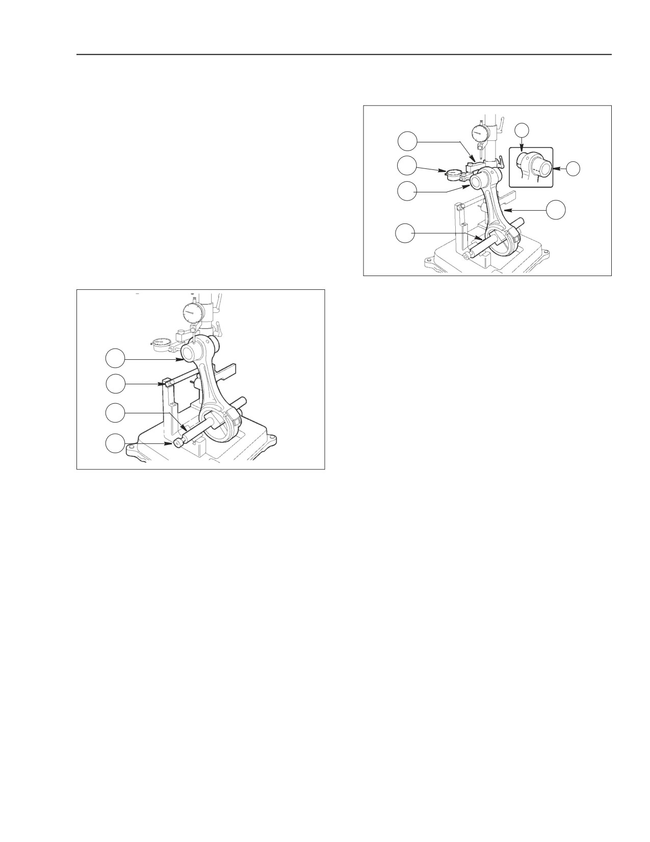
CHECKING THE CONNECTING RODS
STEP 78
BS06K306
Figure 2-179
Check connecting rod torsion (5) by comparing two
points (A and B) of pin (3) on the horizontal plane of
the connecting rod axis.
Place comparator (2) support (1) so that the
comparator is preloaded by approximately 0.5mm
1
(.02 in.) on pin (3) at point A, then set comparator (2)
to zero. Move spindle (4) with connecting rod (5),
2
then compare the deviation (if any) on opposite side
(B) of pin (3). The difference between A and B must
3
not be greater than 0.08mm (0.003 in.).
4
BS06K305
Figure 2-178
Check the centerlines of the connecting rods (1) are
parallel using proper device (5) as follows.
• Install connecting rod (1) on tool (5) spindle, then
secure it by means of bolt (4).
• Place spindle
(3) on V-blocks by putting
connecting rod (1) on stop bar (2).
87519804 NA
Issued 11-06
Bur
2-95
ENGINE REPAIR MANUAL
CHAPTER 2 - 667TA ENGINE OVERHAUL
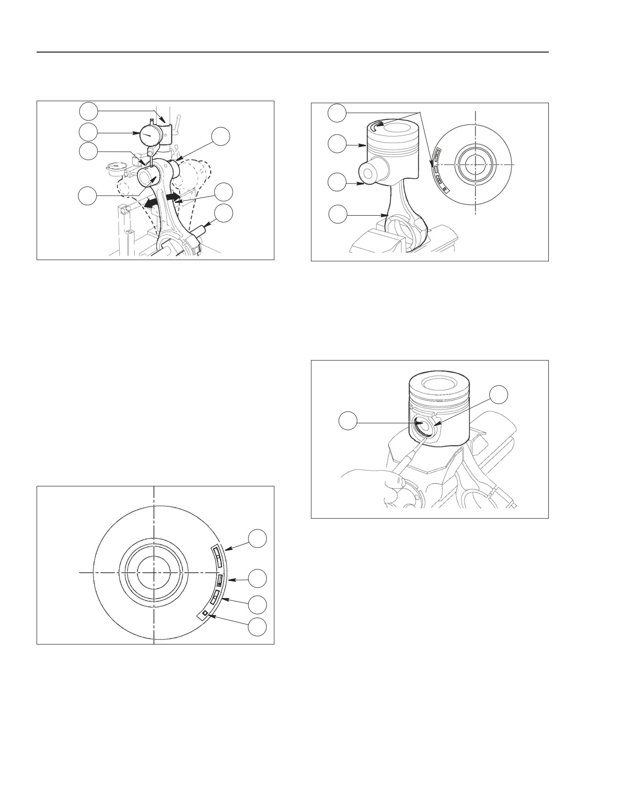
CHECKING THE FLEXING
4. Marking showing 1st slot insert testing.
STEP 80
STEP 81
1
1
2
D
2
C
3
5
3
4
4
BS06K307
BS06K309
Figure 2-180
Figure 2-182
Check connecting rod flexing (5) by comparing two
Connect piston (2) to connecting rod (4) by means of
points (C) and (D) of pin (3) on the vertical plane of
pin (3) so reference inscription (1) for installing piston
the connecting rod axis.
(2) in the cylinder bore and the numbers stamped on
connecting rod (4) can be seen as shown in the
Place comparator (2) vertical support (1) so that the
figure.
comparator rests on pin (3) at point (C).
Swing the connecting rod back and forth, looking for
STEP 82
the highest position of the pin. Under such condition,
set comparator (2) to zero.
Move the spindle with connecting rod (5) and repeat
2
the highest point check on opposite side (D) of pin
(3). The difference between points (C) and (D) must
not be greater than 0.08 mm (0.003 in.).
1
INSTALLING CONNECTING ROD-PISTON
ASSEMBLY CONNECTING ROD-PISTON
COUPLING
BS06K310
Figure 2-183
insert pin (1) fastening split rings (2)
1
2
3
4
BS06K308
Figure 2-181
The following reference data is engraved on the
piston crown.
1. Part number and design modification number
2. Arrow showing piston assembly direction into
cylinder bore, this arrow shall face the front key
of the engine block.
3. Manufacture date
2-96
Issued 11-06
Bur
87519804 NA
ENGINE REPAIR MANUAL
CHAPTER 2 - 667TA ENGINE OVERHAUL
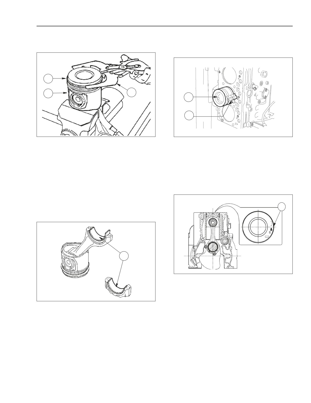
INSTALLING THE PISTON RINGS
INSTALLING THE CONNECTING ROD-PISTON
ASSEMBLIES IN THE CYLINDER BORES
STEP 83
STEP 85
1
2
3
1
2
BS06K311
Figure 2-184
BS06K313
Figure 2-186
Use pliers (3) to install piston rings (1) on piston (2).
Lubricate thoroughly the pistons, including the piston
The rings must be installed with the writing "TOP"
rings and the cylinder bore inside.
facing upwards and they should be inserted so that
Use band (2) to install the connecting rod-piston
the ring opens are turned so that they are offset to
assemblies (1) into the cylinder bores verify that:
each other by 120°.
• The number of each connecting rod corresponds
IMPORTANT: Spare piston rings are supplied in the
to the cap matching number.
following dimensions:
STEP 86
• Standard, marked with yellow paint.
• Oversized by
0.4mm (0.016 in.), marked with
yellow/green paint.
1
STEP 84
1
BS06K314
Figure 2-187
SCHEME FOR INSTALLING THE CONNECTING ROD-PISTON
ASSEMBLY INTO THE TUNNEL
• The piston ring apertures are offset to each other
by 120°.
BS06K312
Figure 2-185
• All the connecting rod-piston assemblies weigh
Install the half bearings (1) both on the connecting
the same.
rod and the cap.
• The writing stamped on the piston crown (1) faces
IMPORTANT: If connecting rod bearings do not
the engine block front side, the notch on the piston
need replacing, they must be installed in the same
skirt corresponds to the position of oil nozzles.
order and position they had prior to being taken off.
No matching operation must be carried out on half
bearings.
87519804 NA
Issued 11-06
Bur
2-97
ENGINE REPAIR MANUAL
CHAPTER 2 - 667TA ENGINE OVERHAUL
MEASURING CRANK PIN ASSEMBLY PLAY
STEP 89
STEP 87
1
2
BS06K317
Figure 2-190
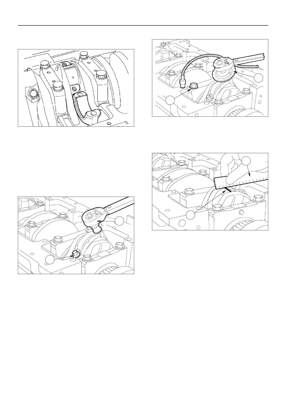
Apply a proper tool (1) on the compass wrench, then
BS06K315
Figure 2-188
tighten bolts (2) further in a crisscross sequence. See
The play can be measured by following the
torque specifications on page 2-14.
procedure below.
• Thoroughly clean the parts and eliminate any
STEP 90
traces of oil.
• Place a piece of gauged wire (2) on crankshaft
2
pins (1).
• Install the connecting rod caps
(3) with their
respective half bearings (4).
STEP 88
1
2
BS06K318
Figure 2-191
Take off the cap and calculate the existing play by
comparing the width of gauged wire (1) with the scale
graduation shown on the wire envelope (2).
1
BS06K316
Figure 2-189
Tighten bolts (1) previously lubricated with engine oil
to the specified torque by means of a torque wrench
(2).
2-98
Issued 11-06
Bur
87519804 NA
ENGINE REPAIR MANUAL
CHAPTER 2 - 667TA ENGINE OVERHAUL
STEP 91
CHECKING PISTON PROTRUSION
STEP 92
3
1
2
2
1
BS06K319
Figure 2-192
If the measured play is different from the specified,
BS06K320
Figure 2-193
replace half bearings and repeat the check. Once the
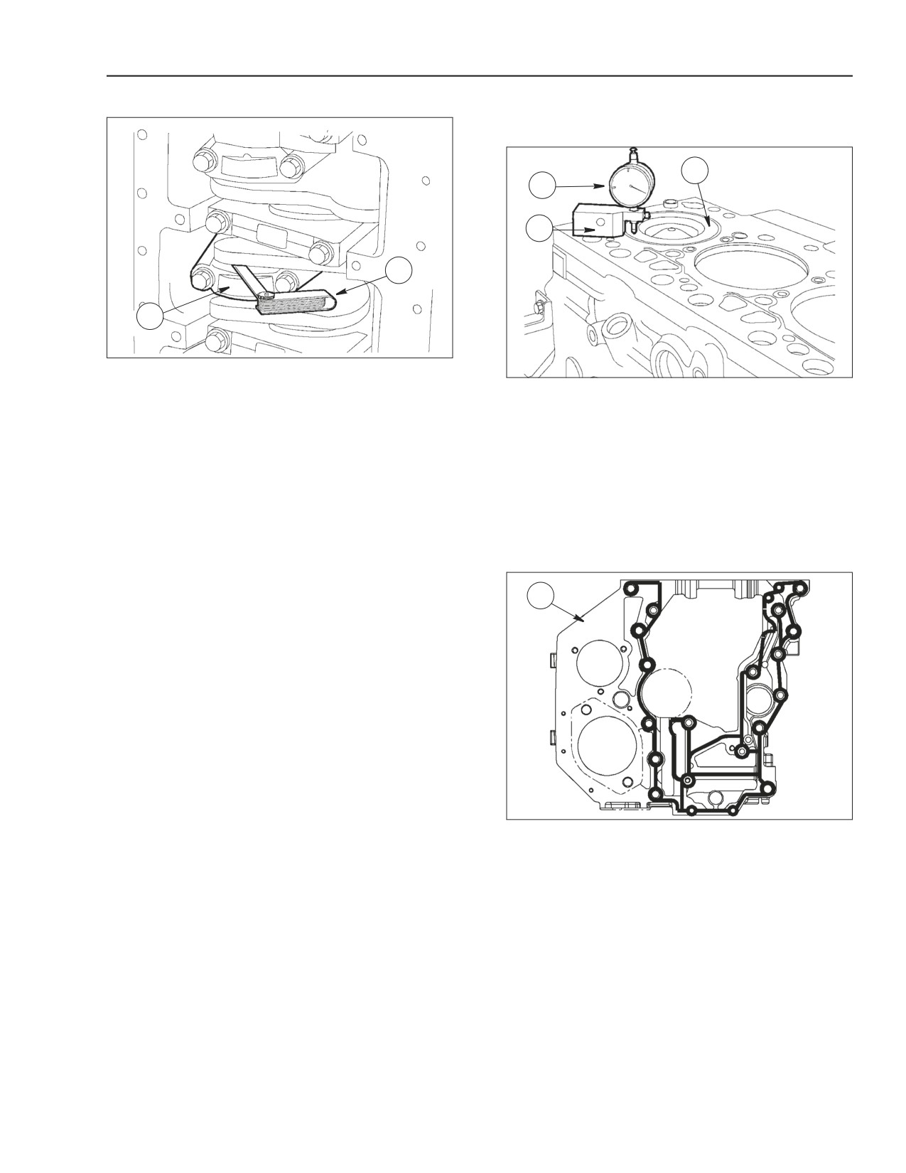
After the connecting rod-piston assemblies have
specified play has been obtained, lubricate the
been installed, check with a dial indicator (1)
connecting rod half bearings and install them by
equipped with base (2), the protrusion of pistons (3)
tightening the connecting rod cap fastening bolts to
at the top dead center relative to the engine block
specified torque see Torque Specs. on page 2-14.
upper plane. Protrusion shall be 0.28 - 0.52 mm
(0.011 - 0.0205 in.)
IMPORTANT: Prior to installing the connecting rod
cap fastening bolts verify that the diameter of the
TIMING GEAR CASE
diameter measured at the middle of the thread length
is not smaller than 0.1mm (0.004 in.) of the diameter
STEP 93
measured at about 10mm (0.39 in.) from the bolt
end.
1
Manually check that connecting rods (1) slide axially
on the crankshaft pins, and that the end play
measured by means of a thickness gauge (2) is 0.10
to 0.33mm (0.004 to 0.013 in.)
BS06K321
Figure 2-194
SEALANT APPLICATION AREA
Thoroughly clean timing gear box case (1) and the
engine block. To obtain a good seal the surface must
be clean. Apply a bead of LOCTITE 5205 to the case
a few millimeters in diameter. It should be uniform in
size without air bubbles, thin areas or voids. Any
imperfection should be corrected as soon as
possible. Avoid the use of excessive sealant to seal
the joint. Excessive sealant could come out from the
joint sides and cause lubrication passage clogging.
After applying the sealant, the joint should be
assembled within (10 - 20 minutes).
87519804 NA
Issued 11-06
Bur
2-99

ENGINE REPAIR MANUAL
CHAPTER 2 - 667TA ENGINE OVERHAUL
STEP 94
STEP 96
1
1
3
4
2
BS06K324
Figure 2-197
BS06K322
Figure 2-195
Turn crankshaft (4) and camshaft (1) so that when
installing the driven gear (2) on the camshaft the
DIAGRAM FOR TIGHTENING THE REAR TIMING GEAR CASE
FASTENING BOLTS
marks on the gears (2 and 3) are aligned.
Reconnect the case (1) to the engine block. Screw
STEP 97
the fastening bolts in the same position found at
removal and tighten them to the following torque
values in the sequence shown below.
Bolts M12
65 to 89 Nm (48 to 66 lbf. -ft.)
1
Bolts M8
20 to 28 Nm (15 to 21 lbf.- ft.)
Bolts M10
42 to 52 Nm (31 to 38 lbf.- ft.)
VALVE TIMING
2
STEP 95
3
1
BS06K325
Figure 2-198
Install fastening bolts (1) fastening gear (2) to
camshaft (3) and tighten using general bolt torque
2
specifications.
3
BS06K323
Figure 2-196
Mark with a felt tip pen the tooth (3) of the drive gear
(1) installed on the crankshaft (2), having the mark
(→) for timing on the side surface.
2-100
Issued 11-06
Bur
87519804 NA
ENGINE REPAIR MANUAL
CHAPTER 2 - 667TA ENGINE OVERHAUL
FLYWHEEL COVER CASE
STEP 99
STEP 98
16
8
6
15
14
7
5
17
13
18
12
19
1
20
11
Figure 2-199
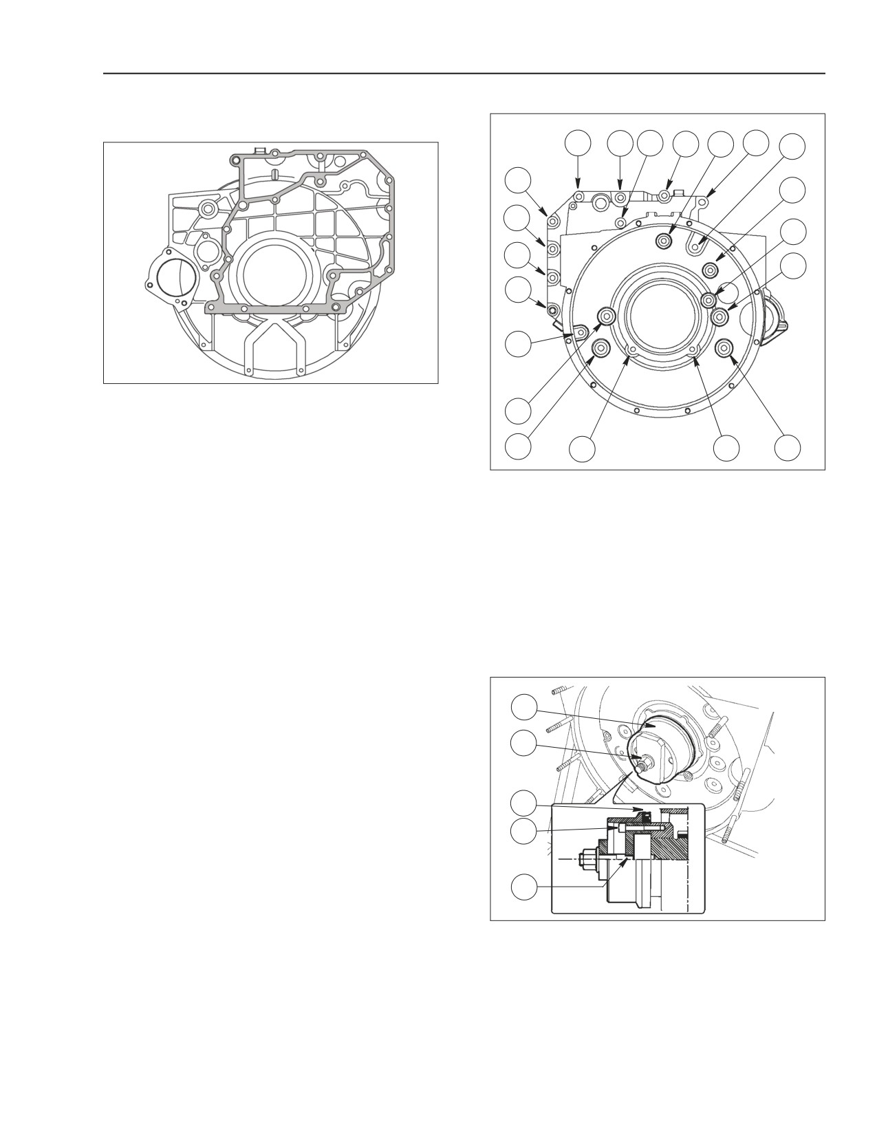
SEALANT APPLICATION AREA FOR FLYWHEEL COVER
2
CASE
Thoroughly clean the flywheel housing and timing
4
9
10
3
gear case mating surfaces. A good seal is only
obtained by a clean surface area to be sealed. Apply
BS06K327
Figure 2-200
a bead of LOCTITE 5205 to the case a few
TIGHTENING SEQUENCE FOR FLYWHEEL HOUSING
millimeters in diameter. It should be uniform in size
FASTENING BOLTS
without air bubbles, thin areas or voids. Any
Reconnect housing to engine block, screw the
imperfection should be corrected as soon as
fastening bolts back in the same position that they
possible. Avoid the use of excessive sealant to seal
were removed. tighten them to the following torque
the joint. Excessive sealant could come out from the
values in the sequence shown in the figure above.
joint sides and cause lubrication passage clogging.
Bolts M2
75 to 95 Nm (55 to 70 lbf ft.)
After applying the sealant, the joint should be
Bolts M10
32 to 53 Nm (32 to 39 lbf ft.)
assembled within (10 - 20 minutes).
STEP 100
1
2
3
4
5
BS06K328
Figure 2-201
Apply part (5) of Special Tool 380000664 on
crankshaft rear shank (6), secure it with bolts (4) and
force-fit the new seal ring (3).
Position part (1) on part (5), then screw nut (2) to fully
mount seal ring (3) in flywheel housing (7).
87519804 NA
Issued 11-06
Bur
2-101
ENGINE REPAIR MANUAL
CHAPTER 2 - 667TA ENGINE OVERHAUL
ENGINE FLYWHEEL
STEP 103
3
1
4
2
BS06K331
Figure 2-204
A
B
C
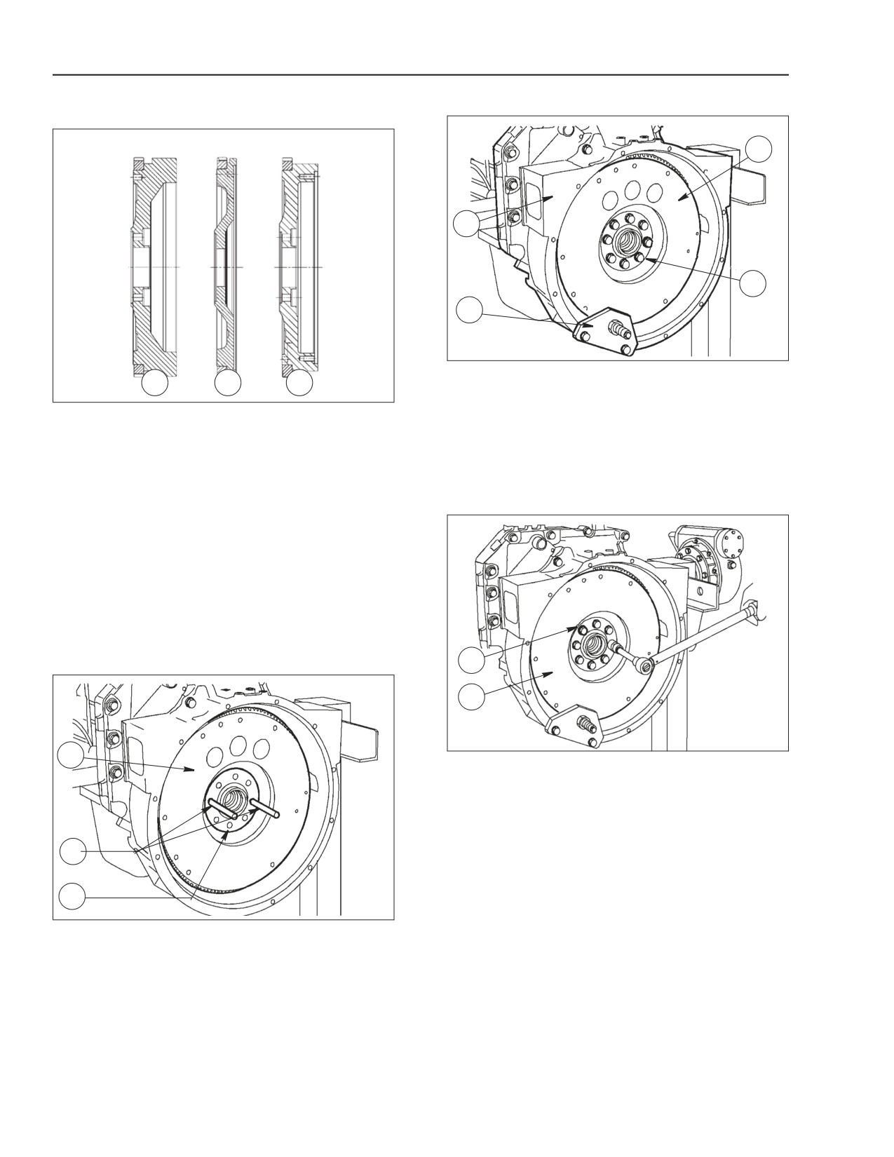
Apply tool (2), except for (667TA/EEG - 667TA/EEC
BS06K329
Figure 2-202
engines) to the flywheel case (1) to stop engine
A. ENGINES: 667TA/EEG - 667TA/EEC
flywheel (3) rotation.
B. ENGINES: 667TA/EBF - 667TA/EED -667TA/EDJ
Tighten bolts (4) fastening engine flywheel (3) to the
C. ENGINES: 667TA/EED - 667TA/EBD
crankshaft.
REPLACING ENGINE FLYWHEEL RING GEAR
STEP 104
STEP 101
Check the condition of ring gear teeth. If breaks or
excessive tooth wear is found, remove the ring gear
from the engine flywheel by using appropriate beater.
Then install the new gear ring after heating it to
150° C (302° F) for 15 to 20 minutes. Chamfering on
the ring gear must face the engine flywheel.
STEP 102
1
2
1
BS06K332
Figure 2-205
Tighten engine flywheel (2) fastening bolts (1) in two
separate phases.
•
1st phase- tighten to a torque of 26 to 34 Nm
(19 to 25 lbf ft.)
2
•
2nd phase- Tighten to 60° ± 5°
3
BS06K330
Figure 2-203
Screw two pins (2) of suitable length into the shaft
holes (3), then remove the engine flywheel (1) by
means of suitable harness and a hoist.
2-102
Issued 11-06
Bur
87519804 NA
ENGINE REPAIR MANUAL
CHAPTER 2 - 667TA ENGINE OVERHAUL
STEP 105
STEP 108
1
1
2
2
BS06K333
Figure 2-206
BS06K336
Figure 2-209
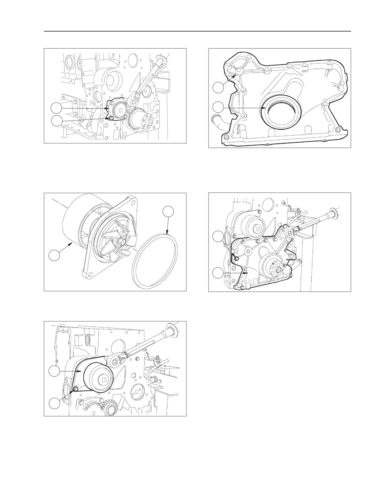
Install oil pump (1).
Take seal ring (2) off front cover (1), clean surfaces
Screw fastening bolts (2) and tighten them to the
thoroughly and apply Loctite 5205 sealant to the
specified torque 20 to 30 Nm (14.8 to 22.1 lb.-ft.).
surfaces.
STEP 106
STEP 109
2
1
1
2
BS06K334
Figure 2-207
BS06K337
Figure 2-210
Apply a new seal ring (2) to the water pump (1).
Thoroughly clean the surface of the front cover (2)
and attach it, with fastening bolts (1) and tighten
STEP 107
them to 20 to 30 Nm (14.8 to 22.1 lb.-ft.) specified
torque.
1
2
BS06K335
Figure 2-208
Install water pump (1).
Fasten bolts (2) and tighten them to 20 to 30 Nm
(14.8 to 22.1 lb.-ft.) specified torque.
87519804 NA
Issued 11-06
Bur
2-103
ENGINE REPAIR MANUAL
CHAPTER 2 - 667TA ENGINE OVERHAUL
STEP 110
STEP 112
1
7
2
1
2
3
4
6
5
BS06K340
Figure 2-213
BS06K338
Figure 2-211
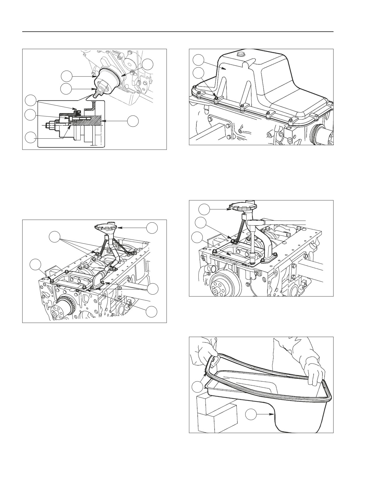
Install gasket on cast iron oil pan (sump) (1). And
Apply special tool (5) 380000666 on crankshaft front
tighten to the general bolt torque specifications in the
shank (6), secure it with bolts (4) and force-fit the
repair manual.
new seal ring (3). Position part (1) on part (5), then
screw nut (2) to fully mount seal ring (3) in the front
STEP 113
cover (7).
Only on engines 667TA/EEG- /EEC- /EBF- /EED
STEP 111
1
Only on engines 667TA/EED- /EBD- /EDJ
2
5
1
3
2
4
BS06K341
Figure 2-214
Install plate (3), the oil pick up tube (1) and tighten
3
the fastening bolts (2).
BS06K339
Figure 2-212
STEP 114
Install plate (3) and strainer (5), then screw down
fastening bolts (1-2-4) and tighten to the general bolt
torque specifications in the repair manual.
1
2
BS06K342
Figure 2-215
Set the gasket (1) on the steel oil pan (sump) (2).
2-104
Issued 11-06
Bur
87519804 NA
ENGINE REPAIR MANUAL
CHAPTER 2 - 667TA ENGINE OVERHAUL
STEP 115
STEP 117
1
1
2
2
3
3
BS06K343
Figure 2-216
BS06K345
Figure 2-218
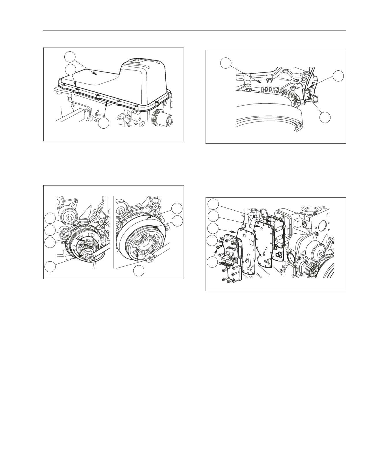
Install the oil pan (sump) (1) and apply the aluminium
Install a new seal ring on RPM sensor (3).
plate (3) to it. Tighten the bolts (2), to the general bolt
Install RPM sensor (3) on front cover (1) and tighten
torque specifications in the repair manual.
screw (2), to the general bolt torque specifications in
STEP 116
the repair manual.
STEP 118
1
5
2
1
6
3
2
4
3
5
4
7
BS06K344
Figure 2-217
Install the phonic wheel (1) and hub (2) on
BS06K346
Figure 2-219
crankshaft.
Install the following items on the engine block: a new
Tighten fastening bolts in two steps.
gasket (1), heat exchanger (2), a new gasket (3), and
•
1st step- tighten with a torque wrench to 45 to
oil filter bracket (4).
55Nm (33 to 40 lbf ft.)
Fasten bolts (5) and tighten to 20 to 30 Nm (14.8 to
•
2nd step- torque to 90° angle with degree wheel
22.1 lb.-ft.) the specified torque.
(4)
Install damper flywheel (5) and pulley (6).
Install fastening bolts (7) - torque to 61 to 75 Nm
(45 to 55 lbf ft.)
87519804 NA
Issued 11-06
Bur
2-105