New Holland 667TA/EEG, 667TA/EEC, 667TA/EBF, 667TA/EED, 667TA/EBJ, 667TA/EDJ. ENGINE REPAIR MANUAL (2006) - page 1
ENGINE REPAIR MANUAL
667TA/EEG
667TA/EEC
667TA/EBF
667TA/EED
667TA/EBJ
667TA/EDJ
ENGINE REPAIR MANUAL
Revision History
Issue
Issue Date
Applicable Machine
Remarks
667TA/EEG 667TA/EEC 667TA/EBF
First Edition
11-2006
87519804 NA
667TA/EED 667TA/EBJ 667TA/EDJ
ENGINE REPAIR MANUAL
ENGINE REPAIR MANUAL
TABLE OF CONTENTS
CHAPTER 1
DIAGNOSTICS
TABLE OF CONTENTS
1-1
CNH- EST DIAGNOSTIC TOOL
1-3
TROUBLESHOOTING
1-4
CHAPTER 2
667TA ENGINE OVERHAUL
TABLE OF CONTENTS
2-1
ENGINES
2-5
CODING OF SOURCE ENGINES
2-6
ENGINE PROPERTIES
2-6
GENERAL ENGINE FEATURES
2-7
CRANK GEAR COMPONENTS AND CYLINDER ASSEMBLY
2-9
VALVE GEAR - CYLINDER ASSEMBLY
2-12
TORQUE SPECIFICATIONS
2-14
SPECIAL TOOLS
2-16
667TA ENGINES
2-17
DESCRIPTION OF MAIN ENGINE COMPONENTS
2-18
EGR EXHAUST GAS RECIRCULATION SYSTEM
2-22
ENGINE LUBRICATION
2-30
ENGINE COOLING
2-35
HIGH PRESSURE ELECTRONIC INJECTION SYSTEM (COMMON RAIL)
. . 2-37
EDC7UC31 -ELECTRONIC CONTROL UNIT OPERATION
2-38
FUEL SUPPLY SYSTEM
2-40
COMMON RAIL
2-50
COMMON RAIL PRESSURE RELIEF VALVE
2-51
ELECTRO-INJECTOR
2-52
LOCATION OF THE MAIN ELECTRICAL COMPONENTS
2-55
CHECKING THE FUEL SYSTEM
2-67
ENGINE OVERHAUL ON THE BENCH
2-72
CHECKS AND SPECIFICATIONS ON ENGINE CRANKCASE
2-82
CRANKSHAFT
2-87
ENGINE FLYWHEEL
2-102
CYLINDER HEAD
2-107
VALVES
2-108
VALVE GUIDE
2-109
VALVE SEATS
2-110
VALVE SPRINGS
2-112
CYLINDER HEAD
2-112
RODS AND TAPPETS
2-115
CHAPTER 3
CHARGING AND START-UP
TABLE OF CONTENTS
3-1
STARTER MOTOR
3-3
ALTERNATOR
3-6
87519804 NA
Issued 11-06
Bur
I
ENGINE REPAIR MANUAL
CHAPTER 1
667TA
TIER III
DIAGNOSTICS
Issued 11-2006
Book/Form Number 87519804 NA
Copyright © 2006. .
Printed in U.S.A. • Bur
Source Code No. unknown
ENGINE REPAIR MANUAL
CHAPTER 1 - DIAGNOSTICS
CNH America LLC reserves the right to make improvements in design or changes in specifications at any time without incurring any
obligation to install them on units previously sold.
All data given in this publication is subject to production variations. Dimensions and weights are only approximate. Illustrations do
not necessarily show products in standard condition. For exact information about any particular product, please consult your Dealer
Revision History
Issue
Issue Date
Applicable Machines
Remarks
667TA/EEG 667TA/EEC 667TA/EBF
First Edition
11-2006
87519804 NA
667TA/EED 667TA/EBJ 667TA/EDJ
1-II
Issued 11-06
Bur
87519804 NA
ENGINE REPAIR MANUAL
CHAPTER 1
DIAGNOSTICS
TABLE OF CONTENTS
CNH- EST DIAGNOSTIC TOOL
1-3
TROUBLESHOOTING
1-4
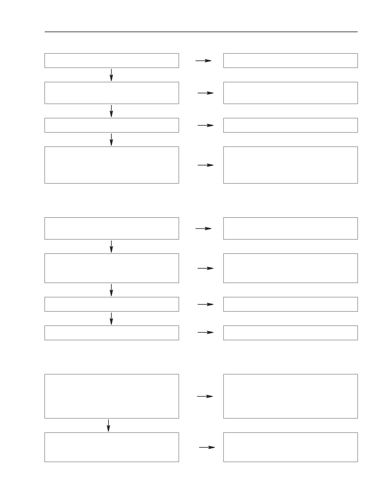
Engine Won’t Start
1-4
Engine Overheats
1-5
Engine Lacks Power And Runs Erratically
1-6
Engine Exhaust Smoke Black Or Dark Grey
1-7
Engine Exhaust Smoke Grey (Verging On White)
1-7
Engine Exhaust Smoke Light Blue
1-7
Engine Knocks Irregularly
1-8
Engine Stops
1-9
Excessive Or Insufficient Oil Pressure
1-9
Excessive Fuel Consumption
1-9
87519804 NA
Issued 11-06
Bur
1-1
ENGINE REPAIR MANUAL
CHAPTER 1 - DIAGNOSTICS
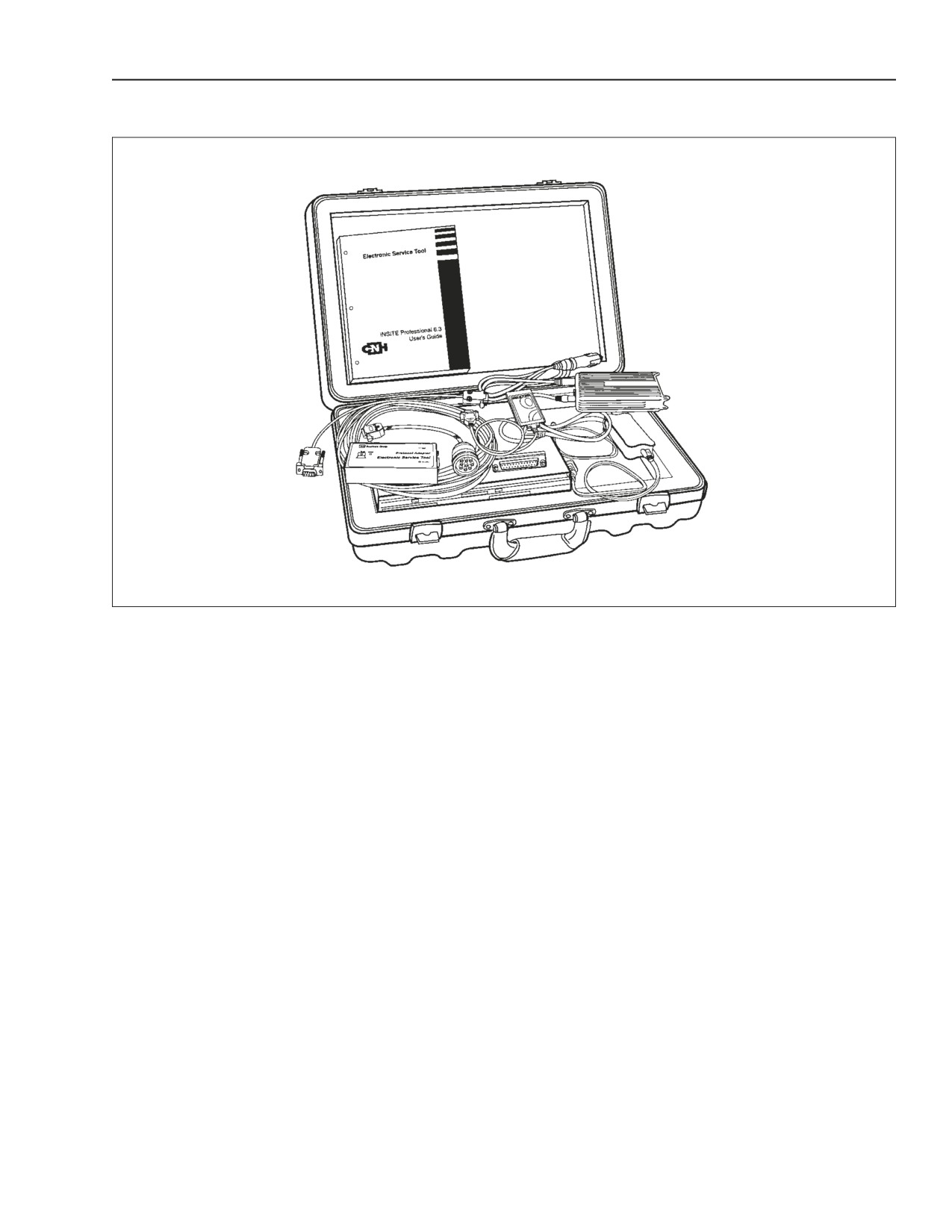
CNH- EST DIAGNOSTIC TOOL
BS06K009
Figure 1-1
The EST system allows diagnoses on machines by detecting the operating parameters of electronic control
components (control units, sensors etc.) and check flow rates, pressures and temperatures. It is also capable of
reading fault codes on the engine. To help with troubleshooting the engine failure mode.
87519804 NA
Issued 11-06
Bur
1-3
ENGINE REPAIR MANUAL
CHAPTER 1 - DIAGNOSTICS
TROUBLESHOOTING
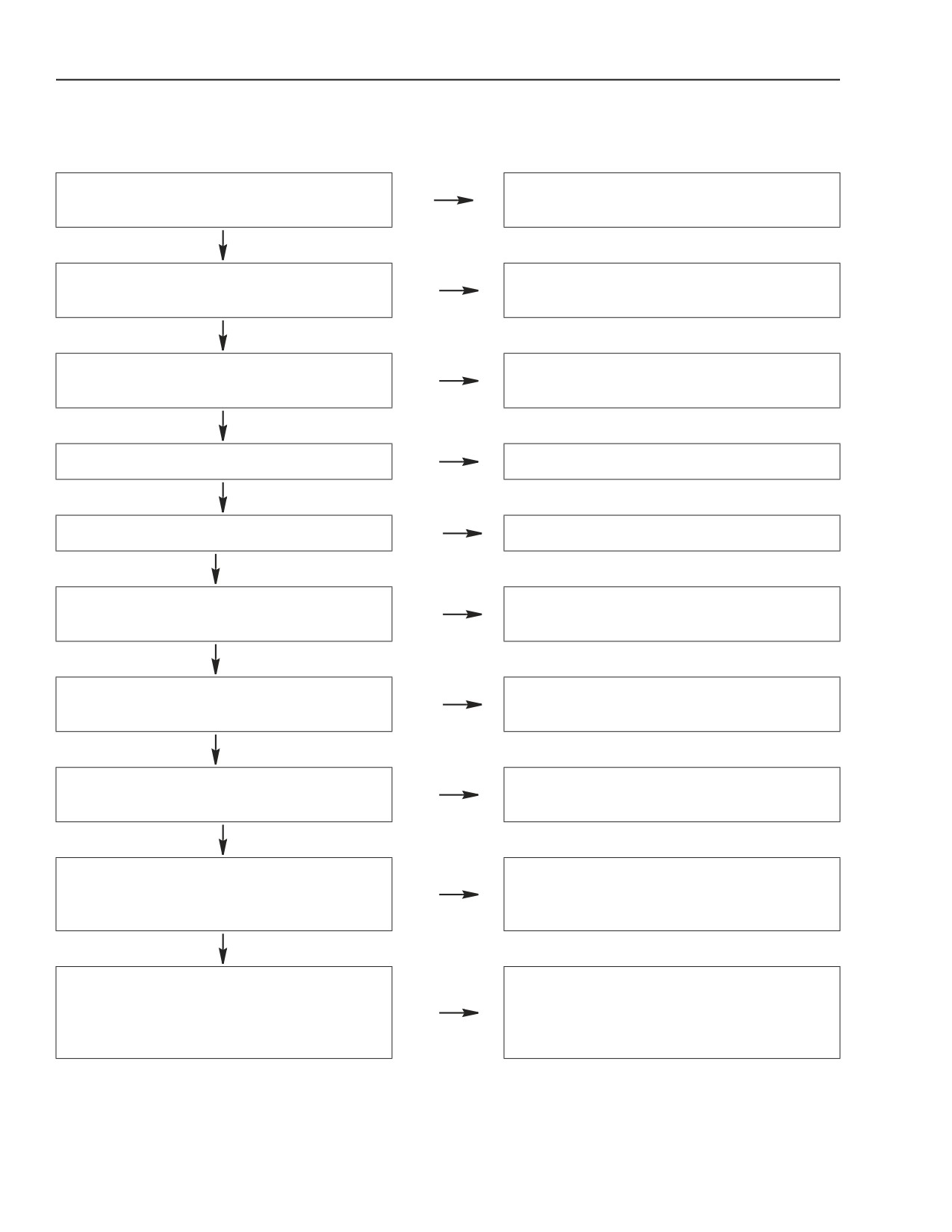
ENGINE WON’T START
Perform the checks described in the
Batteries fully charged.
No
Electrical section of the Shop manual.
Yes
Connections to battery terminals are tight
Inspect, clean, tighten or replace
No
and clean.
connections.
Yes
Perform the checks described in the
Starter motor working properly.
No
Electrical section of the Shop manual.
Yes
Pre-Post heating system working properly.
No
Check using a multi meter replace or repair.
Yes
Fuel filters plugged.
Yes
Replace.
No
The fuel system or injection pump shows
Yes
Check and repair air leaks.
signs of air in system.
No
Check and clean the fuel system including
The fuel system shows traces of water.
Yes
the fuel tank.
No
Check using Electronic Service Tool (EST)
High pressure pump working properly.
No
and repair or replace if necessary.
Yes
Check using Electronic Service Tool (EST).
Injectors working properly.
No
Check O-ring seal.
Replace injectors if defective.
Yes
Check each cylinder for proper
compression, overhaul the engine or make
Compression good on all cylinders.
No
repairs on defective parts (valves, piston
rings, etc.).
1-4
Issued 11-06
Bur
87519804 NA
ENGINE REPAIR MANUAL
CHAPTER 1 - DIAGNOSTICS
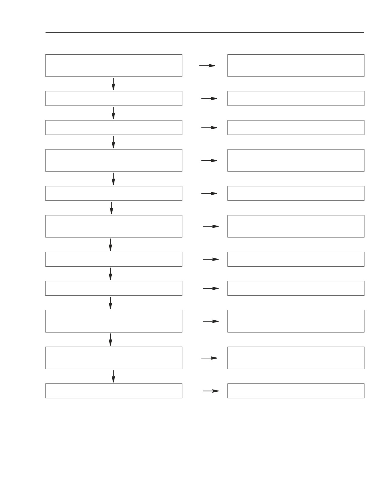
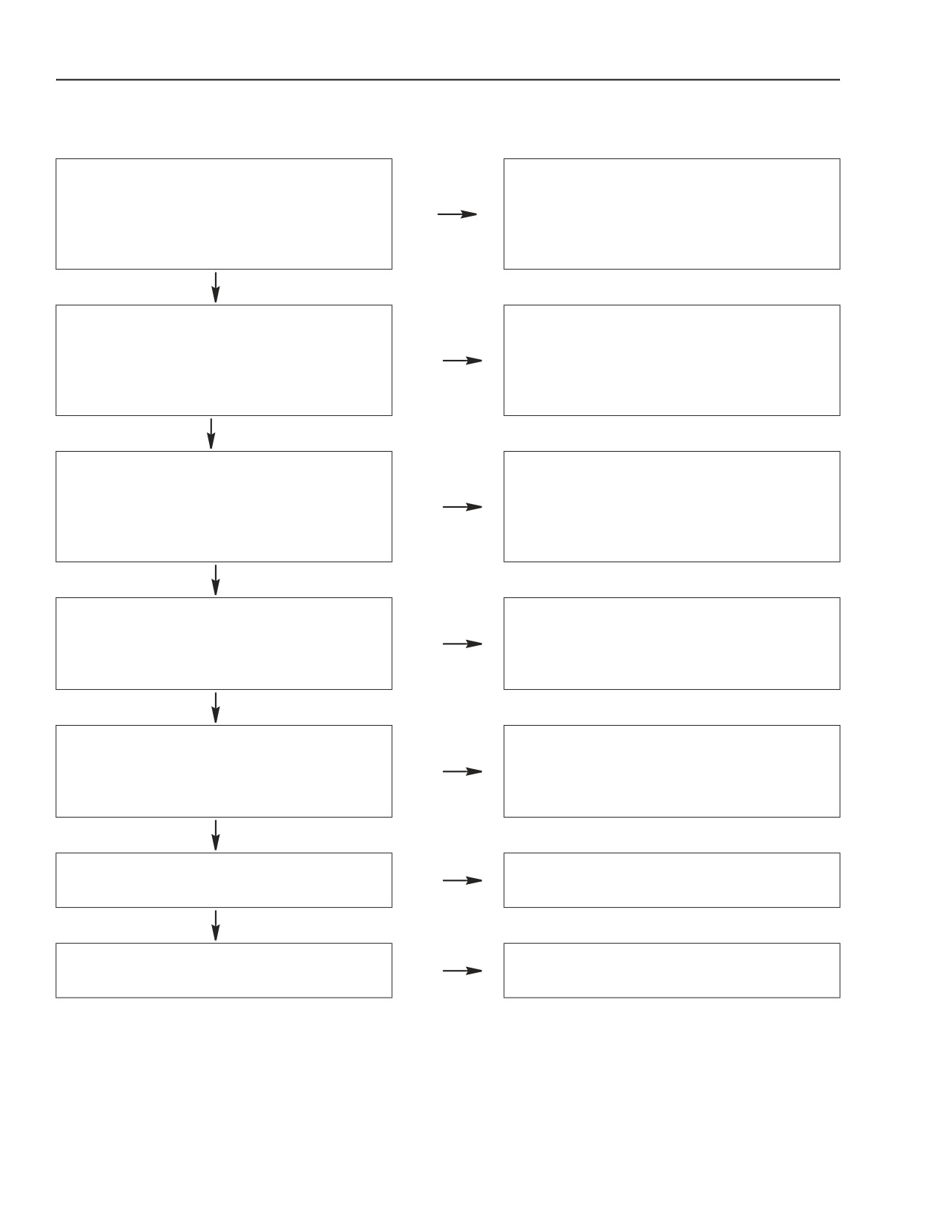
ENGINE OVERHEATS
Check for leaks, repair leaks and refill to
Coolant level correct.
No
proper level.
Yes
Fan working properly.
No
Replace.
Yes
Drive belts in serviceable.
No
Replace.
Yes
Check for leaks, bad bearing, overhaul or
Water Pump in working properly.
No
replace.
Yes
Thermostat working properly.
No
Replace.
Yes
Wash down, repair leaks and flush out
Radiator plugged or leaking.
Yes
radiator. If necessary replace radiator.
No
Oil in radiator fluid.
Yes
Replace oil cooler.
No
Air to Air Cooler and hoses leaking.
Yes
Clean or replace faulty parts.
No
Openings for coolant flow within the cylinder
Yes
Clean thoroughly.
head and engine block plugged.
No
Check and adjust for correct valve
Valve clearance correct.
No
clearance.
Yes
Cylinder head gasket in leaking.
Yes
Replace.
87519804 NA
Issued 11-06
Bur
1-5
ENGINE REPAIR MANUAL
CHAPTER 1 - DIAGNOSTICS
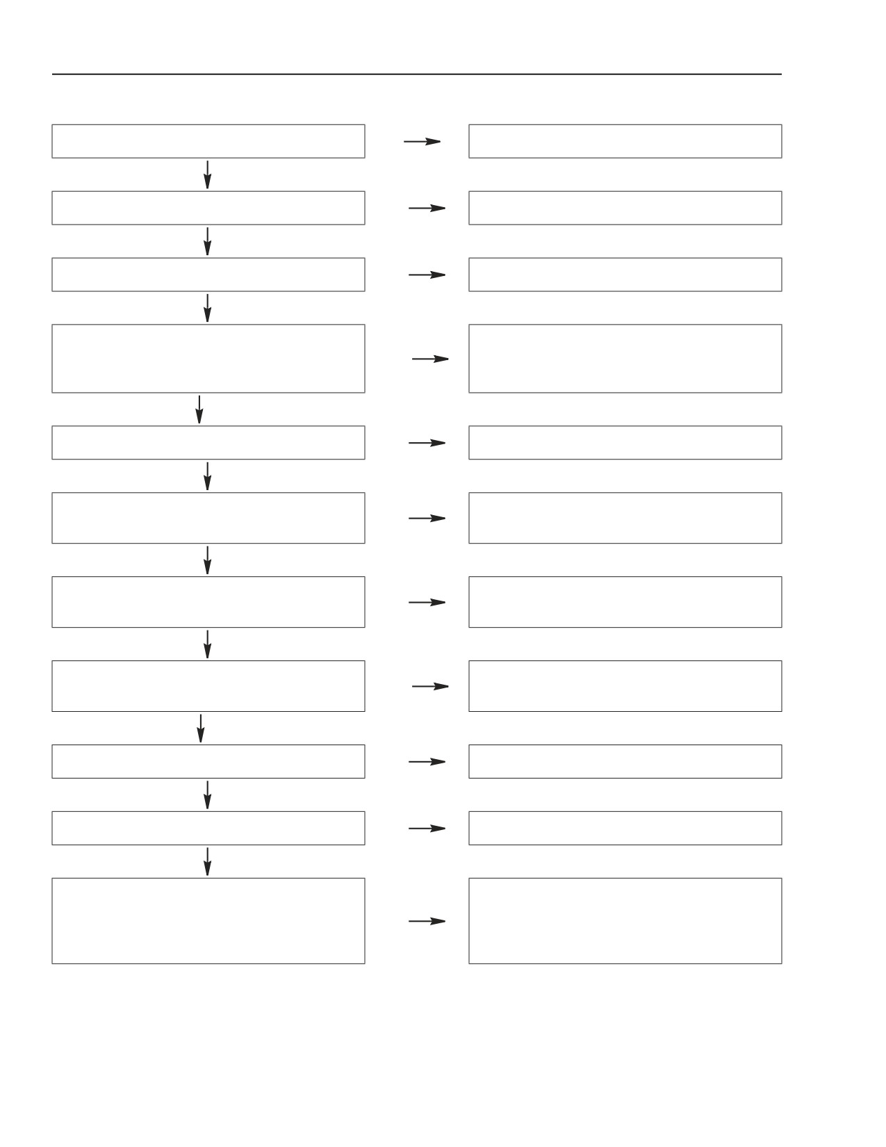
ENGINE LACKS POWER AND RUNS ERRATICALLY
Air filter plugged.
No
Clean the filter and replace if necessary.
Yes
Fuel filters in plugged.
No
Replace.
Yes
Fuel system working properly.
No
Check and make if necessary repair.
Yes
Take off the hoses and injection pump,
The fuel system shows impurities and or
Yes
clean and dry thoroughly, then if necessary
traces of water.
clean and dry the fuel tank.
No
Thermostat working properly.
No
Replace.
Yes
Check using the Electronic Service Tool
High pressure pump working properly.
No
(EST) and repair or replace if necessary.
Yes
Check using the Electronic Service Tool
Injectors working properly.
No
(EST) and repair or replace if necessary.
Yes
Check for leaks around O-rings and
High pressure fuel side leaking.
Yes
gaskets.
No
Turbocharger working properly.
No
Repair or replace the unit.
Yes
Correct valve clearance.
No
Adjust the clearance to proper value.
Yes
Check each cylinder for proper
compression, overhaul the engine or make
Compression good on all cylinders.
No
repairs on defective parts (valves, piston
rings, etc.).
1-6
Issued 11-06
Bur
87519804 NA
ENGINE REPAIR MANUAL
CHAPTER 1 - DIAGNOSTICS
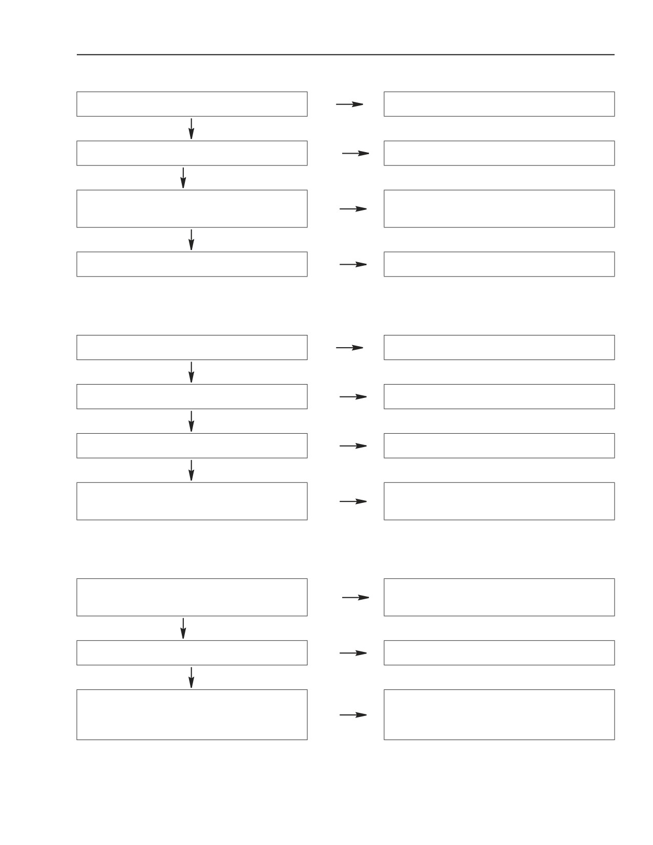
ENGINE EXHAUST SMOKE BLACK OR DARK GREY
Air filter plugged.
No
Clean the filter and replace if necessary.
Yes
Check using the Electronic Service Tool
Electronic fuel system working properly.
No
(EST) and repair or replace if necessary.
Yes
Fresh clean diesel fuel in tank.
No
Clean the tank and replace the fuel filter.
Yes
Check each cylinder for proper
compression, overhaul the engine or make
Compression good on all cylinders.
No
repairs on defective parts (valves, piston
rings, etc.).
ENGINE EXHAUST SMOKE GREY (VERGING ON WHITE)
Check using the Electronic Service Tool
Injectors working properly.
No
(EST) and repair or replace if necessary.
Yes
Possible flow of coolant into the combustion
Coolant level correct.
No
chamber; replace the cylinder head gasket
or overhaul the engine.
Yes
Pre-Post heating system working properly.
No
Check using a multi meter replace or repair.
Yes
Fresh clean diesel fuel in tank.
No
Clean the tank and replace the fuel filter.
ENGINE EXHAUST SMOKE LIGHT BLUE
Check: oil vapor breather, cylinder
compression. Leaks into or out of
Excessive oil consumption.
Yes
turbocharger. Leaks from valve guides.
Overhaul cylinder head or engine if
necessary.
No
Check the high pressure fuel pump O-ring,
Oil contaminated with diesel fuel.
Yes
injector O-ring for failure, or cylinder head
porosity.
87519804 NA
Issued 11-06
Bur
1-7
ENGINE REPAIR MANUAL
CHAPTER 1 - DIAGNOSTICS
ENGINE KNOCKS IRREGULARLY
Check the following items: Journal play and
out-of -roundness, bolt torque for main
Knock detected in the crankshaft.
Yes
journal caps and engine flywheel, oil
pressure. Replace the defective parts or
overhaul the engine.
No
Check the following items: Rod journal end
play and out-of -roundness, bolt torque for
Knock detected in the connecting rods.
Yes
connecting rod caps, connecting rod
torsion, straightness. Replace defective
parts or overhaul the engine.
No
Check the following items: Play between the
pistons and the cylinder liners, integrity of
Knock detected in pistons.
Yes
piston rings, play between the pins and the
piston hubs. Replace the defective parts or
overhaul the engine.
No
Check the following items: Play between the
rocker arms and the valves, injection pump
Knock detected in the cylinder head.
Yes
timing, valve timing. Adjust to proper
specification.
No
Check and replace if necessary the gears.
Inspect for broken springs, excessive play
Knock detected in valve gear.
Yes
between the stems and guides, and the
tappets and seats. Adjust the clearance.
No
Check using the Electronic Service Tool
Knock detected in injectors.
Yes
(EST) and repair or replace if necessary.
No
Replace loose screws and tighten all
Knock detected in the engine flywheel.
Yes
screws to the specified torque and angles.
1-8
Issued 11-06
Bur
87519804 NA
ENGINE REPAIR MANUAL
CHAPTER 1 - DIAGNOSTICS
ENGINE STOPS
Fuel tank filled.
No
Refuel and drain if necessary.
Yes
Fuel filters plugged.
Yes
Replace.
No
Check the circuit and make necessary
Fuel system in working properly.
No
adjustments or repairs.
Yes
Valve timing correct.
No
Make necessary adjustments.
EXCESSIVE OR INSUFFICIENT OIL PRESSURE
Oil pressure control valve working properly.
No
Check and replace if necessary.
Yes
Proper engine oil SAE viscosity.
No
Replace engine oil with proper viscosity oil.
Yes
Oil pump delivering proper pressure.
No
Check and replace if necessary.
Yes
Main bearings and connecting rod bearings
Replace the bearings and reface if
No
in acceptable condition.
necessary the crankshaft.
EXCESSIVE FUEL CONSUMPTION
Repair leaks (if any) and replace the worn
Fuel tank and lines leaking.
Yes
parts.
No
After cooler leaking.
No
Replace.
Yes
Check using the Electronic Service Tool
Electronic fuel injection system operating
No
(EST) and repair or replace if necessary.
properly.
87519804 NA
Issued 11-06
Bur
1-9
ENGINE REPAIR MANUAL
CHAPTER 2
667TA
TIER III
667TA ENGINE OVERHAUL
Issued 11-2006
Book/Form Number 87519804 NA
Copyright © 2006. .
Printed in U.S.A. • Bur
Source Code No. unknown
ENGINE REPAIR MANUAL
CHAPTER 2 - 667TA ENGINE OVERHAUL
CNH America LLC reserves the right to make improvements in design or changes in specifications at any time without incurring any
obligation to install them on units previously sold.
All data given in this publication is subject to production variations. Dimensions and weights are only approximate. Illustrations do
not necessarily show products in standard condition. For exact information about any particular product, please consult your Dealer
Revision History
Issue
Issue Date
Applicable Machines
Remarks
667TA/EEG 667TA/EEC 667TA/EBF
First Edition
11-2006
87519804 NA
667TA/EED 667TA/EBJ 667TA/EDJ
2-II
Issued 11-06
Bur
87519804 NA
ENGINE REPAIR MANUAL
CHAPTER 2 - 667TA ENGINE OVERHAUL
CHAPTER 2
667TA ENGINE OVERHAUL
TABLE OF CONTENTS
ENGINES
2-5
CODING OF SOURCE ENGINES
2-6
ENGINE PROPERTIES
2-6
GENERAL ENGINE FEATURES
2-7
CRANK GEAR COMPONENTS AND CYLINDER ASSEMBLY
2-9
VALVE GEAR - CYLINDER ASSEMBLY
2-12
TORQUE SPECIFICATIONS
2-14
SPECIAL TOOLS
2-16
667TA ENGINES
2-17
DESCRIPTION OF MAIN ENGINE COMPONENTS
2-18
Engine Block
2-18
Crankshaft
2-19
Crankshaft Oil Seals
2-19
Connecting Rods
2-20
Pistons
2-21
Camshaft
2-22
EGR EXHAUST GAS RECIRCULATION SYSTEM
2-22
Valve Control
2-23
Cylinder Head Engines: 667TA/EBF - 667TA/EBD - 667TA/EED
2-24
Cylinder Head Engines: 667TA/EEG - 667TA/EEC
2-25
Cylinder Head Engine: 667TA/EDJ
2-26
Valves and Valve Seats
2-27
Valve Bridges
2-27
Engine Head Machining
2-28
Engine Flywheel
2-28
Accessory Equipment Drive
2-29
ENGINE LUBRICATION
2-30
Oil Cooler
2-31
Oil Pressure Control Valve
2-31
By-pass Valve
2-31
Oil Pump
2-32
Oil Pan (Sump) Engines: 667TA/EEG-
667TA/EEC- 667TA/EBF- 667TA/EED- 667TA/EDJ
2-32
Oil Pan (Sump) Engines: 667TA/EED-
667TA/EBD
2-33
Engine Oil Vapor Recirculation
2-34
Blow-by Recirculation
2-34
ENGINE COOLING
2-35
Water Pump
2-36
HIGH PRESSURE ELECTRONIC INJECTION SYSTEM (COMMON RAIL)
2-37
EDC7UC31 -ELECTRONIC CONTROL UNIT OPERATION
2-38
Engine Preheating Element Control
2-38
Phase Recognition
2-38
Injection Control
2-38
Injection Pressure Closed Loop Control
2-38
Pilot and Main Injection Advance Control
2-38
87519804 NA
Issued 11-06
Bur
2-1
ENGINE REPAIR MANUAL
CHAPTER 2 - 667TA ENGINE OVERHAUL
Idle Speed Control
2-38
Overheating Protection
2-38
Maximum Engine Speed Limiting
2-38
Cut Off
2-38
Smoke Control Under Acceleration
2-38
After Engine Shut Down
2-38
Control Of Working Speed In Normal Operating Conditions
2-38
Recover Strategies
2-39
FUEL SUPPLY SYSTEM
2-40
Fuel Supply System Diagram
2-41
Fuel Filter
2-42
Mechanical Supply Pump- Normal Operating Condition
2-43
Mechanical Supply Pump- Outlet Overpressure Condition
2-43
Fuel System Bleeding
2-44
High Pressure Pump Type CP3.3
2-45
High Pressure Pump Inside Structure
2-47
Operating Principal
2-48
Theory Of Operation
2-49
COMMON RAIL
2-50
COMMON RAIL PRESSURE RELIEF VALVE
2-51
ELECTRO-INJECTOR
2-52
Injection End
2-52
Electro-injector
2-53
Pressure Limiter For Fuel Return
2-54
LOCATION OF THE MAIN ELECTRICAL COMPONENTS
2-55
EDC7UC31 Electronic Control Unit
2-56
Cabling Connector Pinout On Engine
2-57
Connector (A) Injectors Pinout Diagram
2-58
Connector (C) Sensors Pinout Diagram
2-58
Crankshaft Sensor
2-59
Camshaft Sensor
2-59
Boost Temperature - Pressure Sensor
2-60
Engine Oil Temperature - Pressure Sensor
2-60
Common Rail Fuel Pressure Sensor
2-61
Electro-injectors
2-62
Intake Air Pre-Post Resistance Heater and Relay
2-63
Coolant Temperature Sensor
2-64
Fuel Temperature Sensor
2-65
High Pressure Pump - Pressure Regulator
2-66
CHECKING THE FUEL SYSTEM
2-67
Low Pressure Supply Test
2-67
Low -pressure Pump
2-68
Test On the Pressure Relief Valve On the Common Rail
2-69
Test On Fuel Backflow From the Return
2-70
ENGINE OVERHAUL ON THE BENCH
2-72
Disassembling the Engine
2-72
CHECKS AND SPECIFICATIONS ON ENGINE CRANKCASE
2-82
Checks and Measurements
2-82
Checking the Eccentric Lift and Bearing Surface
2-83
Bearings
2-83
Checking the Crankcase Cylinder Head Mating Surface
2-84
Camshaft Timing
2-85
Replacing the Cam Bearings
2-85
Tappets
2-85
2-2
Issued
11-06
Bur
87519804 NA
ENGINE REPAIR MANUAL
CHAPTER 2 - 667TA ENGINE OVERHAUL
Installing the Tappets and Camshaft
2-86
CRANKSHAFT
2-87
Measuring the Journals and Crankpins
2-87
Replacing the Oil Pump Drive Gears
2-89
Installing the Main Bearings
2-89
Measuring the Journal Assembly Play
2-89
Checking Crankshaft Shoulder Play
2-90
Connecting Rod-Piston Assembly
2-91
Measuring The Piston Diameter
2-92
Piston Pins
2-92
Conditions For Correct Pin/Piston Matching
2-93
Piston Rings
2-93
Connecting Rods
2-94
Bearings
2-95
Checking the Connecting Rods
2-95
Checking the Twisting
2-95
Checking the Flexing
2-96
Installing Connecting Rod-Piston Assembly Connecting Rod-Piston Coupling
. 2-96
Installing the Piston Rings
2-97
Installing the Connecting Rod-Piston Assemblies In the Cylinder Bores
2-97
Measuring Crank Pin Assembly Play
2-98
Checking Piston Protrusion
2-99
Timing Gear Case
2-99
Valve Timing
2-100
Flywheel Cover Case
2-101
ENGINE FLYWHEEL
2-102
Replacing Engine Flywheel Ring Gear
2-102
CYLINDER HEAD
2-107
Removing the Valves
2-107
Checking Cylinder Head Water Seal
2-108
Checking the Cylinder Head Mating Surface
2-108
VALVES
2-108
Valve Cleaning, Check and Grinding
2-109
Checking Assembly Play, and Valve Centering
2-109
VALVE GUIDE
2-109
VALVE SEATS
2-110
Valve Seat Reconditioning-replacement
2-110
VALVE SPRINGS
2-112
CYLINDER HEAD
2-112
Installing the Cylinder Head
2-113
Installing Injectors
2-113
RODS AND TAPPETS
2-115
Rocker Arm Assembly
2-115
Locating Top Dead Center (TDC)
2-116
Valve Clearance Adjustment
2-116
Wiring Harness Connections To Engine
2-121
87519804 NA
Issued 11-06
Bur
2-3
ENGINE REPAIR MANUAL
CHAPTER 2 - 667TA ENGINE OVERHAUL
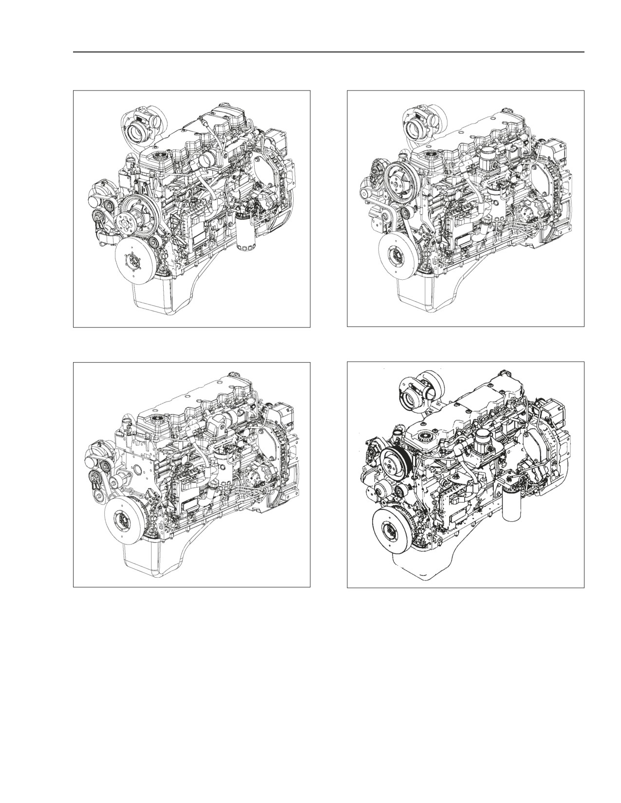
ENGINES
BS06K010
Figure 2-1
BS06K011
Figure 2-3
ENGINES: 667TA/EEG - 667TA/EEC
ENGINES 667TA/EED - 667TAEBF
BS06K012
Figure 2-2
BS06K628
Figure 2-4
ENGINES 667TA/EED - 667TAEBD
ENGINE 667TA/EDJ
87519804 NA
Issued 11-06
Bur
2-5
ENGINE REPAIR MANUAL
CHAPTER 2 - 667TA ENGINE OVERHAUL
CODING OF SOURCE ENGINES
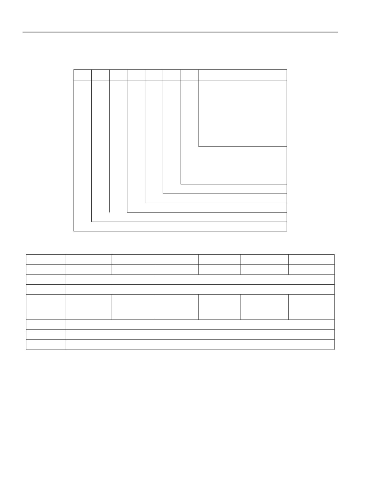
ENGINE MODEL BREAKDOWN DISCRIPTION
6
6
7
T
A
E
D
J
Engine Calibration (Power)
(D) J= 97 kW
(130 H.P.)
(E) G= 137 kW
(183.7 H.P.)
(E) D= 145 kW
(194.4 H.P.)
(E) C= 148 kW
(198.5 H.P.)
(B) F= 157 kW
(210.5 H.P.)
(B) D= 169kW
(226.6 H.P.)
Compression Ratio
B = 16.5:1 > 130 kW (174 H.P.)
D = 17.5:1
< 130 kW (174 H.P.)
E = 17.5:1 > 130kW (174 H.P.)
E= Electronic Injection (Common Rail)
A= Intercooled
T= Turbocharged
67= Total Displacement in Liters/ Cubic Inches- 6.7 Liters (409 Cubic Inches)
6= Number of Cylinders
ENGINE PROPERTIES
A
667TA
667TA
667TA
667TA
667TA
667TA
B
EEG
EEC
EBF
EED
EBD
EDJ
C
6 CYLINDERS
D
6728 cm³
(410.6 c.i.)
137 kW
148 kW
157kW
145kW
169 kW
97 kW
E
(183.7 h.p.)
(198.5 h.p.)
(210.5 h.p.)
(194.4 h.p.)
(226.6 h.p.)
(130.1 h.p.)
2100 rpm
2100 rpm
2000 rpm
2000 rpm
2000 rpm
2200 rpm
F
Electronic Direct Injection
G
Common Rail
H
T.A.A.
(Turbo Charged, Air to Air Cooling)
A. Type of engine
B. Engine model
C. Number of cylinders
D. Total displacement
E. Maximum power currently available
F. Type of Injection
G. Injection system
H. Air supply system
2-6
Issued 11-06
Bur
87519804 NA
ENGINE REPAIR MANUAL
CHAPTER 2 - 667TA ENGINE OVERHAUL
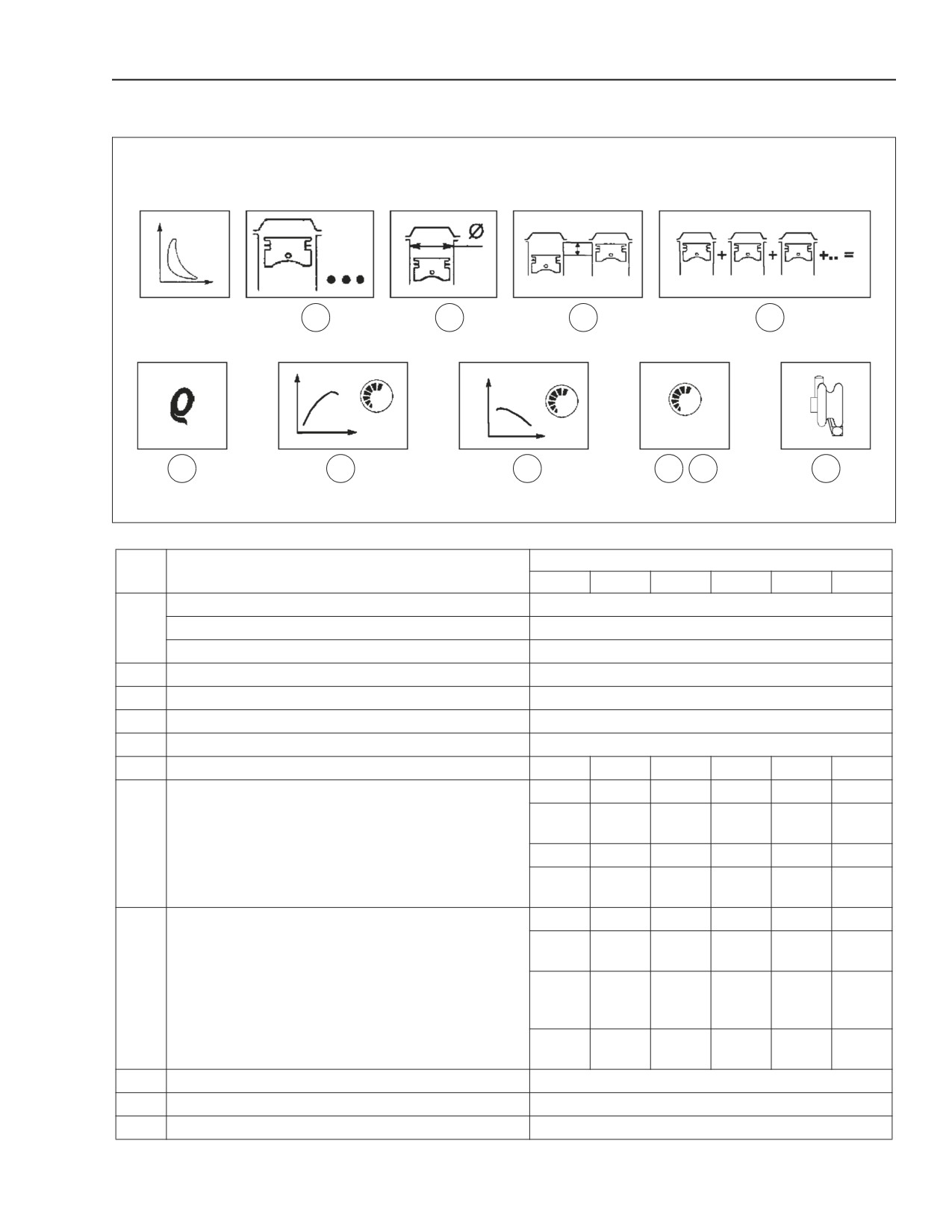
GENERAL ENGINE FEATURES
1
2
3
4
5
6
7
8
9
10
11
BS06K013
Figure 2-5
REF.
667TA
ENGINE TYPE
NO.
EEG
EEC
EBF
EED
EBD
EDJ
Cycle
4- Stroke diesel engine
1
Air
T.A.A. (Turbo charged, Air to Air cooling)
Injection
Direct
2
Number of cylinders
6 in-line
3
Bore
104 mm (4.1 inches)
4
Stroke
132 mm (5.2 inches)
5
Total displacement
6728cm³ (410.6 cubic inches)
6
Compression ratio
137 kW
148 kW
157 kW
145 kW
169 kW
97 kW
2100
2100
2000
2000
2000
2200
rpm
rpm
rpm
rpm
rpm
rpm
7
Maximum power rating (net power at flywheel ISO 14396)
184 hp
198 hp
211 hp
194 hp
227 hp
130 hp
2100
2100
2000
2000
2000
2200
rpm
rpm
rpm
rpm
rpm
rpm
710 Nm
810 Nm
952 Nm
860 NM
1002 Nm
607 Nm
1400
1400
1400
1400
1400
1400
rpm
rpm
rpm
rpm
rpm
rpm
524
597
702
634
739
607
8
Maximum Torque
pound
pound
pound
pound
pound
pound
feet
feet
feet
feet
feet
feet
1400
1400
1400
1400
1400
1400
rpm
rpm
rpm
rpm
rpm
rpm
9
No-load idle
700 rpm
10
No-load peak rpm
11
Boosting (type of turbocharger)
With intercooler HOLSET HX35
87519804 NA
Issued 11-06
Bur
2-7
ENGINE REPAIR MANUAL
CHAPTER 2 - 667TA ENGINE OVERHAUL
12
13
14
15
16
17
18
19
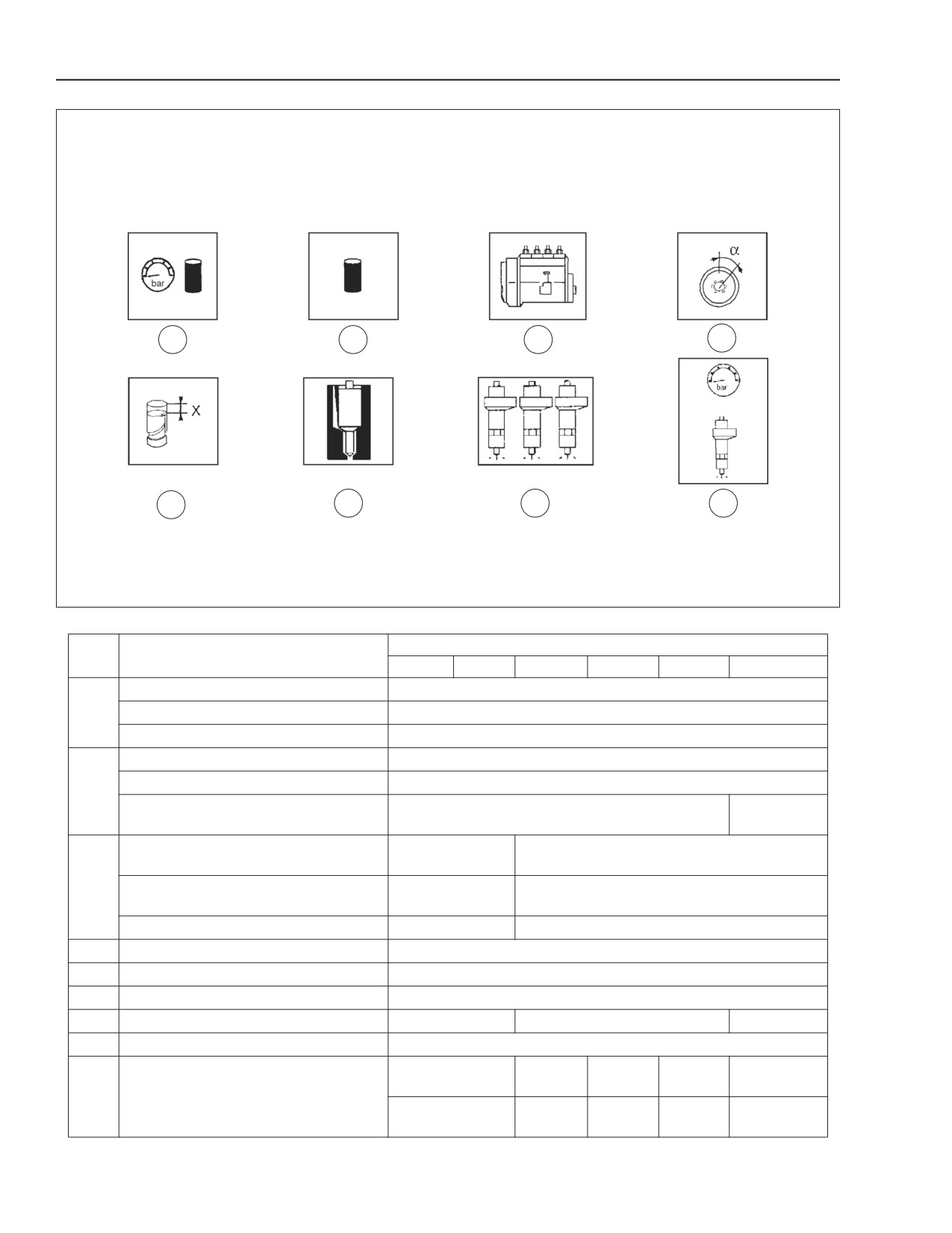
BS06K014
Figure 2-6
REF.
667TA
ENGINE TYPE
NO.
EEG
EEC
EBF
EED
EBD
EDJ
Lubrication.
Forced by means of gear pump. Oil psi control valve.
12
Oil pressure with hot engine: at idle rpm.
1.2 bar (17.4 psi)
Oil pressure with hot engine: at peak rpm.
3.8 bar (55.1 psi)
Cooling.
Fluid
Water pump drive.
Belt
13
83 to98° C
Thermostat start of opening temperature.
79 to 83° C (174 to 181° F)
(181 to 208° F)
No Information
Oil capacity 1st filling.
No Information Available
Available
14
No Information
Oil capacity engine sump.
No Information Available
Available
Oil capacity engine sump + filter.
17 litres (18 qt.)
19 litres (20 qt.)
15
Feeding Bosch-type injection
High pressure Common Rail
16
Pump setting
No Information Available
17
Start of delivery
No Information Available
18
Type of injector
CRIN 1
CRIN 2
CRIN 2
19
Injection sequence
1 -5 -3 -6 -2 -4
250 - 1600
250 -1400
250 -1600
--
--
bar
bar
bar
20
Injection pressure
3626 -
3626 -
3626 -
--
--
23206 psi
20305 psi
23206 psi
2-8
Issued 11-06
Bur
87519804 NA
ENGINE REPAIR MANUAL
CHAPTER 2 - 667TA ENGINE OVERHAUL
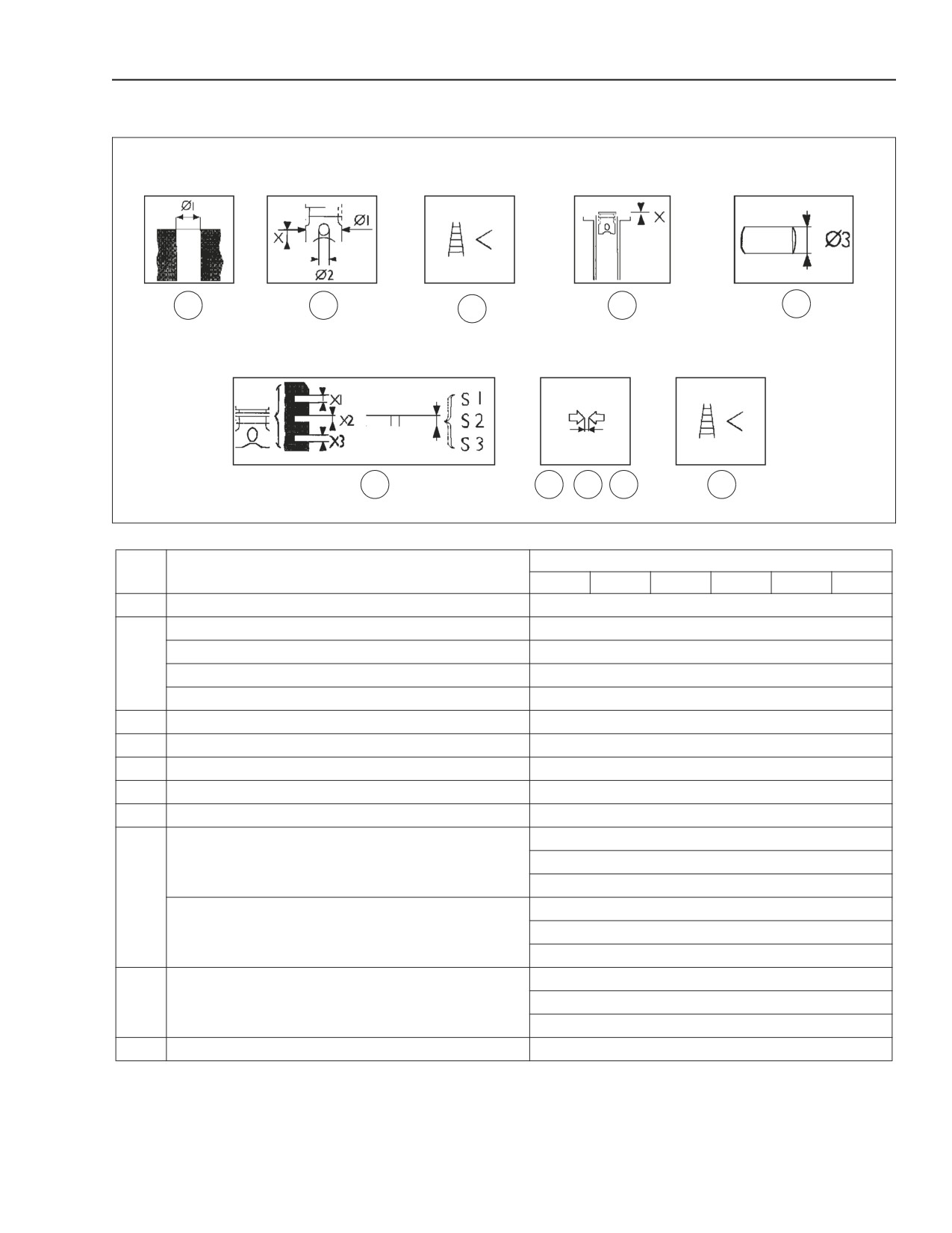
CRANK GEAR COMPONENTS AND CYLINDER ASSEMBLY
1
2
4
5
6
8
3
7
9
10
BS06K015
Figure 2-7
REF.
667TA
ENGINE TYPE
NO.
EEG
EEC
EBF
EED
EBD
EDJ
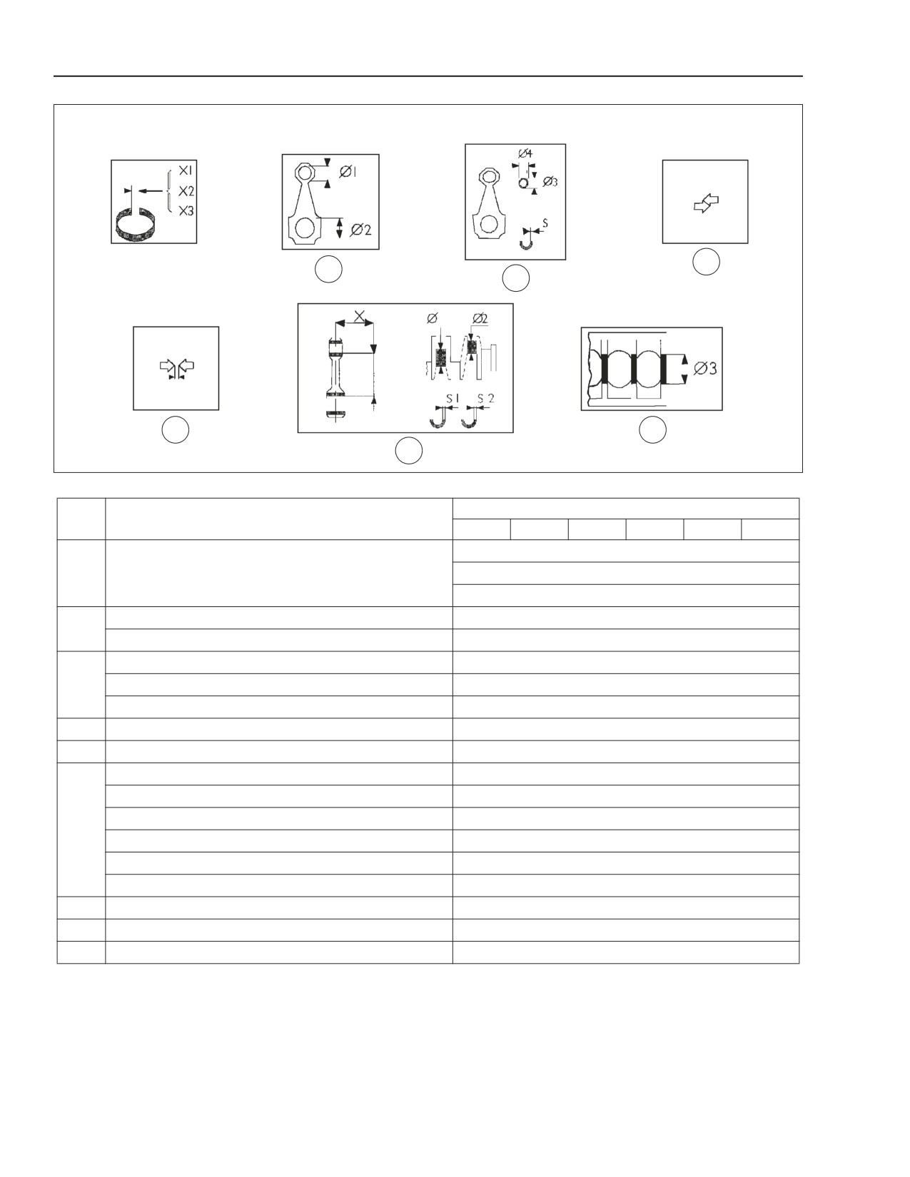
1
Cylinder liners.
104.000 to 104.024 mm. (4.0945 to 4.0954 in.)
Pistons:
Supplied as spares
Measurement dimension.
X=
49.5 mm. (1.948813 in.)
2
Outer diameter.
Ø1=
103.759 to 103.777 mm. (4.0850 to 4.0857 in.)
Pin seat.
Ø2=
38.010 to 38.016 mm. (1.4965 to 1.4967 in.)
3
Piston - cylinder liners.
0.235 to 0.273 mm. (0.0093 to 0.0107 in.)
4
Piston diameter.
Ø=
0.4 mm. (0.0157 in.)
5
Protrusion of pistons from crankcase.
No Information Available
6
Piston pin.
Ø3=
37.994 to 38.000 mm. (1.4958 to 1.4961 in.)
7
Piston pin-Pin seat.
0.01 to 0.022 mm. (0.0004 to 0.0009 in.)
X1=
2.705 to 2.735 mm. (0.1065 to 0.1077 in.)
Piston ring grooves
X2=
2.420 to 2.440 mm. (0.0953 to 0.0961 in.)
(measured on Ø of 101 mm 3.976366 in.)
X3=
4.03 to 4.05 mm. (0.1587 to 0.1594 in.)
8
S1=
2.560 to 2.605 mm. (0.1008 to 0.1026 in.)
Piston rings
S2=
2.350 to 2.380 mm. (0.0925 to 0.0937 in.)
(measured 1.5 mm 0.05905494 in. away from external Ø).
S3=
3.977 to 3.990 mm. (0.1566 to 0.1571 in.)
1=
0.100 to 0.175 mm. (0.0039 to 0.0069 in.)
9
Piston rings - Slots.
2=
0.04 to 0.09 mm. (0.0016 to 0.0035 in.)
3=
0.04 to 0.083 mm. (0.0016 to 0.0033 in.)
10
Piston rings.
0.4mm. (0.0157 in.)
87519804 NA
Issued 11-06
Bur
2-9
ENGINE REPAIR MANUAL
CHAPTER 2 - 667TA ENGINE OVERHAUL
11
14
12
13
15
17
16
BS06K016
Figure 2-8
REF.
667TA
ENGINE TYPE
NO.
EEG
EEC
EBF
EED
EBD
EDJ
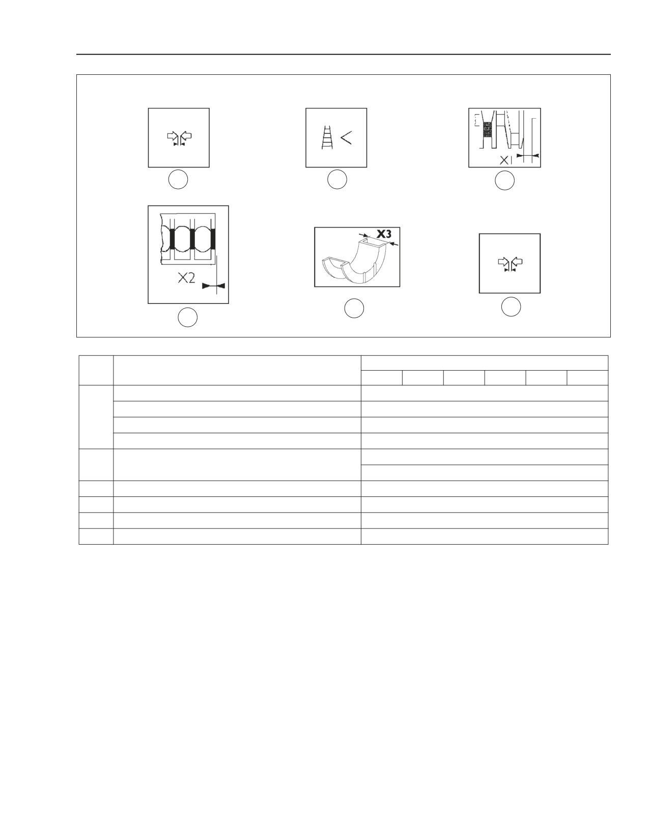
X1=
0.30 to 0.40 mm. (0.0118 to 0.0157 in.)
11
Piston ring gaps in cylinder liner.
X2=
0.60 to 0.80 mm. (0.0236 to 0.0315 in.)
X3=
0.30 to 0.55 mm. (0.0118 to 0.0217 in.)
Connecting rod small-end bearing seat.
Ø1=
40.987 to 41.553 mm. (1.6137 to 1.6147 in.)
12
Connecting rod bearing seat.
Ø2=
72.987 to 73.013 mm. (2.8735 to 2.8745 in.)
Connecting rod small-end bearing diameter.
13
Outer
Ø4=
41.279 to 41.553 mm. (1.6252 to 1.6359 in.)
Inner
Ø3=
38.019 to 38.033 mm. (1.4968 to 1.4974 in.)
14
Connecting rod small-end bearing seat.
0.266 to 0.566 mm. (0.0105 to 0.0223 in.)
15
Piston pin - bearing.
0.019 to 0.039 mm. (0.0007 to 0.0015 in.)
Measurement dimension.
No Information Available
Maximum error on connecting rod axis parallelism.
No Information Available
Journals
Ø1=
82.990 to 83.010 mm. (3.2673 to 3.2681 in.)
16
Crank pins
Ø2=
68.987 to 69.013 mm. (2.7160 to 2.7170 in.)
Main half bearings (supplied as spares).
S1=
2.456 to 2.464 mm. (0.0967 to 0.0970 in.)
Connecting rod half bearings.
S2=
1.955 to 1.968 mm. (0.0770 to 0.0775 in.)
17
Main bearing- journals
Numbers 1, 7
Ø3
87.982 to 88.008 mm. (3.4638 to 3.4649 in.)
Numbers 2, 3, 4, 5, 6
Ø3=
87.977 to 88.013 mm. (3.4637 to 3.4651 in.)
2-10
Issued 11-06
Bur
87519804 NA
ENGINE REPAIR MANUAL
CHAPTER 2 - 667TA ENGINE OVERHAUL
18
19
20
22
23
21
BS06K017
Figure 2-9
REF.
667TA
ENGINE TYPE
NO.
EEG
EEC
EBF
EED
EBD
EDJ
Half bearing- journals.
Numbers 1, 7
0.044 to 0.106 mm. (0.0017 to 0.0042 in.)
18
Numbers 2, 3, 4, 5, 6
0.041 to 0.103 mm. (0.0016 to 0.0041 in.)
Half bearing - crank pins.
0.039 to 0.111 mm. (0.0015 to 0.0044 in.)
+0.250 mm. (0.0098 in.)
Main half bearings
19
Connecting rod half bearings.
+0.500 mm. (0.0197 in.)
20
Main journal of thrust bearing.
X1=
37.475 to 37.545 mm. (1.4754 to 1.4781 in.)
21
Main bearing housing of thrust bearing.
X2=
25.980 to 26.480 mm. (1.0228 to 1.0425 in.)
22
Shoulder half ring.
X3=
37.280 to 37.380 mm. (1.4677 to 1.4716 in.)
23
Crankshaft shoulder.
0.095 to 0.265 mm. (0.0037 to 0.0104 in.)
87519804 NA
Issued 11-06
Bur
2-11
ENGINE REPAIR MANUAL
CHAPTER 2 - 667TA ENGINE OVERHAUL
VALVE GEAR - CYLINDER ASSEMBLY
1
3
3
4
5
6
7
8
BS06K018
Figure 2-10
REF.
667TA
ENGINE TYPE
NO.
EEG
EEC
EBF
EED
EBD
EDJ
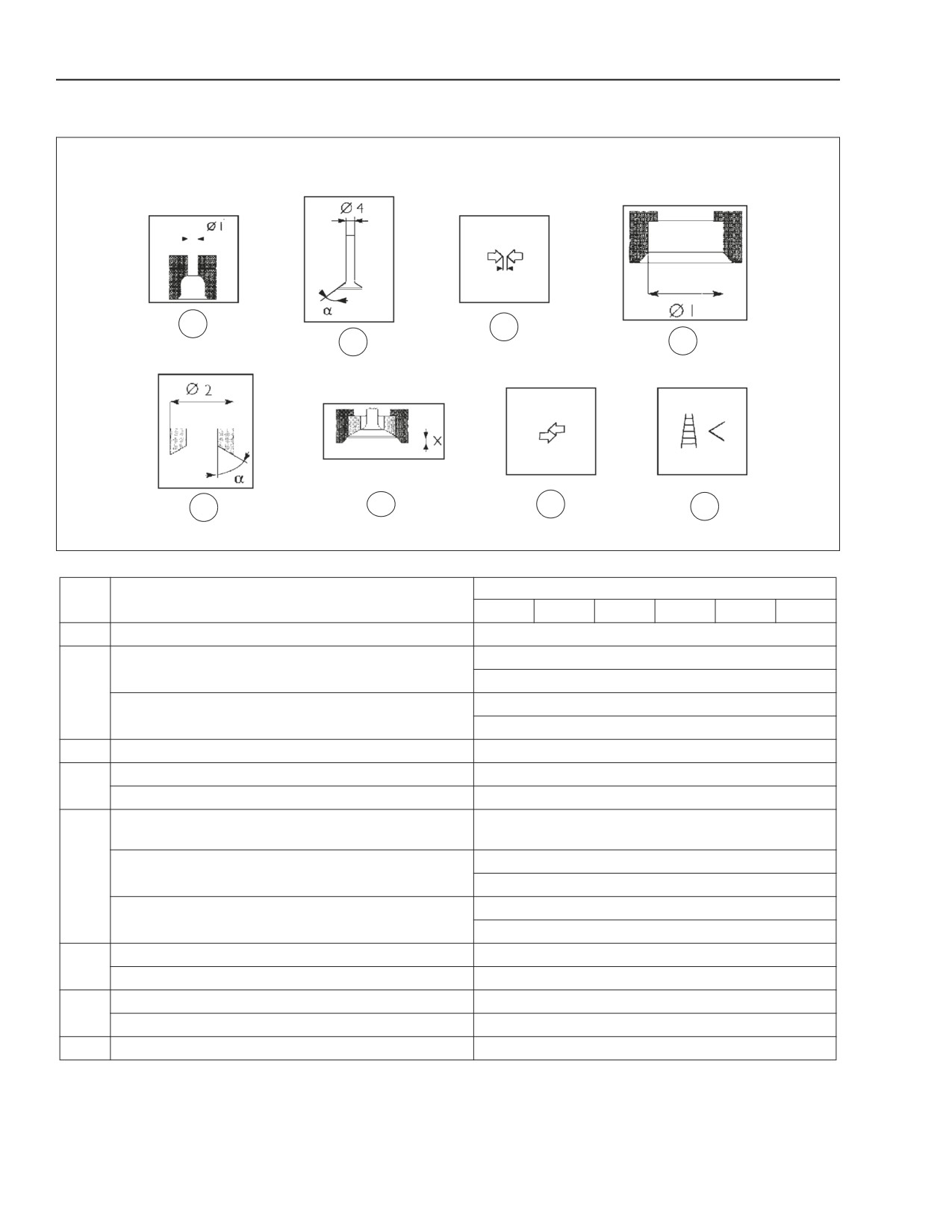
1
Valve guide seats on cylinder head.
Ø1=
7.042 to 7.062 mm. (0.2772 to 0.2780 in.)
Ø4=
6.970 to 6.999 mm. (0.2744 to 0.2756 in.)
Valves - Intake.
angle=
60° ± 0.25°
2
Ø4=
6.970 to 6.999 mm. (0.2744 to 0.2756 in.)
Valves - Exhaust.
angle=
45° ± 0.25°
3
Valve stem and respective guide.
0.043 to 0.092 mm. (0.0017 to 0.0036 in.)
seat on head for valve seat. - Intake.
34.837 to 34.863 mm. (1.3715 to 1.3725 in.)
4
seat on head for valve seat. - Exhaust.
34.837 to 34.863 mm. (1.3715 to 1.3726 in.)
Valve seat outer diameter; angle of valve seats on cylinder
head.
Ø2=
34.917 to 34.931 mm. (1.3747 to 1.3752 in.)
5
Intake.
angle=
60°
Ø2=
34.917 to 34.931 mm. (1.374681 to 1.375232 in)
Exhaust.
angle=
45°
Recessing. Intake valve
0.590 to 1.110 mm. (0.0232 to 0.0437 in.)
6
Recessing. Exhaust valve
0.960 to 1.480 mm. (0.0378 to 0.0583 in.)
Between valve seat and head- Intake
0.054 to 0.094 mm. (0.0021 to 0.0037 in.)
7
Between valve seat and head- Exhaust
0.054 to 0.094 mm. (0.0021 to 0.0037 in.)
8
Valve seats
No Information Available
2-12
Issued 11-06
Bur
87519804 NA
ENGINE REPAIR MANUAL
CHAPTER 2 - 667TA ENGINE OVERHAUL
12
13
14
10
11
9
16
15
18
22
19
21
20
17
BS06K019
Figure 2-11
REF.
667TA
ENGINE TYPE
NO.
EEG
EEC
EBF
EED
EBD
EDJ
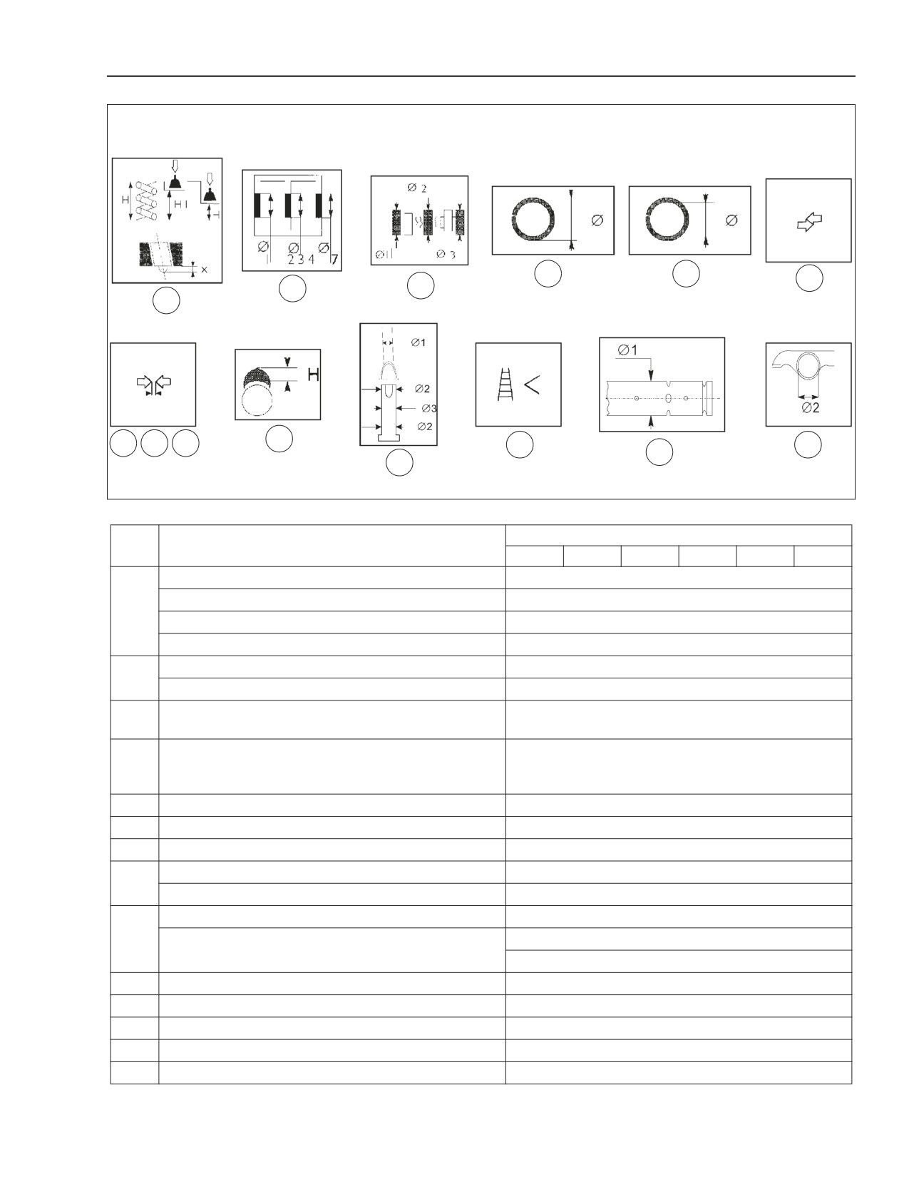
Valve spring height: Free spring.
H=
47.750 mm. (1.8799 in.)
Under load of: 339.8 N ± 19 N (76.4 lbf ± 4.3 lbf).
H1=
35.330 mm. (1.3909 in.)
9
Under load of: 741.0 N ± 39 N (166.6 lbf ± 8.8 lbf).
H2=
25.200 mm. (0.9921 in.)
Injector protrusion.
X= Not Adjustable
Seats for camshaft bearing.- number - 7
Ø 7=
59.222 to 59.248 mm. (2.3316 to 2.3326 in.)
10
Seats for camshaft bearings.- numbers - 1, 2, 3, 4, 5, 6
Ø 1-6=
54.089 to 54.139 mm. (2.1295 to 2.1315 in.)
Ø 1, 2, 3, 4, 5, 6, 7=
53.995 to 54.045 mm.
11
Camshaft main journals:
1 through 7
(2.1258 to 2.1277 in.)
External diameter of the bearing for the camshaft with a
12
Ø= 59.222 to 59.248 mm. (2.3316 to 2.3326 in.)
load of 3.3 kNm (741.8695 lbf).
13
Camshaft bearing inner diameter.
Ø=
54.083 to 54.147 mm. (2.1292 to 2.1318 in)
14
Bearing and seats in crankcase.
0.113 to 0.165 mm. (0.0044 to 0.0065 in.)
15
Bearing and main journals.
0.038 to 0.162 mm. (0.0015 to 0.0064 in.)
Useful cam lift- Intake.
6.045 mm. (0.2380 in.)
16
Useful cam lift- Exhaust.
7.239 mm. (0.2850 in.)
Tappet plate seat in crankcase.
Ø1=
16.000 to 16.030 mm. (0.6299 to 0.6311 in.)
17
Ø2=
15.924 to 15.954 mm. (0.6269 to 0.6281 in.)
Tappet plate outside diameter.
Ø3=
15.960 to15.970 mm. (0.6283 to 0.6287 in.)
18
Between tappets and seat.
0.030 to 0.070 mm. (0.0012 to 0.0028 in.)
19
Tappets.
No Information Available
20
Rocker arm shaft.
Ø1=
21.965 to 21.977 mm. (0.8648 to 0.8652 in.)
21
Rocker arms
Ø2=
22.001 to 22.0027 mm. (0.86618 to 0.86625 in.)
22
Between rocker arm and spindle
0.024 to 0.0377 mm. (0.0009 to 0.0015 in.)
GRAPHIC_1D
Figure 2-12
87519804 NA
Issued 11-06
Bur
2-13
ENGINE REPAIR MANUAL
CHAPTER 2 - 667TA ENGINE OVERHAUL
TORQUE SPECIFICATIONS
PART
TORQUE - Nm (lb.-ft.)
Cylinder head fastening bolt.
1st phase.
Bolts M12x1.75x70
45 to 55 Nm (33.2 to 40.6 lb.-ft.)
Bolts M12x1.75x140
35 to 45 Nm (25.8 to 33.2 lb.-ft.)
Bolts M12x1.75x180
(pre lubricate with oil)
65 to 75 Nm (47.9 to 55.3 lb.-ft.)
2nd phase additional rotation
90 degrees
3rd phase (only for bolts 140 and 180 mm long additional rotation)
90 degrees
Main bearing Caps.
1st phase. (pre lubricate with oil)
44 to 56 Nm (32.5 to 41.3 lb.-ft.)
2nd phase
74 to 86 Nm (54.6 to 63.4 lb.-ft.)
3rd phase. additional rotation
90 ±5 degrees
Connecting rod cap fasting bolts.
1st phase. (pre lubricate with oil
55 to 65 Nm (40.6 to 47.9 lb.-ft.)
2nd phase. additional rotation
60 ±5 degrees
Engine flywheel fastening bolts.
1st phase
26 to 34 Nm (19.2 to 25.1 lb.-ft.)
2nd phase. additional rotation
60 ± 5 degrees
Nut securing connector for injector supply
45 to 50 Nm (33.2 to 36.9 lb.-ft.)
Sump (oil pan)
20 to 28Nm (14.8 to 20.7lb.-ft.)
Fuel filter
Contact + 3/4 turn
Injection pump gear cover fastening bolts
20 to 30 Nm (14.8 to 22.1 lb.-ft.)
Valve gear cover and case fastening bolts
20 to 28Nm (14.8 to 20.7 lb.-ft.)
Intake manifold fastening bolts
20 to 28 Nm (14.8 to 20.7 lb.-ft.)
Fuel pump fastening bolts
20 to 30 Nm (14.8 to 22.1 lb.-ft.)
Exhaust manifold fastening bolts
48 to 58 Nm (35.4 to 42.8 lb.-ft.)
Valve cover fastening nuts
20 to 28 Nm (14.8 to 20.7 lb.-ft.)
Rocker arm support fastening bolts
31 to 41Nm (22.9 to 30.2 lb.-ft.)
Nut for rocker arm adjusting bolt
20 to 28 Nm (14.8 to 20.7 lb.-ft.)
Bolts fastening the pulley on the crankshaft.
1st phase
45 to 55 Nm (33.2 to 40.6 lb.-ft.)
2nd phase additional rotation
90 ±5 degrees
Cam shaft shoulder plate fastening bolts
20 to 28 Nm (14.8 to 20.7 lb.-ft.)
Fan support fastening bolts
20 to 30 Nm (14.8 to 22.1 lb.-ft.)
Injection pump fastening bolts
7 to 17 Nm (5.2 to 12.5 lb.-ft.)
Fan pulley fastening bolts
37 to 49 Nm (27.3 to 36.1 lb.-ft.)
Turbocharger fastening bolts
20 to 30 Nm (14.8 to 22.1 lb.-ft.)
Starter motor fastening bolts
37 to 49 Nm (27.3 to 36.1 lb.-ft.)
Alternator fastening bolts
37 to 49 Nm (27.3 to 36.1 lb.-ft.)
Water pump fastening bolts
20 to 28 Nm (14.8 to 20.7 lb.-ft.)
Oil filter
Contact + 3/4 turn
Belt tensioner fastening bolts
37 to 49 Nm (27.3 to 36.1 lb.-ft.)
Water Oil cooler (heat exchanger) for EDC7UC31 control unit
M6 bolt
8 to 12 Nm (5.9 to 8.9 lb.-ft.)
M8 bolt
20 to 28 Nm (14.8 to 20.7 lb.-ft.)
Oil pump and front cover fastening bolts
1st stage
7 to 9 Nm (5.2 to 6.6 lb.-ft.)
2nd stage
20 to 28 Nm (14.8 to 20.7 lb.-ft.)
Cylinder bore lubrication jets fastening bolt
12 to 18 Nm (8.9 to 13.3 lb.-ft.)
Common Rail fastening bolts
20 to 28 Nm (14.8 to 20.7 lb.-ft.)
Boost temperature/pressure sensor on intake manifold
5 to 7 Nm (3.7 to 5.2 lb.-ft.)
Engine oil level sensor bolt
10 to 14 Nm (7.3 to 10.3 lb.-ft.)
Turbocharger to exhaust manifold fastening bolts
37 to 49 Nm (27.3 to 36.1 lb.-ft.)
Wiring duct securing bolt M6
8 to 12 Nm (5.9 to 8.9 lb.-ft.)
Support for electrical wiring for injector power supply bolt
20 to 28 Nm (14.8 to 20.7 lb.-ft.)
2-14
Issued 11-06
Bur
87519804 NA
ENGINE REPAIR MANUAL
CHAPTER 2 - 667TA ENGINE OVERHAUL
Fuel filter bracket
M12 bolt
69 to 85 Nm (50.9 to 62.7 lb.-ft.)
M8 bolt
20 to 28 Nm (14.8 to 20.7 lb.-ft.)
Flywheel casing
M10 bolt
75 to 95 Nm (55.3 to 70.1 lb.-ft.)
M12 bolt
44 to 55Nm (32.5 to 40.6 lb.-ft.)
Camshaft sensor fastening bolt
6 to 10 Nm (4.4 to 7.4 lb.-ft.)
Crankshaft sensor fastening bolt
6 to 10 Nm (4.4 to 7.4 lb.-ft.)
Engine coolant temperature sensor fastening bolt
17 to 23 Nm (12.5 to 17.0 lb.-ft.)
Oil pressure/temperature sensor fastening bolt
5 to 7 Nm 3.7 to 5.2 lb.-ft.)
Fuel pressure sensor fastening bolt
30 to 40 Nm (22.1 to 29.5 lb.-ft.)
Fuel temperature sensor fastening bolt
17 to 23 Nm (12.5 to 17.0 lb.-ft.)
87519804 NA
Issued 11-06
Bur
2-15
ENGINE REPAIR MANUAL
CHAPTER 2 - 667TA ENGINE OVERHAUL
SPECIAL TOOLS
380000158
1-6 Nm dyanametric (torque) screw driver for calibrating injector solenoid valve.
connector check nut (Common Rail).
380000665
Tool for removing the crankshaft front seal.
380000663
Tool for removing the crankshaft rear seal.
380000671
Injector extracting tool.
380000666
Coupler for installing the crankshaft front seal.
380000664
Coupler for installing the crankshaft rear seal.
(except engines: 667TA/EBF - 667TA/EED).
380000988
Tool for rotating the engine flywheel (except engines 667TA/EBF - 667TA/EED).
380001099
Tool for removing injectors.
2-16
Issued 11-06
Bur
87519804 NA
ENGINE REPAIR MANUAL
CHAPTER 2 - 667TA ENGINE OVERHAUL
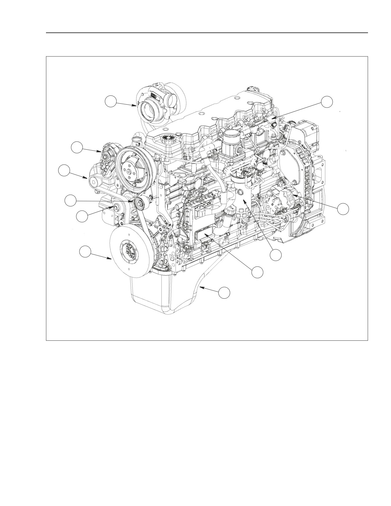
667TA ENGINES
1
11
2
3
4
10
5
6
9
8
7
BS06K020
Figure 2-13
-
1. TURBOCHARGER
5. WATER PUMP
9. FUEL FILTER
2. AUTOMATIC BELT TENSIONER
6. DAMPER FLYWHEEL
10. HIGH PRESSURE PUMP
3. ALTERNATOR
7. OIL PAN (SUMP)
11. COMMON RAIL
4. FIXED GUIDE PULLEY
8. ELECTRONIC CONTROL UNIT
87519804 NA
Issued 11-06
Bur
2-17
ENGINE REPAIR MANUAL
CHAPTER 2 - 667TA ENGINE OVERHAUL
DESCRIPTION OF MAIN ENGINE COMPONENTS
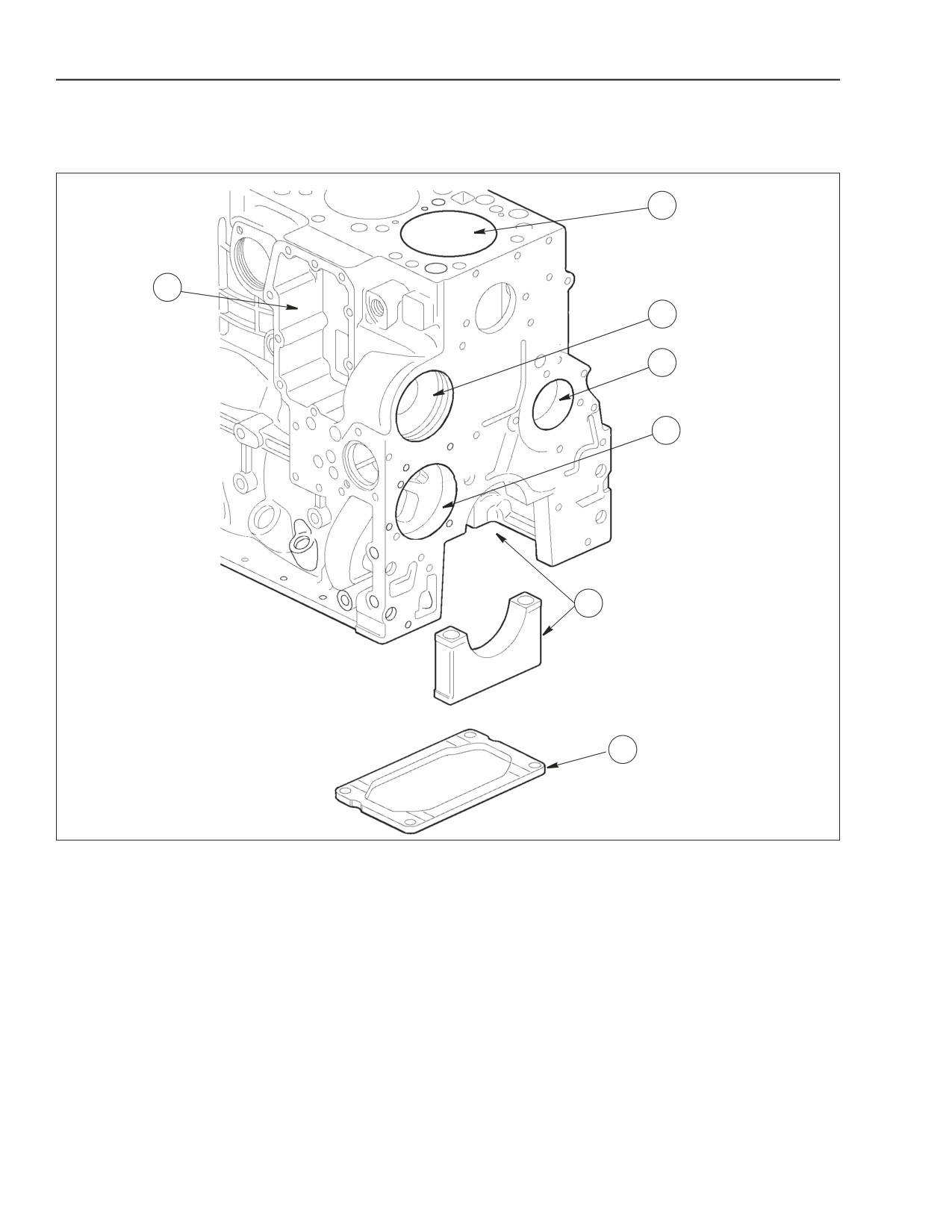
ENGINE BLOCK
1
7
2
3
4
5
6
BS06K021
Figure 2-14
3. SEATS FOR CAMSHAFT BEARINGS AND
1. CYLINDER BORE
5. MAIN BEARING HOUSINGS
7. WATER/OIL COOLER
TAPPETS
2. WATER PUMP
4. OIL PUMP
6. CRANKSHAFT STIFFING PLATE
The engine block consists of a cast iron structure
containing the cylinder bores (1), the main bearing
housings (5), and the following seats: for camshaft
bearings (3), for the water/oil cooler (7), water pump
(2), and oil pump (4). The block also incorporates the
water jackets for cooling and the oil galleys for
lubrication.
The crankshaft stiffening plate (6) is installed on the
crankshaft main bearing cap bolts into the engine
block and ensures greater resistance to mechanical
stress.
2-18
Issued 11-06
Bur
87519804 NA
ENGINE REPAIR MANUAL
CHAPTER 2 - 667TA ENGINE OVERHAUL
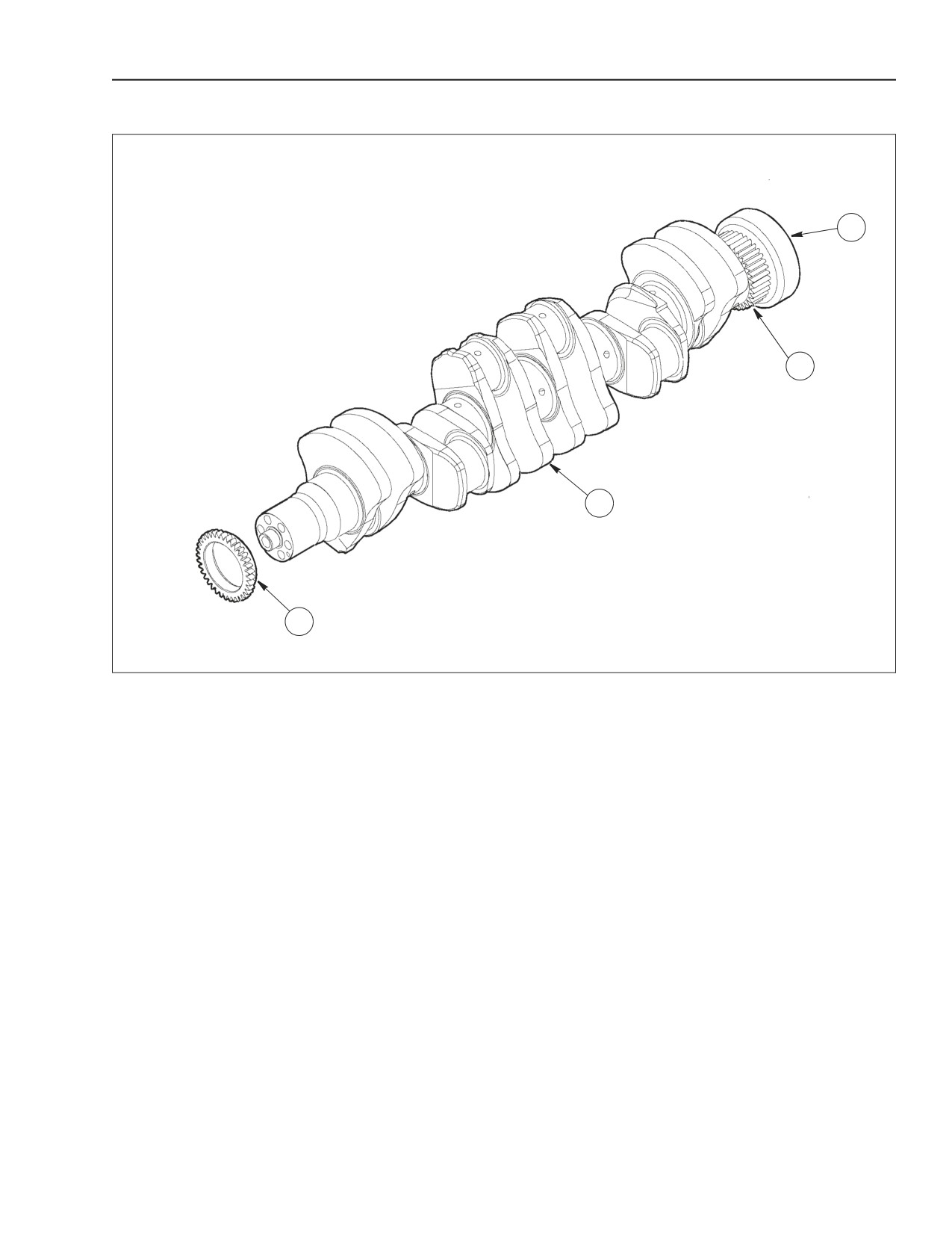
CRANKSHAFT
4
3
2
1
BS06K022
Figure 2-15
1. OIL PUMP DRIVE GEAR
2. CRANKSHAFT
3.
TIMING DRIVE GEAR
4. FLYWHEEL ATTACHMENT HUB
The crankshaft is made of steel and rests on seven
CRANKSHAFT OIL SEALS
induction hardened bearing journals. Drilled inside
The front and rear seals are box type with radial seal.
the crankshaft are a series of lubricating oil ducts.
Remove with special tools 380000665 and
The following items are pressed onto the front of the
380000663. Install with special tools 380000666 and
crankshaft: oil pump drive gear (1), speed sensor
380000664.
wheel, the vibration damper, and auxiliary equipment
drive pulley.
The following items are force-fitted onto the rear of
the crankshaft: timing gear (3), and the flywheel
mounting hub (4).
The main bearing shells are made of steel with a
antifriction alloy plating.
One of the main bearing shells is equipped with
shoulders to limit crankshaft endplay.
The timing drive gear (3) and the flywheel attachment
hub (4) are installed on the rear of the crankshaft with
a force-fit and cannot be replaced.
87519804 NA
Issued 11-06
Bur
2-19
ENGINE REPAIR MANUAL
CHAPTER 2 - 667TA ENGINE OVERHAUL
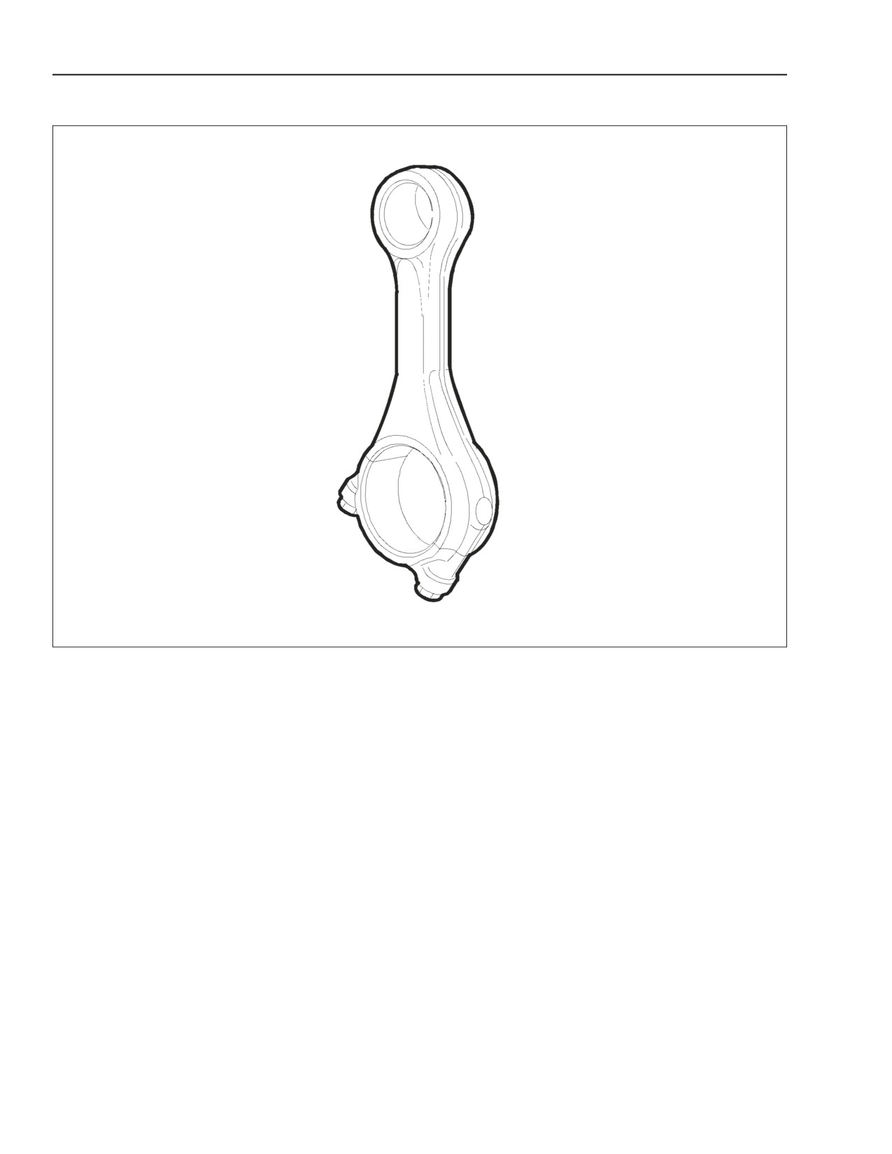
CONNECTING RODS
BS06K023
Figure 2-16
The connecting rods are forged steel, The
Each connecting rod is marked:
connecting rod crankshaft ends are made with an
• By a number on the connecting rod body and
oblique angle, with separation of rod and cap
on the cap indicating the match and the cylinder
obtained by means of the innovative fracture splitting
in which they are assembled.
system rather than the conventional machining
• By a letter on the connecting rod body
process.
indicating the weight class of the connecting rod
installed in production.
The connecting rod crankshaft bearing shells are
made of steel plated with an antifriction alloy.
2-20
Issued 11-06
Bur
87519804 NA
ENGINE REPAIR MANUAL
CHAPTER 2 - 667TA ENGINE OVERHAUL
PISTONS
1
2
3
4
BS06K024
Figure 2-17
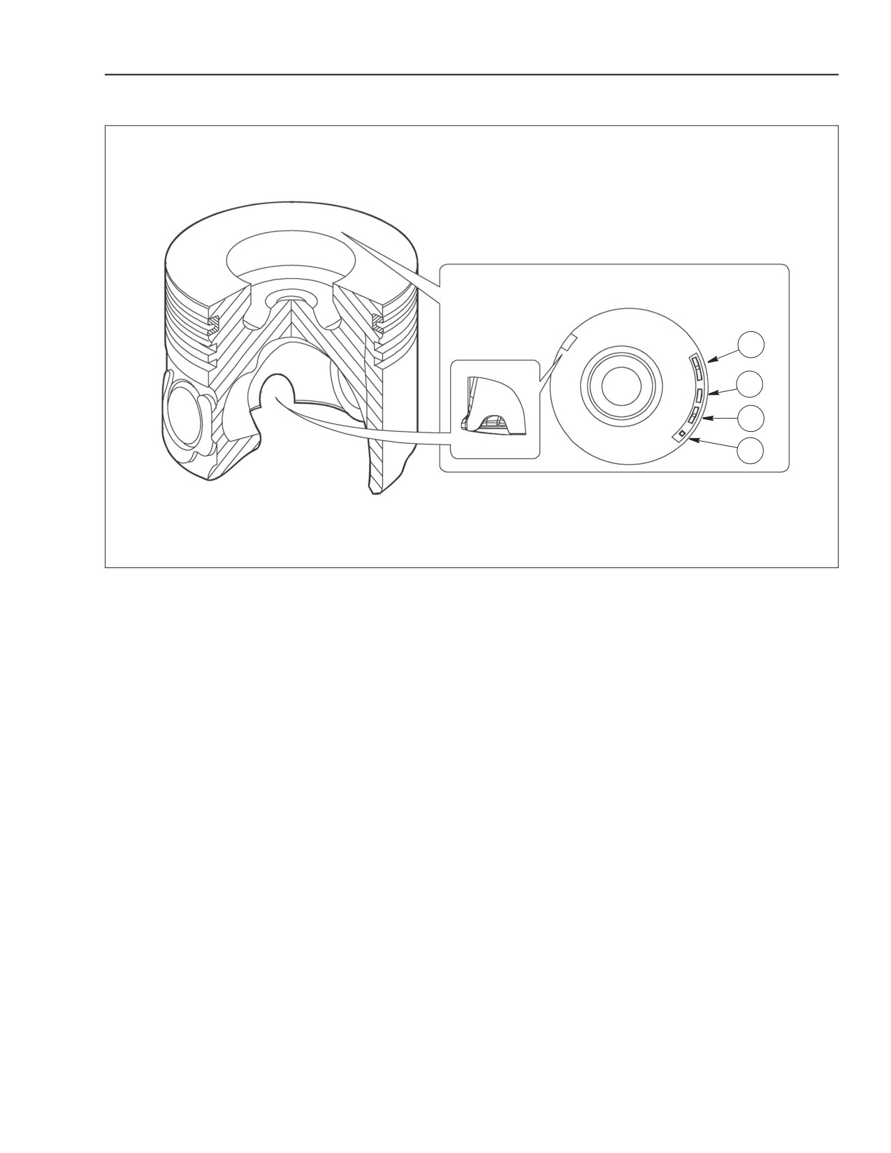
The piston crown features a high turbulence
The following reference data is engraved into the
combustion chamber. The underside of the piston
piston crown:
crown is cooled by engine oil delivered by a spray
1. Spare part number and design modification
nozzle installed in the crankcase.
number.
There are three piston ring grooves with different
2. Stamping
(facing the crankcase front side)
functions and different geometry.
indicating the mounting direction of the piston in
1st piston ring with trapezoidal (keystone)
the cylinder bore.
section, ceramic chrome plating.
3. Date of manufacture.
2nd piston ring with torsional conical rectangular
4. Stamping indicating 1st recess insert testing.
section.
3rd piston ring with double oil ring wiper with
internal spring.
87519804 NA
Issued 11-06
Bur
2-21
ENGINE REPAIR MANUAL
CHAPTER 2 - 667TA ENGINE OVERHAUL
CAMSHAFT
BS06K025
Figure 2-18
C
A
B
BS06K026
Figure 2-19
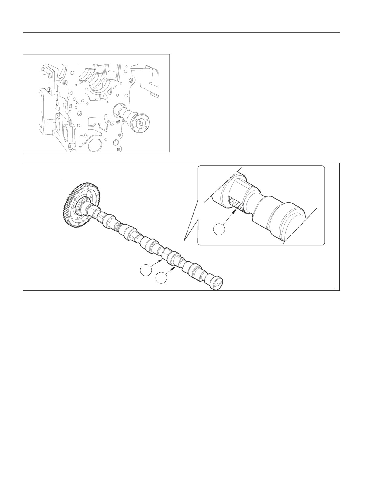
A. INTAKE VALVE LOBE
B. EXHAUST VALVE LOBE
C. EGR LOBE
The cam shaft is installed on 7 journals in the engine
The exhaust gas recirculation system (EGR), lowers
block.
the combustion temperature by decreasing the
concentration of oxygen in the combustion chamber.
The front and rear bearing housings are equipped
Creating an effective system to control the emission
with steel bearings plated with antifriction material
of NOx.
assembled by means of a foce-fit.
The internal EGR system exhaust cam design
There are two cam lobes per cylinder.
permits some of the exhaust gases to be returned
A. Intake valve lobe.
back into the engine cylinders. This type of EGR,
B. Exhaust valve lobe.
internal EGR is not provided with any electronically
controlled element. The system is always on. Its
The cam shaft is controlled directly by the crankshaft
configuration doesn’t need any additional elements
by means of rear spur tooth gears.
such as control valves, lines or heat exchangers.
The exhaust cam, beside the main lobe, has an
EGR EXHAUST GAS RECIRCULATION
additional lobe (C) compared to a cam without EGR.
SYSTEM
During the intake stroke of a cylinder this lobe
The exhaust gases can be partially returned back
permits a brief opening of the exhaust valve. This
into the cylinders to lower the maximum combustion
way recirculation is generated in the cylinder in the
temperature which is responsible for the production
cylinder during the intake stroke due to the greater
of nitrogen oxides (NOX).
pressure of the exhaust gases compared to the
intake gases.
2-22
Issued 11-06
Bur
87519804 NA
ENGINE REPAIR MANUAL
CHAPTER 2 - 667TA ENGINE OVERHAUL
VALVE CONTROL
10
1
9
2
3
4
5
6
8
7
BS06K027
Figure 2-20
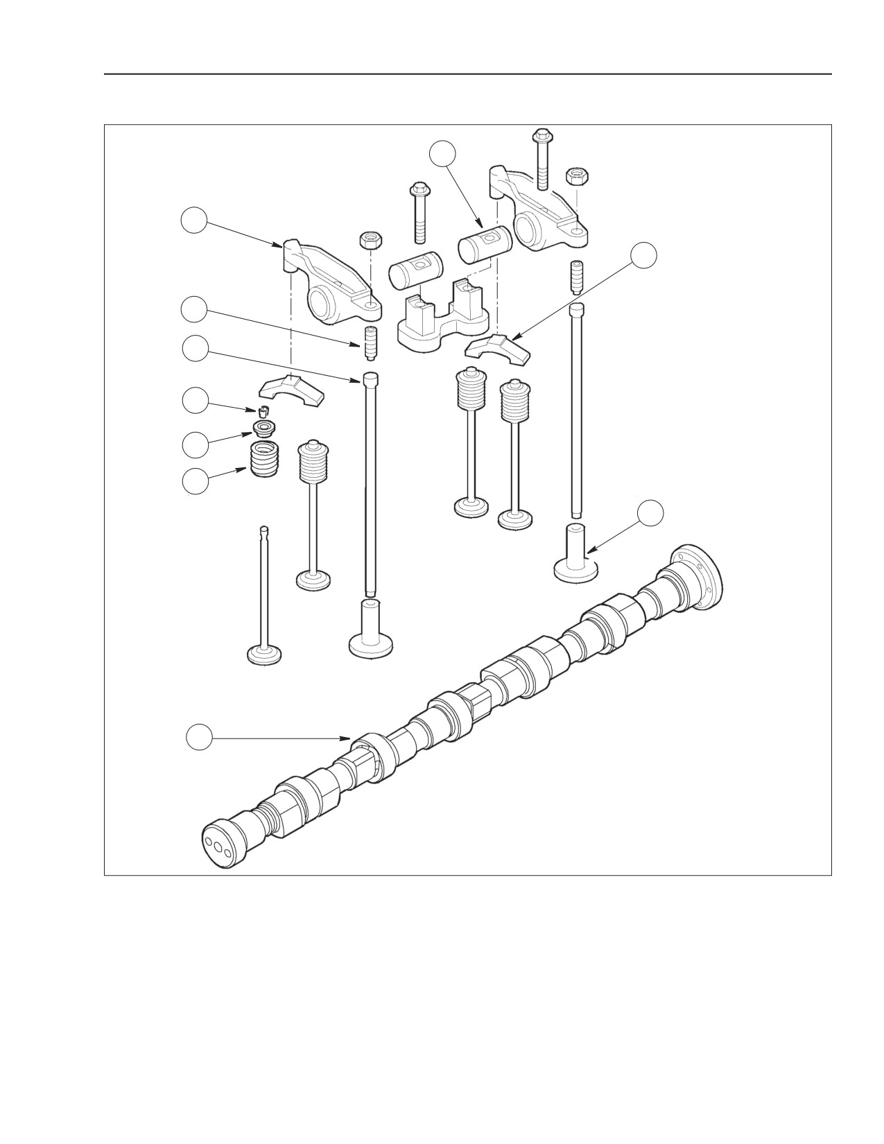
1. ROCKER ARM
3. PUSH ROD
5. SPRING SEAT
7. CAMSHAFT
9. VALVE BRIDGE
2. ADJUSTER SCREW
4. VALVE SPRING RETAINER (KEEPERS)
6. SPRING
8. TAPPET
10. ROCKER SPINDLE
87519804 NA
Issued 11-06
Bur
2-23
ENGINE REPAIR MANUAL
CHAPTER 2 - 667TA ENGINE OVERHAUL
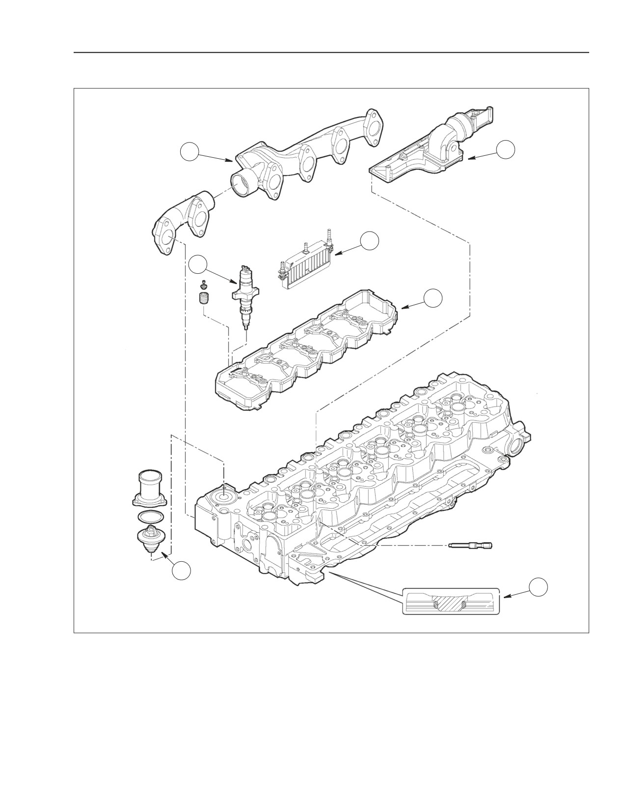
CYLINDER HEAD ENGINES: 667TA/EBF - 667TA/EBD - 667TA/EED
6
1
5
2
4
3
BS06K028
Figure 2-21
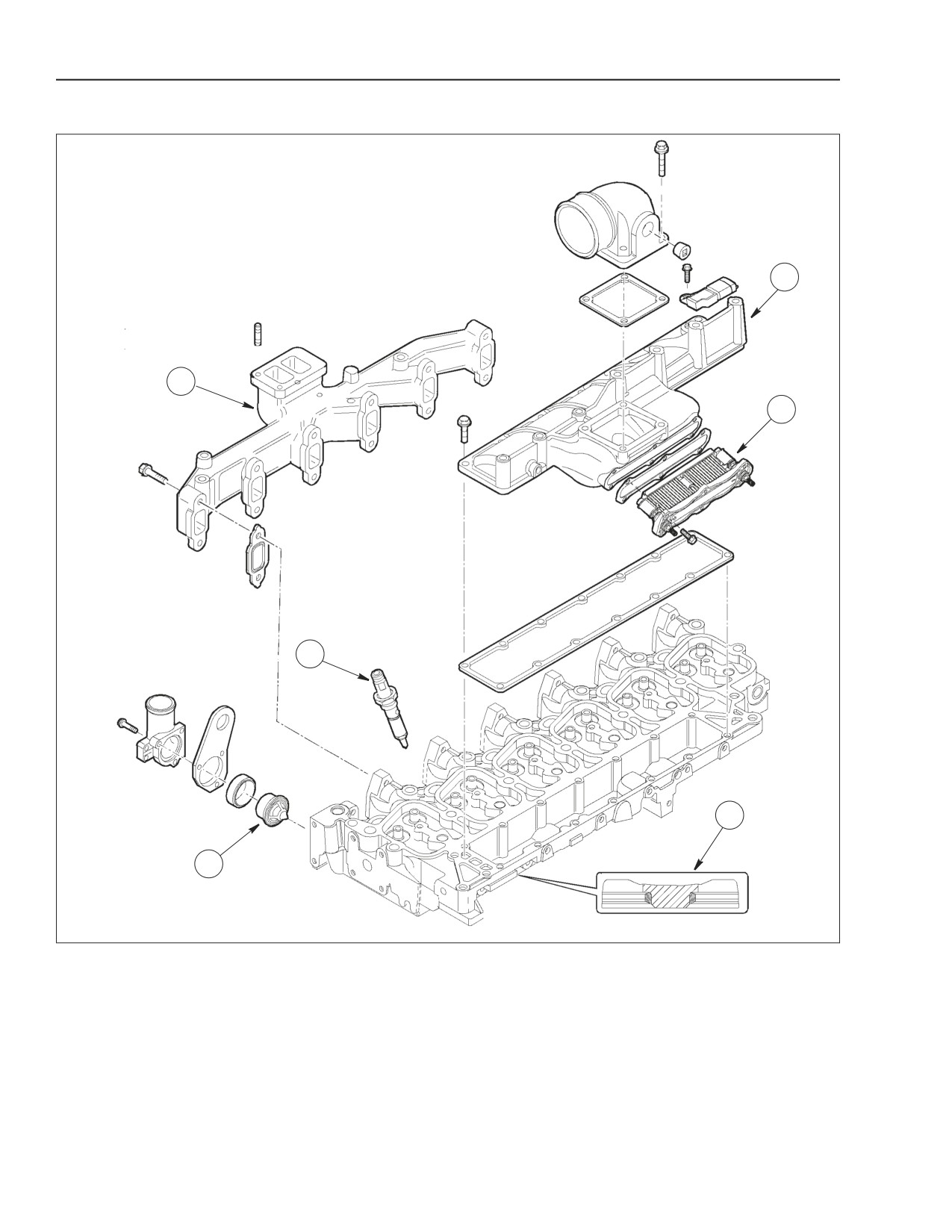
CYLINDER HEAD FOR ENGINES 667TA/EBF - 667TA/EBD - 667TA/EED
1. EXHAUST MANIFOLD
3. THERMOSTAT
5. GRID HEATER
2. INJECTOR
4. VALVE SEAT
6. INTAKE MANIFOLD
The cast iron cylinder head is machined to
The cylinder head is also fitted for the following
accommodate the following parts:
components to be installed on to the cylinder head.
• Valve seats (4).
• Exhaust manifold (1).
• Injectors (2).
• Intake manifold (6) with seat for grid heater (5).
• Thermostat (3).
2-24
Issued 11-06
Bur
87519804 NA
ENGINE REPAIR MANUAL
CHAPTER 2 - 667TA ENGINE OVERHAUL
CYLINDER HEAD ENGINES: 667TA/EEG - 667TA/EEC
1
7
6
2
5
3
4
BS06K029
Figure 2-22
1. EXHAUST MANIFOLD
3. THERMOSTAT
5. SUPPORT WITH WIRING HARNESS
7. INTAKE MANIFOLD
2. INJECTOR
4. VALVE SEAT
6. GRID HEATER
The cast iron cylinder head is machined to
The cylinder head is also fitted for the following
accommodate the following parts:
components to be inserted on to the head.
• valve seats (4).
• exhaust manifold (1).
• injectors (2).
• intake manifold (7) with seat for grid heater (6).
• thermostat (3).
87519804 NA
Issued 11-06
Bur
2-25
//////////////////////////////////////////