New Holland 667TA/EEG, 667TA/EEC, 667TA/EBF, 667TA/EED, 667TA/EBJ, 667TA/EDJ. ENGINE REPAIR MANUAL (2006) - page 2
ENGINE REPAIR MANUAL
CHAPTER 2 - 667TA ENGINE OVERHAUL
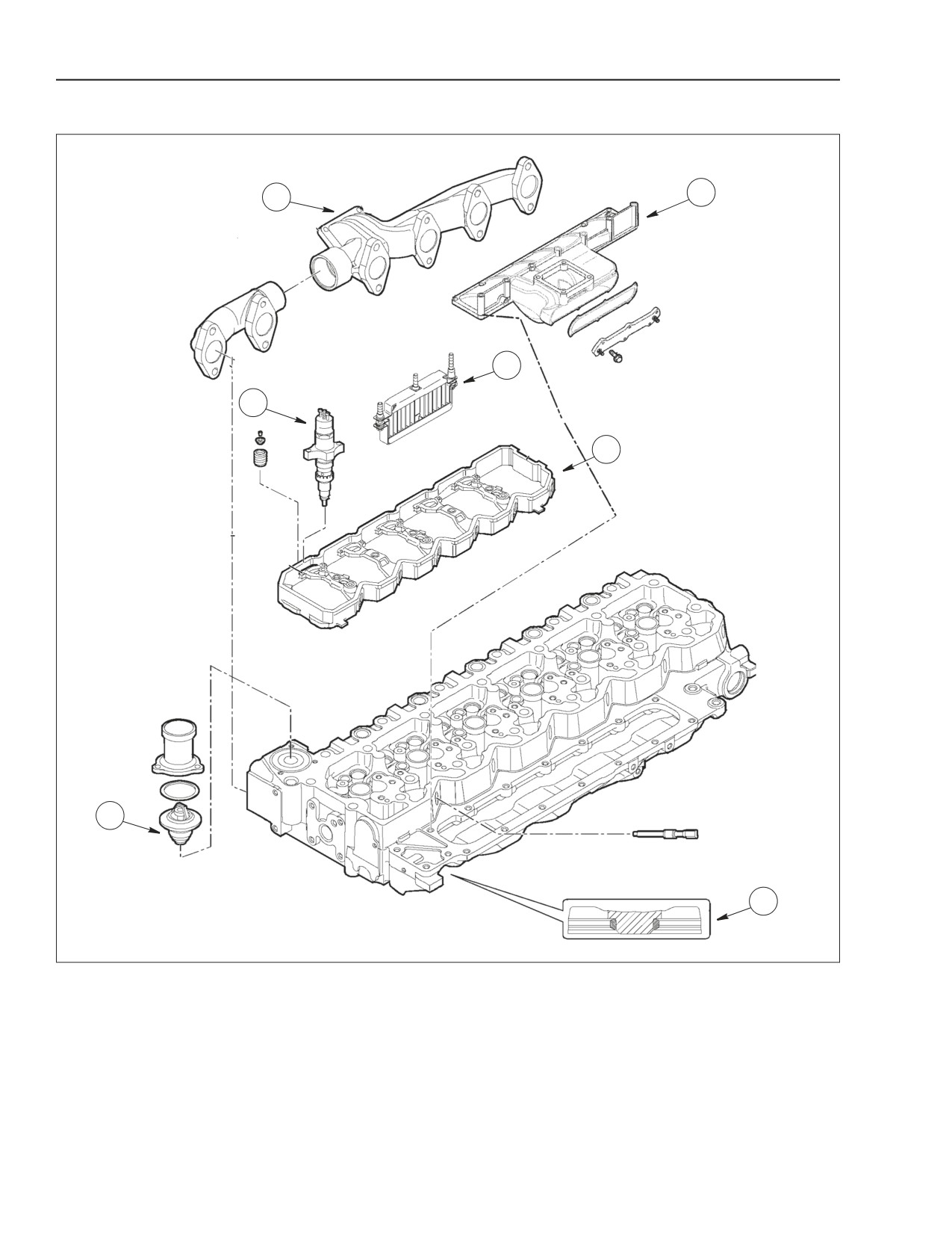
CYLINDER HEAD ENGINE: 667TA/EDJ
7
1
6
2
5
3
4
BS06K136
Figure 2-23
1. EXHAUST MANIFOLD
3. THERMOSTAT
5. SUPPORT WITH WIRING HARNESS
7. INTAKE MANIFOLD
2. INJECTOR
4. VALVE SEAT
6. GRID HEATER
The cast iron cylinder head is machined to
The cylinder head is also fitted for the following
accommodate the following parts:
components to be inserted on to the head.
• valve seats (4).
• exhaust manifold (1).
• injectors (2).
• intake manifold (7) with seat for grid heater (6).
• thermostat (3).
2-26
Issued 11-06
Bur
87519804 NA
ENGINE REPAIR MANUAL
CHAPTER 2 - 667TA ENGINE OVERHAUL
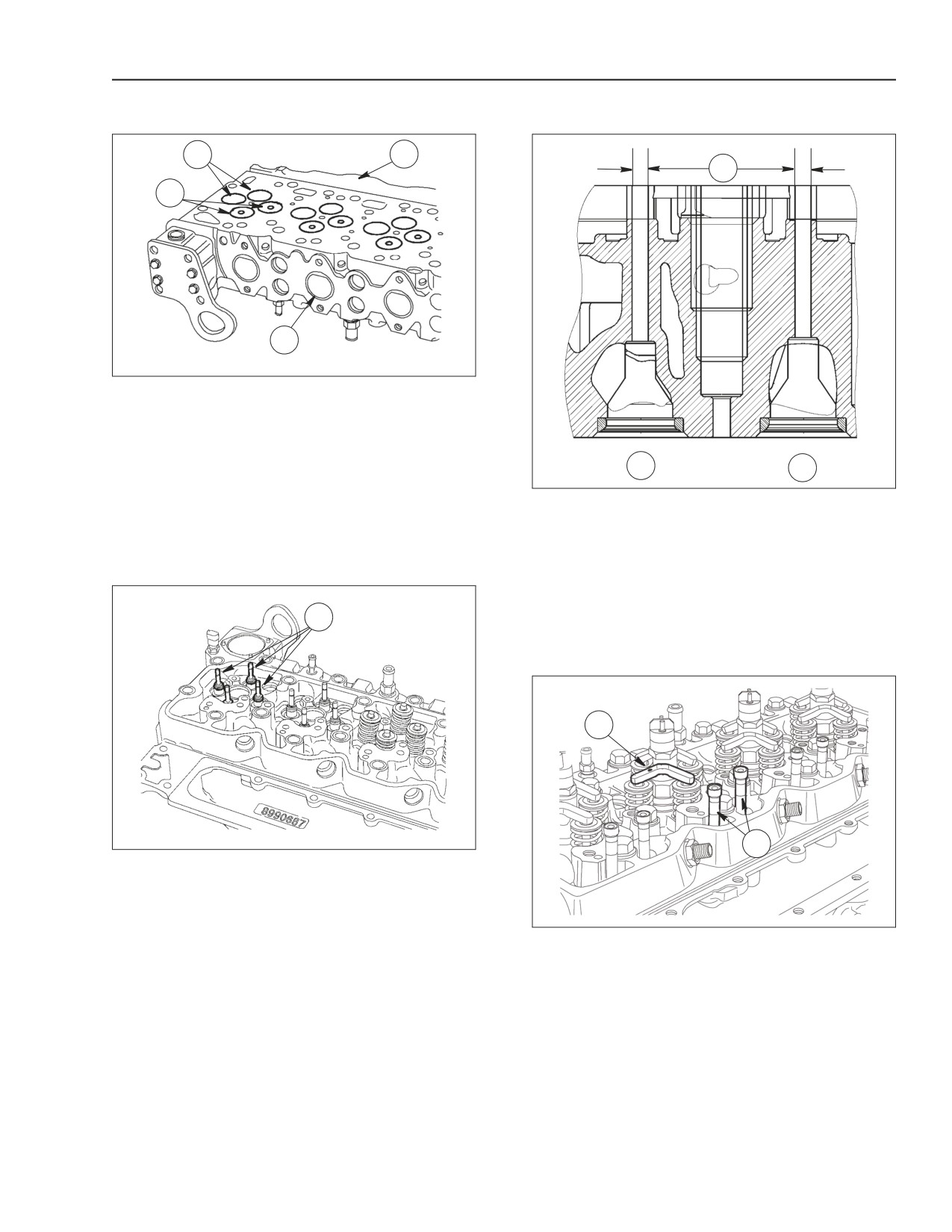
VALVES AND VALVE SEATS
1
3
1
2
4
BS06K030
Figure 2-24
1. INTAKE VALVE
3. INTAKE SIDE
2. EXHAUST VALVE
4. EXHAUST SIDE
Valve seats have the following angles:
2
3
Exhaust valves- 45°
BS06K032
Figure 2-26
Intake valves- 60°
1. 7.042 TO 7.062MM (0.277 TO 0.278 IN)
NOTE: Exhaust valves
(2) have a distinctive
2. INTAKE VALVES
3. EXHAUST VALVES
indentation at the center of the head of the valve.
The cylinder head does not have guide inserts. The
valve guide is machined directly into the head
casting.
1
VALVE BRIDGES
1
2
BS06K031
Figure 2-25
Oil seals (1) installed on the valve stems.
BS06K033
Figure 2-27
1. JUMPER
2. RODS
NOTE: When installing the cylinder head, the
orientation of valve bridges must be positioned with
marks (1) towards exhaust manifold.
87519804 NA
Issued 11-06
Bur
2-27
ENGINE REPAIR MANUAL
CHAPTER 2 - 667TA ENGINE OVERHAUL
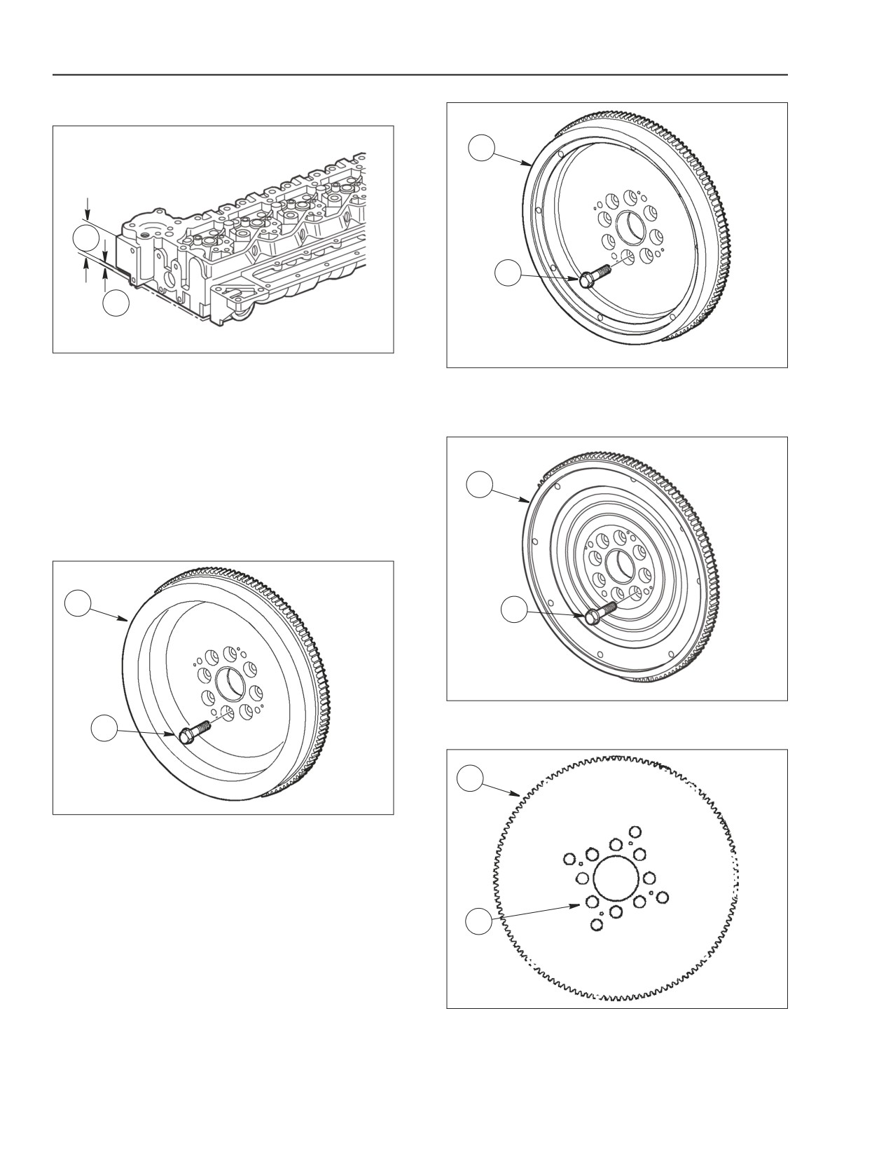
ENGINE HEAD MACHINING
1
A
2
B
BS06K034
Figure 2-28
BS06K037
Figure 2-30
Cylinder head nominal thickness (A) is 105 ±
0.25mm. (4.134 ± 0.0098 in.) and a maximum
ENGINES: 667TA/EED - 667TA/EBD
removal of material (B) must not exceed 0.13mm.
(0.0051 in.).
ENGINE FLYWHEEL
The flywheel (1) is not timed to the crankshaft and
1
does not have any stamping, notch or reference hole
for sensors or timing. Equal position of fastening bolt
holes (2) allows it to be installed in any position.
1
2
BS06K036
Figure 2-31
2
ENGINES: 667TA/EBF - 667TAEED
1
BS06K035
Figure 2-29
ENGINES: 667TA/EEG - 667TA/EEC
2
BS06K629
Figure 2-32
ENGINE: 667TA/EDJ
2-28
Issued 11-06
Bur
87519804 NA
ENGINE REPAIR MANUAL
CHAPTER 2 - 667TA ENGINE OVERHAUL
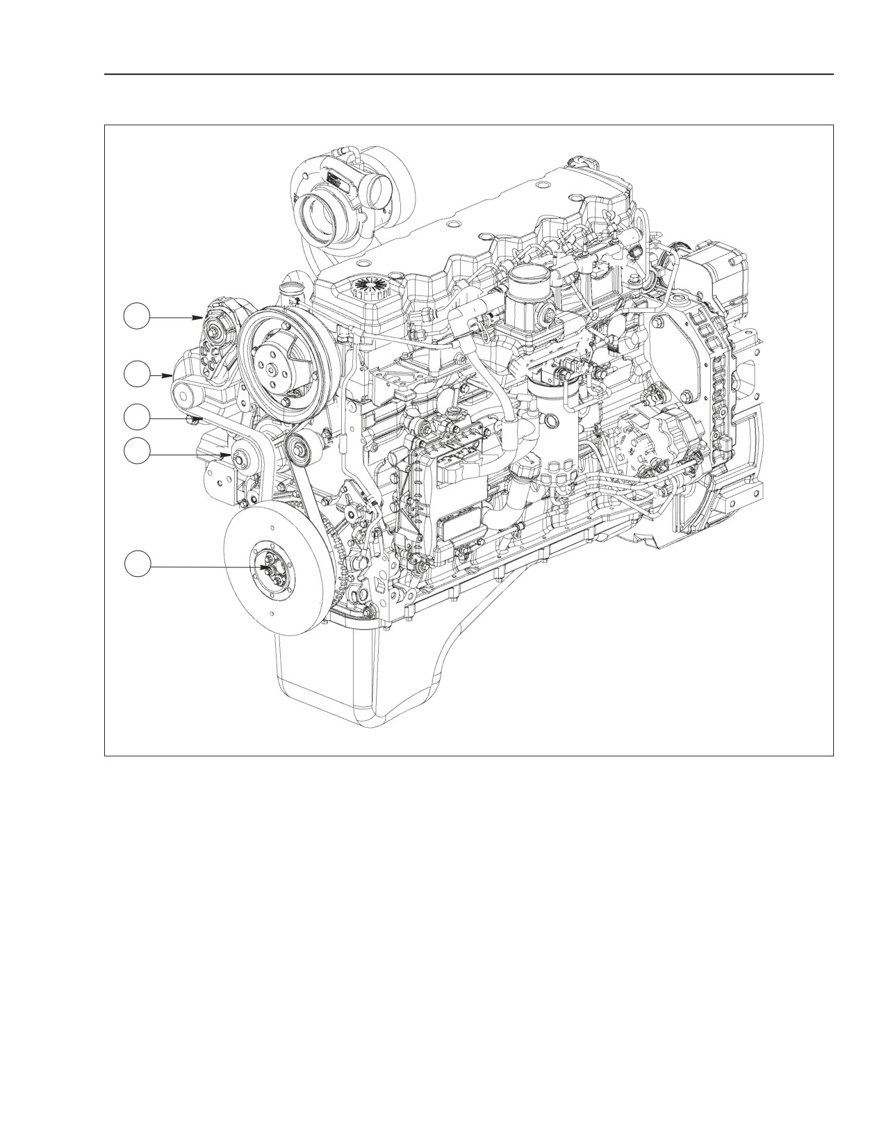
ACCESSORY EQUIPMENT DRIVE
1
2
3
4
5
BS06K038
Figure 2-33
1. AUTOMATIC BELT TENSIONER
2. ALTERNATOR
3. POLY-V-BELT
4. WATER PUMP
5. CRANKSHAFT
A Poly-V-belt (3) transmits the rotation of the
crankshaft (5) to water pump (4) and to the alternator
(2). The tension of the belt is controlled by the
automatic belt tensioner (1).
87519804 NA
Issued 11-06
Bur
2-29
ENGINE REPAIR MANUAL
CHAPTER 2 - 667TA ENGINE OVERHAUL
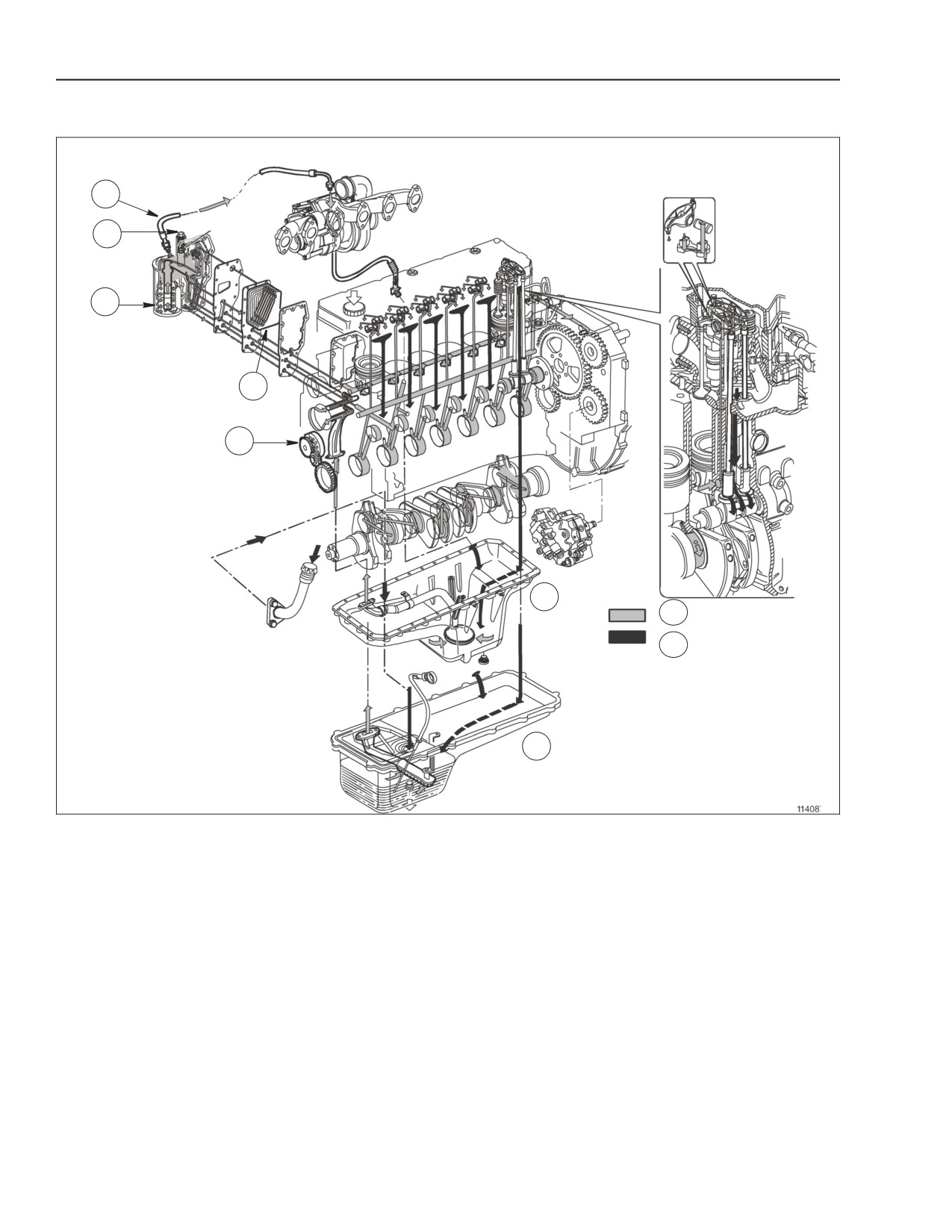
ENGINE LUBRICATION
1
2
3
4
5
A
C
D
B
BS06K039
Figure 2-34
1. TURBO OIL PRESSURE CONTROL VALVE
3. CARTRIDGE -TYPE OIL FILTER
5. OIL PUMP
2. BY-PASS VALVE
4. OIL / WATER COOLER
A. OIL PAN: 667TA/EED - 667TA/EBD
C. PRESSURIZED OIL PATH
B. OIL PAN:667TA/EEG -667TA/EEC -667TA/EBF - 667TA/EED - 667TA/EDJ
D. GRAVITY OIL RETURN PATH
Pressurized lubrication is with the following
components: Gerotor oil pump (5) housed in the front
of the engine block, driven by the spur tooth gear
force fitted on the crankshaft; water / oil cooler (4),
housed in the engine block, under the oil filter
support; by-pass valve (2) for clogged oil filter cut-off,
cartridge- type oil filter (3)
2-30
Issued 11-06
Bur
87519804 NA
ENGINE REPAIR MANUAL
CHAPTER 2 - 667TA ENGINE OVERHAUL
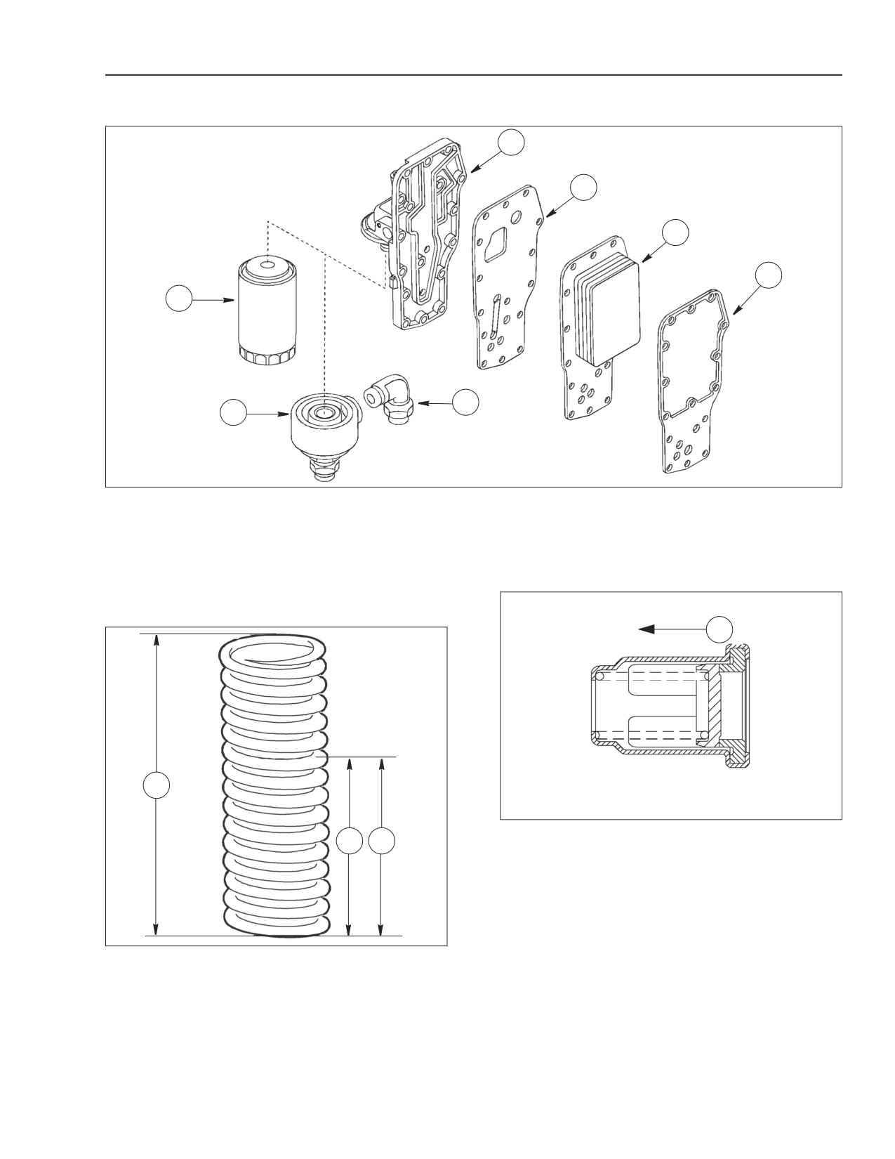
OIL COOLER
1
2
3
4
7
5
6
BS06K040
Figure 2-35
1. HEAT EXCHANGER BODY 3. WATER / OIL COOLER
5. OIL RETURN TO FILTER*
7. OIL FILTER
2. INNER GASKET
4. GASKET (BETWEEN COOLER AND ENGINE BLOCK) 6. OIL FLOW FROM FILTER*
* Only engines: 667TA/EEG - 667TA/EEC.
BY-PASS VALVE
OIL PRESSURE CONTROL VALVE
A
1
BS06K042
Figure 2-37
2
3
A. DIRECTION OF FLOW
Blow-by-max:
20cm³/min (.68oz/min) with 0.83 bar (12 psi)
pressure at 26.7° C (80° F) oil temperature.
BS06K041
Figure 2-36
1. 66MM (2.589 IN)
2. 41.25MM (1.624 IN)
3. 136.9 ± 10.5 N (30.8 ± 2.36 LBF)
Calibration at 100°C (212°F) oil temperature.
- minimum pressure 1.2 bar (17.4 psi).
- maximum pressure 3.8 bar (55.1 psi).
87519804 NA
Issued 11-06
Bur
2-31
ENGINE REPAIR MANUAL
CHAPTER 2 - 667TA ENGINE OVERHAUL
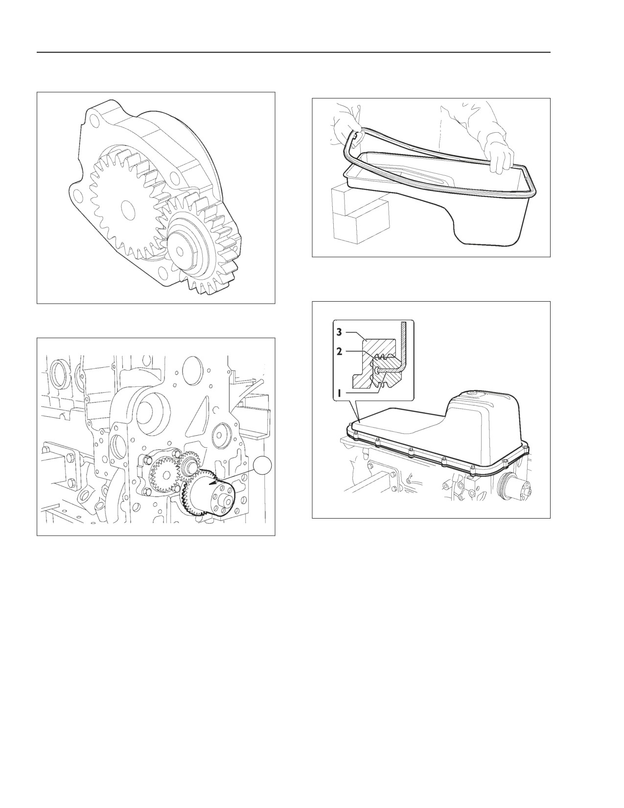
OIL PUMP
OIL PAN (SUMP) ENGINES: 667TA/EEG-
667TA/EEC- 667TA/EBF- 667TA/EED- 667TA/EDJ
BS06K045
Figure 2-40
OIL PAN GASKET INSTALLATION
BS06K043
Figure 2-38
OIL PUMP
1
BS06K046
Figure 2-41
BS06K044
STEEL OIL PAN (SUMP)
Figure 2-39
1.-Crankshaft with oil pump drive gear
CROSS SECTIONAL VIEW OF OIL PAN GASKET
The steel oil pan (sump) (1) is secured to the engine
block by an aluminium plate (3) and a rubber gasket
(2). See figure 2-41.
The C-section rubber gasket (2), installed on the
edge of the oil pan, enhances sealing properties and
also reduces noise levels.
2-32
Issued 11-06
Bur
87519804 NA
ENGINE REPAIR MANUAL
CHAPTER 2 - 667TA ENGINE OVERHAUL
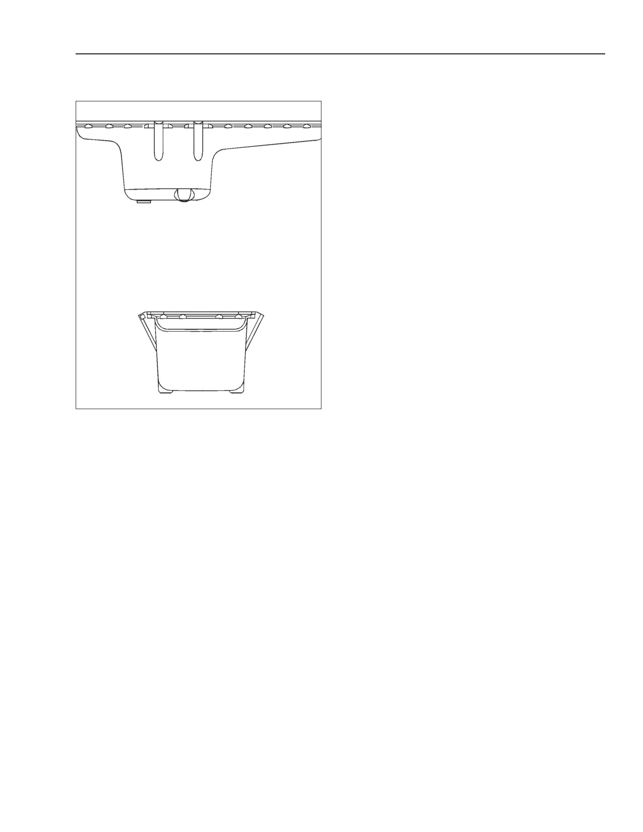
OIL PAN (SUMP) ENGINES: 667TA/EED-
667TA/EBD
BS06K047
Figure 2-42
CAST IRON OIL PAN (SUMP)
The cast iron oil pan (sump) is fastened to the engine
block by bolts with interposed flat washers and a thin
gasket.
87519804 NA
Issued 11-06
Bur
2-33
ENGINE REPAIR MANUAL
CHAPTER 2 - 667TA ENGINE OVERHAUL
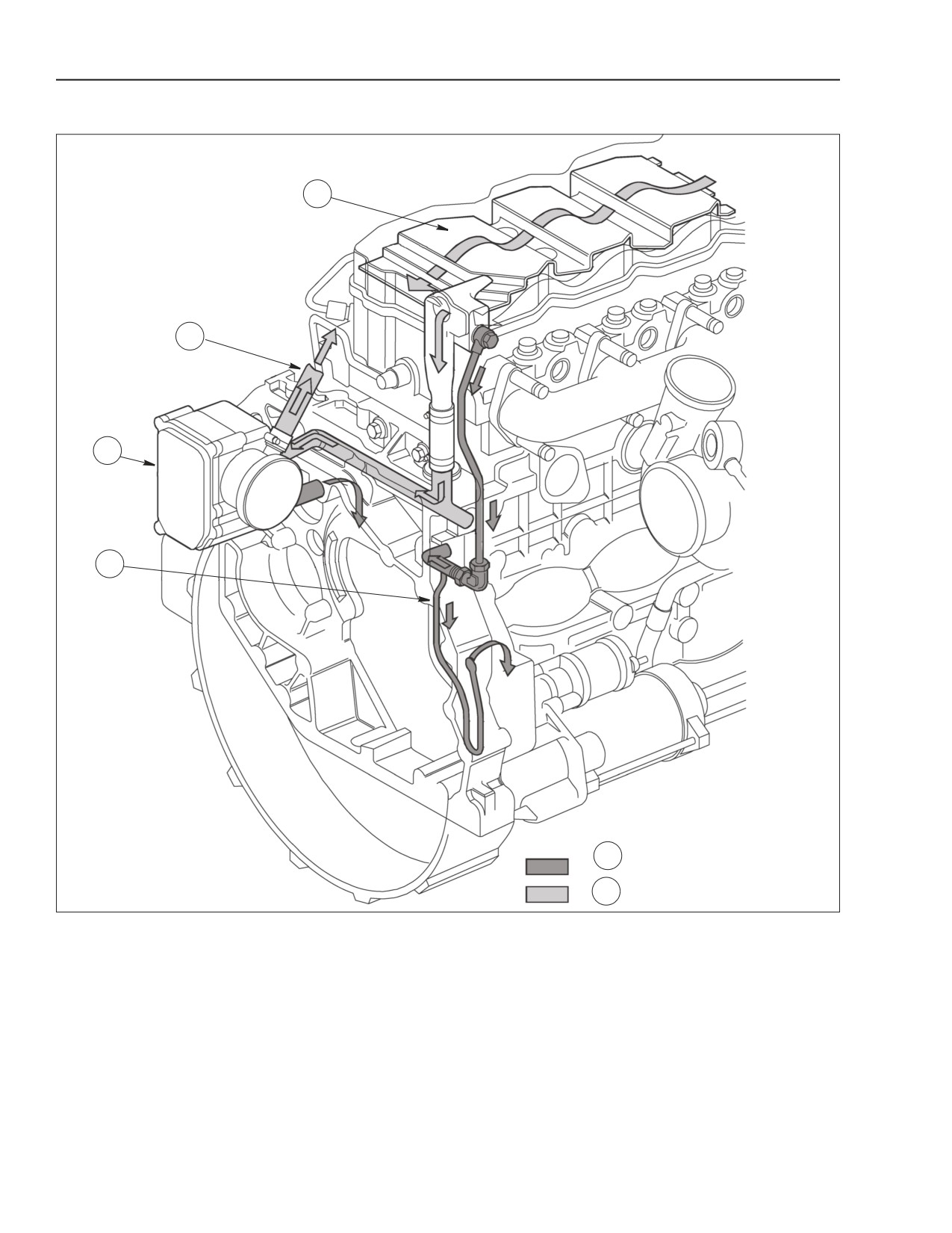
ENGINE OIL VAPOR RECIRCULATION
1
2
3
4
A
B
BS06K048
Figure 2-43
1. PRE-SEPARATOR
3. BLOW-BY FILTER
A. OIL CONDENSATE
2. RECIRCULATION TO INTAKE
4. RETURN TO ENGINE
B. OIL VAPORS
BLOW-BY RECIRCULATION
In blow-by filter (3) a portion of the vapors partially
condense and return to the oil pan (sump) through
The rocker cover has a blow-by pre-separator (1),
line (4), while the remaining is recirculated to the
designed to increase the outlet velocity of blow-by oil
engine intake, by line (2).
vapor while condensing them partially. Condensed
oil returns to the oil pan (sump) while residual vapors
are collected and routed through the blow-by filter
(3).
2-34
Issued 11-06
Bur
87519804 NA
ENGINE REPAIR MANUAL
CHAPTER 2 - 667TA ENGINE OVERHAUL
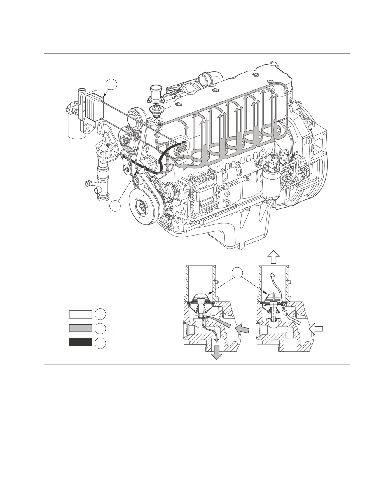
ENGINE COOLING
1
2
3
A
B
C
BS06K049
Figure 2-44
1. OIL COOLER
3. THERMOSTAT
B. WATER RECIRCULATING IN ENGINE
2. WATER PUMP
A. WATER FROM THERMOSTAT OUTLET
C. WATER TO PUMP INLET
• Thermostat, used to regulate coolant flow.
The engine cooling system is a closed circuit
circulation type and is made up of the following
components:
• Oil cooler used to cool the lubricating oil, see oil
cooler page 2-31.
• Centrifugal water pump, housed in the front of the
engine block.
87519804 NA
Issued 11-06
Bur
2-35
ENGINE REPAIR MANUAL
CHAPTER 2 - 667TA ENGINE OVERHAUL
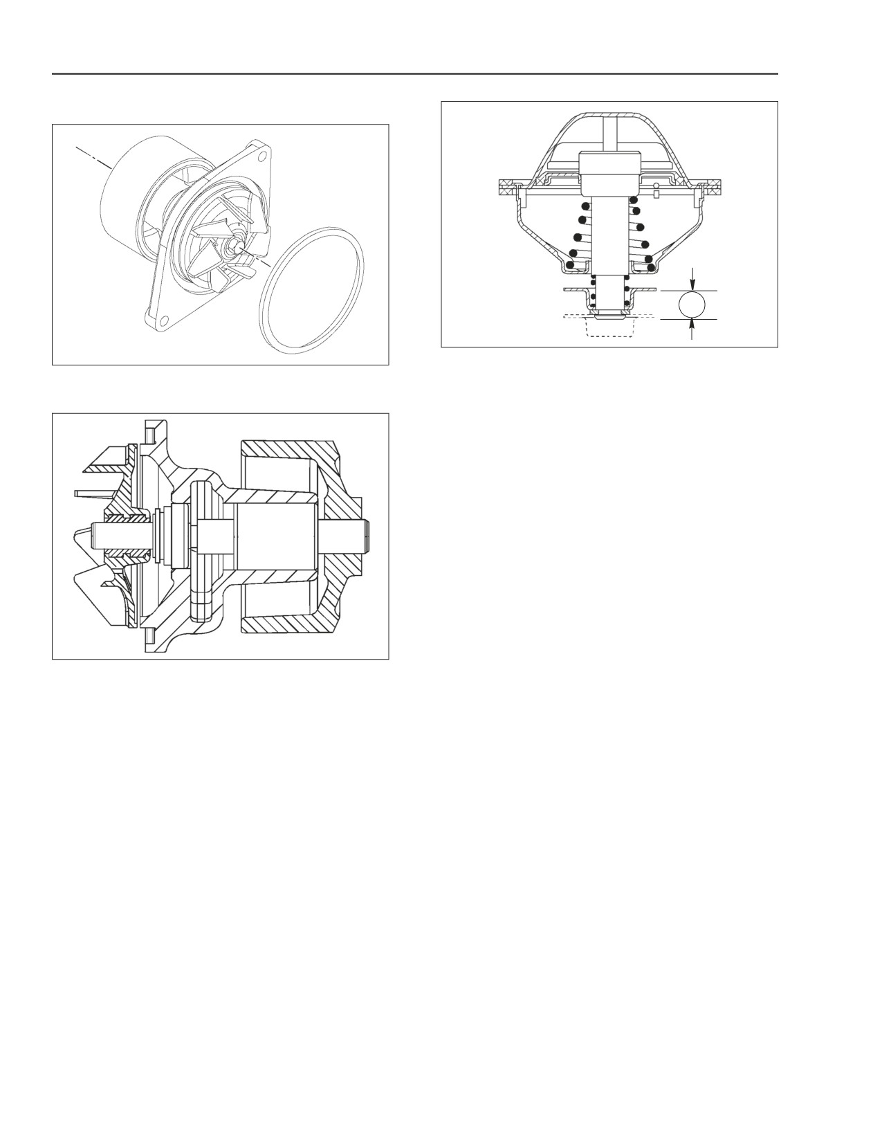
WATER PUMP
A
BS06K052
Figure 2-47
BS06K050
Figure 2-45
THERMOSTAT
WATER PUMP
A. STROKE STARTS AT 96° C (204° F) ≥ 7.5MM (.30 IN).
Thermostat opening for engines:
667TA/EEG, EEC, EBF, EED, EBD= 79 to 83° C
(174 to 181° F).
667TA/EDJ= 83 to 98° C (181 to 208° F).
BS06K051
Figure 2-46
WATER PUMP CROSS SECTION
The water pump is housed in a cavity in the front of
the engine block, and is driven by a Poly-V belt. The
water pump is sealed to the block by a rubber ring.
The engine temperature is controlled by a
thermostat.
2-36
Issued 11-06
Bur
87519804 NA

ENGINE REPAIR MANUAL
CHAPTER 2 - 667TA ENGINE OVERHAUL
HIGH PRESSURE ELECTRONIC INJECTION SYSTEM (COMMON RAIL)
1
2
3
11
10
9
4
8
7
6
5
BS06K053
Figure 2-48
1. HARNESS TO INJECTORS
5. CRANKSHAFT SENSOR
9. CAMSHAFT SENSOR
2. ELECTRO- INJECTOR
6. EDC7UC31 CONTROL UNIT
10. FUEL PRESSURE SENSOR
3. COOLANT TEMP. SENSOR
7. PRESSURE REGULATOR
11. BOOST TEMP. PRESSURE SENSOR
4. ENGINE OIL AND PRESSURE SENSOR
8. FUEL HEATER AND TEMP. SENSOR
Extremely high injection pressures are necessary in
order to reduce PARTICULAR emissions.
The common rail system makes it possible to inject
fuel at pressures of up to 1450 - 1600 bar (21030 -
23206 psi), while the injection precision obtained by
EDC7UC31 electronic control of the system serves
to optimize operation of the engine while limiting
emissions and fuel consumption.
For engines more powerful than 152 kW (203 hp.),
the CRIN2 injectors have DLLA nozzles that work up
to a pressure of 1600 bar (23206 psi), while engines
less powerful than 152 kW (203 hp.) are fitted with
DSLA nozzles which work with pressures up to 1450
bar (21030 psi.)
87519804 NA
Issued 11-06
Bur
2-37
ENGINE REPAIR MANUAL
CHAPTER 2 - 667TA ENGINE OVERHAUL
EDC7UC31 -ELECTRONIC CONTROL
MAXIMUM ENGINE SPEED LIMITING
UNIT OPERATION
Depending on the application, the control unit
memory can contain appropriate engine speed limits.
ENGINE PREHEATING ELEMENT CONTROL
When the engine speed surpasses these limits, the
Pre-post heating is activated when even just one of
control unit activates power reduction by controlling
the water, air or fuel temperature sensors detects a
turn on time of the electro-injectors. In some
temperature of less than 5° C (41° F).
applications, the maximum limiting response consists
in stopping the engine.
PHASE RECOGNITION
CUT OFF
Signals transmitted by the camshaft and crankshaft
sensors determine the cylinder which fuel must be
Fuel cut-off release is managed by the control unit
injected.
with the following logical interventions:
• deactivation of the electro-injectors.
INJECTION CONTROL
• reactivation of electro-injectors immediately prior
Information transmitted by the sensors, the control
to arrival at idle speed.
unit determines and regulates pressure and modifies
• control of fuel pressure regulator.
the pre-injection and main injection mode.
SMOKE CONTROL UNDER ACCELERATION
INJECTION PRESSURE CLOSED LOOP
CONTROL
With intense load demands, signals received from
the boost temperature pressure sensor and the
Engine load, determined by processing of data
crankshaft sensor, the control unit manages the
transmitted by the various sensors, and the control
pressure regulator and modulates the activation time
unit. Governs the regulator to maintain injection
of the electro-injectors to prevent the emission of
pressure at constant optimal values.
smoke from the exhaust.
PILOT AND MAIN INJECTION ADVANCE
CONTROL
AFTER ENGINE SHUT DOWN
Signals transmitted by various sensors to the control
After the engine is stopped, the control unit
unit, determines the optimum injection point on the
microprocessor saves various parameters to the
basis of internal mapping.
EEPROM memory, including the fault log so that they
will be available the next time the engine is started.
IDLE SPEED CONTROL
CONTROL OF WORKING SPEED IN NORMAL
The control unit processes signals transmitted by the
OPERATING CONDITIONS
various sensors and adjusts the quantity of fuel
Each time work load varies, the control unit adjusts
injected.
torque to maintain the engine in maximum power
It also controls the pressure regulator and modulates
conditions. If the load causes a reduction in power,
injection duration of the electro-injectors. Within
the control unit increases torque i.e. it increases the
specific limits, the control unit also monitors battery
amount of fuel injected in order to restore the engine
voltage.
to maximum power.
OVERHEATING PROTECTION
If the water temperature reaches 110° C (230° F) the
control unit reduces engine performance.
When the temperature returns below 100° C (212° F)
the engine resumes normal operation. In some
applications, the intake manifold temperature is the
reference temperature.
2-38
Issued 11-06
Bur
87519804 NA
ENGINE REPAIR MANUAL
CHAPTER 2 - 667TA ENGINE OVERHAUL
RECOVER STRATEGIES
• Control of fuel leaks.
In the case of fuel supply problems, the system
controls the engine with suitable constant power
values obtained with a low number of rev and high
torque values in order to inject the maximum quantity
of fuel.
• Control of pressure in the rail.
When the pressure in the rail exceeds safety values,
the engine reduces power.
• Synchronism problems
In the case of synchronism problems, faulty rev
sensors, the system controls the engine by
increasing the number of revs in order to improve
interpretation of the signals.
• Power restrictions as operating temperature
increases.
When the temperature of the supercharging air rises
above 88° C (190° F), power reduction is started,
when a temperature of 120° C (248° F) is reached,
performance is further reduced and is comparable to
that of the same engine if it were aspirated.
• Reduction of power as reference temperature
varies
In normal operating conditions, the system knows the
supercharging air, oil and water temperatures.
If the temperature of the engine water is not
available, the system takes the temperature of the oil
as reference and when this reaches the threshold of
103° C (217° F), it starts to reduce the power
available. On reaching 113° C (235° F), power is
reduced to 50%.
87519804 NA
Issued 11-06
Bur
2-39
ENGINE REPAIR MANUAL
CHAPTER 2 - 667TA ENGINE OVERHAUL
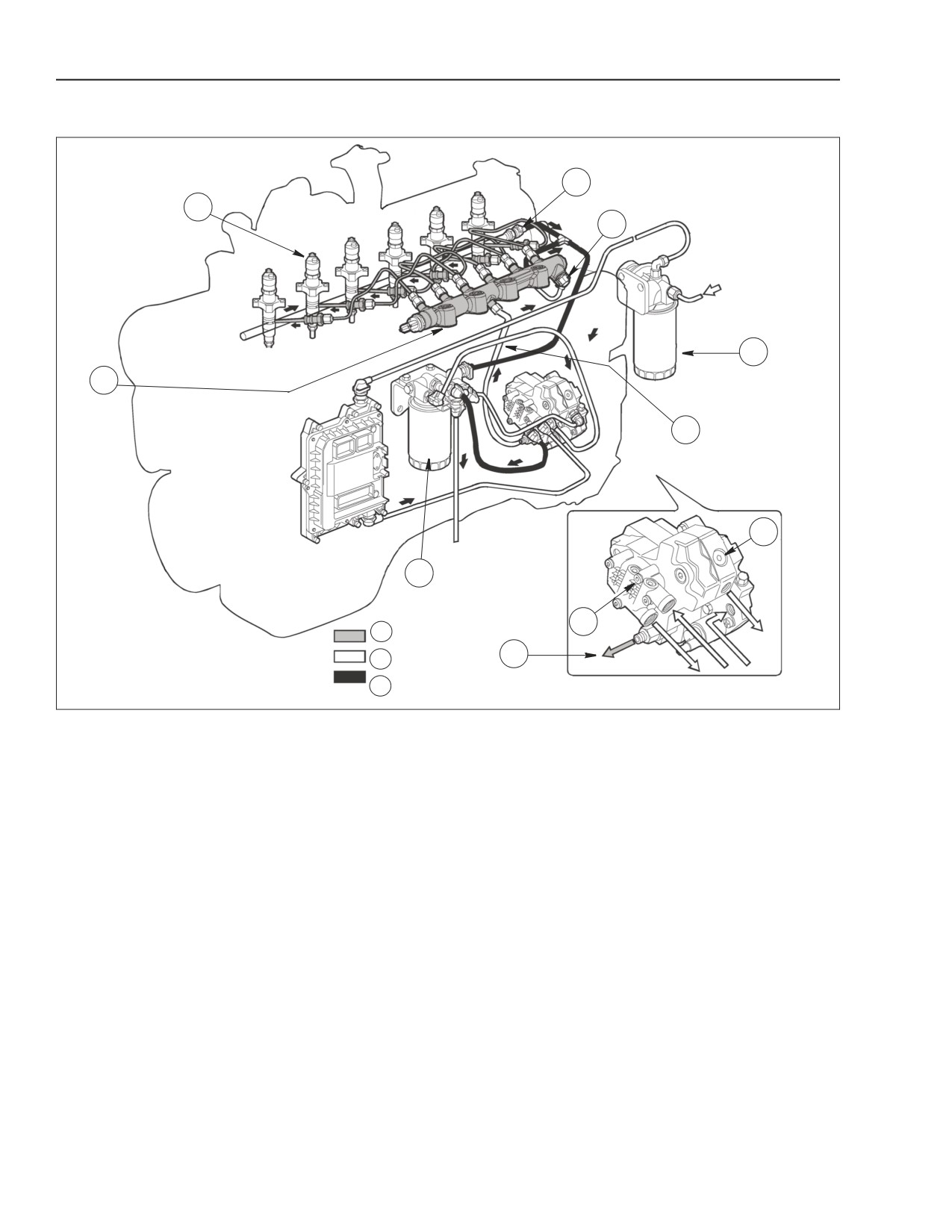
FUEL SUPPLY SYSTEM
6
1
5
4
2
D
8
3
7
A
D
B
C
BS06K054
Figure 2-49
7. LOW PRESSURE GEAR TYPE
1. ELECTRO-INJECTOR 4. PRE-FILTER
B. LOW PRESSURE
CHARGE PUMP
5. COMMON RAIL PRESSURE RELIEF
2. COMMON RAIL
8. HIGH PRESSURE PUMP
C. FUEL RETURN
VALVE
6. BACK PRESSURE REGULATOR FOR
D. HIGH PRESSURE FROM
3. FUEL FILTER
A. HIGH PRESSURE
FUEL RETURN
PUMP TERMINAL
The common rail system has a high pressure pump
The high pressure circuit consists of the following
that constantly keeps the fuel supply at a very high
lines:
pressure, not dependent on the phase of the cylinder
• Line connecting the high pressure pump outlet to
that must receive the injection. The high pressure
the common rail.
fuel is stored in a pipeline (the common rail) that is
• Lines supplying the electro-injectors from the
shared by all electro- injectors.
common rail.
This means that there is always a supply of fuel
The low pressure circuit is composed of the following
available at the electro- injector inlet at the injection
lines:
pressure determined by the EDC7UC31 electronic
control unit.
• Fuel line from fuel tank to prefilter.
When the solenoid valve of an electro- injector is
• Lines supplying the mechanical supply pump
energized by the EDC7UC31 electronic control unit,
through the heat exchanger of the control unit, the
fuel taken directly from the common rail is injected
manual priming pump and the pre filter.
into the corresponding cylinder.
The fuel system is completed by the fuel return from
The fuel system is composed of a low pressure
the common rail, injectors and high pressure pump
circuit and a high pressure circuit.
cooling circuit.
2-40
Issued 11-06
Bur
87519804 NA
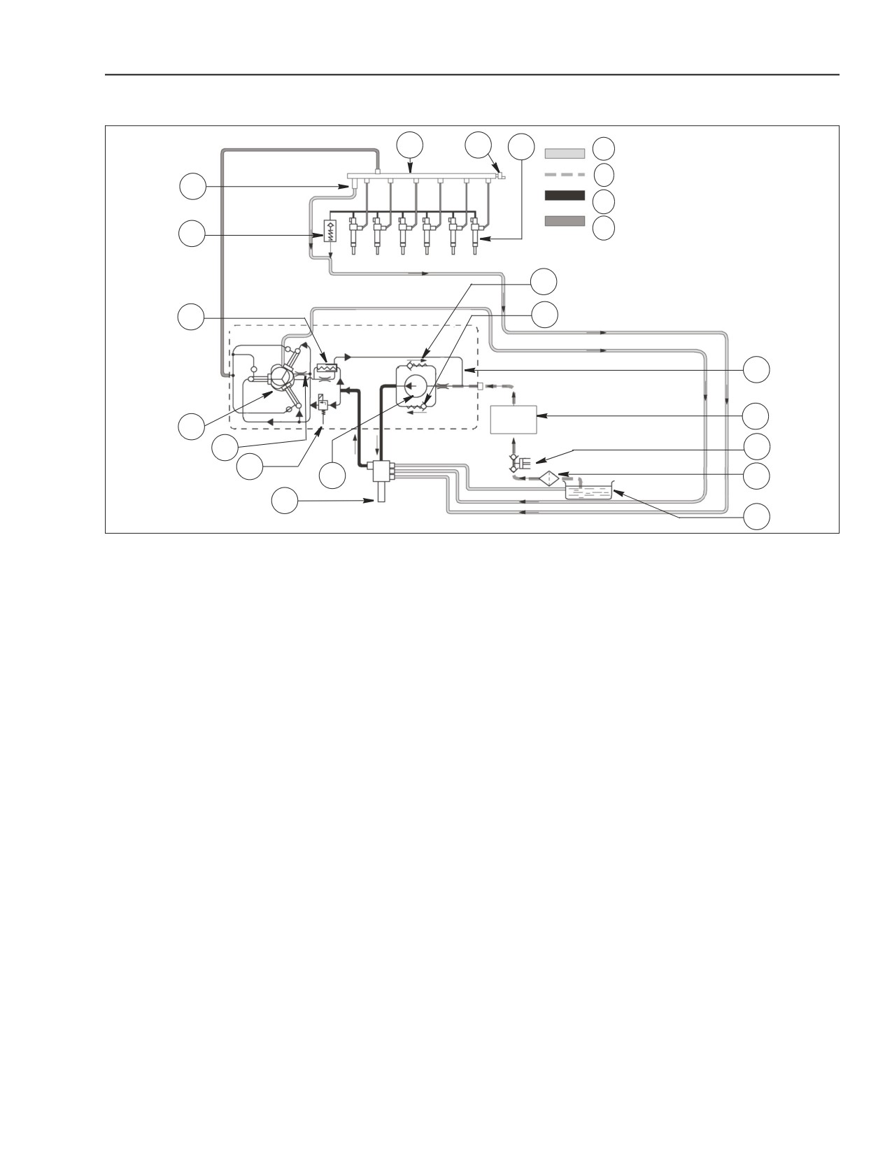
ENGINE REPAIR MANUAL
CHAPTER 2 - 667TA ENGINE OVERHAUL
FUEL SUPPLY SYSTEM DIAGRAM
5
6
7
A
B
4
C
D
3
18
2
17
8
9
1
16
10
15
13
11
14
12
BS06K055
Figure 2-50
17.
MECHANICAL ROTOR PUMP
1. HIGH PRESSURE PUMP
9.
EDC7UC31 CONTROL UNIT HEAT EXCHANGER
BY-PASS CHECK VALVE
2. LOW PRESSURE REGULATOR VALVE
18.
ROTOR PUMP PRESSURE
10.
MANUAL PRIMING PUMP
ON HIGH PRESSURE PUMP
SAFETY BY-PASS
3. COMMON RAIL SAFETY RELIEF VALVE
11.
PRE-FILTER
A.
DRAIN
4. BACK PRESSURE VALVE IN FUEL
12.
FUEL TANK
B.
SUCTION
RETURN LINE FROM INJECTOR
5. COMMON RAIL
13.
GEAR CHARGE FEED PUMP
C. LOW PRESSURE
6. RAIL PRESSURE SENSOR
14.
FUEL FILTER
D. HIGH PRESSURE
7. ELECTRO-INJECTOR
15.
HIGH PRESSURE PUMP BY-PASS CHECK VALVE
8. HIGH PRESSURE PUMP AND INJECTOR
16.
RETURN LINE FROM HIGH PRESSURE PUMP
RETURN LINE
The supply pressure regulator controls the flow of
In parallel with the mechanical supply pump there are
fuel needed in the low pressure system. The high
two by-pass valves.
pressure pump supplies the common rail. This
Rotor pump pressure safety by-pass valve (18)
pressurization of fuel, improves energy efficiency and
makes it possible to have the fuel flow back from the
limits the heating of the fuel in the system.
mechanical pump outlet to its inlet, when the
The low pressure regulator valve (2) installed on the
pressure at the fuel filter inlet exceeds the
high pressure pump maintains the pressure at a
permissible limit. The rotor pump by-pass valve (17)
constant level of 5 bars (72 psi.).
makes it possible to fill the supply system via the
manual priming pump (10).
Low pressure regulator valve (2) operates to
increase fuel flow in the high pressure pump cooling
circuit through line (16) carrying fluid into and out of
line (8).
The common rail safety relief valve (3) installed in the
cylinder head. Controls the flow of fuel returning from
the electro-injectors at a pressure of 1.3 to 2 bars (19
to 29 psi.).
87519804 NA
Issued 11-06
Bur
2-41
ENGINE REPAIR MANUAL
CHAPTER 2 - 667TA ENGINE OVERHAUL
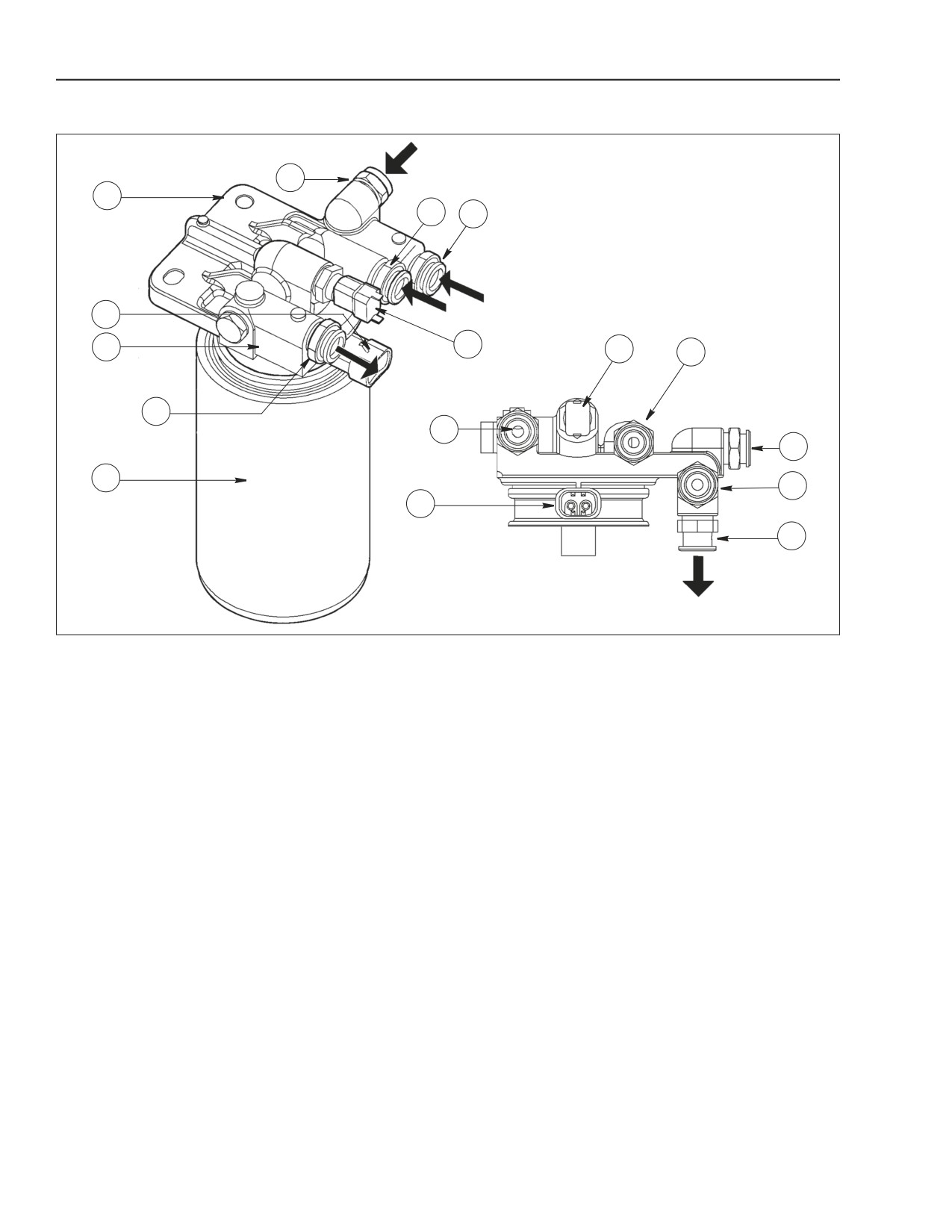
FUEL FILTER
B
1
D C
2
3
5
5
D
A
A
B
4
C
2
E
BS06K056
Figure 2-51
1. FUEL FILTER BRACKET
A. OUTLET CONNECTION TO HIGH PRESSURE PUMP
2. FUEL HEATER CONNECTOR
B. COMMON RAIL, CYLINDER HEAD INJECTORS DISCHARGE LINE INLET CONNECTION
3. ELECTRIC FUEL HEATER
C. CONNECTION TO HIGH PRESSURE PUMP DISCHARGE LINE
4. FUEL FILTER
D. INLET CONNECTION FROM FEED PUMP
5. FUEL TEMPERATURE SENSOR E. OUTLET CONNECTION TO FUEL TANK
The fuel filter is installed on the engine cylinder block
The heater is activated if the fuel temperature is less
in the circuit between supply pump and high pressure
than 0° C (32° F) and is heated until the fuel reaches
pump (CP3).
5° C (41° F). Fuel temperature is monitored by the
EDC7UC31 control unit.
2-42
Issued 11-06
Bur
87519804 NA
ENGINE REPAIR MANUAL
CHAPTER 2 - 667TA ENGINE OVERHAUL
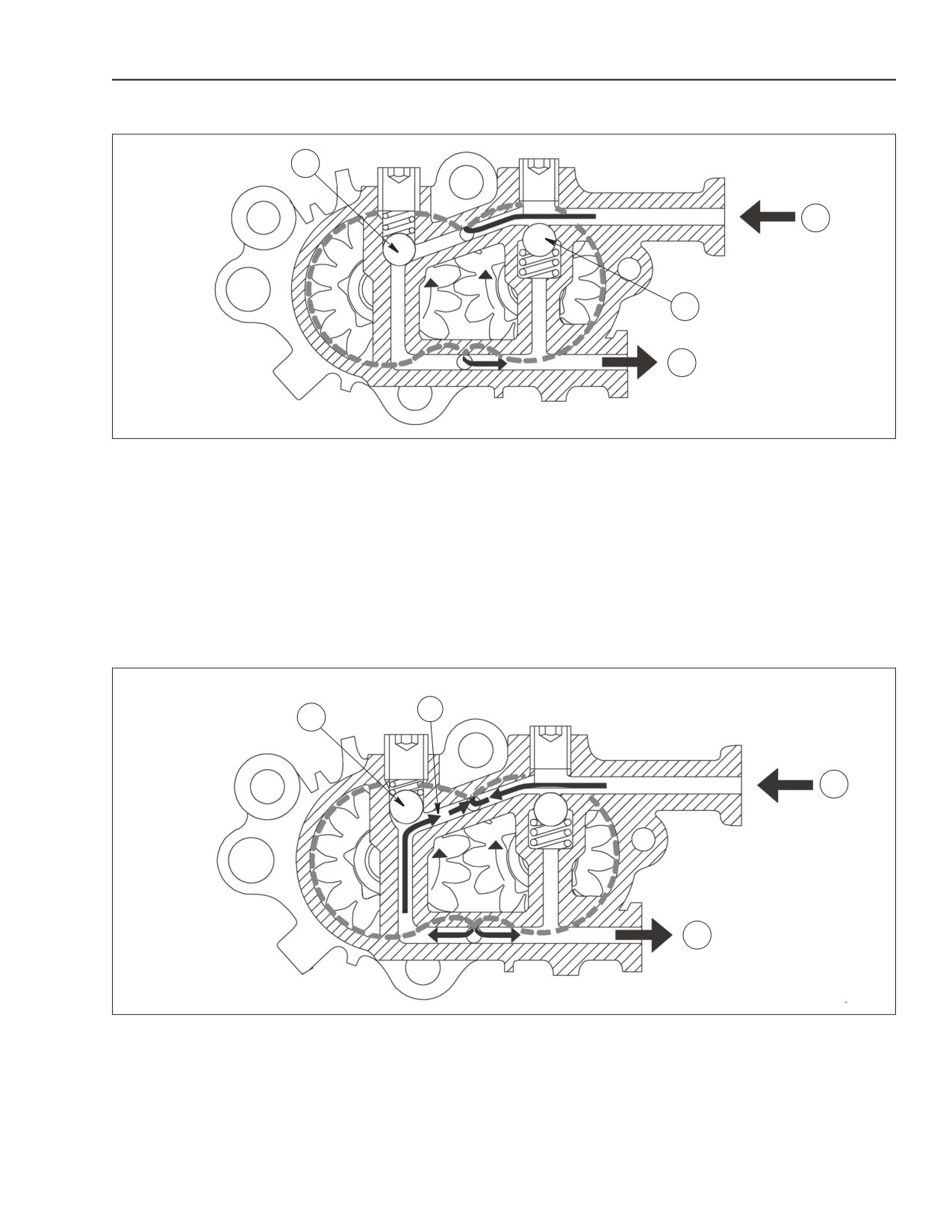
MECHANICAL SUPPLY PUMP- NORMAL OPERATING CONDITION
1
A
2
B
BS06K057
Figure 2-52
1. PRESSURE SAFETY VALVE
A. FUEL INLET FROM TANK
2. PRIMING BY-PASS VALVE IN CLOSED POSITION
B. FUEL OUTLET TO FILTER
The charge gear pump, installed on the rear of the
The feed pump is driven by the high pressure pump
high pressure pump, draws fuel from the tank
shaft.
through the pre-filter and sends it through the main
In normal operating conditions the flow in the feed
fuel filter to the high pressure pump.
pump enters port (A), flows around the outside of the
gears and out through port (B).
MECHANICAL SUPPLY PUMP- OUTLET OVERPRESSURE CONDITION
2
1
A
B
BS06K058
Figure 2-53
1. PRESSURE SAFETY VALVE A. FUEL INLET FROM TANK
2. BY-PASS PORT
B. FUEL OUTLET TO FILTER
Pressure safety valve (1) opens when pump outlet
spring (1) allowing fuel to flow to the pump inlet
pressure (B), is excessive due to filter restriction or
through passage (2).
charge pressure regulator malfunction. The pressure
of the fuel would then overcome the force exerted by
87519804 NA
Issued 11-06
Bur
2-43
ENGINE REPAIR MANUAL
CHAPTER 2 - 667TA ENGINE OVERHAUL
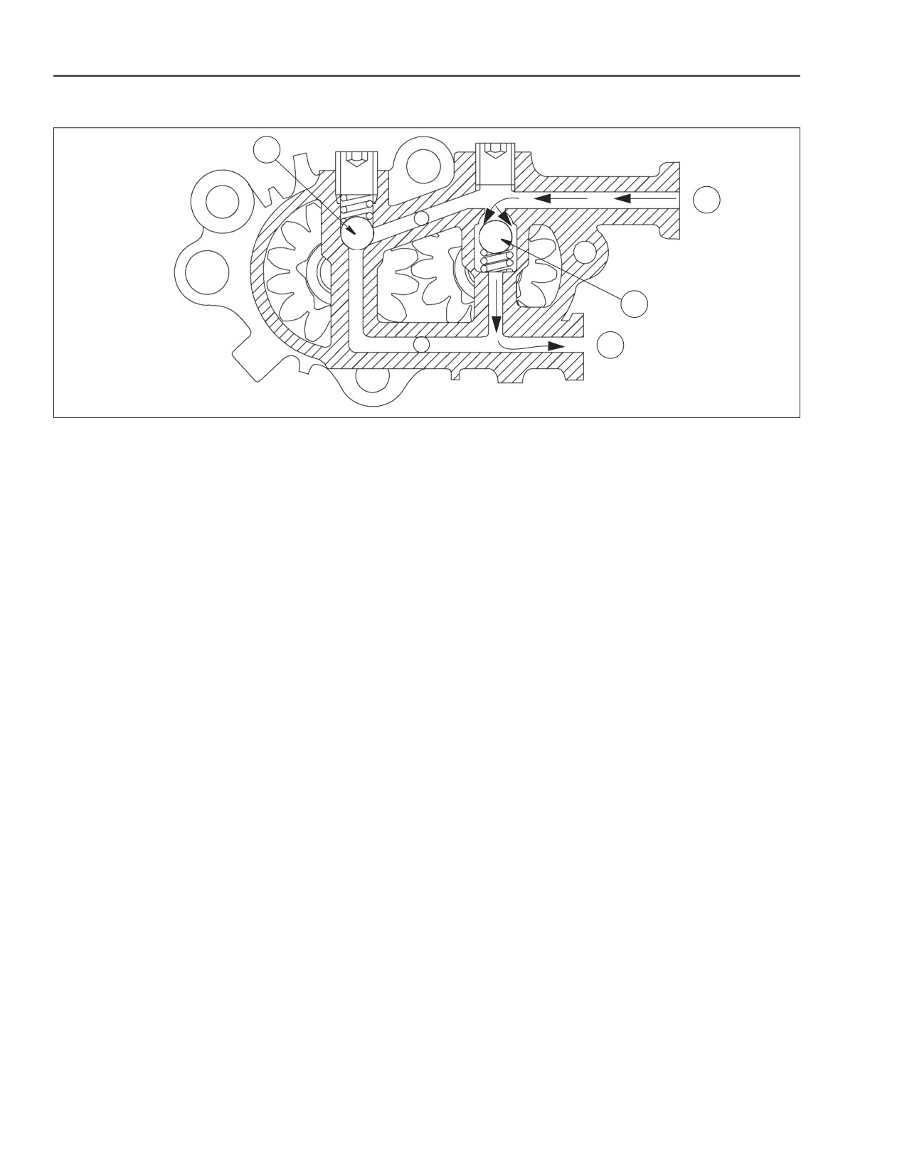
FUEL SYSTEM BLEEDING
1
A
2
B
BS06K059
Figure 2-54
1. PRESSURE SAFETY VALVE
A. FUEL INLET FROM TANK
2. PRIMING BY-PASS VALVE IN CLOSED POSITION
B. FUEL OUTLET TO FILTER
The by-pass valve (2) opens when, the engine is
When activating the hand pump the by-pass valve (2)
turned off. The supply system has to be filled with the
is opened due to inlet pressure, this allows the fuel
manual priming pump.
flow to outlet (B).
2-44
Issued 11-06
Bur
87519804 NA
ENGINE REPAIR MANUAL
CHAPTER 2 - 667TA ENGINE OVERHAUL
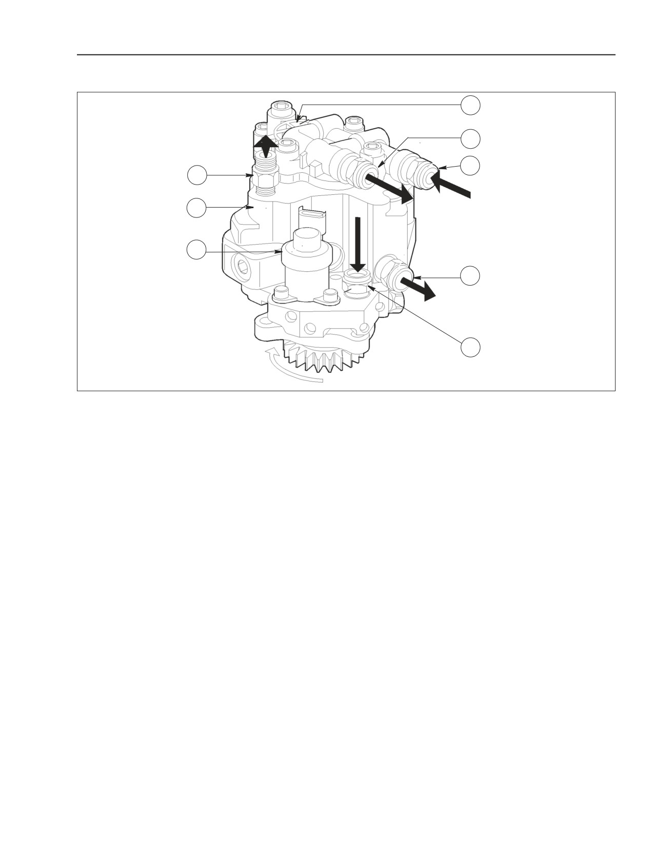
HIGH PRESSURE PUMP TYPE CP3.3
8
7
6
1
2
3
5
4
BS06K060
Figure 2-55
HIGH PRESSURE PUMP
1. FUEL OUTLET CONNECTION TO RAIL
2. HIGH PRESSURE PUMP
3. HIGH PRESSURE REGULATOR
4. FUEL INLET CONNECTION FROM FILTER
5. FUEL DRAIN RETURN CONNECTION TO FILTER BRACKET
6. FUEL INLET CONNECTION FROM CONTROL UNIT HEAT EXCHANGER
7. FUEL OUTLET CONNECTION FROM MECHANICAL PUMP TO FILTER
8. MECHANICAL GEAR CHARGE PUMP
The high pressure pump has 3 radial plungers driven
On the rear of the high pressure pump is the
by the cam gear. The pump does not need to be
mechanical gear feed pump which is driven by the
timed.
high pressure pump shaft.
IMPORTANT: The high pressure pump unit can not be overhauled, there are no adjustments.
87519804 NA
Issued 11-06
Bur
2-45
ENGINE REPAIR MANUAL
CHAPTER 2 - 667TA ENGINE OVERHAUL
5
1
6
2
7
8
3
4
9
BS06K061
Figure 2-56
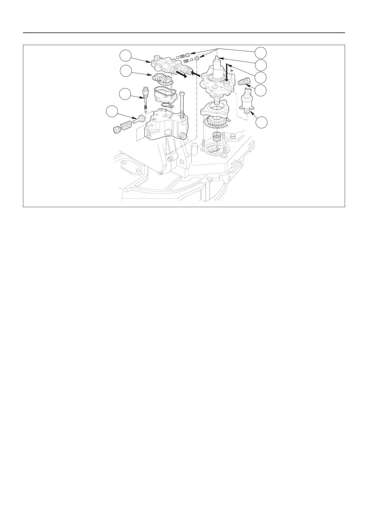
EXPLODED VIEW OF HIGH PRESSURE PUMP
4. INDIVIDUAL HIGH PRESSURE PUMP
7. HIGH PRESSURE PUMP FUEL
1. MECHANICAL GEAR CHARGE FEED PUMP
PLUNGER (1 OF 3)
INLET FROM FILTER
8. 5 BAR (72 PSI) LOW PRESSURE
2. GEAR SET
5. BY-PASS VALVES ON FEED PUMP
FUEL REGULATOR VALVE
3. HIGH PRESSURE FUEL DELIVERY VALVE TO
9. HIGH PRESSURE REGULATOR
6. PUMP SHAFT
COMMON RAIL
SOLENOID VALVE
2-46
Issued 11-06
Bur
87519804 NA
ENGINE REPAIR MANUAL
CHAPTER 2 - 667TA ENGINE OVERHAUL
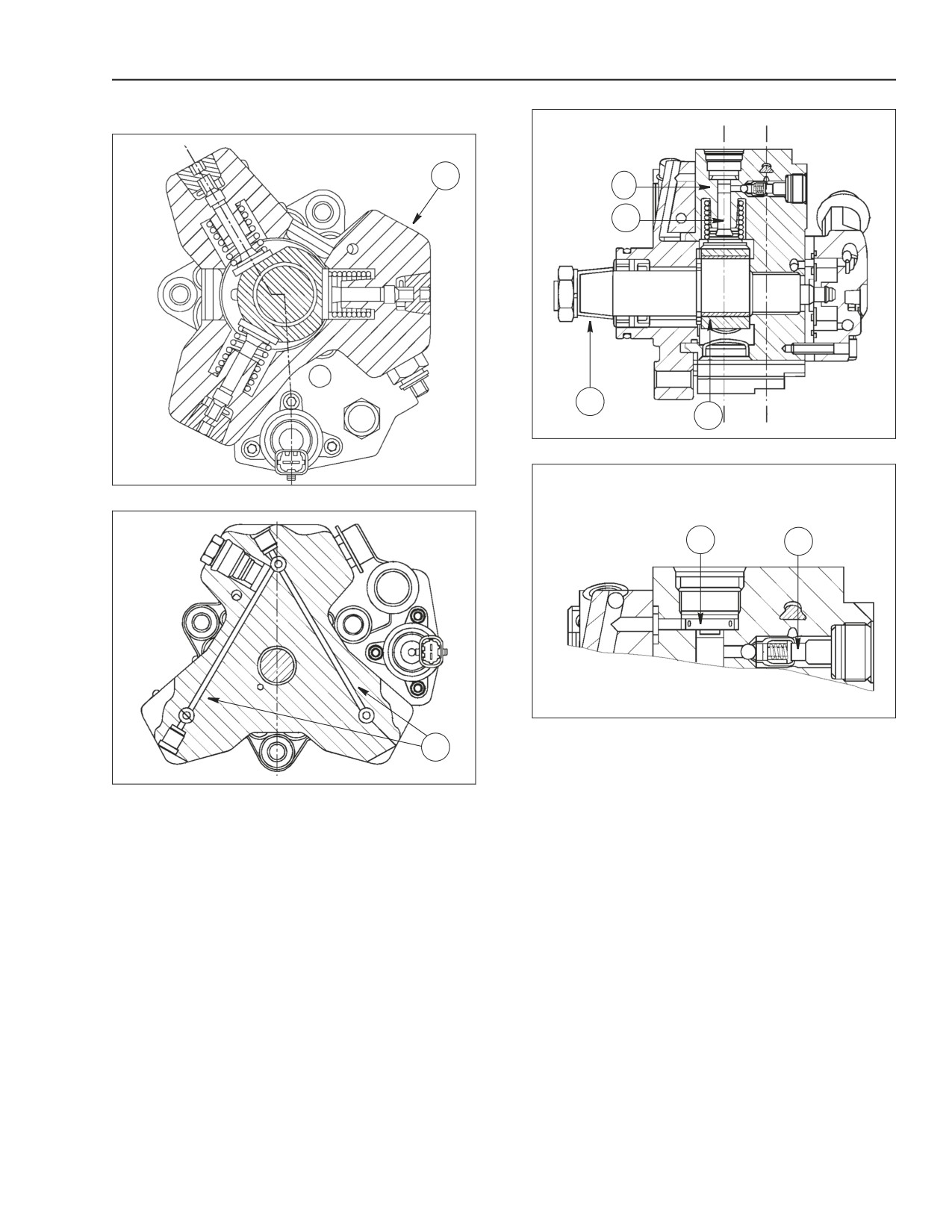
HIGH PRESSURE PUMP INSIDE STRUCTURE
7
1
5
6
2
BS06K161
Figure 2-59
BS06K160
Figure 2-57
3
4
BS06K159
Figure 2-60
8
BS06K158
Figure 2-58
1. CYLINDER
5. PISTON
2. THREE LOBE ELEMENT
6. PUMP SHAFT
3. CAP INTAKE VALVE
7. LOW PRESSURE FUEL INLET
4. BALL DELIVERY VALVE
8. PUMPING ELEMENTS SUPPLYING FUEL DUCTS
Pumping unit is composed of:
• Three pistons (5) which are actuated by a three
lobe element (2) on the pump shaft (6) When the
shaft
(6) rotates the three lobe element
(2)
actuates the piston (5) pumping high pressure fuel
past the ball delivery valve (4) to the common rail.
87519804 NA
Issued 11-06
Bur
2-47
ENGINE REPAIR MANUAL
CHAPTER 2 - 667TA ENGINE OVERHAUL
OPERATING PRINCIPAL
1
2
7
3
4
5
6
BS06K063
Figure 2-61
BS06K160
Figure 2-62
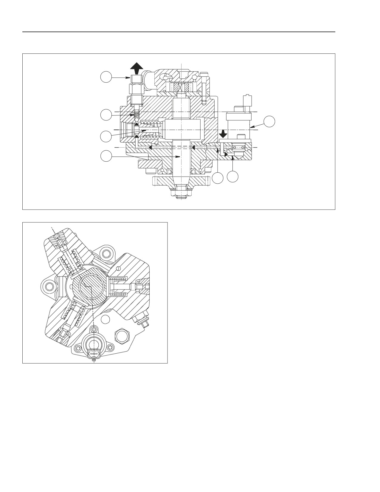
7. HIGH PRESSURE
1. OUTLET FOR RAIL DELIVERY LINE
3. HIGH PRESSURE PLUNGER
5. PLUNGER SUPPLY PASSAGE
REGULATOR
6. PRESSURE REGULATOR
2. RAIL DELIVERY VALVE
4. PUMP SHAFT
SUPPLY PASSAGE
High pressure plunger (3) rides on the cam installed
During the plunger compression phase the fuel
on the pump shaft (4). In the intake phase the
reaches sufficient pressure to open the common rail
plunger is supplied with fuel through the supply
delivery valve (2) and is forced through outlet (1) to
passage (5). The quantity of fuel to supply to the
the common rail.
plunger is determined by pressure regulator (7). The
pressure regulator controls high pressure pump
outlet flow based on PWM (pulse width modulated)
command received from the EDC7UC31 control unit.
2-48
Issued 11-06
Bur
87519804 NA
ENGINE REPAIR MANUAL
CHAPTER 2 - 667TA ENGINE OVERHAUL
3
1
1
6
2
7
3
8
4
2
9
5
BS06K064
BS06K065
Figure 2-64
Figure 2-63
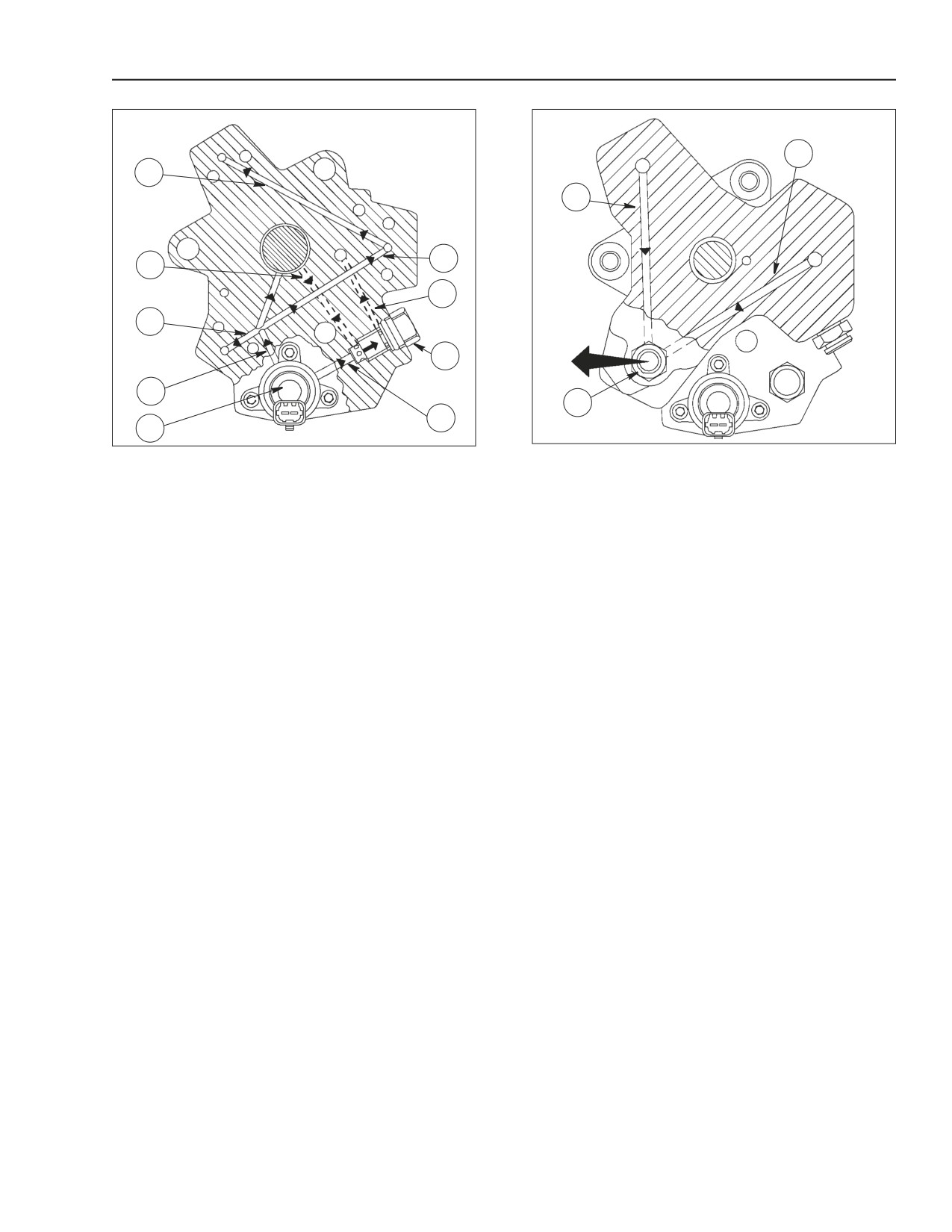
1. INLET TO HIGH PRESSURE PLUNGERS
1. FUEL EXHAUST FLUE
2. PUMP LUBRICATION PASSAGES
2. FUEL EXHAUST FLOWING FROM PUMP WITH
CONNECTOR TO HIGH PRESSURE LINE FOR
3. INLET TO HIGH PRESSURE PLUNGERS
COMMON RAIL
4. MAIN PLUNGERS SUPPLY PASSAGE
3. FUEL EXHAUST GALLERY
5. HIGH PRESSURE REGULATOR VALVE
6. INLET TO HIGH PRESSURE PLUNGERS
The figure above shows the fuel flow under high
7. CHARGE PRESSURE REGULATOR DRAIN PASSAGE
pressure running through the exhaust galleries of the
8. CHARGE PRESSURE 5 BAR (72 PSI) REGULATOR VALVE
pumping elements.
9. FUEL DISCHARGE FROM HIGH PRESSURE REGULATOR
VALVE INLET
THEORY OF OPERATION
The figure above shows the low pressure fuel
The cylinder is filled through the cap intake valve
passages inside the pump. The figure shows the
only if the supply pressure is suitable to open the
main plungers supply passage (4), the individual
delivery valves set on the pumping elements about
plunger supply passages (1, 3, 6), the passages
2 bars (29 psi.).
utilized for lubrication of the pump (2), the high
pressure regulator (5), the 5 bar (72 psi) pressure
The amount of fuel supplying the high pressure pump
regulator valve (8) and the fuel discharge passage
is metered by the high pressure regulator. The high
(7).
pressure regulator is controlled by the EDC7UC31
control unit through a PWM (pulse width modulated)
The high pressure regulator (5) determines the
signal.
quantity of fuel which the high pressure plungers
deliver to the common rail. Excess fuel flows out
When fuel is sent to a pumping element, the
through passage (9).
corresponding piston is moving downwards (suction
stroke). When the piston stroke is reversed, the
The regulator valve (8), is designed to maintain a
intake valve closes and the fuel in the pumping
constant pressure of 5 bar (72 psi.) at the high
element chamber, is compressed into the rail.
pressure regulator inlet.
The generated pressure makes the exhaust valve
open and the compressed fuel reaches the high
pressure circuit.
The pumping element compresses the fuel till the top
dead center (delivery stroke) is reached. Afterwards,
the pressure decreases till the exhaust valve is
closed.
The pumping element piston goes back towards the
bottom dead center and the remaining fuel is
decompressed.
87519804 NA
Issued 11-06
Bur
2-49
ENGINE REPAIR MANUAL
CHAPTER 2 - 667TA ENGINE OVERHAUL
When the pumping element chamber pressure
The pump is lubricated and cooled by the fuel.
becomes less than the supply pressure, the intake
The pump replacement time on the engine is highly
valve is again opened and the cycle is repeated.
reduced in comparison with traditional injection
The rail delivery pressure is modulated between 250
pumps, because it does not require timing.
and 1600 bars (3625 to 23206 psi.) by the
IMPORTANT: If the line between the fuel filter and
EDC7UC31 control unit, through the pressure
high pressure pump is to be removed or replaced, be
regulator solenoid valve.
sure that components are absolutely clean.
COMMON RAIL
1
BS06K066
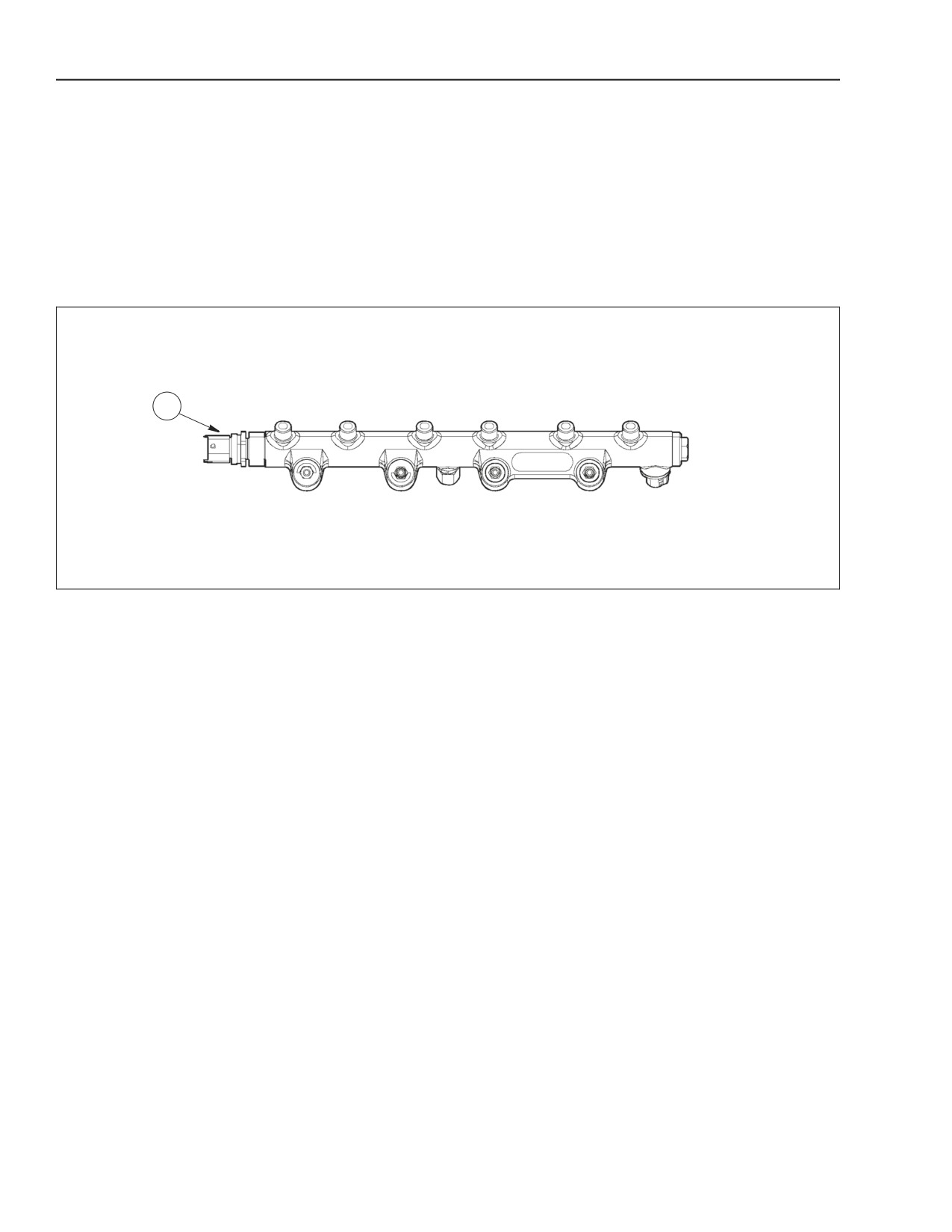
Figure 2-65
COMMON RAIL
A fuel rail pressure sensor (1) is screwed into the
The common rail volume is a high pressure fuel
common rail. The signal sent by this sensor to the
storage device. It has a small volume to allow a rapid
EDC7UC31 control unit, and is then feed back to the
pressurization at startup, at slow idle and in case of
common rail pressure sensor and corrected if
high flow rates.
necessary.
It has enough volume to minimize system spikes
caused by injector opening and closings and by the
high pressure pump operation. This function is
further enhanced by a calibrated orifice between the
high pressure pump and the common rail.
2-50
Issued 11-06
Bur
87519804 NA
ENGINE REPAIR MANUAL
CHAPTER 2 - 667TA ENGINE OVERHAUL
COMMON RAIL PRESSURE RELIEF VALVE
A
B
1
2
3
4
5
1
2
3
4
5
6
6
BS06K067
Figure 2-66
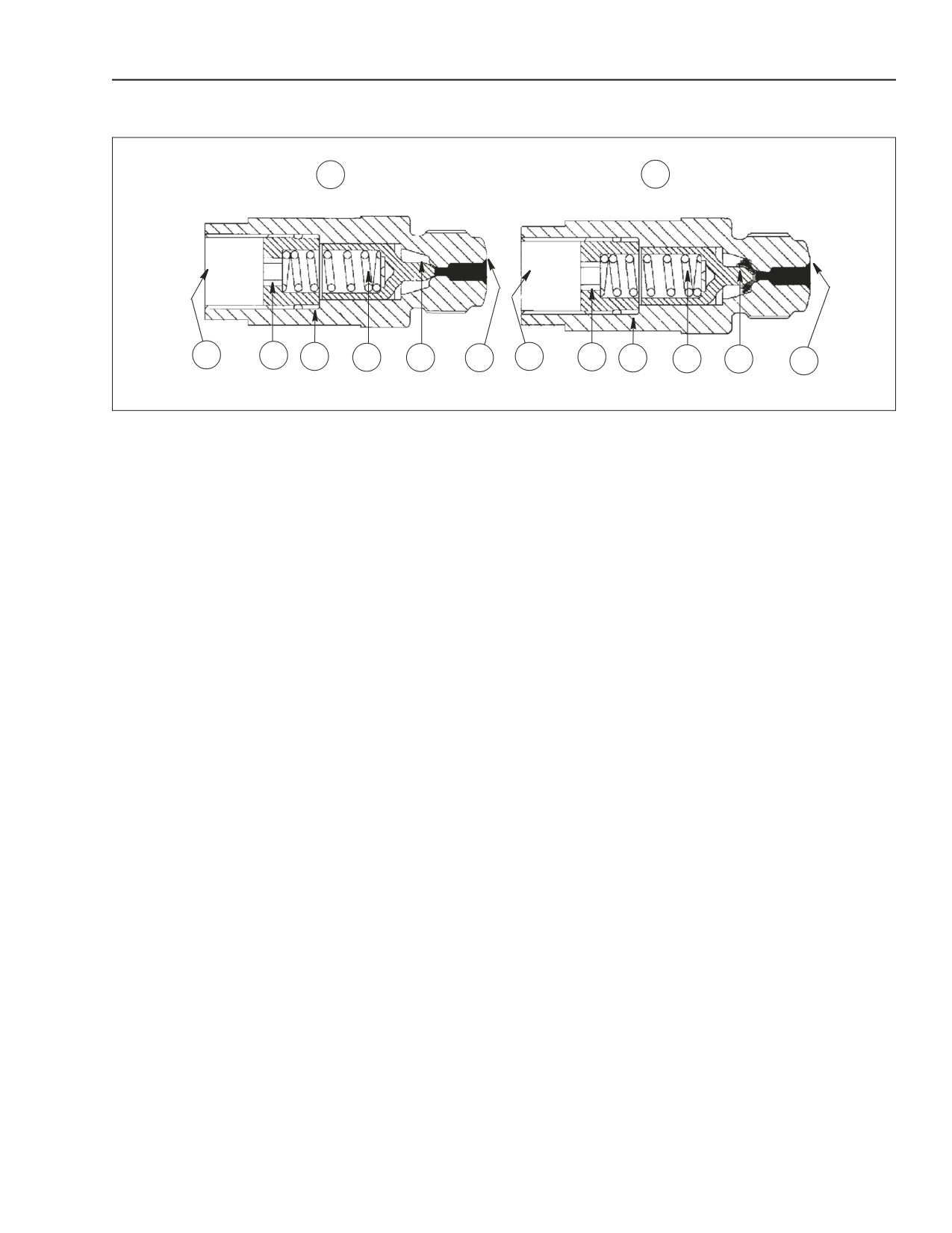
COMMON RAIL PRESSURE RELIEF VALVE
1. DIRECT TANK DISCHARGE
3. BODY
5. SMALL PISTON
2. STOP
4. SPRING
6. SEAT ON RAIL
A. NORMALLY, THE TAPERED PISTON (5) END STAYS CLOSED THE
DISCHARGE IS DIVERTED TO THE FUEL TANK.
B. IF 1750 BAR FUEL PRESSURE IS EXCEEDED IN THE RAIL, THE SMALL
PISTON MOVES AND THE EXCESS PRESSURE IS DISCHARGED INTO
THE FUEL TANK.
The common rail pressure relief valve is installed at
The relief valve enables engine operation at limited
one end of the common rail, it is designed to protect
performance, avoiding fuel overheating and
the systems components in case of excessive
safeguarding the system
increase of pressure buildup.
If the dual stage relief valve opening pressure is
The valve can be single stage (as the ones shown
reached, the EDC7UC31 control unit stops operation
above) or two stage with two working limits for
of the pressure regulator. The high pressure pump
pressure relief 1750 bar and 800 bar (25381 psi. and
will then operate at maximum delivery to the common
11603 psi.).
rail, and a failure code will be stored.
In the second case, when the pressure within the
high pressure system reaches 1750 bar (25381 psi.),
the valve is activated as a single stage one to
exhaust the fuel and consequently reduce the
pressure until reaching the proper pressure. Then it
reduces the pressure into the common rail to
approximately 800 bar (11603 psi.).
87519804 NA
Issued 11-06
Bur
2-51
ENGINE REPAIR MANUAL
CHAPTER 2 - 667TA ENGINE OVERHAUL
ELECTRO-INJECTOR
13
13
6
6
4
4
9
5
5
9
7
7
15
15
10
10
12
1
12
1
11
11
14
14
2
2
8
8
3
3
BS06K069
Figure 2-68
BS06K068
Figure 2-67
INJECTION START
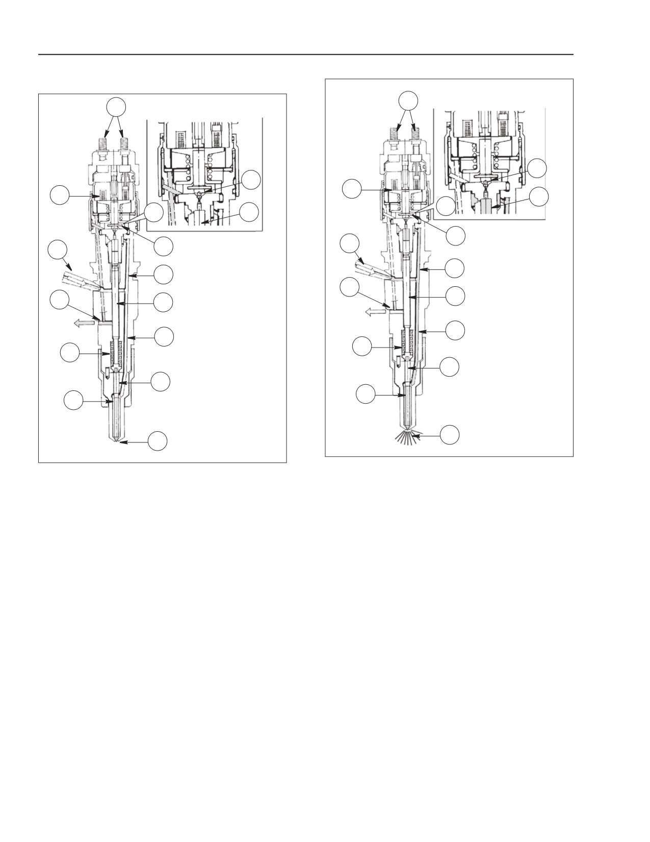
INJECTOR IN REST POSITION
When coil (4) is energized, it makes ball shutter (6)
1. PRESSURE ROD
9. CONTROL VOLUME
move upwards. The control volume (9) fuel flows
2. PLUNGER
10. CONTROL DUCT
towards control fuel outlet (12) making a pressure
3. NOZZLE
11. SUPPLY DUCT
drop occur in control volume (9). Simultaneously the
4. COIL
12. CONTROL FUEL OUTLET
fuel pressure into pressure chamber (8) makes
5. PILOT VALVE
13. ELECTRIC CONNECTION
plunger (2) lift, causing injection of fuel into the
6. BALL SHUTTER
14. SPRING
cylinder.
15. HIGH PRESSURE FUEL
7. CONTROL AREA
INLET
8. PRESSURE CHAMBER
INJECTION END
When coil (4) is de-energized, shutter ball (6) goes
The injector is similar to the conventional injectors,
back to its closed position to restore a balance of
except for the absence of plunger return springs.
forces to make plunger (2) go back to its closed
The injector can be considered in terms of two basic
position and end the injection cycle.
parts:
IMPORTANT: The injector has no serviceable parts
• Actuator- spray nozzle composed of pressure rod
inside, so it is not repairable.
(1), plunger (2) and nozzle (3).
• Control solenoid valve composed of coil (4) and
pilot valve (5).
The solenoid valve controls spray nozzle plunger lift.
2-52
Issued 11-06
Bur
87519804 NA
ENGINE REPAIR MANUAL
CHAPTER 2 - 667TA ENGINE OVERHAUL
ELECTRO-INJECTOR
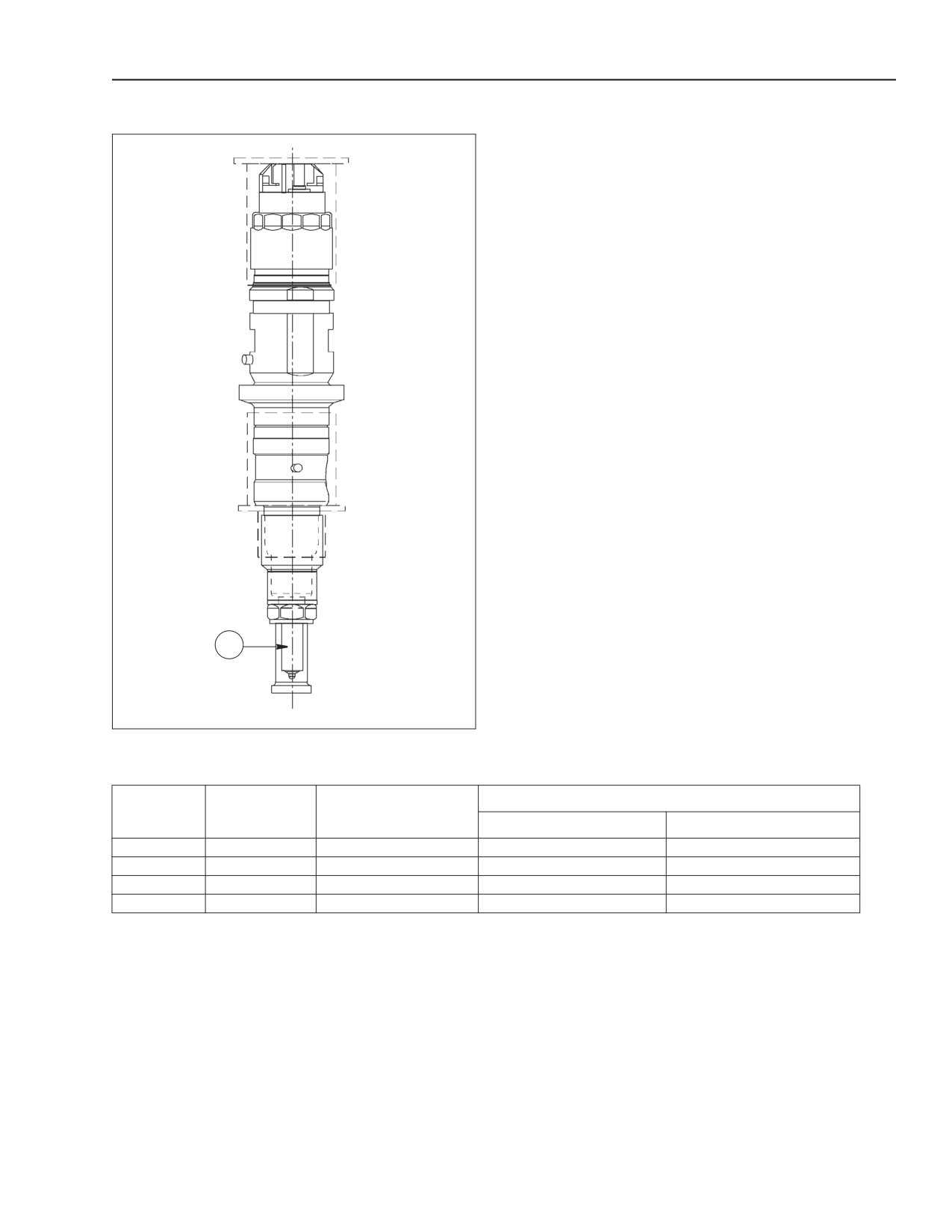
The injectors are Bosch CRIN 1 and CRIN 2. The jets
are installed according to power developed by the
engine.
1
BS06K070
Figure 2-69
1. JET
Pressures
Injectors
Jet
Engines
Minimal operating pressure
Nominal operating pressure
CRIN 1
not available
667TA/EEG - 667TA/EEC
not available
not available
CRIN 2
DLLA 137 PV 3
667TA/EBF - 667TA/EBD
250 bar (3626 psi.)
1600 bar (23206 psi.)
CRIN 2
DSLA 143 PV 3
667TA/EED
250 bar (3626 psi.)
1400 bar (20305 psi.)
CRIN 2
not available
667TA/EDJ
250 bar (3626 psi.)
1400 bar (20305 psi.)
87519804 NA
Issued 11-06
Bur
2-53
ENGINE REPAIR MANUAL
CHAPTER 2 - 667TA ENGINE OVERHAUL
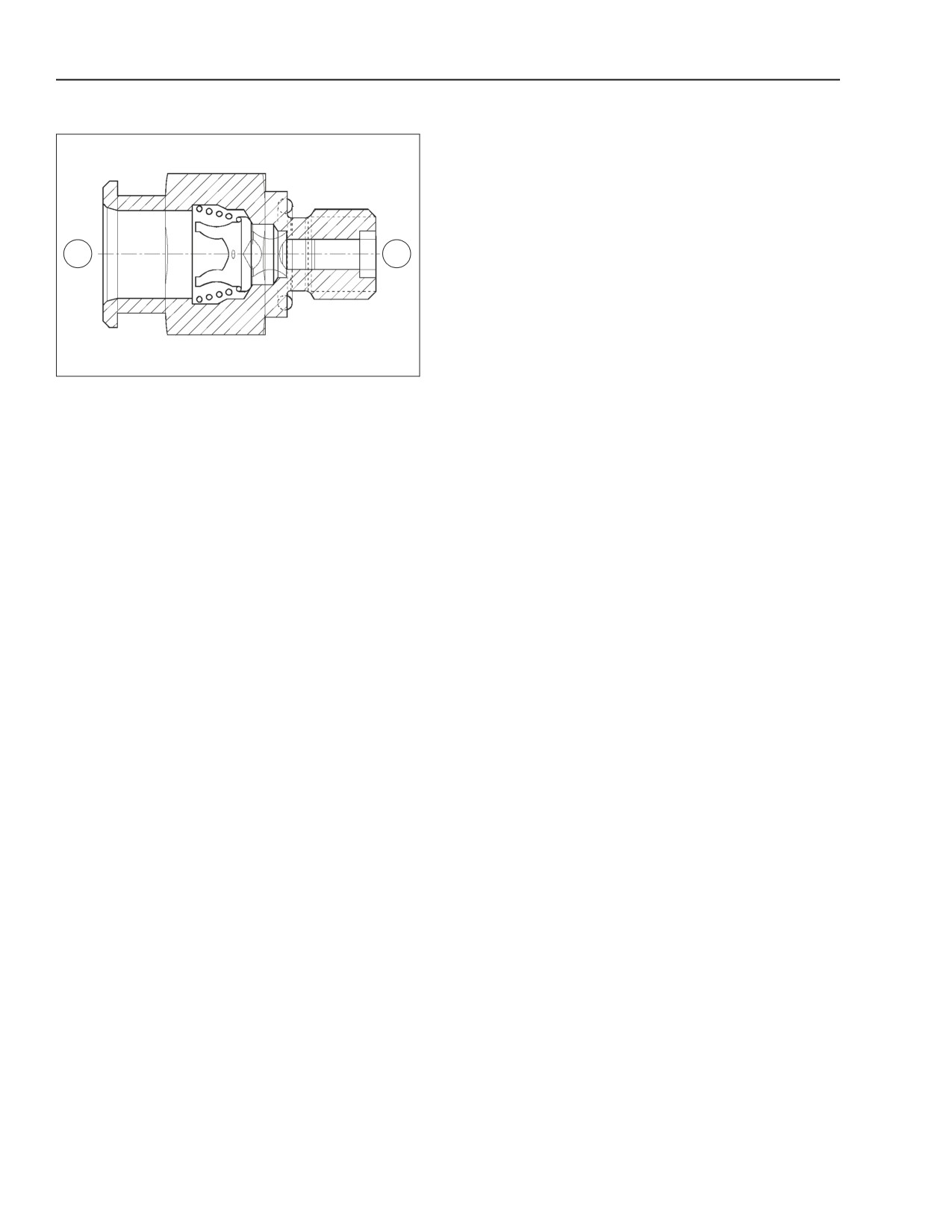
PRESSURE LIMITER FOR FUEL RETURN
A
B
BS06K071
Figure 2-70
A. TO FUEL TANK
B. FROM INJECTORS
The pressure limiter for the fuel return is housed on
the rear of the cylinder head, and adjusts the
pressure of the fuel returning from injectors at a
pressure of 1.3 to 2.0 bars (18.9 to 29 psi.). By
maintaining this pressure to the return fuel, the fuel
vapor formation inside the injectors is avoided,
optimizing fuel spraying and combustion.
2-54
Issued 11-06
Bur
87519804 NA
ENGINE REPAIR MANUAL
CHAPTER 2 - 667TA ENGINE OVERHAUL
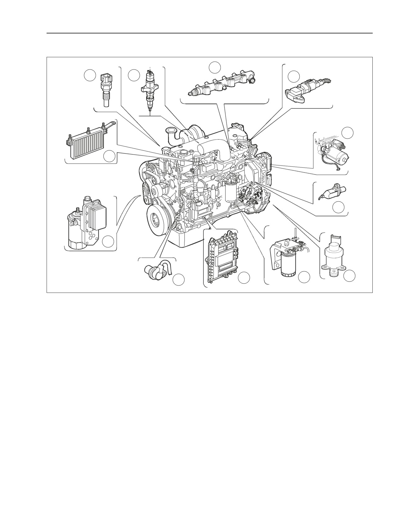
LOCATION OF THE MAIN ELECTRICAL COMPONENTS
3
1
2
4
5
12
6
11
9
8
7
10
BS06K072
Figure 2-71
1. COOLANT TEMPERATURE SENSOR
7.
SOLENOID VALVE FOR PRESSURE REGULATOR
2. ELECTRO-INJECTOR
8.
FUEL TEMPERATURE SENSOR
3. FUEL RAIL PRESSURE SENSOR
9.
EDC7UC31 ELECTRONIC CONTROL UNIT
4. BOOST TEMPERATURE/PRESSURE SENSOR
10.
CRANKSHAFT SENSOR
5. STARTER MOTOR
11.
ENGINE OIL PRESSURE/TEMPERATURE SENSOR
6. CAMSHAFT SENSOR
12.
HEATING ELEMENT FOR PRE-POST HEATING
The engine is controlled by the EDC7UC31
electronic control module. The control module is
installed on flexible mounts to reduce vibration
transmitted by the engine. The fuel heat exchanger
removes heat from the controller due to the high
voltages needed for firing the injectors. It removes
the heat from the controller and loses it in the fuel
cooler. It also picks up some engine heat when it is
returned from the cylinder head. The unit is supplied
with a 20 amp fuse. The main relay used to supply
the power to the system is located inside the control
unit.
Through the engine control module, it is possible to
verify the correct operations of the engine and also
help troubleshoot problems with error codes
generated from the EDC7UC31 control module.
87519804 NA
Issued 11-06
Bur
2-55
ENGINE REPAIR MANUAL
CHAPTER 2 - 667TA ENGINE OVERHAUL
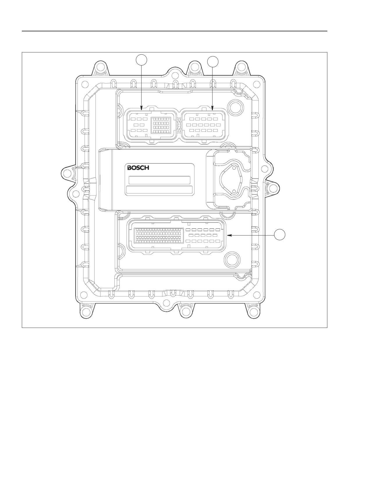
EDC7UC31 ELECTRONIC CONTROL UNIT
C
A
B
BS06K073
Figure 2-72
EDC7UC31 ELECTRONIC CONTROL UNIT
A. CONNECTOR TO INJECTORS
B. CONNECTOR FOR POWER INPUT AND FUNCTIONS PROVIDED FOR IN THE APPLICATION
C. CONNECTOR TO SENSORS
2-56
Issued 11-06
Bur
87519804 NA
ENGINE REPAIR MANUAL
CHAPTER 2 - 667TA ENGINE OVERHAUL
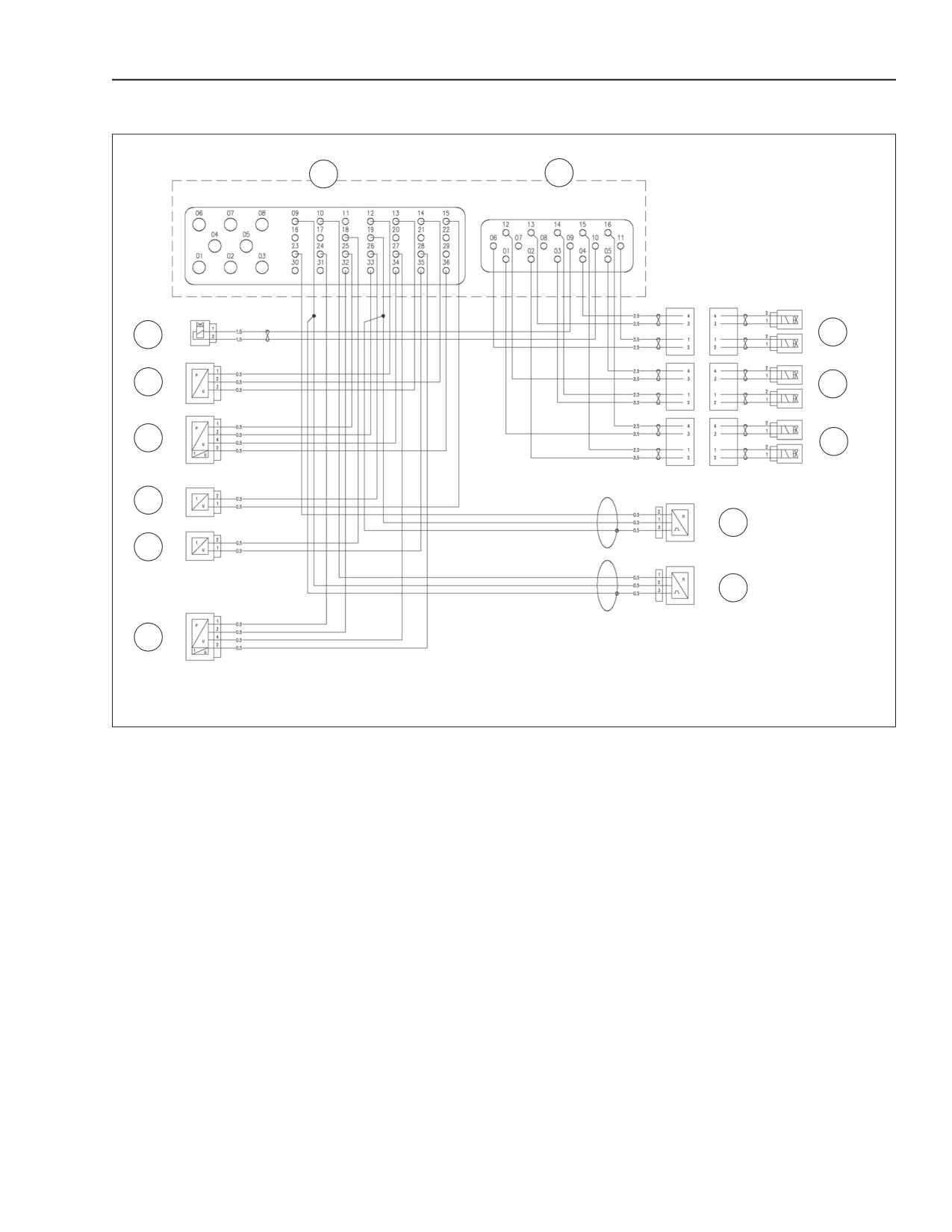
CABLING CONNECTOR PINOUT ON ENGINE
C
A
11
1
10
2
9
3
8
4
7
5
6
BS06K074
Figure 2-73
CONNECTOR / CABLING DIAGRAM
A. CONNECTOR A (INJECTORS) EDC7UC31 ECU (POWER) 5. CAMSHAFT SENSOR
B. CONNECTOR B NOT SHOWN (SEE NOTE BELOW)
6. OIL PRESSURE AND TEMPERATURE SENSOR
C. CONNECTOR C (SENSORS) EDC7UC31 ECU (SIGNAL)
7. FUEL TEMPERATURE
1. INJECTORS FOR CYLINDERS 1-2
8. COOLANT TEMPERATURE SENSOR
2. INJECTORS FOR CYLINDERS 3-4
9. BOOST AIR TEMPERATURE AND PRESSURE SENSOR
3. INJECTORS FOR CYLINDERS 5-6
10. COMMON RAIL PRESSURE SENSOR
4. CRANKSHAFT SENSOR
11. FUEL HIGH PRESSURE REGULATOR SENSOR
NOTE: Connector B is not shown because it is specific to the machine application see the particular machine
schematic.
87519804 NA
Issued 11-06
Bur
2-57
ENGINE REPAIR MANUAL
CHAPTER 2 - 667TA ENGINE OVERHAUL
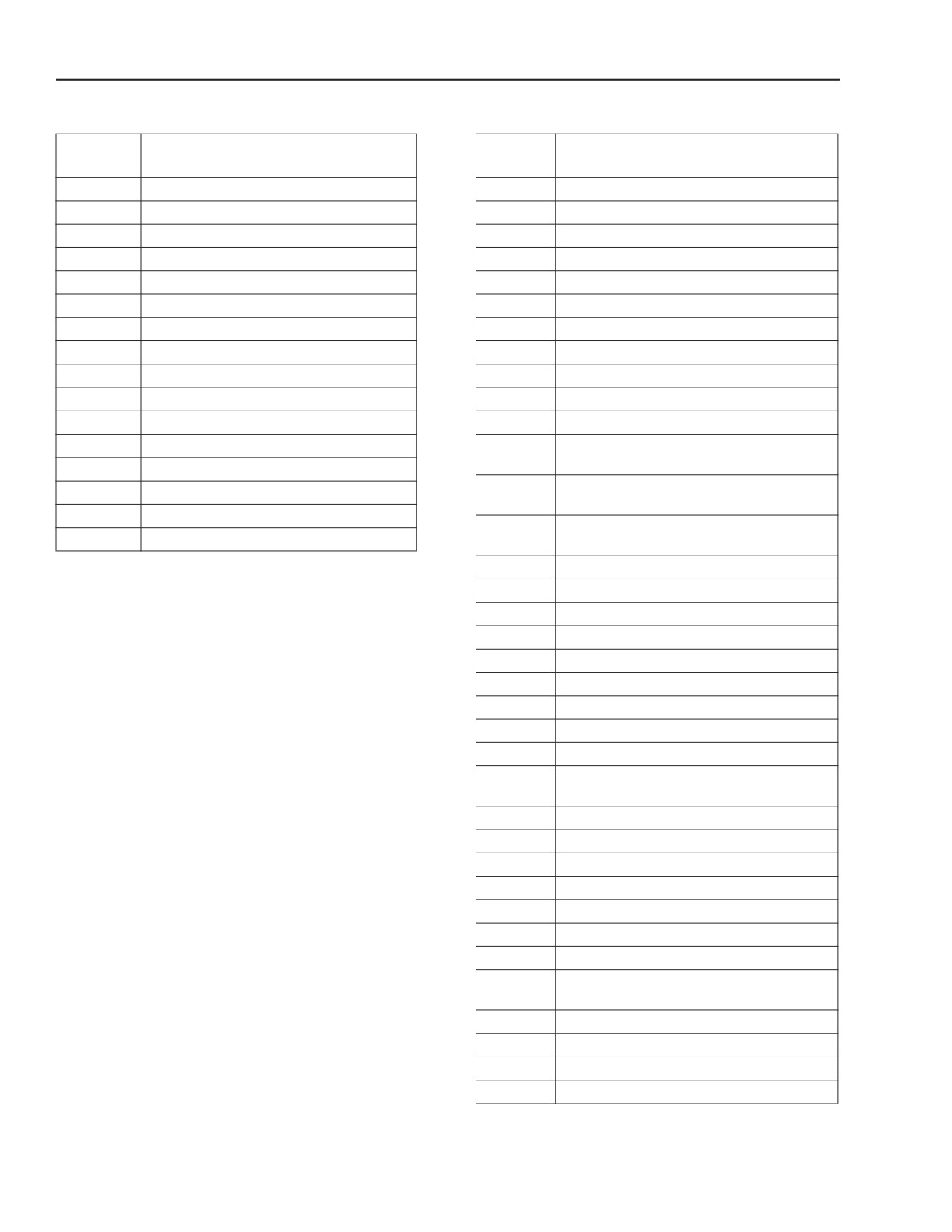
CONNECTOR (A) INJECTORS PINOUT DIAGRAM
CONNECTOR (C) SENSORS PINOUT DIAGRAM
EDC7UC31
EDC7UC31
FUNCTION
FUNCTION
ECU PIN
ECU PIN
1.
Cylinder 5 injector
1.
Not Used
2.
Cylinder 6 injector
2.
Not Used
3.
Cylinder 4 injector
3.
Not Used
4.
Cylinder 1 injector
4.
Not Used
5.
Cylinder 3 injector
5.
Not Used
6.
Cylinder 2 injector
6.
Not Used
7.
not used
7.
Not Used
8.
not used
8.
Not Used
9.
High pressure regulator with fuel metering
9.
Camshaft speed sensor - Signal
10.
High pressure regulator with fuel metering
10.
Camshaft speed sensor - Ground
11.
Cylinder 2 injector
11.
Not Used
12.
Cylinder 3 injector
12.
Common rail temperature and pressure
sensor - Ground
13.
Cylinder 1 injector
13.
Common rail temperature and pressure
14.
Cylinder 4 injector
sensor - Positive
15.
Cylinder 6 injector
14.
Common rail temperature and pressure
16.
Cylinder 5 injector
sensor - Signal
15.
Coolant temperature sensor - Signal
16.
Not Used
17.
Not Used
NOTE: Connector B is not shown because it is
specific to the machine application see the particular
18.
Fuel temperature sensor - Signal
machine schematic.
19.
Crankshaft speed sensor - Ground
20.
Not Used
21.
Not Used
22.
Not Used
23.
Crankshaft speed sensor - Signal
24.
Engine oil pressure and temperature sensor -
Ground
25.
Boost intake pressure sensor - Ground
26.
Coolant temperature sensor - Ground
27.
Oil pressure sensor - Signal
28.
Oil temperature sensor- Signal
29.
Not Used
30.
Not Used
31.
Not Used
32.
Engine oil pressure and temperature sensor -
Positive
33.
Boost intake pressure sensor - Positive
34.
Boost intake pressure sensor - Signal
35.
Fuel temperature sensor - Signal
36.
Boost intake temperature sensor - Signal
2-58
Issued 11-06
Bur
87519804 NA
ENGINE REPAIR MANUAL
CHAPTER 2 - 667TA ENGINE OVERHAUL
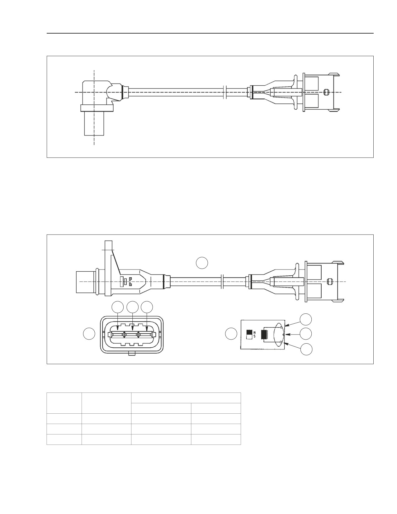
CRANKSHAFT SENSOR
BS06K075
Figure 2-74
CRANKSHAFT SENSOR
The crankshaft sensor is an inductive sensor located
The crankshaft sensor is connected to the
at the front left hand side of the engine. The
EDC -7 control unit on pins 19C - 23C. The sensor
crankshaft sensor produces signals obtained from
impedance is approximately 900 ohms.
magnetic flux field through the openings in a phonic
wheel fitted on the crankshaft.
CAMSHAFT SENSOR
A
3
2
1
1
B
C
2
3
BS06K076
Figure 2-75
A. CAMSHAFT SENSOR
B. CONNECTOR
C. WIRING DIAGRAM
EDC7UC31 ECU
Reference
Description
Camshaft sensor
Timing sensor
1
Signal
19C
10C
2
Signal
23C
9C
3
Shield
87519804 NA
Issued 11-06
Bur
2-59
ENGINE REPAIR MANUAL
CHAPTER 2 - 667TA ENGINE OVERHAUL
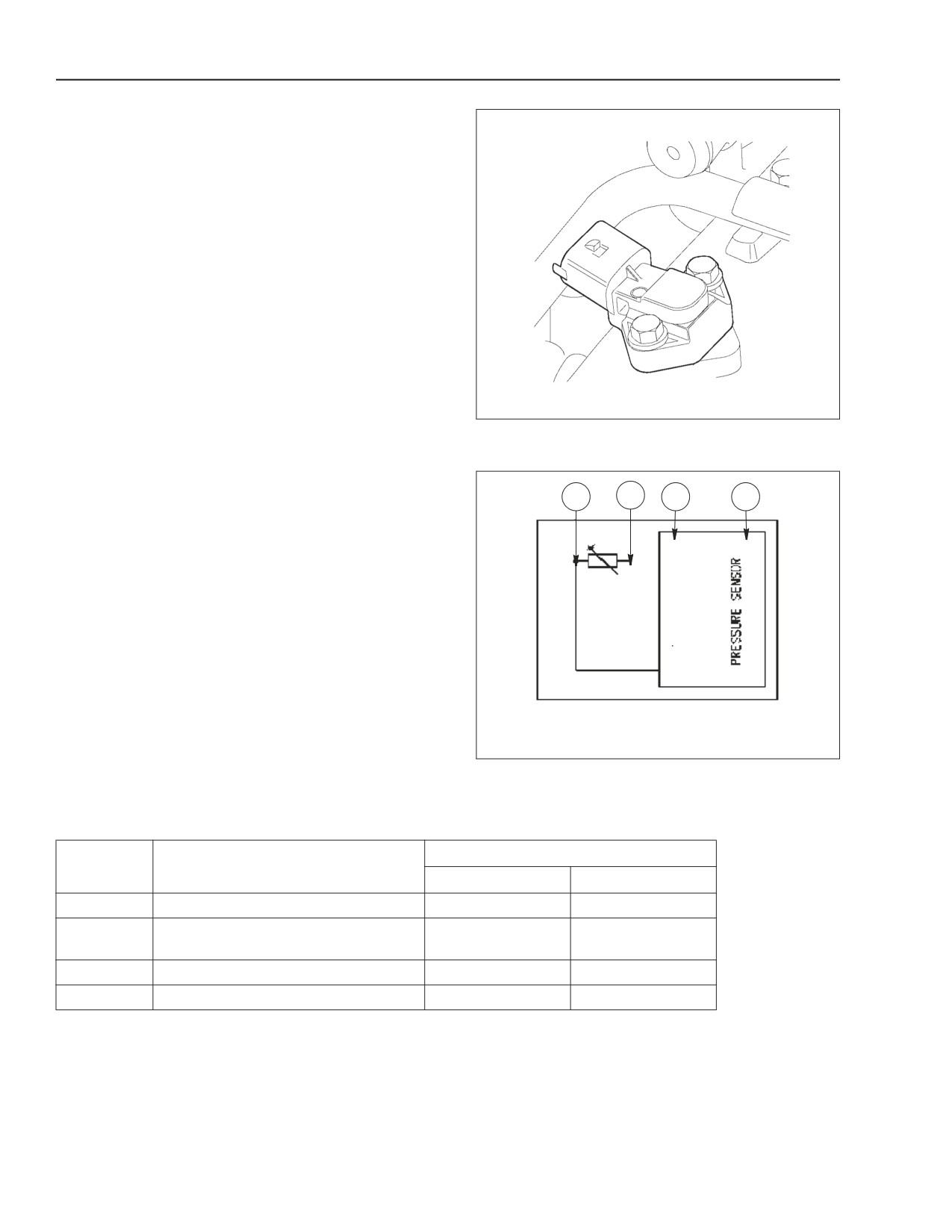
BOOST TEMPERATURE - PRESSURE SENSOR
This component incorporates a temperature sensor
and a pressure sensor all in one unit.
Installed on the intake manifold, the sensor
measures the temperature and boost pressure,
which serves to make an accurate calculation of the
quantity of fuel to be injected in each cycle.
The sensor is connected to the EDC7UC31
electronic control unit on pins 25C - 36C - 33C - 34C.
The sensor is supplied with 5 volts.
Voltage at the sensor output is proportional to the
detected pressure or temperature.
• Pin 25C - 36C Temperature
• Pin 33C - 34C Pressure
BS06K077
Figure 2-76
ENGINE OIL TEMPERATURE - PRESSURE
SENSOR
PRESSURE - TEMPERATURE SENSOR
This component incorporates a temperature sensor
and a pressure sensor all in one unit.
1
2
3
4
The engine oil temperature-pressure sensor is
installed on the engine oil filter bracket in a vertical
position. This sensor measures the engine oil
temperature and pressure.
The sensor is connected to the EDC7UC31
electronic control unit on pins 24C - 28C - 32C - 27C.
The sensor is supplied with 5 volts. The pressure
signal is transmitted to the EDC7UC31 electronic
control unit which in turn, sends a signal to the
instrument panel gauge and low pressure warning
light.
The oil temperature is not displayed on any gauges
this value is used exclusively by the control unit.
BS06K078
Figure 2-77
Pin 24C - 28C Temperature
Pin 32C - 27C Pressure
EDC7UC31 Control unit pin number
Reference
Description
Oil
Air
1
Ground
24C
25C
EDC7UC31 control unit- Signal
2
28C
36C
(temperature)
3
+5 volt power supplied to sensor
32C
33C
4
Signal (pressure)
27C
34C
2-60
Issued 11-06
Bur
87519804 NA
ENGINE REPAIR MANUAL
CHAPTER 2 - 667TA ENGINE OVERHAUL
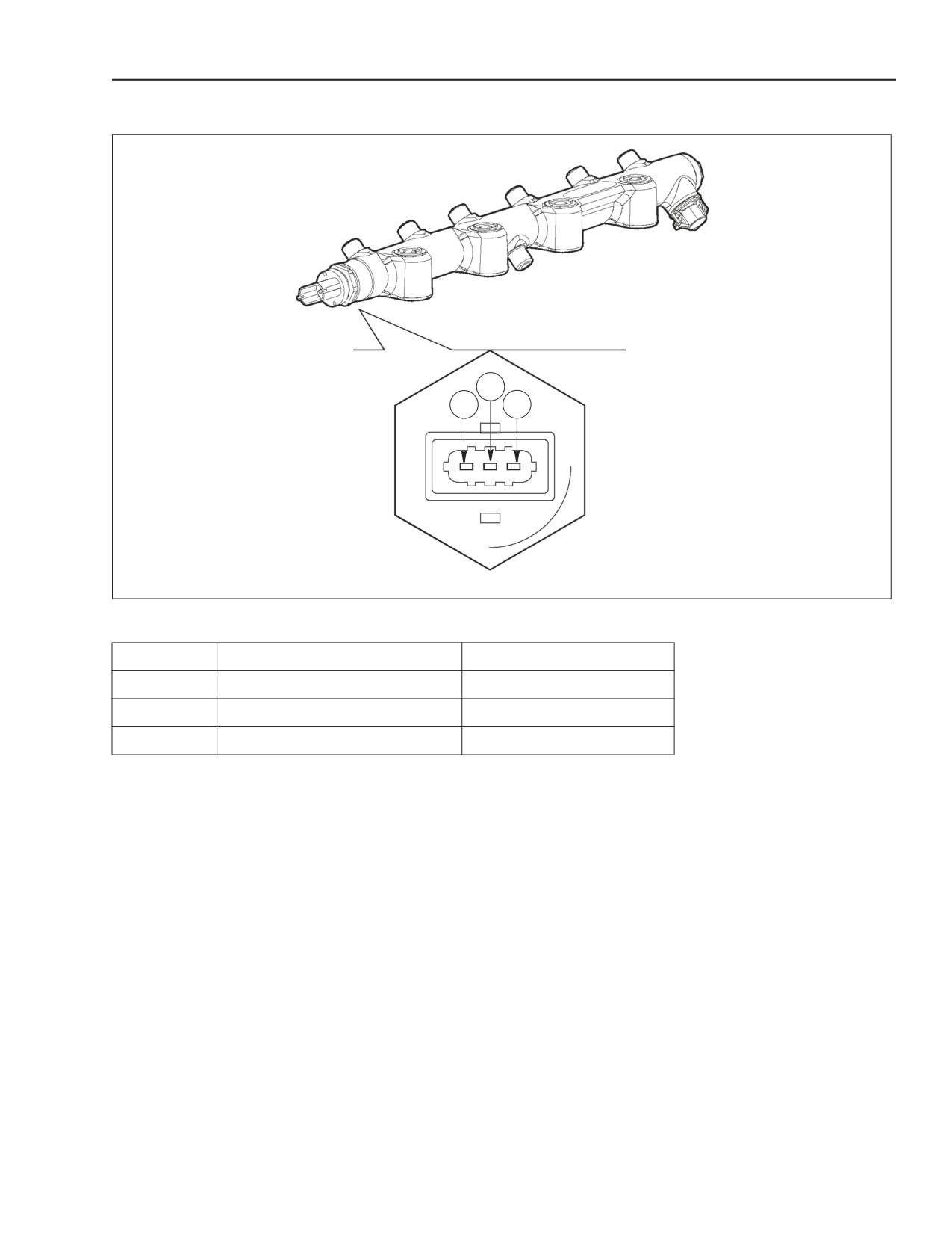
COMMON RAIL FUEL PRESSURE SENSOR
2
1
3
BS06K079
Figure 2-78
COMMON RAIL FUEL PRESSURE SENSOR CONNECTOR
Reference
Description
EDC7UC31 control unit pin
1
Ground
12C
2
Signal
14C
3
Power supply
13C
The fuel rail pressure sensor is installed on one end
This sensor is connected to the EDC7UC31 control
of the common rail, this sensor measures the internal
unit on pins 12C - 14C - 13C.
fuel pressure and feeds back this information to the
The power supplied to sensor is 5 volts.
EDC7UC31 control unit.
The injection pressure value is used as a pressure
control feedback signal and to determine the duration
of the electrical pulse for the injection command.
87519804 NA
Issued 11-06
Bur
2-61
ENGINE REPAIR MANUAL
CHAPTER 2 - 667TA ENGINE OVERHAUL
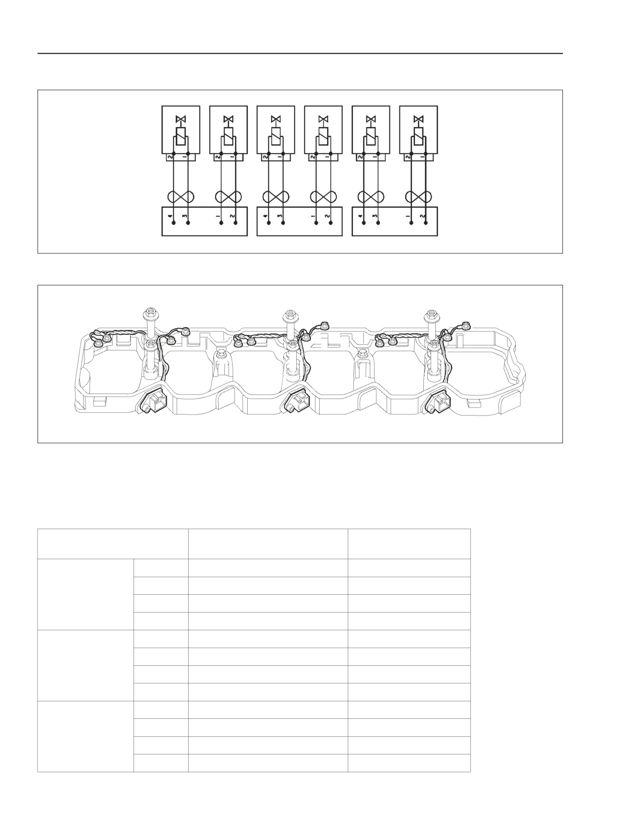
ELECTRO-INJECTORS
BS06K080
Figure 2-79
INJECTOR WIRE HARNESS LAYOUT
BS06K081
Figure 2-80
INJECTOR WIRE HARNESS
The electro-injectors are a normally Closed (N.C.)
The impedance of the coil of each injector is 0.56 -
solenoid valve.
0.57 ohms.
Each injector is connected to the EDC7UC31 control
unit on connector A.
EDC7UC31 control
Reference
Description
unit pin
1
Cylinder 2 injector
11A
2
Cylinder 2 injector
6A
CONNECTOR 1
3
Cylinder 1 injector
13A
4
Cylinder 1 injector
4A
1
Cylinder 4 injector
14A
2
Cylinder 4 injector
3A
CONNECTOR 2
3
Cylinder 3injector
12A
4
Cylinder 3 injector
5A
1
Cylinder 6 injector
15A
2
Cylinder 6 injector
2A
CONNECTOR 3
3
Cylinder 5 injector
1A
4
Cylinder 5 injector
16A
2-62
Issued 11-06
Bur
87519804 NA
ENGINE REPAIR MANUAL
CHAPTER 2 - 667TA ENGINE OVERHAUL
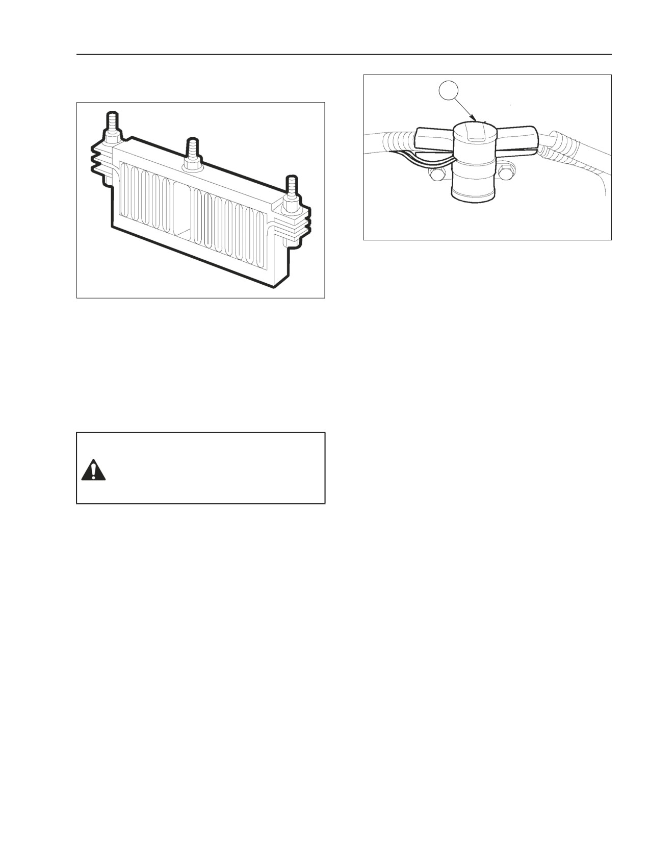
INTAKE AIR PRE-POST RESISTANCE HEATER
AND RELAY
A
BS06K083
Figure 2-82
GRID PLATE HEATER CONTROL RELAY
The control relay is connected to the EDC7UC31
control unit B connector.
BS06K082
Figure 2-81
The relay is tripped with water and or fuel
GRID PLATE HEATER
temperature below 5° C (41° F).
The pre-post grid plate heater is located on the
The relay impedance is approximately 15 ohms.
intake manifold.
The purpose of the grid plate heater is to heat the air
in pre-post heating operations. The grid plate heater
is powered by a relay on the chassis.
The impedance of the grid plate heater is
approximately 0.5 ohms.
WARNING: Starting fluids or aids, such as
ether, must not be used to help start this
engine. The use of these starting fluids or
aids will cause severe internal damage to the
engine and can also cause personal injury.
50-41
87519804 NA
Issued 11-06
Bur
2-63
ENGINE REPAIR MANUAL
CHAPTER 2 - 667TA ENGINE OVERHAUL
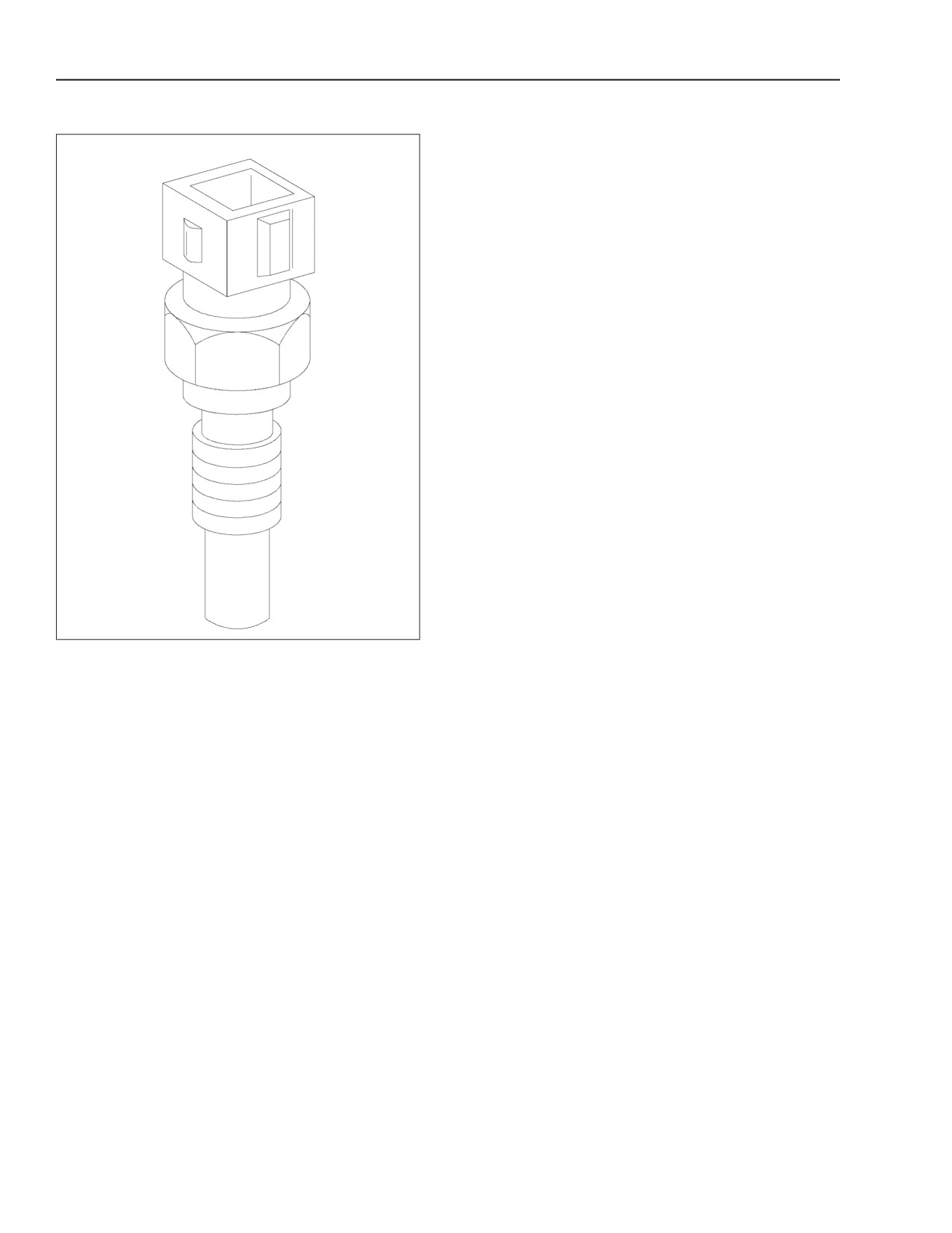
COOLANT TEMPERATURE SENSOR
BS06K209
Figure 2-83
COOLANT TEMPERATURE SENSOR
The coolant temperature sensor is a variable
resistance sensor able to read the coolant
temperature in order to provide the EDC7UC31
control unit with an indication of the temperature
status of the engine.
The same signal is utilized by the control unit to drive
an instrument panel gauge, if present.
This sensor is connected to the EDC7UC31 control
unit on pins 15C - 26C.
The impedance of the coolant temperature sensor at
20° C (68° F) is approximately 2.5 k (2500) ohms.
2-64
Issued 11-06
Bur
87519804 NA
ENGINE REPAIR MANUAL
CHAPTER 2 - 667TA ENGINE OVERHAUL
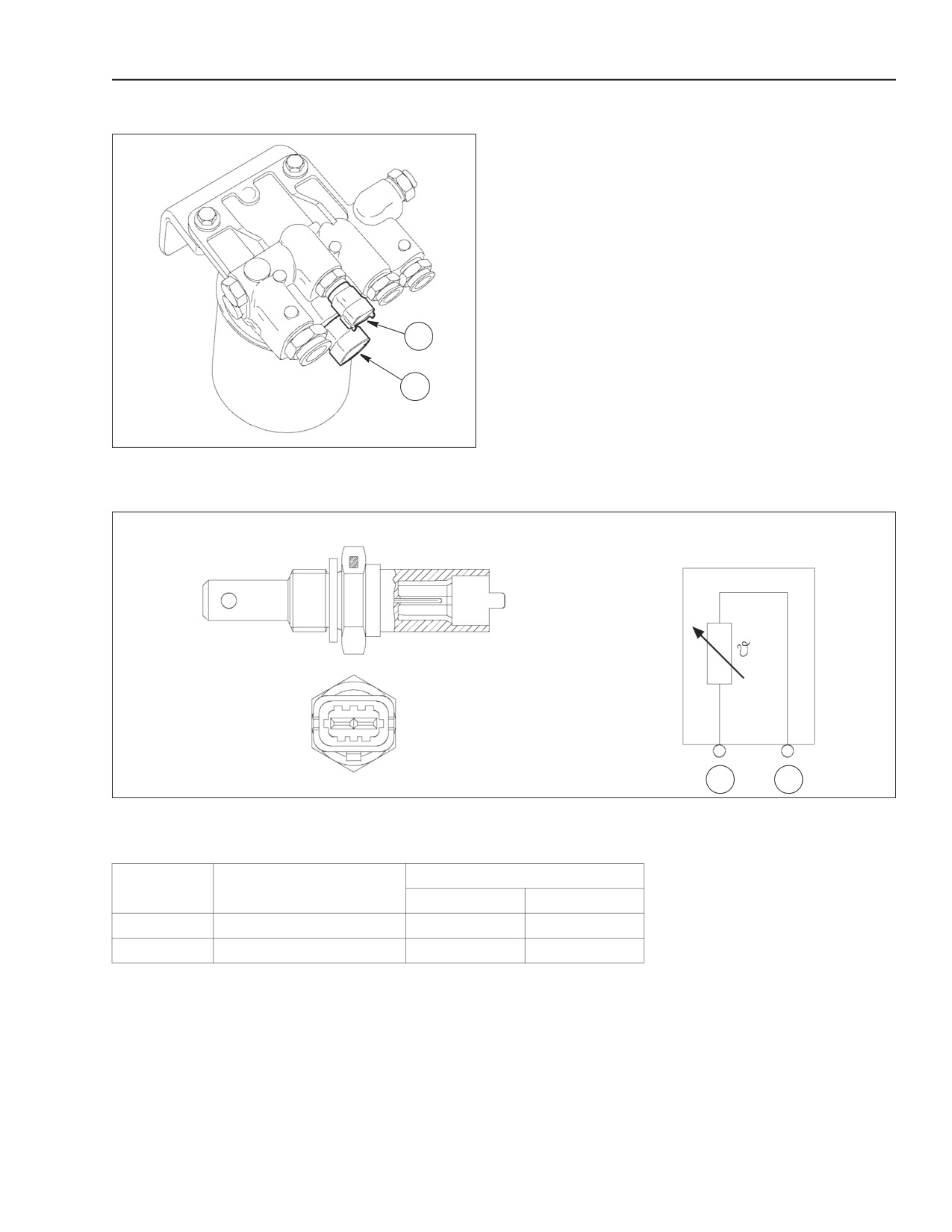
FUEL TEMPERATURE SENSOR
This sensor detects the fuel temperature so the
EDC7UC31 control unit can precisely inject the fuel
required.
The fuel temperature sensor is connected to the
EDC7UC31 control unit on pins 35C - 18C.
The sensor impedance at 20° C (68° F) is
approximately 2.5 k (2500) ohms.
1
2
BS06K210
Figure 2-84
1. FUEL TEMPERATURE SENSOR
2. FILTER HEATER RELAY
1
2
BS06K211
Figure 2-85
FILTER HEATER RELAY
The EDC7UC31 control unit activates the filter heater relay when fuel temp drops below 5° C (41° F)
EDC7UC31 Control unit Pin
Reference
Description
Coolant
Fuel
1
Ground
15C
35C
2
Temperature Signal
26C
18C
87519804 NA
Issued 11-06
Bur
2-65