New Holland 667TA/EEG, 667TA/EEC, 667TA/EBF, 667TA/EED, 667TA/EBJ, 667TA/EDJ. ENGINE REPAIR MANUAL (2006) - page 4
ENGINE REPAIR MANUAL
CHAPTER 2 - 667TA ENGINE OVERHAUL
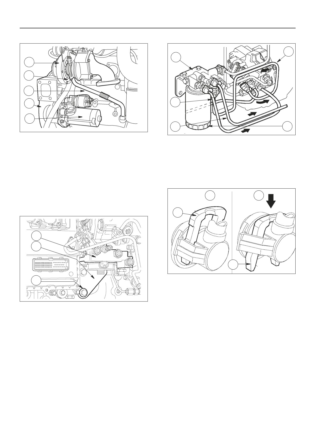
STEP 119
STEP 121
3
4
1
1
5
2
4
3
2
6
BS06K349
Figure 2-222
BS06K347
Figure 2-220
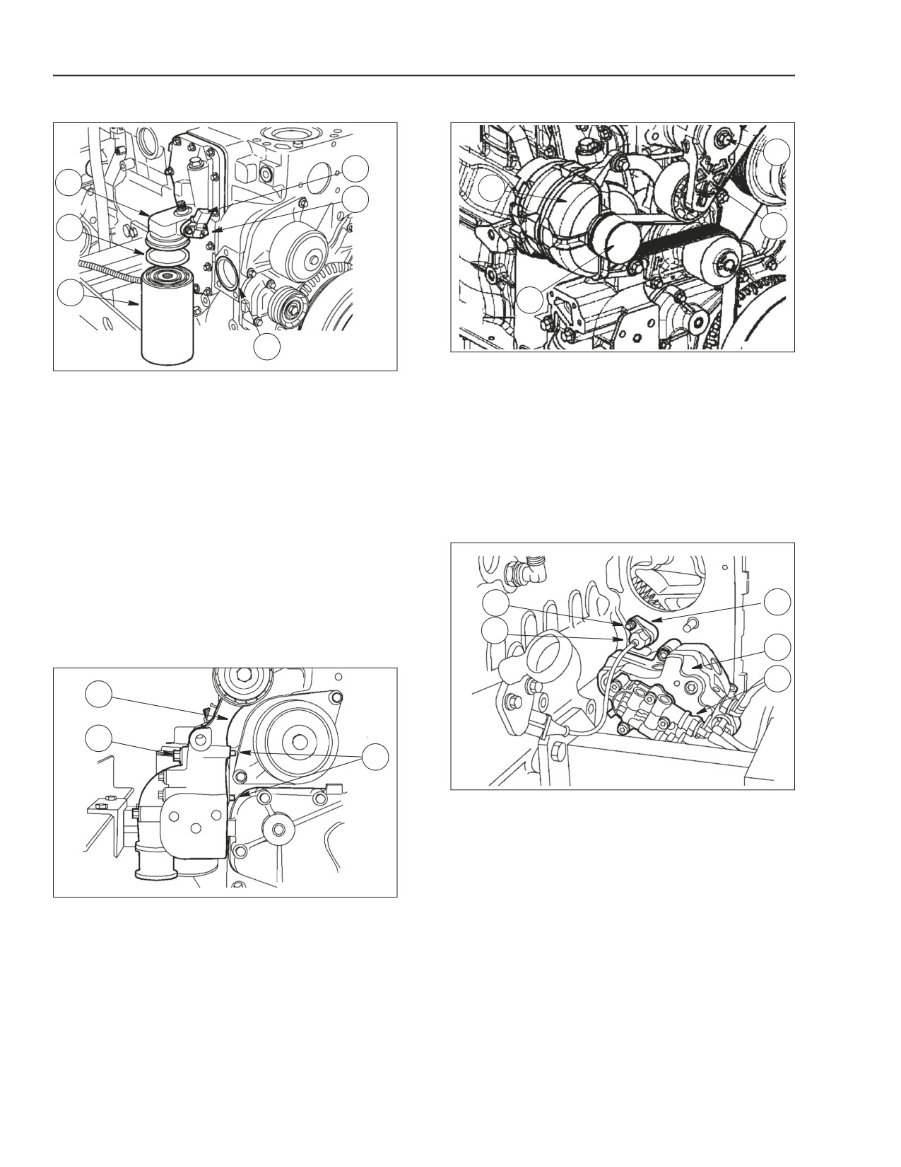
Reconnect alternator (1) and tighten the bolts to 40
Lubricate the sealing ring (2) with engine oil and set it
to 50 Nm (29.5 to 36.9 lb.-ft.) the specified torque.
on the oil filter (3).
Reconnect automatic tensioner (4) and tighten bolt
Screw oil filter (3) on the oil filter bracket (1) till
(3) to 40 to 50 Nm (29.5 to 36.9lb.-ft.)specified
gasket makes contact with bracket and then tighten
torque.
an additional 3/4 turn (except for 667TA/EEG and
Turn the automatic belt tensioner (4) to install the belt
667TAEEC engines)
(2) on pulleys and guide rollers.
Apply a new sealing ring on the oil temperature/
STEP 122
pressure sensor (4) and install it on oil filter bracket
(1).
Tighten bolts (5) to 20 Nm (14.8 lb.-ft.) max the
specified torque.
1
3
Install a new sealing ring (6) in the engine block seat.
2
STEP 120
4
5
1
2
3
BS06K350
Figure 2-223
Install the high pressure pump (4) including the feed
pump (5) and tighten the nuts to the specified torque.
Install the support (3) with a new sealing ring, the
timing sensor (2) with a new sealing ring and tighten
the fastening nut (1), to the general bolt torque
BS06K348
Figure 2-221
specifications in the repair manual.
Position the alternator support (1) so that pins (3) are
set against the engine block.
Tighten the bolts (2) to 40 to 50 Nm (29.5 to 36.9 lb.-
ft.) the specified torque.
2-106
Issued 11-06
Bur
87519804 NA
ENGINE REPAIR MANUAL
CHAPTER 2 - 667TA ENGINE OVERHAUL
STEP 123
STEP 125
1
2
1
3
2
3
4
5
BS06K351
Figure 2-224
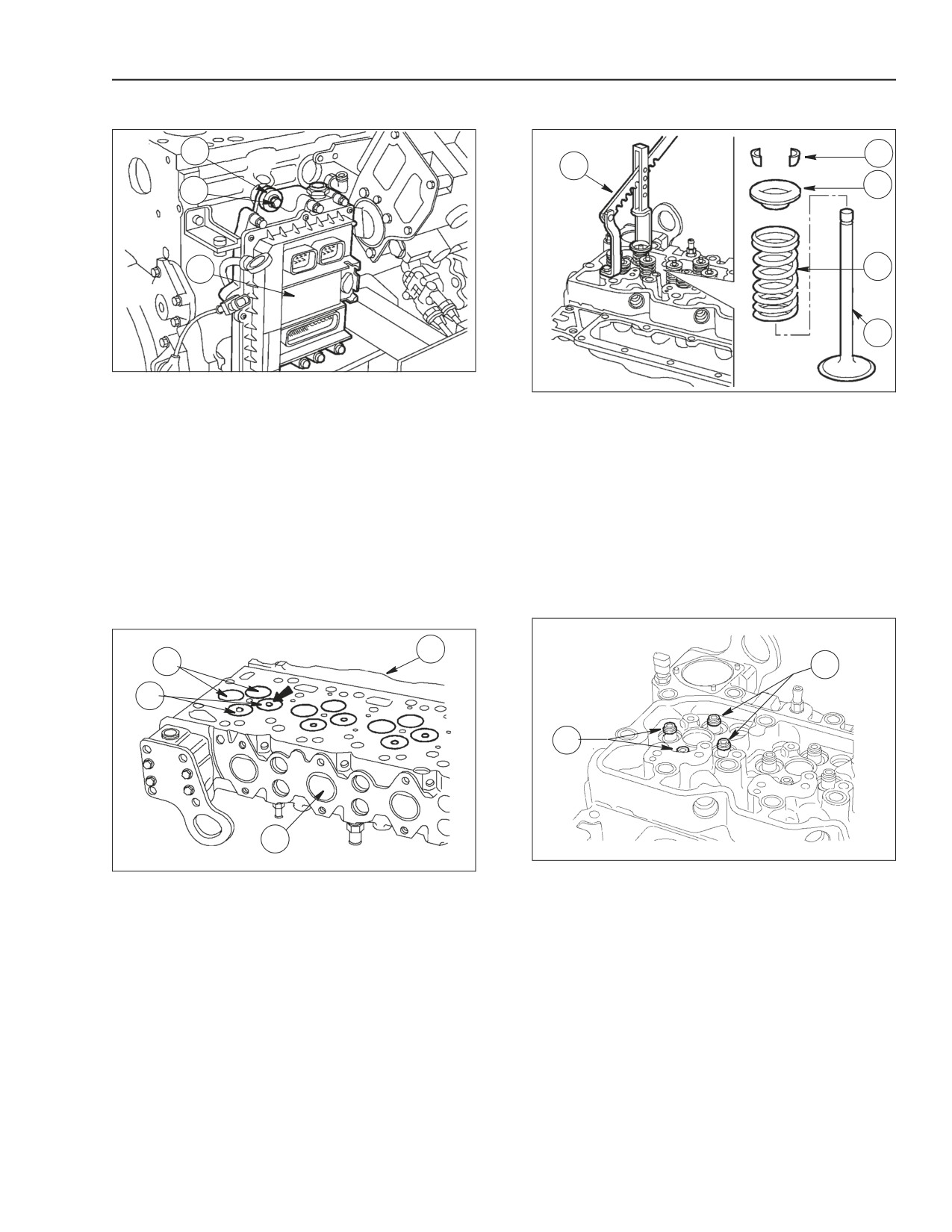
Install the EDC7UC31 electronic control unit (3)
BS06K353
Figure 2-226
including the heat exchanger to the engine block and
Valves can be removed with a valve spring
tighten the bolts (2), to the general bolt torque
compressor tool (1) by pressing slightly on collar (3)
specifications in the repair manual.
so that lock cones (2) can be removed by
compressing springs (4).
IMPORTANT: Replace the vibration damper
elements (1).
Then remove collar (3) and springs (4).
Repeat the operation on all valves.
CYLINDER HEAD
Turn the head upside down and remove the valves
(5).
REMOVING THE VALVES
STEP 126
STEP 124
A
1
2
2
1
S
BS06K354
Figure 2-227
BS06K352
Figure 2-225
Remove the sealing rings (1 and 2) from the valve
Intake (1) and exhaust (2) valves have heads with
guides.
the same diameter.
IMPORTANT: Sealing rings (1) for intake valves are
The central notch (→) of the exhaust valve (2) head
yellow.
distinguishes it from the intake valve.
Sealing rings (2) for exhaust valves are green.
IMPORTANT: Should cylinder head valves not be
replaced, number them before removing in order to
install them in the same position.
A = Intake side S = Exhaust side
87519804 NA
Issued 11-06
Bur
2-107
ENGINE REPAIR MANUAL
CHAPTER 2 - 667TA ENGINE OVERHAUL
CHECKING CYLINDER HEAD WATER SEAL
STEP 129
STEP 127
BS06K357
Figure 2-230
1
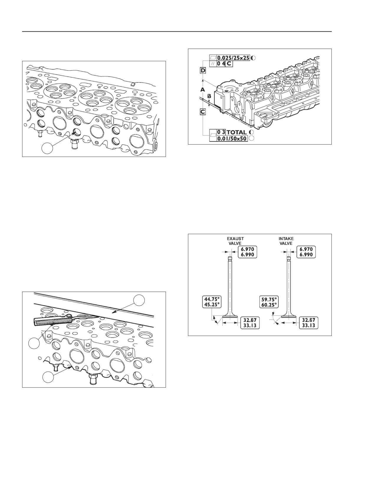
The rated thickness "A" of the cylinder head is 105 ±
BS06K355
Figure 2-228
0.25mm (4.134 ± 0.0099 in.). Maximum allowed
Check the water seal by means of suitable
metal removal must not exceed thickness "B" by
equipment.
0.13 mm (0.005 in.).
Use pump to feed water heated to 90° C (194° F) at a
pressure of 2 to 3 bar (29 to 43 psi.)
IMPORTANT: After grinding, check valve sinking.
Regrind the valve seats if necessary, to obtain the
If leaks are detected from the freeze plugs, they must
specified value
be replaced by using a suitable beater for removal
and reassembling operations.
VALVES
IMPORTANT: Prior to installing the freeze plugs,
apply water repellent sealant to them.
If leaks are detected from the cylinder head, the
cylinder head must be replaced.
CHECKING THE CYLINDER HEAD MATING
SURFACE
STEP 128
2
BS06K358
Figure 2-231
3
INTAKE AND EXHAUST VALVE MAIN DATA
1
BS06K356
Figure 2-229
The plane of the supporting surface of the head (1) to
cylinder cluster is checked by means of a straight
edge (2) and a thickness gauge (3).
The warping found on the entire length of the cylinder
head must not be greater than 0.20mm (.0.008 in.).
If greater values are found, reface the cylinder head
according to values given in the next step.
2-108
Issued 11-06
Bur
87519804 NA
ENGINE REPAIR MANUAL
CHAPTER 2 - 667TA ENGINE OVERHAUL
VALVE CLEANING, CHECK AND GRINDING
CHECKING ASSEMBLY PLAY, AND VALVE
CENTERING
STEP 130
STEP 132
BS06K359
Figure 2-232
BS06K361
Figure 2-234
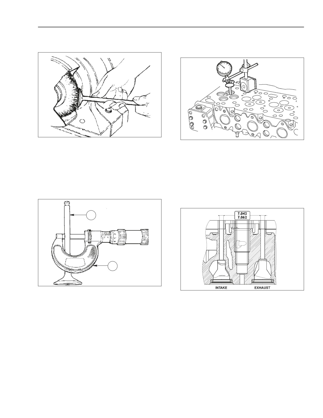
Remove the carbon deposits from the valves by
Use a magnetic comparator (1) placed as shown.
means of a special metal brush.
Assembly play must be equal to 0.039 to 0.079 mm
Verify that the valves do not show traces of seizing,
(0.0015 to 0.0031 in.)
scoring or cracking.
Turn valve (2) and check that the centering error is
Reface if necessary the valve seats by grinding,
not exceeding 0.03 mm (0.0011 in.)
removing as little material as possible.
VALVE GUIDE
STEP 131
STEP 133
1
2
BS06K360
Figure 2-233
BS06K362
Figure 2-235
Use a micrometer (2) to measure valve stem (1),
Use a bore gauge to measure the valve guide inner
which must be equal to 6.97 to 6.99mm
diameter, which must be equal to 7.042 to 7.062 mm
(0.2744 to 0.2751 in.)
(0.2772 to 0.2780 in.)
87519804 NA
Issued 11-06
Bur
2-109
ENGINE REPAIR MANUAL
CHAPTER 2 - 667TA ENGINE OVERHAUL
VALVE SEATS
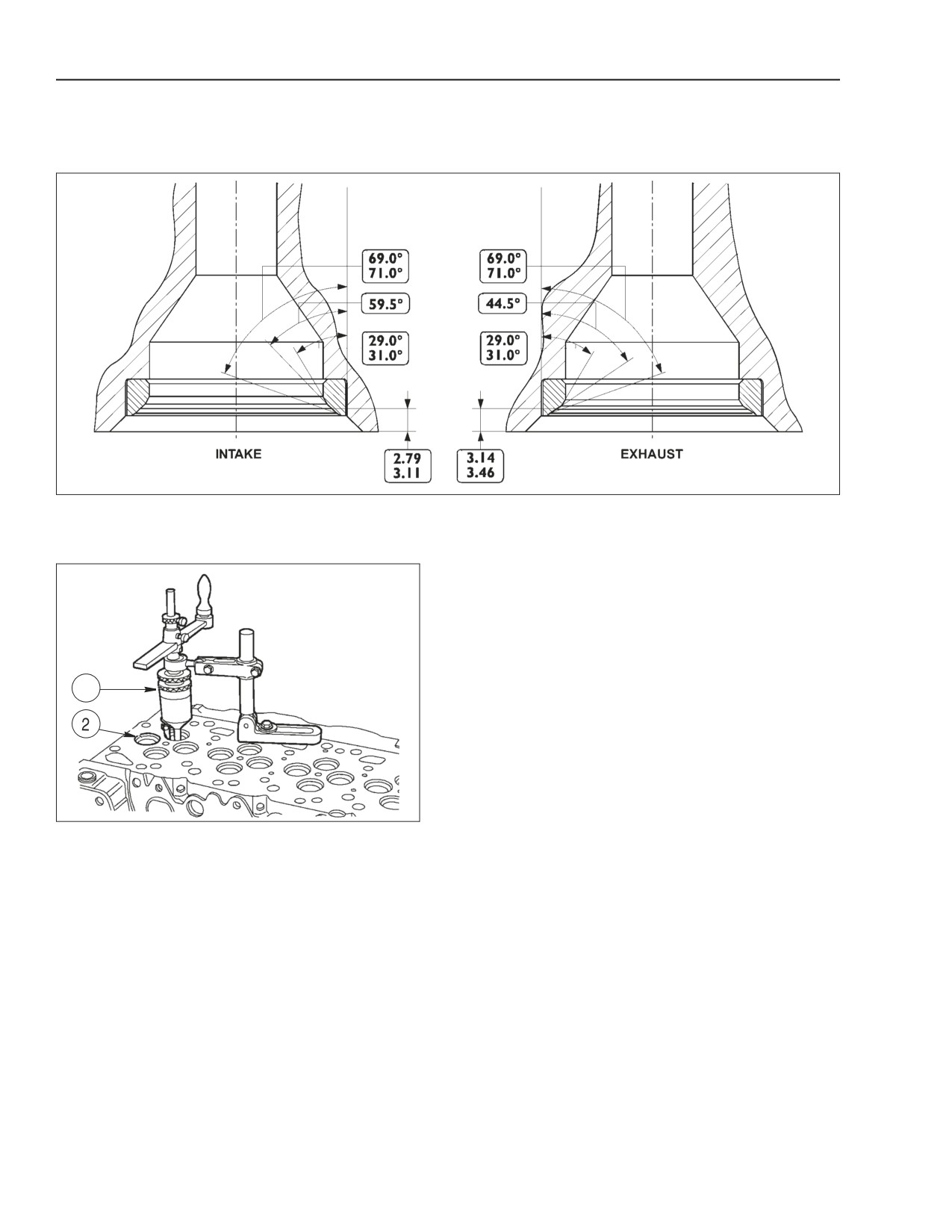
VALVE SEAT RECONDITIONING-REPLACEMENT
BS06K364
Figure 2-236
MAIN DATA ON VALVE SEATS ON CYLINDER HEAD
STEP 134
1
BS06K363
Figure 2-237
Check valve seats (2) if slight scoring or burrs are
found, regrind seats with tool (1) according to the
angle values shown in figure 2-236 above.
2-110
Issued 11-06
Bur
87519804 NA
ENGINE REPAIR MANUAL
CHAPTER 2 - 667TA ENGINE OVERHAUL
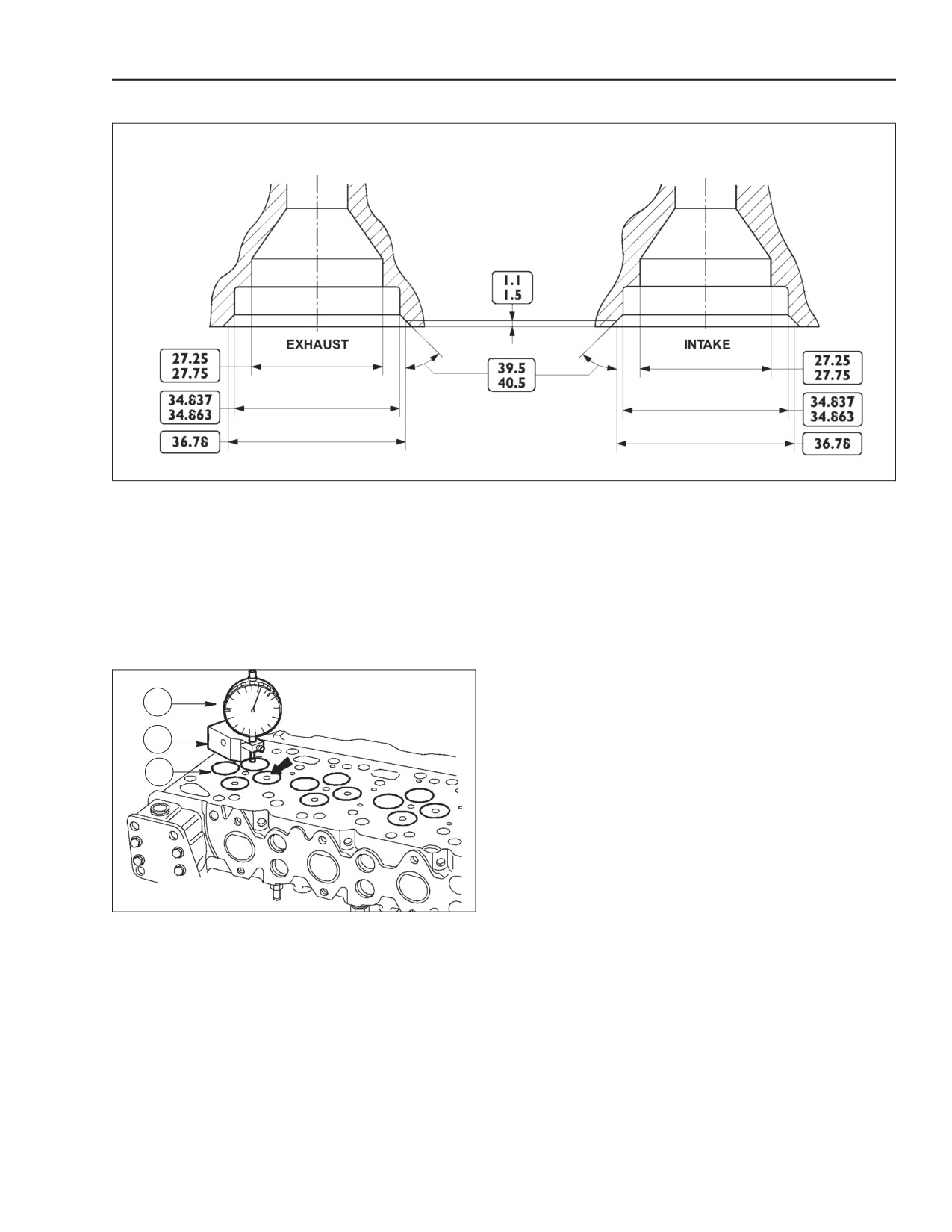
STEP 135
BS06K365
Figure 2-238
MAIN DATA ON VALVE SEATS
If the valve seats cannot be reseated, just by
Heat the cylinder head to 80° to 100° C
grinding, replace them with replacement parts. By
(176° to 212° F) and using the proper beater, install
using tool (1, in step 134) to remove as much
the new valve seats (previously cooled) into the
material as possible from the valve seats (taking care
heated cylinder head.
not to damage the cylinder head) until they can be
Recondition the valve seats with tool (1 in step 134)
extracted from the cylinder head using a punch.
according to the values shown in figure 2-238 above.
STEP 136
1
2
3
BS06K366
Figure 2-239
After the reconditioning operations, verify by means
of base (2) and dial indicator (1), that valve hollow (3)
corresponds to the specified value.
87519804 NA
Issued 11-06
Bur
2-111
ENGINE REPAIR MANUAL
CHAPTER 2 - 667TA ENGINE OVERHAUL
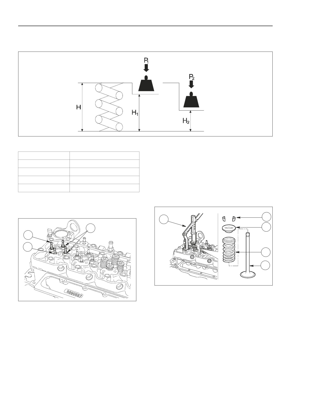
VALVE SPRINGS
STEP 137
BS06K367
Figure 2-240
MAIN DATA FOR INTAKE AND EXHAUST VALVE SPRING CHECK
Height
Under a load of
mm
N
H
47.75
Free
H1
35.33
P
339.8 ± 9 N
H2
25.20
P2
741 ± 39 N
CYLINDER HEAD
STEP 139
STEP 138
2
1
3
3
1
2
4
5
BS06K369
Figure 2-242
Position spring (4) and upper collar (3) on the
cylinder head. Use tool (1) to compress spring (4)
Figure 2-241
and lock the parts to the valve by means of lock
Lubricate the valve stem (1) and insert into the
cones (2).
respective valve guide according to the position
marked when disassembling.
Install seal rings (2 and 3) into the valve guide.
IMPORTANT: Seal rings (2) for intake valves are
yellow. Seal rings (3) for exhaust valves are green.
2-112
Issued 11-06
Bur
87519804 NA
ENGINE REPAIR MANUAL
CHAPTER 2 - 667TA ENGINE OVERHAUL
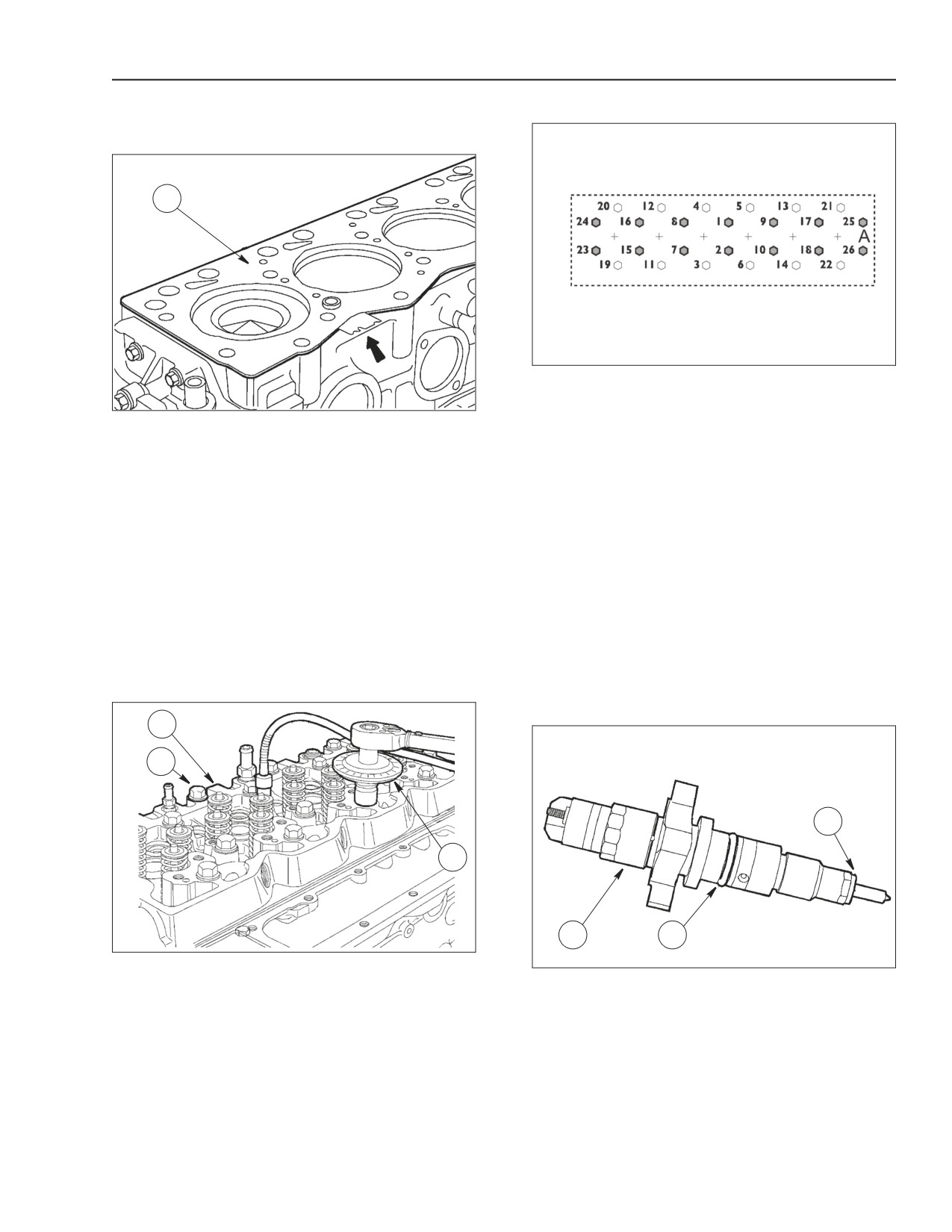
INSTALLING THE CYLINDER HEAD
STEP 142
STEP 140
1
BS06K372
Figure 2-245
1. NON SHADED BOLTS-
12X1.75X130 MM
BS06K370
Figure 2-243
2. SHADED BOLTS-
12X1.75X150 MM
Verify that the cylinder head and the engine block
Cylinder head fastening bolt tightening sequence:
mating surfaces are both clean.
•
1st phase: Pre-fastening by means of torque
Take care not to damage the cylinder head gasket.
wrench.
Set the cylinder head gasket (1) with the writing
Bolt 12x1.75x130 mm- (1)-
30 - 40 Nm
"TOP" (1) facing the head.
(22 - 30 lbf ft.)
The arrow shows the point where the gasket
Bolt 12x1.75x150 mm- (2)-
50 - 60 Nm
thickness is given.
(37 - 44 lbf ft.)
IMPORTANT: Prior to reusing the cylinder head
•
2nd phase: Angle tightening: 90° ± 5°- with tool (3)
fastening bolts, verify that they do not show traces of
•
3rd phase: Angle tightening: 90° ± 5°- with tool (3)
wear, deformations or corrosion. If they do replace
A= Front side
them.
INSTALLING INJECTORS
STEP 141
STEP 143
1
2
3
3
1
2
BS06K371
Figure 2-244
BS06K373
Figure 2-246
Install cylinder head (1), attach bolts (2) and tighten
them in three successive steps according to the
Install a new sealing ring (2) lubricated with vaseline
procedure in the following figure (step 142).
and a new sealing washer (3) on injector (1).
87519804 NA
Issued 11-06
Bur
2-113
ENGINE REPAIR MANUAL
CHAPTER 2 - 667TA ENGINE OVERHAUL
STEP 144
STEP 146
1
1
4
2
5
2
3
3
BS06K374
Figure 2-247
BS06K376
Figure 2-249
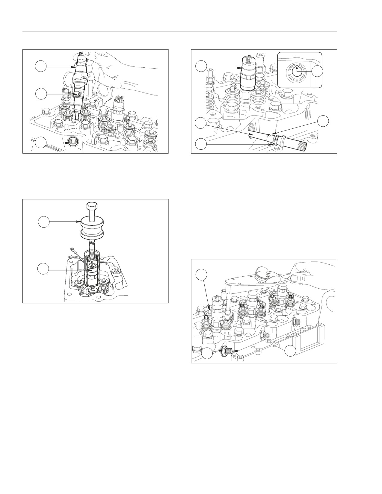
Install injectors (1) on the cylinder head seats,
Install a new sealing ring (3) lubricated with vaseline
directed so that the fuel inlet hole (2) is facing the fuel
on the fuel manifold (2) and install it into the cylinder
manifold seat (3) side
head seat so that the positioning ball (5) is lined up
with the notch in the housing (4).
STEP 145
IMPORTANT: Disassembled fuel manifolds (2) must
not be reused, they need to be replaced with new
ones.
1
IMPORTANT: During this operation, the injector (1)
shall be moved so that the manifold (2) is properly
inserted into the fuel inlet hole.
STEP 147
2
1
BS06K375
Figure 2-248
Use Special Tool 380001099 (1) to install the injector
(2) into its seat.
Screw injector fastening bolts without tightening
them.
3
2
BS06K377
Figure 2-250
Use a torque wrench to tighten gradually and
alternating the injector fastening bolts (1) to
7.7 - 9.3 Nm (5.7 - 6.9 lbf ft.).
Screw the fastening nuts (2) on the fuel manifold (3)
without locking them.
Tighten the fuel manifold (3) fastening nuts (2) to
50 Nm (36.9 lbf ft.) of torque.
2-114
Issued 11-06
Bur
87519804 NA
ENGINE REPAIR MANUAL
CHAPTER 2 - 667TA ENGINE OVERHAUL
RODS AND TAPPETS
STEP 149
STEP 148
BS06K380
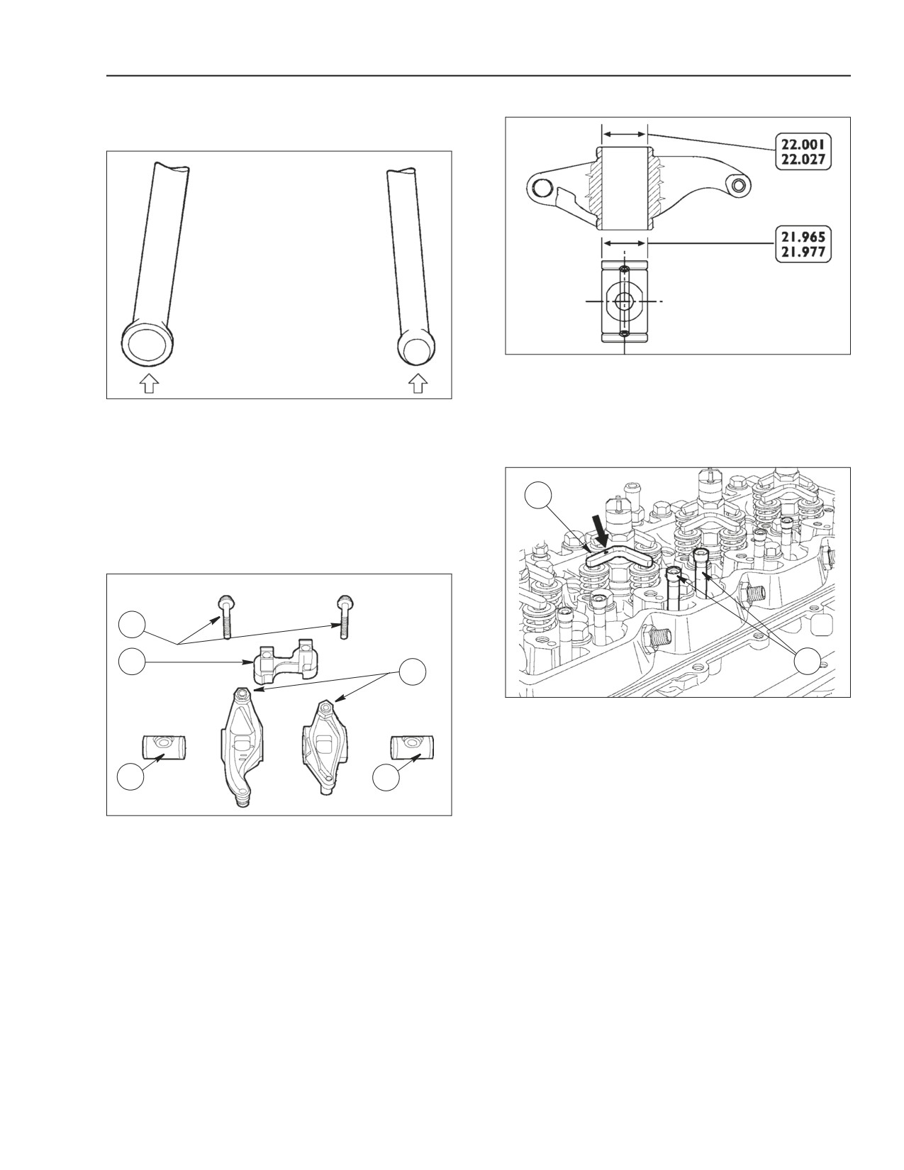
Figure 2-253
MAIN DATA OF ARBOR-ROCKER ARM
BS06K378
Figure 2-251
Check that shaft/rocker coupling surfaces are not
showing excessive wear or any damage.
Rocker control rods should not be distorted. The ball
seats in touch with the rocker adjusting bolt and with
STEP 150
tappets (arrows) should not show any signs of
seizing or wear, otherwise replace them. Intake and
exhaust valve control rods are identical and therefore
1
interchangeable.
ROCKER ARM ASSEMBLY
1
2
2
4
BS06K381
Figure 2-254
Install the rods (2).
Position jumpers (1) on valves with marks (→) facing
the exhaust manifold.
3
3
BS06K379
Figure 2-252
PARTS MAKING UP THE ROCKER ARM ASSEMBLY
1. BOLTS
2. SUPPORT
3. ARBOR
4. ROCKER ARM
87519804 NA
Issued 11-06
Bur
2-115
ENGINE REPAIR MANUAL
CHAPTER 2 - 667TA ENGINE OVERHAUL
STEP 151
STEP 153
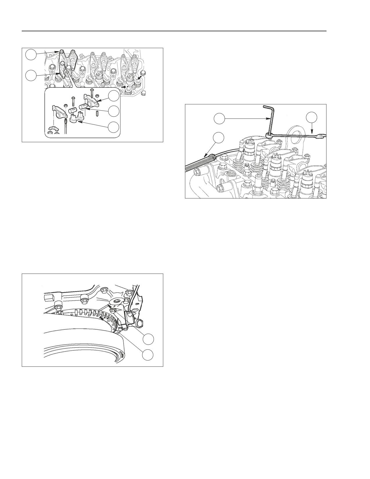
Measure the circumference of the tone wheel and
1
divide by 3. Starting from the reference mark on tone
wheel put on in step 152. Put the other two marks of
the calculated length on the tone wheel.
2
VALVE CLEARANCE ADJUSTMENT
3
STEP 154
4
1
3
5
2
BS06K382
Figure 2-255
Check tappet adjusters (1) that they are loose to
prevent their balking on the rods (2, figure 2-254)
when installing the rocker assembly.
Then install the rocker assembly consisting of:
bracket (5), rockers (3), shafts (4), and secure them
to the cylinder head by tightening the fastening bolts
(2) to 36 Nm (26.5 lbf ft.) of specified torque.
BS06K383
Figure 2-257
Adjust clearance between rockers and valves using
LOCATING TOP DEAD CENTER (TDC)
set screw wrench (1), box wrench (3) and feeler
gauge (2).
IMPORTANT: Due to the additional lobe for the
Internal EGR, each cylinder must cylinder must be
Working clearance shall be as follows:
adjusted by taking it to the T.D.C. (top dead center)
• Intake valves: 0.20 - 0.30 mm (0.008 - 0.012 in.)
and adjusting the clearance of both valves on every
• Exhaust valves: 0.46 - 0.56 mm (0.18 - 0.022 in.)
cylinder.
NOTE: Firing Order (1- 5- 3- 6- 2- 4)
STEP 152
•
Adjust the valves for cylinder number 1.
•
Rotate to the next reference mark and adjust valve
clearance for cylinder number 5.
•
Rotate to the next reference mark and adjust valve
clearance for cylinder number 3. This should be
one complete revolution of the tone wheel.
•
Rotate to the next reference mark and adjust valve
clearance for cylinder number 6.
1
•
Rotate to the next reference mark and adjust valve
clearance for cylinder number 2.
2
•
Rotate to the next reference mark and adjust valve
clearance for cylinder number
4. There should
BS06K345
Figure 2-256
have been two complete revolutions of the tone
wheel and all of the valves should be set.
1. ENGINE BLOCK
2. TONE WHEEL
•
Reinstall the number one injector.
• Remove the injector from the number one cylinder.
• Rotate engine over using Special Tool 380000988
to bring the number one cylinder to the highest
point using a dial indicator. Check to see if push
rods are loose, if they are not rotate the engine
360° now they should be loose.
• Put a reference mark on tone wheel (1) and the
engine block (2).
2-116
Issued 11-06
Bur
87519804 NA
ENGINE REPAIR MANUAL
CHAPTER 2 - 667TA ENGINE OVERHAUL
STEP 155
STEP 156
1
3
2
4
3
5
4
1
5
2
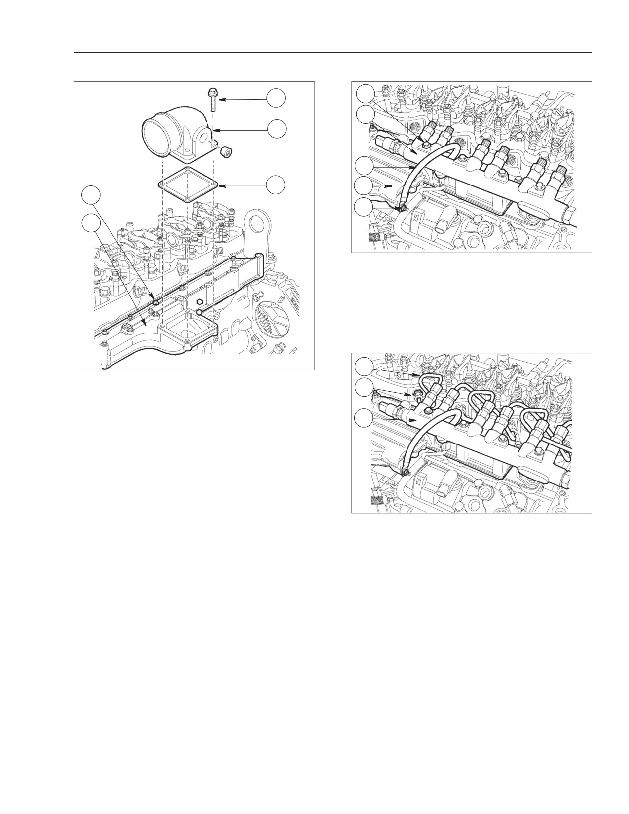
BS06K385
Figure 2-259
Install the rail (2) and tighten the bolts (1) to the
general bolt torque specifications in the repair
manual. Connect the ground cable (3) to the intake
manifold (4) and tighten the fastening nut (5) to 20 to
30 Nm (14.8 to 22.1 lb.- ft.) the specified torque.
STEP 157
1
BS06K384
Figure 2-258
Apply Loctite 5999 to the contact surfaces of intake
2
manifold (1) and install the manifold and heater to the
cylinder head.
3
Screw in bolts (2) and tighten to 20 to 30 Nm (14.8 to
22.1 lb.- ft.) the specified torque.
Install air intake (4) with a new gasket (5) and tighten
bolts (3) to the general bolt torque specifications in
the repair manual.
The figure shows the air intake for 667TA/EEG -
667TA/EEC engines.
BS06K386
Figure 2-260
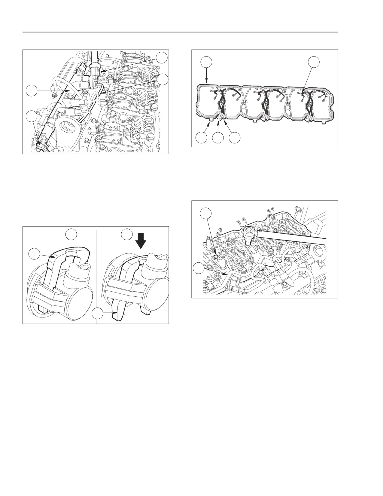
Connect new fuel lines (1) to rail (3) and injector
manifolds (2).
IMPORTANT: When ever fuel lines (1) are removed
they should always be replaced with new ones
87519804 NA
Issued 11-06
Bur
2-117
ENGINE REPAIR MANUAL
CHAPTER 2 - 667TA ENGINE OVERHAUL
STEP 158
STEP 160
3
1
5
4
1
2
2
3
4
BS06K389
Figure 2-263
BS06K387
Figure 2-261
Check wiring cable (5) condition, replace it if
Connect the fuel line (4) to rail (2) following the
damaged, by cutting the support (2) clamps and
procedure shown in the following figure (step 157).
removing the bolts (4) that secure it to connectors
(3). Install a new gasket (1) on the support (2).
IMPORTANT: Fuel line (4) connections shall be
tighten to 20 Nm (14.8 lb.-ft.) of torque, using the
STEP 161
proper box wrench and the torque wrench
380000158 (3).
1
STEP 159
A
B
1
2
BS06K390
Figure 2-264
Install the wiring support (2) and tighten the bolts (1)
1
to the general bolt torque specifications in the repair
manual.
BS06K388
Figure 2-262
Press the clamp (1) in arrow direction (Figure B) and
connect the line to the rail (2), figure 2-260), reset the
clamp to the initial locking position (Figure A).
IMPORTANT: Check for proper fuel line connection.
2-118
Issued 11-06
Bur
87519804 NA
ENGINE REPAIR MANUAL
CHAPTER 2 - 667TA ENGINE OVERHAUL
STEP 162
STEP 165
1
7
6
1
4
2
5
3
4
2
3
BS06K391
Figure 2-265
BS06K394
Figure 2-268
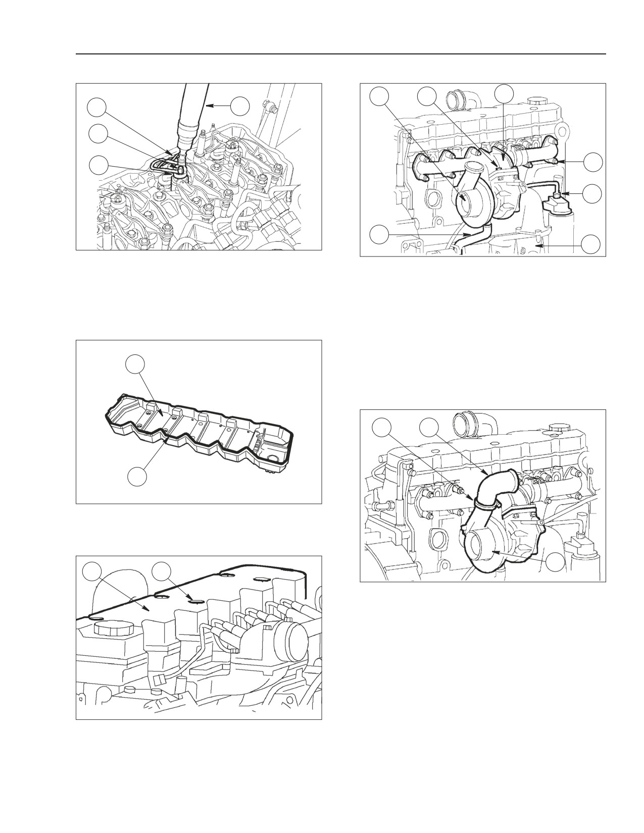
Connect the electrical cables (1) to the injectors (3)
Re-attach exhaust manifold (6) with new gaskets.
and use Special Tool 380000158 torque wrench (4)
Screw securing bolts (5) and tighten them to
to tighten the fastening nuts (2) to the general bolt
48 to 58 Nm (35.4 to 42.8 lb.-ft.) the specified torque.
torque specifications in the repair manual.
Re-attach turbo-charger (1) to exhaust collector (6)
STEP 163
with a new gasket and tighten securing nuts (7) to
20 to 30 Nm (14.8 to 22.1 lb.-ft.) the specified torque.
Connect line (2) to turbo-charger (1) support (3).
1
Connect oil line (4) to heat exchanger support.
STEP 166
1
2
2
BS06K392
Figure 2-266
Install a new gasket (2) on the tappet cover (1).
STEP 164
3
1
2
BS06K395
Figure 2-269
Connect the air duct (2) to the turbo-charger (3) and
lock it with clamp (1).
BS06K393
Figure 2-267
Install the tappet cover (1) and tighten the nuts (2) to
20 to 30 Nm (14.8 to 22.1 lb.-ft.) the specified torque.
87519804 NA
Issued 11-06
Bur
2-119
ENGINE REPAIR MANUAL
CHAPTER 2 - 667TA ENGINE OVERHAUL
STEP 167
1
6
2
5
4
3
BS06K396
Figure 2-270
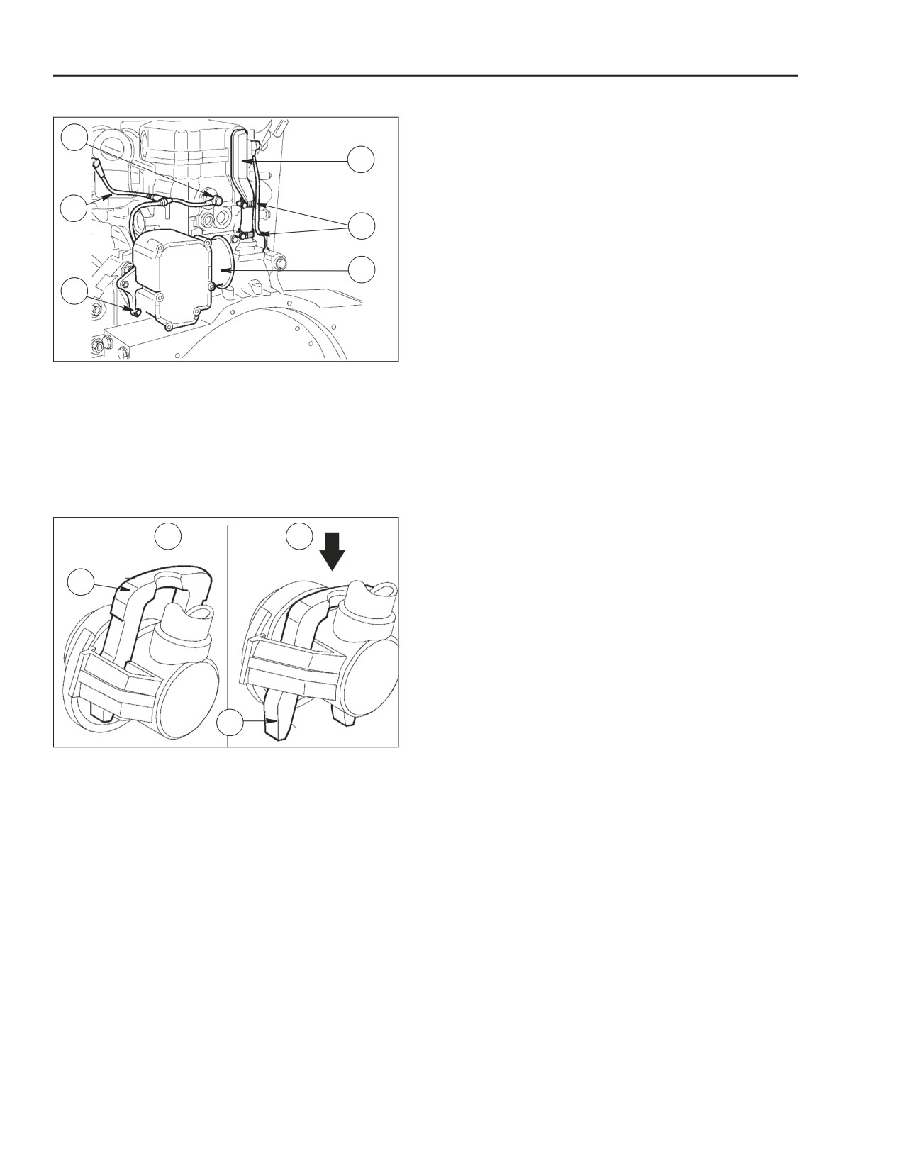
Insert the blow-by filter (4) tightening the bolts.
Connect the line (6) and attach the oil vapor recovery
line with clamp (5).
Connect the line (2) to the pressure-limiter device (1)
by the figure below (step 166).
STEP 168
A
B
1
1
BS06K388
Figure 2-271
Press the clamp (1) in arrow direction (Figure B) and
connect the line. Reset the clamp to the initial locking
position (Figure A).
IMPORTANT: Check for proper fuel line connection.
2-120
Issued 11-06
Bur
87519804 NA
ENGINE REPAIR MANUAL
CHAPTER 2 - 667TA ENGINE OVERHAUL
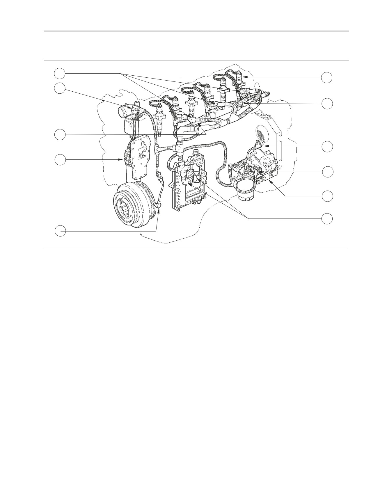
WIRING HARNESS CONNECTIONS TO ENGINE
STEP 169
1
6
2
7
3
8
4
9
10
11
5
BS06K398
Figure 2-272
9. FUEL HEATER AND TEMP
1. CONNECTIONS FOR ELECTRO-INJECTORS
5. CRANKSHAFT SENSOR
SENSOR
2. ENGINE COOLANT TEMPERATURE
6. ELECTRO-INJECTOR
10. HIGH PRESSURE REGULATOR
SENSOR
7. BOOST TEMPERATURE AND
3. COMMON RAIL FUEL PRESSURE SENSOR
11. EDC7UC31 CONTROL UNIT
PRESSURE SENSOR
4. OIL TEMPERATURE-PRESSURE SENSOR
8. CAMSHAFT SENSOR
Re-attach engine cable by connecting electro-
Apply rocker lever to engine lifting hooks, hook the
injectors (6) wiring connectors (1), air pressure/
rocker lever to a hoist and detach the engine from
temperature sensor (7), common rail pressure
rotating stand. Remove brackets.
sensor (3), EDC7UC31 electronic control unit (11),
high pressure pump sensor (10), camshaft sensor
(8), engine coolant temperature sensor on
thermostat (2), crankshaft sensor (5).
87519804 NA
Issued 11-06
Bur
2-121
ENGINE REPAIR MANUAL
CHAPTER 2 - 667TA ENGINE OVERHAUL
STEP 170
STEP 172
4
1
1
2
3
4
2
5
3
5
BS06K399
Figure 2-273
BS06K401
Figure 2-275
Complete engine installation as follows.
By hand screw on the fuel filter to the bracket (1).
From the right side:
Tighten the fuel filter 3/4 of a turn after the gasket
• Install the starter (5) to the flywheel housing (4)
makes contact with the bracket. Connect the fuel
and tighten the fastening nuts to 50 to 60 Nm (36.9
lines (2,3,4) to the relevant support connections (1)
to 44.3 lb.-ft.) the specified torque.
as shown in the following figure (step 171).
• Install the oil line (3) with a new sealing ring into
STEP 173
the engine block and secure it to the turbo-charger
(1) by the bolts (2) and tighten to 20 to 30 Nm
A
B
(14.8 to 22.1 lb.-ft.) the specified torque.
STEP 171
1
1
2
1
BS06K388
Figure 2-276
3
Press the clamp (1) as shown in (figure B).
After connecting the line reset the clamp (1) to the
initial locking position (A), to prevent deformations.
BS06K400
Figure 2-274
NOTE: when installation is complete, fill engine with
Install the bracket (2) including the fuel filter bracket
the proper lubricating oil.
(1) to the engine block, tighten the bolts (3) to the
general bolt torque specifications in the repair
manual.
2-122
Issued 11-06
Bur
87519804 NA
ENGINE REPAIR MANUAL
CHAPTER 3
667TA
TIER III
CHARGING AND START-UP
Issued 11-2006
Book/Form Number 87519804 NA
Copyright © 2006. .
Printed in U.S.A. • Bur
Source Code No. unknown

ENGINE REPAIR MANUAL
CHAPTER 3 - CHARGING AND START-UP
CNH America LLC reserves the right to make improvements in design or changes in specifications at any time without incurring any
obligation to install them on units previously sold.
All data given in this publication is subject to production variations. Dimensions and weights are only approximate. Illustrations do
not necessarily show products in standard condition. For exact information about any particular product, please consult your Dealer
Revision History
Issue
Issue Date
Applicable Machines
Remarks
667TA/EEG 667TA/EEC 667TA/EBF
First Edition
11-2006
87519804 NA
667TA/EED 667TA/EBJ 667TA/EDJ
3-II
Issued 11-06
Bur
87519804 NA
ENGINE REPAIR MANUAL
CHAPTER 3
CHARGING AND START-UP
TABLE OF CONTENTS
STARTER MOTOR
3-3
Quick Diagnosis
3-3
BOSCH 24 Volt - 4 KW Starter
3-4
ISKRA 24 Volt - 4 KW Starter
3-5
DENSO 24Volt - 7.8KW Starter
3-5
ALTERNATOR
3-6
Quick Diagnosis
3-6
BOSCH: NCBI 28 Volt 35-70 Amp
3-7
87519804 NA
Issued 11-06
Bur
3-1
ENGINE REPAIR MANUAL
CHAPTER 3 - CHARGING AND START-UP
STARTER MOTOR
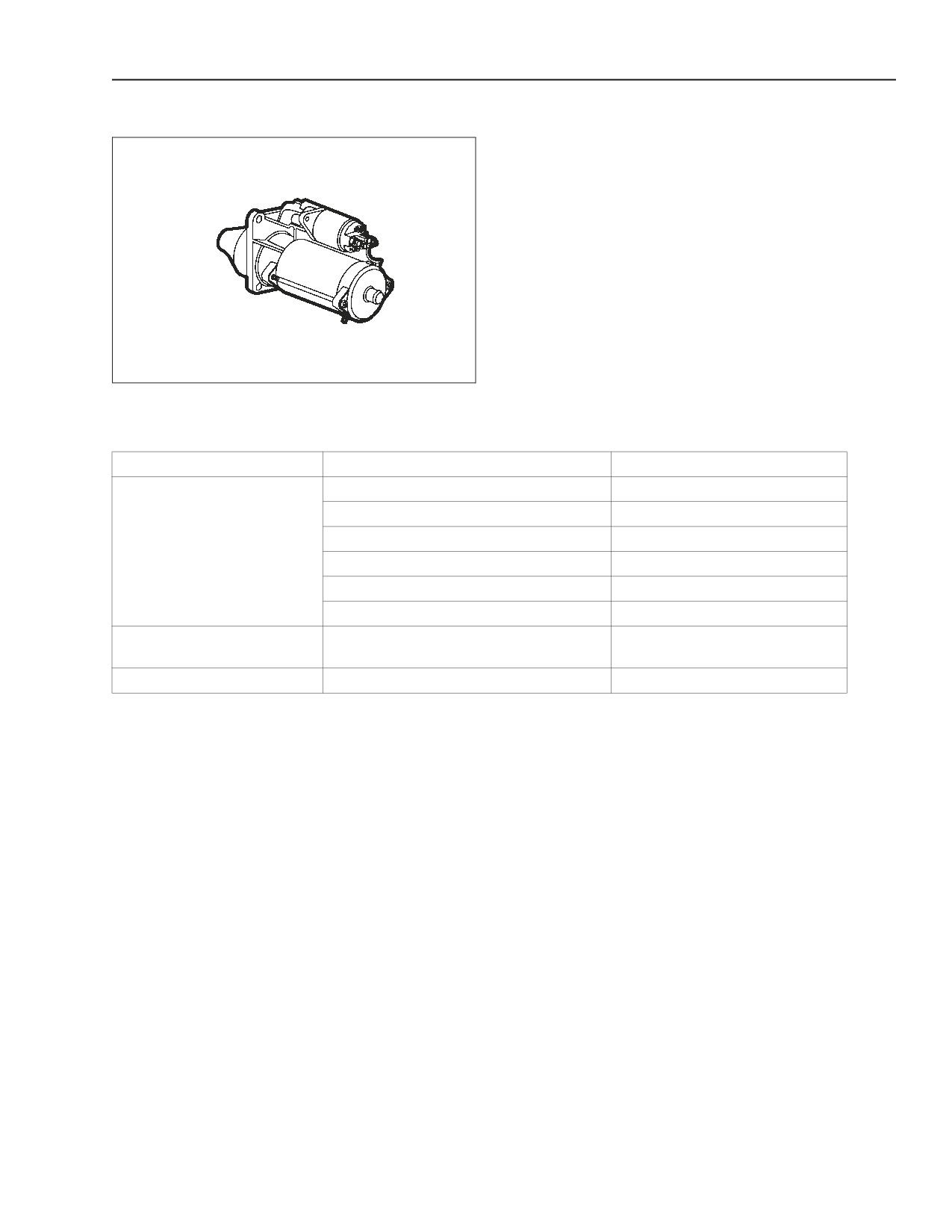
Manufacture- BOSCH - 24 Volt - 4kW
For Engines:
667TA/EEG
667TA/EEC
Manufacture- ISKRA - 24 Volt - 4kW
For Engines:
667TA/EBF
667TA/EED
Manufacture- Denso - 24 Volt - 7.8kW
For Engine:
667TA/EDJ
BS06K403
Figure 3-1
QUICK DIAGNOSIS
Fault
Possible Causes
Remedy
1.- Batteries run down
Recharge or Replace
2.- Circuit connections oxidized or loose
Replace the component
3.- Brushes damaged or worn
Replace the component
Dragging torque insufficient
4.- Short-circuit in field windings
Replace the component
5.-Open or short circuit in armature
Replace the component
6.- Out of round bushings
Replace the component
Dragging torque sufficient, but
Free wheel or faulty electro-magnet
Replace the component
the engine won’t start
Pinion won’t engage
Bevelled ring gear
Restore
87519804 NA
Issued 11-06
Bur
3-3
ENGINE REPAIR MANUAL
CHAPTER 3 - CHARGING AND START-UP
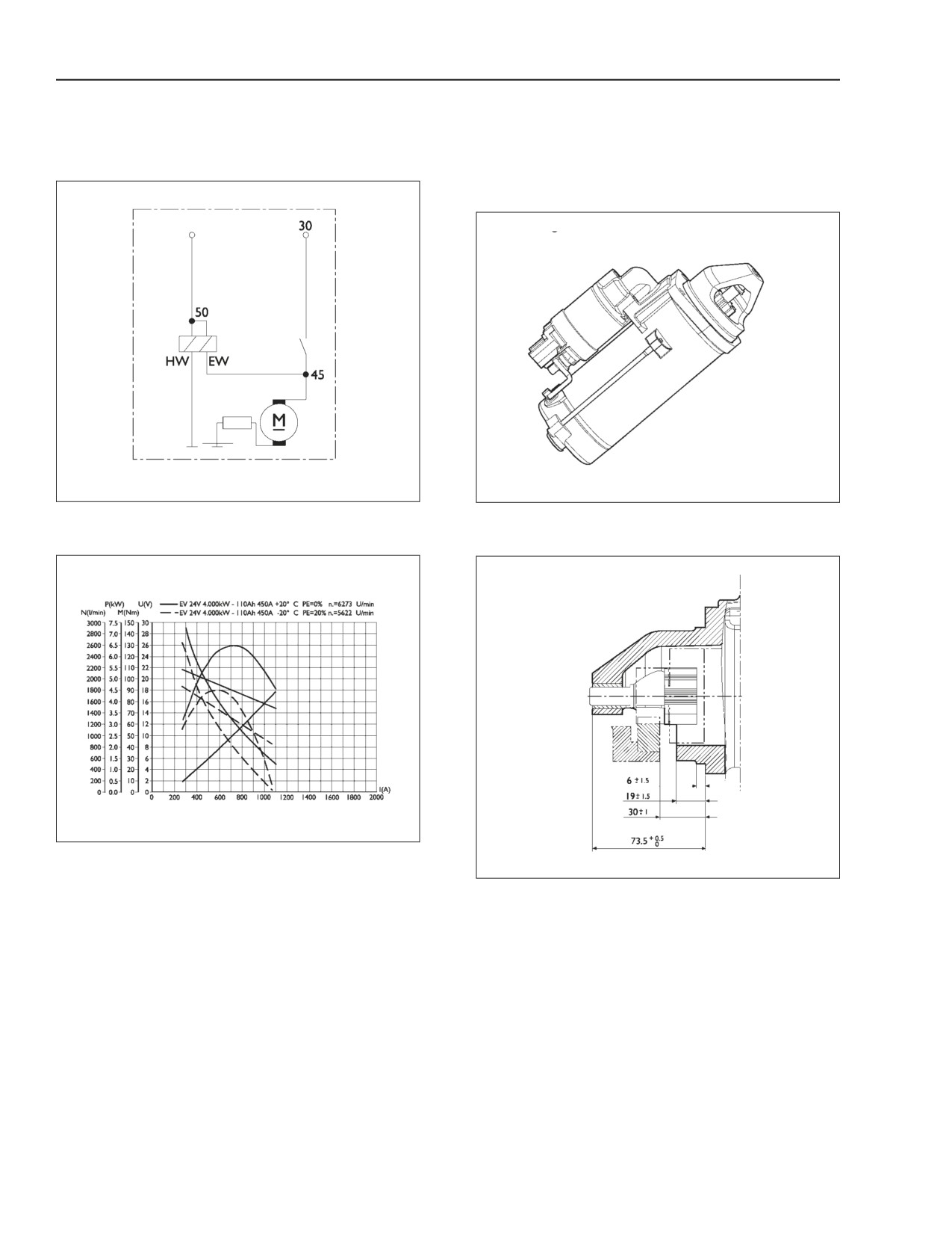
BOSCH 24 VOLT - 4 KW STARTER
6- pole type with series excitation and engagement
Clockwise direction of rotation
by means of a fork controlled by an electromagnet.
Rated voltage- 24 volts
Power- 4 kW
BS06K404
Figure 3-2
BS06K406
Figure 3-4
WIRING DIAGRAM
3/4/ VIEW
BS06K405
Figure 3-3
CHARACTERISTIC CURVES
BS06K407
Figure 3-5
PINION ADJUSTER
3-4
Issued 11-06
Bur
87519804 NA
ENGINE REPAIR MANUAL
CHAPTER 3 - CHARGING AND START-UP
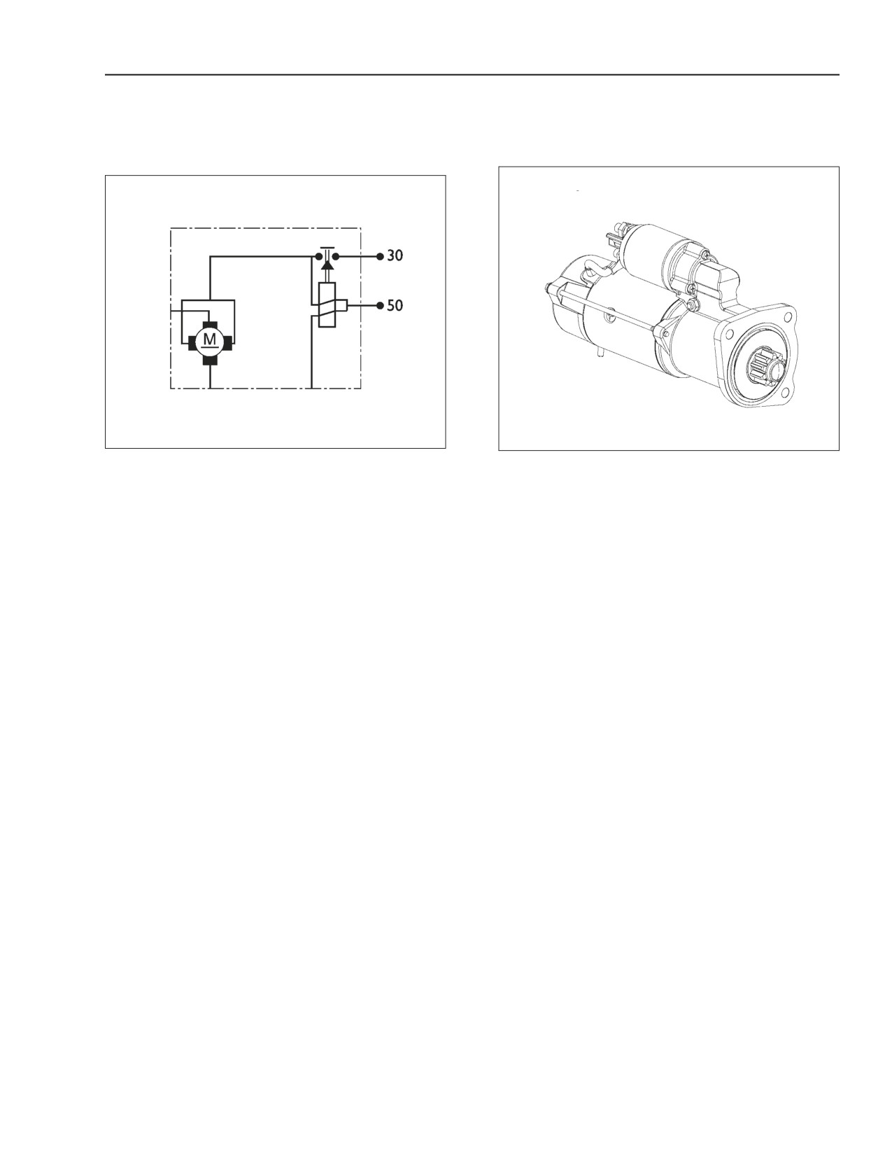
ISKRA 24 VOLT - 4 KW STARTER
Rated voltage- 24 volts
Fork mesh type, driven by an electromagnet.
Power- 4kW
Clockwise direction of rotation
BS06K408
Figure 3-6
BS06K409
Figure 3-7
WIRING DIAGRAM
3/4 VIEW
DENSO 24VOLT - 7.8KW STARTER
There is no information at time of print on this starter.
Used on the 667TA/EDJ engine.
87519804 NA
Issued 11-06
Bur
3-5
ENGINE REPAIR MANUAL
CHAPTER 3 - CHARGING AND START-UP
ALTERNATOR
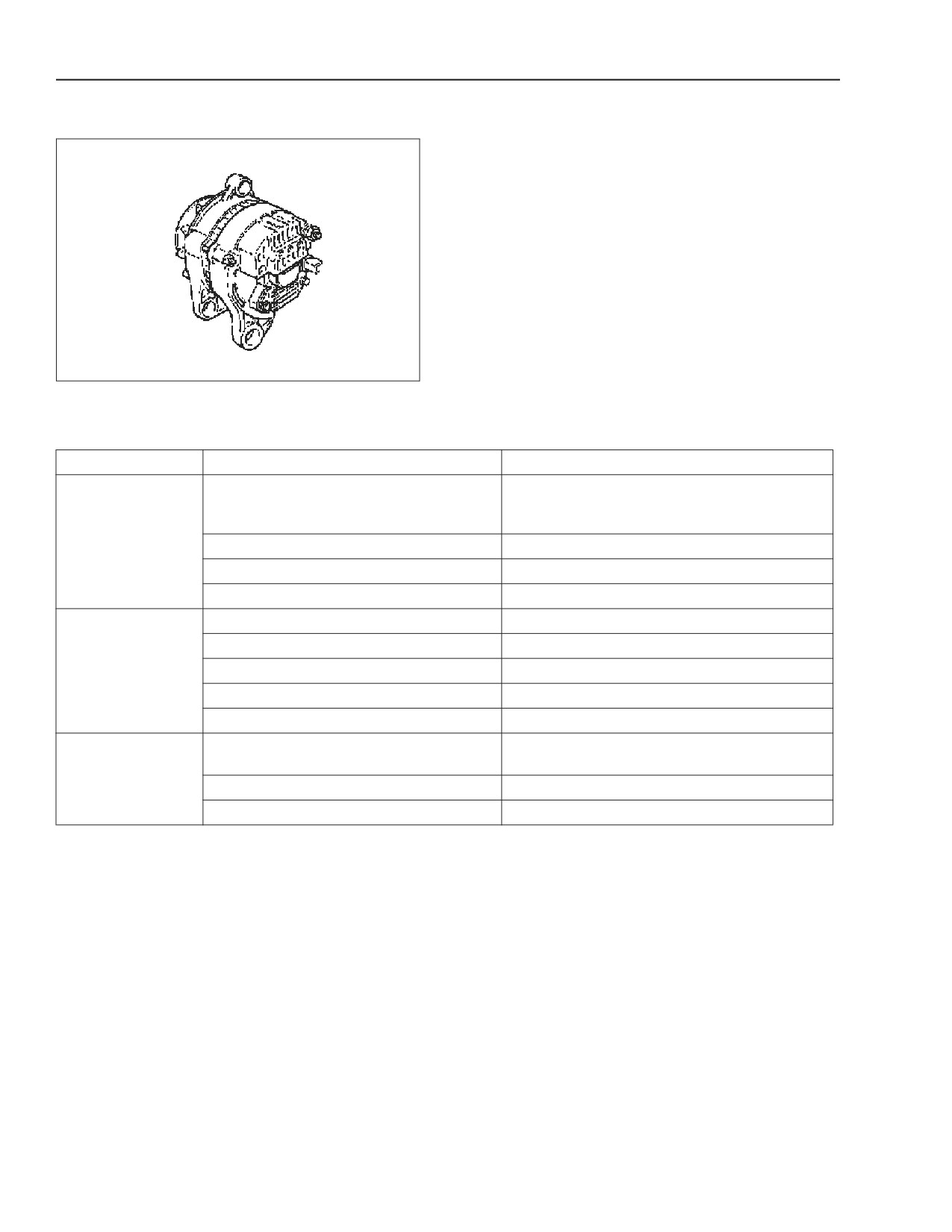
Manufacture - BOSCH
Part number- NCBI 28 V 35-70 A
For engines:
667TA/EEG
667TA/EEC
667TA/EDJ
BS06K410
Figure 3-8
QUICK DIAGNOSIS
Fault
Possible causes
Remedy
Check the recharge circuit connections. Clean and
1. Open in recharge circuit (warning light,
tighten the cable terminals on the alternator and
fuse, connector, etc.)
battery.
No recharge
2. Voltage regulator not working
Replace the component
3. Open rotor winding
Replace the component
4. Worn brushes
Replace the component
1. Loose belt
Check automatic belt tensioner
2. Faulty voltage regulator
Replace the component
Poor recharge
3. Excessive wear of rotor rings or brushes
Replace the component
4. Short-circuited diodes
Replace the component
5. Short-circuited rotor windings
Replace the component
Check the connections to terminals and cable
1. Loose circuit connections
terminals of batteries, starter motor and alternator
Excessive recharge
2. Voltage regulator not working
3. Faulty ground
Check ground connections
3-6
Issued 11-06
Bur
87519804 NA
ENGINE REPAIR MANUAL
CHAPTER 3 - CHARGING AND START-UP
BOSCH: NCBI 28 VOLT 35-70 AMP
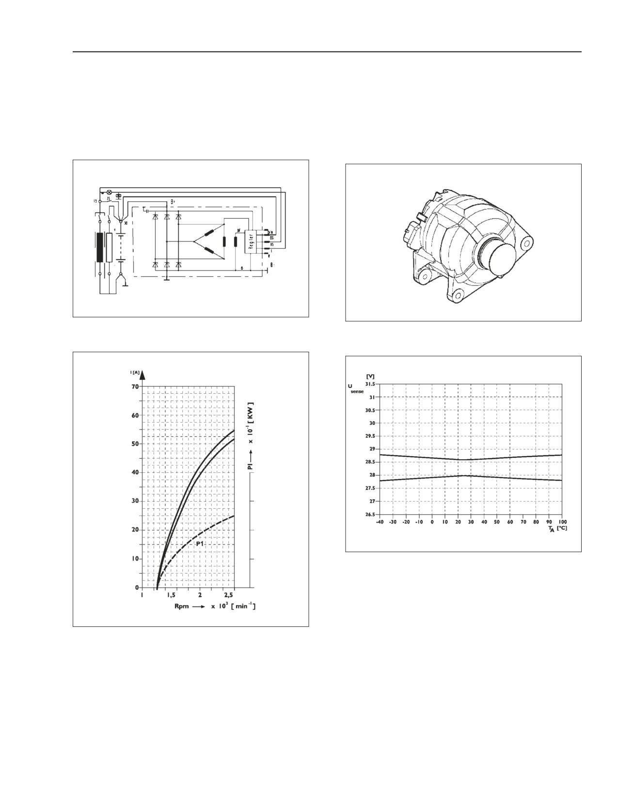
Three-phase type, claw-type rotor, 11 diode rectifer
Direction of rotation- (control side) clockwise
and electronic voltage regulator.
Current delivered at 6.000 min-1 >= 55 amps
Rated voltage- 28.5 volts
BS06K411
Figure 3-9
BS06K413
Figure 3-11
WIRING DIAGRAM
3/4 VIEW
BS06K414
Figure 3-12
CHARACTERISTIC CURVES OF VOLTAGE REGULATOR
BS06K412
Figure 3-10
CHARACTERISTIC CURVES OF CURRENT DELIVERY
87519804 NA
Issued 11-06
Bur
3-7