UPRIGHT REFRIGERATED DISPLAY UNITS. Manual in 7 languages (2019) - page 3
INDEX
MACHINE DESCRIPTION
2
IDENTIFICATION TAG
2
GENERAL NOTES BY THE DELIVERY
2
SAFETY PRESCRIPTION
3
INSTALLATION
4
TECHNICAL SPECIFICATIONS
8
CONTROL PANNELS
9
TEMPERATURE SETPOINT SETTING/VARIATION
10
SMART FUNCTIONS - Quick-access functions
10
BLOCKIEREN DER TASTATUR
10
MANUAL PROBE READING PRINTOUT
11
PARAMETER CONFIGURATION
11
USER PARAMETER CONFIGURATION - PROBE READING
16
DEFAULT PARAMETER RECOVERY
16
ALARMS
16
DEFROST
20
STOPPING
20
WORKING IRREGULARITIES
20
DAILY CLEANING
21
GENERAL CLEANING AND MAINTENANCE
21
USEFULL ADVICES FOR THE CARE OF THE STAINLESS STEEL
22
USAGE INTERRUPTIONS
22
MALFUNCTIONING
22
WASTE DISPOSAL AND DEMOLITION
23
REFRIGERANT MATERIAL SAFETY DATA SHEET
23
1
MACHINE DESCRIPTION
This device has been designed for temporary exposition and conservation of food products. Any other use is
to be considered improper.
ATTENTION: the appliances are not suitable for installation outdoors or in environments subject to the
action of the elements.
The manufacturer cannot be held liable for improper use of its products.
The units are equipped with a finned evaporator protected against oxidation, a hermetic compressor, a
copper aluminium condenser and a digital electronic data card. The unit is equipped with removable shelves,
except for the Gelateria -25°/-15° C, model in which they are fixed.
An HFC refrigerant fluid, approved by current legislation, is used in the refrigerating units.
IDENTIFICATION TAG
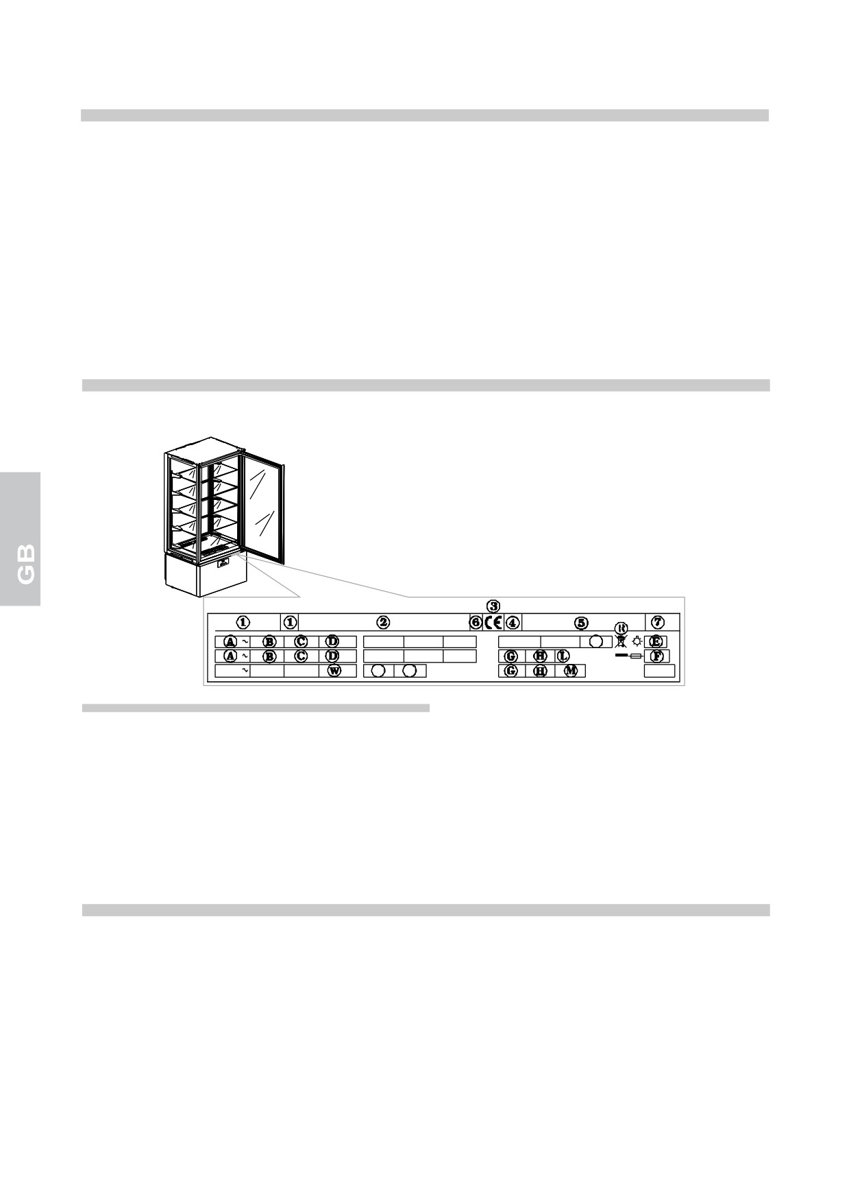
For any communication with the manufacturer, always mention the MODEL and the SERIAL NUMBER of
the appliance which are reported on the technical feature plate.
Z
Y
Z
Refrigerator rating plate containing the following ratings
1) MODEL
D) RATED POWER
2) SUPPLIER’S NAME AND ADDRESS
E) TOTAL LAMP POWER
3) CE MARK
F) FAUSE CURRENT
4) YEAR OF MAKE
G) REFRIGERATING SYSTEM TEMPERATURE
5) SERIAL NO
GRADE
6) ELECTRIC INSULATING GRADE
H) REFRIGERATING GAS QUANTITY
7) ELECTRIC PROTECTION GRADE
L) REFRIGERATING GAS
A) POWER SUPPLY VOLTAGE
R) WEEE SYMBOL
B) ELECTRIC CURRENT RATE
W) HEATING SECTION POWER
C) POWER SUPPLY FREQUENCY
GENERAL NOTES BY THE DELIVERY
At the delivery inspect that the packing is not injured and that it has not been damaged during the transport.
After having unpacked the unit check and verify that all of the parts and components have been included and
that its characteristics and condition correspond to the specifics of the order that you made.
Otherwise contact immediately the retailer.
While complementing you on your excellent choice we hope that you will be able to fully utilise our
equipment following the necessary directions and precautions contained in this manual.
But, remenber that any reproduction of this manual is forbidden and that due to a constant pursuit of
innovation and technological quality, the features hereby presented could change without notice.
2
SAFETY PRESCRIPTIONS
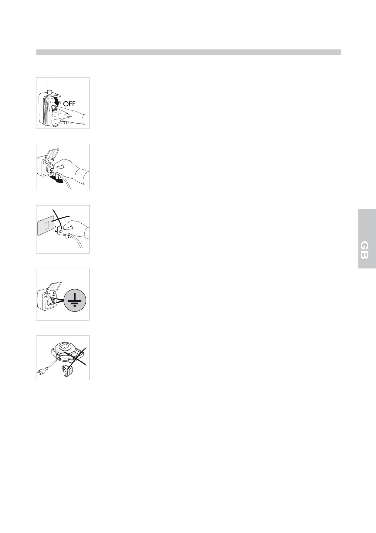
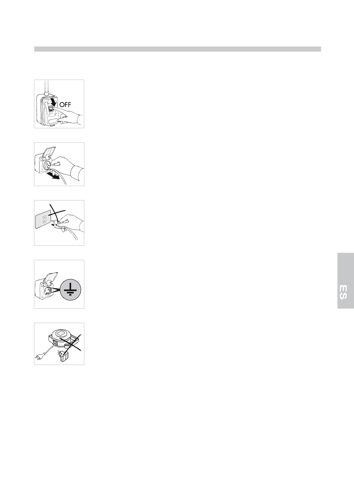
WARNING: before any maintenance or cleaning operation the machine must be insulated from the current:
- witch the general cut-out in OFF position;
- remove the plug;
WARNING: do not use current taps or plugs not provided with grounding.
The socket must be provided with GROUNDING.
WARNING: do not use adapters or patch cords for the connection to the electric line.
WARNING: wait the time necessary to reach the setted temperature before to introduce the food to preserve.
WARNING: do not put hot foods or drinks into the unit.
WARNING: see to the arrangement of the food products to be conserved inside in such a manner that they
do not extend beyond the shelves so as to not interrupt the flow of air inside the unit. Do not obstruct fan
intake area.
WARNING: do not carry out cleaning activities in the area around the unit with its door open.
Do not wash the appliance by spraying high-pressure water on the machine.
WARNING: not use chlorine based or otherwise toxic substances (bleach, muriatic acid, etc.) for cleaning
the unit or the areas directly adjacent to it.
Do not place any objects on the bottom of the unit. Use the proper shelves.
3
On the shelves the maximum distributed weight is not to exceed 12 kg.
WARNING: glass Breaking Hazard: Close or open the door VERY GENTLY AND NEVER ABRUPTLY OR
WITH VIOLENCE and do not lean on the door itself.
The cleaning and mantainance of the refrigerating engine and the compressor area needs the intervention of
a skilled technician, therefore it cannot be done by other persons.
For a maintenance intervention or in case of anomaly disconnect completely the machine; ask for the
TECHNICAL SERVICE to an entitled center and the use of original spare parts.
Failure to comply with what is written above may compromise the safety of the units.
INSTALLATION
The units are always shipped on pallets and protected by cardboard boxes.
On receiving and after having unpacked in case of dammages or missing pieces act as described in the
chapter "GENERAL NOTES BY THE DELIVERY".
All setting up and starting operations are to be carried out by skilled staff.
WARNING: package parts (plastic bags, polystyrene foam, nails and the like) are dangerous for children and
must not be left within their reach.
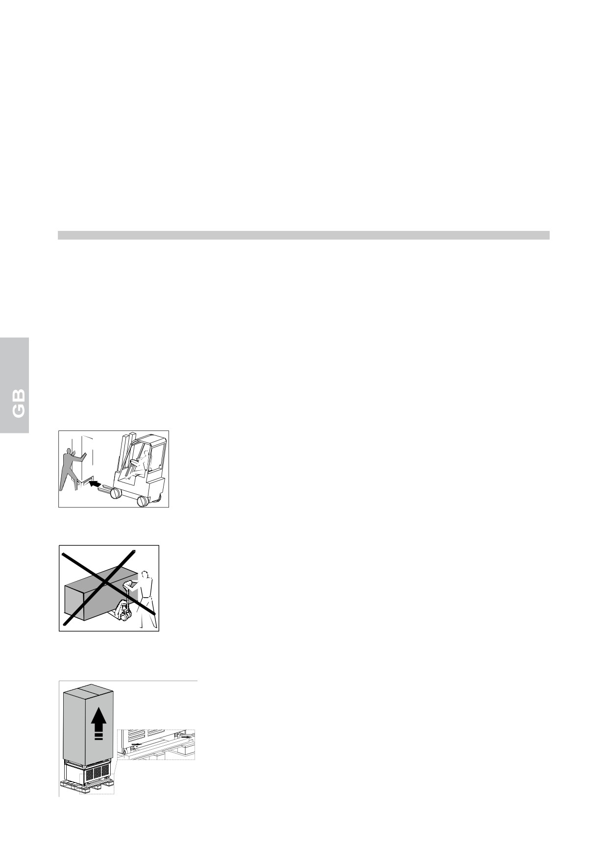
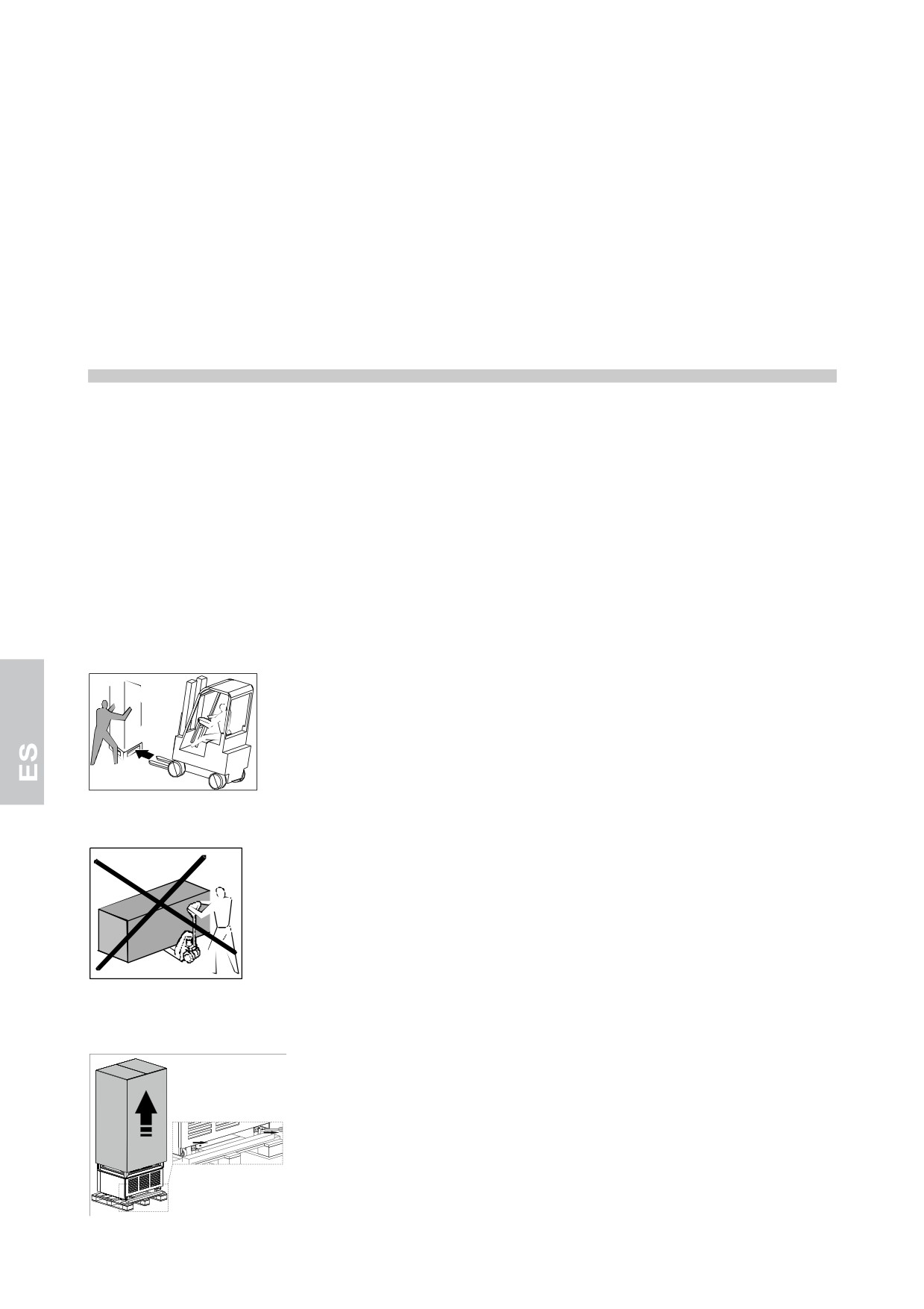
Lift the unit with a forklift and move it to its place of installation paying close attention that the load is well
balanced.
WARNING: overturning hazard: Never tilt the unit. During handling make sure that it is stabilised by qualified
personnel.
WARNING: never transport the unit in a horizontal position; such an operation could cause damage to the
structure and or to the operational plant.
Once at the installation site, follow the instructions below.
Remove the packing box, adhesive tape and any styrofoam pieces.
Remove the plate behind the appliance.
4
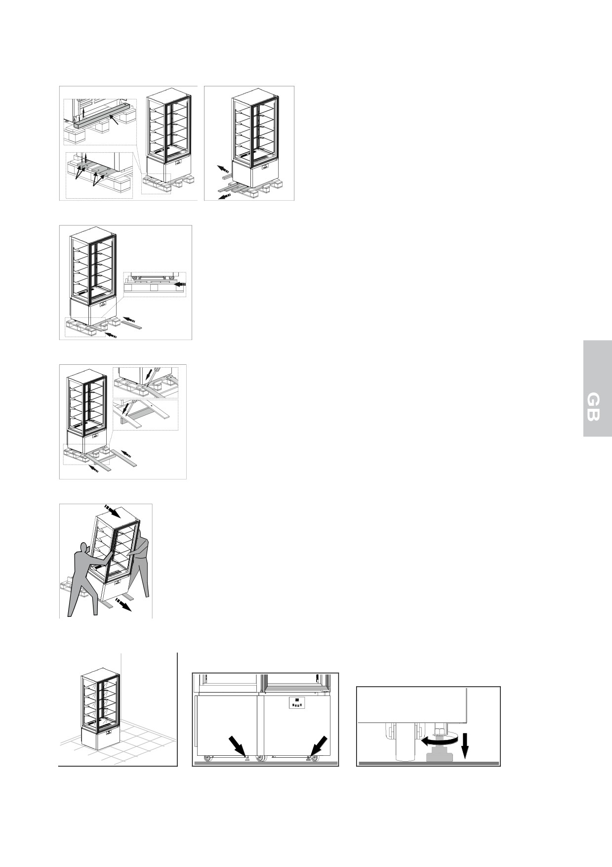
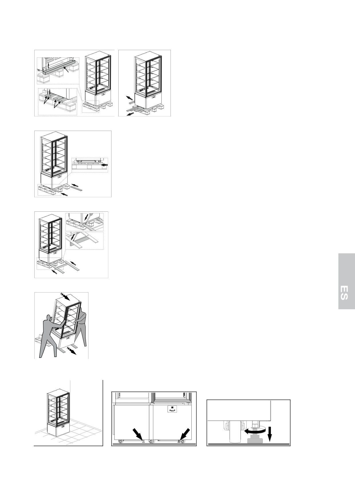
Pull out strips A, B and C located at the base of the package, removing the fixing screws first.
C
A
B
Insert the A strips under the wheels of the appliance.
A
A
Place the B and C strips in front of the package base and secure them.
B
C
C
B
Delicately slide the display window to the ground.
Place the unit in its permanent location.
Adjust the leveller feet found under the unit so that it does not shift or rock.
5
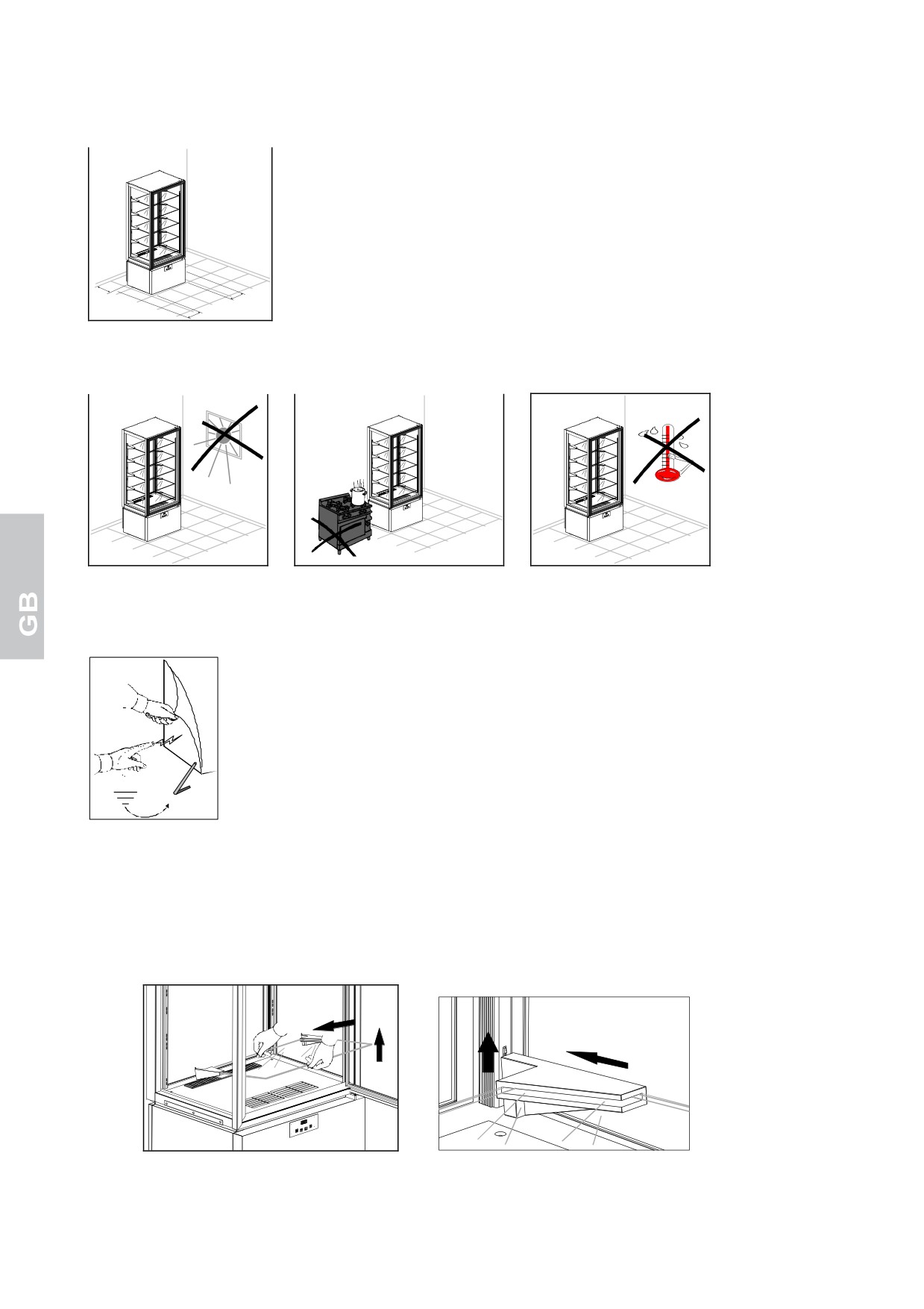
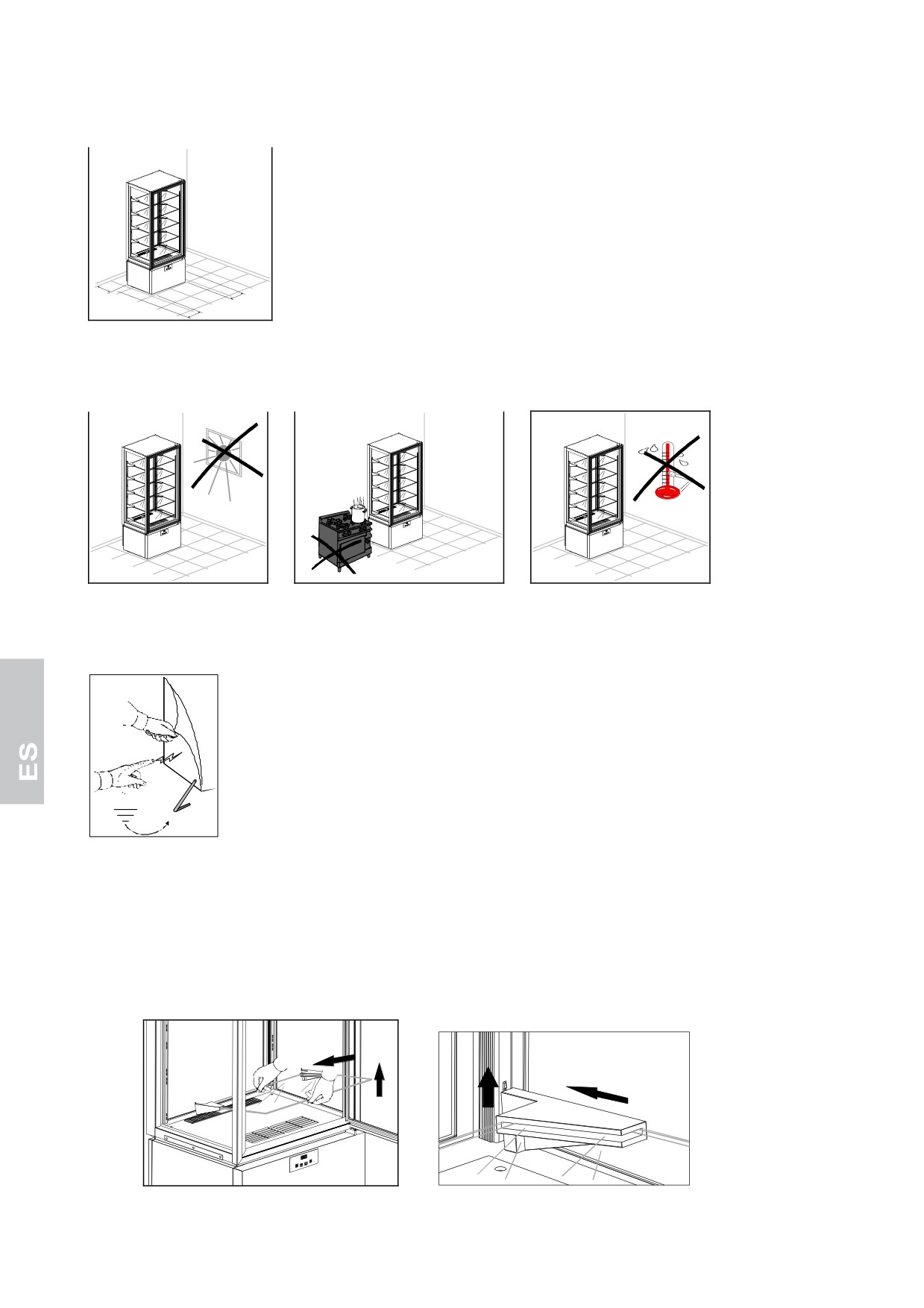
WARNING: Position the unit at least 10 cm away from the rear wall. It is possible to place units side by side,
yet in any case there must be at least 5 cm space between one unit and another.
min.
10 cm
min.
5 cm
min.
5 cm
WARNING: Make sure that the unit is not exposed to direct sunlight, or any other sources of heat nor placed in
environments with high temperatures; any of these would cause the unit to wear more quickly and perform poorly.
The units have been declared to be in the 4 (T = 30° C U.R. = 55%) climate class.
Remove protective film from product.
This may cause unpleasant static electricity discharge which, however, is not dangerous.
The inconvenience is reduced or prevented by continuously holding the refrigerator with one hand or
grounding the package.
Gently remove the shelves paying great attention to not damage them.
Clean the
unit and the shelves as described in the Chapter “CLEANING”. After having cleaned it, leave the
door open at least 72 hours before putting the unit into operation.
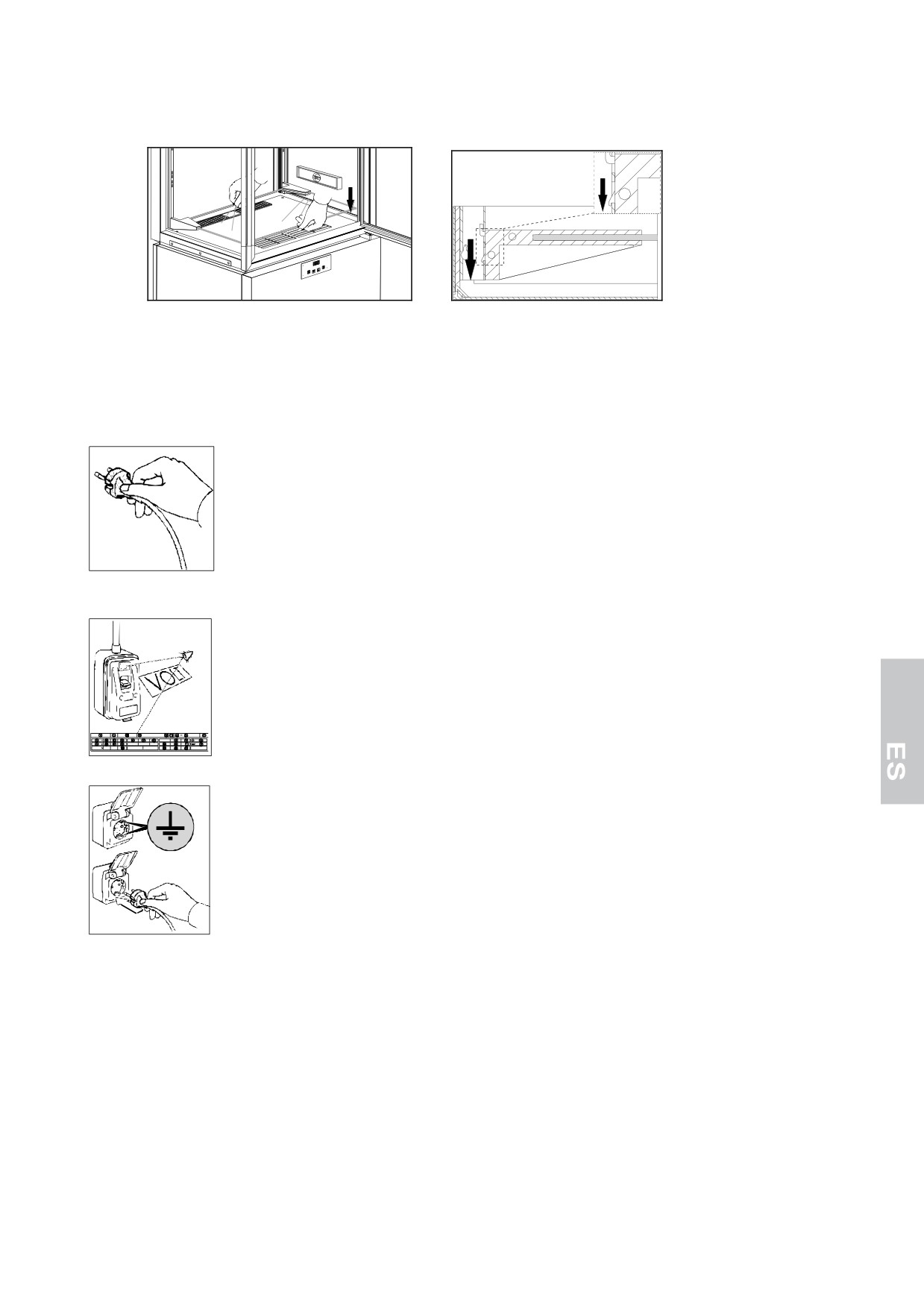
To install the shelves,
follow what is indicated below:
• Beginning from the
lowest shelf, grasp the shelf with both hands.
• Insert the steel hooks into the
rack slots holding the shelf slight tilted upwards.
6
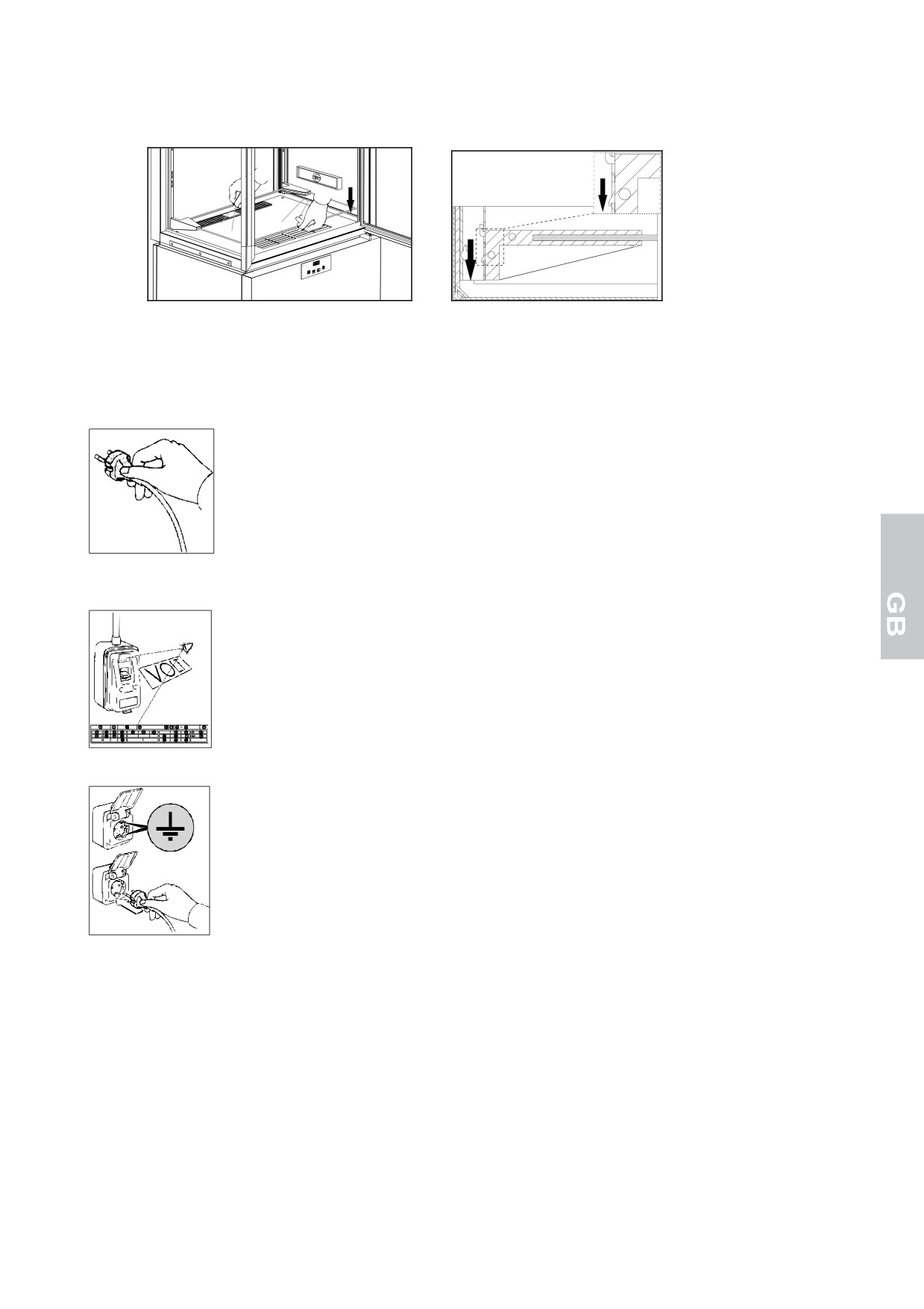
• Lower the shelf
bringing it back
to a horizontal position making sure that the lower hook is inserted
flush into the lower
rack slot.
WARNING: respect for this point is very important to insure the necessary stability of the shelf.
• To unhook the shelf follow the previous directions in reverse order.
The refrigerator is supplied with an electric plug, SHUKO type. Make sure if complies with EN60320 and
national regulations. Otherwise, replace with a complying one.
WARNING: The operation must be carried out by a skilled technician.
Check and verify that the line voltage corresponds to that found on the technical specifications plaque on the
unit.
Then insert the plug into the current tap.
Now the installation has come to end.
7
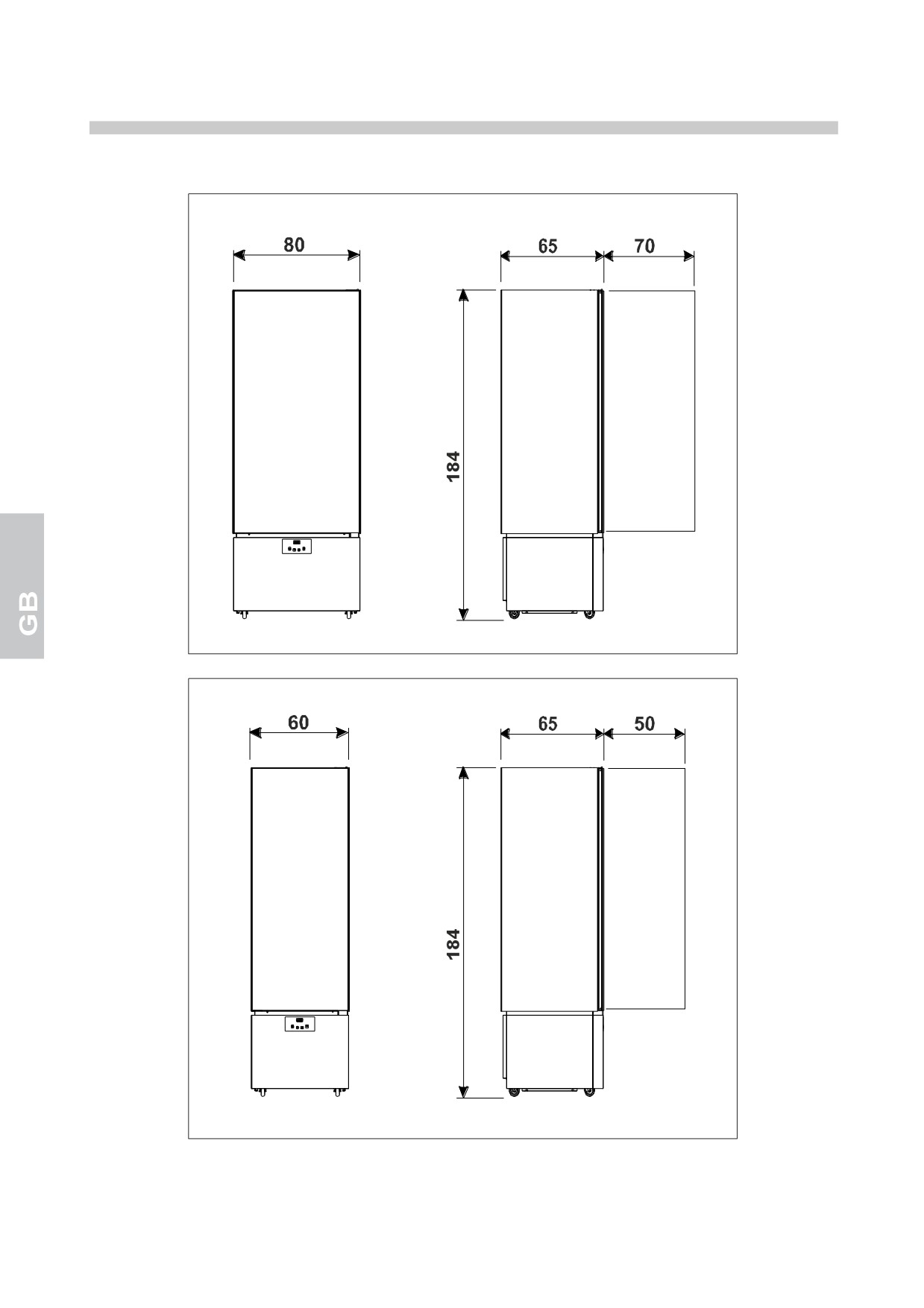
TECHNICAL SPECIFICATIONS
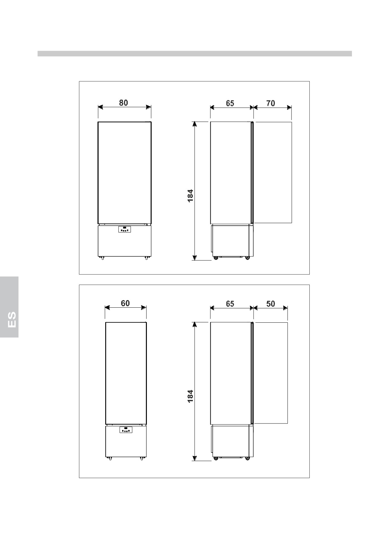
The dimensions of the units are found below.
8
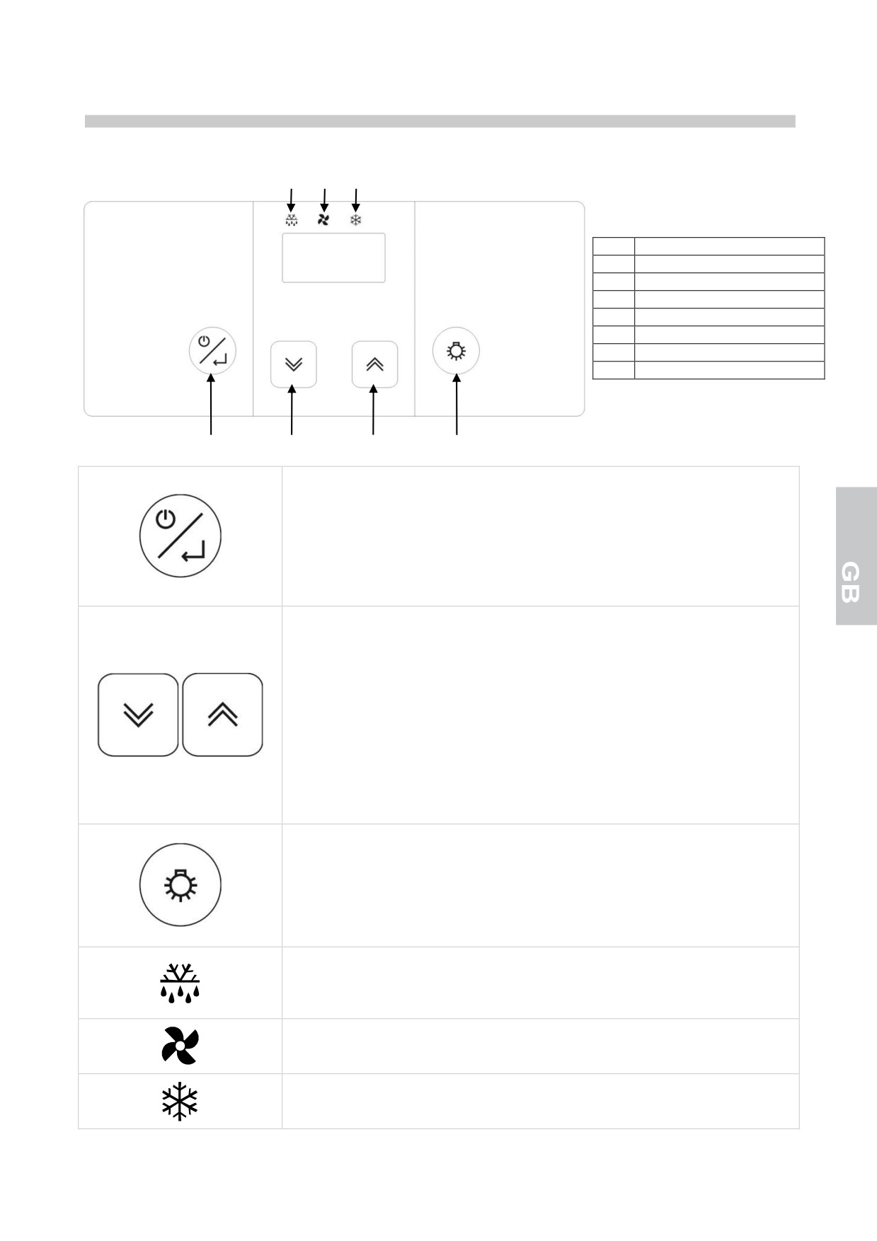
CONTROL PANNELS
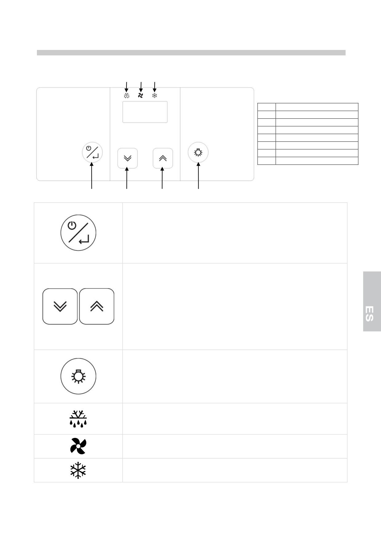
All of the units have the following control panel installed:
5
6
7
POS
DESCRIPTION
1
ON/SBY/ENTER key
2
DOWN key
3
UP key
4
LIGHT key
5
DEFROST ICON
6
FAN ICON
7
COMPRESSOR ICON
1
2
3
4
ON/SBY/ENTER key
Press and release this key to check/change the appliance temperature setpoint.
Press this key for 3 seconds and release it as the display shows the [Sby] to
set the appliance to the stand-by mode.
When holding device in stand-by pressed [the display shows Sby], the
controller turns on.
UP and DOWN keys
These keys allow to increase or decrease the value of the parameter to be
changed.
Press these keys to display the min and max temperature recorded (if
available) and any alarm activated.
Pushed simultaneously these disable the keyboard blocking function.
The UP button, held down for a period exceeding 3 seconds,
activates/deactivates the manual defrost function.
The DOWN button, held down for a period exceeding 3 seconds, allows the
modification of the chamber humidity settings.
LIGHT key
Pushed and released allows the activation or the deactivation of the unit’s
interior illumination.
UNITS +14 °C / +16 °C
Pushed and held down for over 3 seconds allows the temporary visualisation
of the humidity sensor reading, for 5 seconds, in a fixed display mode.
DEFROST ICON
Led on: defrost in progress
Led blinking: defrost activation delay or dripping in progress
Led blinking at high frequency: alarm memorized
FAN ICON
Led on: room fans activated
Flashing LED: ventilator activation delay
COMPRESSOR ICON
Led on: compressor activated
Led blinking: compressor activation delay
9
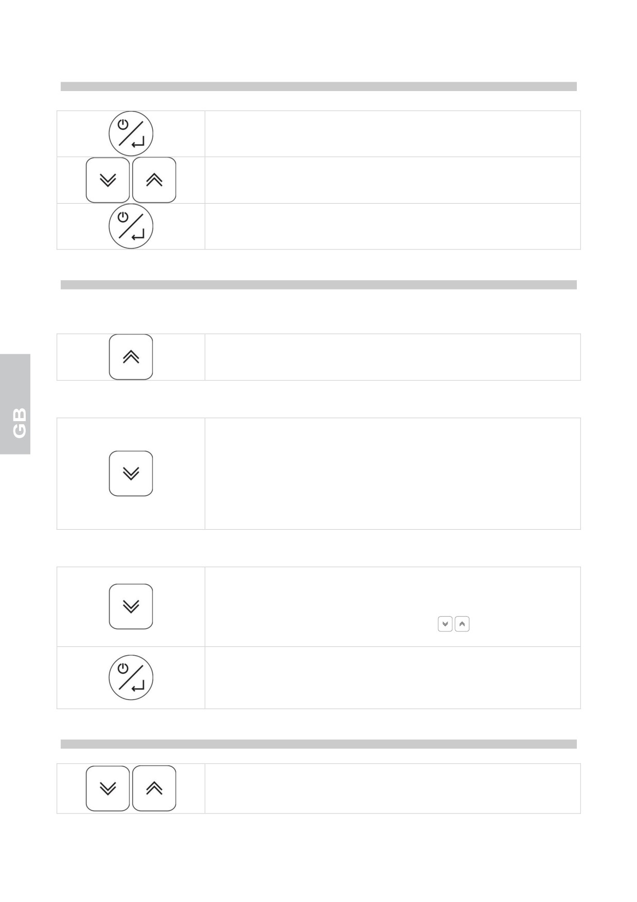
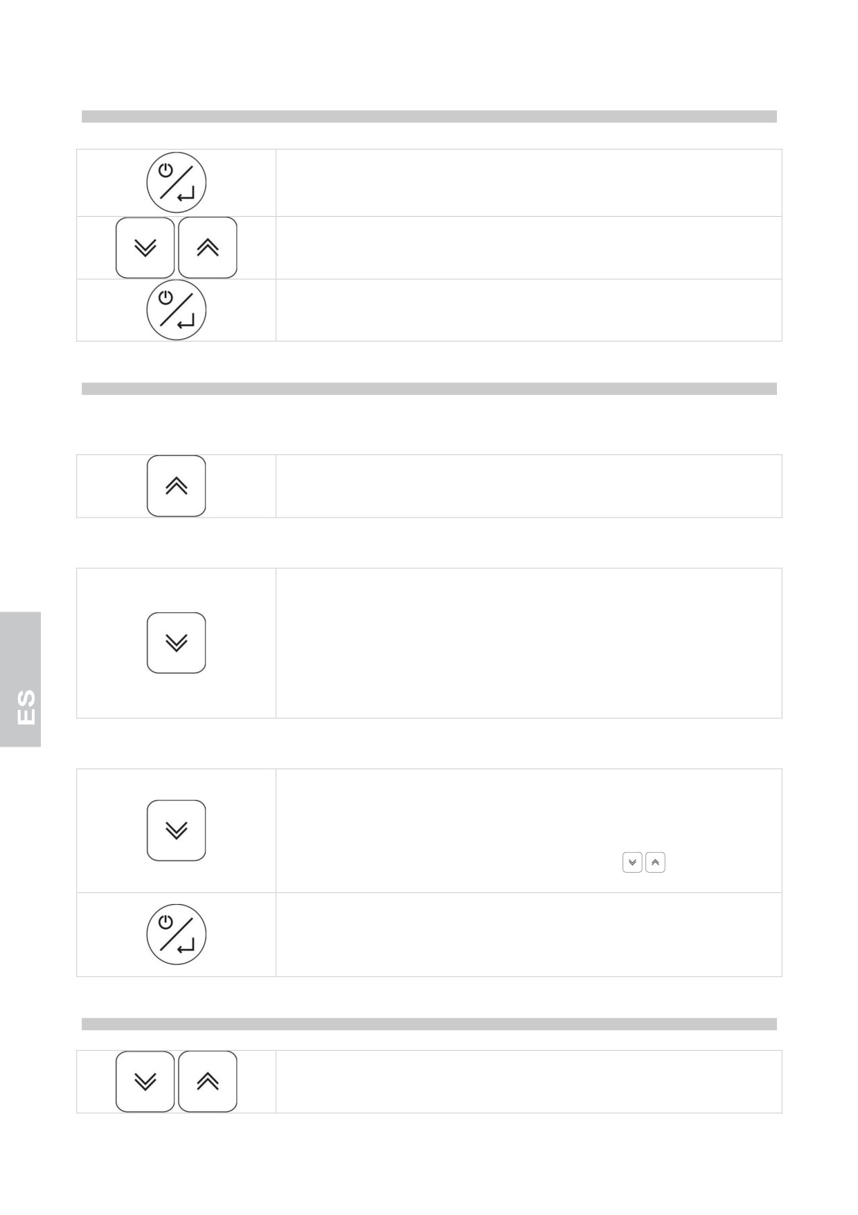
TEMPERATURE SETPOINT SETTING/VARIATION
Press and release the key on/sby/enter: the current setpoint blinks on the
display for 5 seconds.
After 5 seconds, the displays shows the room temperature again
While the display is blinking, use the up and down keys to increase or
decrease the temperature setpoint
Press the on/sby/enter button again to confirm the new set point
SMART FUNCTIONS - Quick-access functions
FORCED MANUAL DEFROST
Push the up button, hold down for more than 3 seconds to access the manual
defrost functions.
CHANGE IN RELATIVE HUMIDITY +2°C/+10°C and -22°C/+5°C
Push the down button, hold down for more than 3 seconds to modify the
percentage of relative humidity in the chamber.
The temporary flashing confirmation label [F_C] corresponds to a too low
relative humidity (fans in parallel with the compressor).
The flashing temporary confirmation label [F_ _] corresponds to a too high
relative humidity (fans independent).
The relative humidity that blinks on the temporary label [FtE] is programmed
by the manufacturer.
CHANGE IN RELATIVE HUMIDITY +14°C/+16°C
Push the down button and hold down for more than 3 seconds: the display
visualises the current humidity setpoint for 5 seconds in a flashing modality.
Once that time has elapsed the display returns to the indication of the
temperature in the cell.
During the flashing mode on the display use the
buttons to increase or
decrease the humidity setpoint desired.
Push the on/sby/enter button to confirm the new setpoint: the acquisition of
the new value is signalled by an acoustic emission of 3 short consecutive
beeps.
After 2 seconds the display returns to the indication of the temperature in the
cell.
BLOCKIEREN DER TASTATUR
Push the up and down buttons simultaneously and hold down for more than 3
seconds.
The label [Loc] is visualised.
10
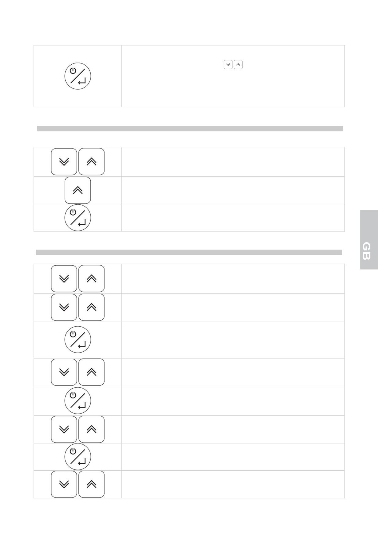
Push the on/sby/enter to confirm the choice and activate the function.
After 30 seconds if not confirmed the program exits the function.
To unblock the keyboard push the
buttons simultaneously and hold
down for more than 5 seconds: to confirm this operation the [UnL] will flash
on the display.
When the keyboard is blocked the label [Loc] will appear on the display when
any key is pressed.
PROBE READING MANUAL PRINTING: Coupled with the TSP print terminal
( only on -25° C / -15° C and -22° C / + 5° C units)
Push the up and down buttons simultaneously and hold down for more than 3
seconds.
The label [Loc] is visualised.
Utilise the up button to visualise the [Prt] function.
Push the on/sby/enter to confirm the choice and activate the function.
After 30 seconds, if not confirmed, the program exits the function.
PARAMETER CONFIGUTATION
Push the up and down buttons simultaneously and hold down for more than 3
seconds.
The label [Loc] is visualised.
Use the up and down keys to display the function [PAr].
Press the on/sby/enter key to enter the parameter configuration mode.
After 30 seconds if not confirmed the program exits the function.
Enter the password to gain access.
The display shows the password setting mode [00]
Use the up and down keys to select the password “65”
Press the on/sby/enter key to confirm your selection.
If the password is correct, the display shows the first parameter in the
configuration list.
Use the up and down keys to scroll the controller parameters
Press the on/sby/enter key to confirm your selection.
Use the keys up and down to select the new value
11
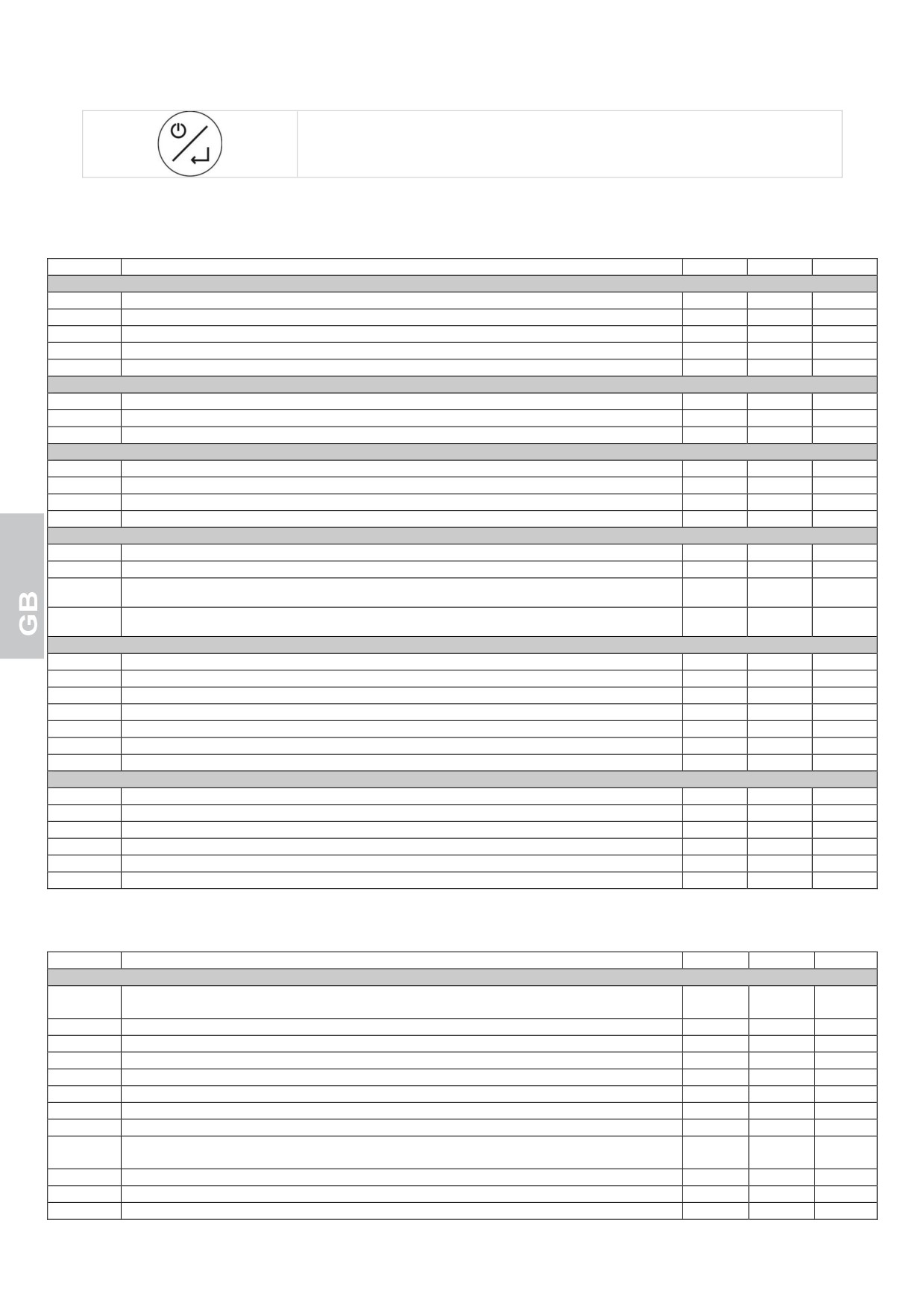
Press the on/sby/enter key to confirm your selection.
PARAMETERS OF CONFIGURATION
“UNITS +2°C/+10°C”
Parameter
Description
Default
min
MAX
MEASUREMENT INPUTS
/1
Room probe calibration (the parameter is expressed in eighths of degree)
0°C
-40
+99
/6
digital input configuration (0 = open contact, 1 = closed contact)
1
0
1
/7
door open alarm delay time (0 = excluded)
120 sec
0
240
Pr
room probe reading
- °C
-
-
Pc
condenser probe reading
- °C
-
-
COMPRESSOR ADJUSTMENT
r0
adjuster hysteresis (differential)
+4°C
1
15
r1
min. operating setpoint selectable
+2°C
-40
r2
r2
max. operating setpoint selectable
+10°C
r1
+99
COMPRESSOR PROTECTION
C0
compressor activation delay from device start
1 min
0
240
C2
min. delay between compr. stop and subsequent start
3 min
0
240
C5
compressor start cycle time in the event of room probe alarm
10 min
1
240
C6
C5 % where compr. starts in the event of room probe alarm
50 %
0
100
DEFROST
d0
defrost interval (0= excluded)
6 hours
0
99
d3
max. defrost duration (0= defrost never activated)
20 min
0
99
d6
defrosting display (0=actual cell temperature,
1
0
2
1=stopped cell temperature, 2=dEF label)
dE
defrost interval count:
0
0
1
0= actual hours; 1=hours comp. ON; 2= autodeterm.
ALARMS
A0
alarm hysteresis (differential)
+2 °C
1
15
A1
min. operating setpoint alarm (0= excluded)
-2 °C
-40
0
A2
max. operating setpoint alarm (0= excluded)
+15 °C
0
+99
A3
alarm exclusion from device start
120 min
0
240
A4
buzzer activation mode for alarm : 0= always; 1= timer-controlled
1
0
1
A5
time limit for buzzer acoustic signal (only if A4 = 1)
1 min
0
240
A6
temperature alarm exclusion time (only if A1 and/or A2 0)
15 min
0
240
EVAPORATOR FAN ADJUSTMENT
F3
evaporator fan func. during regular operation (0=OFF; 1=ON; 2=parallel with compressor)
1
0
2
F6
temperature below which the condenser fan turns off
20°C
-40
+99
F7
condenser fan differential (relating to F6)
+3°C
1
25
F8
condenser fan func. during regular operation (0=parallel with compr.; 1=ON); also refer to F6 and F7
0
0
1
FA
critical temperature for signalling high condensation temperature
46°C
-40
+99
Fb
critical temperature for high pressure akarm
49°C
-40
+99
“UNITS -25°C/-15°C”
Parameter
Description
Default
min
MAX
MEASUREMENT INPUTS
/1
Room probe calibration (the parameter is expressed in eighths of degree)
-16
-40
+99
(eighths °C
/2
evaporator probe activation (0=off;1=on)
0
0
1
/3
condenser probe activation (0=off; 1=on)
1
0
1
/6
digital input configuration (0 = open contact, 1 = closed contact)
0
0
1
/7
door open alarm delay time (0 = excluded)
120 s
0
240
/A
setpoint attivazione resistenza porta (solo se /9 = 0)
-7 °C
-40
+99
/b
door resist. activation adjustment hysteresis (only if /9 =0)
2 °C
1
15
/E
Sensor probe visualisation management (0 = normal, 1 = limited from above r0)
1
0
1
/F
defrost relay defrost management (0 = de-energized when the value set with d2 is reached on the
0
0
1
evaporator, 1 = de-energized at the end of time d7)
Pr
room probe reading
- °C
-
-
Pd
defrost/evaporator probe reading
- °C
-
-
Pc
condenser probe reading
- °C
-
-
12
COMPRESSOR ADJUSTMENT
r0
adjuster hysteresis (differential)
+2 °C
1
15
r1
min. operating setpoint selectable
-25 °C
-40
r2
r2
max. operating setpoint selectable
-15 °C
r1
+99
COMPRESSOR PROTECTION
C0
compressor activation delay from device start
1 min
0
240
C2
min. delay between compr. stop and subsequent start
3 min
0
240
C5
compressor start cycle time in the event of room probe alarm
10 min
1
240
C6
C5 % where compr. starts in the event of room probe alarm
70 %
0
100
DEFROST
d0
defrost interval (0= excluded)
0 hours
0
99
d1
defrost type (0= resistance, 1= hot-gas)
0
0
1
d2
end-of-defrost temp. (relating to evaporator temper.)
+12 °C
-40
+99
d3
max. defrost duration (0 = the defrosting function will not start; 255 = the defrosting function will go
255 min
0
255
on continuously)
d6
defrosting display (0=actual cell temperature, 1=stopped cell temperature, 2=dEF label)
1
0
2
d7
dripping time
4 min
0
15
dE
defrost interval count:
0= actual hours; 1=hours comp. ON; 2= autodeterm.
0
0
1
ALARMS
A0
alarm hysteresis (differential)
+2 °C
1
15
A1
min. operating setpoint alarm (0= excluded)
-2 °C
-40
0
A2
max. operating setpoint alarm (0= excluded)
+15 °C
0
+99
A3
alarm exclusion from device start
120 min
0
240
A4
buzzer activation mode for alarm : 0= always; 1= timer-controlled
1
0
1
A5
time limit for buzzer acoustic signal (only if A4 = 1)
20 s
0
240
A6
temperature alarm exclusion time (only if A1 and/or A2
0)
15 min
0
240
A7
temp. alarm exclusion time after evap. stop (for A1 and/or A2
0)
60 min
0
240
ADJUSTING THE EVAPORATOR AND CONDENSER VANS
F1
temper. above which the evap. fan stops ( only if /A = 1 and F7 = 3 or 4)
-1 °C
-40
+99
F2
fan differential (relating to F1, only if /A = 1 and F7 = 3 or 4)
+2 °C
1
15
F3
evaporator fan func. during regular operation (0=OFF; 1=ON; 2=parallel with compressor;
2
0
4
3=determined by F1 and F2 with comp. ON and OFF with comp. OFF
F4
evap. vent. operation during defrost and dripping (0= OFF, 1= ON, 2= determ. with F7)
0
0
2
F5
evaporator fan stop after dripping
3 min
0
15
F6
temperature below which the condenser fan turns off
10 °C
-40
+99
F7
condenser fan differential (relating to F6)
+3 °C
1
25
F8
condenser fan func. during regular operation (0=parallel with compr.; 1=ON); also refer to F6 and F7
0
0
1
F9
condenser fan func. during defrost and dripping (0=OFF; 1=ON, 2=ON if Tc≥26°C and OFF if
2
0
2
Tc<25°C)
FA
critical temperature for signalling high condensation temperature
46 °C
-40
+99
Fb
critical temperature for condenser dirty alarm
48 °C
-40
+99
Fc
time the condenser probe stays on the value equal or higher than FA for activation of the HtC alarm
5 min
0
240
Fd
time the condenser probe stays on the value equal or higher than Fb for activation of the dCA alarm
1 min
0
240
FE
temperature increase on the device set point value in case of an active dCA alarm
5 °C
1
15
FF
critical temperature for high pressure alarm
55 °C
-40
+99
FH
time limit used to pass from the FA value to the Fb value, within which the HP alarm is however
12 s
0
15
activated
FL
critical temperature for signalling low evaporation temperature
-37 °C
-40
+99
Fn
time the evaporator probe stays on the value equal or higher than FL for activation of the LtE alarm
30 min
0
240
Fo
time the LtE alarm stays, upon reaching of which automatic defrosting is forced
30 min
0
240
FP
critical temperature for low pressure alarm
-41 °C
-42
+99
PRINT
P0
Configuration parameters printing enable (0 = disabled)
1
0
1
P1
Sampling time (see also parameter P6)
60
1
60
min/hours
P2
Selection of temperature probe to be printed (0 = none, 1=chamber probe, 2 = chamber and
1
0
3
evaporator probe)
P3
Payslip heading selection (0 =excluded, 1 = BTV Display Case, 2 = BTS Display Case)
2
0
2
P4
Equipment identification number printing enable (0 = no, 1= yes)
1
0
1
P5
Selection of language for payslip heading (1=Italian, 2=English, 3=French, 4=Spanish, 5=German)
1
-1
5
P6
Selection of unit of measure for sampling time (1 = minutes, 2 =hours)
1
1
2
COMMUNICATIONS MANAGEMENT
L1
Instrument address (date detected in printing phase if P4 = 1)
1
0
255
L2
Serial port management (o = not utilised, 1 = print)
1
0
1
L3
Baud Rate data transmiss. (1=2400, 2=4800, 3=9600, 4=18200)
3
1
4
L4
Transmission control mode (0 = no parity, 1 = odd, 2 = even)
0
0
2
13
“UNITS -22°C/+5°C”
Parameter
Description
Default
min
MAX
MEASUREMENT INPUTS
/1
Room probe calibration (the parameter is expressed in eighths of degree)
+8
-40
+99
(eighths °C)
/2
evaporator probe activation (0=off;1=on)
1
0
1
/3
condenser probe activation (0=off; 1=on)
1
0
1
/6
digital input configuration (0 = open contact, 1 = closed contact)
1
0
1
/7
door open alarm delay time (0 = excluded)
120 s
0
240
/A
setpoint attivazione resistenza porta (solo se /9 = 0)
-7 °C
-40
+99
/b
door resist. activation adjustment hysteresis (only if /9 =0)
2 °C
1
15
/E
Sensor probe visualisation management (0 = normal, 1 = limited from above r0)
1
0
1
/F
defrost relay defrost management (0 = de-energized when the value set with d2 is reached on the
1
0
1
evaporator, 1 = de-energized at the end of time d7)
Pr
room probe reading
- °C
-
-
Pd
defrost/evaporator probe reading
- °C
-
-
Pc
condenser probe reading
- °C
-
-
COMPRESSOR ADJUSTMENT
r0
adjuster hysteresis (differential)
+3 °C
1
15
r1
min. operating setpoint selectable
-22 °C
-40
r2
r2
max. operating setpoint selectable
+5 °C
r1
+99
COMPRESSOR PROTECTION
C0
compressor activation delay from device start
1 min
0
240
C2
min. delay between compr. stop and subsequent start
3 min
0
240
C5
compressor start cycle time in the event of room probe alarm
10 min
1
240
C6
C5 % where compr. starts in the event of room probe alarm
70 %
0
100
DEFROST
d0
defrost interval (0= excluded)
4 hours
0
99
d1
defrost type (0= resistance, 1= hot-gas)
1
0
1
d2
end-of-defrost temp. (relating to evaporator temper.)
+12 °C
-40
+99
d3
max. defrost duration (0 = the defrosting function will not start; 255 = the defrosting function will go
20 min
0
255
on continuously)
d6
defrosting display (0=actual cell temperature, 1=stopped cell temperature, 2=dEF label)
1
0
2
d7
dripping time
4 min
0
15
dE
defrost interval count:
0= actual hours; 1=hours comp. ON; 2= autodeterm.
1
0
1
ALARMS
A0
alarm hysteresis (differential)
+2 °C
1
15
A1
min. operating setpoint alarm (0= excluded)
-2 °C
-40
0
A2
max. operating setpoint alarm (0= excluded)
+15 °C
0
+99
A3
alarm exclusion from device start
120 min
0
240
A4
buzzer activation mode for alarm : 0= always; 1= timer-controlled
1
0
1
A5
time limit for buzzer acoustic signal (only if A4 = 1)
20 s
0
240
A6
temperature alarm exclusion time (only if A1 and/or A2
0)
15 min
0
240
A7
temp. alarm exclusion time after evap. stop (for A1 and/or A2
0)
60 min
0
240
ADJUSTING THE EVAPORATOR AND CONDENSER VANS
F1
temper. above which the evap. fan stops ( only if /A = 1 and F7 = 3 or 4)
-1 °C
-40
+99
F2
fan differential (relating to F1, only if /A = 1 and F7 = 3 or 4)
+2 °C
1
15
F3
evaporator fan func. during regular operation (0=OFF; 1=ON; 2=parallel with compressor;
2
0
4
3=determined by F1 and F2 with comp. ON and OFF with comp. OFF
F4
evap. vent. operation during defrost and dripping (0= OFF, 1= ON, 2= determ. with F7)
0
0
2
F5
evaporator fan stop after dripping
3 min
0
15
F6
temperature below which the condenser fan turns off
10 °C
-40
+99
F7
condenser fan differential (relating to F6)
+3 °C
1
25
F8
condenser fan func. during regular operation (0=parallel with compr.; 1=ON); also refer to F6 and F7
0
0
1
F9
condenser fan func. during defrost and dripping (0=OFF; 1=ON, 2=ON if Tc≥26°C and OFF if
2
0
2
Tc<25°C)
FA
critical temperature for signalling high condensation temperature
46 °C
-40
+99
Fb
critical temperature for condenser dirty alarm
48 °C
-40
+99
Fc
time the condenser probe stays on the value equal or higher than FA for activation of the HtC alarm
5 min
0
240
Fd
time the condenser probe stays on the value equal or higher than Fb for activation of the dCA alarm
1 min
0
240
FE
temperature increase on the device set point value in case of an active dCA alarm
5 °C
1
15
FF
critical temperature for high pressure alarm
55 °C
-40
+99
FH
time limit used to pass from the FA value to the Fb value, within which the HP alarm is however
12 s
0
15
activated
FL
critical temperature for signalling low evaporation temperature
-37 °C
-40
+99
14
Fn
time the evaporator probe stays on the value equal or higher than FL for activation of the LtE alarm
30 min
0
240
Fo
time the LtE alarm stays, upon reaching of which automatic defrosting is forced
30 min
0
240
FP
critical temperature for low pressure alarm
-41 °C
-42
+99
PRINT
P0
Configuration parameters printing enable (0 = disabled)
1
0
1
P1
Sampling time (see also parameter P6)
60
1
60
min/hours
P2
Selection of temperature probe to be printed (0 = none, 1=chamber probe, 2 = chamber and
1
0
3
evaporator probe)
P3
Payslip heading selection (0 =excluded, 1 = BTV Display Case, 2 = BTS Display Case)
1
0
2
P4
Equipment identification number printing enable (0 = no, 1= yes)
1
0
1
P5
Selection of language for payslip heading (1=Italian, 2=English, 3=French, 4=Spanish, 5=German)
1
-1
5
P6
Selection of unit of measure for sampling time (1 = minutes, 2 =hours)
1
1
2
COMMUNICATIONS MANAGEMENT
L1
Instrument address (date detected in printing phase if P4 = 1)
1
0
255
L2
Serial port management (o = not utilised, 1 = print)
1
0
1
L3
Baud Rate data transmiss. (1=2400, 2=4800, 3=9600, 4=18200)
3
1
4
L4
Transmission control mode (0 = no parity, 1 = odd, 2 = even)
0
0
2
“UNITS +14°C/+16°C”
Parameter
Description
Default
min
MAX
MEASUREMENT INPUTS
/1
Room probe calibration (the parameter is expressed in eighths of degree)
0°C
-40
+99
/6
digital input configuration (0 = open contact, 1 = closed contact)
1
0
1
/7
door open alarm delay time (0 = excluded)
120 sec
0
240
/H
Measurement input visualisation modes (0 = only cell sensor, 1= cell sensor and humidity sensor
0
0
1
scanned every 5 seconds)
Pr
room probe reading
- °C
-
-
PrH
Humidity sensor read out
-%
-
-
COMPRESSOR ADJUSTMENT
r0
adjuster hysteresis (differential)
+4°C
1
15
r1
min. operating setpoint selectable
+14°C
-40
r2
r2
max. operating setpoint selectable
+16°C
r1
+99
r3
Relative humidity adjustment hysteresis (differential)
5%
0%
15%
r4
Dead zone relative humidity adjustment
1%
0%
10%
r5
Relative humidity adjustable minimum setpoint
40%
20%
80%
r6
Relative humidity adjustable maximum setpoint
50%
20%
80%
COMPRESSOR PROTECTION
C0
compressor activation delay from device start
1 min
0
240
C2
min. delay between compr. stop and subsequent start
2 min
0
240
C5
compressor start cycle time in the event of room probe alarm
10 min
1
240
C6
C5 % where compr. starts in the event of room probe alarm
40 %
0
100
DEFROST
d0
defrost interval (0= excluded)
0 hours
0
99
d3
max. defrost duration (0 = the defrosting function will not star)
5 min
0
99
d6
defrosting display (0=actual cell temperature, 1=stopped cell temperature, 2=dEF label)
1
0
2
dE
defrost interval count:
0= actual hours; 1=hours comp. ON; 2= autodeterm.
0
0
2
ALARMS
A0
alarm hysteresis (differential)
+2 °C
1
15
A1
min. operating setpoint alarm (0= excluded)
-2 °C
-40
0
A2
max. operating setpoint alarm (0= excluded)
+15 °C
0
+99
A3
alarm exclusion from device start
120 min
0
240
A4
Buzzer alarm activation modality (0 = always; 1 = timed)
1
0
1
A5
Time limit for alarm buzzer acoustic notification (only if A4 = 1)
1 min
0
240
A6
temperature alarm exclusion time (only if A1 and/or A2 0)
60 min
0
240
EVAPORATOR FAN ADJUSTMENT
F3
evaporator fan func. during regular operation (0=OFF; 1=ON; 2=parallel with compressor)
1
0
2
F6
temperature below which the condenser fan turns off
20°C
-40
+99
F7
condenser fan differential (relating to F6)
+3°C
1
25
F8
condenser fan func. during regular operation (0=parallel with compr.; 1=ON); also refer to F6 and F7
0
0
1
F9
condenser fan func. during defrost and dripping (0=OFF; 1=ON, 2=ON if Tc≥35°C and OFF if
2
0
2
Tc<33°C)
FA
critical temperature for signalling high condensation temperature
41°C
-40
+99
Fb
critical temperature for high pressure akarm
44°C
-40
+99
15
USER PARAMETER CONFIGURATION - PROBE READING
Push the up and down buttons simultaneously and hold down for more than 3
seconds.
The label [Loc] is visualised.
Utilise the up and down buttons to scroll the sensor probe readings and the
user parameters.
Press the on/sby/enter key to confirm your selection and enter the mode for
reading probes or changing parameters.
The current value blinks on the display.
Use the keys
to select the new value, applicable to parameters only.
Press the on/sby/enter key to exit or confirm the selection of the parameter
new value; the setting stops blinking.
DEFAULT PARAMETER RECOVERY
Information accessible to qualified staff only.
On starting the appliance, a “LAMPTEST” phase will start.
If you press the on/sby/enter key 3 times consecutively during this phase, all
default parameters will be reset.
The display shows [rLd] indicating the reset of the values pre-set by the
manufacturer.
ATTENTION: the default values in memory refer to the configurations (tn, bts, btv) exclusively.
ALARMS
UNIT WITH BROKEN SENSOR PROBES DURING CONSERVATION
Room probe error
If the room probe is broken or the relevant connection interrupted, the display shows the label [E0].
The appliance keeps operating in storing according to the values given to parameters C5 and C6.
The inner fan keeps operating according to the value given to “F3”
Evaporator fan error (only on -22°C / +5°C units)
If the room probe is broken or the relevant connection interrupted, the display shows the label [E1].
The inner fan operates according to the value given to parameter “F3”.
If the three probes are broken or disconnected, E0, E1, and E2 alternate on the display.
Humidity sensor Error (only on +14°C/+16°C units)
In the event that the humidity sensor is broken or its connection is interrupted on the display the label [E8], is
visualised; the humidity control device is automatically deactivated.
Condenser probe error
If the condenser probe is broken or the relevant connection interrupted, the display shows the label [E2].
16
The condenser fan keeps operating according to the value given to parameter “F8”.
If the three probes are broken or disconnected, E0, E1, and E2 alternate on the display.
UNIT WITH BROKEN SENSOR PROBES DURING DEFROST
Room probe error
In the event that the chamber sensor probe is broken or the respective connection has been interrupted
during the defrost phase the function will be completed normally.
The string set with the parameter “d6” and the label [E0] will be visualised alternatively on the display.
Evaporator fan error (only on -22°C / +5°C units)
In the event that the evaporator sensor probe is broken or the respective connection has been interrupted
during the defrost phase the function will be completed through time out.
The evaporator fan will continue to operate according to the value assigned with the “F4” parameter.
The melting times “d7” and the internal fan activation delay “F5” will be observed in any case.
A display viene visualizzata alternativamente la stringa settata con il parametro “d6” e la label [E1].
If the three probes are broken or disconnected, E0, E1, and E2 alternate on the display.
Humidity sensor Error (only on +14°C/+16°C units)
In the event that the humidity sensor is broken or its connection is interrupted on the display the label [E8], is
visualised; the humidity control device is automatically deactivated.
Condenser probe error
If the condenser probe is broken or the relevant connection interrupted, the display shows the label [E2].
The condenser fan keeps operating according to the value given to parameter “F8”.
If the three probes are broken or disconnected, E0, E1, and E2 alternate on the display.
DOORFRAME SECTIONS ANTICONDENSATION RESISTANCE HEATER MANAGEMENT
(only on -25°C / -15°C and -22°C /+ 5°C units)
In the event that the chamber sensor probe is broken or its respective connection interrupted, the machine will
continue to operate managing the activation/deactivation of the door resistance heater in parallel with the
activation/deactivation of the compressor relay.
HIGH TEMPERATURE ALARM
If the room temperature exceeds the setpoint, the label [AH] and the
temperature reached alternate on the display.
Press up to display the duration of the event causing the alarm.
The buzzer can be turned off by pressing the key .
The visual alarm signal stays on until the temperature returns within the normal range.
LOW TEMPERATURE ALARM
If the room temperature is below the setpoint, the label [AL] and the
temperature reached alternate on the display. The buzzer sounds.
Press down to display the duration of the event causing the alarm.
The buzzer can be turned off by pressing the key .
The visual alarm signal stays on until the temperature returns within the normal range.
17
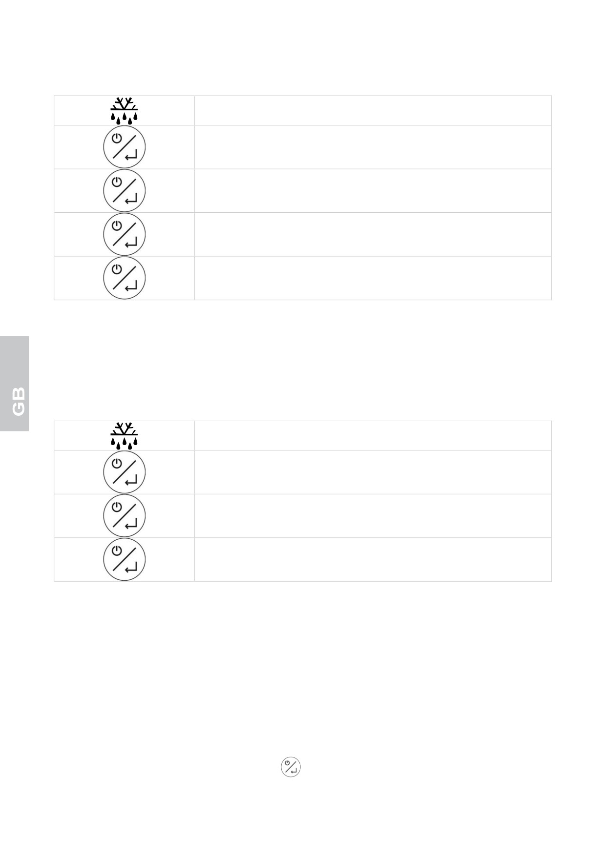
HIGH AND LOW TEMPERATURE ALARMS MEMORIZED
The defrost led blinking at high frequency indicates high or low temperature
alarm.
Pushing the on/sby/enter button the type of alarm recorded will be visualised
on the flashing display.
Pushing the on/sby/enter button the critical temperature recorded will be
visualised on the flashing display.
Pushing the on/sby/enter button the time duration of alarm event, expressed
in minutes, will be visualised on the flashing display.
Pushing the on/sby/enter button the operation of the defrost LED will be reset
to its normal state.
The display shows [rES] after the abnormal event.
In the event that another alarm event were to occur, for high or low temperature, if the information relative to the
preceding anomaly hasn’t been visualised by the operator, this latter will be overwritten by the more recent data.
If the high temperature alarm is on, the compressor keeps working; if the low temperature alarm is on, the
compressor stops.
! If the card is set to the stand-by mode, the min. / max. temperature memorized and any alarms will
not be saved.
BLACKOUT ALARM
The defrost led blinking at high frequency indicates a blackout
Pushing the on/sby/enter button the [bLO] label will be visualised on the
display.
Pushing the on/sby/enter button the maximum temperature recorded in the
chamber will be visualised on the display.
Pushing the on/sby/enter button the defrost led is reset to standard operation.
The display shows [rES] after the abnormal event.
OPEN DOOR ALARM
In the event of a door open the display will visualise the [dA] label alternating with the current visualisation
while the buzzer, if present, will signal the event acoustically with a beep of the duration of 5 seconds
repeated every 10 seconds.
The alarm will reset upon the closure of the door and is registered in memory (high frequency flashing
defrost LED).
HIGH CONDENSATION TEMPERATURE ALARM
If the condensation temperature is too high, due to dirty condenser, the label [HtC] and the room temperature
alternate on the display.
The buzzer sounds.
The buzzer can be turned off by pressing the key
The visual warning signal stays on until the condensation tempertaure returns to normal range.
18
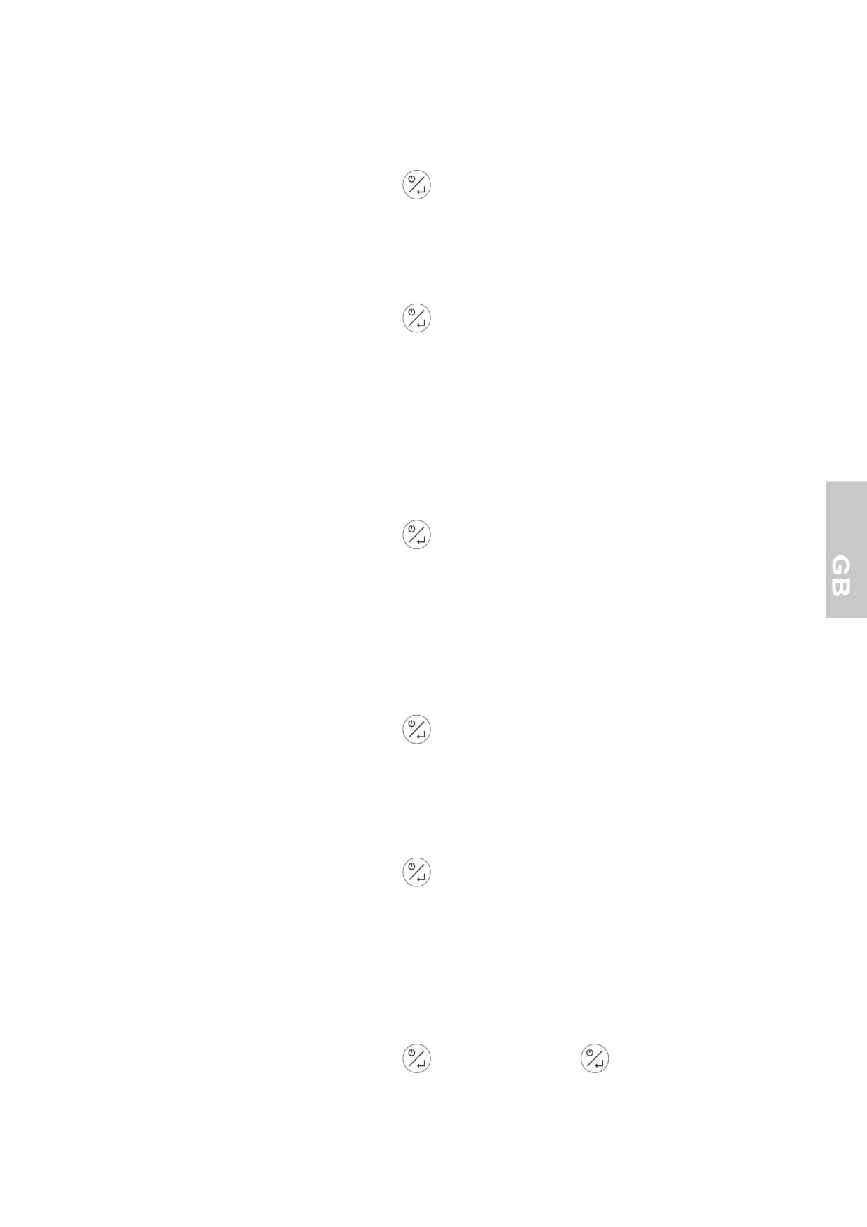
HIGH CONDENSATION TEMPERATURE ALARM (only on -25°C / -15°C and -22°C /+ 5°C units)
If the condensation temperature is high because the condenser is dirty, the label[ HtC] alternating with the
cell temperature will be shown on the display. A buzzer is also activated.
The buzzer can be turned off by pressing the key
The visual warning signal stays on until the condensation tempertaure returns to normal range.
CONDENSER DIRTY ALARM (only on -25°C / -15°C and -22°C /+ 5°C units)
If the condensation temperature is too high because the condenser is very dirty, the label [dCA] alternating
with the cell temperature will be shown on the display. A buzzer is also activated.
The buzzer can be turned off by pressing the key
The visual warning signal stays on until the condensation tempertaure returns to normal range.
In parallel, the operating set point of the device changes automatically to safeguard plant conditions.
The new setting remains until the condensation temperature returns within the normal range.
HIGH PRESSURE ALARM
If the refrigerating appliance pressure is above the specified limit, the label
[HP] and the room temperature
alternate on the display.
The buzzer sounds.
The buzzer can be turned off by pressing the key
The visual warning signal stays on until the card is set to stand-by.
! If the problem causing the alarm reoccurs on restarting the system, the signal [HP] will be displayed again.
In this case, all the relay outputs are de-activated except the condenser fan output.
LOW EVAPORATION TEMPERATURE ALARM (only on -25°C / -15°C and -22°C /+ 5°C units)
If the evaporation temperature is too low because of the packaged evaporator, the label [LtE] alternating with
the cell temperature will be shown on the display. A buzzer is also activated.
The buzzer can be turned off by pressing the key
The visual alarm signal remains until the evaporation temperature returns within the normal range.
If this does not occur, the machine carries out automatic defrosting.
LOW PRESSURE ALARM (only on -25°C / -15°C and -22°C /+ 5°C units)
If a refrigeration system pressure is detected that is lower than the limit values, the label [LP] alternating with
the cell temperature will be shown on the display. A buzzer is also activated.
The buzzer can be turned off by pressing the key
The visual warning signal stays on until the card is set to stand-by.
! If the problem causing the alarm reoccurs on restarting the system, the signal [LP] will be displayed again.
All relay outputs will be deactivated during this event.
ALARM FOR END OF DEFROSTING ENDING DUE TO TIMEOUT (only on -25°C / -15°C and -22°C /+
5°C units)
In the event that the evaporator probe has not reached the pre-set value at the end of defrosting, the label
[tOd] alternating with the cell temperature will be shown on the display.
The buzzer can be turned off by pressing the key
. Pressing the next key
resets the alarm
19
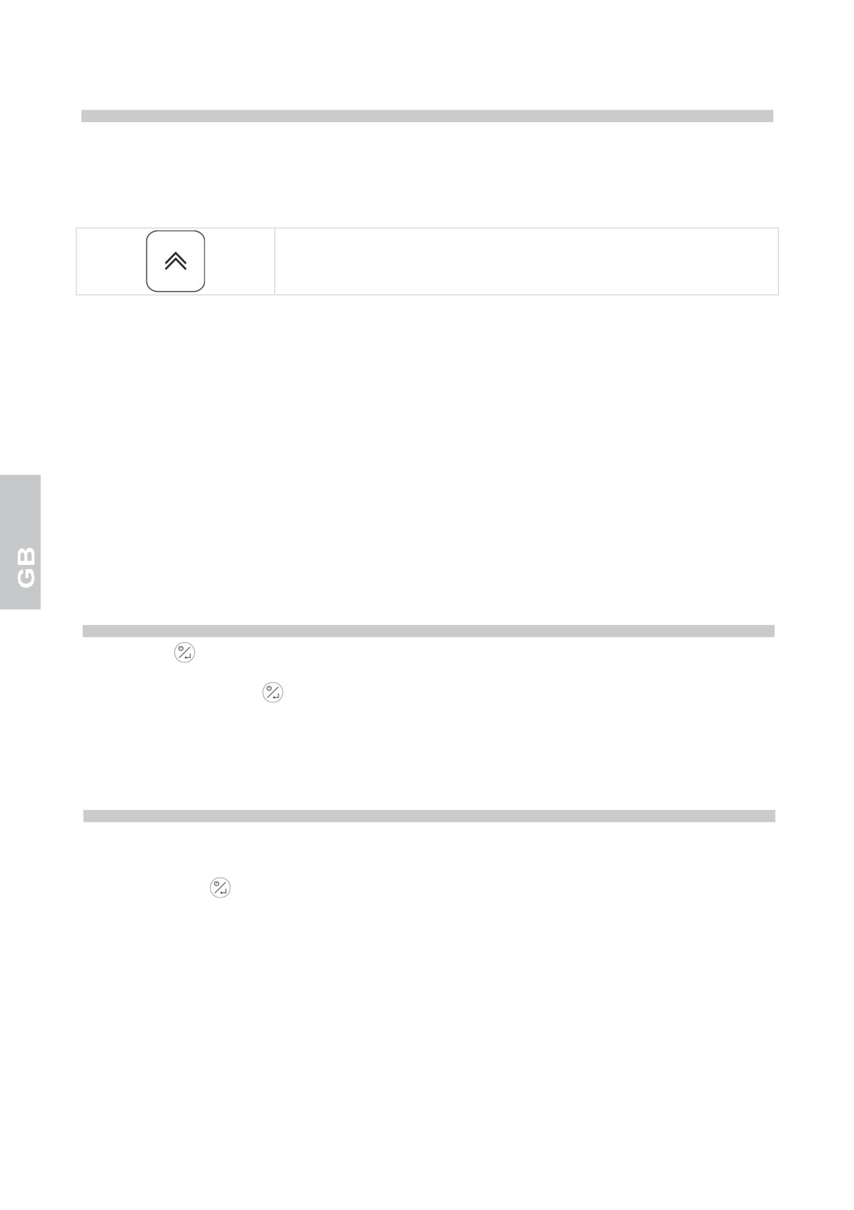
DEFROSTING
Defrost may be either manual type or automatic type.
Manual defrost
Models +2°C / +10°C, -22°C / +5°C, +14°C / +16°C
Push the button up for 4 sec seconds to immediately activate the defrost
cycle.
Just before the defrosting process begins, the temperature of the blocked cell
is displayed.
The defrosting process can be stopped manually by pressing the “up” key again for 4 seconds. When the
process is stopped, a signal blinks on the label display [ndF].
Models -25°C / -15°C
In the -25°C / -15°C models, the defrost function must be activated by the user whenever a thick layer of
frost accumulates upon the shelves. In order to defrost the unit, turn it off by setting the panel to stand-by
mode, then open the door and remove the products. Remove the cap on the bottom and wait for all the frost
to melt. Use a sponge to direct all the water on the bottom into the drain hole. Clean the unit’s interior
surfaces with a dry cloth and replace the cap on the bottom.ù
Automatic defrost
Automatic defrost is started during the conservation phase and is regulated by the card set-up.
The defrost operation can be manually interrupted by pressing the up button for 4 seconds: the deactivation
of the function will be indicated by the [ndF] label flashing on the display.
On the +14 °C / +16 °C and -25°C / -15°C units there is no automatic defrost".
STOPPING
Press this key
for 3 seconds and release it as the display shows the [Sby] to set the appliance to the
stand-by mode.
WARNING: the main switch
DOES NOT insulate the machine from the electric current.
Set the general cut-out in OFF position.
To isolate the unit from electrical tension disconnect its plug from the outlet.
WORKING IRREGULARITIES
In case of working irregularities, before to call the technical service in zone verify that:
the main switch
is lighting and the current is present;
the regulated temperature is the wished one;
that the door is perfectly closed;
the machine is not near heat sources;
the condenser is clean and the fan works regularly;
an excess of hoarfrost does not cover the evaporating pannel.
In case of negative result, contact the nearest service centre indicating the model and the serial number
shown on the rating placed on the appliance instrument panel.
20
DAILY CLEANING
To guarantee perfect hygiene and conservation of the unit it is well to carry out regular and/or daily cleaning
operations.
Avoid using abrasive creams or stainless steel wool pads, acetone, chlorylene or ammonia.
Use only a solution of water and bicarbonate.
Any food stains or residue on the outside surface should be removed with water before they harden.
If residues are already hardened used a sponge soaked in a solution of water and bicarbonate.
Daily cleaning of all inside surfaces of the appliance is recommended.
Clean the shelves and the interior of the unit with a lightly dampened cloth.
The space around and under the refrigerator must also be cleaned and held in perfect hygiene.
Clean using water and neutral soap or detergent.
GENERAL CLEANING AND MAINTENANCE
For regular and constant service of the unit it would be well to regularly carry out general cleaning and
maintenance operations.
WARNING: The cleaning and mantainance of the refrigerating engine and the compressor area needs the
intervention of a skilled technician, therefore it cannot be done by other persons.
Clean the exterior and interior surfaces with soap or a neutral detergent and water: a little vinegar added to
the water will eliminate any eventual foul odours.
Before to begin with the operations proceed as following:
- set the general cut-out in OFF position;
- remove the plug from the socket and wait till the complete entfrosting of the unit.
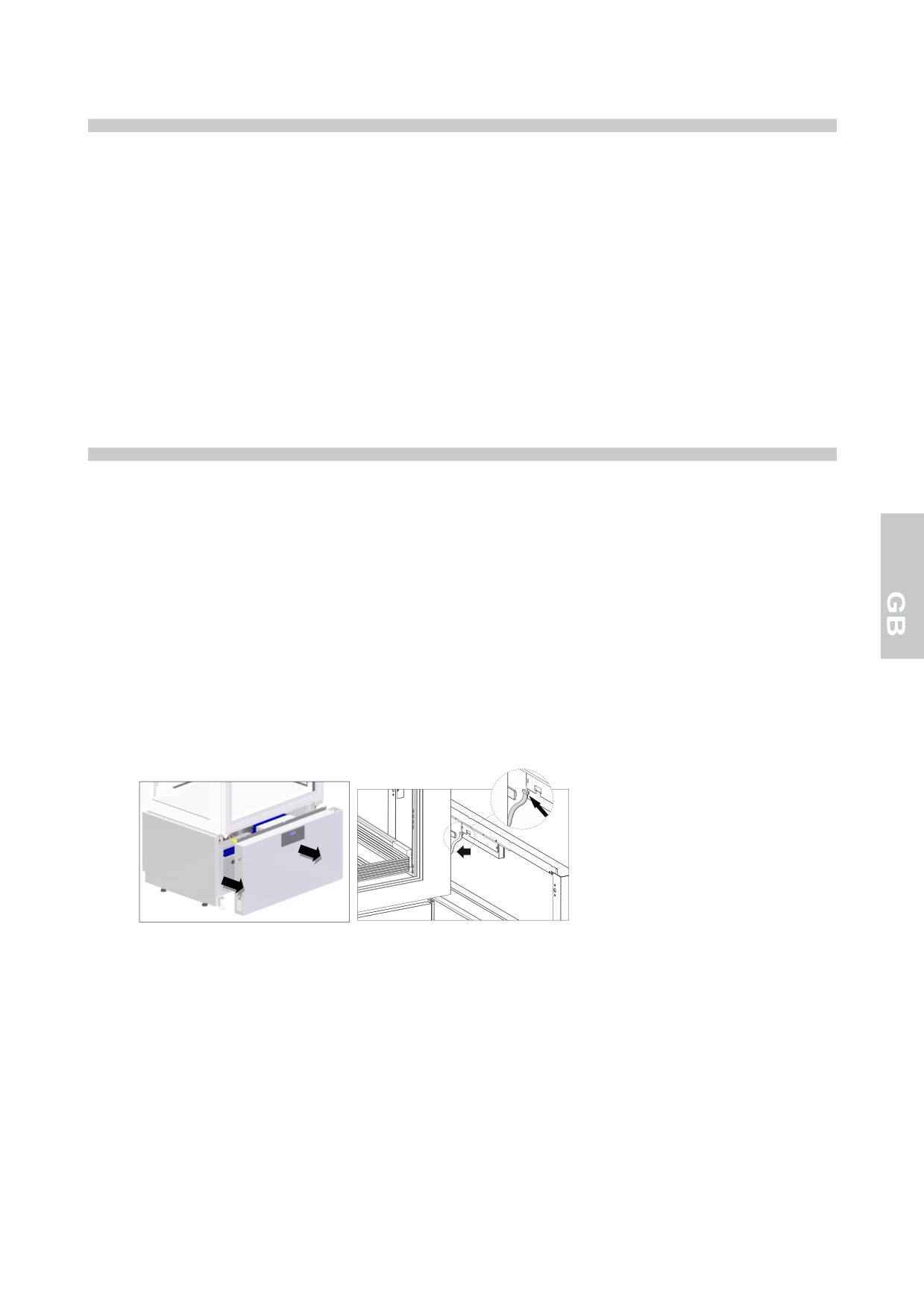
To access the condenser it is necessary to remove the front dashboard:
1. Remove the lower instrument panel, grasping it on the side, freeing it from the four retaining bolts
2. Remove the cable from the panel control board
WARNING: to assure a regular use of the machine it is necessari to clean the copper-alluminium
condensator at least every 30 days.
Accurately clean the condenser in the refrigerating unit and the inner evaporator with either a vacuum
cleaner, a bristle brush or a non-wire brush after removing the protections.
The cleaning and mantainance operations have now come to end.
21
USEFULL ADVICES FOR THE CARE OF THE STAINLESS STEEL
For the cleaning and mantainance of the parts of stainless steel follow the advices written below, bearing in
mind that the first and fundamental rule is to guarantee the non toxicity and best hygiene of the dealed
products.
The stainless steel has a thin oxide coat that prevents rust formation.
But there are substances or detergents that can destroy this coat and give origin to corrosions.
Before using any detergent product ask always your dealer about which neutral detergent is the most
qualified and does not cause corrosions on the steel.
In case of scratches on the surfaces it is necessary to smooth them using thin STAINLESS STEEL wool or
an abrasive sponge in synthetic fibrous material, wiping in the direction of the satin
WARNING: for the cleaning of the STAINLESS STEEL never use iron wool and never let them rest on the
surfaces because little iron deposits could remain on the surfaces and cause rust formations by
contamination and endanger the hygiene.
USAGE INTERRUPTIONS
In case of longer inactivity of the refrigerator and for maintaining it in the best state act as following:
- set the general cut-out in OFF position.
- remove the plug from the socket.
- empty the refrigerator and clean it as described In the chapter "CLEANING".
- let the door open to avold the forming of bad smell.
MALFUNCTIONING
Malfunctioning during operation is often due to banal causes , whitch may nearly all be resolved without the
help of a specialised technician. Consequently, before getting in touch with a service centre, check the
following:
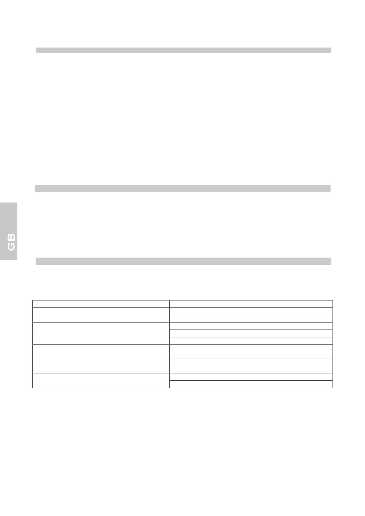
PROBLEM
POSSIBLE CAUSES
The appliance does not start
Check that the plug is properly inserted into the socket.
Check that there is voltage at the socket
The internal temperature is too high
Check the electronic card adjustment
Check for a heat source in the vicinity
Check that the door closes properly
The appliance is excessively noisy
Check that the appliance is standing level. A lopsided
appliance could set off vibrations
Check that the appliance is not touching other appliances
or parts which could resonate
Some condensation is produced on the
Room humidity is very high
appliance
The door is not closed properly
Upon completion of the above checks, if the fault persists, contact an authorised service centre. Always
indicate:
• the nature of the fault
• the model and the serial number of the unit can be found on the electrical specifications plaque, located
on the unit’s instrument panel.
22
WASTE DISPOSAL AND DEMOLITION
WASTE STORAGE
At the end of the product life, avoid release to the environment. The doors should be removed before
disposal.
Temporary storage of special waste is permitted while waiting for disposal by treatment and/or final
collection. Dispose of special waste in accordance with the laws in force with regard to protection of the
environment in the country of the user.
PROCEDURE FOR ROUGH DISMANTLING THE APPLIANCE
All couintries have different legislation; provision laid down by the laws and the authorised bodies of the
countries where the demolition takes place are therefore to be observed.
A general rule is to deliver the appliance to specialised collection and demolition centres. Dismantle the
refrigerator grouping together the components according to their chemical nature. The compressor contains
lubricating oil and refrigerant, which may be recycled. The refrigerator components are considered special
waste, which can be assimilated with domestic waste.
Make the appliance totally unusable by removing the power cable and any door locking mechanisms in order
to avoid the risk of anyone being trapped inside.
DISMANTLING OPERATIONS SHOULD BE CARRIED OUT BY QUALIFIED PERSONNEL.
THE SAFE DISPOSAL OF WASTE FROM ELECTRICAL AND ELECTRONIC EQUIPMENT (WEEE
DIRECTIVE 2002/96/EC)
Do not dump pollutant material in the environment. Dispose of it in compliance with the relevant laws.
Under the WEEE (Waste Electrical and Electronic Equipment) Directive 2002/96/EC, when scrapping
equipment the user must dispose of it at the specific authorised disposal centres, or reconsign it, still
installed, to the original seller on purchase of new equipment.
All equipment which must be disposed of in accordance with the WEEE Directive 2002/96/EC is marked with
a special symbol
The improper disposal of Waste Electrical and Electronic Equipment is liable to punishment under
the relevant laws in the countries where the offence is committed.
Waste electrical and Electronic Equipment may contain hazardous substances with potential harmful
effects on the environment and human health. You are urged to dispose of them properly.
REFRIGERANT MATERIAL SAFETY DATA SHEET
1) R404A: fluid components
• trifluoroethane
(HFC 143a)
52%
• pentafluoroethane
(HFC 125)
44%
• tetrafluoroethane
(HFC 134a)
4%
GWP = 3922
ODP = 0
R452A: fluid components
• pentafluoroethane (HFC 125) 59%
• tetrafluoropropene (HFC 1234yf) 30%
• difluoromethane (HFC 32) 11%
GWP = 2141
ODP = 0
❖ Hazard identification
Overexposure through inhalation may cause anaesthetic effects. Acute overexposure may cause cardiac
rhythm disorders and sudden death. Product mists or sprays may cause ice burns of eyes and skin.
23
❖ First aid procedures
• Inhalation:
keep injured person away from exposure, warm and relaxed. Use oxygen, if necessary. Give artificial
respiration if respiration has stopped or is about to stop. In case of cardiac arrest give external cardiac
massage. Seek immediate medical attention.
• Skin:
use water to remove ice from affected areas. Remove contaminated clothes.
CAUTION: clothes may adhere to skin in case of ice burns.
In case of contact with skin, wash with copious quantities of lukewarm water. In case of symptoms
(irritation or blisters) seek medical attention.
• Eyes:
immediately wash with ocular solution or fresh water, keeping eyelids open for at least 10 minutes. Seek
medical attention.
• Ingestion:
it can cause vomit.. If conscious, rinse mouth with water and drink 200-300 ml of water. Seek medical
attention.
• Other medical treatment:
symptomatic treatment and support therapy when indicated. Do not administer adrenaline or
sympatheticomimetic drugs after exposure, due to the risk of arrhythmia and possible cardiac arrest.
❖ Environmental data
Persistence and degradation
• HFC 143a:
slow decomposition in lower atmosphere (troposphere). Duration in atmosphere is 55 years.
• HFC 125:
slow decomposition in lower atmosphere (troposphere). Duration in atmosphere is 40 years.
• HFC 134a:
si decompone con relativa rapidità nell’atmosfera inferiore (troposfera). La durata nell’atmosfera è 15,6
anni.
• HFCs 143a, 125, 134a:
does not affect photochemical smog
(not included in volatile organic components
- VOC - as
established in the UNECE agreement). Does not cause ozone rarefaction.
Product exhausts released in the atmosphere do not cause long-term water contamination.
2) R290
GWP = 3
ODP = 0
❖ Hazards identification
Liquefied gas - Extremely flammable
❖ First aid measures
• Inhalation:
In high concentrations may cause asphyxiation. Symptoms may include loss of mobility and/or
consciousness. Victims may not be aware of asphyxiation. In low concentrations, may cause narcotic
effects. Symptoms may include dizziness, headache, nausea and loss of coordination. Remove victim to
an uncontaminated area wearing self contained breathing apparatus. Keep the patient relaxed and warm.
Call a physician. Apply artificial respiration if breathing stops..
• Contact with skin and eyes:
In case of spillage, rinse thoroughly with water for at least 15 minutes
• Ingestion:
Route of exposure unlikely
❖ Ecological information
No known ecological damage caused by this product
24
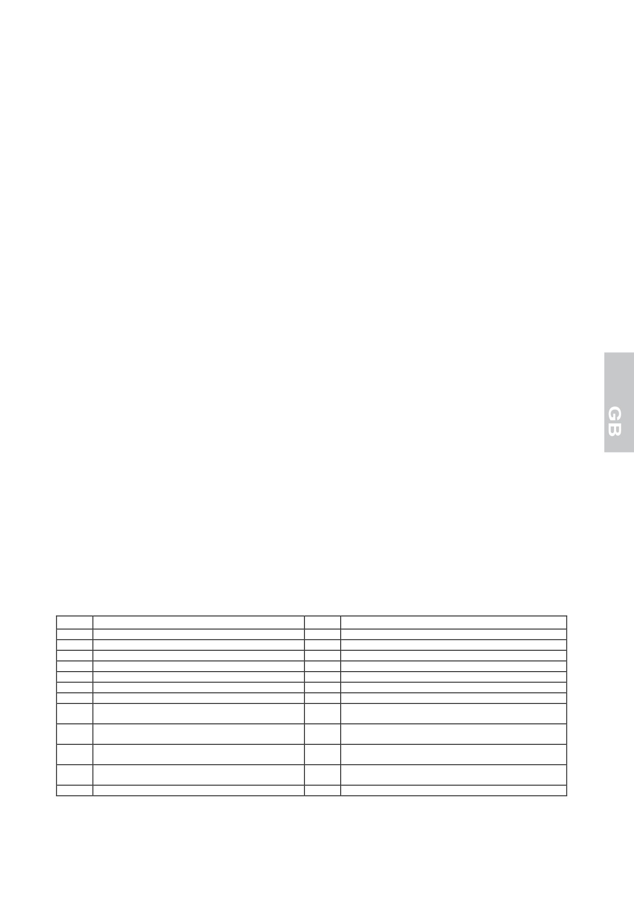
The instruction handbook contains a wiring diagram on the last page
POS
DESCRIPTION
POS
DESCRIPTION
1
COMPRESSOR
44
RELAY COMPRESSOR
2
COMPRESSOR FAN
69
GROUNDING TERMINAL
3
GENERAL TERMINAL BOARD
70
COLD DELIVERY SOLENOID VALVE
8
PLUG
70A
WARM DELIVERY SOLENOID VALVE
9
EVAPORATOR FUN
76
MAGNETIC MICRO-SVWITCH
12
SOLENOID VALVE DEFROSTING
103
HUMIDITY SENSOR
20
DOOR ANTICONDENSING RESISTOR
119
TN DISPLAY CASE ELECTRONIC DATA CARD
20A
SIDE GLASS ANTICONDESATION RESISTANCE
120
BT DISPLAY CASE ELECTRONIC DATA CARD
HEATER
SIDE GLASS ANTICONDESATION RESISTANCE
121
LED SWITCHING POWER SUPPLY
20B
HEATER
REAR GLASS ANTICONDESATION RESISTANCE
122
LED LAMPS
20C
HEATER
SECTION ANTICONDENSATION RESISTANCE
125
ELECTRONIC DATA CARD PRALINERY DISPLAY
20D
HEATER
CASE
22
RESISTANCE FOUND BASIN
25
INDICE
DESCRIPTION DE LA MAQUINA
2
ETIQUETA DE IDENTIFICATION
2
NOTAS GENERALES PARA LA ENTREGA
2
NORMAS DE SEGURIDAD
3
COLOCACION EN SU LUGAR E INSTALACION
4
CARACTERISTICAS TECNICAS
8
TABLEROS DE MANDO
9
PROGRAMACIÓN / MODIFICACIÓN DEL SETPOINT DE TEMPERATURA
10
SMART FUNCTIONS - Funcionalidad de encendido veloz
10
BLOQUEO TECLADO
10
IMPRIME MANUALMENTE LECTURAS DE SONDAS
11
CONFIGURACIÓN PARÁMETROS
11
CONFIGURACIÓN PARÁMETROS - LECTURA SONDAS
16
RESTABLECER PARÁMETROS DE FÁBRICA
16
ALARMAS
16
DESCARCHE
20
PARADA
21
ANORMALIDADES DE FUNCIONAMIENTO
21
LIMPIEZA DIARIA
21
LIMPIEZA Y MANUTENCION GENERAL
22
CONSEJOS UTILES PARA LA MANUTENCION DEL ACERO INOXIDABLE
22
INTERRUPCIONES EN EL FUNCIONAMIENTO
23
PROBLEMAS DE FUNCIONAMIENTO
23
DESPACHO DE RESIDUOS Y DEMOLICION
23
FICHA TÉCNICA DEL REFRIGERANTE
24
1
DESCRIPTION DE LA MAQUINA
Estos equipos se han diseñado para la exposición y la conservación temporal de los alimentos. Cualquier
otro uso tiene que considerarse inadecuado.
ATENCION: las máquinas no son idóneas para ser instaladas al aire libre y/o en ambientes sometidos a
acciones de agentes atmosféricos.
El fabricante declina toda responsabilidad por usos no previstos.
También cuentan con un evaporador de aletas protegido contra el óxido, un compresor hermético, un
condensador en cobre-aluminio y una tarjeta digital electrónica. El equipo tiene estantes removibles,
excepto para el modelo Heladería 25-15ºC que son fijas.
En los grupos refrigerantes se usa fluido refrigerante permitido por las legislaciones actuales del tipo HFC.
ETIQUETA DE IDENTIFICATION
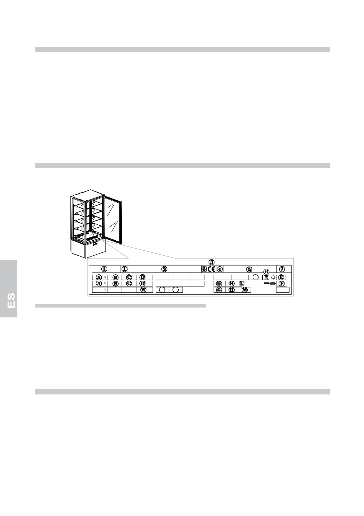
Ante cualquier comunicación con el constructor citar siempre el MODELO y el NUMERO DE MATRICULA
de la máquina colocada sobre la placa características técnicas.
Z
Y
Z
Contenido del campo eléctrico de la tarjeta tecnica de el aparato
1) MODELO
D) POTENCIA NOMINAL
2) EMPRESA DE CONSTRUCCION
E) POTENCIA TOTAL
3) SIGLA MARCA CEE
F) CORRIENTE DE EL FUSIBILE
4) ANO DE CONSTRUCCION
G) TIPO DE GAS DE EL REFRIGERANTE
5) NUMERO DE MATRICULA
H) CANTIDAD DE EL GAS REFRIGERANTE
6) CLASE DE AISLAMIENTO ELECTRICO
L) TIPO DE TEMPERATURA DE LA INSTALLACION
7) CLASE DE PROTECCION ELECTRICA
DEL FRIGORIFICO
A) VOLTAJE DE ALIMENTACION ELECTRICA
R) SÍMBOLO RAEE
B) INTENSIDAD DE LA CORRIENTE ELECTRICA
W) POTENCIA DE LOS ELEMENTOS DE CALEFACCION
C) FRECUENCIA DE LA ALIMENTACION ELECTRICA
NOTAS GENERALES PARA LA ENTREGA
Cuando se recibe el bulto, controlar que el embalaje esté intacto y que no haya sufrido daños durante el transporte.
Después que desembale el equipo compruebe que todas las partes o componentes, así como las
características y su estado correspondan a las especificaciones ordenadas por usted al hacer el pedido.
Si así no fuera, ponerse en contacto inmediatamente con el vendedor.
Además de felicitarlo por haber hecho una gran elección, esperamos que pueda utilizar de la mejor manera
nuestros equipos siguiendo las instrucciones y las precauciones que contiene el presente manual.
Pero recordad que está prohibida la reproducción del presente manual y que, debido a una constante
búsqueda de innovación y calidad tecnológica, las características aquí presentes podrían cambiar sin preaviso.
2
NORMAS DE SEGURIDAD
ATENCION: antes de cualquier operación de manutención o limpieza, es necessario aislar el equipo de la
red eléctrica:
- oner el interruptor general en posición OFF;
- desenchufar el equipo;
ATENCION: no utilizar tomacorrientes o enchufes desprovistos de puesta a tierra.
El tomacorrientes de la red eléctrica debe tener su CABLE DE TIERRA.
ATENCION: para enchufar en la red, no utilizar adaptadores o prolongadores de cable.
ATENCION: esperar el tiempo necesario para alcanzar la temperatura determinada antes de poner adentro
los alimentos a conservar.
ATENCION: no introduzca en el equipo bebidas o alimentos calientes.
ATENCION: proceda al almacenamiento de los productos de conservación, sin rebosar los estantes y sin
obstaculizar la circulación del aire.
ATENCION: no realice la limpieza de las partes vecinas del equipo cuando la puerta esté abierta.
No lave el équipo con chorros de agua directa y a alta presiòn.
ATENCION: no usar sustancias a base de cloro (lejía, ácido muriático, etc.) o que sean tóxicas para la
limpieza o estén cerca de los equipos.
3
ATENCION: no apoye objetos en el fondo del equipo. Use para ello los respectivos estantes.
Los estantes soportan un peso máximo de 12 kg.
ATENCION: iesgo de rotura de los vidrios. Cierre o abra la puerta SUAVEMENTE, NUNCA CON
VIOLENCIA y no se apoye sobre la puerta.
La limpieza y la manutención de la instalación refrigeradora y de la zona compresores requiere la intervención
de un técnico especializado y autorizado; por lo tanto no pueden ser efectuadas por personal no preparado.
Para intervenciones de manutención o en caso de anormalidades, desenchufar completamente el equipo y solicitar
la intervención del SERVICIO DE ASISTENCIA a un centro autorizado y el empleo de repuestos originales.
El incumplimiento de las disposiciones anteriores pone en riesgo el estado de seguridad de los equipos.
COLOCACION EN SU LUGAR E INSTALACION
Los equipos se envían sobre paletas y protegidos con cajas de cartón.
Cuando se reciben y después de haberlas desembalado, en caso de daños o falta de partes, seguir las
instrucciones del capítulo "NOTAS GENERALES PARA LA ENTREGA".
Las operaciones de puesta en marcha y de instalaciòn deben ser efectuadas por personas especializadas.
ATENCION: los elementos del embalaje (las bolsas de àstica, il poliéster, los clavos, etc) no deben dejarse
al alcanze de los ninos porque pueden ser causa de peligros.
Con un carro de horquilla suba el equipo y llévelo hasta el lugar de instalación, poniendo atención que la
carga no esté desequilibrada.
ATENCION: riesgo de volcado. Nunca incline el equipo. Durante el movimiento manténgalo sostenido con la
ayuda de personal idóneo.
ATENCION: nunca lo transporte en posición horizontal porque podría causar daños a las estructuras y a las
instalaciones.
Una vez en el lugar de instalación siga las siguientes instrucciones.
Retirar la caja de embalaje, la cinta adhesiva y los elementos de poliestireno presentes.
Retirar la placas detrás del aparato.
4
Quitar los listones A, B y C de la base del embalaje, retirando primero los tornillos de fijación.
C
A
B
Poner los listones A debajo de las ruedas del aparato.
A
A
Posicionar los listones B y C delante de la base de embalaje y fijarlos a ella.
B
C
C
B
Deslizar con mucho cuidado la vitrina hasta el suelo.
Colocar el aparato en su posición definitiva.
Regular las patas dispuestas bajo el aparato de modo que no se mueva.
5
ATENCION: Coloque el equipo al menos 10 cm de la pared posterior. Puede desplegar los equipos, pero en
cada caso debe dejar un espacio de más o menos 5 cm entre un equipo y el otro.
min.
10 cm
min.
5 cm
min.
5 cm
ATENCION: Asegúrese que el equipo no esté expuesto a los rayos del sol ni cerca a otras fuentes de calor
o a ambientes con altas temperaturas, porque podría causar un bajo rendimiento y un desgaste mayor del
normal.
Los aparatos son declarados en clase climática 4 ( T = 30°C U.R. = 55%)
Remover la pelicula protectiva de el producto.
Esta operación puede provocar un choque leéctrico, aunque no sea peligroso (electricidad estática).
El inconveniente se puede reducir o eliminar manteniendo una mano siempre en contacto con el aparato o
colegando a tierra el embalaje exterior.
Extraer suavemente los estantes evitando cualquier daño.
Limpie el equipo y los estantes en la
forma indicada en el capítulo “LIMPIEZA”. Después que haya limpiado,
deje abierta la puerta
por lo menos 72 horas sin ponerlo a funcionar.
Para poner
los estantes proceda de la siguiente manera:
• Inicie por el primer
estante inferior, agárrelo por la parte central con ambas manos.
• Coloque los
ganchos de acero en las ranuras de las cremalleras teniendo el estante ligeramente
inclinado hacia lo
alto.
6
• Baje el estante y
colóquelo
en posición horizontal, asegurándose que el gancho inferior se
introduzca en la
espiga de la ranura inferior de la cremallera.
ATENCIÓN: el cumplimiento de esta indicación es muy importante para garantizar la buena
estabilidad del estante.
• Para desenganchar el estante siga las indicaciones anteriores pero en forma contraria.
Los equipos está compuesto por un enchufe del tipo SHUKO. Comprobar la correspondencia de la misma
con las normas EN60320 y a las normas nacionales. Sustituir el enchufe con uno en la norma en el caso
que no tuaviese que corresponder.
ATENCION: La operación deve ser efectuada por un técnico especializado.
Compruebe que la tensión de la red corresponda a la que está reportada en la placa con las características
técnicas del equipo.
Enchufar el aparato en el tomacorriente.
A este punto han terminado las operaciones de colocación en su lugar del equipo e instalación.
7
CARACTERISTICAS TECNICAS
Las dimensiones de los equipos se encuentran a continuación.
8
TABLEROS DE MANDO
Todos los equipos manejan el siguiente panel de mandos:
5
6
7
POS
DESCRIPCIÓN
1
Tecla ON/SBY/ENTER
2
Tecla DOWN
3
Tecla UP
4
Tecla LEDS
5
PICTOGRAMA DESCARCHE
6
PICTOGRAMA VENTILADOR
7
PICTOGRAMA COMPRESOR
1
2
3
4
Tecla ON/SBY/ENTER
Apretando y soltando permite verificar/ modificar el setpoint de temperatura
del aparato.
Apretando durante 3 segundos, soltando en el momento de la aparición,
sobre el display de la label [Sby], lleva el aparato a stand by.
Con instrumento en stand by [en el display aparece Sby] apretando el
controlador se enciende.
Teclas UP y DOWN
Permiten aumentar o disminuir el valor del parámetro que se quiere
modificar.
Pulsándolos permiten visualizar las temperaturas de mínima y máxima
registradas (si disponibles) y eventualmente alarmas activadas.
Presionando simultáneamente deshabilita el bloqueo del teclado.
La tecla UP presionada por más de 3 segundos activa la descongelación
manual
La tecla DOMN presionada por más de 3 segundos permite modificar la
configuración de la humedad de la celda.
TECLA LEDS
Presionado permite la activación o la desactivación de la iluminación.
APPAREILS +14 °C / +16 °C
Presionado por un lapso de tiempo superior a los 3 segundos permite
visualizar temporalmente por 5 segundos en modalidad fija la lectura de la
sonda de humedad.
PICTOGRAMA DESCARCHE
Led encendido: descarche en marcha
Led centelleante: retraso activación descarche o goteo en marcha
Led centelleante a frecuencia elevada: alarma registrado en memoria
ICONA VENTOLA
Led encendido: ventiladores cámara en función
Led parpadeante: demora activación ventiladores
PICTOGRAMA COMPRESOR
Led encendido: compresor en función
Led centelleante: retraso activación compresor
9
PROGRAMACIÓN / MODIFICACIÓN DEL SETPOINT DE TEMPERATURA
Apretar y soltar la tecla on/sby/enter: el display muestra en modalidad
centelleante el setpoint corriente durante 5 segundos.
Transcurrido dicho tiempo el display vuelve a indicar la temperatura en
cámara
Durante el centelleo del display utilizar las teclas up y down para aumentar o
disminuir el setpoint de temperatura deseado
Presionar nuevamente la tecla on/sby/enter para confirmar el nuevo setpoint
SMART FUNCTIONS - Funcionalidad de encendido veloz
DESCARCHE MANUAL FORZADO
Presionar la tecla up por más de 3 segundos para acceder a la función de
descongelación manual.
MODIFICA LA HUMEDAD RELATIVA +2°C/+10°C y -22°C/+5°C
Presionar la tecla down por más de 3 segundos para modificar el porcentaje
de humedad relativa en la celda.
A la etiqueta led de parpadeo temporáneo [F_C] corresponde una menor
humedad relativa (mitras en paralelo al compresor).
A la etiqueta led de parpadeo temporánea [F__] corresponde una mayor
humedad relativa (mitras independientes).
El label parpadeante de confirmación [FtE] corresponde a la humedad
relativa prevista por el fabricante.
MODIFICA LA HUMEDAD RELATIVA +14°C/+16°C
Presionar el pulsante down por un lapso de tiempo superior a 3 segundos: el
display visualiza en modalidad parpadeante el setpoint de humedad corriente
por 5 segundos.
Transcurrido este tiempo el display regresa a indicar la temperatura en la
cámara.
Durante el parpadeo del display utilizar los pulsantes
para aumentar o
disminuir el setpoint de humedad deseado.
Presionar el pulsante on/sby/enter para confirmar el nuevo setpoint: la
adquisición del nuevo valor viene indicada con una señal acústica de 3 beep
breves y consecutivos.
Después de 2 segundos el display vuelve a visualizar la temperatura de la
cámara.
BLOQUEO TECLADO
Presionar simultáneamente las teclas up e down por más de 3 segundos.
Se visualiza la etiqueta led [Loc].
10
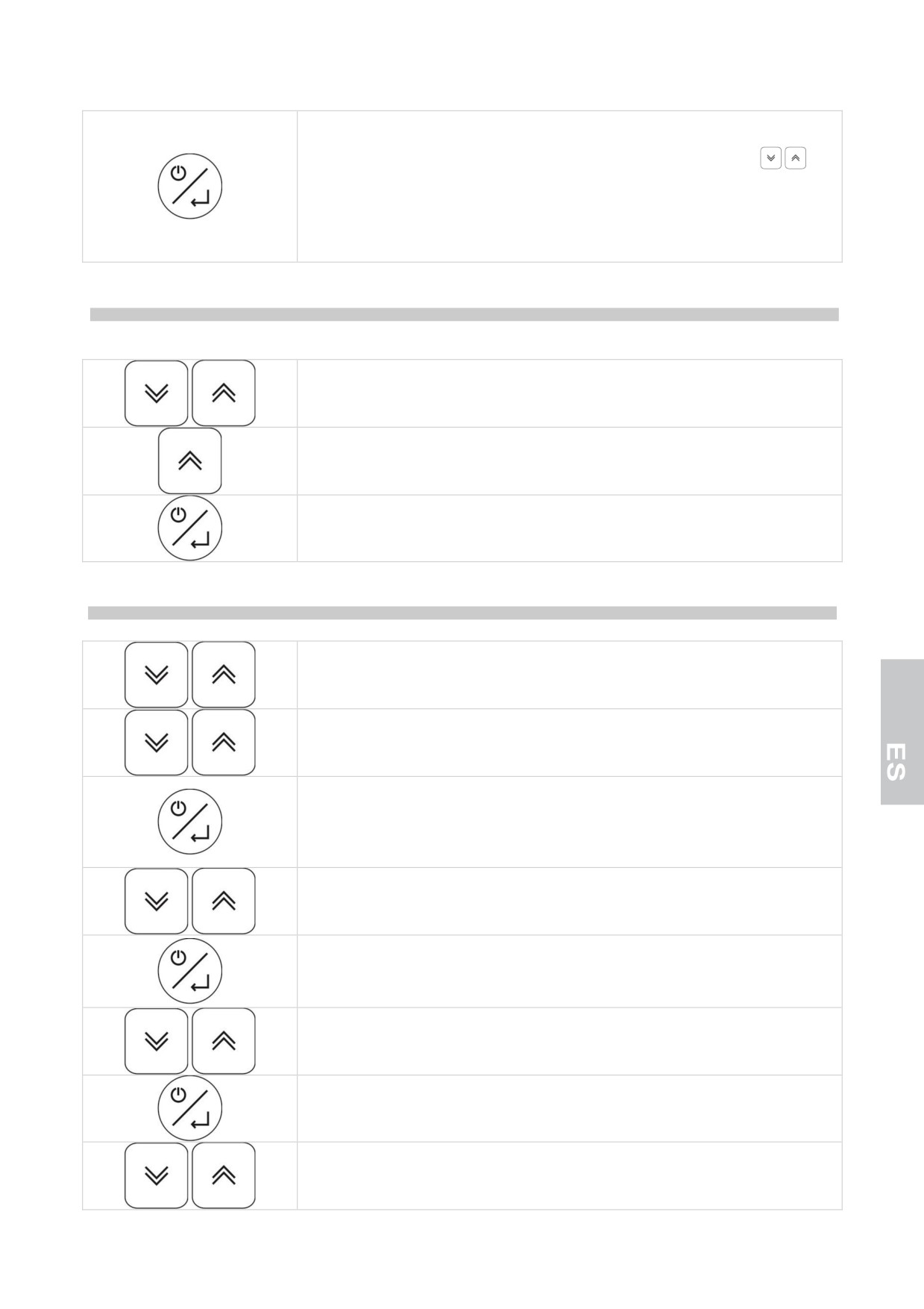
Presionar la tecla on/sby/enter para confirmar la selección y activar la función.
Después de 30 segundos se sale de la función si no es confirmada.
Para desbloquear el teclado presione simultáneamente las teclas
por
más de 5 segundos: confirmando esta operación en el display aparece [UnL]
parpadeante.
Con el teclado bloqueado presione cualquier tecla y aparecerá en el display
la etiqueta led [Loc].
IMPRIME MANUALMENTE LECTURAS DE SONDAS: junto al terminal de impresión TSP
(sólo para equipos 25°C/-15°C y -22°C/+5°C)
Presionar simultáneamente las teclas up e down por más de 3 segundos.
Se visualiza la etiqueta led [Loc].
Use la tecla up para visualizar la función [Prt].
Presionar la tecla on/sby/enter para confirmar la selección y activar la función.
Después de 30 segundos se sale de la función si no es confirmada.
CONFIGURACIÓN PARÁMETROS
Presionar simultáneamente las teclas up e down por más de 3 segundos.
Se visualiza la etiqueta led [Loc].
Utilizar las teclas up y down para leer la función [PAr].
Presionar la tecla on/sby/enter para confirmar la selección y activar la función.
Después de 30 segundos se sale de la función si no es confirmada.
Piden la password de encendido.
El display se prepara para la introducción de la password, se lee [00]
Utilizar las teclas up y down para seleccionar la password “65”
Apretar la tecla on/sby/enter para confirmar la elección.
Si la password insertada es correcta se lee el primer parámetro de la lista de
configuración.
Utilizar las teclas up y down para hojear todos los parámetros del controlador
Apretar la tecla on/sby/enter para confirmar la elección.
Utilizar las teclas up y down para seleccionar el nuevo valor del parámetro
11
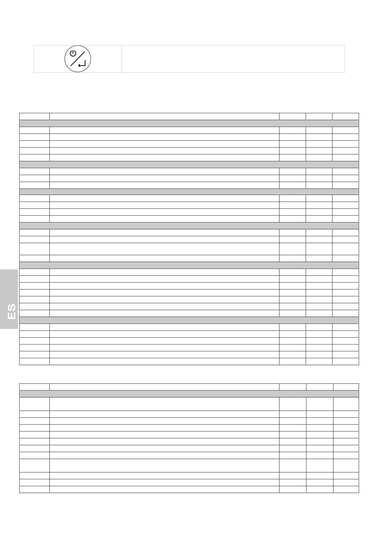
Apretar la tecla on/sby/enter para confirmar la elección.
PARAMETROS DE CONFIGURACION
“EQUIPOS +2°C/+10°C”
Parámetro
Descripción
Default
min
MAX
INGRESOS A MEDIDA
/1
calibración sonda cámara (el parámetro está expresado en octavos de grado)
0°C
-40
+99
/6
configuración ingreso digital (0= contacto abierto, 1= contacto cerrado)
1
0
1
/7
tiempo de retraso por alarma puerta abierta (0= excluido)
120 sec
0
240
Pr
lectura sonda cámara
- °C
-
-
Pc
lectura sonda condensador
- °C
-
-
REGULACIÓN COMPRESOR
r0
histéresis regulador (diferencial)
+4°C
1
15
r1
mínimo setpoint de trabajo programable
+2°C
-40
r2
r2
máximo setpoint de trabajo programable
+10°C
r1
+99
PROTECCIÓN COMPRESOR
C0
retraso activación compresor en el momento del encendido instrumento
1 min
0
240
C2
tiempo mín. de retraso entre el apagado del compr. y el sucesivo encendido
3 min
0
240
C5
tiempo de ciclo encendido compresor en caso de alarma sonda cámara
10 min
1
240
C6
% de C5 en el cual el compr. se enciende en caso de alarma sonda cámara
50 %
0
100
DESCARCHE
d0
intervalo de descarche (0 = excluido)
6 horas
0
99
d3
duración máxima descarche (0 = el desc. no se activa nunca)
20 min
0
99
d6
Visualización del display en descongelación
1
0
2
(0 = temperatura celda efectiva, 1 = temperatura celda bloqueada, 2 = label dEF)
dE
tipo de cuenta interv. de descarche:
0 = horas reales; 1 = horas ON comp.; 2 = autodeterm.
0
0
1
ALARMAS
A0
histéresis de la alarma (diferencial)
+2 °C
1
15
A1
alarma de mínima relativa al setpoint de trabajo (0 = excluido)
-2 °C
-40
0
A2
alarma de máxima relativa al setpoint de trabajo (0 = excluido)
+15 °C
0
+99
A3
tiempo de exclusión de la alarma desde el encendido del instrumento
120 min
0
240
A4
modalidad activación buzzer para alarma: 0 = siempre; 1 = temporizado
1
0
1
A5
tiempo límite para aviso acústico del buzzer en alarma (sólo si A4 = 1)
1 min
0
240
A6
tiempo de exclusión de la alarma de temperatura (sólo si A1 y/o A2 0)
15 min
0
240
REGULACIÓN VENTILADORES EVAPORADOR
F3
func. vent. evap. durante norm. func. (0=OFF, 1=ON, 2=paralelo al compr.)
1
0
2
F6
temperatura por debajo de la cual el ventilador condensador se apaga
20°C
-40
+99
F7
diferencial ventiladores condensador (relativo a F6)
+3°C
1
25
F8
func. vent. cond. durante normal func. (0=paral. al compr., 1=ON); ver también F6 y F7
0
0
1
FA
temperatura crítica para indicación de alta temperatura de condensación
46°C
-40
+99
Fb
temperatura crítica para alarma de alta presión
49°C
-40
+99
“EQUIPOS -25°C/-15°C”
Parámetro
Descripción
Default
min
MAX
INGRESOS A MEDIDA
/1
calibración sonda cámara (el parámetro está expresado en octavos de grado)
-16
-40
+99
(ottavi °C)
/2
habilitación sonda evaporador (0=ausente, 1=presente)
0
0
1
/3
habilitación sonda condensador (0=ausente, 1=presente)
1
0
1
/6
configuración ingreso digital (0= contacto abierto, 1= contacto cerrado)
0
0
1
/7
tiempo de retraso por alarma puerta abierta (0= excluido)
120 s
0
240
/A
setpoint activación resistencia puerta (sólo si /9 = 0)
-7 °C
-40
+99
/b
histéresis regulación activación resistencia puerta (sólo si /9 = 0)
2 °C
1
15
/E
control visualización lectura sonda celda (0= normal, 1=limitación superior a r0)
1
0
1
/F
gestión de descongelación del relé de descongelación (0 = desactivado cuando se alcanza el valor
0
0
1
establecido con d2 en el evaporador, 1 = desactivado al final del tiempo d7)
Pr
lectura sonda cámara
- °C
-
-
Pd
lectura sonda evaporador/descarche
- °C
-
-
Pc
lectura sonda condensador
- °C
-
-
12
REGULACIÓN COMPRESOR
r0
histéresis regulador (diferencial)
+2 °C
1
15
r1
mínimo setpoint de trabajo programable
-25 °C
-40
r2
r2
máximo setpoint de trabajo programable
-15 °C
r1
+99
PROTECCIÓN COMPRESOR
C0
retraso activación compresor en el momento del encendido instrumento
1 min
0
240
C2
tiempo mín. de retraso entre el apagado del compr. y el sucesivo encendido
3 min
0
240
C5
tiempo de ciclo encendido compresor en caso de alarma sonda cámara
10 min
1
240
C6
% de C5 en el cual el compr. se enciende en caso de alarma sonda cámara
70 %
0
100
DESCARCHE
d0
intervalo de descarche (0 = excluido)
0 horas
0
99
d1
tipo de descarche (0 = a resistencias, 1 = a gas caliente)
0
0
1
d2
temper. fin descarche (referida a la temper. del evaporador)
+12 °C
-40
+99
d3
duración máxima descarche (0 = el desescarche posee una corta duración ; 255 = el desescarche
255 min
0
255
posee una duración infinita)
d6
Visualización del display en descongelación
1
0
2
(0 = temperatura celda efectiva, 1 = temperatura celda bloqueada, 2 = label dEF)
d7
tiempo de goteo
4 min
0
15
dE
tipo de cuenta interv. de descarche:
0 = horas reales; 1 = horas ON comp.; 2 = autodeterm.
0
0
1
ALARMAS
A0
histéresis de la alarma (diferencial)
+2 °C
1
15
A1
alarma de mínima relativa al setpoint de trabajo (0 = excluido)
-2 °C
-40
0
A2
alarma de máxima relativa al setpoint de trabajo (0 = excluido)
+15 °C
0
+99
A3
tiempo de exclusión de la alarma desde el encendido del instrumento
120 min
0
240
A4
modalidad activación buzzer para alarma: 0 = siempre; 1 = temporizado
1
0
1
A5
tiempo límite para aviso acústico del buzzer en alarma (sólo si A4 = 1)
20 s
0
240
A6
tiempo de exclusión de la alarma de temperatura (sólo si A1 y/o A2 0)
15 min
0
240
A7
tiempo excl. al. de temper. post parada vent. evap. (para A1 y/o A2 0)
60 min
0
240
REGULACIÓN DE LOS VENTILADORES DEL EVAPORADOR Y DEL CONDENSADOR
F1
temper. sobre la cual el vent. evap. se apaga (sólo si /A = 1 y F7 = 3 ó 4)
-1 °C
-40
+99
F2
diferencial ventiladores (relativo a F1, sólo si /A = 1 y F7 = 3 ó 4)
+2 °C
1
15
F3
func. vent. evap. durante norm. func. (0=OFF, 1=ON, 2=paralelo al compr., 3=establecida con F1 y
2
0
4
F2, 4=establecida con F1 y F2 a compr. ON y OFF a comp. OFF
F4
func. vent. evap. en desc. y got. (0= OFF, 1= ON, 2 = estab. con F7)
0
0
2
F5
tiempo parada ventilador evaporador después de goteo
3 min
0
15
F6
temperatura por debajo de la cual el ventilador condensador se apaga
10 °C
-40
+99
F7
diferencial ventiladores condensador (relativo a F6)
+3 °C
1
25
F8
func. vent. cond. durante normal func. (0=paral. al compr., 1=ON); ver también F6 y F7
0
0
1
F9
funcionamiento vent. cond. En descarche y goteo (0=OFF, 1=ON, 2=ON si Tc≥26°C y OFF si
2
0
2
Tc<25°C)
FA
temperatura crítica para indicación de alta temperatura de condensación
46 °C
-40
+99
Fb
temperatura crítica para alarma de condensador sucio
48 °C
-40
+99
Fc
tiempo de permanencia de la sonda del condensador en el valor igual o superior a FA para la
5 min
0
240
activación de la alarma HtC
Fd
tiempo de permanencia de la sonda del condensador en el valor igual o superior a Fb para la
1 min
0
240
activación de la alarma dCA
FE
aumento de temperatura en el valor del punto de ajuste del aparato en caso de alarma dCA
5 °C
1
15
activada
FF
temperatura crítica para alarma de alta presión
55 °C
-40
+99
FH
tiempo límite empleado para pasar del valor FA al valor Fb dentro del cual se activa igualmente la
12 s
0
15
alarma HP
FL
temperatura crítica para señalización de baja temperatura de evaporación
-37 °C
-40
+99
Fn
tiempo de permanencia de la sonda del evaporador en el valor igual o inferior a FL para la
30 min
0
240
activación de la alarma LtE
Fo
tiempo de permanencia de la alarma LtE; al alcanzarse este tiempo, se efectúa un desescarche
30 min
0
240
automático
FP
temperatura crítica para alarma de baja presión
-41 °C
-42
+99
IMPRESION
P0
Habilitar impresión de los parámetros de configuración (0= deshabilitada)
1
0
1
P1
Tiempo de prueba (ver también parámetro P6)
60
1
60
min/horas
P2
Selección de las sondas de temperatura que se desea imprimir (0=ninguna, 1=sonda cámara,
1
0
3
2=sonda cámara y evaporador)
P3
Seleccionar encabezamiento de la boleta de pago (0 =excluso, 1= Vitrina BTV, 2 = Vitrina BTS)
2
0
2
P4
Habilitación de impresión del número del aprato (0 = no, 1= sì)
1
0
1
P5
Seleccionar idioma para encabezamiento de la boleta de pago
1
-1
5
(1 = italiano, 2 = inglés, 3 = francés, 4 = español, 5 = alemán)
P6
Seleccionar unidad de medida para tiempo de prueba
1
1
2
(1 = minutos,
2 = horas)
13