Shantui SD22. Operation and Maintenance Manual - 5
MAINTENANCE | MAINTENNANCE
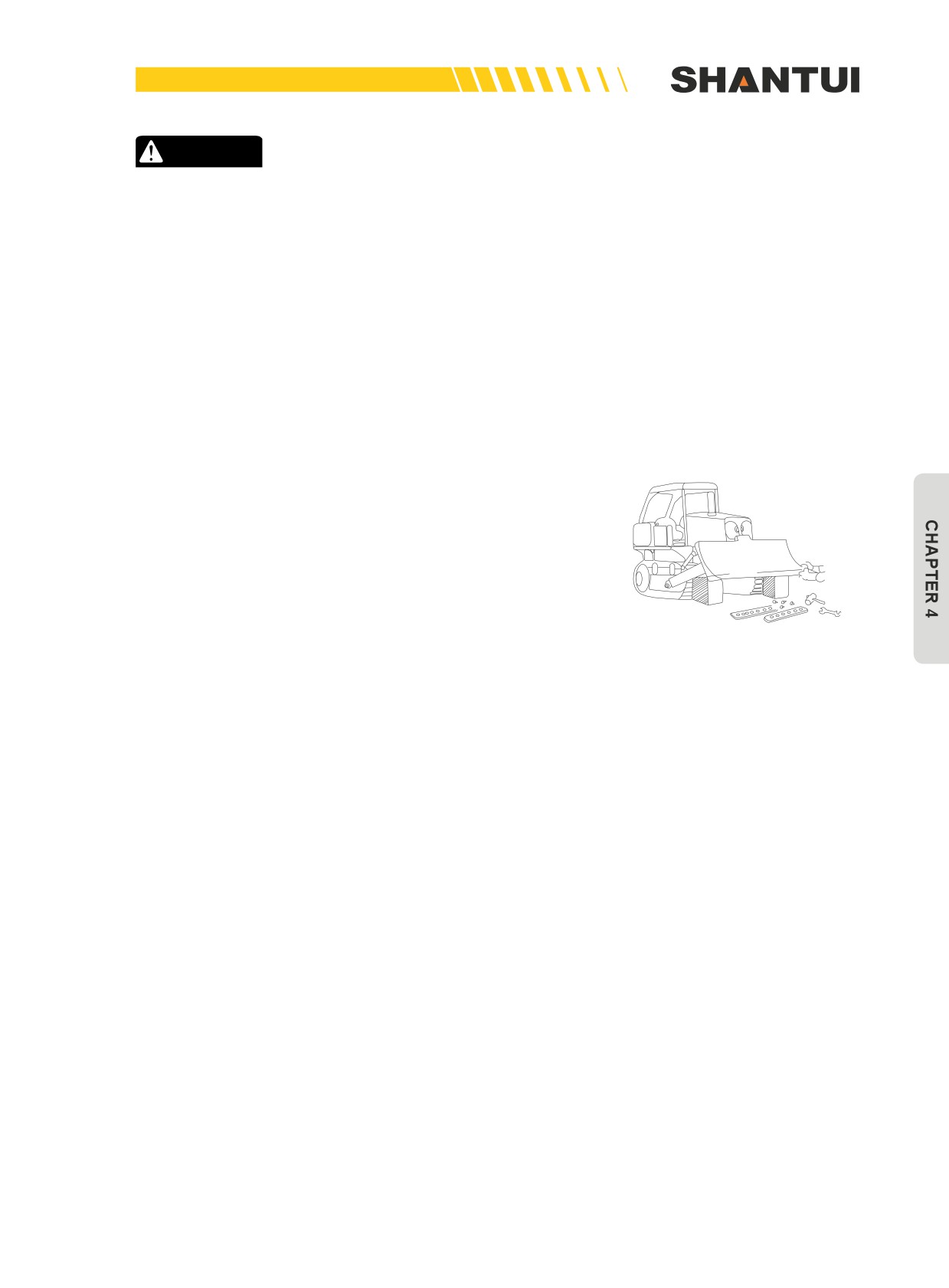
CAUTION
• Do not handle electric systems in rain;
• When checking or cooling water, be careful, as hot water may spurt out to injure people;
• After the engine oil filter or strainer is replaced, exhaust the air from the oil circuit;
• Never add oil by taking out the filter screen of the oil injection port.
Remember that there is high pressure within the hydraulic oil circuit. When you add oil,
drain oil or perform check and maintenance, release the pressure first. The method for re-
leasing pressure is as follows:
• Lower the blade and ripper to ground, extinguish the engine, pull the hydraulic system’s control
lever to each gear position 2-3 times continuously, and then slowly turn loose the oil tank’s cap or
the pipe connector;
• Before changing engine oil, start the vehicle to raise the oil temperature to 30-40°C strain the oil;
• Use clean oil and grease. When checking or changing oil, do not do it in a dusty location, or the
dust can get into the oil;
• Before servicing the gearbox, take all the objects out of your pockets. Be careful, wrenches or
nuts may fall into the box, to create a big trouble;
• Fuel and oil should be kept away from fire;
• Do not use fire to replace lamps for lighting; When changing O-rings, gaskets or other sealing
items, rigorously clean part’s surface, and install them carefully;
• Within the battery box, there is a 24V DC socket, which can be used directly during servicing &
maintenance.
154
MAINTENNANCE | MAINTENANCE
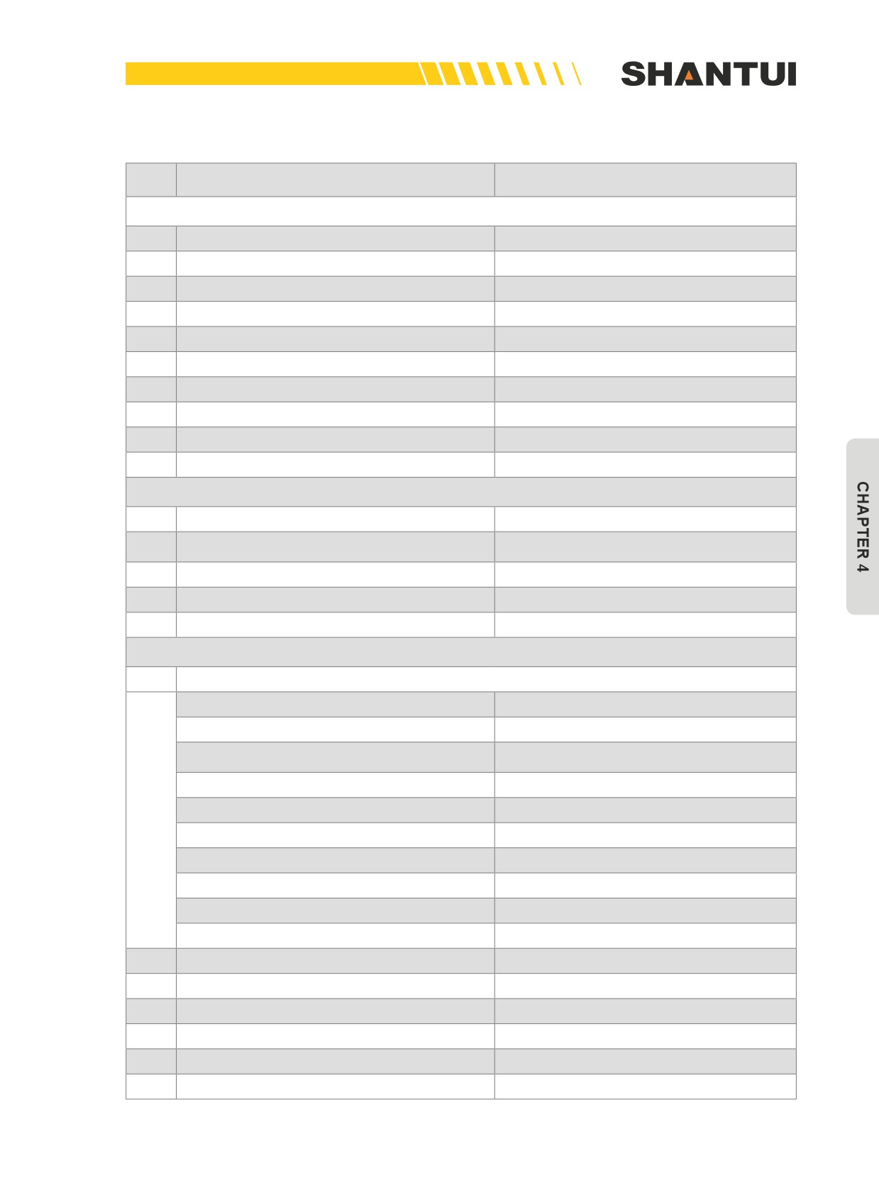
4.1.1 SERVICE TABLE
NO.
MAINTENANCE ITEMS
MAINTENANCE CONTENTS
CHECK BEFORE STARTING
1
Checking oil or water leakage
Checking
2
Checking bolts and nuts
Checking and tightening
3
Checking electric circuits
Checking and tightening
4
Checking coolant water level
Checking and replenishing
5
Checking oil level in engine oil pan
Checking and replenishing
6
Checking fuel level
Checking and replenishing
7
Checking oil level in steering clutch
Checking and replenishing
8
Discharging impurities from fuel tank
Draining water and sediments
9
Checking dust indicator
Checking and cleaning air filter
10
Checking brake pedal travel
Checking and adjusting
INITIAL 250 HOURS SERVICE
1
Fuel filter
Changing the filter’s cartridge
Steering clutch case (including transmission
2
Changing oil and washing the strainer
case and torque converter)
3
Hydraulic tank and filter
Changing oil and Replacing filter element
4
Final drive case
Changing oil
5
Engine valve’s clearance
Checking and adjusting
EVERY 250 HOURS SERVICE
Lubricating (Checking the following areas, lubricating them and applying grease to them)
Fan pulley
1 place
Tension roller and tension roller’s bracket
2 places
1 places of straight tilt blade, and 2 places
Support arm’s screw rod
of angle blade
Oil cylinder bracket shaft
2 places
Oil cylinder bracket yoke
4 places
1
Tilt oil cylinder ball joint
Straight tilt blade: 1 place
Support arm’s spherical hinge
Straight tilt blade: 1 place
Blade arm ball joint
3 places
Oblique arm’s spherical hinge
2 places
Various hinged joints of the ripper
18 places
2
Engine oil pan and filter
Draining oil and replacing the filter element
3
Gearshift’s oil filter and steering oil filter
Replacing filter element
4
Final drive case
Checking oil level and replenishing
5
Hydraulic tank
Checking oil level and replenishing
6
Generator’s driving belt
Adjusting tension
7
Water pump’s driving belt
Adjusting tension
155
MAINTENANCE | MAINTENNANCE
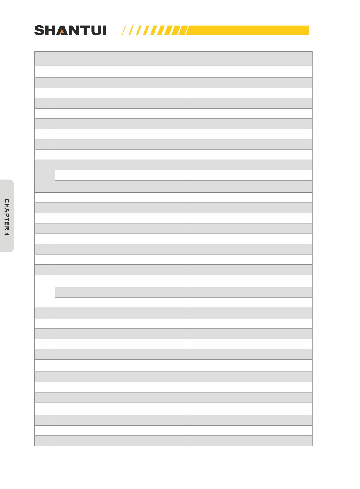
CONTINUED
CHECK BEFORE STARTING
8
Battery electrolyte
Checking level
9
Strainer on the bottom of fuel tank
Washing
EVERY 500 HOURS SERVICE
1
Fuel filter
Replacing filter element
2
Breather
Washing
3
Fan belt
Adjusting tension
EVERY 1000 HOURS SERVICE
Lubricating (Checking the following areas, lubricating them and applying grease to them)
Universal joint
8 places
1
Oblique support arm
2 places
Idler’s tensioning oil cylinder
2 places
2
Water tank’s radiation fin
Checking and cleaning
3
Steering clutch’s case
Changing oil and washing the strainer
4
Final drive case
Changing oil
5
Hydraulic tank and filter
Changing oil and Replacing filter element
6
Walking parts
Checking and lubricating
7
Tubocharger
Checking roller’s clearance
8
Corrosion resistor
Changing the filter’s cartridge
EVERY 2000 HOURS SERVICE
(Checking the following areas, lubricating
Lubricating
them and applying grease to them)
Equalizer bar’s axle
1 places
1
Brake pedal
5 places
2
Breather of the engine’s crankcase
Washing
3
Tubocharger
Washing
4
Valve clearance
Checking and adjusting
5
Engine’s damper
Checking or changing
EVERY 4000 HOURS SERVICE
Checking if the belt is loose and if there is
1
Water pump
water leakage
2
Fan pulley and tension wheel
Checking if it is loose
MAINTENCE WHEN NEEDED
1
Air cleaner
Cleaning and changing
Washing the inside and changing the cool-
2
Coolant system
ant
3
Track tension
Checking and adjusting
4
Track bolt
Checking and tightening
5
Ed bit and cutting edge
Inverting or changing
156
MAINTENNANCE | MAINTENANCE
4.1.2 INITIAL 250 HOURS SERVICE
Perform the following maintenance only after the first 250
hours:
1. Fuel filter
2. Steering clutch case (including transmission case and
torque converter)
3. Hydraulic tank and filter
4. Final drive case
5. Engine valve’s clearance
For the replacement and maintenance methods, see “Mainte-
nance for Every 250 Hours, 1000 Hours and 2000 Hours”.
4.1.3 EVERY 250 HOURS SERVICE
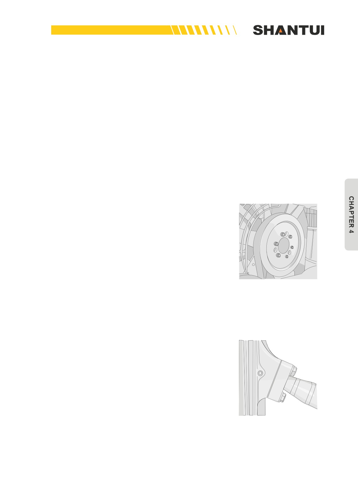
Inject grease to the grease nozzle shown in the figure.
1.
1 place: Fan pulley (Figure 4-1)
2.
2 places: Tension roller and tension roller’s bracket
Figure 4-1
3.
1 place of the support rod (Figure 4-2) 3 places of straight
tilt blade, and 2 places of angle blade
Figure 4-2
157
MAINTENANCE | MAINTENNANCE
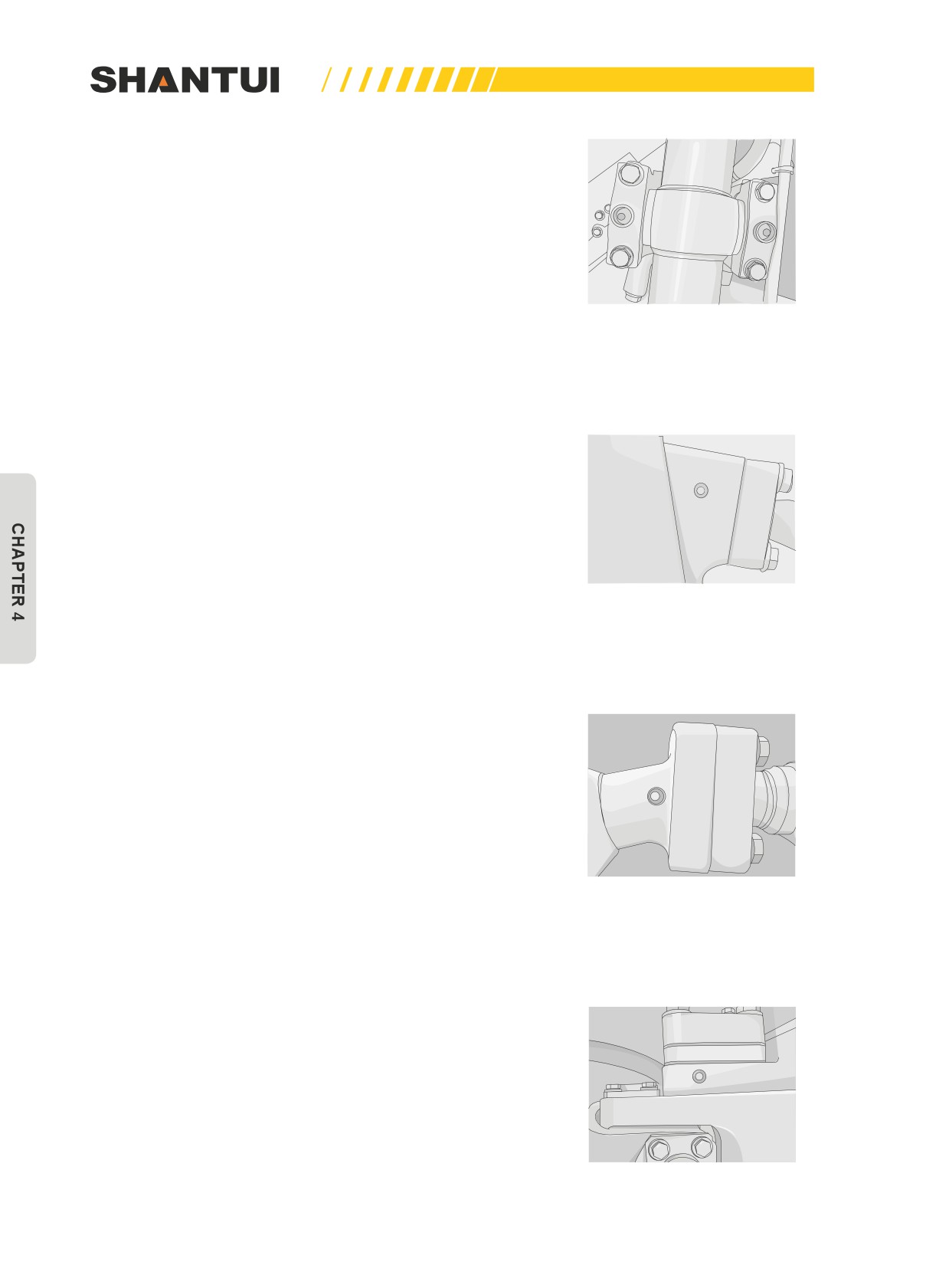
4.
4 places of oil cylinder’s bracket (Figure 4-3)
Figure 4-3
5.
1 place of the tilt cylinder’s spherical hinge (straight tilt
blade) (Figure 4-4)
Figure 4-4
6.
1 place of the support arm’s spherical hinge (straight tilt
blade) (Figure 4-5)
Figure 4-5
7. Oblique arm’s spherical hinge (Straight tilt blade) (Figure
4-6) 2 places
Figure 4-6
158
MAINTENNANCE | MAINTENANCE
8. Applying grease to the connector of the blade’s oil cylinder
Figure 4-7
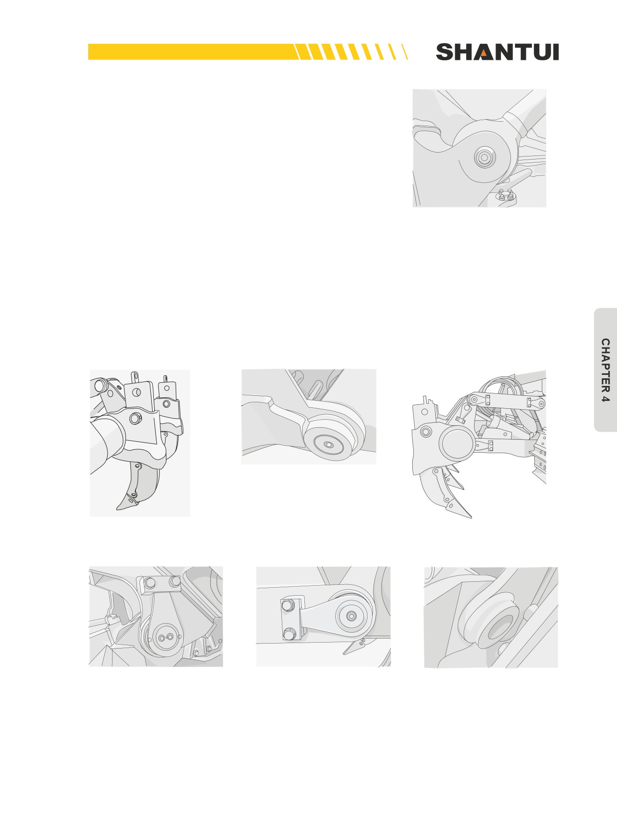
9. Ripper’s various hinges (Figure 4-8-4-13):
a. Upper connecting rod (8 places);
b. The top part of the oil cylinder’s piston rod (2 places);
c. The lower connecting frame’s pin (4 places).
d. The lower connecting frame’s shaft (4 places).
Figure 4-8
Figure 4-9
Figure 4-10
Figure 4-11
Figure 4-12
Figure 4-13
159
MAINTENANCE | MAINTENNANCE
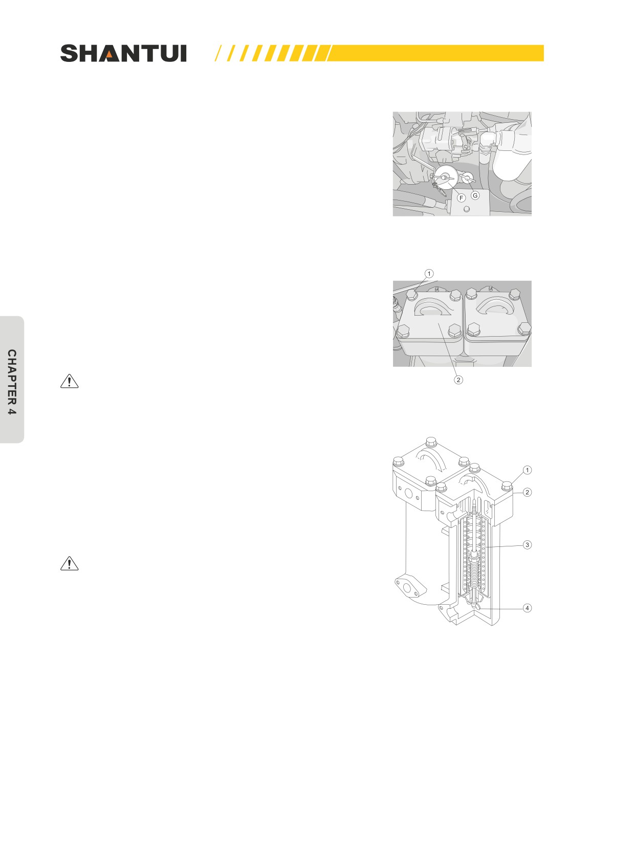
10. Engine oil pan and filter
• Remove the cover installed on the bottom of the body.
Remove the drain plug and release the drain valve. After
draining, tighten the drain valve and the drain plug.
• Use filter wrench to rotate it counterclockwise, to remove
the engine oil filter’s and bypass oil filter’s cartridges. Fill
the new engine oil filter’s and bypass oil filter’s cartridges
with engine oil, apply a small amount of the engine oil on
the gasket, and screw it on the filter’s seat. When the gas-
ket touches the sealing surface, make
3/4-1 more turns.
Figure 4-14
After replacing the filter’s cartridge, add engine oil through
the oil injection port (F) (Figure 4-14).
• And then, let the engine idle for a while, and detect the oil
level. The type of lubricant used depends on the ambient
temperature. See the “USE OF FUEL, COOLANT AND LU-
BRICANTS ACCORDING TO AMBIENT TEMPERATURE”
for reference. The oil should be changed every 6 months.
Before installing the filter’s cartridge, you must inject the
engine oil into the filter’s cartridge.
Always use Shantui genuine filters.
Figure 4-15
11. Gearshift’s oil filter and steering oil filter.
• Remove the bolt (1), pull up the cap (2), and take out the
filter element and the valve along with the cap (2). Remove
the butterfly-shaped nut of the tightening valve (4), and
take out the filter element (3) from the oil filter. Clean the
inner part of the housing and the parts removed, and install
the new filter element in the oil filter. (See Figure 4-15 and
Figure 4-16)
Always use Shantui genuine filters.
Figure 4-16
160
MAINTENNANCE | MAINTENANCE
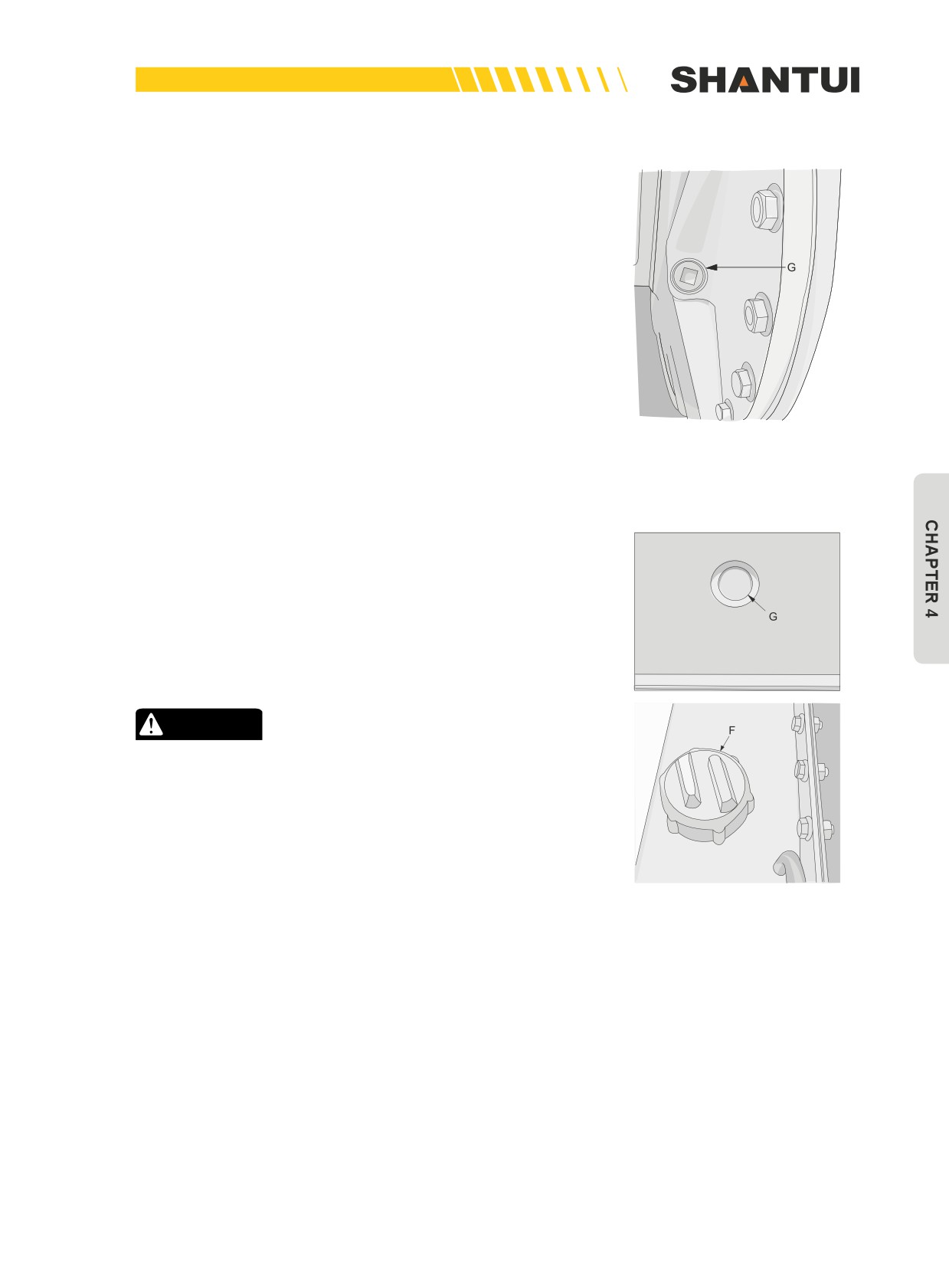
12. Final drive case
• Remove Plug (G). If it is found that the oil is not filled near
the bottom side of the plug’s hole, add lubricant via the
plug’s hole. The lubricant used depends on the ambient
temperature. See the “USE OF FUEL, COOLANT AND LU-
BRICANTS ACCORDING TO AMBIENT TEMPERATURE”
for reference. When performing maintenance, park the ve-
hicle on a level ground.
Figure 4-17
13. Hydraulic tank (See Figure 4-18)
• Put the blade and the ripper on the ground horizontally,
stop the engine, and wait for 5min to check the oil level. If
the oil level is not within the red circle in the Observation
Window (G), replenish the hydraulic oil to the oil tank via
the Oil Injection Port (F).
CAUTION
• When the oil temperature is high, do not remove the
cap. Hot oil sometimes can spurt out. When removing
the cap, slowly rotate the cap, to release the internal
pressure. The lubricant type used depends on the am-
bient temperature. See the “USE OF FUEL, COOLANT
AND LUBRICANTS ACCORDING TO AMBIENT TEM-
PERATURE” for reference.
• Before the engine is started, perform the routine check.
Figure 4-18
161
MAINTENANCE | MAINTENNANCE
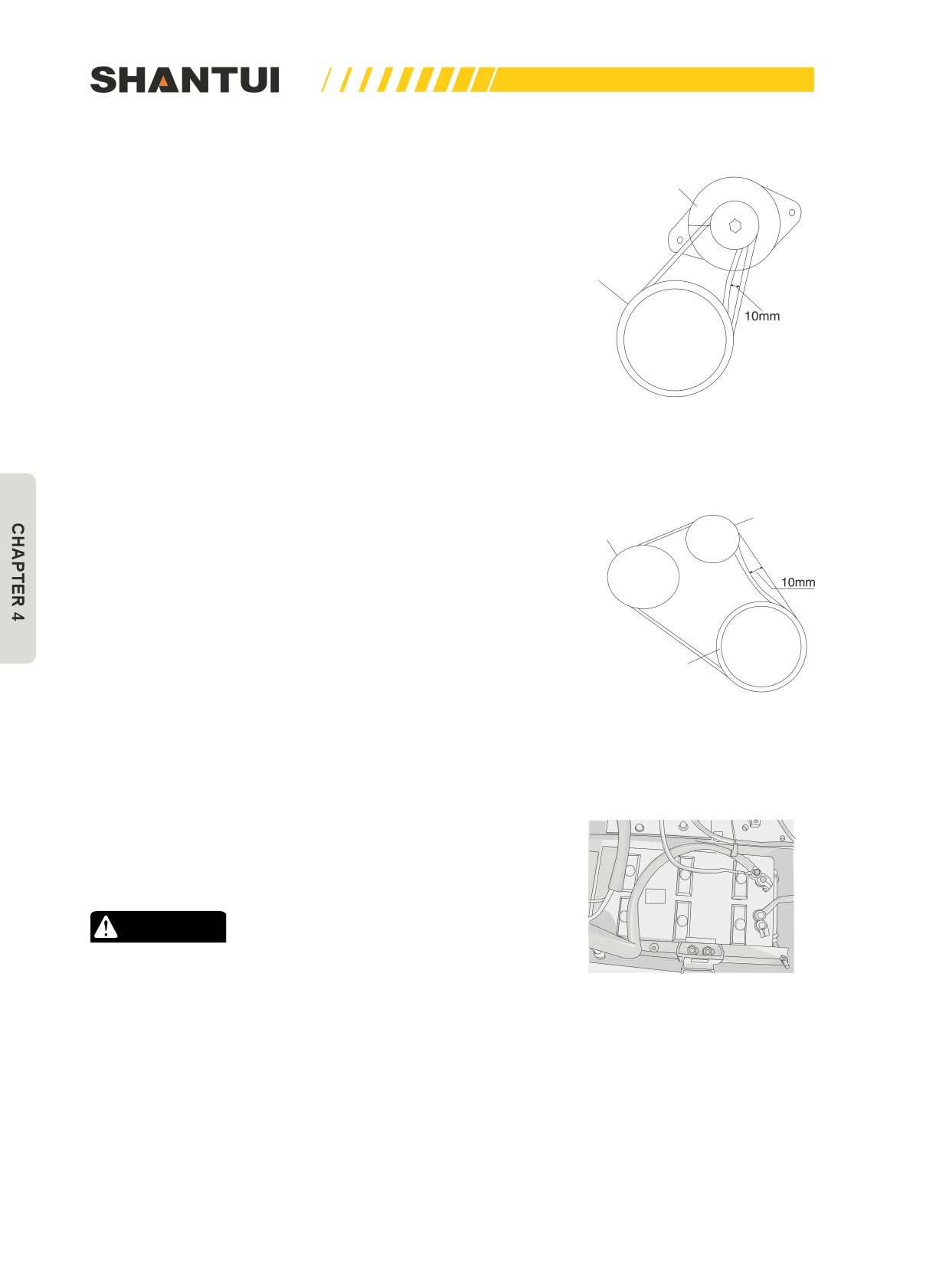
14. Generator’s driving belt
• The standard is that when you use a force of about 60N to
Generator
press the belt in the direction shown by the arrow in Figure
4-19, you can press it down by 10mm, or adjustment should
be made. You should also check the belt for damage. When
Accessory
the belt is extended and cannot be adjusted any more, or
transmission
pulley
when there are cuts and cracks, replace the belt immedi-
ately. The two belts should be replaced. After the new belts
are installed, test run them for one hour before check and
adjusting. The V-shaped belt is not allowed to contact the
V-groove’s bottom.
Figure 4-19
15. The water pump’s driving belt (Figure 4-20)
• The check and adjustment method is the same as that of
Tension roller
Water pump
the engine’s driving belt.
pulley
Accessory
transmission
16. Battery electrolyte (Figure 4-21)
pulley
• If the liquid level of the battery is lower than the required
Figure 4-20
level (10-12mm above the limit level), distilled water will
need to be added. If the electrolyte is reduced because of
overflow, inject dilute sulphuric acid of the same concentra-
tion to the battery. Clean the breather hole on the battery’s
cap when checking the liquid level.
• Don’t use the metal funnel to add liquid.
WARNING
• To avoid the gases from explosion, keep fire or sparks
away from the battery.
• If the electrolyte is spilled to skin or clothes, wash with
Figure 4-21
plenty of clean water immediately.
162
MAINTENNANCE | MAINTENANCE
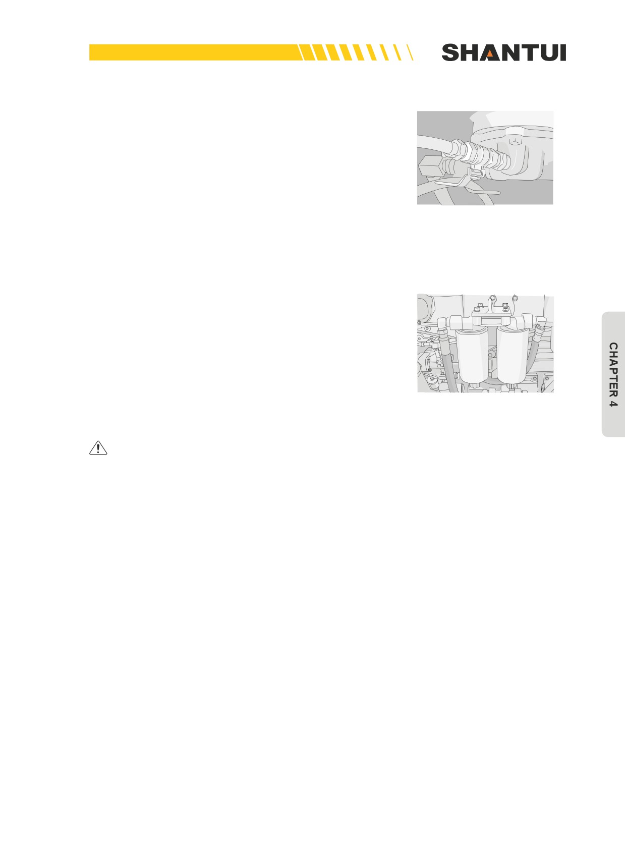
17. Exhaust impurities and water from fuel tank (Figure
4-22)
• Open the back cover, and loosen the valve on the fuel
tank’s bottom, to exhaust water and impurities.
Figure 4-22
4.1.4 EVERY 500 HOURS SERVICE
Maintenance for every 250 hours service should be car-
ried out at the same time.
1. Fuel filter
• Close the valve on the fuel tank’s bottom (See Figure 4-22),
and use the filter’s wrench to remove the fuel filter’s car-
tridge (Figure 4-23). Fill the new filter’s cartridge with clean
fuel, and apply a small amount of engine oil on the gasket.
Install the filter’s cartridge, tighten it with hand until the
Figure 4-23
gasket contacts the filter’s seat, and then tighten it 1/2-3/4
more turns (Do not tighten it too much).
Always use Shantui genuine filter’s cartridge.
2. Breather
Remove the breather, and use diesel to flush the dust accumu-
lated within it.
• Steering clutch’s case (1 place)
• Final drive’s case (2 places)
3. Fan belt
• Check the V-shaped belt, and if there are the following cir-
cumstances, replace the V-shaped belt:
• When the V-shaped belt contacts the bottom of the pulley’s
groove; when the V-shaped belt is worn, and its surface is
lower than the pulley’s outer diameter;
• when the V-shaped belt has cracks or peels off. For details
about the replacement procedure, see the “Fan belt adjust-
ment”.
163
MAINTENANCE | MAINTENNANCE
4.1.5 EVERY 1000 HOURS SERVICE
Maintenance for every 250 and 500 hours service should
be carried out at the same time. Inject grease to the grease
nozzle shown in the figure.
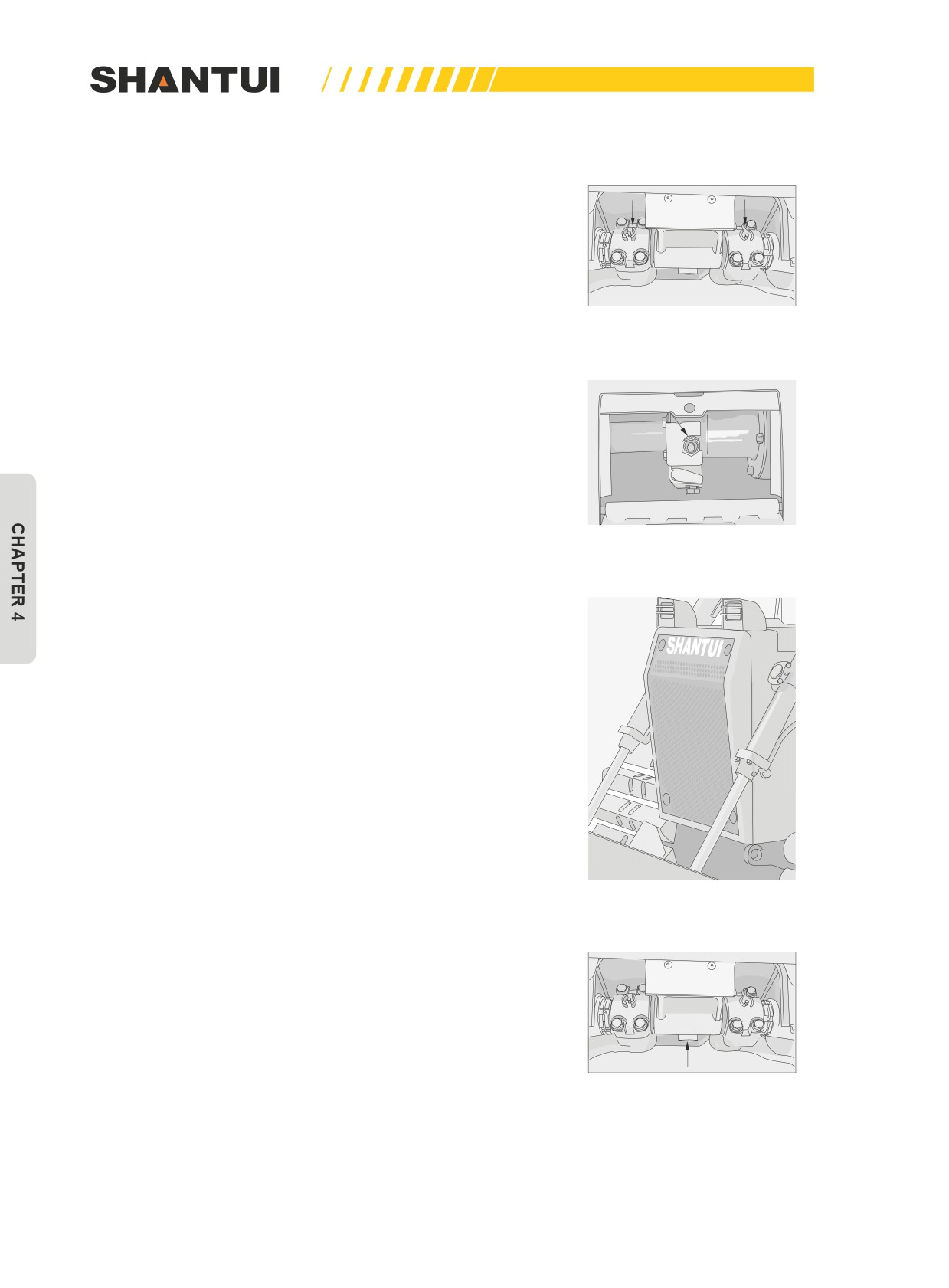
1.
Universal joint (8 places)
2.
Add lubricating grease to the half shaft’s bush (Figure 4-24)
(2 places)
3.
Oil cylinder for idler tension (Figure 4-25) (2 places)
Figure 4-24
4.
Water tank’s radiation fin (Figure 4-26)
•
Loosen the guard gate’s bolt, and open the guard gate.
Use compressed air to blow sundries such as mud, dust or
leaves off from the water tank’s radiation fin. You can also
use steam or water to replace the compressed air. Check
the water tank’s rubber tube for cracks or embrittlement,
and replace it if necessary. Check the rubber tube’s clamp
to see if it’s loose.
Figure 4-25
5.
Steering clutch case (including the bevel gear case)
and transmission case.
•
Screw off the oil drain plug on the transmission case’s
housing, and tighten it again after draining the old engine
oil.
•
Add the engine oil to the required oil level through the
transmission case’s oil port.
•
Choose an oil listed in the “USE OF FUEL, COOLANT AND
LUBRICANTS ACCORDING TO AMBIENT TEMPERA-
TURE”, and add it from the oil injection port.
•
Remove the drain plug on the bottom of the body (the ar-
row in Figure 4-27) to drain the oil, and tighten the drain
plug again after draining the oil.
Figure 4-26
Figure 4-27
164
MAINTENNANCE | MAINTENANCE
•
Remove the left floor, the bolt, the cap, the steering clutch’s
strainer and the magnet; loosen the bolt, and after cleaning
the inside of the housing, the strainer and other parts re-
moved, re-install them back to their appropriate positions.
•
If the strainer is damaged, change a new strainer.
•
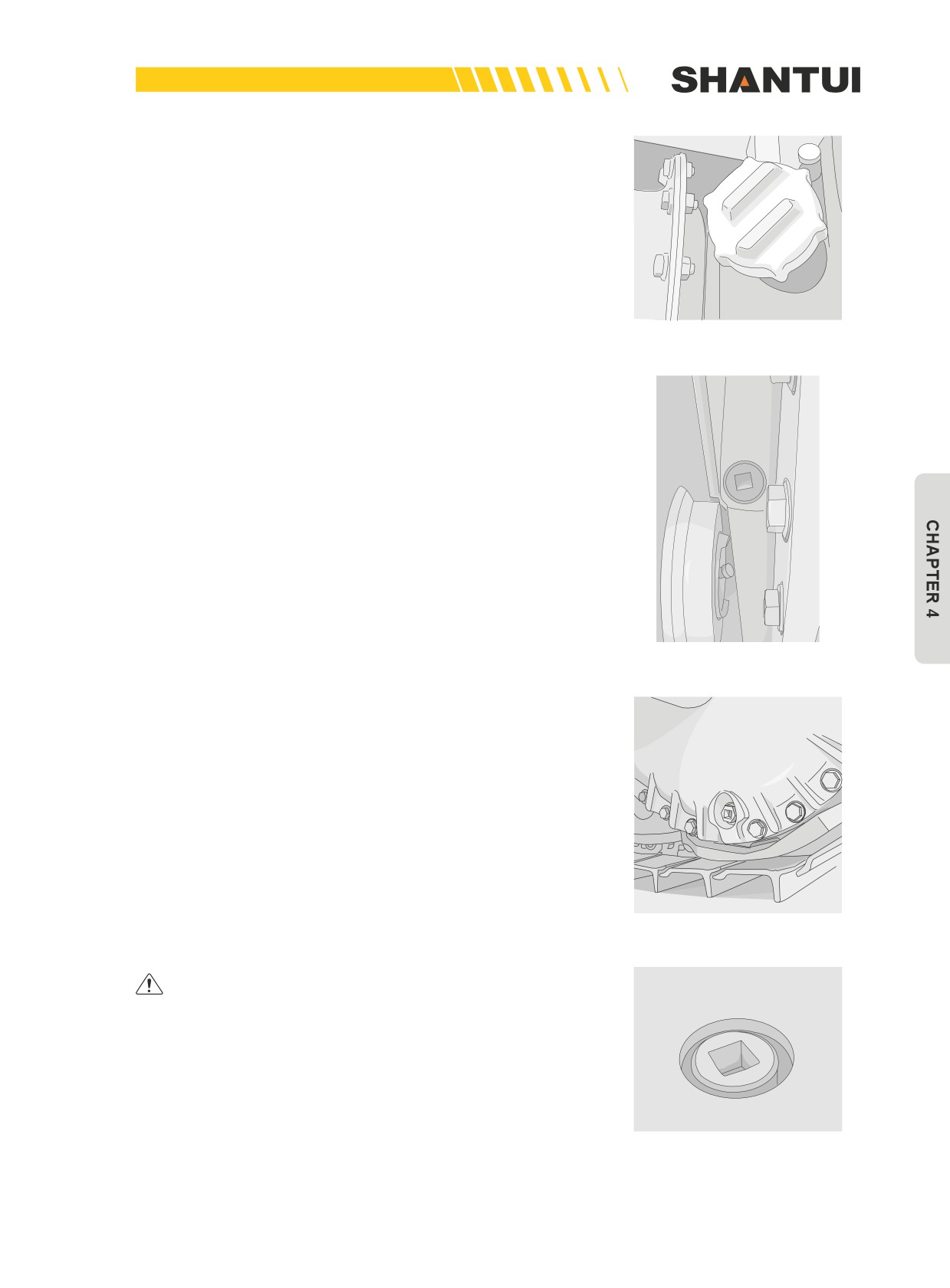
After replacing the gearshift and steering oil filter’s element
(See “EVERY 250 HOURS SERVICE”), add the required
amount of engine oil through the oil injection port. Amount
of oil added: 90L (Figure 4-28). The lubricant used depends
on the ambient temperature. See the “USE OF FUEL,
Figure 4-28
COOLANT AND LUBRICANTS ACCORDING TO AMBIENT
TEMPERATURE” for reference.
6.
Final drive case (Figure 4-29 and Figure 4-30)
•
Remove the oil filler plug from two sides of the body, and
then remove the drain plug to drain the oil. After the drain-
ing, tighten the drain plug.
•
Inject the required amount of the engine oil through the
oil filler plug (See “EVERY 250 HOURS SERVICE”). The
lubricant type used depends on the ambient temperature.
See the “USE OF FUEL, COOLANT AND LUBRICANTS
ACCORDING TO AMBIENT TEMPERATURE” for refer-
ence. Amount of oil added on each side: SD22, SD22E and
SD22D: 41L; SD22S and SD22R: 51L.
Figure 4-29
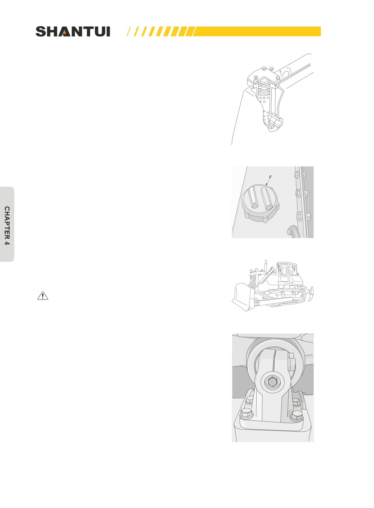
7. Hydraulic tank and filter(Figure 4-31-Figure 4-33)
• Remove the drain plug on the bottom of the oil tank, and
loosen the drain valve. After draining, tighten the valve and
drain plug. Remove the bolt, cap and filter element. Clean
the removed parts and filter’s inside, and install the new
filter element. Inject the required amount of the hydraulic
oil through the oil injection port-F (See the “EVERY 250
HOURS SERVICE”). Amount of oil added: 110L. The lubri-
cant type used depends on the ambient temperature. See
the “USE OF FUEL, COOLANT AND LUBRICANTS AC-
Figure 4-30
CORDING TO AMBIENT TEMPERATURE” for reference.
Always use Shantui genuine filters.
Figure 4-31
165
MAINTENANCE | MAINTENNANCE
8. Walking parts
• Stop the vehicle on a level ground, and check the oil con-
sumption in the track roller, carrier roller, and idler one by
one. (Figure 4-34)
• Slowly screw loose the seal bolt (Figure 4-35) to see if
there is oil seeping out from the threads. If yes, it means
that there is enough oil, and you should tighten the bolt im-
mediately. If there is still no oil flowing out after the seal bolt
is completely removed, it means that there isn’t enough oil.
In this case, you should require your local Shantui distribu-
tor to make necessary repair.
Figure 4-32
9. The roller of the tubocharger has clearance
• Contact your local Shantui distributor for necessary check
or repair.
10. Corrosion resistor (water filter)
• Shut down the corrosion resistor’s water inlet/outlet valve.
Use the filter’s wrench to turn the corrosion resistor’s fil-
Figure 4-33
ter cartridge counterclockwise to remove it. Apply a small
amount of oil on the sealing surface and install a new ele-
ment. During installation, tighten 1/2-3/4 turns after the
sealing surface is in contact with the cap. (Don’t turn it too
tight.) After the replacement, open the valves.
Always use Shantui genuine filters.
Figure 4-34
Figure 4-35
166
MAINTENNANCE | MAINTENANCE
4.1.6 EVERY 2000 HOURS SERVICE
Maintenance for every 250, 500, and 1000 hours service
should be carried out at the same time.
Lubricating, Inject grease to the grease nozzle shown in
the figure.
1. Equalizer bar’s shaft (1 place)
2. Brake pedal’s axle (Figure 4-36) (5 places)
Figure 4-36
3. Tubocharger
• The excessive carbon black or grease adhered to the tu-
bocharger pump impeller may influence the normal perfor-
mance of the tubocharger, and sometimes may damage the
tubocharger. Contact your local Shantui distributor for nec-
essary check or cleaning. Do not use steel brush or similar
things to do that, to avoid the pump impeller’s surface from
being damaged.
4. Valve clearance
• Contact your local Shantui distributor to check the valve
clearance, because this requires special tools.
4.1.7 EVERY 4000 HOURS SERVICE
Maintenance for every 250, 500, 1000, and 2000 hours ser-
vice should be carried out at the same time.
1. Water pump
• Check pulley to see if it’s loose or if there is leakage of
grease or water. If yes, contact your local Shantui distribu-
tor to repair or replace the water pump.
2. Fan pulley and tension wheel
• Check the wheels to see if they are loose or if there is leak-
age of grease. If yes, contact your local Shantui distributor
to repair or replace the wheel assembly.
167
MAINTENANCE | MAINTENNANCE
4.1.8 MAINTENCE WHEN NEEDED
The following items should be checked and serviced when
required depending on the result of visual inspection.
Air cleaner
1.
Inspection:
•
If the monitor lamp of the monitor’s air filter blinks, you
should clean the air cleaner’s element. Stop the engine
when doing the cleaning.
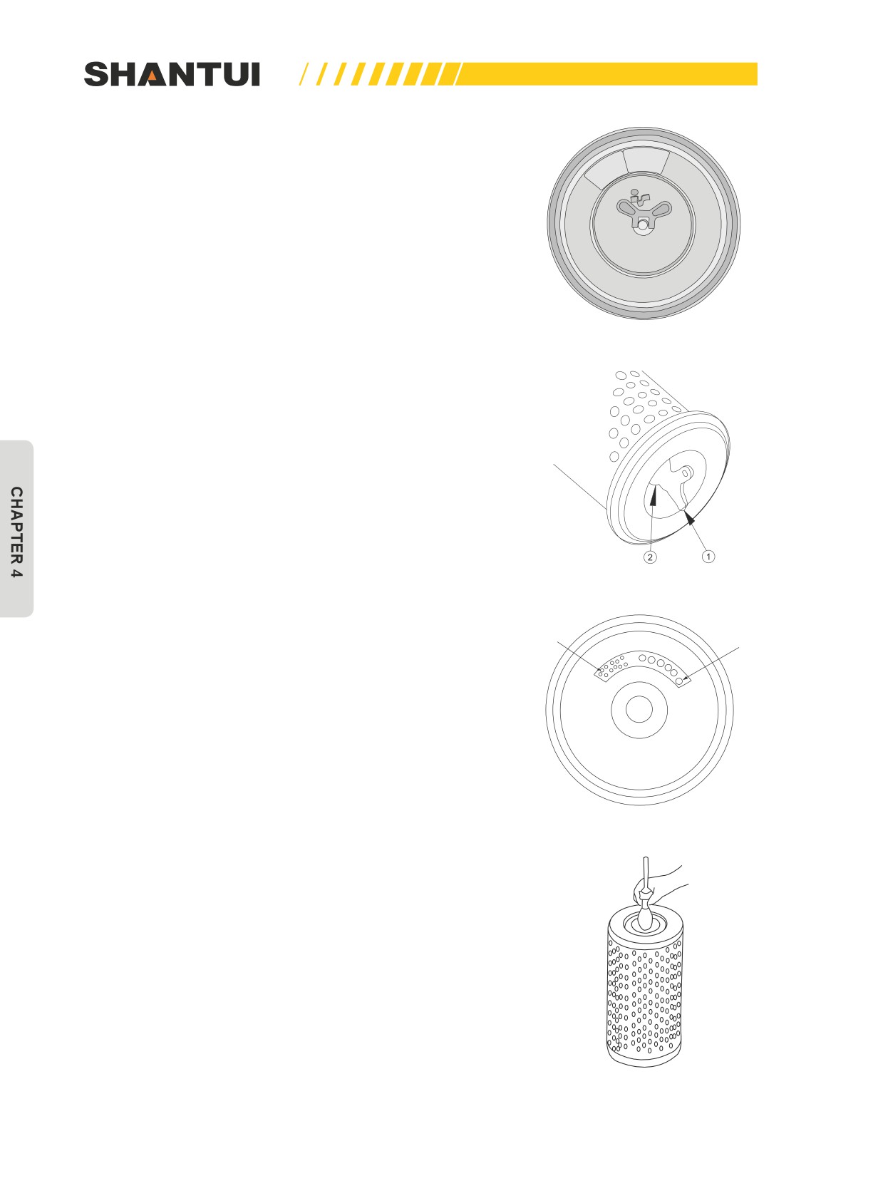
Figure 4-37
2.
Clean or replace the outer filter element:
•
Remove the butterfly-shaped nut (1) and the outer filter
element (Figures 4-37 and 4-38), and clean the inside of
the air cleaner’s housing. Clean and check the outer filter
element (For the cleaning method, See the “Outer filter
element cleaning method”). For every time the outer filter
element is cleaned, tear off one letter sticker on the inner
element’s label plate (Figure 4-39), and install the cleaned
outer filter element.
•
When the sealing gasket (2) or the butterfly-shaped nut (1)
is damaged, they should be replaced. (Figure 4-38)
•
Check the inner filter element’s mounting nut to see if it’s
Figure 4-38
loose. If yes, tighten it.
Letter
Lable plate
sticker
3.
Replace the inner filter element (when the outer filter
element has been cleaned for 6 times or when the in-
ner filter element is damaged)
•
Remove the outer filter element first, and then remove the
inner filter element. Cover the air intake. Clean the inside of
the air cleaner’s housing, and remove the air intake’s cap.
•
Install the new inner filter element to the connector, and
then tighten it with nut. Install the outer filter element.
Figure 4-39
Figure 4-40
168
MAINTENNANCE | MAINTENANCE
CAUTION
•
An outer filter element that has been cleaned for 6 times and has been used for 1 year
should be replaced, and the inner filter element should also be replaced at the same time.
•
Do not clean or replace the air cleaner’s element when the engine is running.
•
Do not attempt to clean the inner filter element and use it again.
4. Outer filter element cleaning method
a .Cleaning using the compressed air
• Use dry compressed air (less than 0.7Mpa) to blow the inside of the filter element directly along
the pleat. Continue to directly blow it along the outer pleat, and then repeatedly blow the inner
side. Finally check if the filter element is already clean.
b. Washing with water
• Use tap water (less than 0.3Mpa) to flush along the inner pleat of the filter element, and then
flush along the outer pleat. Repeat this, and check after it is dry.
c. Using a cleaning agent
• In order to remove the grease and carbon black on the filter element, you can dip it in the luke-
warm water containing a neutral cleaning agent to clean it, and then use clean water to rinse it.
Check after it is dry.
• Using dry compressed air (less than 0.7Mpa) to repeatedly blow it inside out can dry it more
quickly.
• Do not heat it to dry it.
• Using lukewarm water (about 40°C) to replace soap water is also very effective.
• After cleaning and drying it, when checking it by dropping a lamp into the outer filter element, if
you find that there are small holes or there are already some very thin parts, replace the outer fil-
ter element. (Figure 4-40)
• If the outer filter element can still be used, after dusting, keep it in a dry location.
• When cleaning the outer filter element, do not use other objects to knock or impact it.
• An outer filter element with an unevenly or deformed pleat or a damaged gasket cannot continue
to be used.
CAUTION
•
When using the compressed air, wear the safety glasses and other objects that can en-
sure safety.
169
MAINTENANCE | MAINTENNANCE
Clean the inside of the cooling system
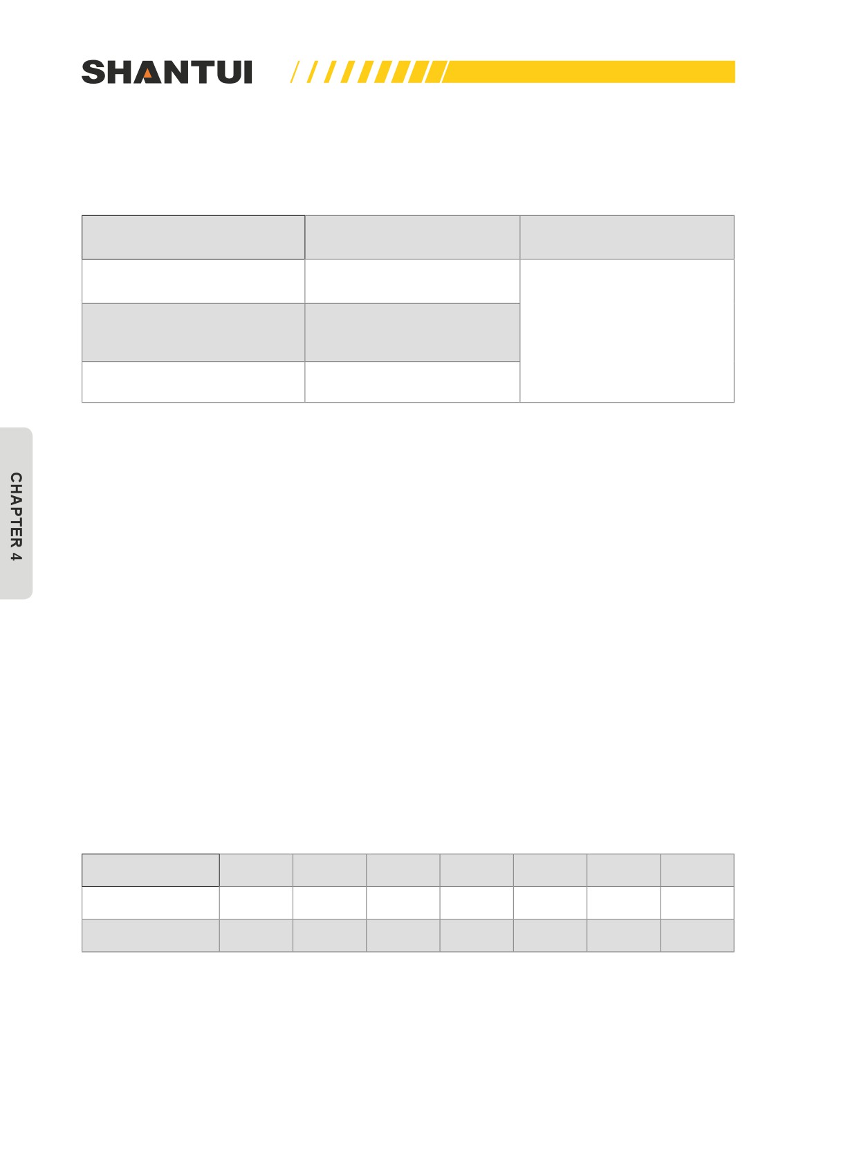
1. Replace coolant, corrosion resistor and clean the inside of the cooling system according
to the table below.
Cleaning inside of cooling
Kind of coolant
system and changing
Replacing corrosion resistor
coolant
Every year (autumn) or every
Permanent type antifreeze (All
2000 hours, whichever comes
season type)
first
Every 6 months (spring, au-
Every 1000 hours and when
Non permanent type antifreeze
tumn) (Drain antifreeze in
cleaning the inside of the cool-
containing ethylene glycol (win-
spring, add antifreeze in au-
ing system or when changing
ter, one season type)
tumn)
coolant
Every 6 months or every 1000
Not using antifreeze
hours, whichever comes first
• Stop the machine on level ground when cleaning or changing the coolant.
• Use a permanent type of antifreeze. If, for some reason, it is impossible to use permanent type
antifreeze, use an antifreeze containing ethylene glycol.
• The corrosion resistor (water filter) must be replaced.
• The cooling water has to be the tap water used in cities. When diluting the coolant, use distilled
water or tap water (soft water). Natural water, such as river water or underground water (hard
water), contains a large amount of minerals (calcium, magnesium etc), and is easy to form water
scale inside the engine or the radiator. Once scale accumulates in the engine or the radiator, it’s
very hard to be removed. We recommend you to use water less than 100PPM.
• The ratio of antifreeze to water depends on the ambient temperature. When deciding the ratio
of antifreeze to water, check the lowest temperature in the past, and decide from the mixing rate
table given below.
• It is actually better to estimate a temperature about 10°C lower when deciding the mixing rate.
• The ratio of antifreeze to water during the transportation of the machine should be determined
according to a temperature about 20°C lower than the expected lowest temperature during the
transportation. (If you cannot make an estimate, please mix them at the biggest ratio, or if the
conditions cannot be met, drain all the coolant, and re-add it as required before operation).
The blending ratios of water and antifreeze are shown in the table below:
Min. atmospheric
Above
-15
-20
-25
-30
-35
-40
temperature °C
-10
Amount of
30
36
41
46
50
54
58
antifreeze %
Amount of water
70
64
59
54
50
46
42
%
170
MAINTENNANCE | MAINTENANCE
2.
Clean the cooling system
•
Turn off the engine, and shut down the corrosion resistor’s
water inlet/outlet valve.
•
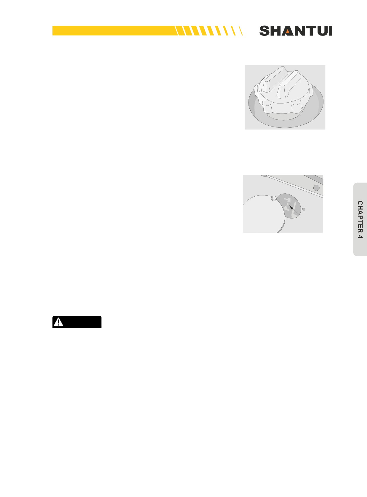
Slowly rotate the radiator’s cap until it is open. (Figure 4-41)
•
When removing the radiator’s cap, you must slowly rotate
the cap, to release the pressure.
•
Loose the water drain valve on the bottom of the water tank
and the water drain valve on the two ends of the oil cooler,
to drain the cooling water. (Figure 4-42)
•
Close the water tank’s water drain valve and the water
Figure 4-41
drain valve on the two ends of the oil cooler, and add clean
water (tap water used in cities), until the water is added to
the water intake’s edge. When the water reaches the water
intake’s edge, let the engine idle, open the water tank’s wa-
ter drain valve and the water drain valve on the two ends of
the oil cooler, and continue to add clean water to the water
tank, until the clean water continuously flows out from the
water drain valve for 10min.
•
When draining the water, adjust water flow, to ensure that
the water added is equivalent to the water drained, and to
keep the water tank full of water all the time. When the wa-
ter becomes completely clean, stop the engine. Open the
Figure 4-42
water drain valve and the water drain valve on the two ends
of the oil cooler to drain the water, and then close the water
drain valve and the water drain valve on the two ends of the
oil cooler.
•
Use the cleaning agent bought in the market to clean the
cooling system. Follow the instructions of the cleaning
agent.
CAUTION
• Antifreeze is flammable, so keep it away from flame.
• If the water temperature is high, don’t remove the cap,
as hot water may spurt out.
171
MAINTENANCE | MAINTENNANCE
3. Add the coolant
• After cleaning the cooling system, drain all the water, and
then close the water drain valve, and slowly add the cool-
ant (the coolant mixed according to the region where the
machine is used), until coolant overflows from the water
intake.
• Let the engine idle for 5min, and then run at an intermedi-
ate speed for 5min, to exhaust the air accumulated in the
cooling system. (During operation, open the radiator’s cap).
After the engine has stopped running, wait for 3min, add
coolant, until it reaches the required level, and then tighten
the cap.
Track tension
1. Inspection
• Stop the machine on level ground (stop with the transmis-
sion in FORWARD without applying the brake). Then place
a straight bar on the track shoes between the carrier roller
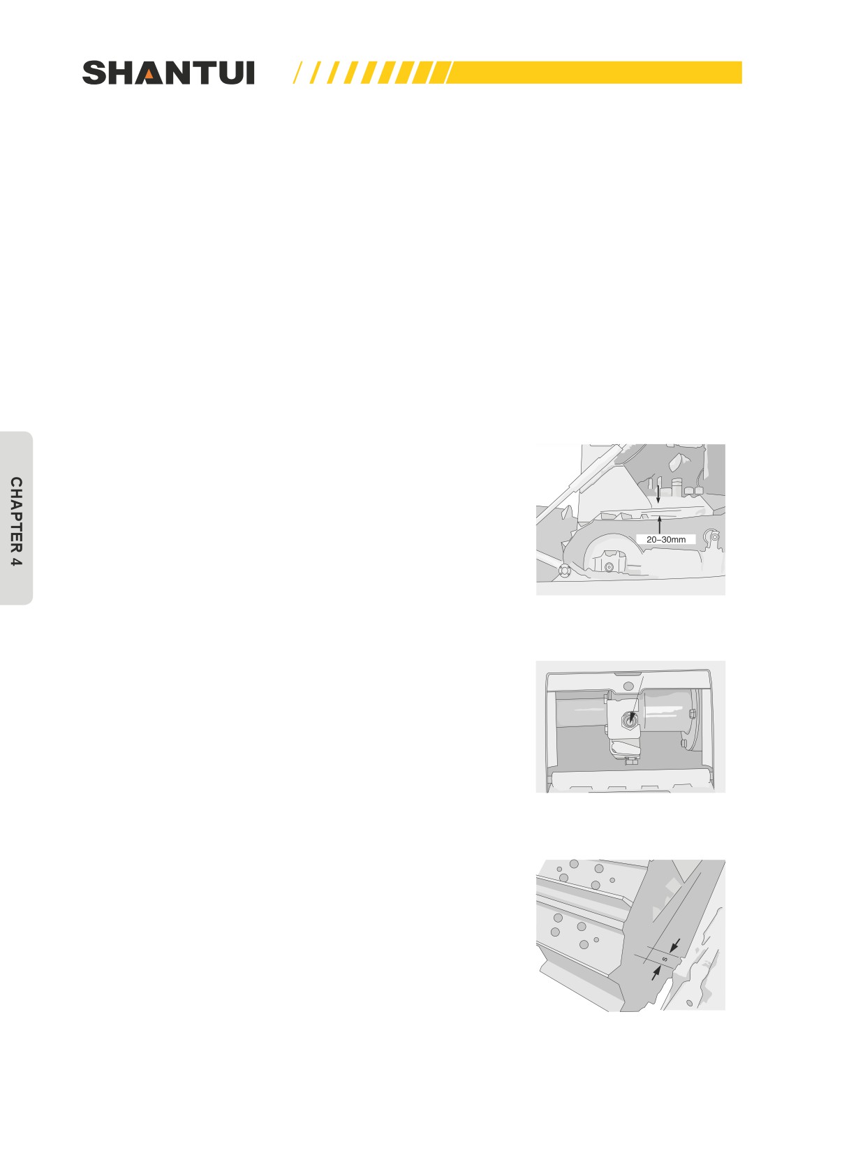
and the idler (Figure 4-43), and measure the clearance be-
tween the bar and the grouser at the midpoint. If the clear-
ance is 20 to 30mm, the tension is standard.
2. Adjustment
• In order to increase tension, pump in grease through the
grease fitting with a grease pump (Figure 4-44). On the oth-
Figure 4-43
er hand, in order to loosen tension, slowly rotate the plug
in the opposite direction for one turn, to squeeze out the
grease. If pump in the grease until S is 0mm (Figure 4-45),
and the tension is still loose, this shows that the bushing is
seriously worn and thinned. Contact your local Shantui dis-
tributor to repair or replace the track.
• If the plug or other parts are made too loose, due to the
high pressure from pumping in the grease, the parts are
easy to fly out. If the grease cannot be pumped in smoothly,
move the vehicle forward and backward for a distance.
Figure 4-44
Figure 4-45
172
MAINTENNANCE | MAINTENANCE
CAUTION
• When loosening the plug, do not do it by more than an
entire turn. Also, do not loosen any other parts except
for the plug.
Check and tighten track shoe bolts
• If the machine is used with track shoe bolts being loose,
they will break, so tighten any loose bolts immediately. First
tighten to a tightening torque of 400±40N•m, then check
that the nut and shoe are in close contact with the link con-
tact surface.
• After checking, tighten a further 120° ± 10°.
Turn or Replace the end bit and the cutting edge (Figure
4-46)
• Before the end bit and the cutting edge is worn to the edge
of the blade, turn the cutting edge over and replace the end
bit. If both sides of the cutting edge are worn, replace the
cutting edge. Raise the blade to a suitable height, put the
block beneath the push rod, to prevent the blade from fall-
ing down. Remove the end bit and the cutting edge, and
Figure 4-46
clean the mounting face. Replace the new end bit, turn over
the cutting edge (or change a new one), and tighten with
nuts. Tightening torque: 627±78N•m (64±8kgm). After oper-
ating for a few hours, tighten the nuts.
173
MAINTENANCE | MAINTENNANCE
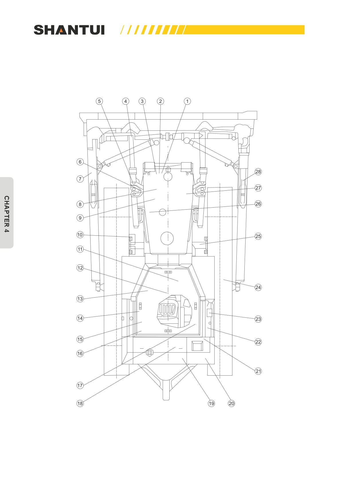
4.1.9 LUBRICATION DIAGRAM AND LUBRICATION TABLE
THE SD22 BULLDOZER’S LUBRICATION DIAGRAM:
174
MAINTENNANCE | MAINTENANCE
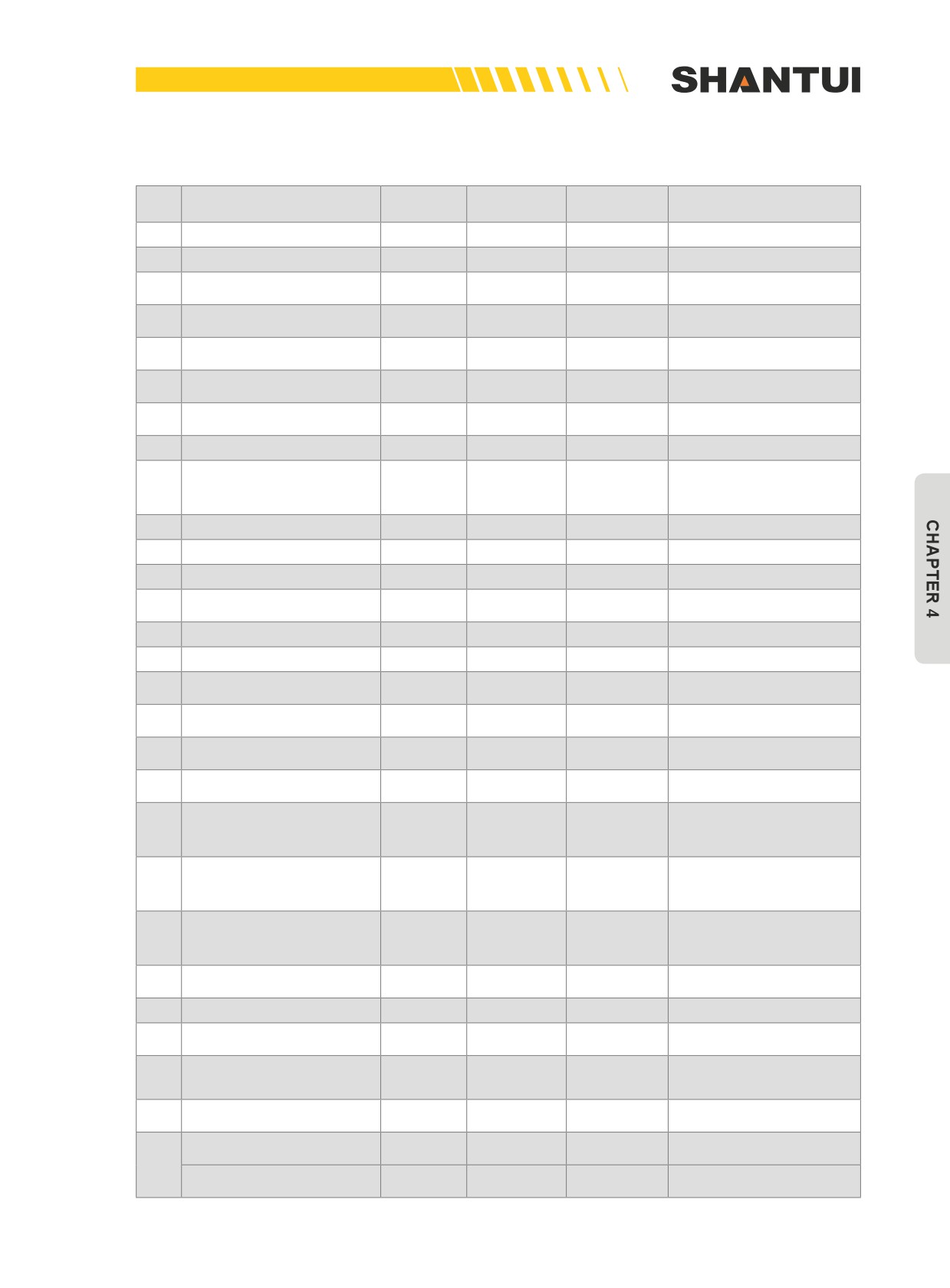
LUBRICATION TABLE (THE SD22 SERIES BULLDOZERS)
Number
Lubricating
Lubrication cycles
No.
Parts to be lubricated
Lubricants
of points
tools
(hours)
1
Fan pulley
1
Grease
Grease gun
250
2
Tension roller
1
Grease
Grease gun
250
Tension roller’s bearing
3
1
Grease
Grease gun
500
support
Oil cylinder’s spherical
4
2
Grease
Grease gun
250
hinge
Oil cylinder’s supporting
5
4
Grease
Grease gun
250
shaft
Support arm’s spherical
6
2
Grease
Grease gun
250
hinge
Lubrication support arm’s
7
2
Grease
Grease gun
250
screw bar
8
Oil cylinder’s support
2
Grease
Grease gun
250
Adding oil every 10
9
Engine oil pan
1
Oil
Oil pot
hours, and changing oil
every 250 hours
10
Steering oil filter element
2
250
11
Brake pedal
6
Grease
Grease gun
2000
12
Universal joint
8
Grease
Grease gun
1000
Washing it once every
13
Washing the strainer
1
500 hours
14
Fuel control lever’s shaft
3
Grease
Grease gun
2000
15
Brake lock lever
1
Grease
Grease gun
2000
Transmission case con-
16
3
Grease
Grease gun
2000
trol lever
Blade control lever’s
17
3
Grease
Grease gun
2000
shaft
Oblique support arm for
18
2
Grease
Grease gun
1000
lubrication
Washing it once every
19
Washing the fuel strainer
1
250 hours
Checking it every 250
20
Final drive’s gearbox
2
Oil
Oil pot
hours, and changing it
every 1000 hours
Adding oil every 10
21
Steering case
1
Oil
Oil pot
hours, and changing oil
every 1000 hours
Checking it every 250
22
Hydraulic tank
1
Oil
Oil pot
hours, and changing it
every 1000 hours
Hydraulic tank’s oil filter
Replacing it every 1000
23
1
element
hours
24
Idler’s adjusting rod
2
Grease
Grease gun
250
Equalizer bar’s main
25
1
Grease
Grease gun
250
shaft
Replacing it every 250
26
Fuel filter element
1
hours
Replacing it every 250
27
Engine oil filter
1
hours
Oblique oil cylinder’s
2
Grease
Grease gun
250
spherical hinge
28
Various hinged joints of
18
Grease
Grease gun
250 hours
the ripper (optional)
175
MAINTENANCE | MAINTENNANCE
4.1.10 ADJUSTMENT OF VARIOUS PARTS
Adjusting the brake pedal
1. Inspection
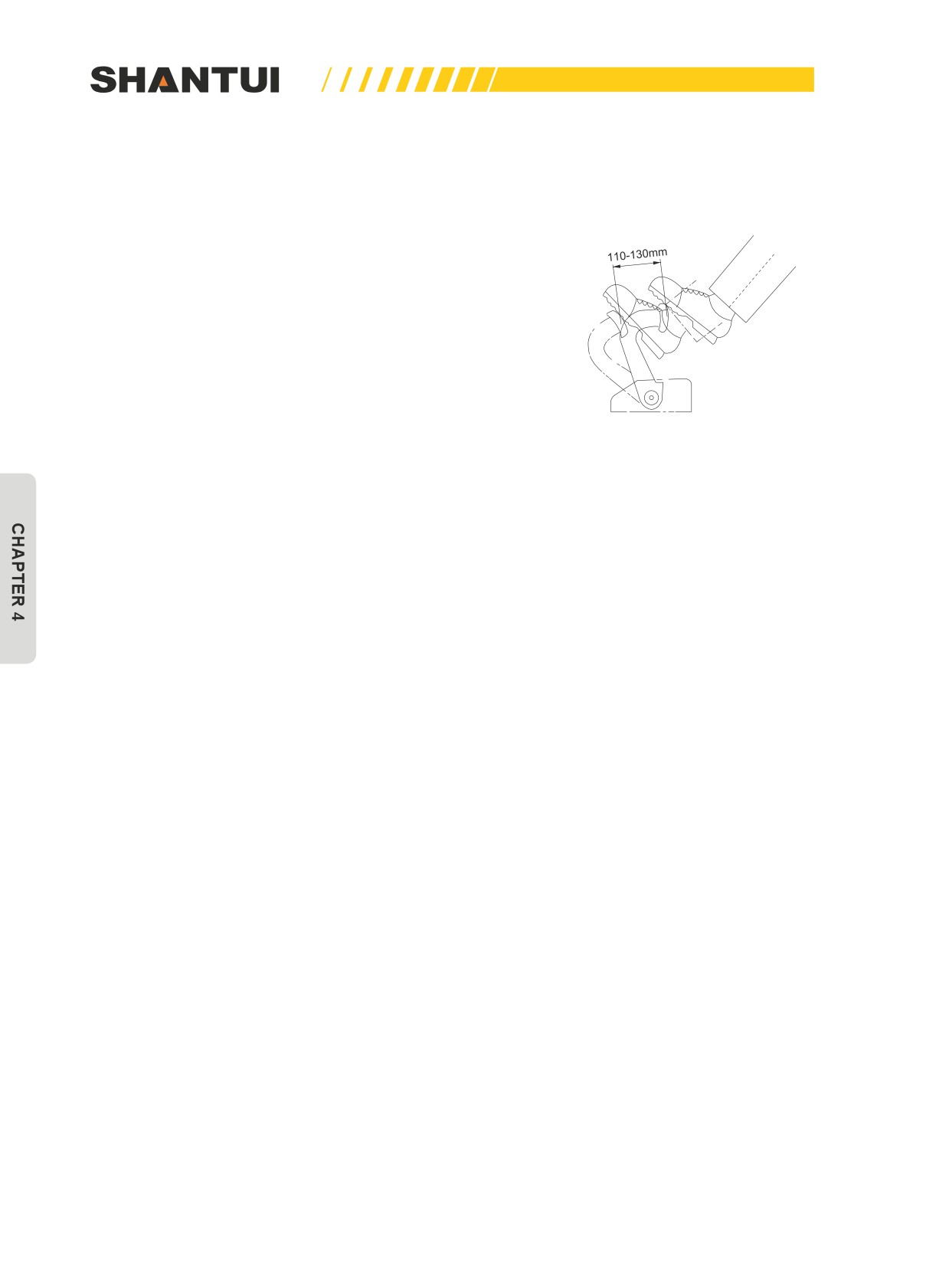
• When the brake lining is worn, the stroke of the steering
pedal will increase to make steering difficult. When the
stroke is over 190mm (when the braking force is reduced),
make adjustment as follows: standard stroke: 110-130mm
(when the engine is idling and the operation force is 150N)
Figure 4-47); 75mm (the stroke when the engine is not run-
ning).
2. Adjustment
• Remove the rear cover and the inspection cover. Tighten
the adjusting bolt until the tightening torque is 50N.m, to
Figure 4-47
make the lining and the braking drum in close contact (step
down the braking pedal to confirm the contact condition).
And then, rotate the adjusting bolt for 7/6 turns in the oppo-
site direction. The stroke of the two brake pedals should be
made the same, or the brake flexibility of the two sides will
not be the same. If A, the size of the adjusting bolt, is less
than 71mm, please contact your local Shantui dealer to get
the new brake lining.
Idler
If the idler is forced to rotate for a long time, the guide plates
on the side, on the top and on the bottom as well as the di-
recting plate will gradually become worn, causing the idler to
swing left and right, or the track’s links will get out of the idler
because the idler becomes tilted, or the idler and the links will
become unevenly worn. Therefore, you must adjust the idler
whenever it’s necessary according to the following procedure,
to enable it to be in a good operational state.
1. Adjusting the guide plates on the side(Figures 4-48~49)
• Drive the machine for 1-2m on a level ground, to tighten the
track evenly, and then stop the vehicle. Check the clear-
ance “A” between the side guide plate and the track frame
(the guide plate on each side has 4 clearances: left, right,
top, and bottom).
• If any of the clearances is over 4mm, loosen bolt (1), re-
move certain number of shims (2), and then adjust the
clearances to the standard values: 0.5~1.0mm. The shim’s
thickness is 0.5~1.0mm.
• When loosening the bolt (1), be sure not to rotate the bolt
for more than 3 turns.
176
MAINTENNANCE | MAINTENANCE
2.
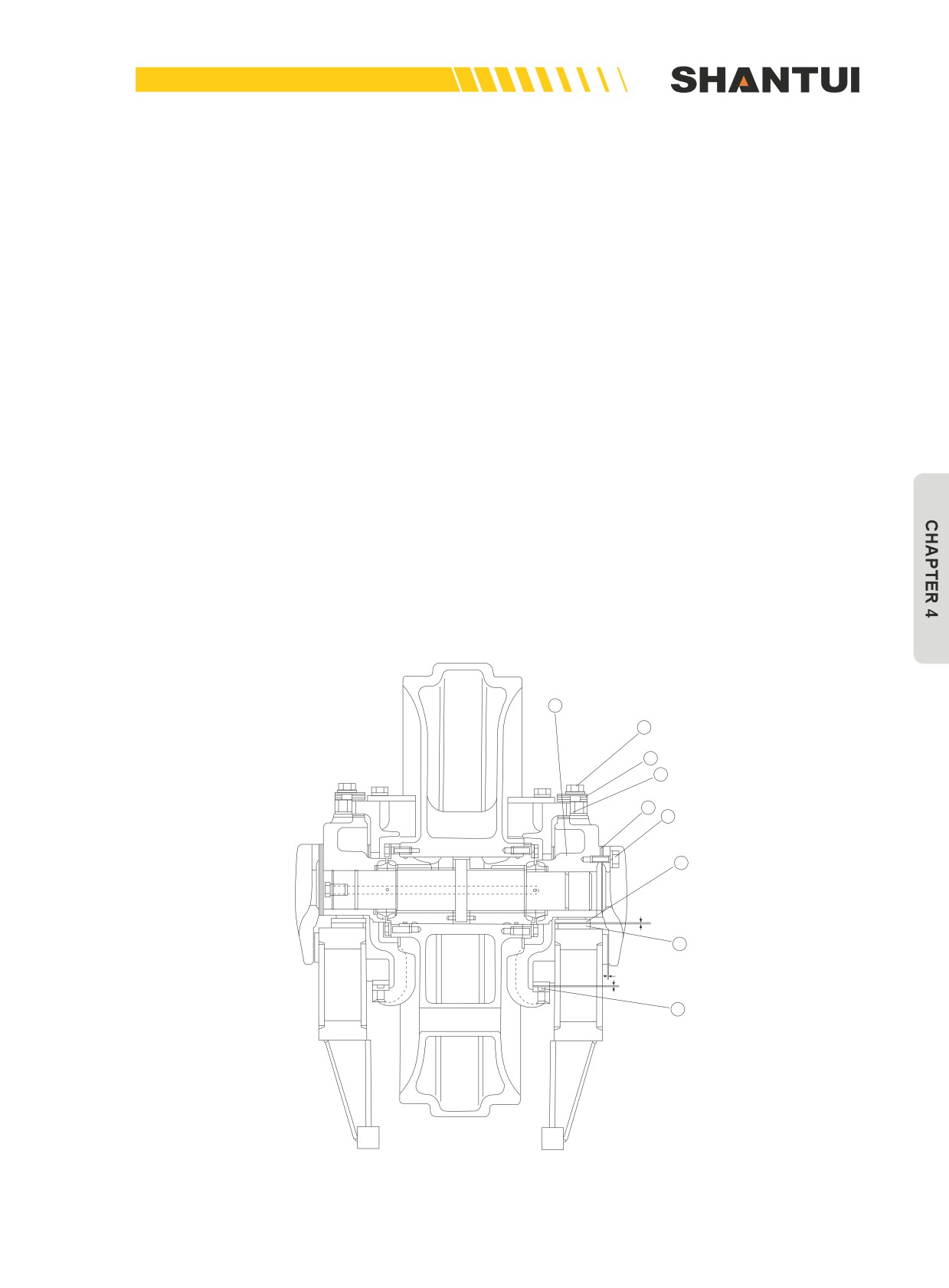
Adjusting the directing plates (4) and the top & bottom guide plates (6) (Figures 4-50~4-51)
•
Measure the clearance “B” between the track frame’s upper wearing plate (3) and the directing
plate (4) as well as the clearance “C” between the top & bottom guide plates (6) and the track
frame’s lower wearing plate. If the sum of the two clearances “B” and “C” is over 5mm, reduce it
to 2mm. The method is to pull out shim (7), to reduce it to the required thickness, and add a shim
of the same thickness to shim (8). Such adjustment can be completed using the following proce-
dure.
•
It is normal if clearance “C” is 0mm. Measure clearance “B” and minus 2mm from the value of “B”
to get the shim’s thickness (for example, if B=5mm, then the adjusting shim’s thickness should be
5-2=3mm). Shims (7) and (8) can be shims that can be pulled out.
•
Loosen bolt (9) (there are a total of 4 bolts inside and outside) until you can’t feel the force of the
spring.
•
Loosen bolt (1). Be sure not to rotate the bolt for more than 3 turns.
•
Use a stick to adjust guide frame (5) upward, to make clearance “C” 0mm. Remove shim (7) ac-
cording to the required shim’s thickness determined in the first step. Add shim (7) to shim (8)
(you need to complete this process for 8 places: the inside and outside of the left and right guide
plates as well as the front and back of each side. Before and after the adjustment, the total thick-
ness of shim (7) and shim (8) combined remains the same. If the total thickness of the two shims
is increased or decreased due to carelessness, the preload of the spring installed within the
guiding device will become inappropriate. Shim (7) and shim (8) are consisted of several pieces
of two types of shims: the 1mm shim and the 2mm shim. Tighten the spring seat’s bolt (9). The
tightening torque of bolt (1) is 500~620Nm. The maximum adjustment allowed for the top & bot-
tom guide plate is 6mm.
5
9
7
8
2
1
4
B
3
A
C
6
Figure 4-48
177
MAINTENANCE | MAINTENNANCE
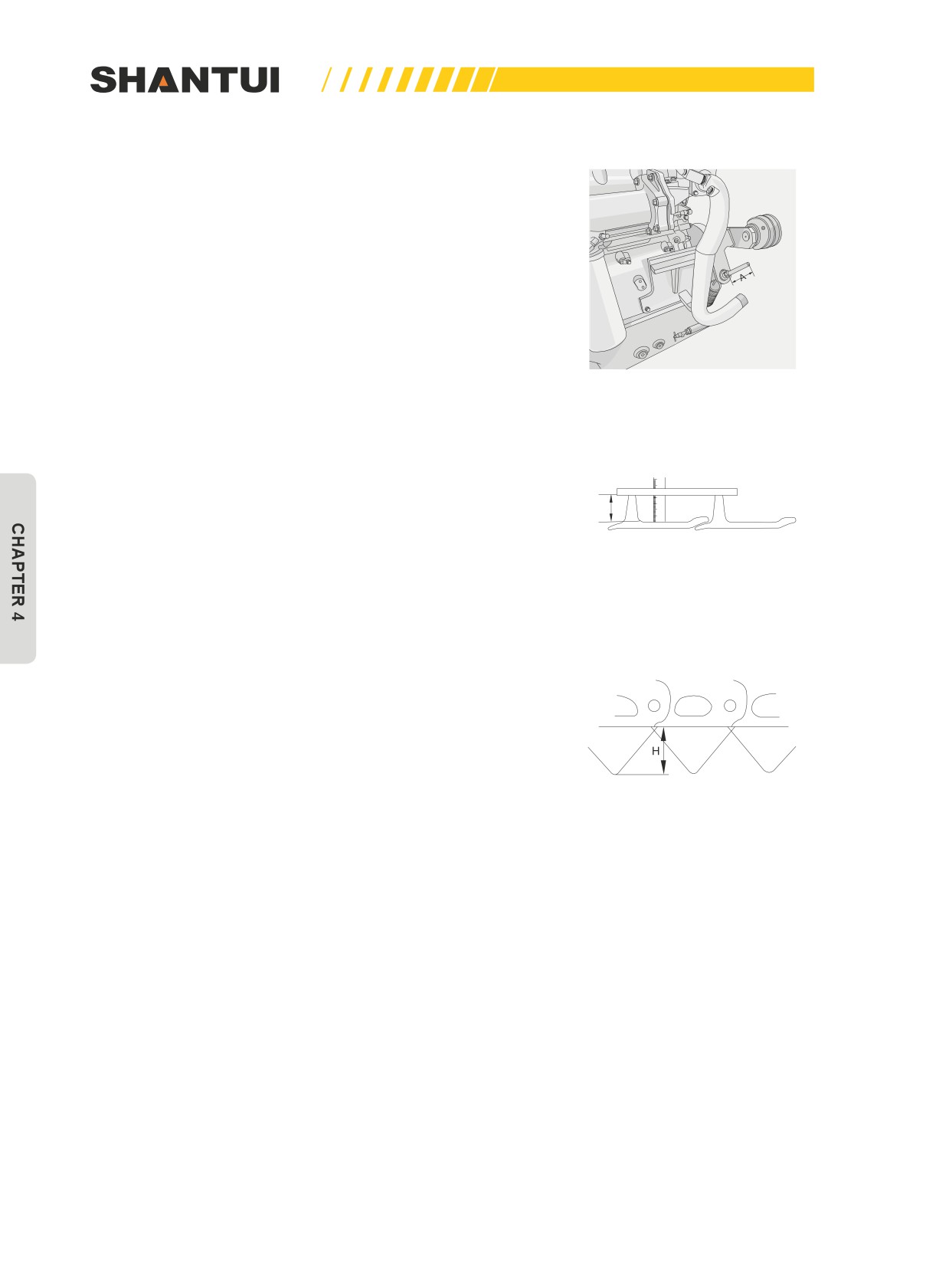
Fan belt
Because fan belt has an automatic tension device, its tension
always remains constant and has nothing to do with the V-belt.
The belt does not need to be adjusted until it is damaged. But
when replacing the old belt with a new one, you should check
if size “A” is 113±5mm (Figure 4-49), and when its value is not
within this range, it should be adjusted.
When changing the V-belt, you should change both belts at the
same time.
Figure 4-49
Walking parts
The check and adjustment of track tension: For rocky areas,
the track should be slightly tighter. For areas with clay and
H
sandy soil, the track should be a little bit loose (See “Mainte-
nance when needed” for check and adjustment methods).
Figure 4-50
1. Measuring height of grouser
• Take a tight track shoe and measure the height of grouser.
(Figures 4-50 and 4-51)
Standard height (H): 72mm
Repair limits (H):25mm
Figure 4-51
178
MAINTENNANCE | MAINTENANCE
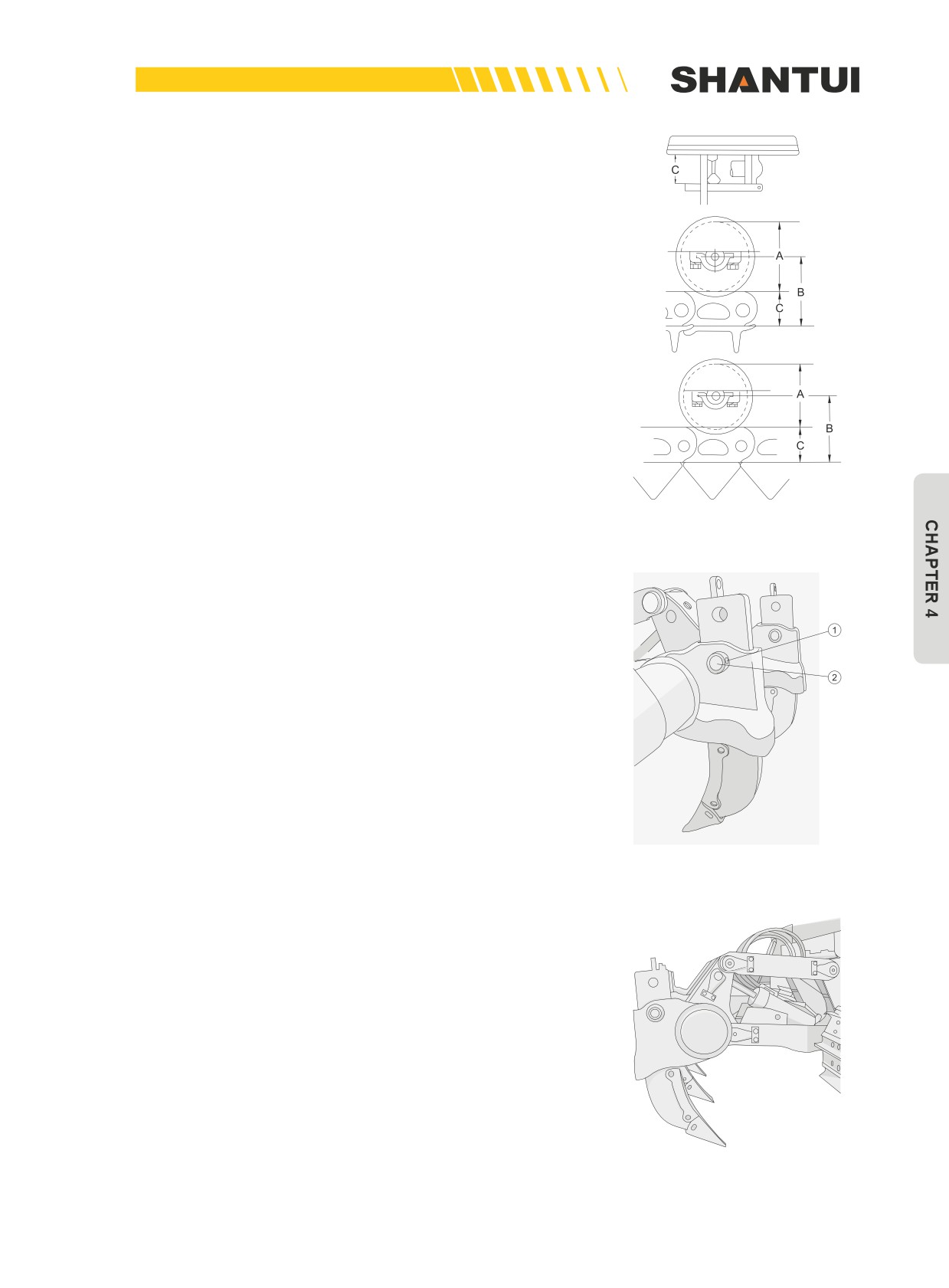
2. Measuring outside diameter of track roller (Figure 4-52)
• Measure the dimensions (size C and B) of link tread as
shown. Calculate outside diameter of track roller (Size A):
A=(B-C)X2
Standard size (A): 222mm
Repair limits (A):198mm
Figure 4-52
Adjustment of blade (See “Chapter 3, Bulldozing Opera-
tion”)
1. Adjustment of the ripper’s ripping depth (Figure 4-53)
• Use the two pin holes on the ripper shank to make the
adjustment, and generally the hole on the bottom is used.
When you need to increase the ripping depth, use the up-
per hole. You can point an iron rod with a sharp end to pin
(1) and hit it with a hammer, and then pull out pin (2), to
change the mounting hole’s position of the tooth angle (top
or bottom).
2. The replacement of the ripper tooth tip and the guard
plate after being worn (Figure 4-54)
• After the ripper tooth tip and the guard plate ripper are
worn, when replacing them, use a hammer to knock out the
Figure 4-53
pins in the figure. You can switch the three tooth tips ac-
cording to their wear level, to extend their service life.
Figure 4-54
179
MAINTENANCE | MAINTENNANCE
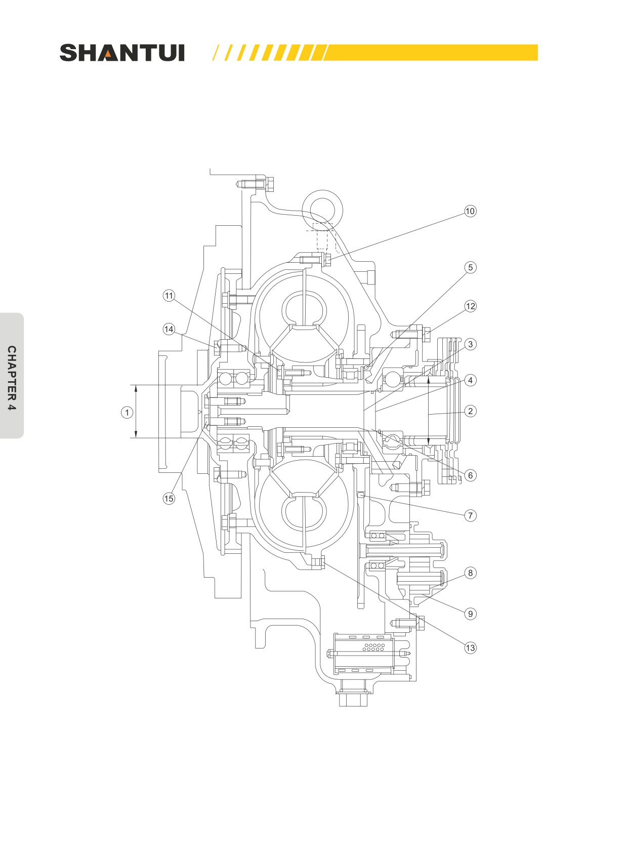
4.1.11 SERVICE STANDARDS FOR MAIN PARTS
HYDRAULIC TORQUE CONVERTER
Figure 4-55
180

MAINTENNANCE | MAINTENANCE
Unit: mm
No.
Items to be checked
Specifications
Measures
Standard
Standard size
Repair limit
The outer diameter of the
clearance
1
guider’s neck
78
—
77.75
The outer diameter of the
2
contact surface of the shaft
105
—
104.9
Chrome
coupling’s oil seal
plating or
The inner diameter of the con-
replacing
3
tact surface of the gear seal-
135
—
135.3
ing ring
The inner diameter of the
4
sealing ring’s contact surface
60
—
60.1
of the guide roller’s axle
The sealing ring of the guide
Width: 4.0;
Width: 3.5;
5
—
roller’s axle
Thickness: 5.2
Thickness: 4.9
The sealing ring of the turbine
Width: 2.5;
Width: 2.0;
6
—
shaft
Thickness: 2.5
Thickness: 2.2
The clearance between the
7
oil scavenger pump’s driving
—
0.16~0.43
0.50
Changing
gear and pump impeller
Oil scavenger pump’s axial
8
—
0.13
0.25
clearance
Oil scavenger pump’s radial
9
—
0.15
0.30
clearance
10
Tightening torque
55±5N.m
11
Tightening torque
70±5N.m
12
Tightening torque
115±10N.m
Adjustment
13
Tightening torque
12±1N.m
14
Tightening torque
115±10N.m
15
Tightening torque
58±2N.m
181
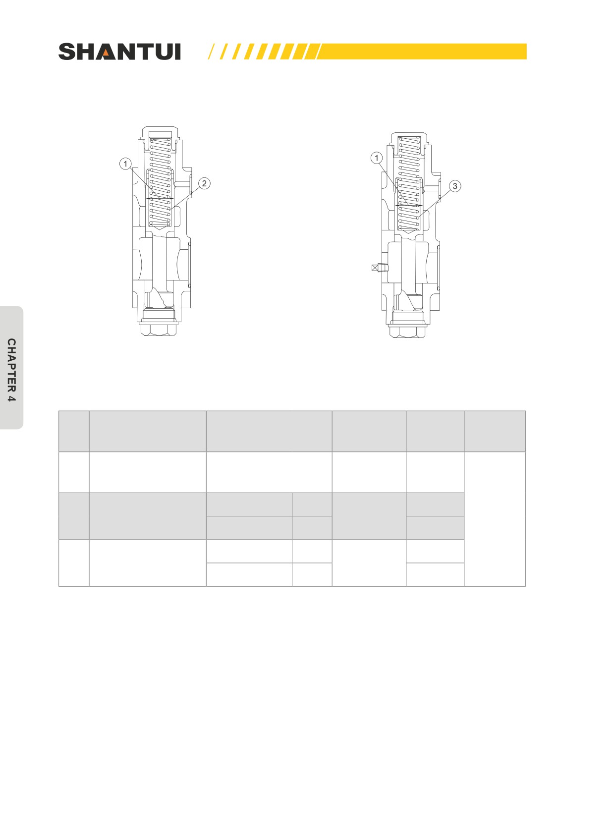
MAINTENANCE | MAINTENNANCE
SAFETY VALVE AND ADJUSTER'S VALVE
Figure 4-56
Unit: mm
Standard
Application
Treatment
No.
Items to be checked
Basic size
clearance
limit
methods
The clearance be-
1
tween valve body and
—
0.05~0.091
0.20
slide valve
Free length
137.7
134.2
2
Safety valve’s spring
—
Replacing
Installation load
635N
579N
Free length
126.6
120
Spring of adjuster’s
3
—
valve
Installation load
209N
140N
182
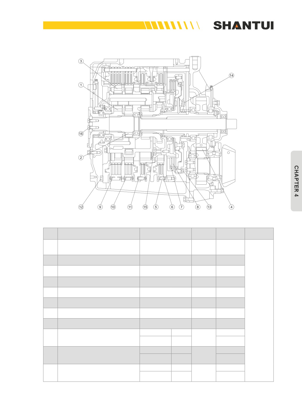
MAINTENNANCE | MAINTENANCE
TRANSMISSION CASE
Figure 4-57
Unit: mm
Standard
Application
Treatment
No.
Items to be checked
Basic size
clearance
limit
methods
The clearance between the No.1,
0.14~
1
No.3 and No.4 sun wheels and
—
—
0.37
the planetary gear
The clearance between the No.2
0.13~
2
—
—
sun wheel and the planetary gear
0.43
The clearance between the gear
0.13~
3
—
—
ring and the planetary gear
0.48
The tooth clearance of the output
0.20~
4
—
—
gear
0.51
The thickness of the driven plate
5
5.4
4.6
of clutches numbers 1 through 4
The thickness of the drive plate
6
7.0
6.2
of clutches numbers 1 through 4
The thickness of the No.5
Replacing
7
5.4
4.6
clutch’s driven plate
The thickness of the No.5
8
5.0
4.2
clutch’s drive plate
Free length
66
64.1
9
The spring of the No.1 clutch
Installation
—
133N
106N
load
Free length
45.7
44.8
10
The spring of the No.2 clutch
Installation
—
96N
77N
load
Free length
45.7
44.5
The spring of the No.3 and No.4
11
—
clutches
Installation
126N
101N
load
183
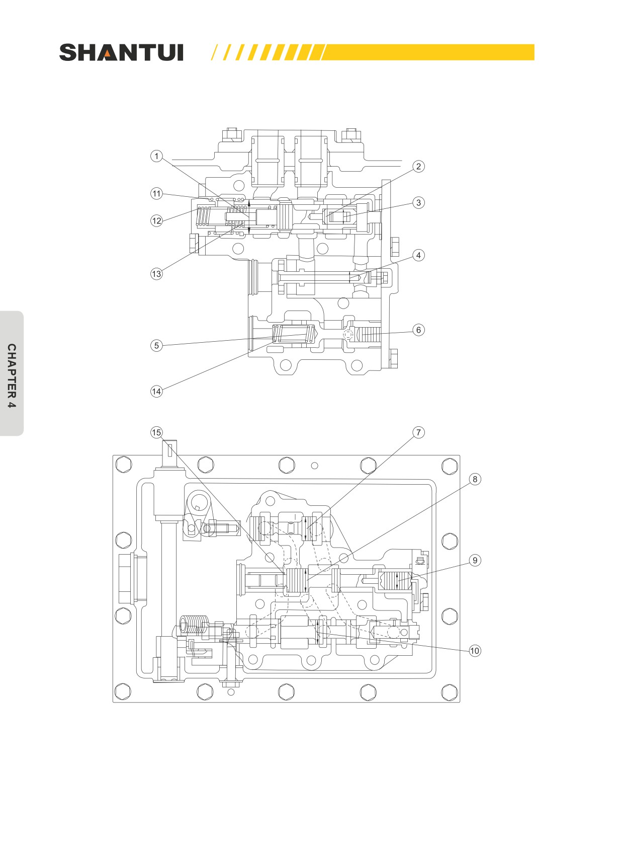
MAINTENANCE | MAINTENNANCE
TRANSMISSION VALVE
Figure 4-58
184
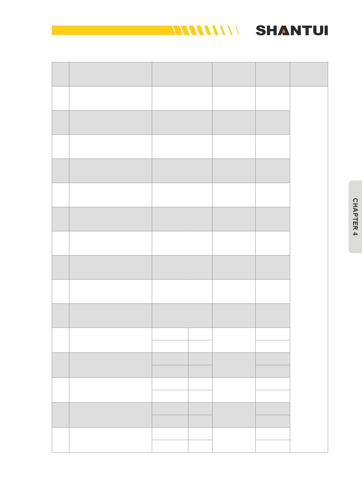
MAINTENNANCE | MAINTENANCE
Unit: mm
Standard
Application
Treatment
No.
Items to be checked
Basic size
clearance
limit
methods
The clearance between the
1
pressure-adjusting valve
—
0.035~0.058
0.064
and valve body
The clearance between the
2
safety valve and the Slave
—
0.035~0.058
0.064
valve
The clearance between the
3
—
0.020~0.048
0.054
safety valve and the piston
The clearance between the
4
fast return valve and valve
—
0.035~0.056
0.062
body
The clearance between the
5
pressure relief valve and
—
0.035~0.058
0.064
valve body
The clearance between the
6
pressure relief valve and
—
0.020~0.048
0.054
the piston
The clearance between the
7
change valve and valve
—
0.035~0.058
0.064
body
The clearance between the
8
—
0.035~0.058
0.064
safety valve and valve body
Replacing
The clearance between the
9
—
0.020~0.048
0.054
safety valve and the piston
The clearance between the
10
—
0.035~0.058
0.064
speed valve and valve body
Free
53
51.2
The pressure-adjusting
length
11
—
valve’s spring
Installation
86.5N
77.9N
load
Free
38.5
37.3
The pressure-adjusting
length
12
—
valve’s spring (big)
Installation
217N
195N
load
Free
43.8
42.6
The pressure-adjusting
length
13
—
valve’s spring (small)
Installation
403N
363N
load
Free
52
50.7
Pressure relief valve’s
length
14
—
spring
Installation
219N
197N
load
Free
79
75.8
length
15
Safety valve’s spring
—
Installation
14.1N
13.4N
load
185
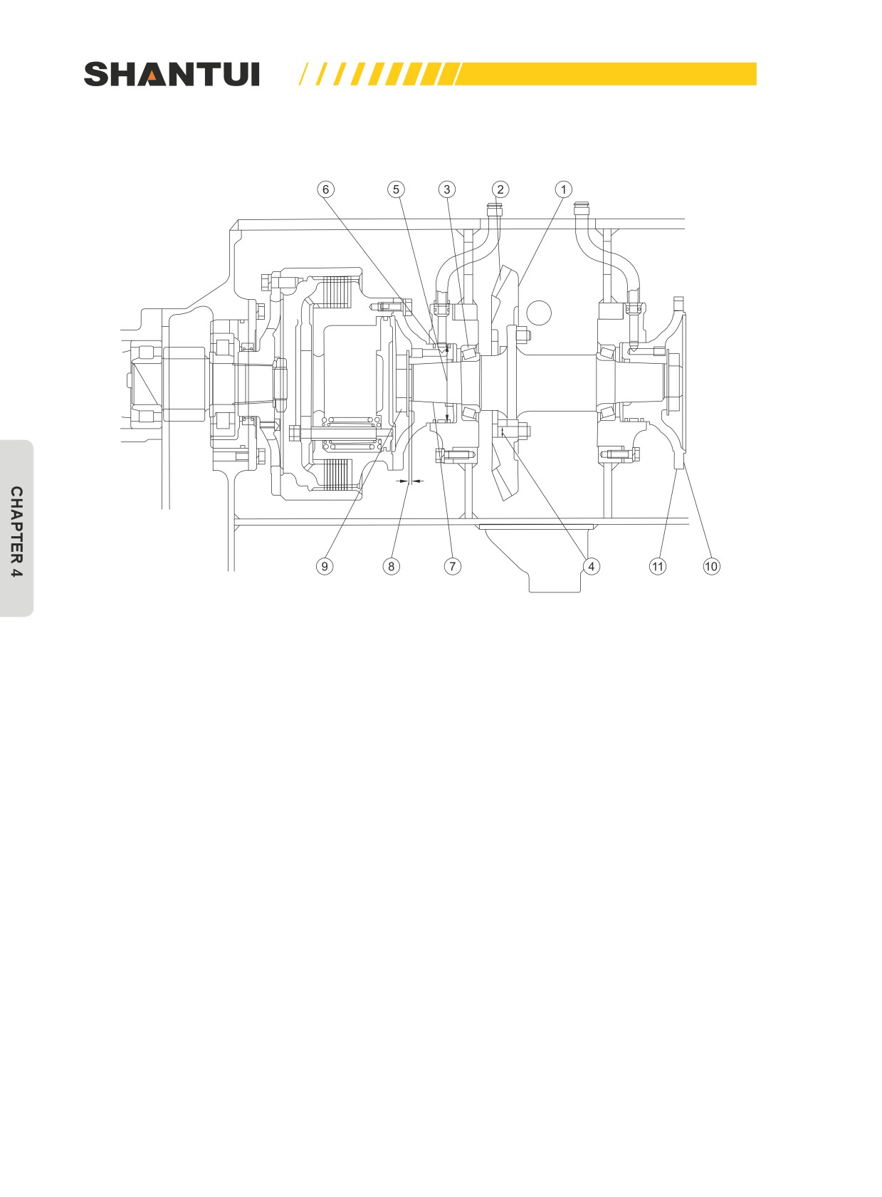
MAINTENANCE | MAINTENNANCE
CENTRAL DRIVE
Figure 4-59
186

MAINTENNANCE | MAINTENANCE
Unit: mm
Standard
Application
Treatment
No.
Items to be checked
Basic size
clearance
limit
methods
0.1 (Mea-
The clearance between the
sured by being
1
pressure-adjusting valve and
—
—
installed be-
valve body
hind the cross
Repairing
shaft)
or
Replacing
The clearance between the
2
—
0.25~0.33
0.75
safety valve and the Slave valve
Rotational torque: 20~30N.m
The clearance between the
3
(Measuring at the end based on the small
Adjustment
safety valve and the piston
bevel gear)
4
The match of bevel gear’s bolt
—
0~0.042
0.1
The inner diameter of the contact
5
surface of the bearing support’s
145
—
145.3
sealing ring
Replacing
The width of the sealing ring
4.5
—
4.0
6
The width of the sealing trough
4.5
—
5.0
The press-in force of the coned
150~300KN
7
—
—
splint
(15~30T)
The size of the central drive shaft
8
6±0.5
—
—
after being pressed in
9
Tightening torque
700±50N.m
—
—
Adjustment
10
The connecting disc’s end jump
—
—
0.03
11
The connecting disc’s radial jump
—
—
0.08
187
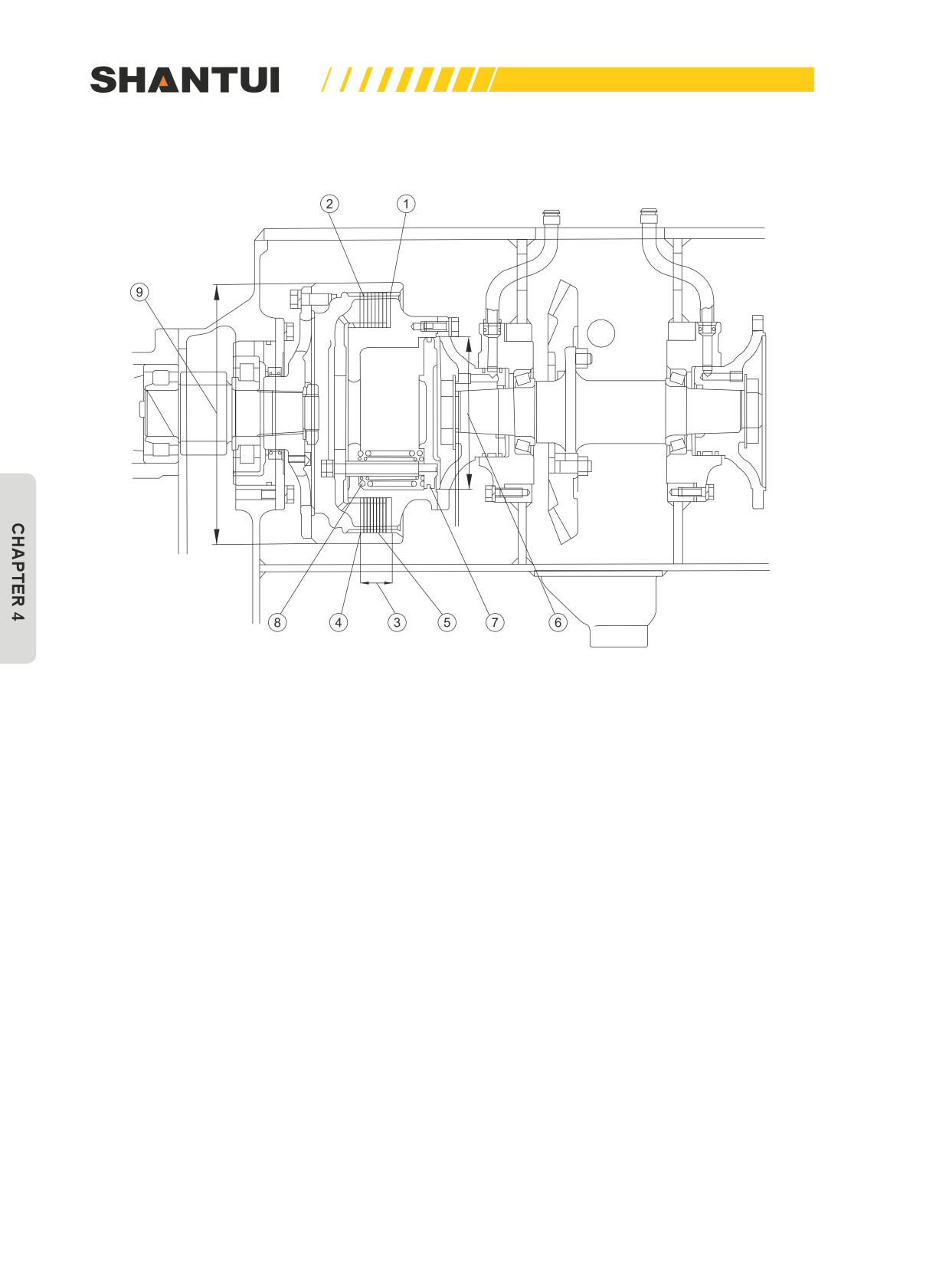
MAINTENANCE | MAINTENNANCE
STEERING CLUTCH
Figure 4-60
188
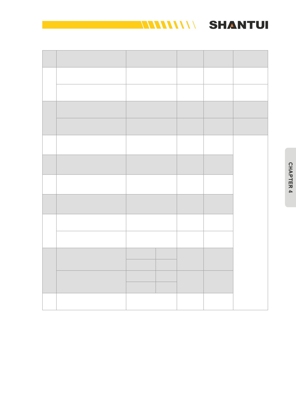
MAINTENNANCE | MAINTENANCE
Unit: mm
Standard
Application
Treatment
No.
Items to be checked
Basic size
clearance
limit
methods
The thickness of the drive
2.9
—
2.0
Replacing
tooth piece
1
The unevenness of the drive
Correction or
<0.20
—
0.3
tooth piece
replacement
The thickness of the driven
4.7
—
3.7
Replacing
tooth piece
2
The unevenness of the
Correction or
<0.20
—
0.3
driven tooth piece
replacement
The thickness of the assem-
3
bly of the drive tooth piece
50.3
—
46
and the driven tooth piece
The tooth clearance be-
4
tween the drive tooth piece
—
0.3~0.4
1.0
and the inner hub
The tooth clearance be-
5
tween the driven tooth piece
—
0.3~0.4
1.0
and the outer hub
The inner diameter of the
6
inner hub and the sealing
245
—
245.3
ring’s contact
The width of the sealing ring
4.9
—
—
Replacing
7
The width of the sealing
5
—
—
trough
Free
145.15
141
length
Spring (big)
—
Installation
2291N
2420N
load
8
Free
137.83
length
146.5
Spring (small)
—
Installation
1320N
1380N
load
The diameter of the outer
9
425
—
420
hub
189
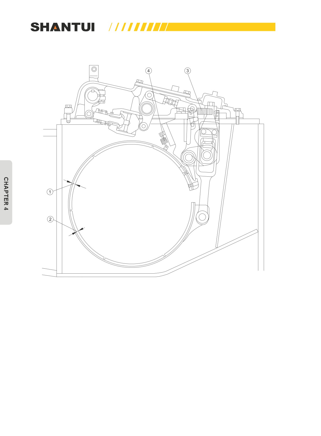
MAINTENANCE | MAINTENNANCE
BRAKE
Figure 4-61
190
MAINTENNANCE | MAINTENANCE
Unit: mm
Standard
Application
Treatment
No.
Items to be checked
Basic size
clearance
limit
methods
The thickness of the brake
1
14
—
9.5
lining and the brake band
The thickness of the brake
2
9.5
—
5
lining
Replacing
Free length
78.3
82
3
Spring
—
Installation load
200N
160N
Free length
42.4
43.3
4
Spring
—
Installation load
45.4N
36N
191
MAINTENANCE | MAINTENNANCE
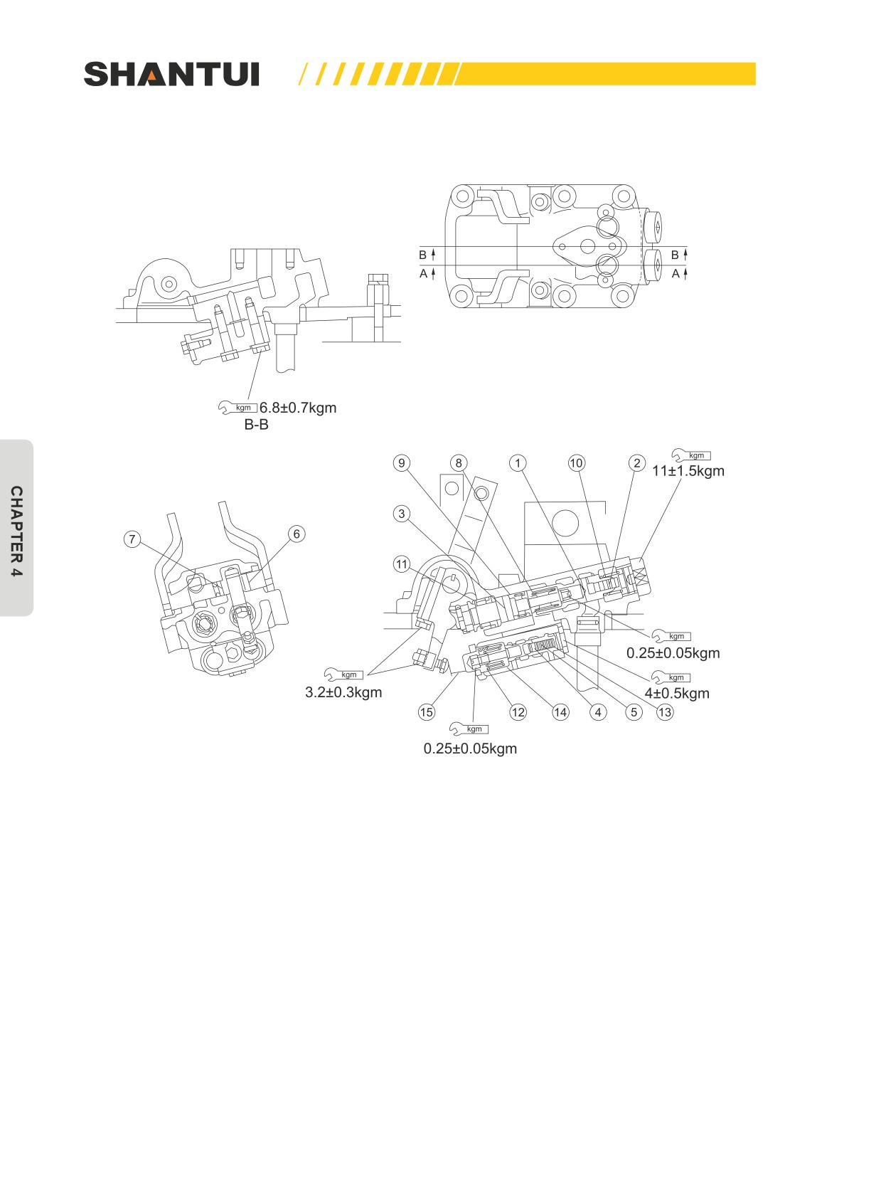
STEERING CONTROL VALVE
Figure 4-62
192
MAINTENNANCE | MAINTENANCE
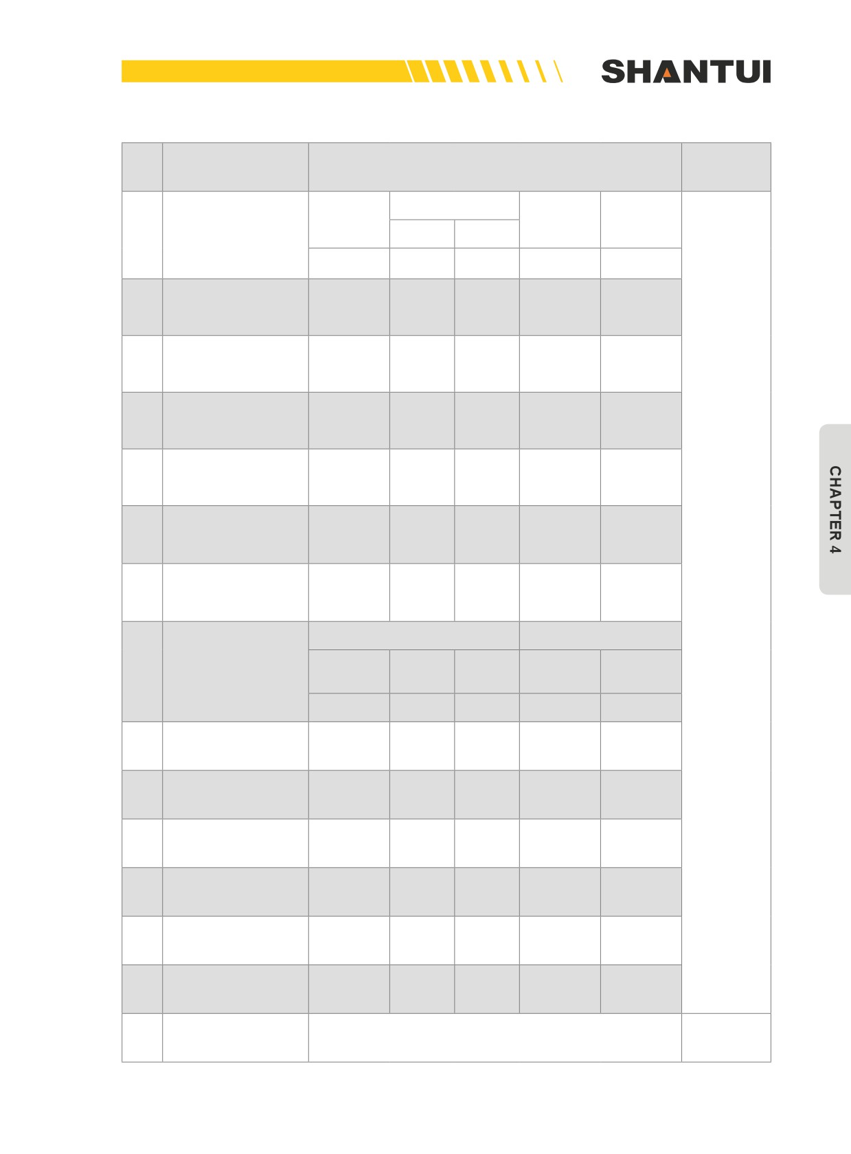
Unit: mm
Items to be
No.
Specifications
Measures
checked
Tolerance
Standard
Standard
Allowable
The clearance
size
clearance
limit
1
between valve body
Shaft
Hole
and valve core
-0.035
+0.013
0.035~
26
0.08
-0.045
0
0.058
The clearance
-0.030
+0.015
0.030~
2
between the valve
10
0.08
-0.040
0
0.055
core and the piston
The clearance
-0.035
+0.013
0.035~
3
between valve stem
26
0.08
-0.045
0
0.058
and valve body
The clearance be-
-0.030
+0.018
0.030~
4
tween brake valve
16
0.08
-0.035
0
0.053
and valve body
The clearance be-
-0.030
+0.015
0.030~
5
tween brake valve
9
0.08
-0.040
0
0.055
and piston
The clearance
between the control
+0.023
+0.170
0.068~
6
22
0.2
lever and the bush-
+0.002
+0.086
0.168
ing
The clearance
between the control
+0.019
+0.156
0.067~
7
18
0.2
lever and the bush-
+0.001
+0.086
0.155
Replacing
ing
Standard size
Repair limit
Instal-
Instal-
Free
Free
8
Axle reset spring
lation
lation
Load
length
length
length
load
36
27.2
6.02kg
35.3
5.7kg
Steering valve
9
62
15.8
3.5kg
60.9
3.2kg
spring
Steering valve reset
10
91.6
25
4.53kg
90.6
4.3kg
spring
Steering valve
11
55
20.5
3.61kg
54
3.3kg
spring
Brake adjusting
12
28.5
25.5
3.0kg
28
2.8kg
spring
Brake valve reset
13
50.5
14
2.36kg
49.5
2.2kg
spring
Brake valve reset
14
90
27
4.48kg
88.5
4.15kg
spring
Brake valve’s action
15
13.7
Adjustment
trip
193