Shantui SD22. Operation and Maintenance Manual - 6
MAINTENANCE | MAINTENNANCE
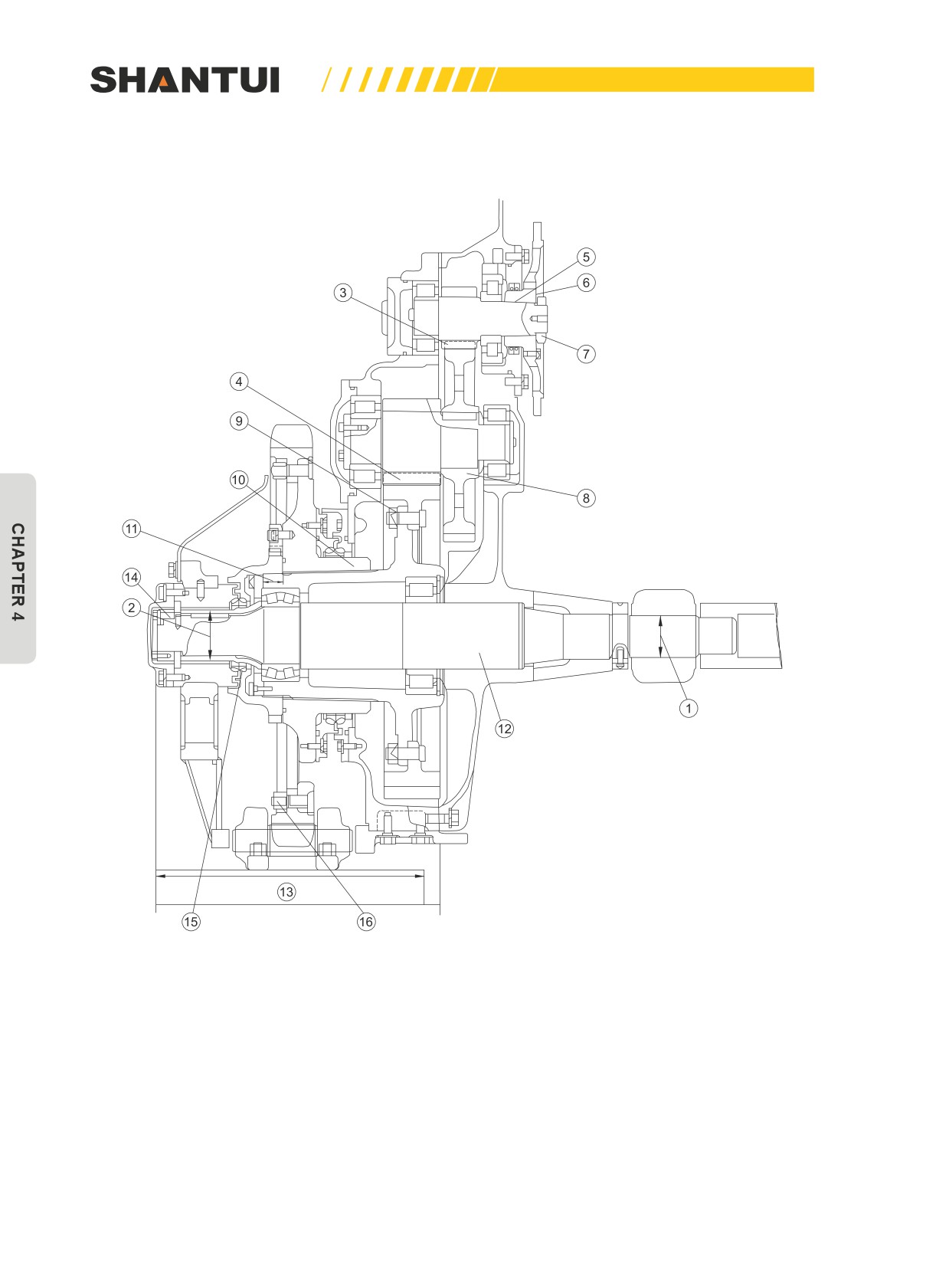
FINAL DRIVE
Figure 4-63
194

MAINTENNANCE | MAINTENANCE
Unit: mm
Basic
Standard
Application
Treatment
No.
Items to be checked
size
clearance
limit
methods
The clearance between the half
1
—
0.036~0.106
0.5
shaft and the bushing
Replacing
Bushing
The clearance between the half
2
—
0.12~0.270
0.5
shafts out bushing and spacer
Primary gear’s engagement back-
3
—
0.40~0.623
1.5
lash
Replacing
Secondary gear’s engagement
4
—
0.48~0.85
1.5
backlash
5
Press-in force
300 ~ 400KN (30 ~ 40t)
Size of the drive disc after being
6
2~3.5
pressed in
7
Nut’s tightening torque
700±50Nm
8
Press-in force
50 ~ 160KN (5 ~ 40t)
Size of the sprocket hub after be-
9
39~41
ing pressed in
10
Press-in force
500 ~ 600KN (50 ~ 40t)
Adjustment
Size of the sprocket hub after be-
11
39~41
ing pressed in
12
Press-in force
120 ~ 460KN (12 ~ 40t)
Size of half shaft’s end surface and
13
599.9(SD22S is 724.5)
steering case
14
Nut’s tightening torque
1050±150Nm
15
Sprocket nut’s tightening torque
1050±150Nm
16
Nut’s tightening torque
950~1150Nm
195
MAINTENANCE | MAINTENNANCE
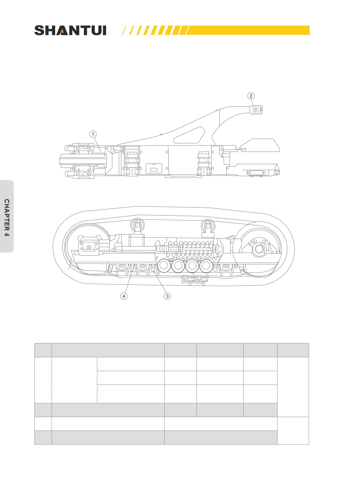
TRACK
1. TRACK FRAME
s
D
s s s D
s
Figure 4-64
Unit: mm
Basic
Standard
Application
Treatment
No.
Items to be checked
size
clearance
limit
methods
Horizontal deforma-
—
—
7/300
tion
Deformation
Twisted
—
—
3/300
1
Repair-
of track frame
The place where the
ing and
idler is installed is
—
—
5
changing
outwardly opened
The clearance between the half shaft
2
—
0.036~0.106
0.5
and the bushing
3
Tightening torque
760±85N.m
Adjust-
ment
4
Tightening torque
825±225N.m
196
MAINTENNANCE | MAINTENANCE
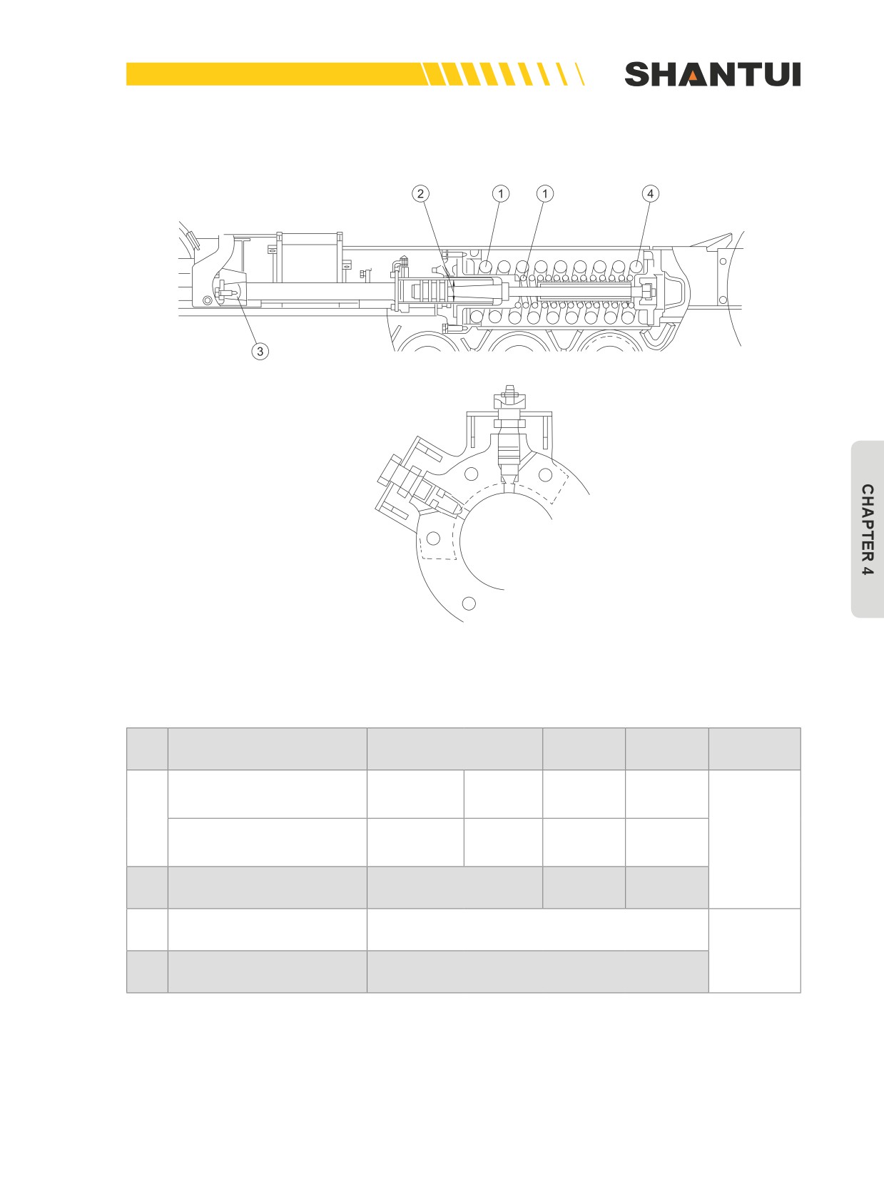
2. TRACK TENSION DEVICE
Figure 4-65
Unit: mm
Standard
Application
Treatment
No.
Items to be checked
Basic size
clearance
limit
methods
Free length
817
Buffering spring (big)
Installation
—
154000N
171300N
load
1
Free length
530
Buffering spring (small)
Installation
—
29000N
Replacing
load
32500N
0.101~
The clearance between oil
3
—
0.5
cylinder and bushing
0.226
Tension rod assembly’s
4
150KN (15t)
press-in force
Adjustment
The clearance between
5
10
control seat and nut
197
MAINTENANCE | MAINTENNANCE
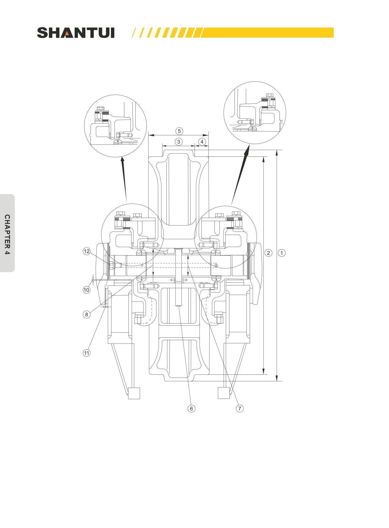
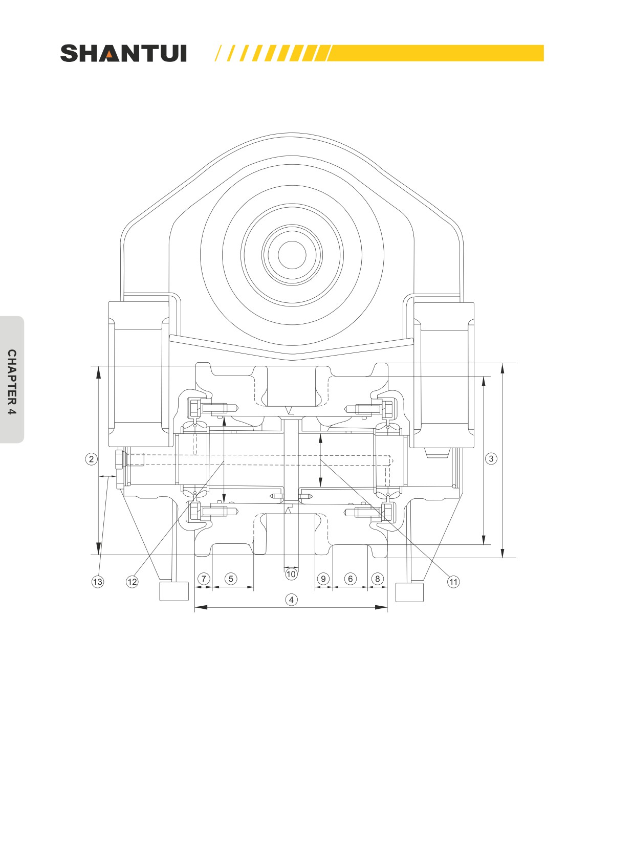
3. IDLER
Figure 4-66
198

MAINTENNANCE | MAINTENANCE
Unit: mm
Basic
Standard
Application
Treatment
No.
Items to be checked
size
clearance
limit
methods
1
Idler’s outer diameter
774
—
760
Roller track surface’s outer diam-
2
730
—
715
eter
Repairing
through over-
3
Width of the raised part
105
—
89
lay welding
or replacing
4
Width of the roller track
49.5
—
51.5
5
Overall width
204
—
194
6
Shaft collar’s width
20
—
19.5
The clearance between the shaft
7
—
0.270~0.390
1.5
and the dual-metal bushing
The interference between the idler
8
—
-0.03~-0.144
-0.35
and the bushing
Replacing
The axial clearance of the idler’s
9
—
0.27~0.39
1.5
axle
The clearance between the sliding
10
—
2
—
plate and the bracket
The clearance between the side
11
—
0.5~1.0
3
guide and the bracket
12
Tightening torque
210±5N.m
Adjustment
199
MAINTENANCE | MAINTENNANCE
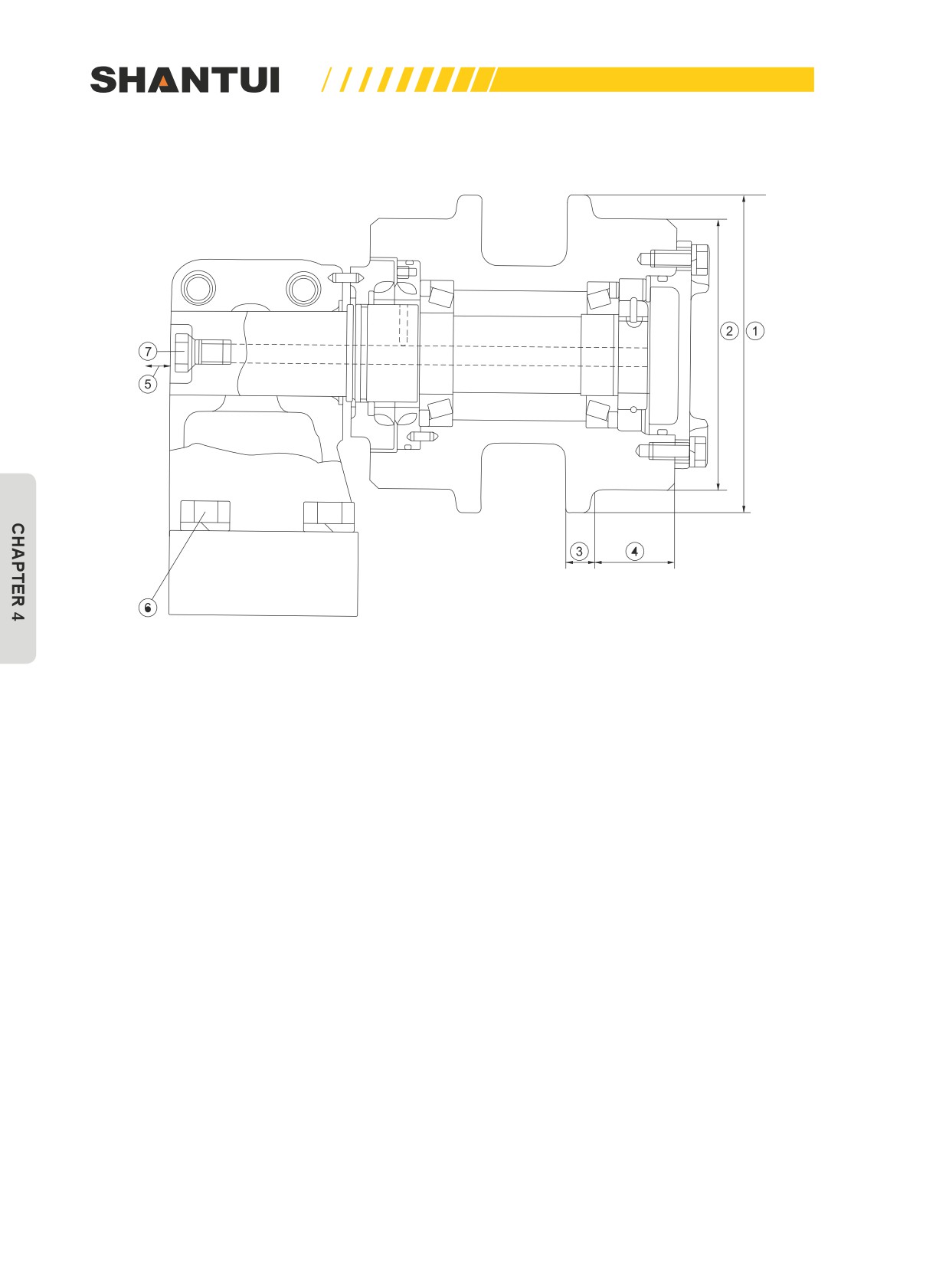
4. SINGLE FLANGE TRACK ROLLER, DOUBLE FLANGE TRACK ROLLER
Figure 4-67
200

MAINTENNANCE | MAINTENANCE
Unit: mm
Basic
Standard
Application
Treatment
No.
Items to be checked
size
clearance
limit
methods
The outer diameter of the track
1
257
—
247
roller
The outer diameter of the track
2
249
—
239
roller
3
Roller track surface’s diameter
222
—
198
4
Overall width
251.2
—
—
Repairing
The width of the roller track of the
through over-
5
55.6
—
66.6
single flange track roller
lay welding
or replacing
The width of the roller track of the
6
51.6
—
68.6
double flange track roller
The width of the raised shoulder of
7
21
—
6
the single flange track roller
The width of the raised shoulder of
8
21
—
6
the double flange track roller
The width of the raised shoulder of
9
21
—
6
the double flange track roller
10
Shaft collar’s width
20
—
18.5
The clearance between the shaft
11
—
0.31~0.39
1.0
and the dual-metal bushing
Replacing
The interference between the
12
—
-0.013~-0.121
-0.35
bushing and the track roller
The axial clearance of the track
13
—
0.40~0.80
1.5
roller’s axle
201
MAINTENANCE | MAINTENNANCE
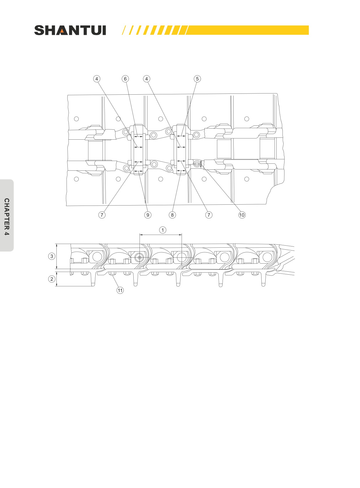
5. CARRIER ROLLER
Figure 4-68
202

MAINTENNANCE | MAINTENANCE
Unit: mm
Standard
Application
Treatment
No.
Items to be checked
Basic size
clearance
limit
methods
The outer diameter of the carrier
1
217
—
207
roller
The outer diameter of the roller
2
185
—
166
track
Repairing
through over-
lay welding
or replacing
3
The width of the raised shoulder
19
—
10
4
The width of the roller track
57
—
66
The axial clearance of the carrier
Adjusting or
5
—
0.10~0.13
0.2
roller
Replacing
6
Tightening torque
560±60N.m
Adjustment
7
Tightening torque
210±50N.m
203
MAINTENANCE | MAINTENNANCE
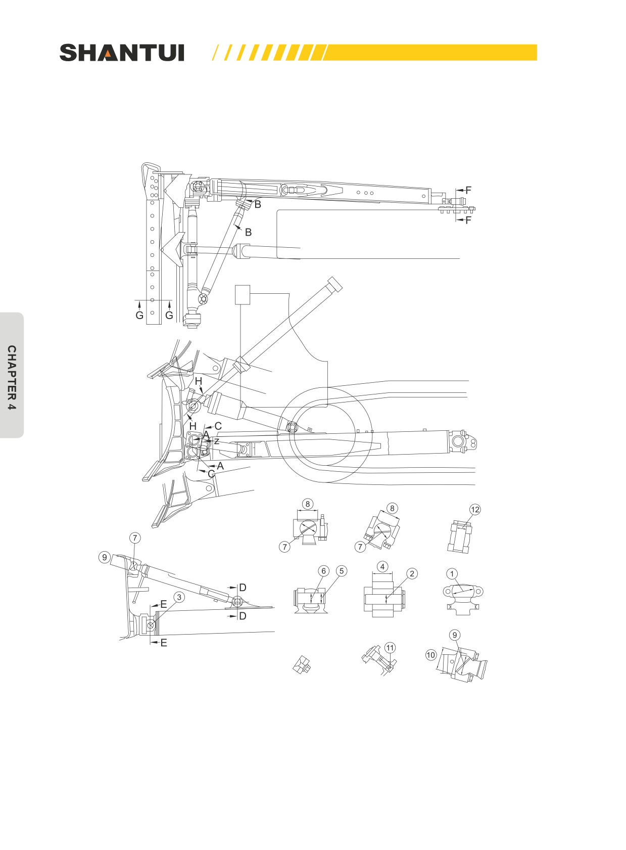
6. TRACK
Figure 4-69
204

MAINTENNANCE | MAINTENANCE
Unit: mm
Standard
Application
Treatment
No.
Items to be checked
Basic size
clearance
limit
methods
1
Track link
216.25
—
219.25
72
25
Inverting or
2
Grouser’s height
—
123(SD22S)
101
replacing
3
Track link’s height
129
—
117
4
Bushing’s outer diameter
74.3
—
70.8
The clearance between the pin
5
—
0.230~0.830
—
and the bushing
The clearance between the
6
—
0.430~1.030
—
master pin and the bushing
The interference between the
7
—
0.230~0.344
0.22
Replacing
bushing and the track link
The interference between the
8
—
0.023~-0.185
0.203
pin and the track link
The interference between the
9
—
0.138~0.230
0.138
master pin and the track link
One-sided:
The clearance of the track link’s
0~1.1
10
—
8
joint surface
Two-sided:
0~2.2
11
Tightening torque
0.5~1.0
3
Adjustment
205
MAINTENANCE | MAINTENNANCE
STRAIGHT TILT BLADE
1. BLADE
Section A-A Section B-B
Section C-C
Section D-D
Section E-E
Section F-F
Section G-G
Section H-H
View Z
Figure 4-70
206

MAINTENNANCE | MAINTENANCE
Unit: mm
Basic
Standard
Application
Treatment
No.
Items to be checked
size
clearance
limit
methods
The clearance between the seat
1
—
0.5~0.15
10
and the spherical head
The clearance between the pin and
2
—
0.3~0.8
3
the blade rack’s connector
The clearance between the push
3
—
0.3~0.8
3
rod’s pin and the connector
The clearance between the con-
4
—
0.3~1.1
6
nector and the blade rack
The clearance between the pin and
5
—
0.5~1.0
2
the seat
The clearance between the pin and
6
—
0.6~1.0
2
the screw
Replacing
The clearance between the spheri-
7
—
0.2~0.6
1
cal head and the seat
The clearance between the cover
8
—
0.1~-0.4
and the spherical seat
The clearance between the spheri-
9
—
0.2~0.6
1
cal head and the seat
The clearance between the cover
10
—
0.046~0.206
and the spherical seat
The clearance between the pin and
11
—
0.4~0.8
2
the seat
The clearance between the bracket
12
—
0.3~0.7
1
and the pin
207
MAINTENANCE | MAINTENNANCE
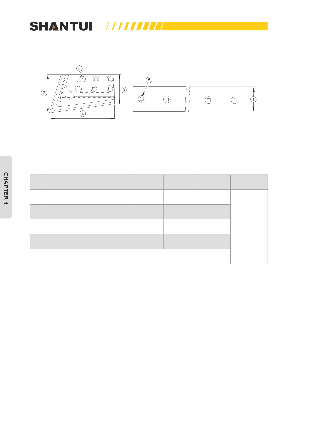
2. END BIT AND CUTTING EDGE
Figure 4-71
Unit: mm
Basic
Standard
Application
Treatment
No.
Items to be checked
size
clearance
limit
methods
1
The cutting edge’s height
254
—
213
2
The height of end bit’s outer side
292
—
211
Replacing
3
The height of end bit’s inner side
254
—
211
4
End bit’s width
435
—
360
5
Tightening torque
540±80N.m
Adjustment
208
MAINTENNANCE | MAINTENANCE
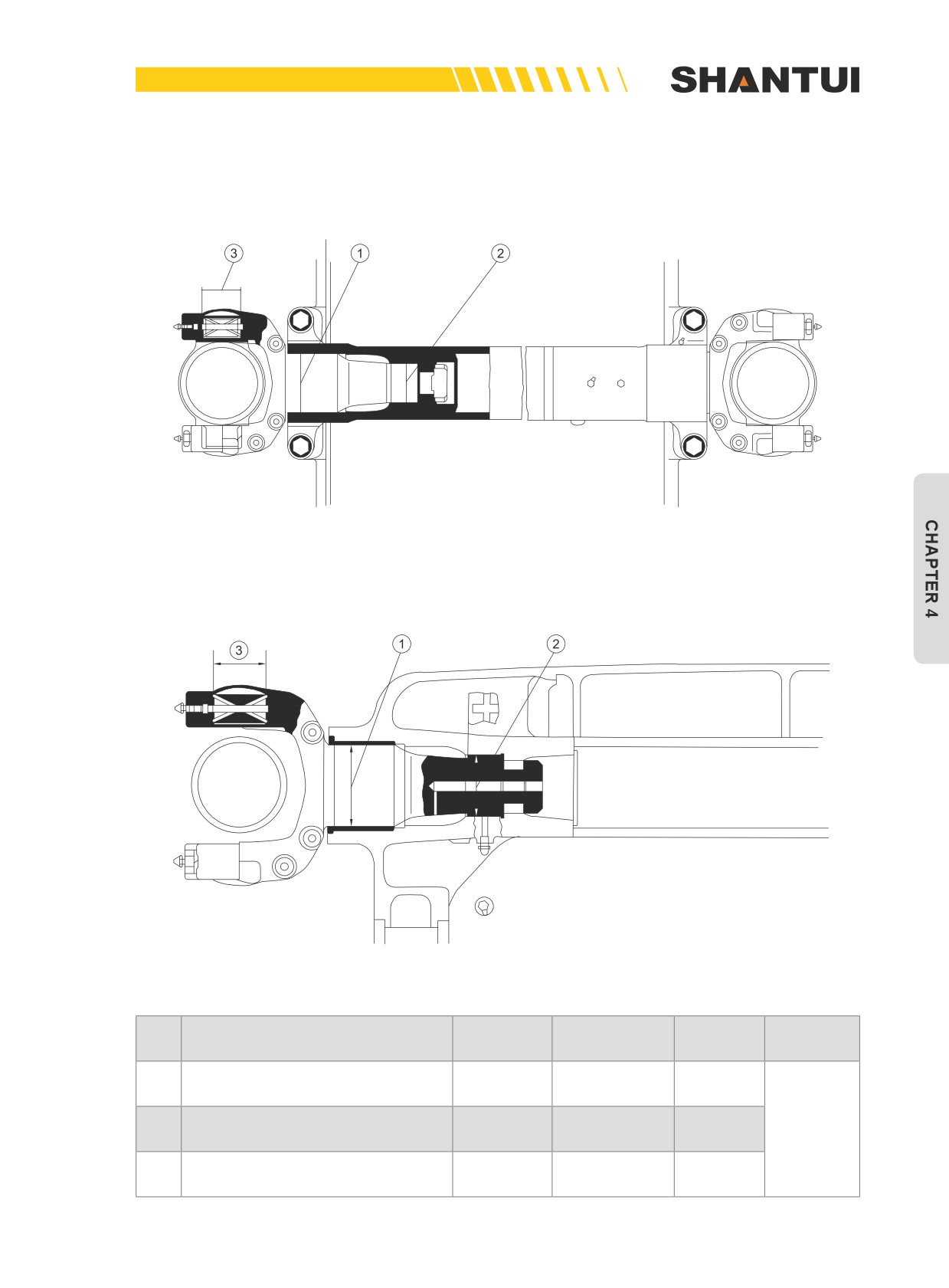
OIL CYLINDER BRACKET
1. OIL CYLINDER BRACKET OF SD22, SD22E AND SD22D
Figure 4-72
2. OIL CYLINDER BRACKET OF SD22S
Figure 4-73
Unit: mm
Standard
Application
Treatment
No.
Items to be checked
Basic size
clearance
limit
methods
The clearance between the shaft
1
—
0.072~0.180
0.5
and the bushing
The clearance between the shaft
2
—
0.060~0.152
0.5
Replacing
and the bushing
The clearance between the shaft
3
—
0~0.074
0.5
and the bushing
209
MAINTENANCE | MAINTENNANCE
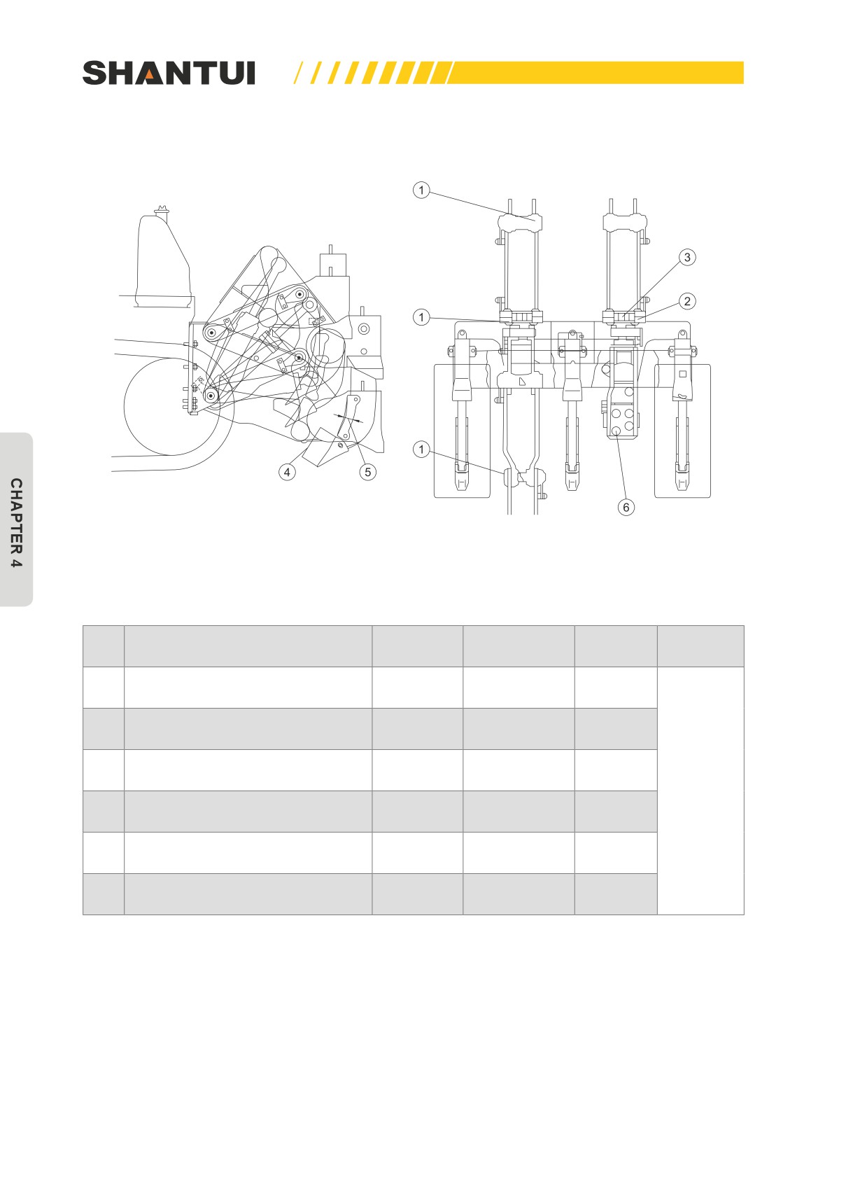
RIPPER
Figure 4-74
Unit: mm
Standard
Application
Treatment
No.
Items to be checked
Basic size
clearance
limit
methods
The clearance between the circular
1
—
0.230~0.476
1.5
pin and the bushing
The clearance between the tooth
2
—
1.4~2.6
10
rack’s hole and the pin
The clearance between the pin and
3
—
3.7~6.5
15
the rack hole
Replacing
4
The wearing of the tooth tip
335
—
225
5
The wearing of the tooth sleeve
75
—
55
6
Tightening torque
2250±250N.m
210
MAINTENNANCE | MAINTENANCE
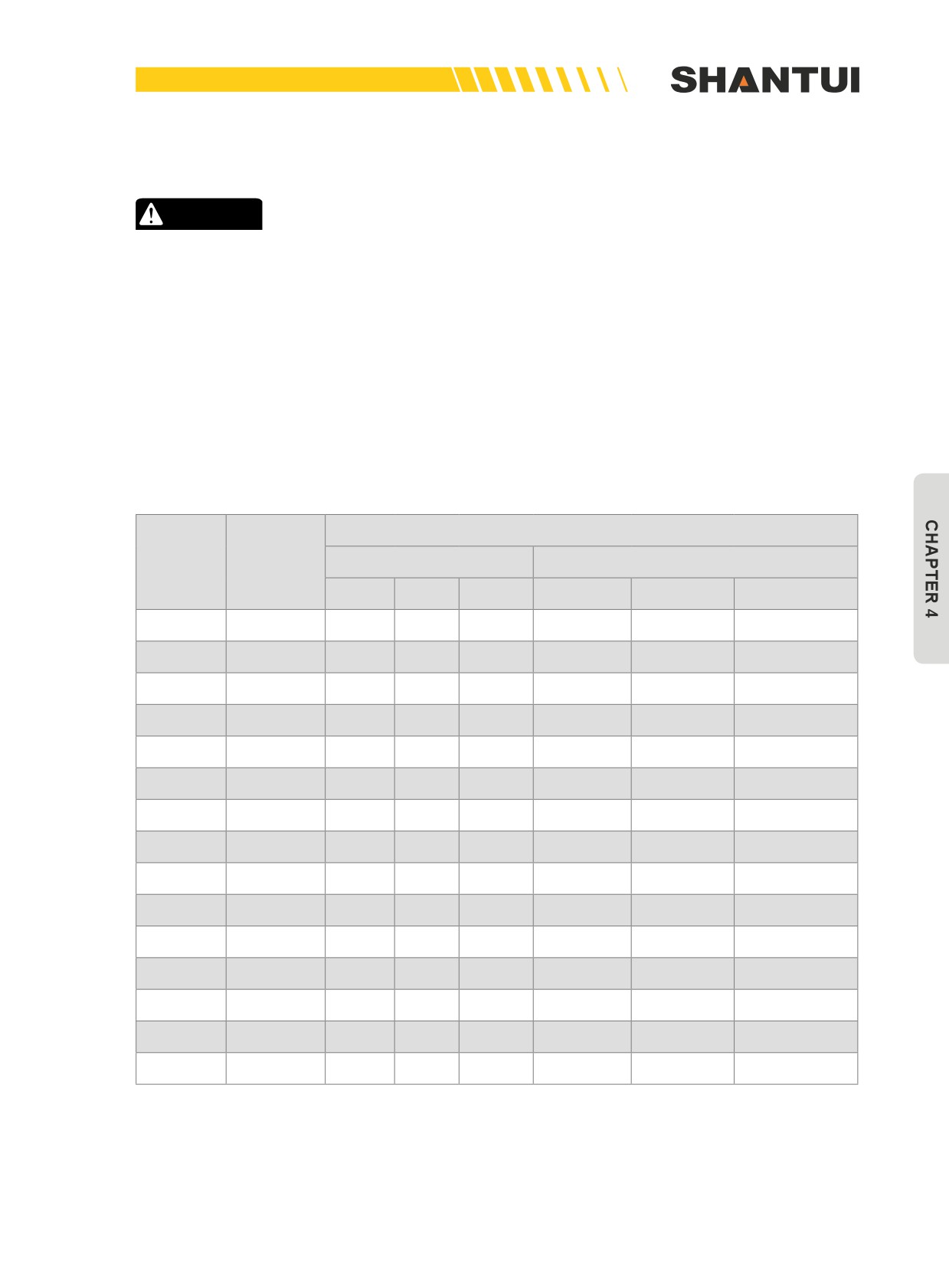
4.1.12 STANDARD TIGHTENING TORQUES FOR BOLTS AND NUTS
CAUTION
• If nuts, bolts, or other parts are not tightened to the specified torque, it will cause loose-
ness or damage to the tightened parts, and this will cause failure of the machine or prob-
lems with operation.
• Always pay careful attention when tightening parts.
TORQUE LIST
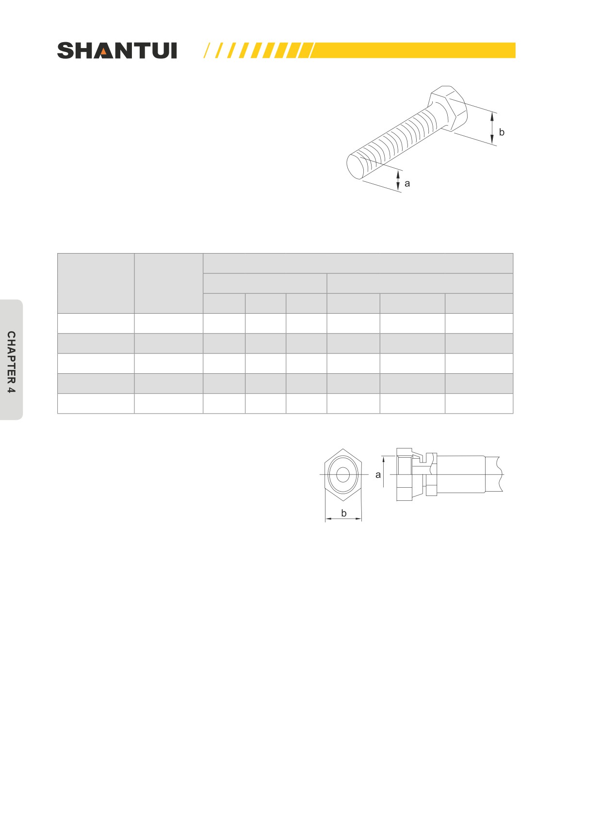
1. Unless otherwise specified, tighten the metric nuts and bolts to the torque shown in the table be-
low.
• If it is necessary to replace any nut or bolt, always use a Shantui genuine part of the same size
as the part that was replaced.
Specifications
Thread
Width
diameter
across
Target value
Torque range
of bolt (a)
flats (b)
(mm)
(mm)
N.m
kgf.m
ibft
N.m
kgf.m
ibft
6
10
13.2
1.35
9.8
11.8-14.7
1.2-1.5
8.7-10.8
8
13
31
3.2
23.1
27-34
2.8-3.5
20.3-25.3
10
17
66
6.7
48.5
59-74
6.0-7.5
43.4-54.2
12
19
113
11.5
83.2
98-123
10.0-12.5
72.3-90.4
14
22
172
17.5
126.6
153-190
15.5-19.5
112.1-141
16
24
260
26.5
191.7
235-258
23.5-29.5
170.0-213.4
18
27
360
37
267.6
320-400
33.0-41.0
238.7-296.6
20
30
510
52.3
378.3
455-565
46.5-58.5
336.3-419.5
22
32
688
70.3
508.5
610-765
62.5-78.0
452.1-564.2
24
36
883
90
651
785-980
80.0-100.0
578.6-723.3
27
41
1295
132.5
958.4
1150-1440
118.0-147.0
853.5-1063.3
30
46
1720
175.0
1265.8
1520-1910
155.0-195.0
1121.1-1410.4
33
50
2210
225.0
1627.4
1960-2450
200.0-250.0
1446.6-1808.3
36
55
2750
280.0
2025.2
2450-3040
250.0-310.0
1808.3-3242.2
39
60
3280
335.0
2423.1
2890-3630
295.0-370.0
2133.7-2676.2
211
MAINTENANCE | MAINTENNANCE
2. Tighten the hydraulic hoses according to the tightening torque in the table below
Specifications
Thread
Width
diameter of
across flats
Target value
Torque range
bolt (a)(mm)
(b)(mm)
N.m
kgf.m
ibft
N.m
kgf.m
ibft
9/16-18UNF
19
44
4.5
32.5
35-63
3.5-6.5
25.3-47.0
11/16-16UN
22
74
7.5
54.2
54-93
5.5-9.5
39.8-68.7
13/16-16UN
27
103
10.5
75.9
84-132
8.5-13.5
61.5-97.6
1-14UNS
32
157
16
115.7
128-186
13.0-19.0
94.0-137.4
13/16-12UN
36
216
22
159.1
177-245
18.0-25.0
130.2-180.8
212
MAINTENNANCE | TROUBLESHOOTING
4.2 TROUBLESHOOTING
Although not all the faults are included in this chapter, most common faults are included.
4.2.1 ENGINE
Engine oil pressure monitor flashes when
Engine does not start when starting motor
engine speed is raised after completion of
is turned
warm-up.
1. Add fuel;
1. Add oil to specified level;
2. Check if air has entered the fuel system;
2. Replace engine oil filter element;
3. Calibrate or replace oil pump and oil noz-
3. Check the tubes and connectors for oil
zle;
leakage.
4. Check valve clearance;
5. Run the starting motor at a low speed (See
Steam is emitted from top part of radiator
ELECTRIC SYSTEM).
(pressure valve).
1. Add cooling water, and check for water
Exhaust gas is white or blue
leakage;
1. Add oil to specified level;
2. Adjust fan belt’s tension;
2. Change to specified fuel;
3. Clean inside of cooling system;
3. Check supercharger for leakage.
4. Clean or repair the water tank’s radiation
fin;
Exhaust gas turns black
5. Replace thermostat.
1. Clean or replace air filter;
6. Tighten radiator cap or replace its gasket.
2. Replace oil nozzle;
3. Clean or replace supercharger.
Water temperature is higher than 100°C.
1. Replace thermostat;
Abnormal noise generated (combustion or
2. Check water temperature sensor ;
mechanical)
3. Check water temperature gauge and water
1. Change to specified fuel;
temperature sensor.
2. Check if the engine is overheated;
3. Replace muffler;
4. Adjust valve clearance.
213
TROUBLESHOOTING | MAINTENNANCE
4.2.2 ELECTRIC SYSTEM
4.2.3 CHASSIS
Lamp does not glow brightly even when the
Oil pressure in torque converter fails to rise
engine runs at high speed.
(the vehicle cannot start to move)
1. Check, repair loose terminals, disconnec-
1. Check and repair oil pipes or connectors
tions;
for air leakage;
2. Adjust engine belt tension.
2. Check or replace gear pump;
3. Add oil to transmission case;
When the engine runs at a high speed, volt-
4. Clean and replace transmission case’s fil-
meter indicates not charging (not within the
ter.
green zone)
1. Check generator;
The hydraulic torque converter is overheat-
2. Check and repair circuit.
ed
1. Tighten or replace fan belt.
Abnormal noise is generated from alterna-
2. See the ENGINE part.
tor
3. Clean or replace oil cooler.
Replace generator.
4. See the “Oil pressure in torque converter
Starting motor does not crank when igni-
fails to rise” part.
tion switch is turned ON.
The vehicle does not move when gear shift
1. Check and repair circuit and relay;
lever in any position
2. Charge the battery;
1. Add oil to the steering clutch case.
3. Replace starting motor.
2. See the “Oil pressure in torque converter
fails to rise” part.
Pinion of starting motor keeps going in and
3. Check or replace gear pump.
out
4. Clean oil filter.
1. Charge the battery;
2. Replace starting motor.
When pull the steering lever on one side,
the vehicle continues to move forward with-
Starting motor disengages before engine
out steering.
starts
• Adjust brake.
1. Check and repair circuit ;
2. Charge the battery.
Machine doesn't stop when brake pedal are
depressed.
When the engine stops (starting switch is
• Adjust brake.
in the “ON” position, engine oil pressure
gauge is 0.
Track comes off
1. Replace engine oil pressure sensor;
• Sprocket is abnormally worn
2. Check and repair circuit.
• Adjust track tension
Blade rises too slowly or does not rise at all
• Add oil to the hydraulic tank
214
MAINTENNANCE | PRECAUT. FOR DISASSEMBLY & ASSEMBLY
4.3 PRECAUTIONS FOR DISASSEMBLY AND ASSEMBLY
4.3.1 DISASSEMBLY
1. Before disassembling bulldozer’s any part, read the manual carefully, so that you have a thor-
ough understanding of the parts to be disassembled. Knowing the structure and role of various
parts is an important factor in successfully performing the servicing.
2. During disassembly, pay adequate attention to the direction and position of every part. If neces-
sary, make the identification marks. Meanwhile, pay attention to the sequence of removing vari-
ous parts from the bulldozer, to ensure the correct installation of the parts.
3. Use special tools required. If you don’t have special tools, use similar ones. When ordinary tools
can damage related parts in one way or another, you must use special tools.
4. Tapered or closely matched parts should be closely installed in their original places. If these
parts are already loose, check their wear.
5. The removed parts should be cleaned and orderly put together. Measures should be taken so
that they will not be covered by dust. Two types of cleaning liquids should be used: one for
washing away the dirty things, and another for rinsing.
CAUTION
Filters, magnetic plugs and breather covers are all parts that you should pay special atten-
tion to when washing and cleaning them
215
PRECAUT. FOR DISASSEMBLY & ASSEMBLY | MAINTENNANCE
4.3.2 ASSEMBLY
1. All the parts should be clean before being assembled. Replacement parts are usually covered
with anti-rust agent, and you should wipe off the anti-rust agent first.
2. In most cases, the installation of bearings, bushing, oil seals and other similar parts should use
the special installation tools. Using a hammer to directly knock a part into place is a bad habit.
Usually, you need to put a wood block or soft metal part beneath the part to be installed to trans-
mit the impact from the hammer.
3. Spring washers, flat washers, tongue washers and cotter pins are all very important parts. But
because of their small size, they are easy to be missed out during assembly. When installing
fasteners such as bolts and nuts, check the tightening methods of these parts for compliance.
4. A torque wrench should be used in places where the torque limit is specified. When fixing cov-
ers or similar parts with many bolts (such as valve body etc), tighten the bolt symmetrically and
gradually, to let the pressure be evenly distributed.
5. The matching markings are not the identification markings for parts that go with each other, and
instead they represent a way to show that you should align them as much as possible. Never
misunderstand them.
4.3.3 ASSEMBLY AND DISASSEMBLY OF BEARINGS
1. Dust is harmful to all the bearings. Dust is often the cause of the noise from bearings and the
cause for the accelerated deterioration of lubricant. When replacing bearings, you can only open
the package of the bearings after all the other installation work has been completed.
2. Use gasoline as the cleansing liquid for bearings. If you have access to the compressed air, you
can also use kerosene and diesel for cleaning, and then use the compressed air to blow away
the dust.
3. When installing the bearings, the position should be correct. Let the bearings closely contact the
raised shoulder or the bearing support’s ring, to reduce the excessive clearance on both ends.
216
MAINTENNANCE | PRECAUT. FOR DISASSEMBLY & ASSEMBLY
4.3.4 OIL SEAL INSTALLATION
1. When installing the oil seal, the oil seal’s labial margin sealing engine oil or gear oil should face
inward (the side used to seal the oil), to improve the oil sealing performance; the oil seal’s labial
margin sealing the lubricating grease should face outward, and when sufficient new lubricating
grease is pumped in, the old lubricating grease is easy to be squeezed out.
2. The oil seal should closely contact the raised shoulder or the oil seal’s seat ring.
3. Before installing the oil seal, apply a layer of lithium-based lubricating grease on the labial mar-
gin, or the oil seal may be scratched due to the friction from the dry friction surface during the
initial period of operation.
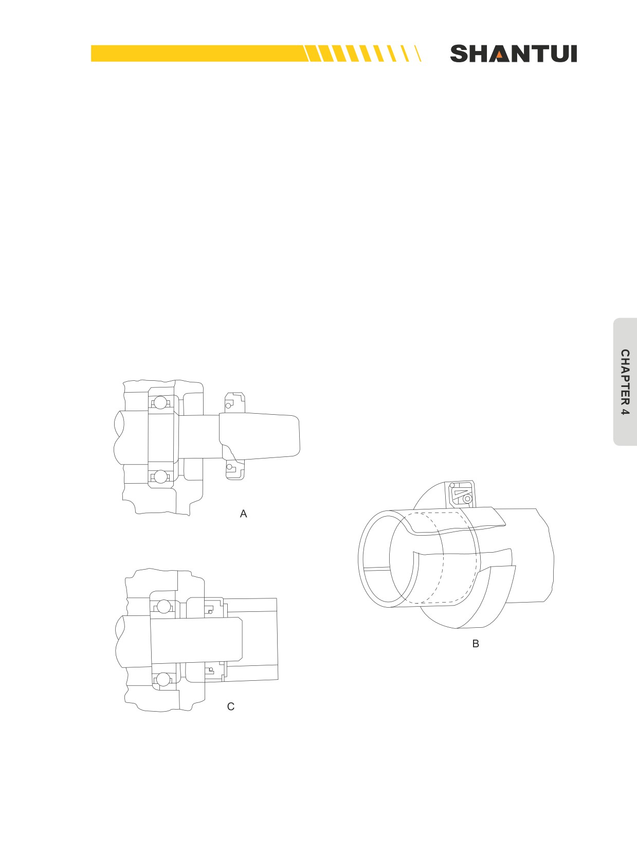
4. When installing the oil seal, you can use a conduit to let the oil seal slip into the seat (See Fig-
ure 4-75A). If you don’t have such as conduit, you can use a brass sheet to produce a makeshift
conduit (See Figure 4-75B).
5. When pressing the oil seal into the seat (See Figure 4-75C), you must use a suitable tool, to
make the pressure applied on the end surface of the oil seal even. The diameter of the tool
should be 0.5-1mm smaller than the seat hole, and its free end should have a shape suitable for
being hammered.
Figure 4-75: Oil seal installation of the A, B and C
217

ADDITIONAL TABLE | MAINTENNANCE
4.4 ADDITIONAL TABLE: USE OF FUEL, COOLANT AND LUBRICANTS AC-
CORDING TO AMBIENT TEMPERATURE
Rated
Ambient temperature and suitable oil
usage
Locations
(liter)
-30
-20
-10
0
5
10
15
20
25
30
35
40
45°C
Engine
-10~ -30 light diesel
450
Fuel tank
SAE10W-30
Engine
45
oil pan
*SAE15W-40
SAE10W-30
Torque con-
verter
Transmis-
*SAE15W-40
122
sion case
Steering
case
SAE30
SAE10W-30
Hydraulic
110
oil tank
*SAE15W-40
SD22: 82
SAE10W-30
SD22E:
Final drive
case
82
*SAE15W-40
SD22S:
102
Track roller
0.28~0.32
Carrier
SAE85W-140
0.47~0.53
roller
Idler
0.28~0.53
The re-
maining
Suitable
No.2 and No.3 lithium-based lubricating grease
lubricating
amount
locations
Soft water + antifreeze
Engine
Coolant
79
Soft water
218
MAINTENNANCE | ADDITIONAL TABLE
Note:
1. Oil marked with “*” is the alternative to the oil in the column, and when the oil in the above line
is not available, the oil with * can be used as the alternative.
2. All the lubricant brands are the CF Class. If the CD Class is used, the oil change time should be
1/2 of the required time.
3. When ambient temperature is lower than -20°C, the oil in the engine oil pan should be changed
to SAE5W-20.
4. When adding oil, pull out the filter screen from the oil injection port first, use clean diesel to wash
it clean, and then put it back to the oil injection port before going ahead to add oil. Oil that has
been fully sedimented should be used.
5. The amount of oil or grease added should meet the requirement, not too much or too less.
6. The tools for adding oil or water must be clean, and they should be put in covered boxes or cabi-
nets after use.
7. Before draining oil, preheat the oil to 30-40°C.
SAE is the internationally accepted oil numbering system.
219