Shantui SD22. Operation and Maintenance Manual - 4
STRUCTURE & PRINCIPLE | FINAL DRIVE
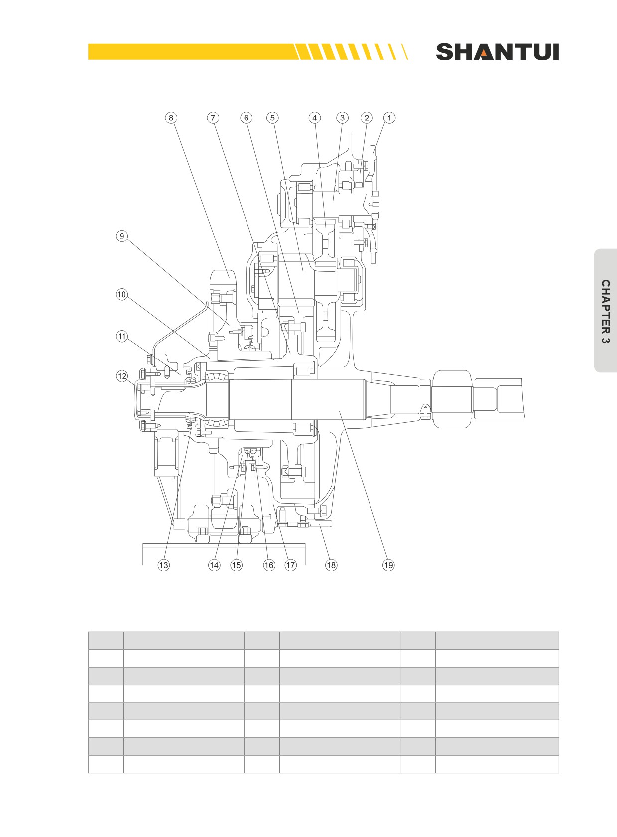
Figure3-38: The final drive’s mechanism of SD22, SD22E and SD22D
No.
Name
No.
Name
No.
Name
1
Drive disc
8
Drive sprocket
15
Floating oil seal
2
Bearing support
9
Sprocket hub
16
Oil seal cover
3
Primary driving gear
10
Driving wheel's nut
17
Casing body
4
Primary driven gear
11
Support
18
Guard plate
5
Secondary driving gear
12
Cover
19
Half shaft
6
Secondary driven gear
13
Floating oil seal
7
Hub
14
Oil seal cover
113
DRIVE SYSTEM‘S OPERATION | STRUCTURE & PRINCIPLE
3.9 DRIVE SYSTEM'S OPERATION
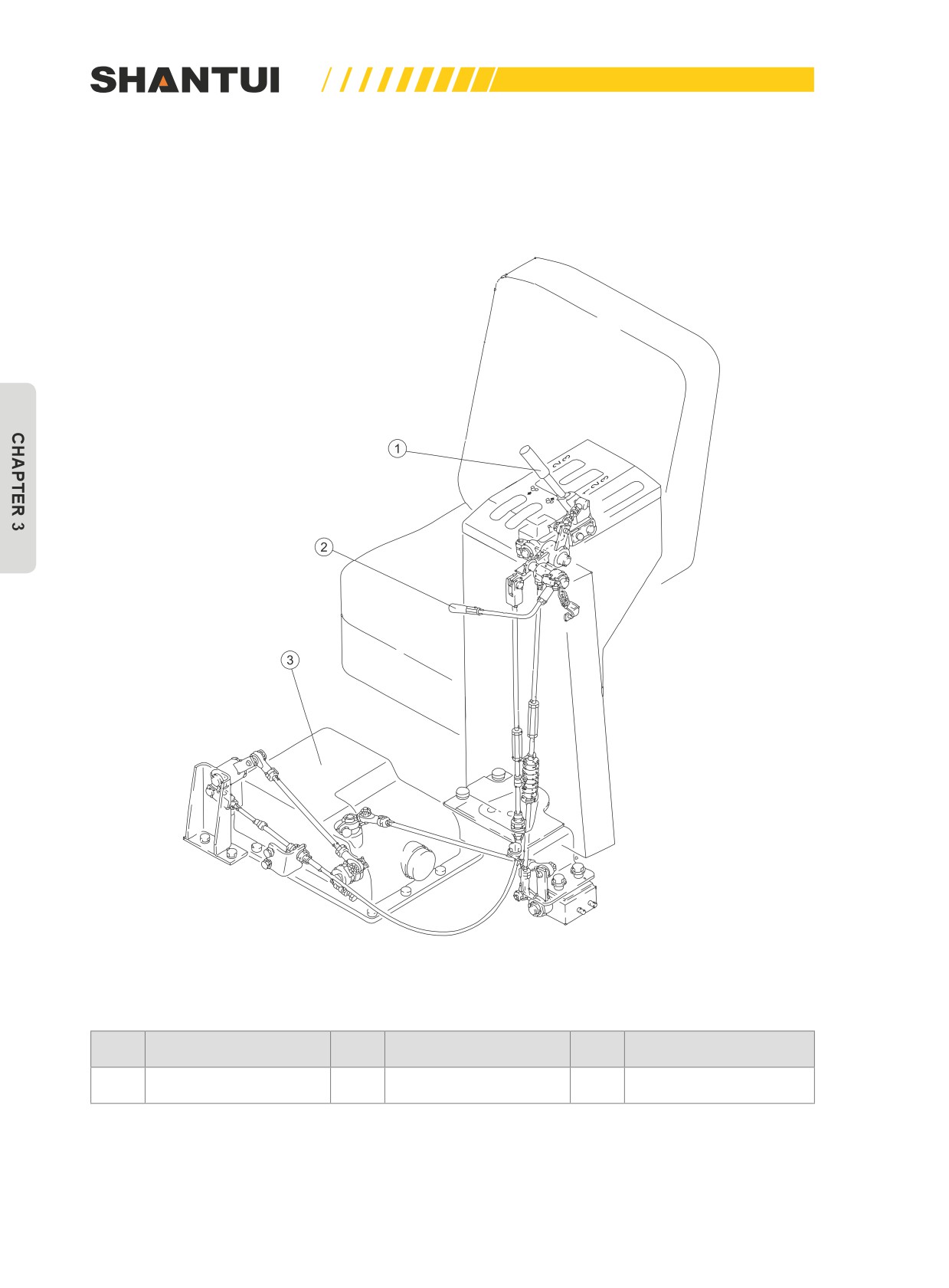
3.9.1 GEAR SHIFT (SEE FIGURE 3-39)
Figure 3-39
No.
Name
No.
Name
No.
Name
1
Gear shift lever
2
Gear shift lock lever
3
Transmission Valve
114
STRUCTURE & PRINCIPLE | DRIVE SYSTEM‘S OPERATION
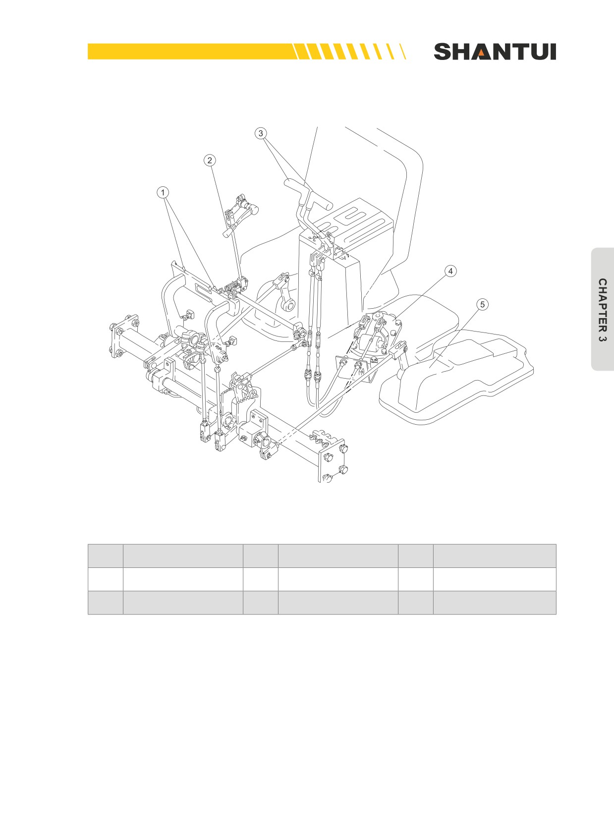
3.9.2 STEERING (SEE FIGURE 3-40)
Figure 3-40
No.
Name
No.
Name
No.
Name
1
Brake pedal
3
Steering control lever
5
Brake valve
2
Brake lock lever
4
Steering valve
115
WALKING MECHANISM | STRUCTURE & PRINCIPLE
3.10 WALKING MECHANISM
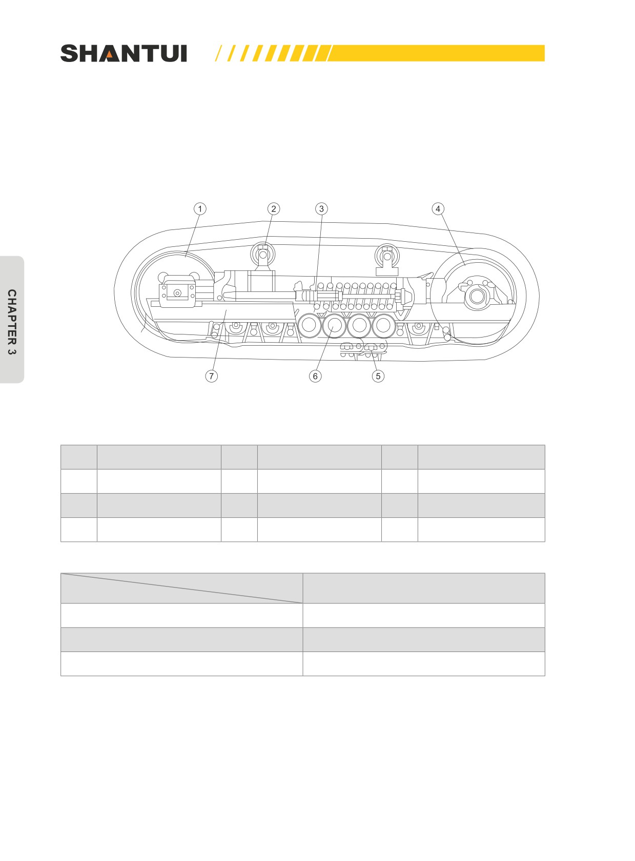
The walking mechanism (See Figure 3-41) mainly consists of the track frame (7), the driving wheel
(4), the idler (1), the track roller (6), the carrier roller (3), as well as the track and the track tension
device, to realize the walking of the bulldozer.
s
D
s s s D
s
Figure 3-41: The walking mechanism of SD22
No.
Name
No.
Name
No.
Name
1
Idler
4
Driving wheel
7
Track frame
2
Carrier roller
5
Track
3
Spring
6
Track roller
Content
Number and sequence
Model
SD22/F/C/W/H
6 (S. D. S. S. D. S)
SD22E/D
7 (S. D. S. D. S. D. S)
SD22S/R
8 (D. S. D. S. S. S. D. S)
116
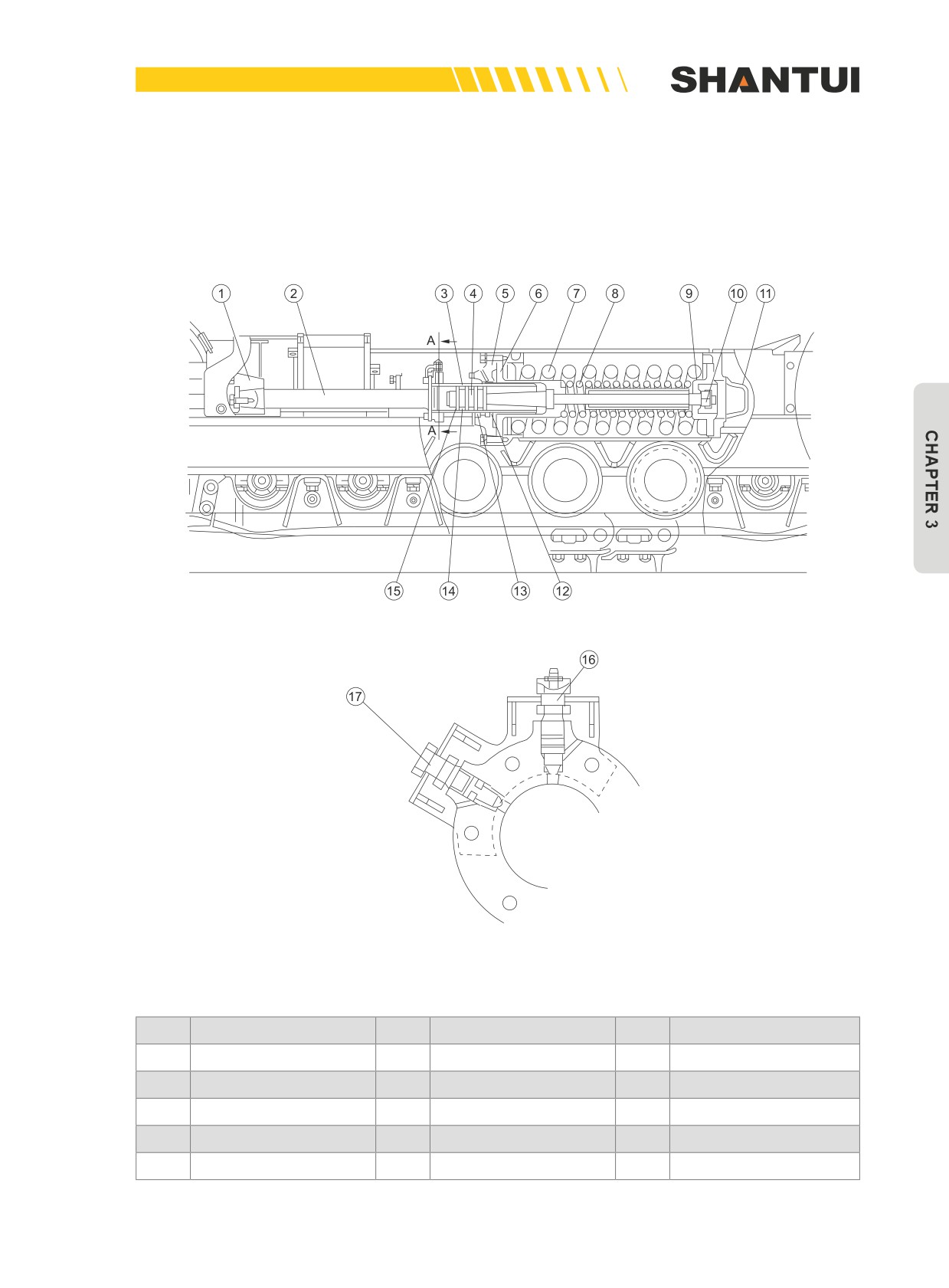
STRUCTURE & PRINCIPLE | WALKING MECHANISM
3.10.1 TRACK TENSION DEVICE (SEE FIGURE 3-42)
The role of the tension device is to ensure that the track has sufficient tension, to reduce the shock
jump of track during walking and prevent it from falling off during winding.
Figure 3-42
No.
Name
No.
Name
No.
Name
1
Seat
6
Sleeve, Guide
11
Sleeve, Guide
2
Shaft
7
Limit pipe
12
Oil plug
3
Oil cylinder
8
Spring
13
Oil injection nozzle
4
Piston
9
Lever
5
Cover
10
Tube
117
WALKING MECHANISM | STRUCTURE & PRINCIPLE
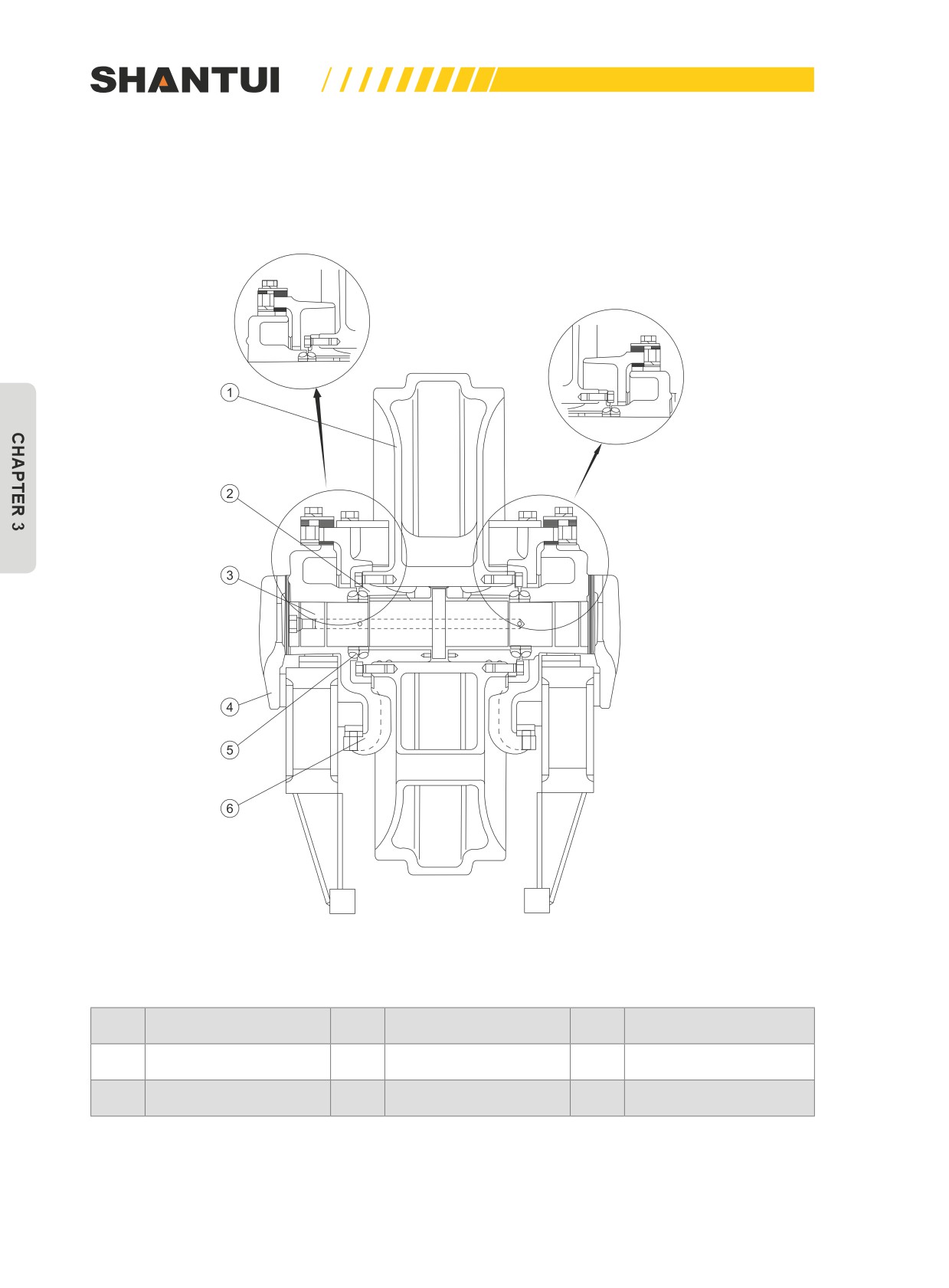
3.10.2 IDLER (SEE FIGURE 3-43)
The idler is mainly to guide the track link and track.
Figure 3-43
No.
Name
No.
Name
No.
Name
1
Idler
3
Idler axle
5
Floating seal ring
2
Sleeve
4
Side plate
6
Guider
118
STRUCTURE & PRINCIPLE | WALKING MECHANISM
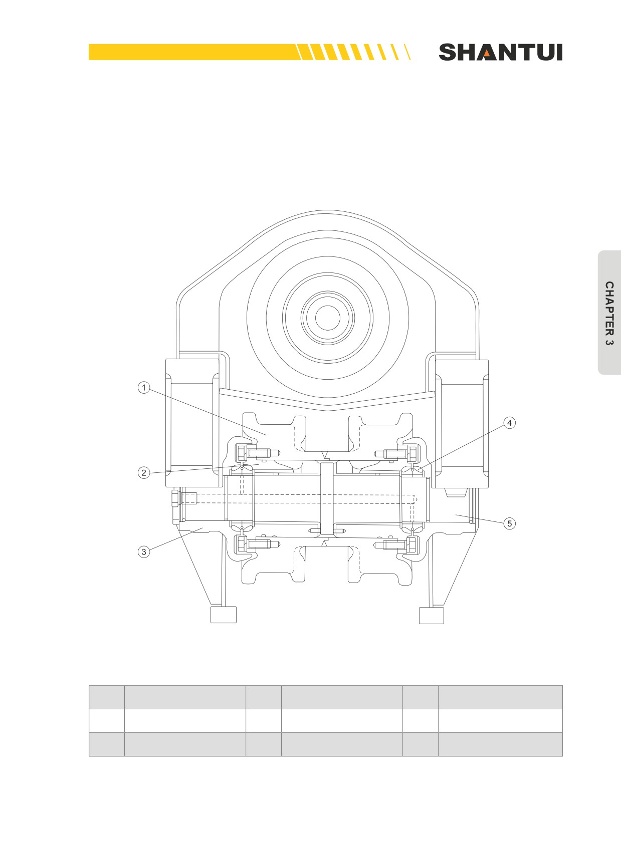
3.10.3 TRACK ROLLER (SEE FIGURE 3-44)
It supports the weight of the bulldozer, to prevent the lateral derail of the track. Track roller can have
a single flange and double flange structure. This figure shows a double flange track roller’s structure.
Except for the shape of the track roller’s hub (1), other structures of the single-flange track roller and
the double-flange track roller are the same.
Figure 3-44
No.
Name
No.
Name
No.
Name
1
Track roller hub
3
Cover
5
Shaft
2
Bushing
4
Floating oil seal
119
WALKING MECHANISM | STRUCTURE & PRINCIPLE
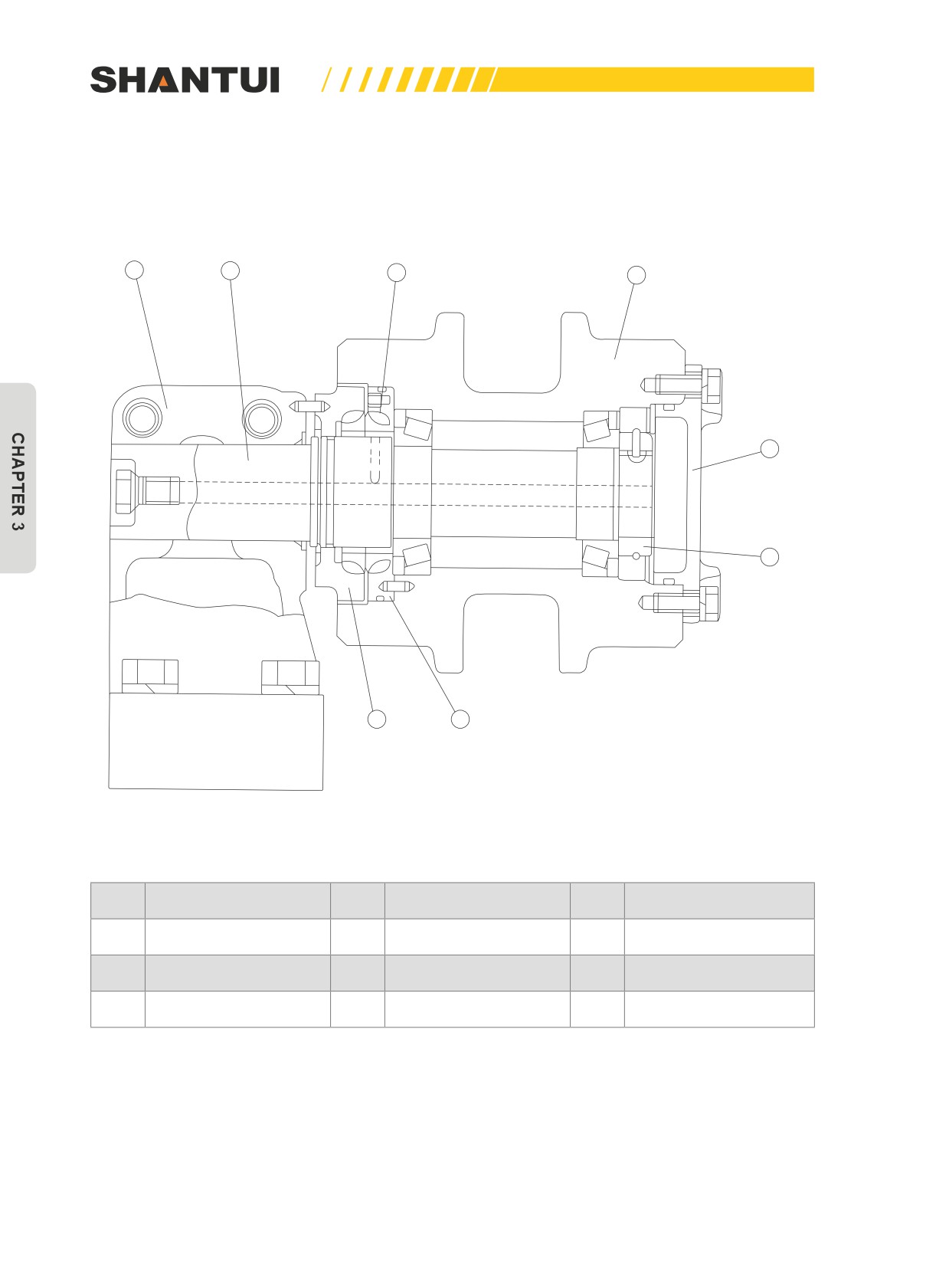
3.10.4 CARRIER ROLLER (SEE FIGURE 3-45)
It supports the upper track, to prevent the track from dropping too much, and to reduce the track’s
shock-jump during moving as well as void the track from fall slipping off sideways.
1
2
3
4
5
6
8
7
Figure 3-45
No.
Name
No.
Name
No.
Name
1
Bracket
4
Carrier roller
7
Floating seal seat
2
Shaft
5
Cover
8
Floating seal seat
3
Floating oil seal
6
Nut
120
STRUCTURE & PRINCIPLE | WALKING MECHANISM
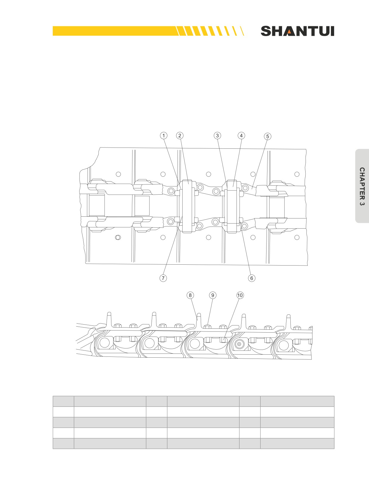
3.10.5 TRACK
Track’s role is to support the bulldozer’s weight, to ensure the bulldozer’s traction, to enable it to
have sufficient driving force.
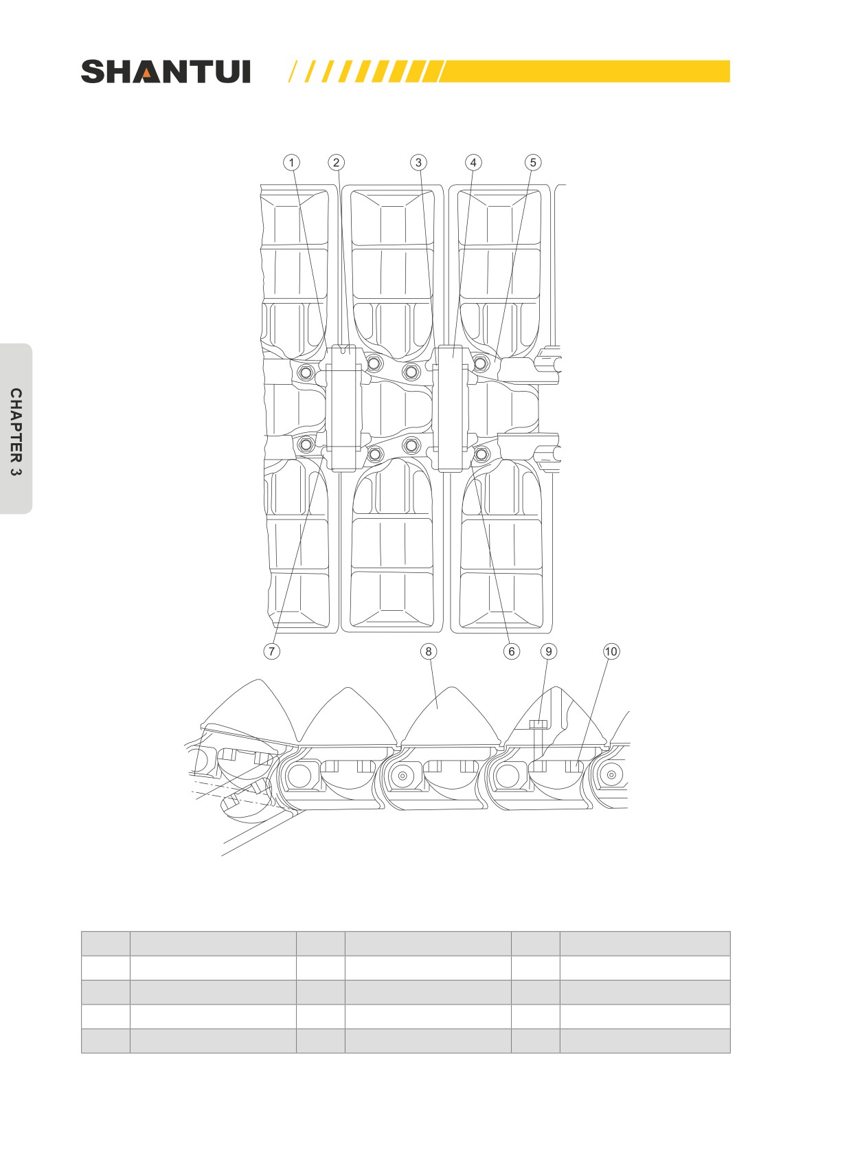
Figure 3-46 is the track assembly of bulldozers SD22, SD22E, and SD22D. Figure 3-47 is the track
assembly of bulldozer SD22S.
Figure 3-46
No.
Name
No.
Name
No.
Name
1
Ring, Dust
5
Track link
9
Track bolt
2
Fixed pin
6
Spindle sleeve
10
Track Nut
3
Seal ring
7
Sleeve
4
Master pin
8
Track shoe
121
WALKING MECHANISM | STRUCTURE & PRINCIPLE
Figure 3-47
No.
Name
No.
Name
No.
Name
1
Ring, Dust
5
Track link
9
Track bolt
2
Fixed pin
6
Spindle sleeve
10
Track Nut
3
Seal ring
7
Sleeve
4
Master pin
8
Track shoe
122
STRUCTURE & PRINCIPLE | WALKING MECHANISM
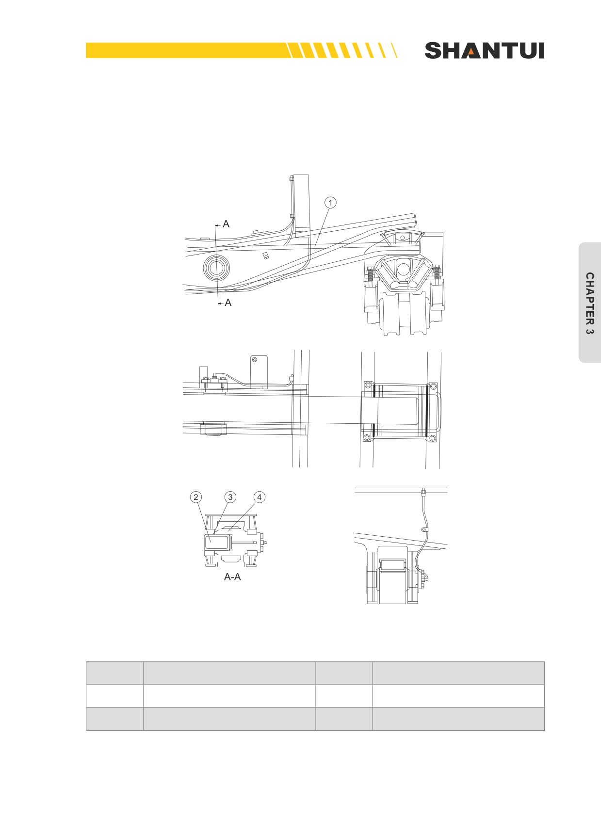
3.10.6 EQUALIZER BAR (SEE FIGURE 3-48)
It connects the frame and the walking system, to play a buffering role; at the same time, when the
ground is not even, it can ensure that the track frame can swing up and down.
Figure 3-48
No.
Name
No.
Name
1
Equalizer Bar
2
Shaft
3
Sleeve
4
Sleeve
123
HYDRAULIC SYSTEM | STRUCTURE & PRINCIPLE
3.11 HYDRAULIC SYSTEM
Hydraulic system consists two parts: the work equipment’s hydraulic system and the gearshift steer-
ing hydraulic system.
3.11.1 WORK EQUIPMENT’S HYDRAULIC SYSTEM
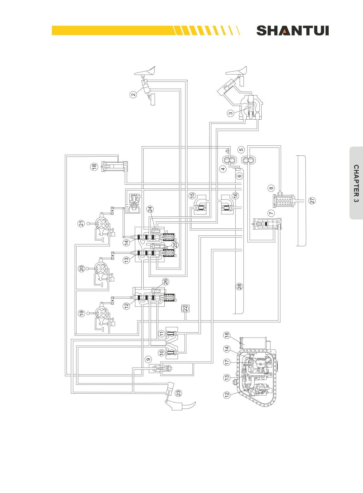
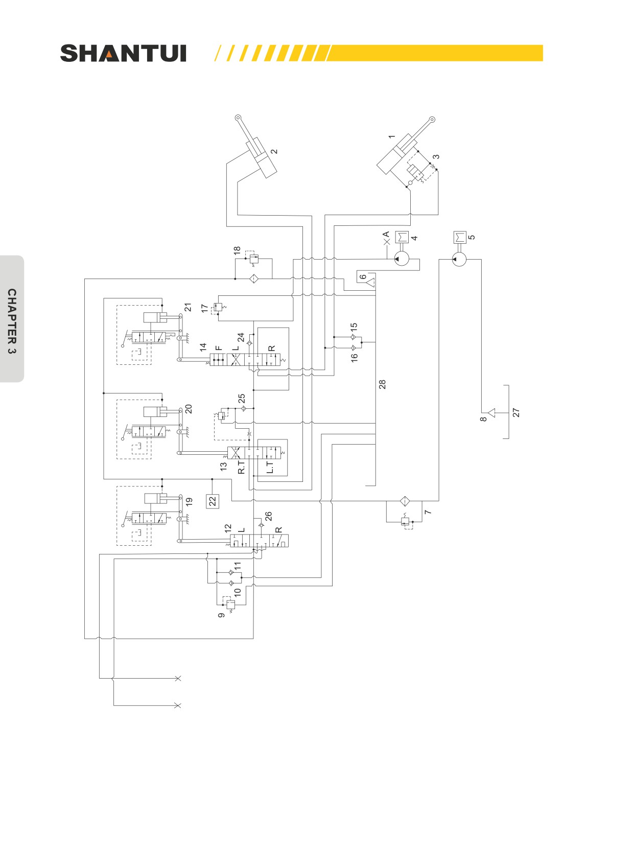
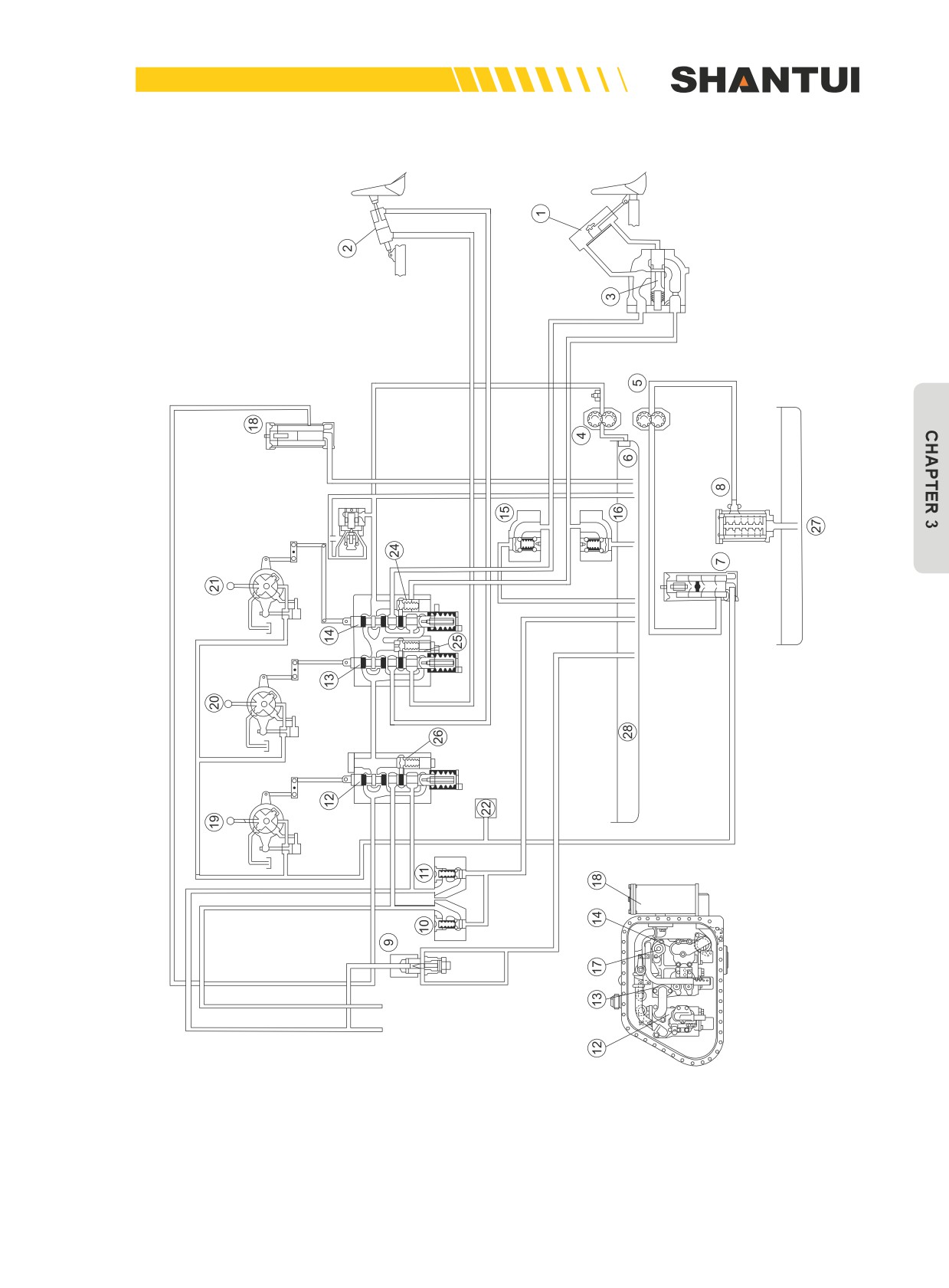
Figures 3-49 through 3-52 are the schematics showing the hydraulic principle and structure of bull-
dozers SD22, SD22E, SD22D, and SD22S.
Figures 3-49: Illustration of the hydraulic principle of the bulldozers
(SD22, SD22E and SD22D)
124
STRUCTURE & PRINCIPLE | HYDRAULIC SYSTEM
Figure 3-50 is the schematic of the hydraulic system of bulldozers SD22, SD22E, and SD22D
125
HYDRAULIC SYSTEM | STRUCTURE & PRINCIPLE
Figures 3-51: Illustration of the hydraulic principle of the bulldozer
(SD22S)
126
STRUCTURE & PRINCIPLE | HYDRAULIC SYSTEM
Figure 3-52 is the schematic of the hydraulic system of bulldozers SD22S
127

HYDRAULIC SYSTEM | STRUCTURE & PRINCIPLE
No.
Name
No.
Name
1
Hydraulic oil tank
12
Blade lift valve
2
Hydraulic pump (SAL080+036)
13
Shuttle Valve
Oil-replenishing valve (blade-raising
3
Main overflow valve
14
end)
Oil-replenishing valve (blade-lowering
4
Check valve
15
end)
5
Ripper lift valve
16
Quick drop valve
Oil-replenishing safety valve (ripper-
6
17
BLADE LIFT CYLINDER
lowering end)
Oil-replenishing valve (ripper-raising
7
18
Main overflow valve
end)
8
RIPPER LIFT CYLINDER
19
Check valve
9
Check valve
20
Blade tilt valve
10
Flow control valve
21
Blade tilt cylinder
11
Check valve
22
Hydraulic oil filter
128
STRUCTURE & PRINCIPLE | HYDRAULIC SYSTEM
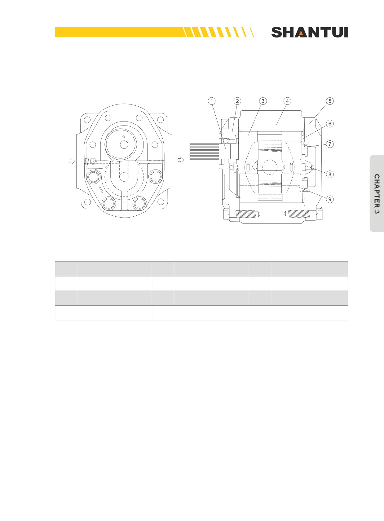
GEAR OIL PUMP (SEE FIGURE 3-53)
Gear oil pump is driven by the transfer case’s gear, to convert mechanical energy into pressure en-
ergy.
Figure 3-53
No.
Name
No.
Name
No.
Name
1
Driving gear
4
Body, Pump
7
Ring
2
Front pump cover
5
Rear pump cover
8
Seal ring
3
Bushing
6
Sealing film
9
Driven gear
129
HYDRAULIC SYSTEM | STRUCTURE & PRINCIPLE
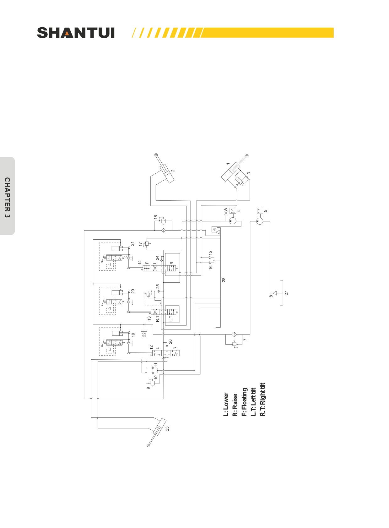
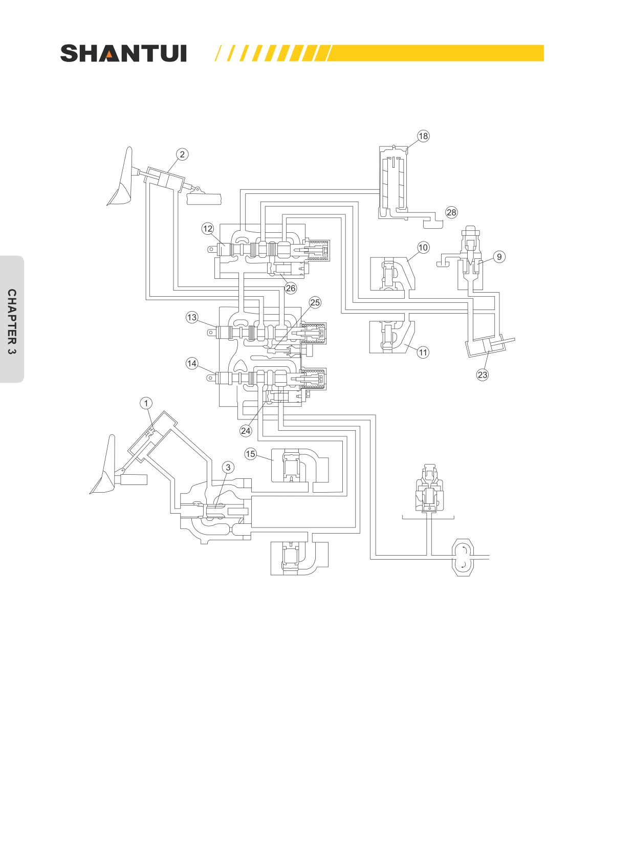
Work equipment’s hydraulic operating principles (See Figure 3-54)
Figure 3-54
The gear pump sucks out the operating oil from the hydraulic tank (28), and pumps it into the
change valve (12), (13), (14). If various work equipment is not operated, the oil will return to the
hydraulic tank through the change valve (28) and the oil filter (18). If the oil filter is blocked at this
point, the oil will push open the oil filter’s safety valve to return to the hydraulic tank. If you oper-
ate change valves (14) or (13), you can control the blade’s cylinder to raise, lower, keep or float the
blade, as well as control the tilting cylinder to tilt the blade to the left or to the right or to keep the
blade unmoved. Operating the change valve (12) can control the ripper oil cylinder, to realize the rip-
per’s raising, lowering and keeping.
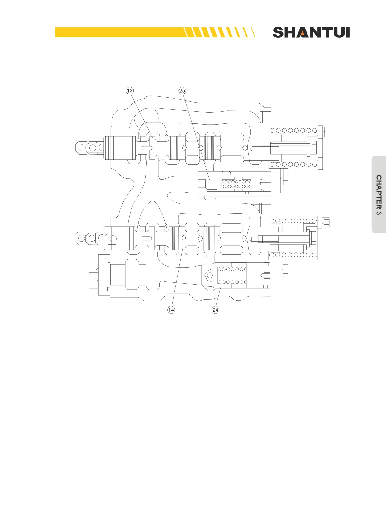
There is an intake check valve (24), (25), (26) before change valve to overcome the possible “nodding
impact” from the circular movement of various working mechanisms.
130
STRUCTURE & PRINCIPLE | HYDRAULIC SYSTEM
In order to let the tilt cylinder have an ideal movement speed, we have provided the flow con-
trol valve (25). (See Figure 3-55)
Figure 3-55
131
HYDRAULIC SYSTEM | STRUCTURE & PRINCIPLE
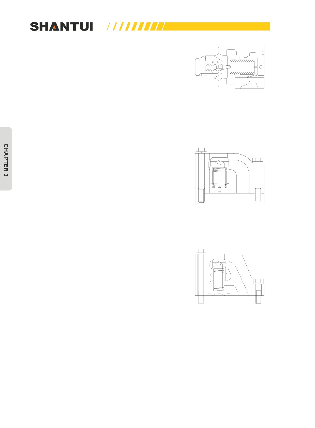
The overload valve (9) is provided in order to avoid that the
system pressure from becoming too high due to the exessive
load during the ripping operation.
During operation, if the load is too high, system pressure will
exceed the set pressure of 14Mpa for a short time. In this
case, the main overflow valve (17) is opened, and the operat-
ing oil returns to the oil tank through the overflow valve, to pro-
Figure 3-56
tect the system . The main overflow valve’s structure is shown
in Figure 3-56.
When the external force’s direction is the same as the oil cylin-
der piston’s moving direction, in order to avoid a vacuum from
occurring within the oil cylinder, the oil-replenishing valves (10),
(11), (15), (16) are provided (See Figure 3-52) Oil-replenishing
valve's structure shown in Figure 3-57 and Figure 3-58
Figure 3-57
Figure 3-58
132
STRUCTURE & PRINCIPLE | HYDRAULIC SYSTEM
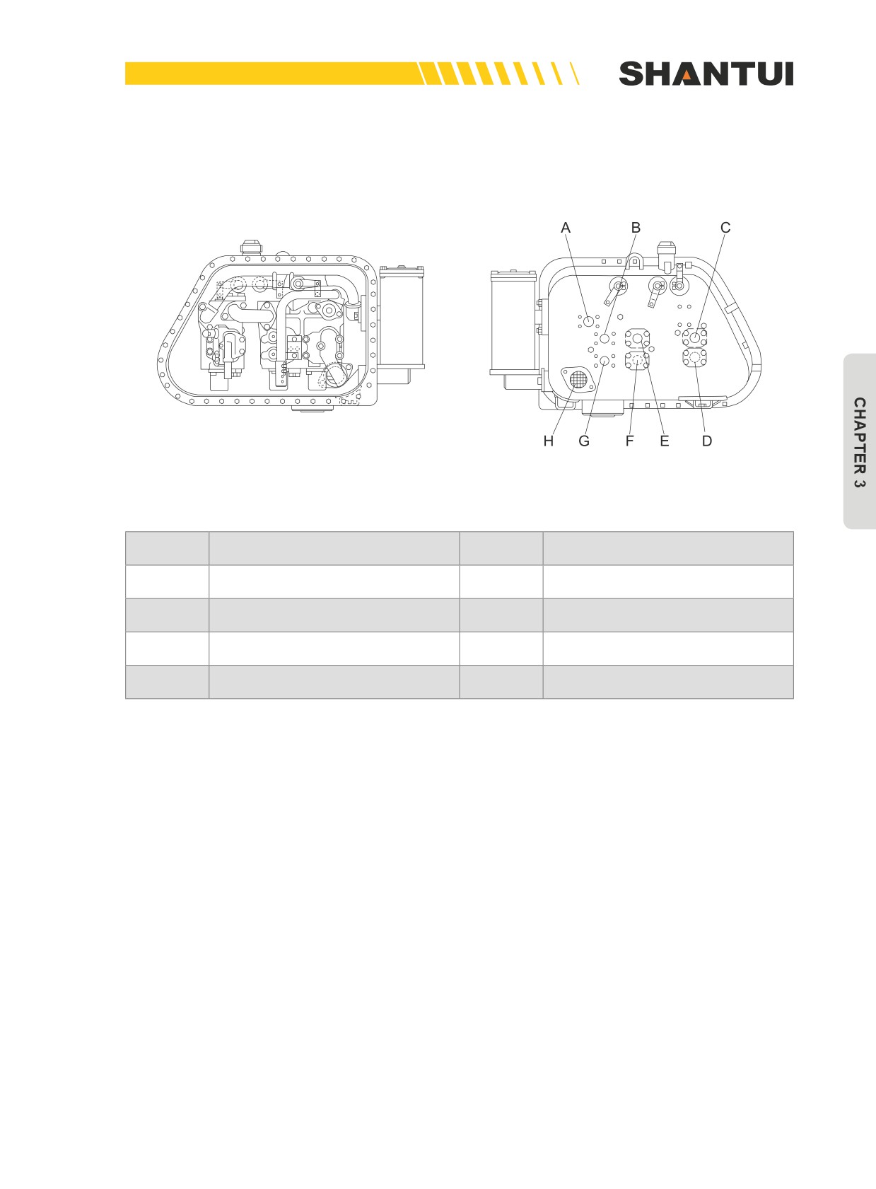
All the above valves are within the hydraulic tank.
In order to prevent dust from contaminating the operating oil, the operating oil tank is made into a
closed structure (Figure 3-59)
Figure 3-59
No.
Name
No.
Name
A
Inlet
B
To blade cylinder bottom (lower)
C
To ripper cylinder head
D
To ripper cylinder bottom
To the head of the tilting cylinder (tilt
To the bottom of the tilting cylinder
E
F
to the right)
(tilt to the left)
G
To blade cylinder head (raise)
H
The pump’s oil intake
133
HYDRAULIC SYSTEM | STRUCTURE & PRINCIPLE
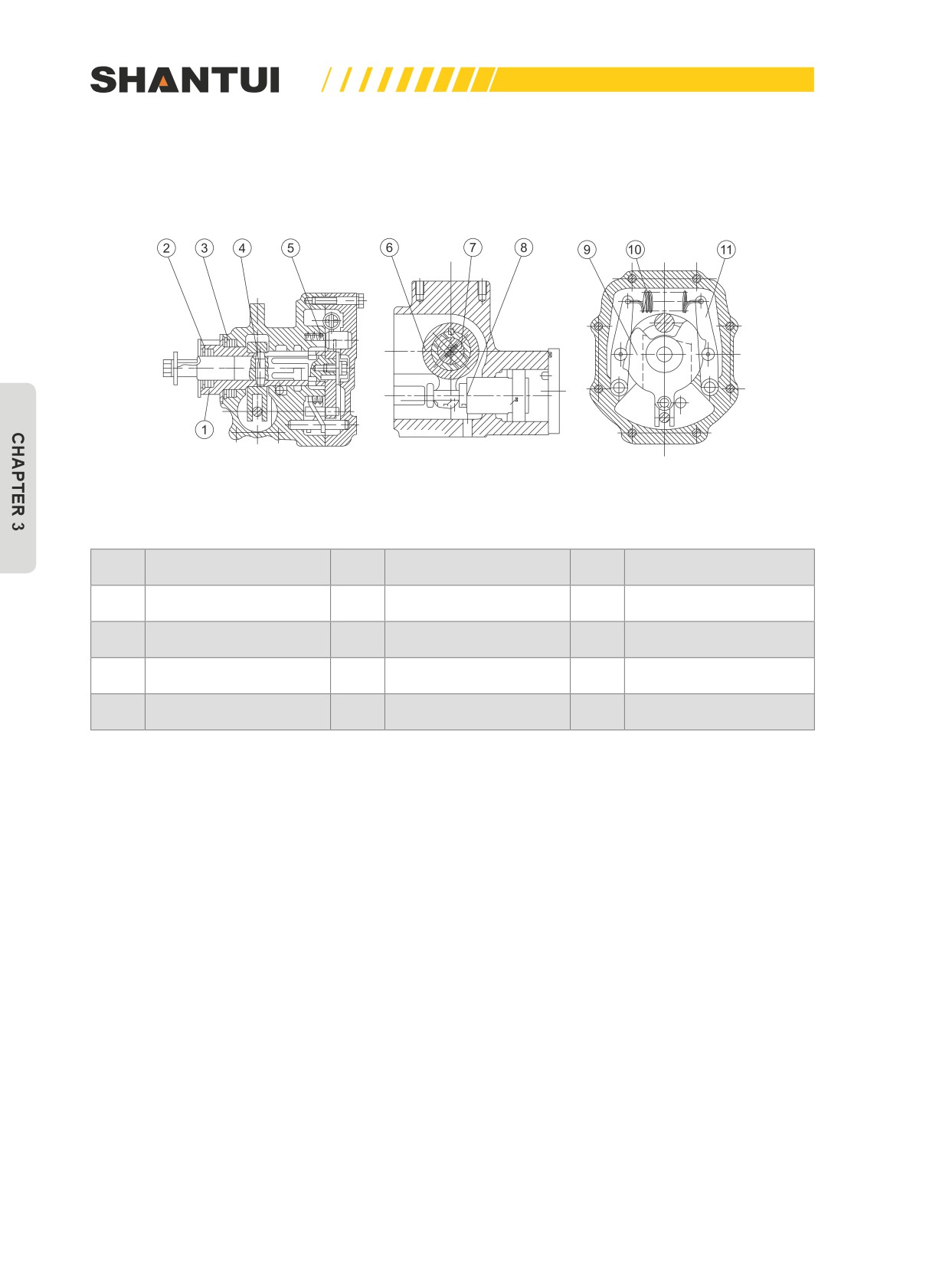
ROTARY SERVO VALVE (SEE FIGURE 3-60)
A rotation servo valve is provided in order to reduce the force needed to operation the work equip-
ment’s change valve and improve its tuning performance.
Figure 3-60
No.
Name
No.
Name
No.
Name
1
Sleeve
5
Spring
9
Detent
2
Oil seal
6
Lever
10
Spring
3
Oil seal
7
Roller
11
Lever
4
Pin
8
Piston
134
STRUCTURE & PRINCIPLE | HYDRAULIC SYSTEM
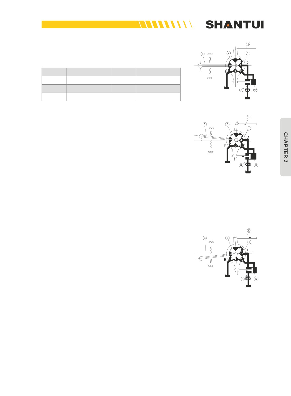
The oil of the rotation servo valve comes from the steering
pump, and the oil returns to the steering case. (See Figure
3-61)
No.
Name
No.
Name
1
Valve cover
6
Handle
7
Valve core
8
Piston
12
Oil cylinder
13
Connecting rod
Figure 3-61
The action output end of the rotation servo valve connects to
the valve stem of the work equipment’s change valve through
the connecting rod, to operate the change valve t change di-
rection. There is a positioning mechanism in the floating posi-
tion.
If lever (6) is operated to let valve core (7) rotate clockwise for
an angle (see Figure 3-62), the passage between A and C will
be opened, the pressure oil will enter the bottom of oil cylinder
(12) to push piston (8) and valve cover (1) to rotate clockwise
Figure 3-62
for an angle too, and the connecting rod (13) will operate the
change valve’s stem to move a distance. As at this point the
rotation of valve cover (1) cuts off the passage between A and
C, piston (8) will stop moving immediately. It can move con-
tinuously only when (6) continues to be operated.
If lever (6) is operated to let valve core (7) rotate clockwise
for an angle (see Figure 3-62), the passage between A and
C will be opened, the pressure oil will enter the oil cylinder to
push piston (8) and valve cover (1) to rotate clockwise for an
angle too, and the connecting rod (13) will operate the change
valve’s stem to move a distance. As at this point the rotation of
valve cover (1) cuts off the passage between A and C, piston
(8) will stop moving immediately. It can move continuously only
when (6) continues to be operated.
Figure 3-63
Figure 3-66 shows a neutral operating condition. At this point,
neither the passage between A and C nor the passage be-
tween B and C is opened, the oil cylinder’s piston does not
move, and the valve cover does not rotate either.
As the operation force to the lever just needs to overcome the
friction between valve cores (7) and (1), and the output force is
provided by the oil cylinder, the operation force is dramatically
reduced.
135
HYDRAULIC SYSTEM | STRUCTURE & PRINCIPLE
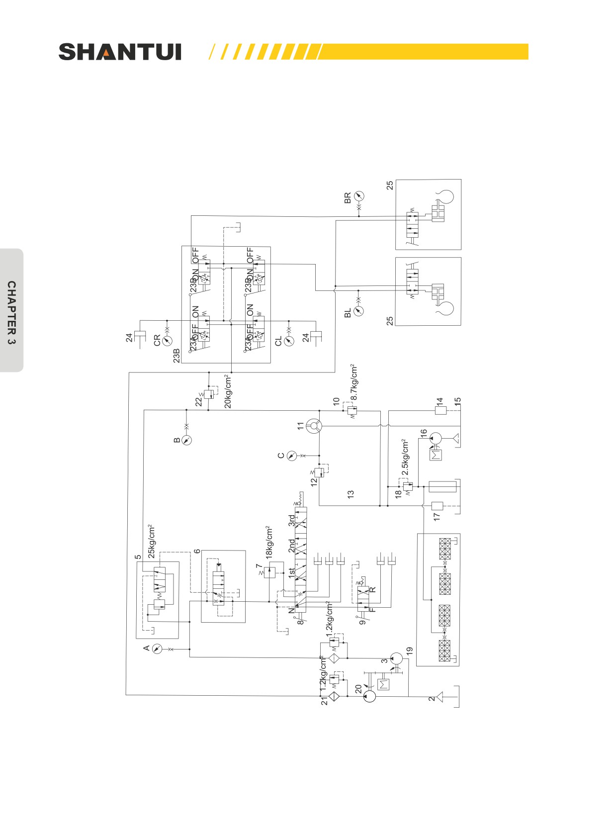
3.11.2 GEARSHIFT AND STEERING HYDRAULIC SYSTEM
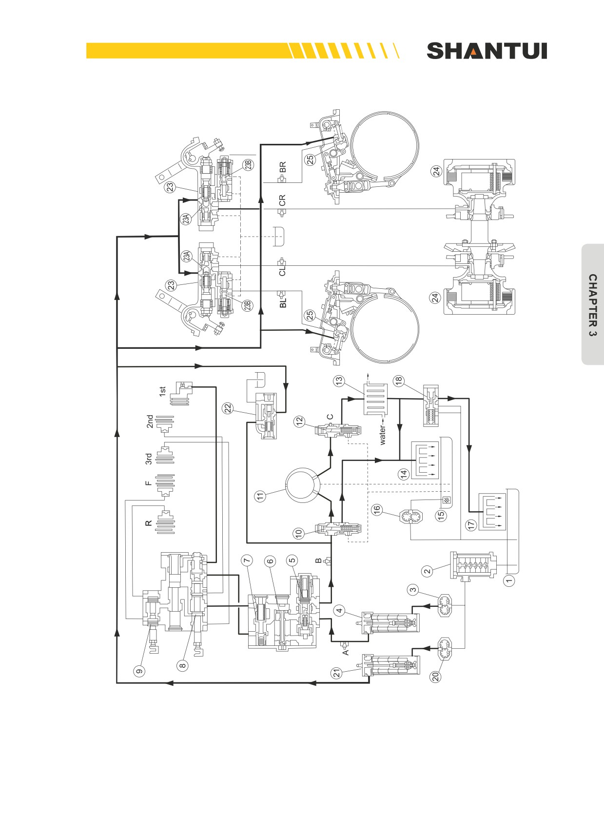
The schematic showing the principle of bulldozer’s gearshift steering hydraulic system (see Figure
3-64) and bulldozer’s structural schematic (see Figure 3-65).
Figure 3-64: The schematic showing the principle of bulldozer’s gearshift steering hydraulic system
136
STRUCTURE & PRINCIPLE | HYDRAULIC SYSTEM
Figure 3-65: The illustration of gearshift steering’s structure
137
HYDRAULIC SYSTEM | STRUCTURE & PRINCIPLE
GEARSHIT’S HYDRAULIC SYSTEM
The fifth clutch
The fourth clutch
The third clutch
The second
clutch
The first clutch
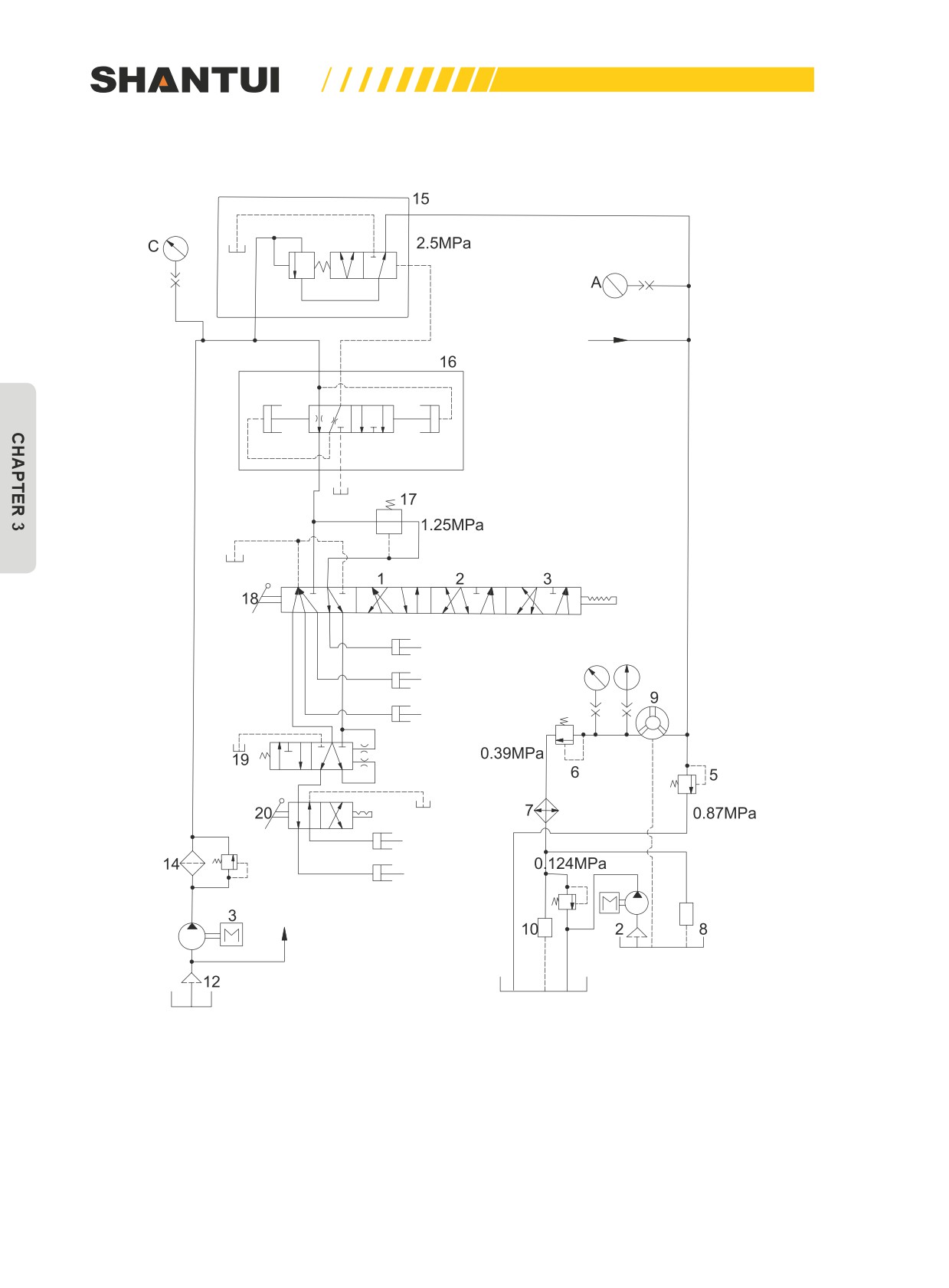
Figure 3-67: The illustration of gearshift circuit’s system principle
138
STRUCTURE & PRINCIPLE | HYDRAULIC SYSTEM
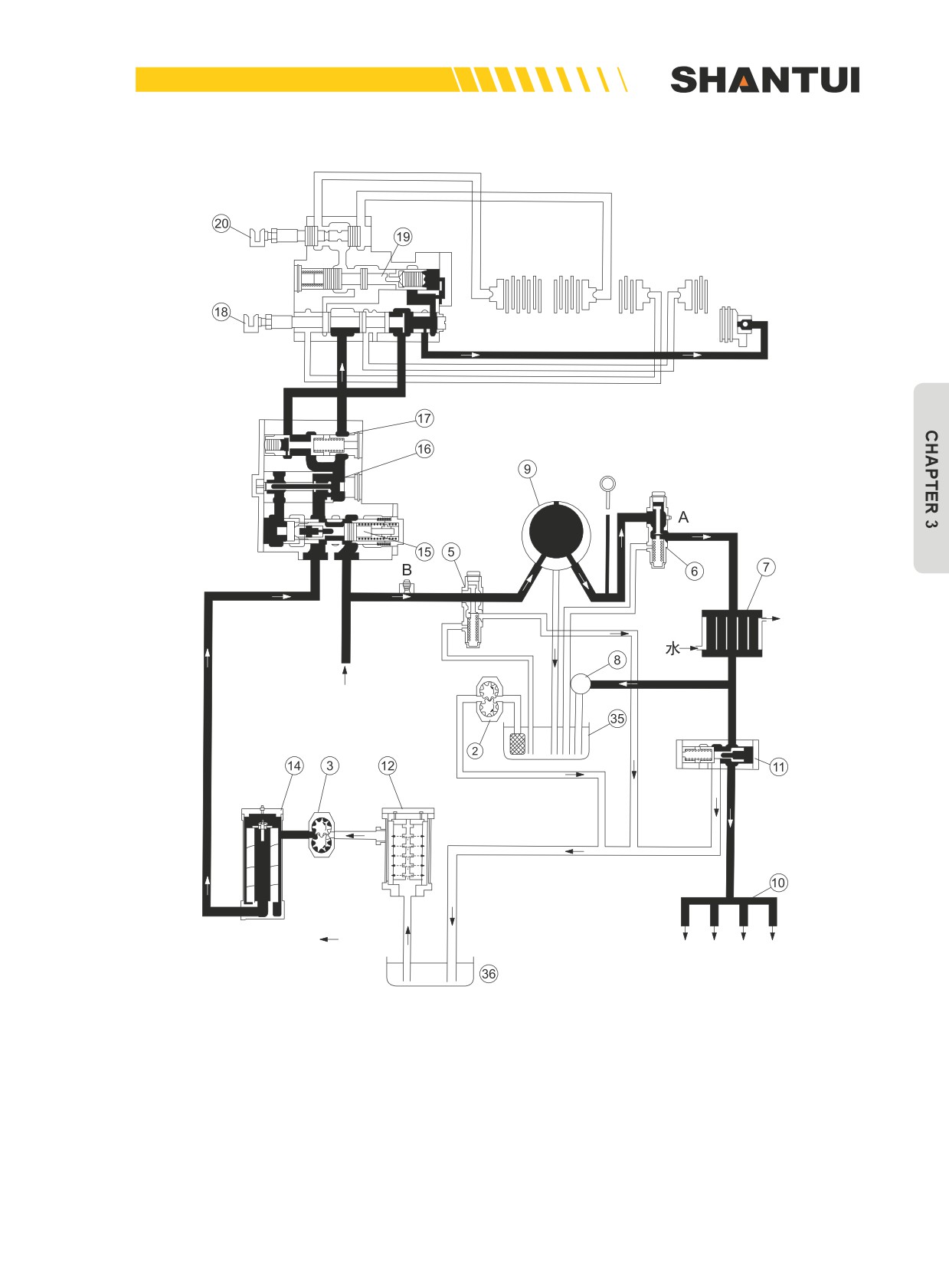
Figure 3-67: The illustration of gearshift circuit’s structure
139
HYDRAULIC SYSTEM | STRUCTURE & PRINCIPLE
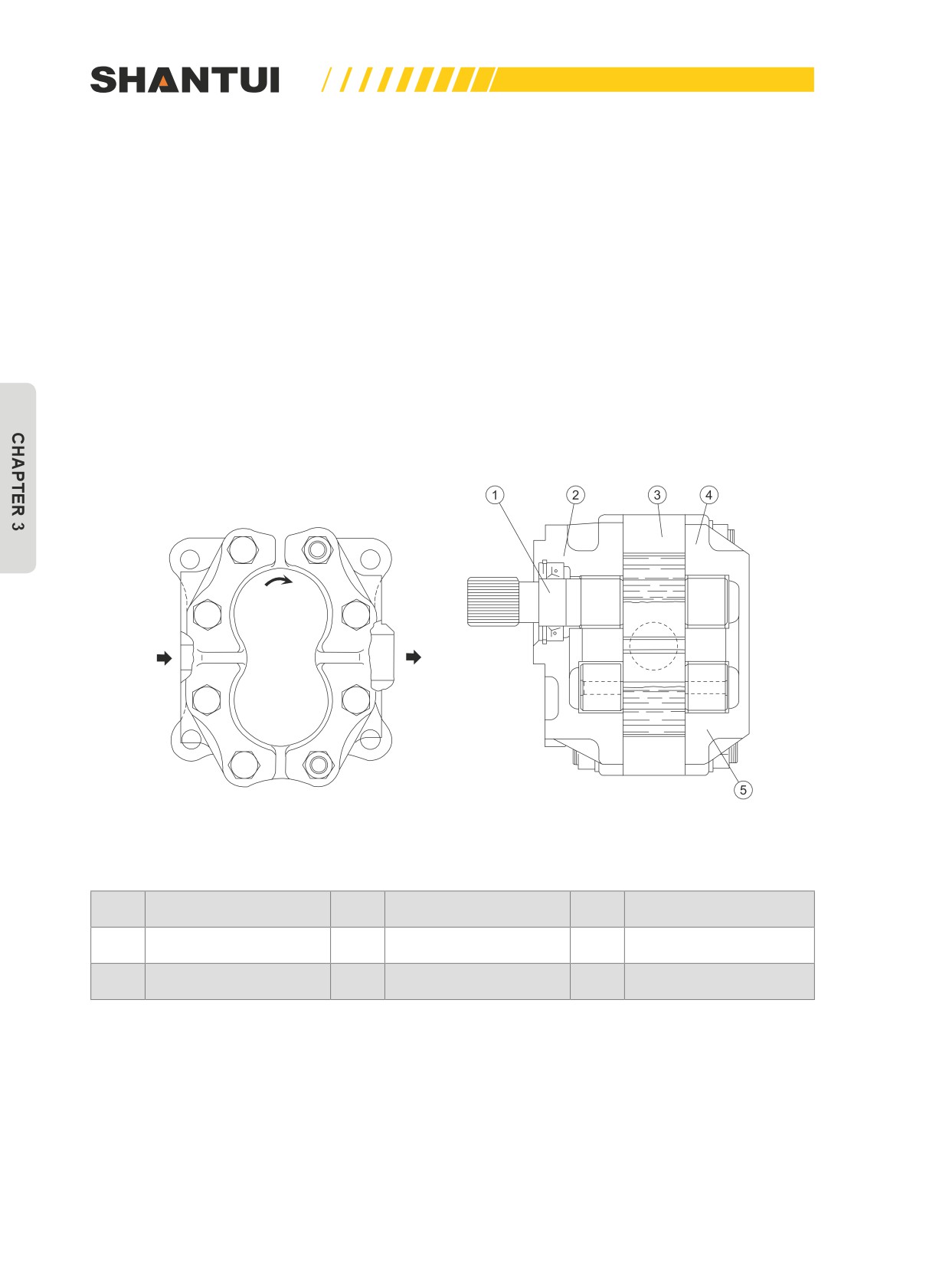
Transmission pump is a gear pump (See Figure 3-68). The transmission pump is connected with the
transfer case, to convert the mechanical energy into the hydraulic energy. The transmission pump
sucks the hydraulic oil from the steering case through the strainer (12), and the exhausted oil enters
the pressure-adjusting valve (15) through the fine filter (14). After pressure adjustment, the oil enters
the hydraulic torque converter’s overflow valve (5) (The valve's set pressure is 0.87MPa), and the
overflow oil returns to the steering case. Pressurized oil going through the overflow valve enters the
hydraulic torque converter(9), to let the hydraulic torque converter’s back pressure valve (6) ensure
that the oil in the torque converter has sufficient operating pressure. The oil going through the back
pressure valve, after being cooled by the oil cooler, returns to the lubricating valve (11), to lubricate
the transfer case due to the lubricating valve being pressed. After lubrication, the oil flows to the in-
ner of the torque converter housing; The oil overflow from the lubricating valve again goes to lubri-
cate the transmission case, and after lubrication, the oil flows into the steering case. The oil scaven-
ger pump ensures that the oil within the torque converter’s housing can continuously returns to the
steering case.
Oil inlet
Oil outlet
Figure 3-68
No.
Name
No.
Name
No.
Name
1
Driving gear
3
Body, Pump
5
Driven gear
2
Front pump cover
4
Rear pump cover
140
STRUCTURE & PRINCIPLE | HYDRAULIC SYSTEM
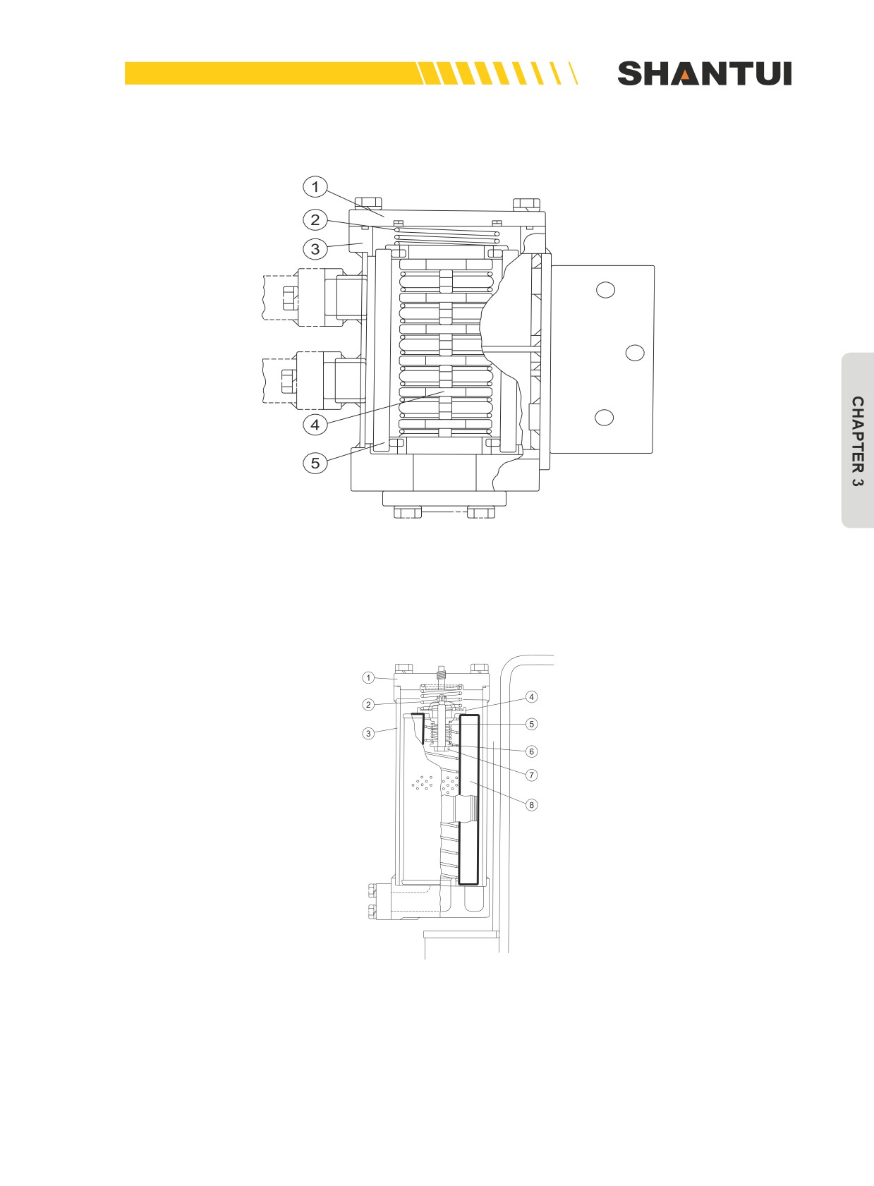
Coarse stainer's structure (see figure 3-69)
Figure 3-69
Fine filter's structure (see figure 3-70)
Figure 3-70
141
HYDRAULIC SYSTEM | STRUCTURE & PRINCIPLE
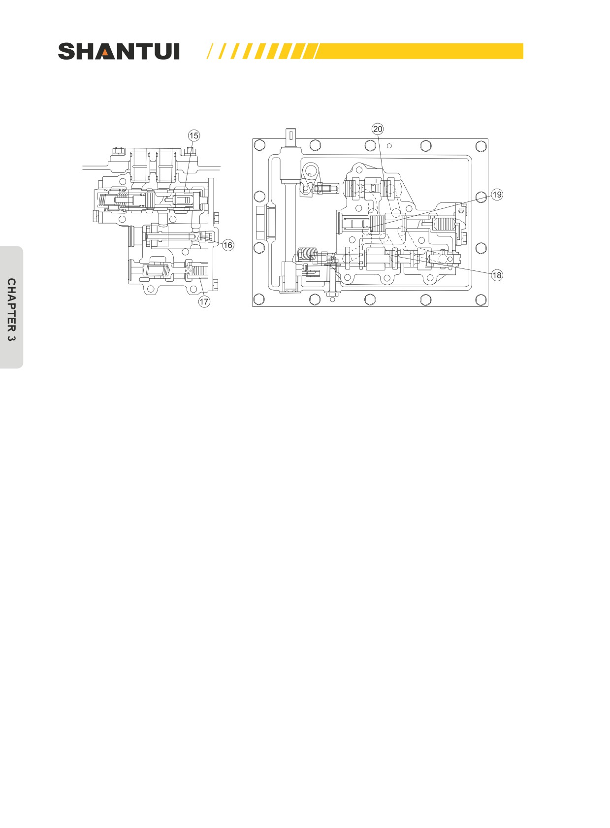
Install a control valve on the transmission case (See Figure 3-71)
Figure 3-71
Valve (15) is the pressure-adjusting valve, and the adjusting pressure is 2.5Mpa, to ensure the en-
gagement of all the clutches except for Gear 1. After reaching this pressure, the pressure-adjusting
valve is opened, to supply oil to the torque converter. Valve (16) is the fast return valve. The joint ac-
tion of this valve and the pressure-adjusting valve (15) can ensure that when the transmission case’s
various clutches are activated, they can be smoothly engaged or thoroughly disengaged.
When the transmission case’s control lever is operated, the system’s pressure changes according
to the curve in Figure 3-72. At the moment the transmission case is operated to shift a gear, the
pressure drops suddenly, to have the clutch be thoroughly separated. And then, the pressure slowly
rises, to let the clutch smoothly engage, to avoid shock, and to help increase the service life of the
drive system.
142
STRUCTURE & PRINCIPLE | HYDRAULIC SYSTEM
Valve (17) is the pressure relief valve, provided specifically for the Gear 1clutch, and the pressure at
its exit is 1.25MPa. (i.e. the engagement pressure of the Gear 1 clutch)
Valve (18) is the starting safety valve. It is provided in order to avoid the unexpected accidents when
the engine is started while the gearshift knob is on a gear (Gear I, II, III) to let the vehicle move sud-
denly. the vehicle will only start to move when the gearshift knob is in the NEUTRAL position, and
then is put on a gear.
Valve (19) is the speed valve. It is used to operate the transmission case’s clutches to get different
forward and reverse speeds.
Valve (20) is the direction valve. It is used to operate the transmission case’s first clutch and second
clutch , to let the bulldozer move forward or backward. Valves (15) through (20) return oil into the
steering case.
Pressure
rising time
Gear shift
Engagement
Time
Figure 3-72
143
WORK EQUIPMENT | STRUCTURE & PRINCIPLE
3.12 WORK EQUIPMENT
The work equipment mainly refers to the blade and the ripper, used to perform various operations
of the bulldozer. Bulldozer SD22S only has the straight tilt blade. Bulldozers SD22, SD22E, and
SD22D have three types of blades: straight tilt blade, angle blade, and U-Blade.
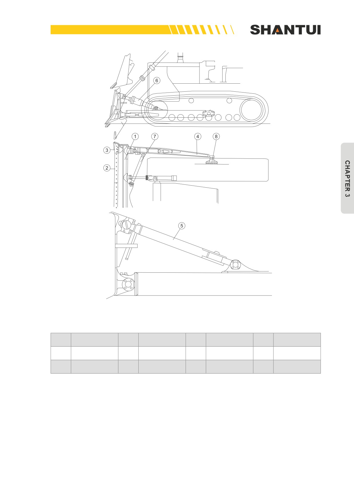
3.12.1 STRAIGHT TILT BLADE
The push rod of the straight tilt blade is a box-shaped structure, with a good anti-bending strength, a
good anti-pressure stability and good rigidity. The front end is hinged together with the blade using a
cross connector, and the back end is hinged together with the seat (8) fixed on the track frame.
Under the action of the blade’s oil cylinder, both the push rod and the blade’s head rotate with the
seat (8) as the axle, to realize the blade’s raising and lowering. Changing the length of adjusting
screw (5) can change the cutting angle of the blade. Tilting the oil cylinder (6) can enable the blade
to tilt to left or right in a direction perpendicular to the ground.
After being used for a period of time, the cutting edge (2) can be turned around and used again.
3.12.2 U-BLADE
The structure of the U-Blade is slightly the same as that of the straight tilt blade, the action principle
is completely the same, and the only difference is in the shape of the blade. No detailed description
will be made here.
144
STRUCTURE & PRINCIPLE | WORK EQUIPMENT
Figure 3-73
No.
Name
No.
Name
No.
Name
No.
Name
1
Dozer blade
2
Edge, Cutting
3
End bit
4
Push rod
Adjusting
5
6
Tilt oil cylinder
7
Arm
8
Seat
screw
145
WORK EQUIPMENT | STRUCTURE & PRINCIPLE
3.12.3 ANGLE BLADE
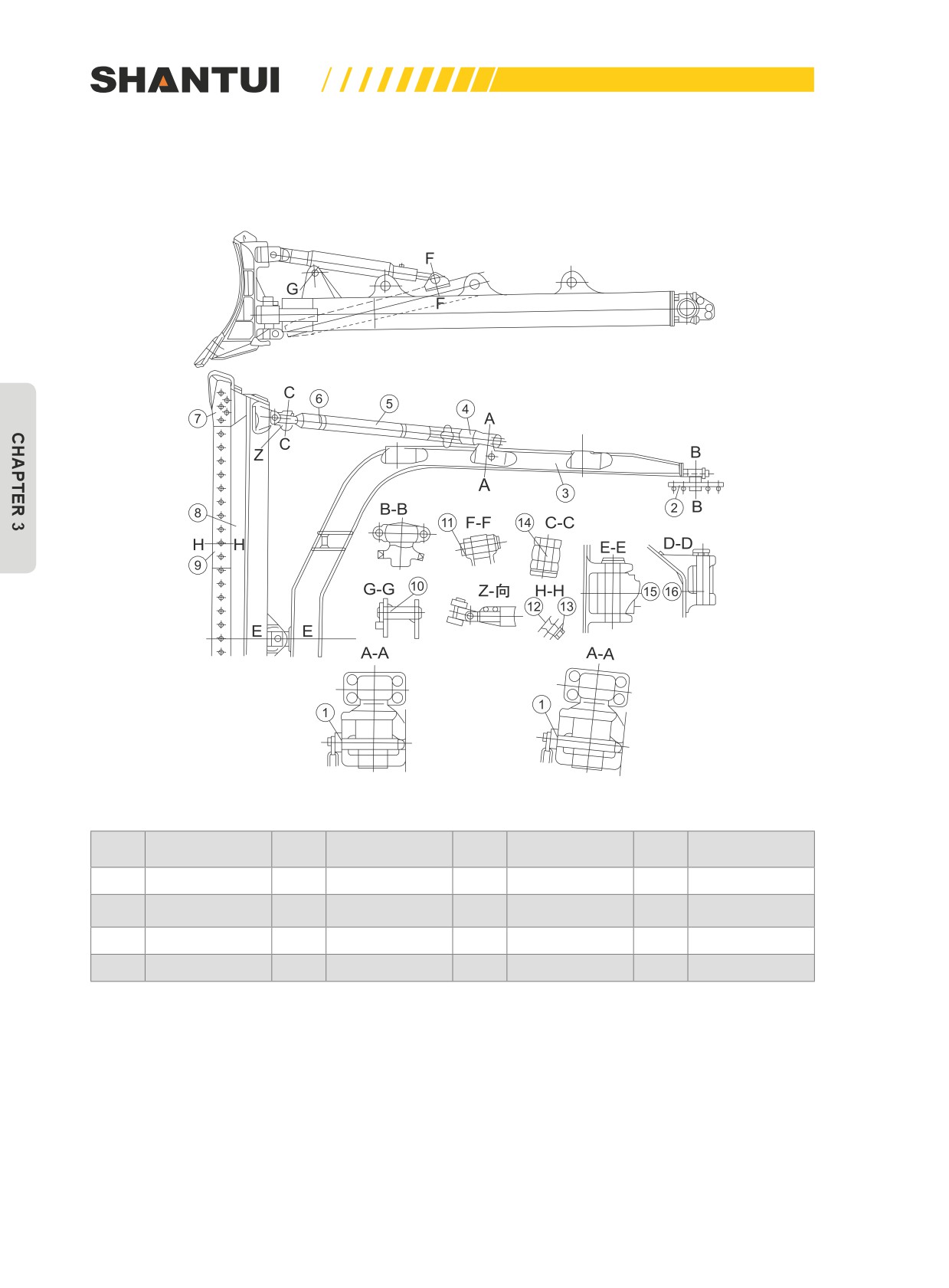
Angle blade’s structure is shown in Figure 3-74.
Figure 3-74
No.
Name
No.
Name
No.
Name
No.
Name
1
Pin
2
Seat
3
C-Frame
4
Lower support
The blade’s
5
Upper support
6
Screw
7
End bit
8
head
9
Edge, Cutting
10
Pin
11
Pin
12
Bolt
13
Nut
14
Pin
15
Pin
16
Pin
The blade (8) is hinged together with the C-Frame (3) through the upper support (5) and the lower
support (4). The C-Frame (3) is hinged together with the seat (2), which is fixed on the track frame.
The blade’s cylinder lets the C-Frame (including the blade) make the fixed-axis swing with seat (2)
as the axis.
Installing the lower support (4) on the C-Frame’s different seats through the unplug pin (1) can let
the blade have three different work positions, to realize 25° rotation to the left or right.
146
STRUCTURE & PRINCIPLE | WORK EQUIPMENT
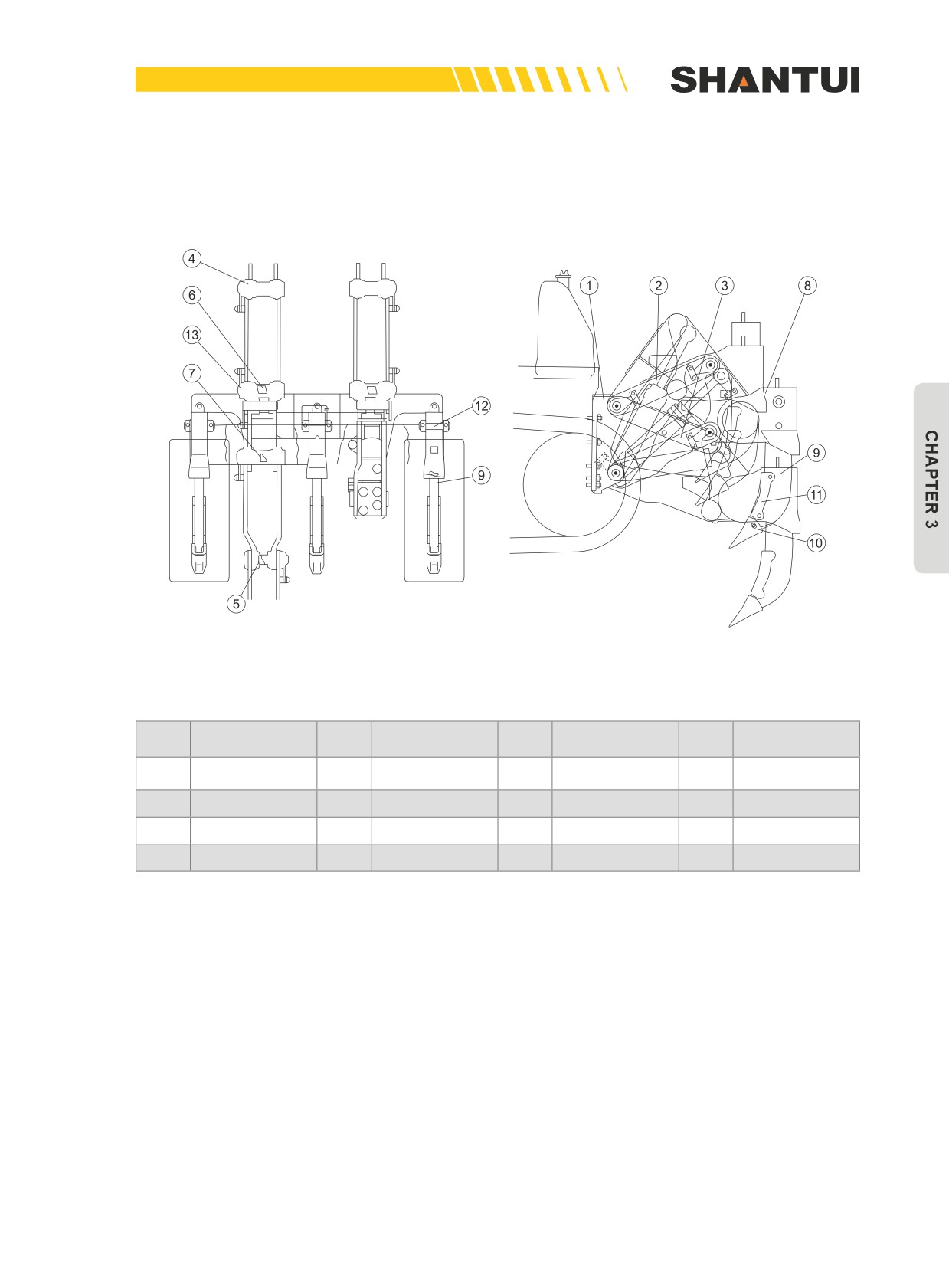
3.12.4 RIPPER (SEE FIGURE 3-75)
The ripper can be used in conjunction with the straight tilt blade and the angle blade.
Figure 3-75: Angle blade
No.
Name
No.
Name
No.
Name
No.
Name
Connecting
1
Bracket
2
Connecting rod
3
4
Pin
frame
5
Pin
6
Pin
7
Pin
8
Cross beam
9
Tooth
10
Tooth tip
11
Guard plate
12
Pin
13
Pin
The ripper is a mechanism with four connecting rods installed behind the frame. The bracket (1),
the connecting rod (2), the connecting frame (3) and the cross beam (8) are all connected through a
hinge, and the four hinging points are the four apexes of a parallelogram. So, no matter how the rip-
per’s cylinder moves, when the tooth tip cuts soil, the best cutting angle can be ensured.
The cross beam (8) has two sets of holes to provide two installation locations. After being used for a
while, the tooth tip (10) can be turned 180° to be installed again, to extend its service life. For hard
soil, you can operate using one tooth in the middle or two teeth on the two ends.
147
ELECTRIC SYSTEM | STRUCTURE & PRINCIPLE
3.13 ELECTRIC SYSTEM
3.13.1 DESCRIPTION OF THE ELECTRIC SYSTEM
The bulldozer’s electric system is mainly used to start the diesel engine, the lamps. It consists of the
starting motor, the silicon rectified generator, the magnetic switch, the voltage stabilizer and two 12V
batteries.
Notes:
1. The advanced magnetic switch and voltage relay are used, to better protect elements such as
the starter and starting switch;
2. The silicon rectified generator is used, together with an IC adjuster;
3. When the starting switch is in the “open” position, the Battery relay can automatically cut off the
power supply, to prevent electric leakage;
4. When installing the connectors of various electric assemblies, be sure to pay attention to their
colors, specifications and locations, and never make a wrong connection.
5. When replacing the battery, product of the same model should be used. If a battery with a small
capacity is used, it may be damaged during the starting process due to overload;
6. Each time the continuous start should not be over 10 seconds. The interval between 2 starts
should be around 2 minutes.
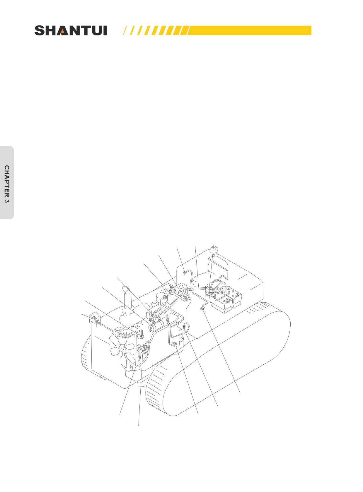
3.13.2 ELECTRIC WIRING CHART
Wire tube A
Battery relay
Horn's switch
Fuse box
Wire tube B
Water temperature sensor
Starting motor and safety relay
Horn
Headlamp
Transmission case’s safety switch
Torque converter oil temperature sensor
Wire tube C
Oil pressure gauge’s lead (connector)
Engine and voltage regulator
Figure 3-76
148

STRUCTURE & PRINCIPLE | ELECTRIC SYSTEM
3.13.3 WIRE CODES
The following wire codes can help to understand circuit diagrams
Example: wire code 70A01
“70” represents the wire’s standard cross-section, as shown in the table below:
Clutch’s
Number
Diameter of
Wire’s outer
number of
of
each strand
Main application circuit
diameter (mm)
teeth
strands
(mm)
0.5
16
0.2
2.4
0.75
24
0.2
2.6
1
32
0.2
2.8
Instrument, Lighting, Signal
1.5
30
0.25
3.1
Instrument, Lighting, Signal, Start
2.5
49
0.25
3.7
Lighting, Signal
4
59
0.3
4.5
Power supply, Start
6
84
0.3
5.1
Start, Warm-up, Charge
10
84
0.4
6.7
Start, Warm-up, Charge
16
126
0.4
8.5
Starting circuit
25
196
0.4
10.6
Starting circuit
70
360
0.5
15.7
Starting circuit
95
475
0.5
18.2
Starting circuit
“A” represents circuit or functional group, as shown in the table below:
Circuit or functional
Code
Functional assembly
group
Main circuits for starting, pre-heating, and stopping as well
A
Starting
as their control circuits, main power cables
B
Charging
Circuits for charging and charging indication etc.
Lighting by front and rear working lamps, indoor lighting,
C
Lighting
and lighting of the dashboard
Various meters and alarms, braking, steering, backing, and
D
Signal, instrument
horn etc.
E
Bond strap
Various bond straps
Windshield wiper and
F
Windshield wiper, cigarette lighter, and washer etc.
cigarette lighter
Air conditioner, radio &
G
Air conditioner, fan, heater, and radio & tape recorder etc.
tape recorder
H
Automatic control
Oil temperature sensor
“01” represents numbering within the group.
149
ELECTRIC SYSTEM | STRUCTURE & PRINCIPLE
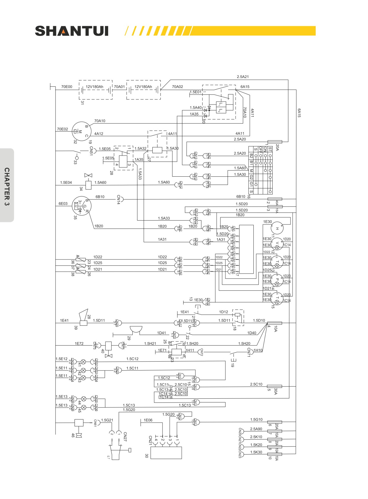
3.13.4 ELECTRIC PRINCIPLE DIAGRAM
(A)
(B)
(C)
(D)
(E)
(F)
(G)
(H)
150

STRUCTURE & PRINCIPLE | ELECTRIC SYSTEM
No.
Name
No.
Name
1-10
Fuse
33
NEUTRAL switch
11
Hour meter
34
Solenoid valve
12
Voltmeter
35
Generator
13
Oil temperature gauge
36
Oil temperature sensor
14
Engine oil pressure gauge
37
Pressure sensor
15
Water temperature gauge
38
Water/oil sensor
16
Starting switch
39
Horn
17
Alarm unit
40
Ripper tilt solenoid valve
18
Horn relay
41
Rear lamp
19
Ripper tilt switch
42
Left front lamp
20
Battery relay
43
Right front lamp
21
Horn's switch
44
Lamp on the left side
22
Reversing switch
45
Lamp on the right side
23
Relay
46
Compressor
24
Switch of front & rear lamps
47
High and Low Voltage switch
25
Side lamp switch
A
Charging indicator
26
Instrument light switch
B
Power supply
27
Starting relay
C
Neutral signal
28
Safety relay
D
Charging indicator
29
Back-up alarm
E
Earthing
Torque converter’s oil temperature
30
Thermostat
F
indicator
31
Battery
G
Engine oil pressure indicator
32
Starter
H
Engine water temperature indicator
151
MAINTENNANCE | MAINTENANCE
CHAPTER 4: MAINTENANCE
4.1 MAINTENANCE
PRECAUTIONS:
Properly servicing and maintaining the vehicle is very helpful for extending the vehicle’s service life,
ensuring personal & machine safety, increasing productivity, and improving economic benefits.
Operators and maintenance personnel, apart from reading the related requirements mentioned in
the “safety precautions”, should also observe the following.
• Servicing and maintenance personnel must be very familiar with the machine’s structure, perfor-
mance, assembly & disassembly procedures, technical requirements and precautions etc. before
doing related work. Never act blindly. For a difficult service & maintenance project, if you are not
very sure you can do it, you’d better consult your Shantui distributor. Routine maintenance is usu-
ally performed before the vehicle is started and after work each day. Before maintenance, park
the vehicle on a level ground, lower the blade and ripper, lock the locking mechanisms, and then
go ahead with the maintenance. If maintenance is performed without stopping the engine, it must
be carried out by two persons. One person sits in the cab, and the other person performs the
maintenance. Be careful not to touch the moving parts with your body.
• Prior to maintenance, thoroughly clean, brush or wash the surrounding areas of the parts to be
maintained. Pay special attention to the surrounding areas of the oil injection port, the filter, the
oil nozzle, and the housing cover, and these places must be made very clean, to prevent dust
from entering the oil.
153