Shantui SD22. Operation and Maintenance Manual - 2
CONTROLS | OPERATION
►►
Fasten the belt along your body, but don’t wind the belt
around your body. Belt length can be adjusted on both ends—
the tongue end and the buckle end. The buckle should be right
in front of your body.
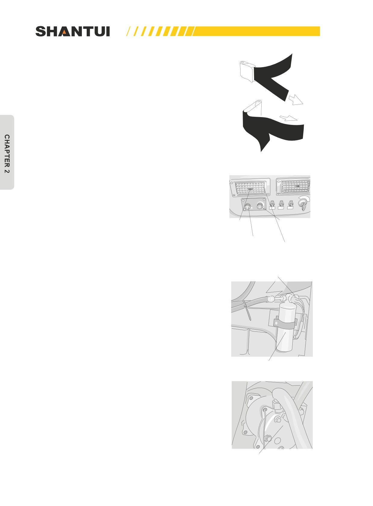
Adjust belt length using the following methods. (Figure 2-19)
• In order to shorten the belt, you can pull any of the free
ends of the belt—the buckle end or the tongue end.
• To increase the length, put the belt in right angle with the
buckle or the tongue, and pull the belt.
4. When removing the belt, raise the cusp of the buckle lever
and loosen the belt.
5. When operating a machine equipped with ROPS, be sure
to use the seat belt.
Figure 2-19
►►
Check the bolts and fasteners on the chassis and re-tight-
en if necessary, to ensure that the tightening torque reaches
2-3kgm.
►►
If the seat belt is scratched or frayed, if any fittings are bro-
ken or deformed from long service, replace the seat belt im-
mediately.
►►
The shock absorption ability of the seat meets the ISO7096
Wind direction-
A/C switch/tuning
standard.
adjusting blade
knob for refrigerat-
ing capacity
Wind direction
and wind volume
Air outlet
tuning knob
of the A/C
Figure 2-20
Liquid container’s window
The use of the air conditioner (Figure 2-20, Figure 2-21,
and Figure 2-22)
►►
When there are air bubbles in the window of the liquid
container, or when the cooling effect is not very obvious, ask a
specialised maintenance person to fix it.
Liquid container
Figure 2-21
Compressor
Figure 2-22
32
OPERATION | CONTROLS
The use of the air conditioner’s fresh air ventilator (Figure
Fresh air button
2-23)
In order to keep the air in the closed space clean, the air con-
ditioner’s fresh air ventilator is provided.
►►
When the fresh air effect is not obvious after long-time use,
please replace the internal filter of the fresh air ventilator.
Fresh air
Fresh air ventilator
Figure 2-23
Front and rear window defroster
Front window defroster (Figure 2-24)
Front window defroster uses the warm air from the A/C to heat
the front window, so as to achieve the purpose of defrosting.
A/C heater’s start valve
Figure 2-24
Rear window defroster (Figure 2-25)
Rear window defrost switch
Rear window defroster uses the resistance wire on the rear
window to heat the window after being charged with electricity,
so as to achieve the purpose of defrosting.
Rear window defroster wire
Figure 2-25
33
CONTROLS | OPERATION
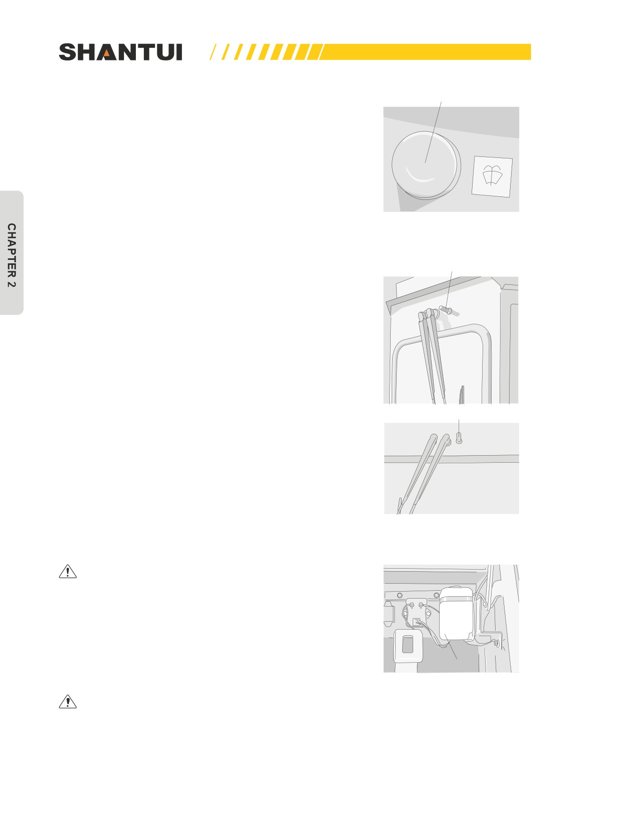
When there is dust on the front or the rear window obstructing
Front & rear windshield
washer’s button
your view, use the windshield wiper along with the windshield
washer to clean them. (Figure 2-26)
Figure 2-26
Front windshield washer nozzle
Rear windshield washer nozzle
Figure 2-26
Frequently check the liquid level of the windshield
washer tank, which is located within the battery cover on
the left side of the vehicle. (Figure 2-27)
►►
If the liquid level of the windshield washer tank is too low,
add some windshield washer. Loosen the screw on the back
Windshield washer
of the windshield washer tank, pull it out from the bottom, and
add the windshield washer from the mouth.
Figure 2-27
When the temperature is too low, be careful to prevent
the liquid from freezing.
34
OPERATION | CONTROLS
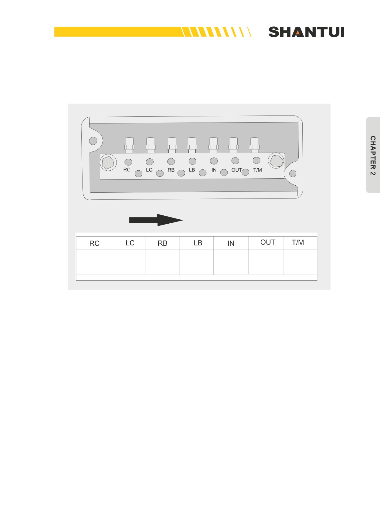
The centralized pressure measurement system (Figure 2-28)
To facilitate routine maintenance and troubleshooting, the centralized pressure measurement system
is designed. The pressure detection of all the seven key points of the entire vehicle is concentrated
on a pressure measurement plate (located on the right side of the floor frame).
FORWARD DIRECTION
Pressure
Pressure
Transmis-
Right steer-
Left steering
Left brake
Right brake
at torque
at torque
sion case’s
ing pressurepressure
pressure
pressure
converter’s
converter’s
set pres-
inlet
outlet
sure
Figure 2-28
35

CONTROLS | OPERATION
►►
The pressure measurement conditions and normal values of various pressure-measuring points:
Technical
Detection
Items to be
requirements
No.
Detection conditions
locations and
checked
(normal values)
methods
Unit: Mpa
Low speed
0.2~0.3
Oil temperature of
"OUT" Port
Torque
torque converter
1
High speed
0.46±0.15
converter
when engine is
running: 75±5°C
High speed
"IN" Port
0.85+0.2
Oil temperature of
Low speed
2.25±0.2
Transmis-
transmission case
2
"T/M" Port
sion case
when engine is
running: 75±5°C
High speed
2.4±0.25
Oil temperature of steering
Left
"LC" Port
Steering
3
clutch when engine is running:
1.6+0.3
clutch
75±5°C
Right
"RC" Port
Left
"LB" Port
Oil temperature of brake when
4
Brake
2.0+0.25
engine is running: 75±5°C
Right
"RB" Port
"LC" Port
Left
When brake’s oil pres-
Steering
Oil temperature of steering
"LB" Port
sure changes from 0,
5
baking
clutch and brake when engine
measure the pressure
pressure
is running: 75±5°C
"RC" Port
of the steering clutch:
Right
1.08~1.35
"RB" Port
Noise
When carrying out maintenance of the engine and you are exposed to noise for long periods of time,
wear ear covers or ear plugs while working. If the noise from the machine is too loud, it may cause
temporary or permanent hearing problems.
36
OPERATION | THE ELECTRIC SYSTEM (WITHOUT GPS)
2.2 THE ELECTRIC SYSTEM (WITHOUT GPS)
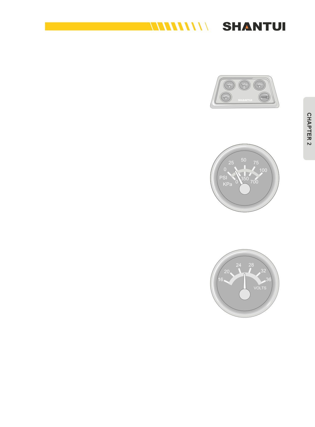
Functions of the combination meter (Figure 2-29)
The combination meter mainly includes engine oil pressure
gauge, the water temperature gauge, the oil temperature
150
180
210
180
210
250
25
50
75
100
250
140
300
0
100
F
℃
40
80
120
F
℃
60
100
150
PSI
BAR
0300 700
gauge, the voltmeter, and the hour meter.
20
24
28
32
16
36
QUARTZ
MURPHY
1
VOLTS
00
HOURS
9
0 7
10
Figure 2-29
The engine oil pressure gauge (See Figure 2-30)
The range of the engine oil pressure gauge is 0KPa-700KPa.
When the engine runs at a low speed, the oil pressure should
be bigger than 100KPa, and when the engine runs normally,
the oil pressure should be between 250KPa and 550KPa. Dur-
ing cold start, the pressure is sometimes higher, so you should
warm-up the engine first to bring the readings of the meters
within the normal operating range before starting operation.
Figure 2-30
The voltmeter (See Figure 2-31)
The range of the voltmeter is 16-36V. Before the normal op-
eration, the reading of the voltmeter is over 24V, indicating
that the battery’s voltage is normal; if the reading is below 24V,
it means that the battery’s voltage is too low and may make
it difficult to start the vehicle. If you cannot start the engine,
charge the battery.
When the machine is running normally, the engine charges the
battery, and the voltmeter’s reading is around 28V. If the volt-
age is too low or too high, find out the reason and eliminate
the problem before operation.
Figure 2-31
37
THE ELECTRIC SYSTEM (WITHOUT GPS) | OPERATION
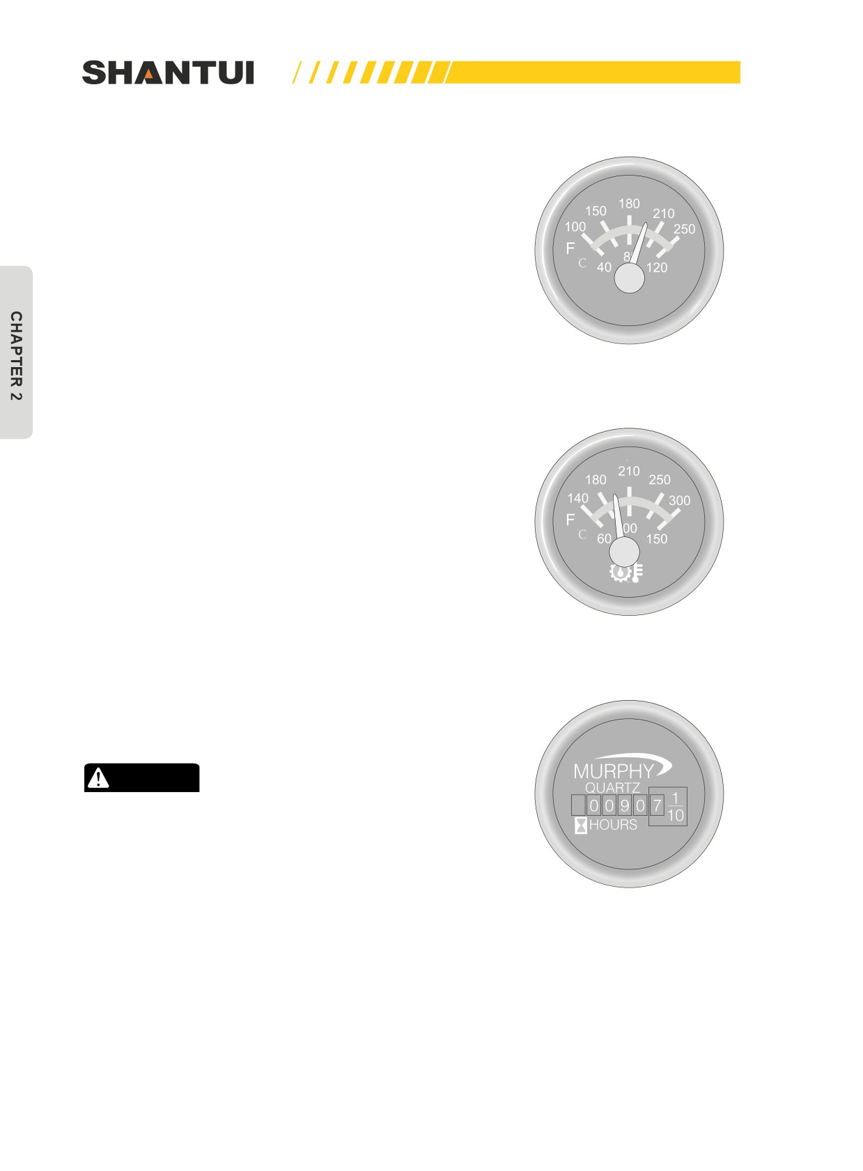
The water temperature gauge (See Figure 2-32)
The range of the water temperature gauge is 40-120°C, in-
dicating the engine’s water temperature. When the machine
runs normally, the reading of the water temperature gauge is
40-100°C. If the temperature is too high and above 100°C, re-
duce the engine speed, to bring the reading back to the normal
range; stop the vehicle to check the water level if necessary.
Figure 2-32
The oil temperature gauge (See Figure 2-33)
This indicates the oil temperature of the hydraulic torque con-
verter, and the normal operating range is 60°C-120°C. During
operation, if the temperature is too high and above 120°C, re-
duce the load, to bring the reading back to the normal range.
Figure 2-33
The hour meter (See Figure 2-34)
This meter records the operation time of the engine, to be
used as the basis for regular maintenance.
CAUTION
Check the instruments from time to time during operation,
to ensure that the operation is normal.
Figure 2-34
38
OPERATION | THE ELECTRIC SYSTEM (WITH GPS)
2.3 THE ELECTRIC SYSTEM (WITH GPS)
The bulldozer’s GPS electric system mainly includes the temperature sensor, the pressure sensor,
the fuel level sensor, the smart unit for signal collection & conversion, and the LCD smart monitor,
and the GPS smart service terminal etc. The sensors are installed in various working parts of the
bulldozer, to collect working parameters in real time, and to transmit the data through LAN; various
smart units can use each other’s data and share the same ports, to carry out various safety protec-
tion and strategic actions.
Note: If the product pictures in this manual are different from the actual products, the actual products
should be based on, and the pictures in this manual are for reference only.
This section aims to provide instructions for users to realize safe and efficient operation as well as
the effective maintenance of the vehicle’s electric system. Understanding the various precautions as
well as the repair & troubleshooting instructions can help effectively avoid various dangerous acci-
dents.
39
THE ELECTRIC SYSTEM (WITH GPS) | OPERATION
WARNING
•
Before operating or maintaining and troubleshooting the electric system, you must read
this section thoroughly.
•
The meters are precision instruments, and in the installation process you should handle
them gently. You cannot directly wash the instruments and any part of the entire electric
system with water.
•
The negative pole’s wire of the meters and the earth wire’s calibration wire should be
separately connected to the main switch end of the power supply or be connected to the
ground through a reliable nearby bond strap; never connect them together with other
equipment to the battery’s negative pole using the same wire.
•
The connection of all the signal lines of meters (switch value and analog value) should be
reliable and firm.
•
The four screws connecting the dashboard and the instrument box should be tightened to
ensure the normal use of the meters.
•
The installation of all the sensors should ensure that the sensor’s outer threads and their
surface are connected properly, to ensure that the sensor’s bond strap is in good condi-
tion. (We don’t recommend the use of sealant on the mounting face)
•
Before the installation of cables, the installation points of all the bond straps (the surface
in contact with the cable’s terminals) must be rigorously treated to remove the paint and
the oxidized substance, to ensure that the contact surface is smooth and flat and has
good conductance.
•
The protective insulating rubber cover at the end of all the bond straps should not be too
long to negatively affect the normal connection of the bond strap surface.
•
When multiple bond straps are installed at one bond strap point, they should be alternated
with each other, to ensure the complete contact after installation.
•
The bond strap’s mounting pedestal should be fully soldered, and should not be cold-
soldered or contain slag.
•
Ensure that the power switch has good contact during operation, and the contact resis-
tance of the switch’s contact should be within 0.001Ω.
CAUTION
• To avoid causing vehicle-locking fault, the users are strictly forbidden to modify or remove
the GPS system’s elements and circuits.
40
OPERATION | THE ELECTRIC SYSTEM (WITH GPS)
2.3.1 PRECAUTIONS FOR TURNING ON AND OFF THE MAIN MACHINE
STARTING UP——
1. Put the mains switch to ON
2. Apply the brake
3. Adjust the seat and tighten the seat belt
4. Ensure that all the work equipments (blade and ripper etc.) are on the ground
5. Put the gear on NEUTRAL
6. Ensure that the control levers (for blade and ripper etc.) are locked
7. Ensure that people around the bulldozer are in safe places
8. Put the valve control to LOW IDLE
9. Put the key switch to ON, and the monitor will begin self-test
10. Put the key switch to START to start the engine: in winter when temperature is low, start the
engine after the automatic warm up
WARMING UP——
1. Warm up the machine for 5min when the engine is idling
2. Unlock the control levers of the work equipments, and cycle the control levers, to ensure that
the work oil runs through all the cylinders and pipes
3. Check the instruments and monitors
WORKING——
1. Observe the surroundings of the bulldozer to ensure clear vision
2. Raise all the work equipments (blade and rippers etc.)
3. Ensure that the walking control lever is being pressed down
4. Release the brake
5. Change the gear to the needed position
6. Release the walking control lever to begin operation appropriate to the conditions
SHUTTING DOWN——
STEPS
REMARKS
1. Stop the bulldozer in a level area
2. Apply the brake
3. Reduce the speed of all the hydraulic elements
4. Let the engine idle for 5min
5. Put the key switch to OFF
6. Get off the vehicle safely with the help of hands
7. Observe if there are obvious issues around the bulldozer that need
to be addressed after operation
41
THE ELECTRIC SYSTEM (WITH GPS) | OPERATION
2.3.2 THE ENVIRONMENTAL REQUIREMENTS OF THE CONTROLLERS AND MONITORS
1. Power supply: 18~32VDC
2. Operating temperature: -30~+70°C
3. Storage temperature: -40~+85°C
4. Relative humidity: (30~90)%RH
5. Atmospheric pressure: 86~106KPa
6. Protection class: IP65
When one or more of the above parameters is out of the required range, the electric system may not
work normally or may become damaged. Please use the system strictly following the above require-
ments on the operating environment, to ensure that the system can work normally.
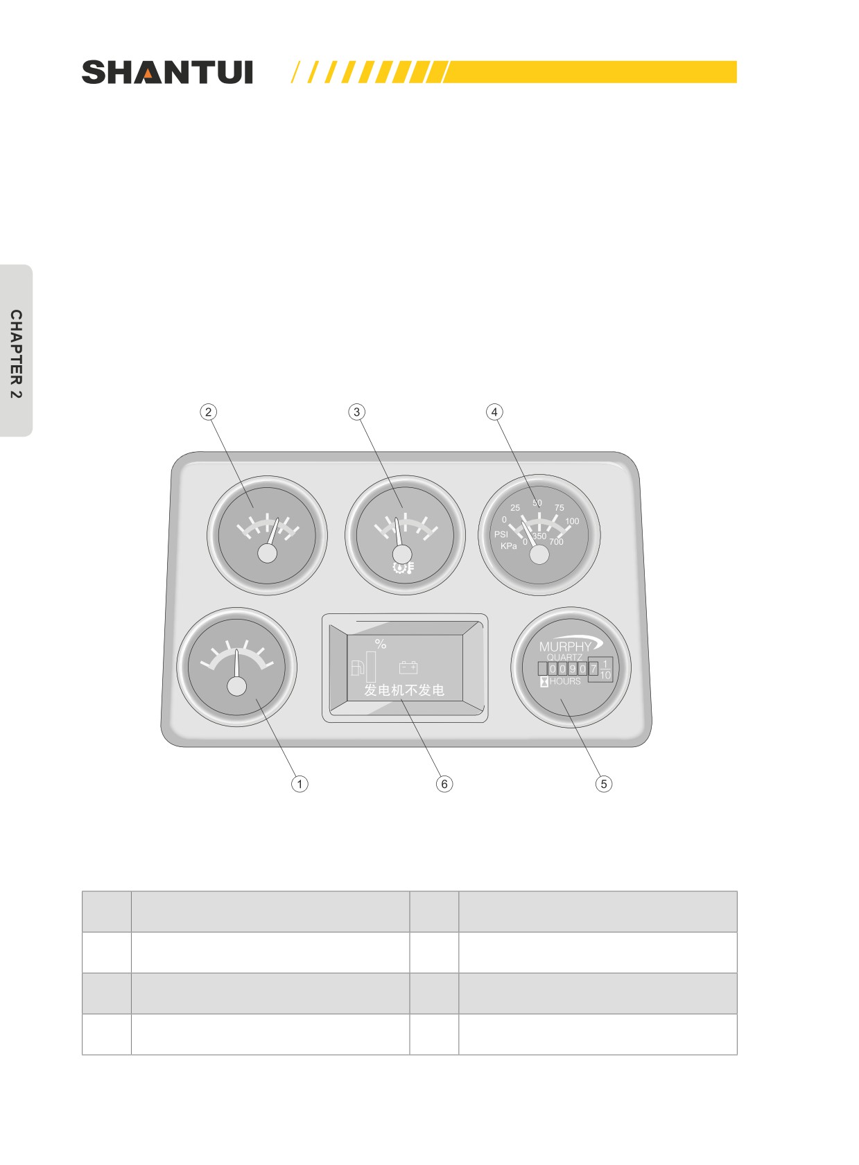
2.3.3 DESCRIPTION OF THE MONITOR PANEL
180
210
150
210
180
250
100
250
140
300
F
F
80
100
℃
40
120
℃
60
150
24
28
20
32
0 rpm
16
36
28.5v
VOLTS
Figure 2-35: GPS system’s monitor panel
This monitor panel consists of 5 dial pointers and 1 LCD smart monitor, as shown in Figure 2-35.
No.
Name
No.
Name
Meter displaying water temperature of
1
Meter displaying system voltage
2
the engine
Meter displaying oil temperature of the
3
4
Meter displaying engine oil pressure
hydraulic torque converter
5
Hour meter
6
LCD Smart monitor
42
OPERATION | THE ELECTRIC SYSTEM (WITH GPS)
2.3.4 DESCRIPTION OF THE SWITCH BUTTON PANEL
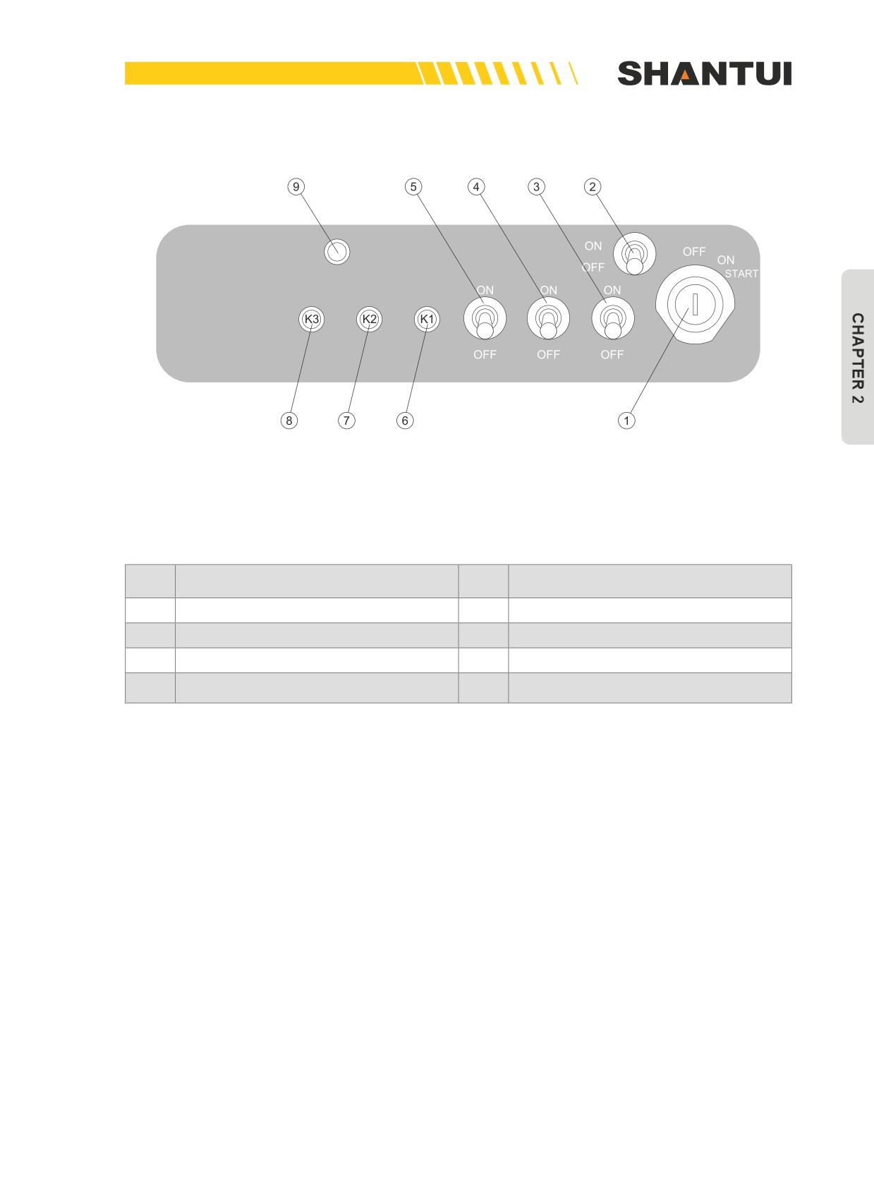
Figure 2-36: GPS system’s switch button panel
This switch panel consists of 3 reset switch buttons, 4 toggle switches and 1 key switch, as shown in
Figure 2-36:
No.
Name
No.
Name
1
Key starting switch
2
Side lamp switch
3
Front lamp switch
4
Rear lamp switch
5
Instrument light switch
6
K1—LCD smart monitor’s Mute/OK key
K3—LCD smart monitor’s Menu/Left &
7
K2—LCD smart monitor’sUP/Down key
8
Right key
Operation of the reset switch buttons:
1. K1 Mute/Confirmation Key:
a. When there is a warning buzz, activating this key can stop the buzz;
b. Choose the confirmation function in the menu, to enter the next level of menu;
c. In the setup state, press this key to confirm the current operation.
2. K2 Up/Down Key:
a. Move the cursor up or down;
b. Display the next page or the previous page;
c. Change value (i.e. the increase or decrease function).
3. K3 Menu/Left and Right Key:
a. Enter the main menu, exit to the last menu, and return to the main window;
b. Move the cursor left or right to select the numerical digits.
43
THE ELECTRIC SYSTEM (WITH GPS) | OPERATION
2.3.5 OPERATION OF THE ELECTRIC SYSTEM
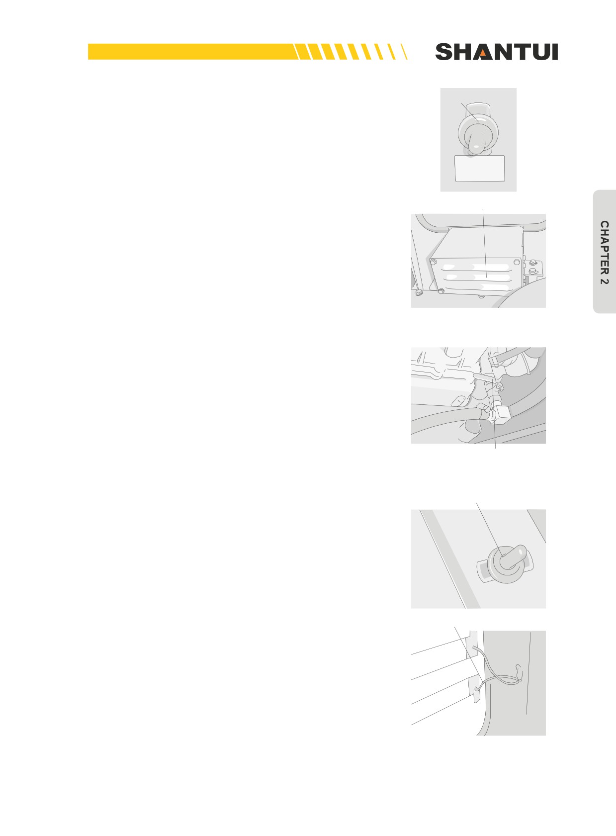
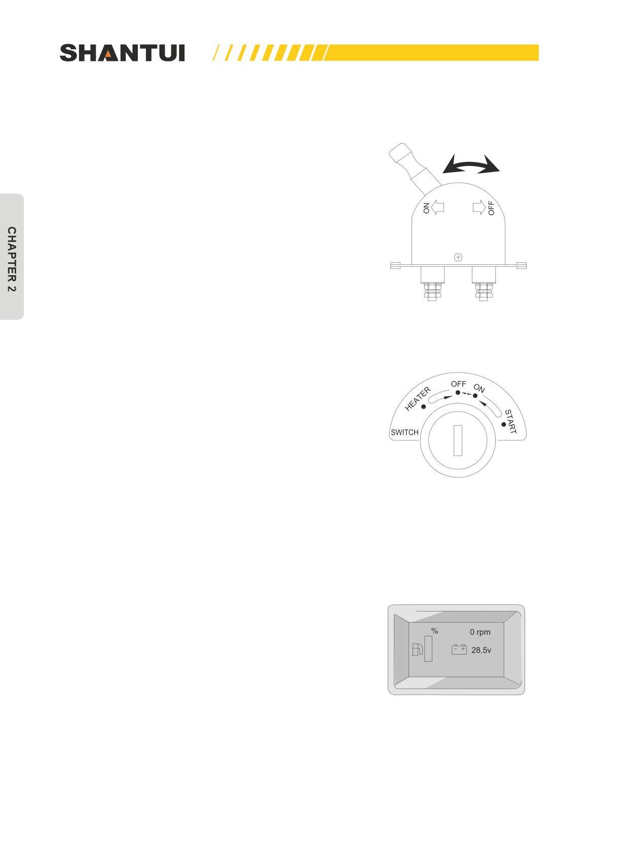
The power supply’s main switch
The power supply’s main switch is installed near the battery,
to connect the battery’s negative terminal and the bulldozer’s
body; the power supply’s main switch has a switch-blade struc-
ture, and has two positions: ON and OFF (as shown in Figure
2-37); When the bulldozer does not work for a long time, you
should push the knob of the power supply’s main switch to the
OFF position, to reduce the battery’s consumption. Before the
bulldozer is started, push the knob of the power supply’s main
switch to the ON position.
Figure 2-37: Power switch
Key starting switch
The starting switch is located on the instrument box’s switch
panel. It has four positions (as shown in Figure 2-38), which
are the HEATER position, the OFF position, the ON position
and the START position. When the starting switch is in the
OFF position, the system is in the power off state; when you
insert the key, and turn the starting switch from OFF to ON,
the entire electric system is powered on, and after a short self-
test, the monitors enter the main working window, as shown
in Figure 2-38. Turn the starting switch from ON to START,
Figure 2-38: Key starting switch
and release the key after ensuring that the engine is started,
the starting switch will automatically return to the ON position.
When the starting switch is turned to the OFF position, the en-
gine will stop working.
Smart monitor
The main working window of the smart monitor displays the
fuel level (%), the system’s voltage, the current gear position,
the engine speed and the warnings, as shown in Figure 2-39.
The main functions of this monitor are as follows:
a. Displays the operation the vehicle’s parameters in real time
Engine does not
b. Provide warning information
generate power
c. System setup and vehicle management
Figure 2-39: Smart
monitor’s window
44
OPERATION | THE ELECTRIC SYSTEM (WITH GPS)
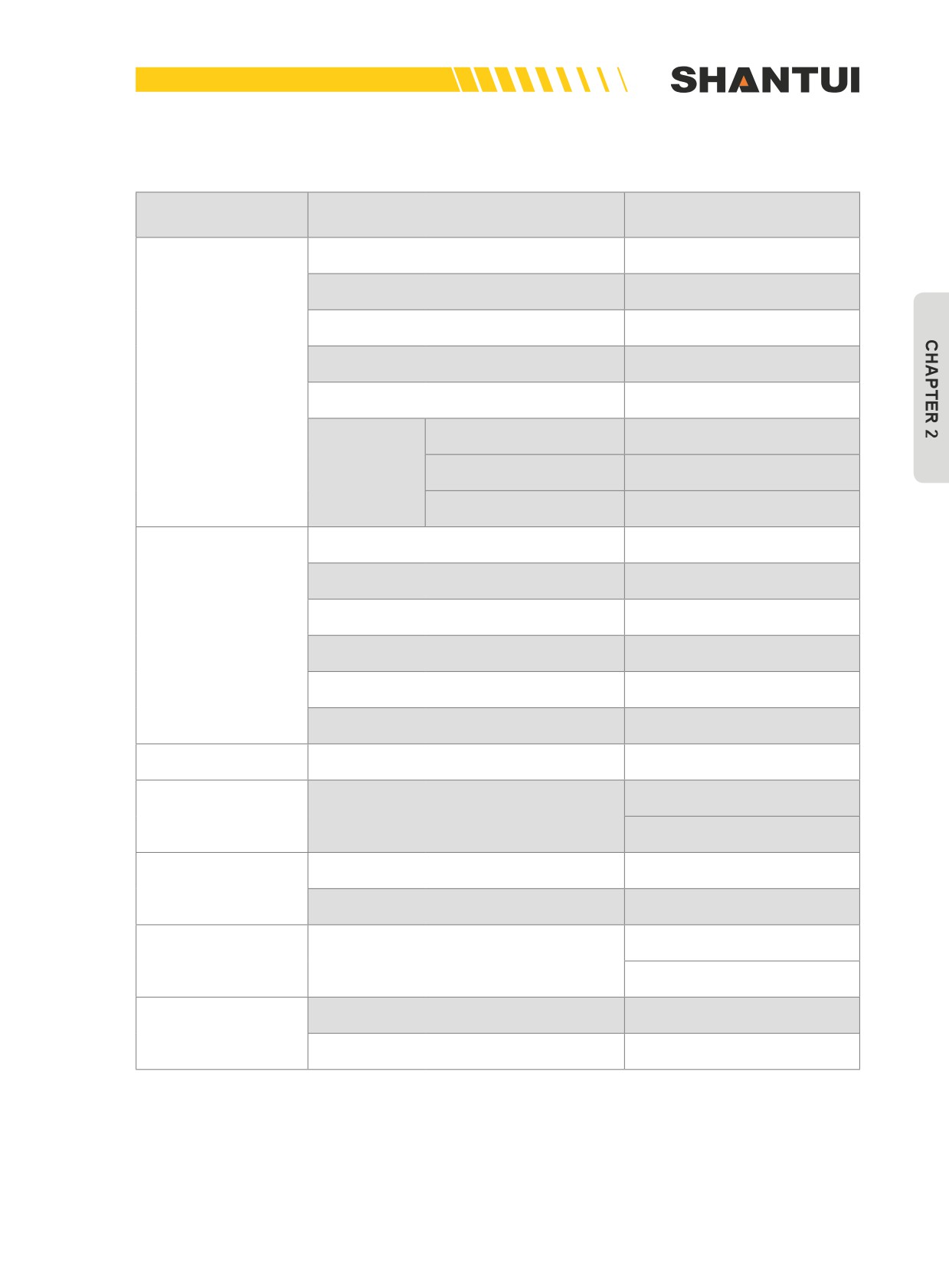
1. The smart monitor’s working menu is as follows:
Window
Check content
Setup management
Fuel level
%
Engine speed rpm
System voltage
Warm-up indication
Main window
Gear position indication
Alarm for parameters out
of range
Fault alarm
Device fault alarm
Vehicle management
alarm
Fuel level
%
Cooling water temperature
°C
Torque converter’s oil temperature
°C
Operation parameter
Engine oil pressure Bar
Engine speed rpm
System voltage
Alarm parameters
Flywheel’s number of teeth
Chinese
User setup
Language setup
English
Flywheel’s number of teeth
Alarm parameter setup
(range: 000.00-300.00)
System setup
Testing information (backup)
Vehicle is unlocked on-site to
be opened
Vehicle management
On-site unlocking (dynamic password)
Vehicle is unlocked on-site to
be closed
Hardware: D2460-00030
Monitor’s information
Software: V10
45
THE ELECTRIC SYSTEM (WITH GPS) | OPERATION
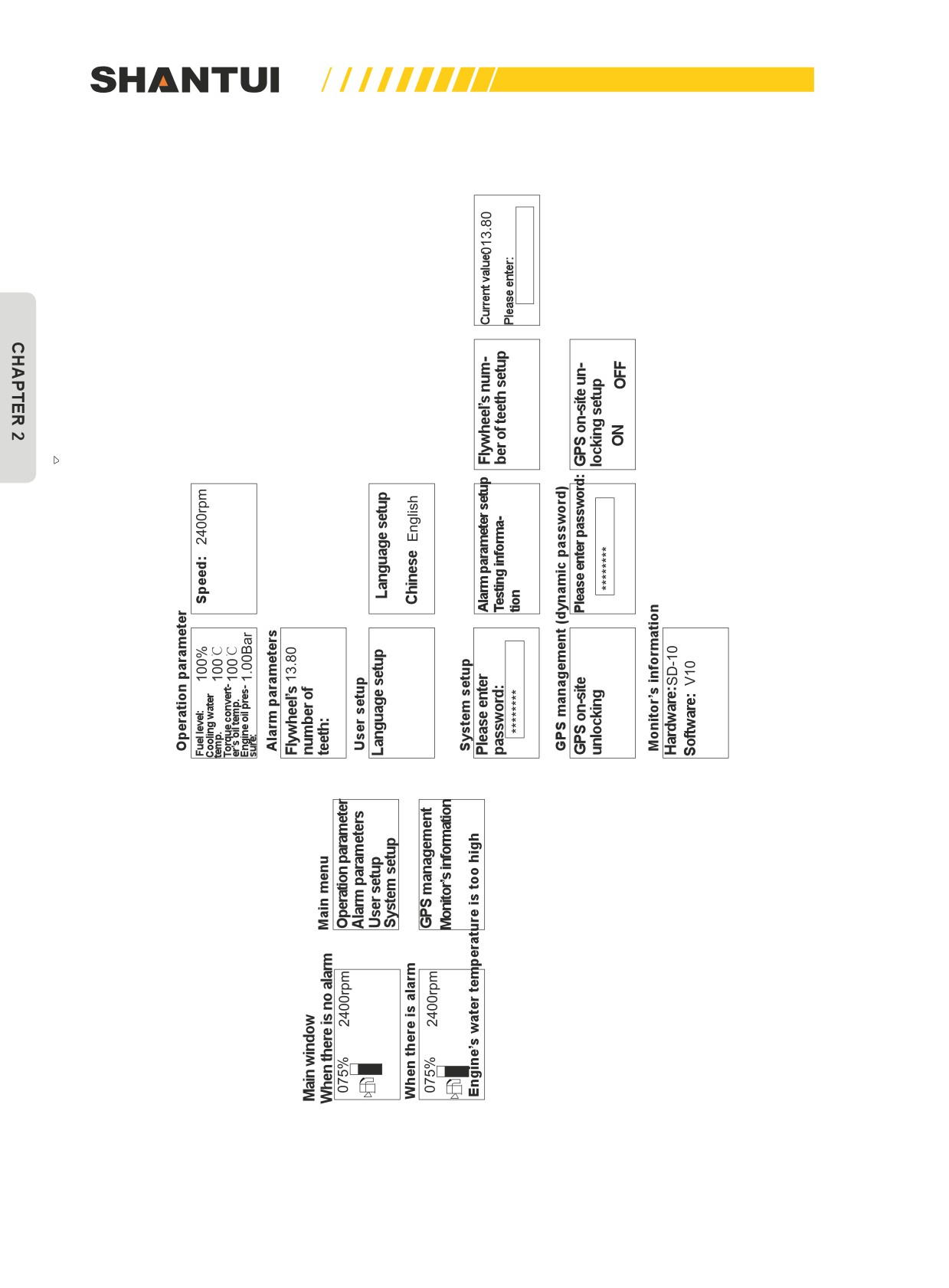
2. Illustration of work menu cascade (Chinese)
46
OPERATION | THE ELECTRIC SYSTEM (WITH GPS)
3. Warnings
When the LCD smart monitor detects a fault of the bulldozer, it will display the related warnings in
its main window, and give out the buzz to alert the operator. Types of the warning information are as
follows:
Chinese
English
水温传感器断路
Water temp sensor open
水温传感器短路
Water temp sensor short
发动机水温高
Engine water too hot
燃油传感器断路
Fuel sensor open
燃油传感器短路
Fuel sensor short
燃油液位低
Fuel level low
油温传感器断路
Oil temp sensor open
油温传感器短路
Oil temp sensor short
传动油温高
Trans oil temp too high
油压传感器断路
Oil pressure sensor open
油压传感器短路
Oil pressure sensor short
机油压力过低
Engine oil pressure low
预热进行中
Warming
空档
Neutral
发电机不发电
Alternator failed
车辆故障:0010
Vehicle fault: 0010
车辆故障:0011
Vehicle fault: 0011
车辆故障:0012
Vehicle fault: 0012
车辆故障:0020
Vehicle fault: 0020
车辆故障:0030
Vehicle fault: 0030
车辆故障:0031
Vehicle fault: 0031
车辆故障:0032
Vehicle fault: 0032
47
THE ELECTRIC SYSTEM (WITH GPS) | OPERATION
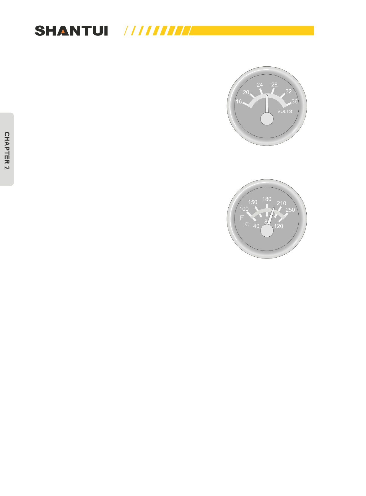
Check system voltage
The dial pointer intuitively displays system voltage in real time
(as shown in Figure 2-40). When the key starting switch is
in OFF, the pointer is back to zero, and when it is in ON, the
pointer points at around 24V. When the engine is running,
pointer should point at around 28V. This meter has a backlight
in purple red, to facilitate use during nighttime.
The LCD smart monitor’s main window dispalys system volt-
age.
When the system voltage is lower than 22V, the charging in-
dicate on the smart monitor will blink, the warming message
“System voltage low” will occur, and the buzzer will sound.
Figure 2-40: Meter displaying
system voltage
Check the temperature of the cooling water
The dial pointer displays the temperature of the cooling water
in real time (as shown in Figure 2-41), and the display range is
40-120°C. This meter has a backlight in purple red, to facilitate
use during nighttime.
The LCD smart monitor displays the engine’s cooling water
temperature in real time, and you can check it out by entering
the menu of operation parameters.
1. When the water temperature sensor’s circuit is open, the
pointer is back to zero, the smart monitor gives warning
Figure 2-41: Meter displaying the
“Water temperature sensor’s circuit is open”, and the buzz-
temperature of the cooling water
er sounds.
2. When the water temperature sensor’s circuit is short, the
pointer is at full scale, the smart monitor gives warning
“Water temperature sensor’s circuit is short”, and the buzz-
er sounds.
3. When the water temperature sensor detects a temperature
≥100°C, the smart monitor gives warning “Engine water
temperature high”, and the buzzer sounds.
4. Cancelling a warning should be done about 10s later after
the parameter is back to normal.
5. Pressing the K1 key (as shown in Figure 2-36) can shield
the buzzer’s sound.
48
OPERATION | THE ELECTRIC SYSTEM (WITH GPS)
Check the oil temperature of the torque converter
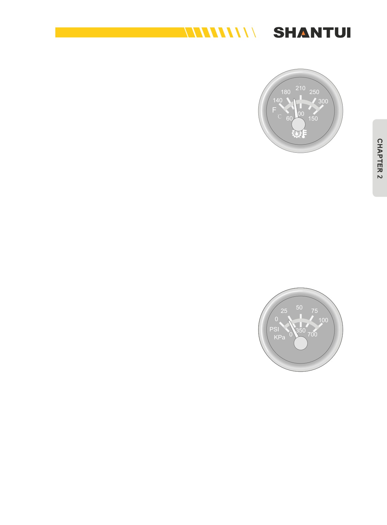
The dial pointer displays the hydraulic oil’s temperature intui-
tively and in real time (as shown in Figure 2-42), and the dis-
play range is 60-150°C. This meter has a backlight in purple
red, to facilitate use during nighttime.
The LCD smart monitor displays the oil temperature of the
torque converter in real time, and you can check it out by en-
tering the menu of operation parameters.
1. When the oil temperature sensor’s circuit is open, the
pointer is back to zero, the smart monitor gives warning
“oil temperature sensor’s circuit is open”, and the buzzer
sounds.
Figure 2-42: Meter displaying
hydraulic oil temperature
2. When the oil temperature sensor’s circuit is short, the
pointer is at full scale, the smart monitor gives warning
“oil temperature sensor’s circuit is short”, and the buzzer
sounds.
3. When the oil temperature sensor detects a temperature
≥120°C, the smart monitor gives warning “Transmission oil
temperature high”, and the buzzer sounds.
4. Cancelling a warning should be done about 10s later after
the parameter is back to normal.
5. Pressing the K1 key (as shown in Figure 2-36) can shield
the buzzer’s sound.
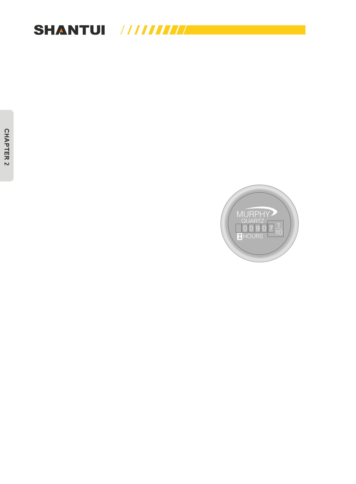
Check engine oil pressure
The dial pointer intuitively displays engine oil pressure in
real time (as shown in Figure 2-43), and the display range is
0-700KPa. This meter has a backlight in purple red, to facili-
tate use during nighttime.
The LCD smart monitor displays engine oil pressure in real
time, and you can check it out by entering the menu of opera-
tion parameters.
Figure 2-43: Meter displaying
engine oil pressure
49
THE ELECTRIC SYSTEM (WITH GPS) | OPERATION
1. When the oil pressure sensor’s circuit is open, the pointer
is back to zero, the smart monitor gives warning “oil pres-
sure sensor’s circuit is open”, and the buzzer sounds.
2. When the oil pressure sensor’s circuit is short, the pointer
is at full scale, the smart monitor gives warning “oil pres-
sure sensor’s circuit is short”, and the buzzer sounds.
3. When oil pressure sensor detects a pressure ≤1Bar, the
smart monitor gives warning “Engine oil pressure too low”,
and the buzzer sounds.
4. Cancelling a warning should be done about 10s later after
the parameter is back to normal.
5. Pressing the K1 key (as shown in Figure 2-36) can shield
the buzzer’s sound.
Check bulldozer’s operation hours
The dial pointer intuitively displays the bulldozer’s operation
hours in real time (as shown in Figure 2-44), the time is show
in hours, and the smallest display unit is 1/10h.
Check fuel level
Fuel level is displayed as a percentage in real time in the
smart monitor’s main window (as shown in Figure 2-39).
1. When fuel level sensor’s circuit is open, the smart moni-
tor gives warning “Fuel sensor is open”, and the buzzer
sounds.
Figure 2-44: Hour meter
2. When fuel level sensor is short, the smart monitor gives
warning “Fuel sensor is short”, and the buzzer sounds.
3. When fuel level sensor detect fuel level ≤10%, the smart
monitor gives warning “Fuel level low”, and the buzzer
sounds.
4. Cancelling a warning should be done about 10s later after
the parameter is back to normal.
5. Pressing the K1 key (as shown in Figure 2-36) can shield
the buzzer’s sound.
Check engine speed
Engine speed is displayed in real time in the smart monitor’s
main window (as shown in Figure 2-39).
50
OPERATION | THE ELECTRIC SYSTEM (WITH GPS)
Definitions and descriptions of other warnings
1.
When the engine does not have output, the smart monitor gives warning “Engine does not gen-
erate power”, and the buzzer sounds.
2.
When the smart monitor detects that the gear is in the NEUTRAL position, it blinks to remind
“NEUTRAL position”; and when it detects a gear, it blinks to remind the gear.
3.
When warm-up is normal, the smart monitor reminds “Warming up”, and also blinks to remint it.
4.
When the bulldozer’s smart monitor gives warning “Vehicle fault 0010”, all the dial pointers (ex-
cept for the meter displaying battery voltage) are back to zero. You need to contact your equip-
ment supplier.
5.
When the bulldozer’s smart monitor gives warning “Vehicle fault 0011”, all the dial pointers (except
for the meter displaying battery voltage) are back to zero. The GPS antenna is not properly con-
nected, and you should check it out and fix it.
6.
When the bulldozer’s smart monitor gives warning “Vehicle fault 0012”, all the dial pointers (ex-
cept for the meter displaying battery voltage) are back to zero. The communication card of the
smart service system does not work properly, and you should check it out and fix it.
7.
When the bulldozer’s smart monitor gives warning “Vehicle fault 0020”, all the dial pointers
(ex-
cept for the meter displaying battery voltage) are back to zero, and the engine cannot be started
normally. You need to contact your equipment supplier.
8.
When the bulldozer’s smart monitor gives warning “Vehicle fault 0030”, all the dial pointers
(ex-
cept for the meter displaying battery voltage) are back to zero, and the engine cannot be started
normally. You need to contact your equipment supplier.
9.
When the bulldozer’s smart monitor gives warning “Vehicle fault 0031”, all the dial pointers
(ex-
cept for the meter displaying battery voltage) are back to zero, and the engine cannot be started
normally. You need to contact your equipment supplier.
10. When the bulldozer’s smart monitor gives warning “Vehicle fault 0032”, all the dial pointers
(ex-
cept for the meter displaying battery voltage) are back to zero, and the engine cannot be started
normally. You need to contact your equipment supplier.
CAUTION
The display of the oil level gauge has a delay. Please pay special attention to this during op-
eration.
51
THE ELECTRIC SYSTEM (WITH GPS) | OPERATION
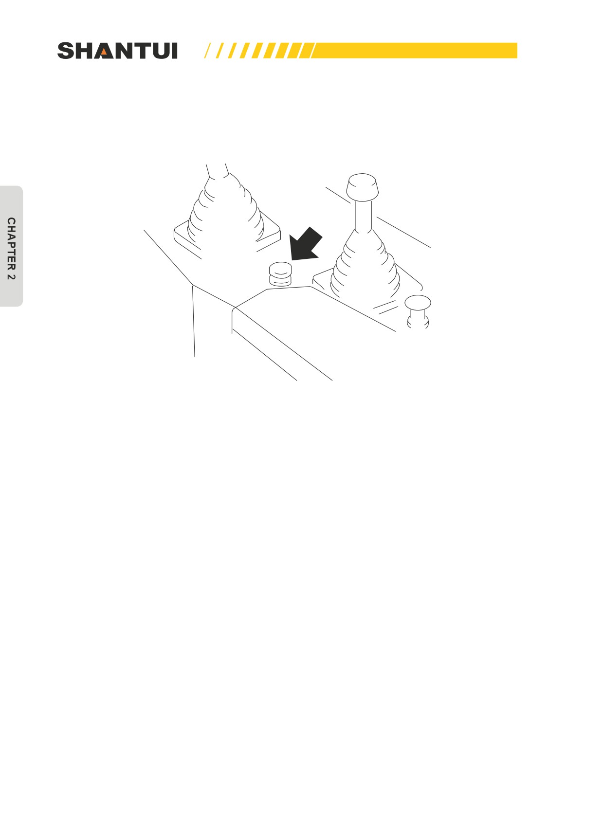
2.3.6 OPERATION OF THE HORN BUTTON
When you press this button (as shown in Figure 2-45), the horn will sound.
Figure 2-45: Horn button
52
OPERATION | THE ELECTRIC SYSTEM (WITH GPS)
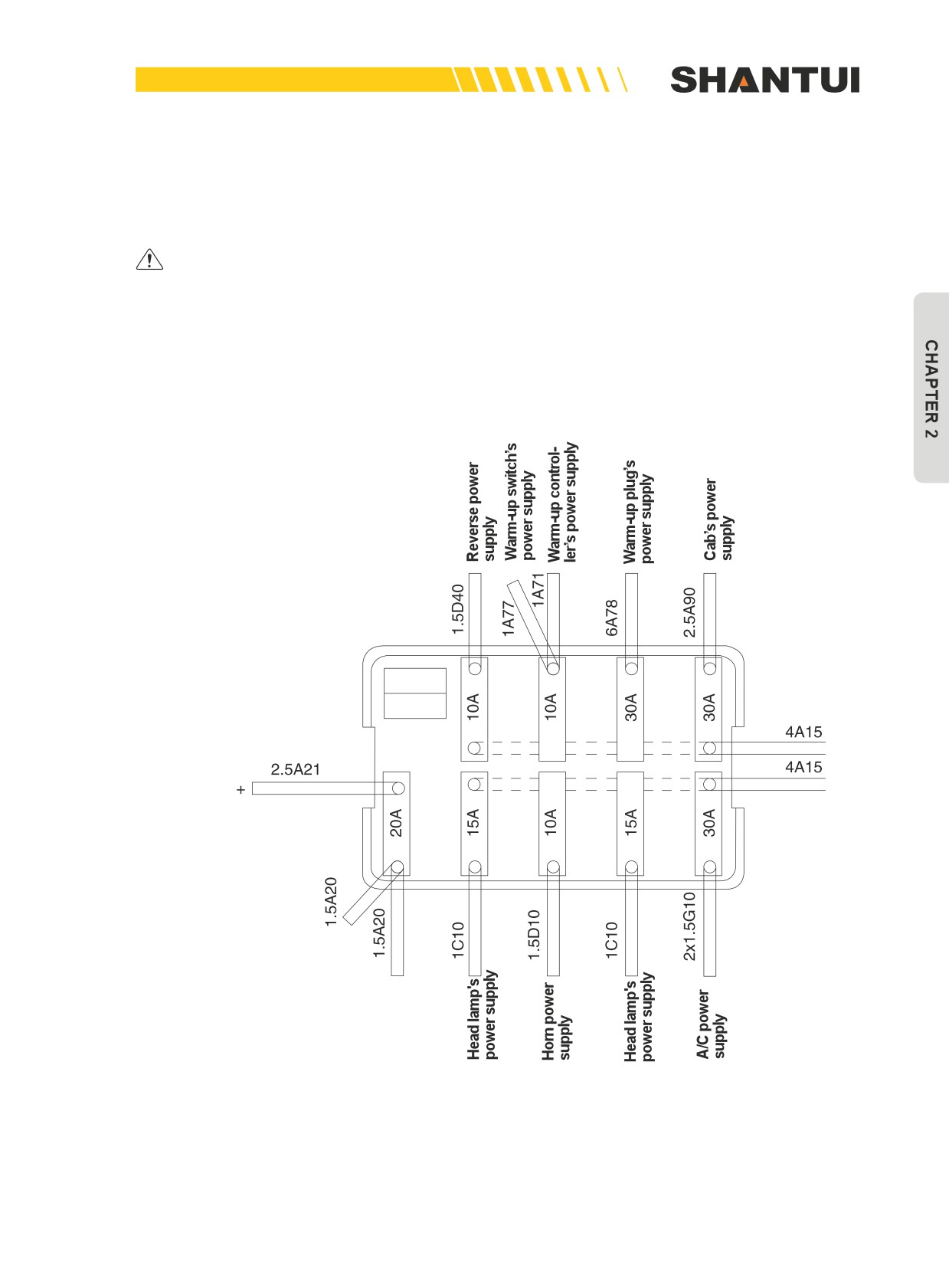
2.3.7 PRECAUTIONS FOR FUSE BOX
If a fuse becomes corroded, or white powder can be seen, or a fuse is loose in the holder, replace
the fuse.
►►
Replace a fuse with another of the same capacity.
Before replacing a fuse, be sure to turn off the starting switch.
The arrangements and capacities of the fuses are shown in Figure 2-46:
FUSE BOX WIRING CHART
To Battery
Figure 2-46: Fuse box wiring chart
53
THE ELECTRIC SYSTEM (WITH GPS) | OPERATION
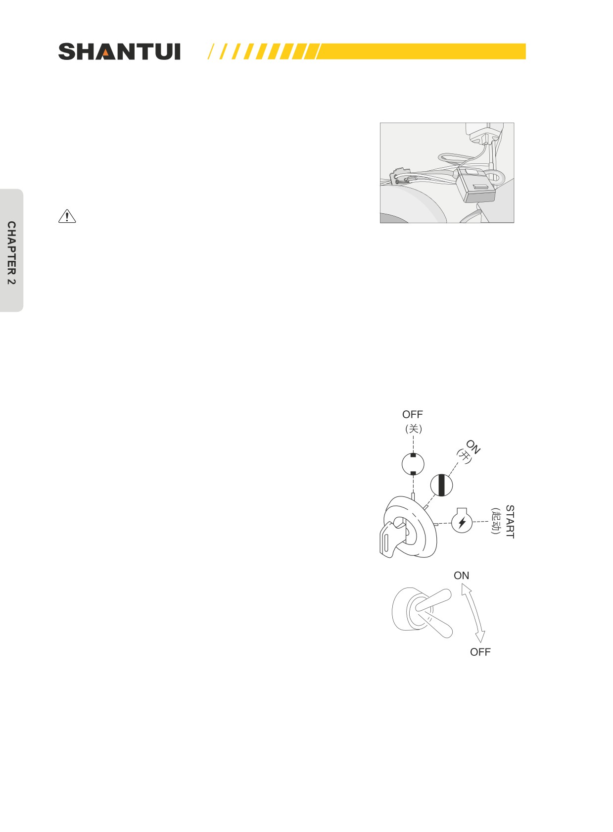
2.3.8 IN-LINE FUSE
There are some in-line fuses in the instrument box of this ma-
chine, as shown in Figure 2-47. When the meters and the GPS
system do not have power supply, you need to check the cor-
responding inline fuses to see if they are already blown. Re-
place the fuses after eliminating the corresponding faults.
►►
Replace a fuse with another of the same capacity.
Before replacing a fuse, be sure to turn off the start-
ing switch.
Figure 2-47: Illustration of
In-line fuse
2.3.9 POWER SOCKETS
This machine provides the 24V power socket in the accumula-
tor box. If you repair the machine during nighttime and tempo-
rarily need the 24V power supply, you can open the accumula-
tor box’s cover to see the 24Vpower socket.
2.3.10 WARM-UP AND START
Turn the key switch to ON (Figure 2-48) to turn on the warm-
up switch (Figure 2-48). When the engine’s water temperature
is above 0°C, the system will not enter the warm-up state, and
will only indicate it by lighting up the warm-up indicator for 2
seconds. When the engine’s water temperature is below 0°C,
the system will automatically enter the warm-up state, and the
duration that the indicator is on is the warm-up time, which is
related to the voltage. When the voltage is 24V, the warm-up
time is 26±2 seconds.
Figure 2-48
54
OPERATION | THE ELECTRIC SYSTEM (WITH GPS)
When the indicator is off, it means that the warm-up is over, and the engine can be started; if the
engine is not started within 30 seconds (during this period the warm-up plug remains electrified), the
system will automatically stop working; if the engine is started, the indicator will be on, the warm-
up plug will continue to be electrified, the solenoid valve will automatically connect the oil circuit,
the system will automatically enter the post-heating stage (during this stage the warm-up plug, the
solenoid valve and the indicator remain electrified), and the post-heating time is determined by the
engine’s water temperature. When the battery’s voltage is below 15V or when the temperature sen-
sor has an open circuit, the system will not enter the warm-up state, and the indicator will blink for
15 seconds to alarm.
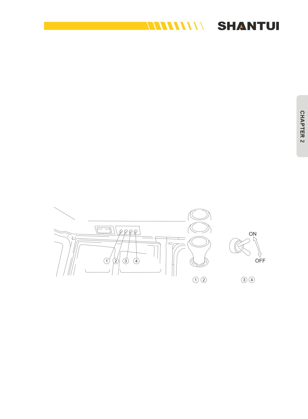
2.3.11 CAB’S HEAD LAMP SWITCH
When the switch is pulled to the “ON” position, the cab’s head lamp lights up. as shown in Figure (2-
49)
2.3.12 WINDSHIELD WIPER SWITCH
These switches (as shown in Figure 2-49) are used to operate the following windshield wipers:
(1)—Rear Window Wiper
(2)—Front Window Wiper
High speed
Low speed
OFF
Head lamp switch, Fan switch
Windshield wiper switch
Figure 2-49
55
THE ELECTRIC SYSTEM (WITH GPS) | OPERATION
2.3.13 DESCRIPTION OF THE BOND STRAPS OF CONSTRUCTION MACHINERY’S ELECTRIC
SYSTEM
The bond straps of construction machinery’s electric system can have many types of faults. For ex-
ample, the engine does not have sufficient power or is not easy to be started, the lamps are not lit
up, the meters do not have accurate displays or are easy to give false alarms, etc.
The construction machinery’s electric system uses the low-voltage DC power supply, adopts the se-
rial connection, parallel connection or mixed connection circuits, and all the circuits have a positive
terminal and negative terminal. All the circuits from the loads would need to be directly connected
to the battery’s negative terminal through wires. If separate wiring is adopted, there would be more
than one hundred wires on the battery. In order to save the wires and to facilitate installation, the cir-
cuits of general construction vehicles would use a single wire, which means that the battery’s posi-
tive terminal is directly connected to various electric devices, the battery’s negative terminal is di-
rectly strapped to the metal part of the vehicle’s frame, the negative terminals of electric devices are
strapped to the nearby metal part of the vehicle’s frame, and the metal part of the engine and the
chassis (beam frame) is used as the public pathway. This type of connection in which the negative
terminal is connected to the body of the vehicle is called bond strapping. It is also known as earthing
or metal connecting. Negative terminal’s bond strapping has a number of benefits including less in-
terference to the electronic devices, less electrochemical corrosion to frame and body, and firm con-
nection. Today most construction machines and vehicles adopt negative terminal’s bond strapping.
The body of a construction machine generally has more than two main bond straps. One of them
is the battery’s negative terminal wire, and the other is the bond strap between the engine and the
beam. The form of these bond straps is different from ordinary wires. They are usually copper wires
above 50mm2, and the current carrying capacity is large. Malfunction of bond strap is very easy to
occur. For example, the failure to clean the paint on the frame before the entire vehicle leaves the
factory, a loose fastening bolt of the engine’s bond strap, the makeshift installation during the recon-
nection of bond straps, or the increased resistance of bond strap’s connector due to corrosion all
can cause improper contact, forcing the current to try to go through other circuits, causing voltage
drop or failure. Malfunction of bond straps can cause many obvious or hidden faults to circuits. In
the ignition system, if engine’s bond strap does not function properly, the engine may not be started.
In the starting circuit, if engine’s bond strap does not function properly, the starter’s speed will be re-
duced, the armature will be heated, and over time, it will be very easy to have the starter burned. In
the lighting circuit, if the bond straps of the lamps do not function properly, the lamps may not be lit
or the lamps may be dim. Therefore, knowing the role of bond straps can avoid many faults and the
wrong judgment during the troubleshooting of the electric system.
56
OPERATION | OPERATION
2.4 OPERATION
WARNING
Please read and make sure that you understand the SAFETY section before reading this sec-
tion.
2.4.1 CHECK BEFORE STARTING ENGINE
►►
Form a habit to check before starting engine. Never be imprudent and careless. This is
good for the safety of both people and vehicle.
Check oil or water leakage
Before starting the engine, look around the machine and under the machine to check for loose nuts
and bolts, or leakage of oil, fuel, or coolant, and check condition of the work equipment and hydrau-
lic system. Check also for loose wiring, play, and collection of dust at places which reach high tem-
peratures.
Check bolts and nuts
Check for loose nuts and bolts, and tighten them if necessary. Pay special attention to air cleaner,
carrier roller bracket and track shoe bolts.
Check electric circuits
Check to see if the wires are damaged or shorted or if the terminals are loose.
57
OPERATION | OPERATION
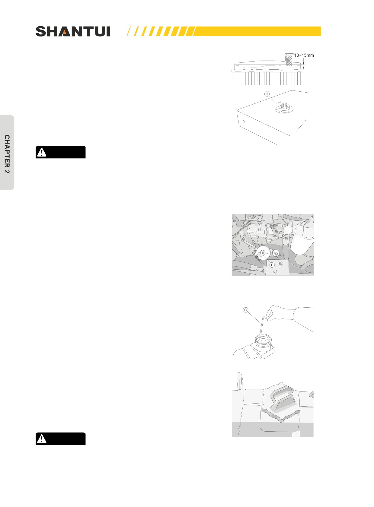
Check cooling water level (Figure 2-50)
Turn open the radiator cap (1) (Figure 2-50), and check if the
water is at the required level. Add water if necessary.
Add cooling water after the engine has stopped. Add water to
the sub-tank to the full (until the water overflows), and then
start the engine and let it idle for 5min and check again. If the
water level is lower than required, continue to add water. If
the water added is increased abnormally, look for leakage and
solve it in time.
CAUTION
Figure 2-50
When cooling water is overheated, turn the cap (1) loose
slowly, to release the internal pressure before opening it,
to avoid boiling water from spurting out to have people in-
jured.
Check oil level in engine oil pan (Figure 2-51)
When the engine has stopped, take out the dipstick(G), and
check the oil level on the side marked “Engine stopped”. When
the engine is idling, check to see if the engine oil pressure
gauge and water thermometer are within the normal range
first, and then take out the dipstick (G) to look at the oil level
on the side marked “Engine idling”. If oil needs to be added,
open the injection mouth to add oil. The types of engine oil
Figure 2-51
depend on the ambient temperature. See the “USE OF FUEL,
COOLANT AND LUBRICANTS ACCORDING TO AMBIENT
TEMPERATURE”. When checking oil level, park the vehicle on
a level ground. When adding engine oil, do not let the oil level
be higher than the “(H)”mark. When checking oil level, do not
rely on engine oil level monitor alone.
Check fuel level
Remove the fuel tank cap, and pull out the dipstick (G) (as
shown in Figure 2-52) to check the oil level.
After completing work, fill the fuel through filter screen. Before
operating the bulldozer, make sure there is plenty of fuel in the
tank so that the engine fuel line does not become aerated.
Fuel tank capacity: 450L
CAUTION
Figure 2-52
When adding fuel, never let the fuel overflow. This may
cause a fire.
58
OPERATION | OPERATION
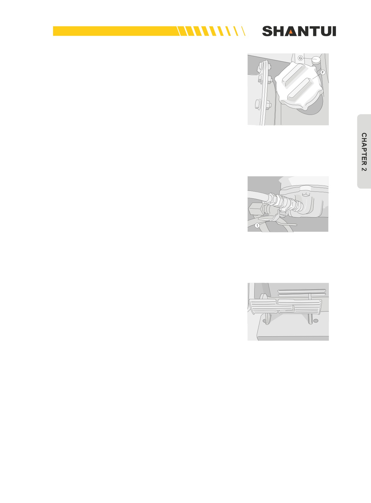
Check steering clutch case oil level (including transmis-
sion case and torque converter)
As shown in Figure 2-53, use dipstick (G) to check the oil lev-
el. If needed, oil should be added through the filter screen (F).
The lubricant type used depends on the ambient temperature.
See the “USE OF FUEL, COOLANT AND LUBRICANTS AC-
CORDING TO AMBIENT TEMPERATURE” for reference.
Figure 2-53
When checking oil level, stop the engine.
When operating on a slope of over 20 degree, the oil level
should be at the (H) HIGH level.
Drain the sediment in fuel tank (Figure 2-54): Turn loose the
valve (1) on the bottom of fuel tank, to drain the water and
sediment in the fuel.
Figure 2-54
Check brake pedal’s journey (Figure 2-55)
When the engine is running, the standard journey is 110-
130mm (operating force is 15kg). When the engine stops, the
stroke is about 75mm. If the pedal’s stroke is over 190mm,
the brake function is not adequate, and you should make ad-
justment following the “Adjustment” section.
Figure 2-55
59
OPERATION | OPERATION
2.4.2 OPERATION METHODS AND STEPS
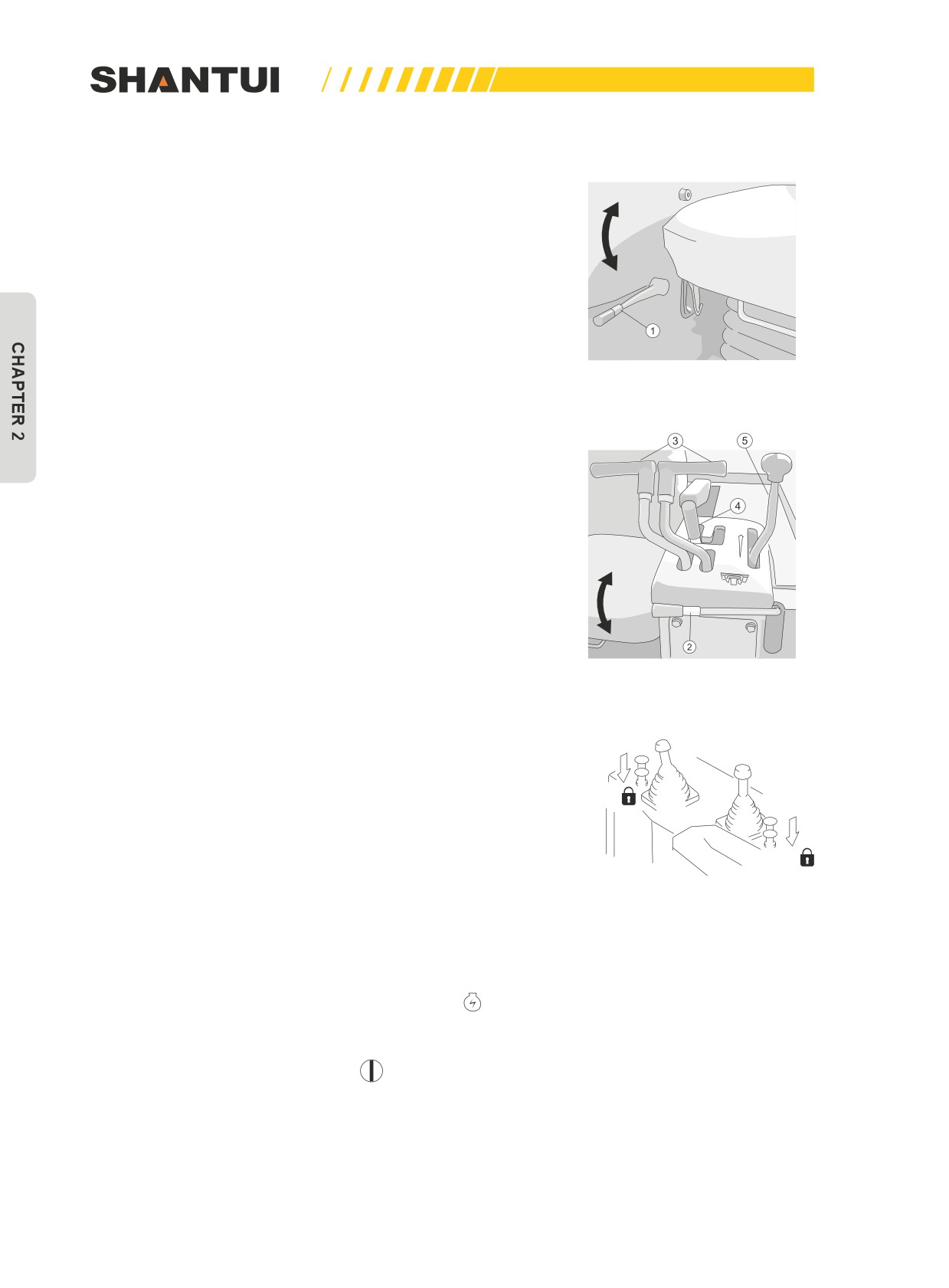
1. Check the positions of various control levers before start-
Lock
ing (Figures 2-56 and 2-57). (1)—Brake lock lever, (2)—
Gear shift lock lever, (3)—Steering control lever, (4)—Gear
shift lever, (5)—throttle gear shift lever. Adjust the opera-
Free
tor’s seat, so that the operator can completely step down
the brake pedal while leaning against the seat back.
2. Brake lock lever (1) is in the LOCK position, as shown in
Figure (2-56)
Figure 2-56
3. Gear shift lever (4) is in the NEUTRAL position, and gear
shift lock lever (2) is in the LOCK position (Figure 2-57).
Free
Lock
Figure 2-57
4. The blade and ripper should be lowered to the ground, and
their control lever lock button should be in the LOCK posi-
tion. (Figure 2-58)
Lock
Lock
Figure 2-58
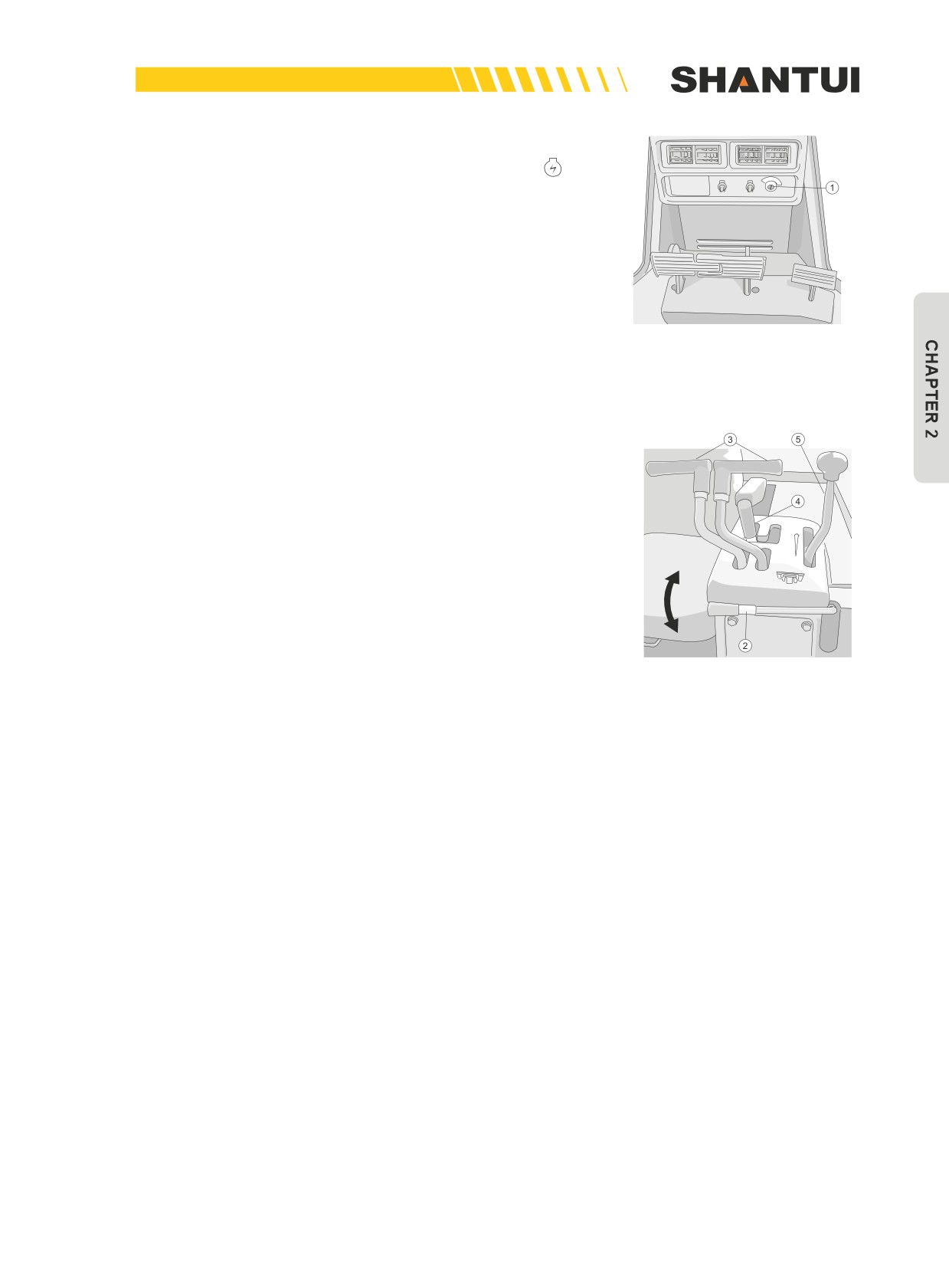
5. Starting engine
• Pull the throttle level (5) to the idling position. (Figure 2-57)
Turn the starting key (1) to the starting position . (Figure
2-59)
• When engine started, release the starting key (1), and the
key will automatically return to the
(ON) position. (Figure
2-59)
60
OPERATION | OPERATION
• If engine is not started, re-start it after 2min.
• The key should not stay in the “Starting” position
for
more than 10s.
• When the fuel is empty and you want to start the engine,
add sufficient fuel first and then let the fuel fill the core of
fuel filter and exhaust the air in the fuel system before start-
ing the engine again.
Figure 2-59
6.
Checks after starting engine
•
After starting the engine, perform the following checks:
•
Let the engine run at a low speed, until the engine oil pres-
sure is within the normal range.
•
Pull the throttle control lever (5) to let the engine idle at a
mid-range speed for about 5 min. (Figure 2-60)
•
Do not run the engine at low or high idle for more than 20
minutes. If it is necessary to run the engine at idling, apply
Free
a load from time to time or run the engine at a mid-range
speed.
•
After engine temperature is increased, check various me-
Lock
ters for abnormality.
•
Let the engine continue to run at a low-load, to let water
Figure 2-60
temperature rise. Water temperature between 74-91°C is
most ideal.
•
Check the color of exhaust for abnormalities, such as ab-
normal sound or vibration.
•
Do not suddenly accelerate the engine before the machine
reaches full operating temperature.
•
If engine oil pressure is not within the normal range, stop
the engine immediately, and check for reasons.
61
OPERATION | OPERATION
2.4.3 OPERATION WHEN MOVING
Before moving, check the safety around you.
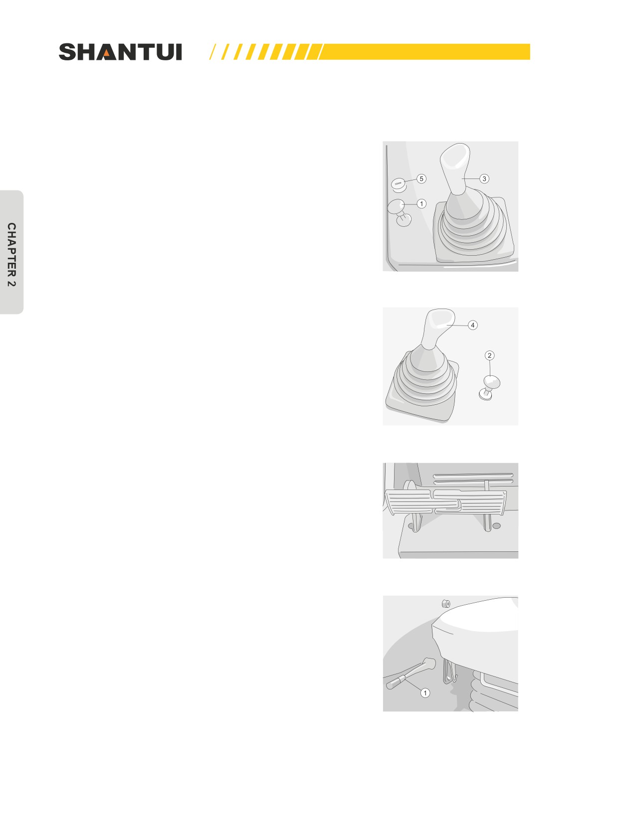
1. Release blade and ripper lock button (1) and (2) respec-
tively. (Figures 2-61 and 2-62)
2. Pull blade and ripper control lever (3) and (4), to raise
blade and ripper 40-50cm above ground. (Figures 2-61
and 2-62)
Figure 2-61
Figure 2-62
3. Step down the crossing part in the middle of the left and
right brake pedal, put the brake lock lever (1) to the FREE
position, and then release the brake pedal. (Figures 2-63
and 2-64)
Figure 2-63
Figure 2-64
62
OPERATION | OPERATION
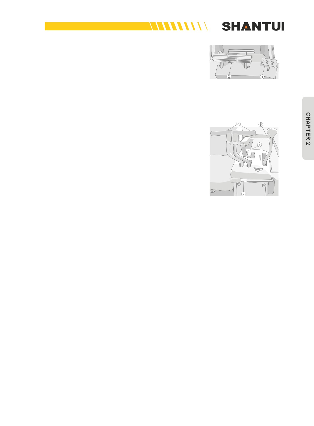
4. Release the gear shift lock lever (2) (Figure 2-57)
• Step down the deceleration pedal (1) to reduce engine
speed, so that there is no impact when the vehicle is start-
ed (Figure 2-65).
Figure 2-65
• Put the gear shift lever (4) to the needed position, and the
vehicle will start to move (Figure 2-66)
5. Pull throttle control lever (5), to accelerate the engine (Fig-
ure 2-66)
6. Through the gear shift lever (4) you can select any speed
without stopping the vehicle. (Figure 2-66)
• Forward←→Reverse
• After reducing vehicle speed, change Forward←→Reverse.
This can preventing impacting vehicle. Step down the de-
celeration pedal, to reduce engine speed, bring the gear
shift lever to the needed Forward or Reverse gear, and then
Figure 2-66
release the deceleration pedal, to accelerate the engine.
63
OPERATION | OPERATION
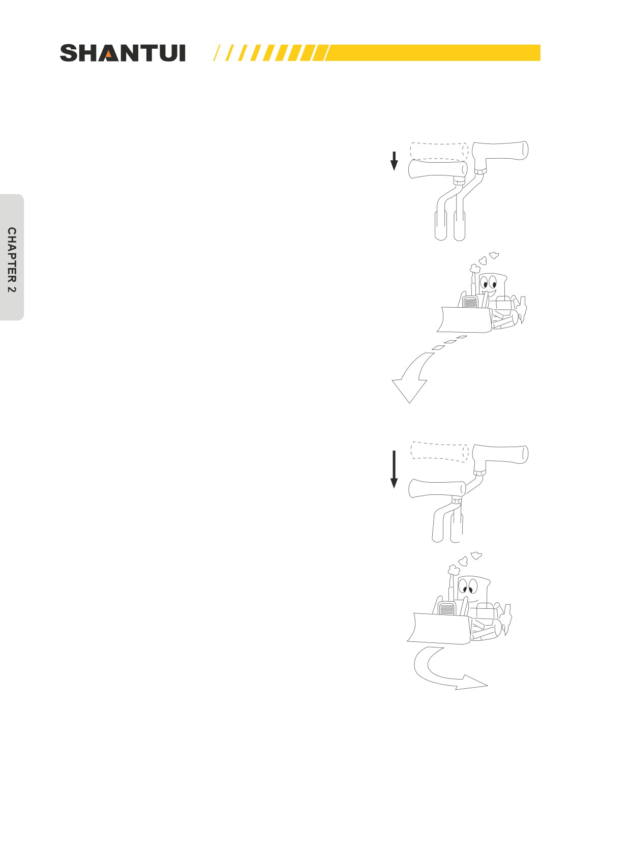
2.4.4 TURNING
Make a big turn to the left (right):
Pull left (right) steering lever half way, and the vehicle will
make a big turn to the left (right) (Figures 2-67);
Figure 2-67
Make a small turn to the left (right):
Pull the left (right) steering lever to the bottom, the left (right)
steering clutch will detach, the brake will be activated, and the
vehicle will make a small turn to left (right). (Figure 2-68)
Figure 2-68
64
OPERATION | OPERATION
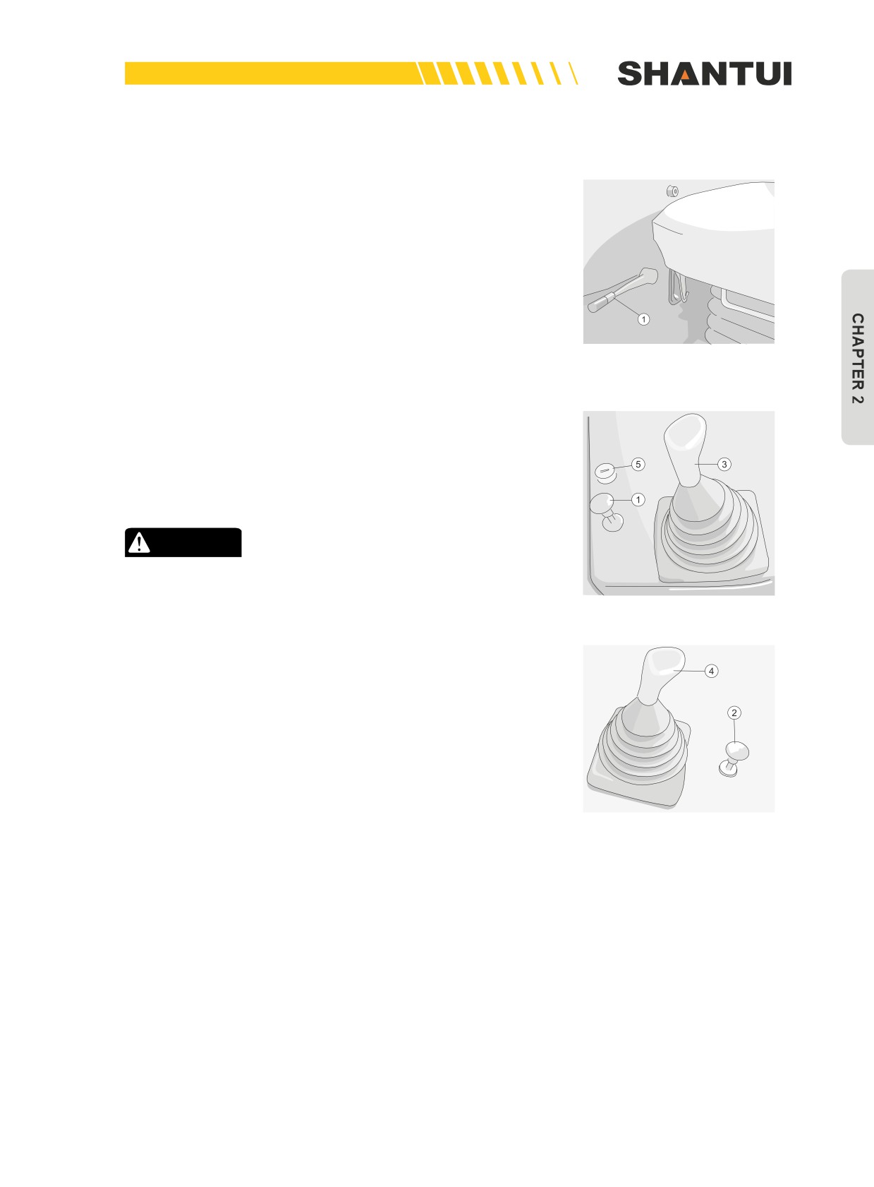
2.4.5 PARKING
Push the throttle control lever (5) to the idling position, to re-
duce engine speed. Push the gear shift lever (4) to the NEU-
TRAL (N) position. (Figure 2-66)
Step down the crossing part in the middle of the left and right
brake pedal (2), and the vehicle stops (Figure 2-65); pull the
brake lock lever (1) to the LOCK position (Figure 2-69), to lock
the gear shift lock lever (2) (Figure 2-66).
Figure 2-69
Push the blade control lever (3) and ripper control lever (4)
to the Lowering position, to lower the blade and ripper to the
ground. And then press the blade control lever’s lock button (1)
and ripper control lever’s lock button (2). (Figure 2-70, 2-71)
CAUTION
Park the vehicle on a firm and level ground as far as pos-
sible, and avoid parking it in a dangerous place.
Figure 2-70
Figure 2-71
65
OPERATION | OPERATION
2.4.6 STOPPING ENGINE
Let the engine idle for 5min, to cool it down. Turn the key to the
(OFF) position, and the engine
will stop running. Pull out the key. If you suddenly stop the vehicle when the engine is not cooled, it
will dramatically shorten the lifecycle of the engine. Never suddenly stop the vehicle unless in emer-
gency.
2.4.7 OPERATION IN SPECIAL CLIMATE CONDITIONS
Precautions for low temperature:
1. If the temperature is too low, it will be difficult to start the engine, and the cooling water will be
frozen, causing negative impacts on the vehicle, so you should take appropriate measures, and
select oil and water according to the “USE OF FUEL, COOLANT AND LUBRICANTS ACCORD-
ING TO AMBIENT TEMPERATURE”.
2. When the atmospheric temperature is lower than 0°C, to prevent the cooling water from freez-
ing, you can use the antifreeze based on the lowest temperature. For the mixing proportion and
usage methods of water and antifreeze, see “CLEAN INSIDE OF COOLING SYSTEM”.
3. Before adding the mixed antifreeze, thoroughly clean the cooling system.
4. When the weather becomes warm, drain the antifreeze (except for the permanent antifreeze),
and clean the cooling system, before replacing the clean water.
5. Be sure to clean the snow or water on the hydraulic oil cylinder’s piston rod. If they freeze into
ice, they will damage the oil cylinder’s oil seal.
CAUTION
• Water without antifreeze should be thoroughly drained during the nighttime of winter, to
prevent the parts from being cracked by freezing. Note: Do not drain water in areas such
as oil cooler.
• Use standard antifreeze. Never use methanol or ethanol based antifreeze, as it may cause
malfunction of engine.
• Antifreeze is flammable, so be careful of fire.
• When the ambient temperature drops, the capacity of the battery will also drop. If the bat-
tery charge ratio is low, the battery electrolyte may freeze. Maintain the battery charge as
close as possible to 100%, and insulate it against cold temperature so that the machine
can be started easily the next morning.
66
OPERATION | OPERATION
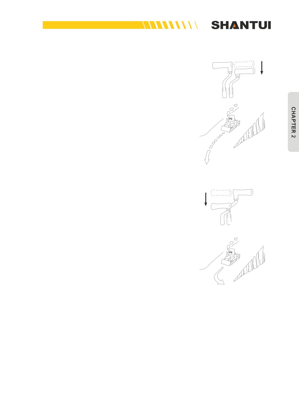
2.4.8 OPERATING ON SLOPES
Make a big turn to left (right) :
When going down a slope (Figure 2-72). Pull the right (left)
steering control lever half way, and the vehicle will make a big
turn to left (right).
Figure 2-72
Make a small turn to left (right):
When going down a slope (Figure 2-73). Pull left (right) steer-
ing control lever to the bottom, and the vehicle will turn to left
(right).
Figure 2-73
67
OPERATION | OPERATION
2.4.9 PRECAUTIONS
1. Do not park vehicle on a slope unless in special situations.
• If you do need to park the vehicle on a slope, face the head of vehicle downhill, and lock the
brake pedal. When the slope is big, you can slightly cut the blade into the ground, to prevent ve-
hicle from slipping.
2. When the vehicle travels on a slope, the longitudinal slope should not be over 30 degree, and
when going uphill, do not travel backward.
3. When you start the vehicle on a slope, step down the left-right brake pedal first, and then pull
the gear shift lever to Gear 1, while slowly releasing the brake pedal. If the engine speed is too
fast, you can use the brake pedal to reduce speed.
4. When going downhill, pull the gear shift lever to a low-speed gear, and use the engine to brake.
5. When operating machine on sloped areas of more than 20°, fill all appropriate components with
oil to H level.
CAUTION
• Always travel straight up or down a slope. Traveling at an angle or across the slope is ex-
tremely dangerous.
• Do not shift gear or cross obstacles on a slope.
• If the fuel level in the fuel tank becomes low when working on slopes, the engine may suck
in air because of the angle of the machine or the swaying of the machine. If this makes the
engine stop, the braking effect will be reduced, so be careful not to let the fuel level in the
fuel tank become too low.
68
OPERATION | OPERATION
2.4.10 OPERATING IN WATER
When the vehicle is travelling in water, check out water depth
and the soil under water first, to avoid accidents because the
water is too deep and the soil sinks from carrying the load.
Water level should not exceed the center of the idler (Figure
2-74).
When operating in sea water or other corrosive water, wash
the vehicle with clean water after completion.
Figure 2-74
2.4.11 OPERATING ON DESERT
When operating on desert or other types of dusty ground,
try to keep the vehicle sealed off from the outside world, and
clean the air cleaner at any time.
69
DOZING OPERATION | OPERATION
2.5 DOZING OPERATION
Reasonably choosing the models as well as the adjustment
and operation methods of the blade according to the dozing
objects is very important to extending the lifecycle of the ve-
hicle, reducing the operator’s fatigue, and increasing produc-
tivity.
The SD22 bulldozer is suitable for the general operating con-
ditions. The SD22E bulldozer is suitable for loose soil. The
SD22S is suitable for operating in swamps.
There are three types of blades: the “straight tilt blade”, the
“angle blade”, and the “U-Blade”. They are suitable for differ-
ent terrains and operation objects.
The effective dozing distance is 70m at the maximum. For
long-distance application, using a fork lift is more economical.
2.5.1 OPERATION OF BLADE AND RIPPER
The control levers and buttons of the work equipments. See
“The Roles of Various Controls” (See 2-1-2)
2.5.2 BLADE ADJUSTMENT
Angle blade adjustment
1. Adjustment of angle blade’s turning angle
►►
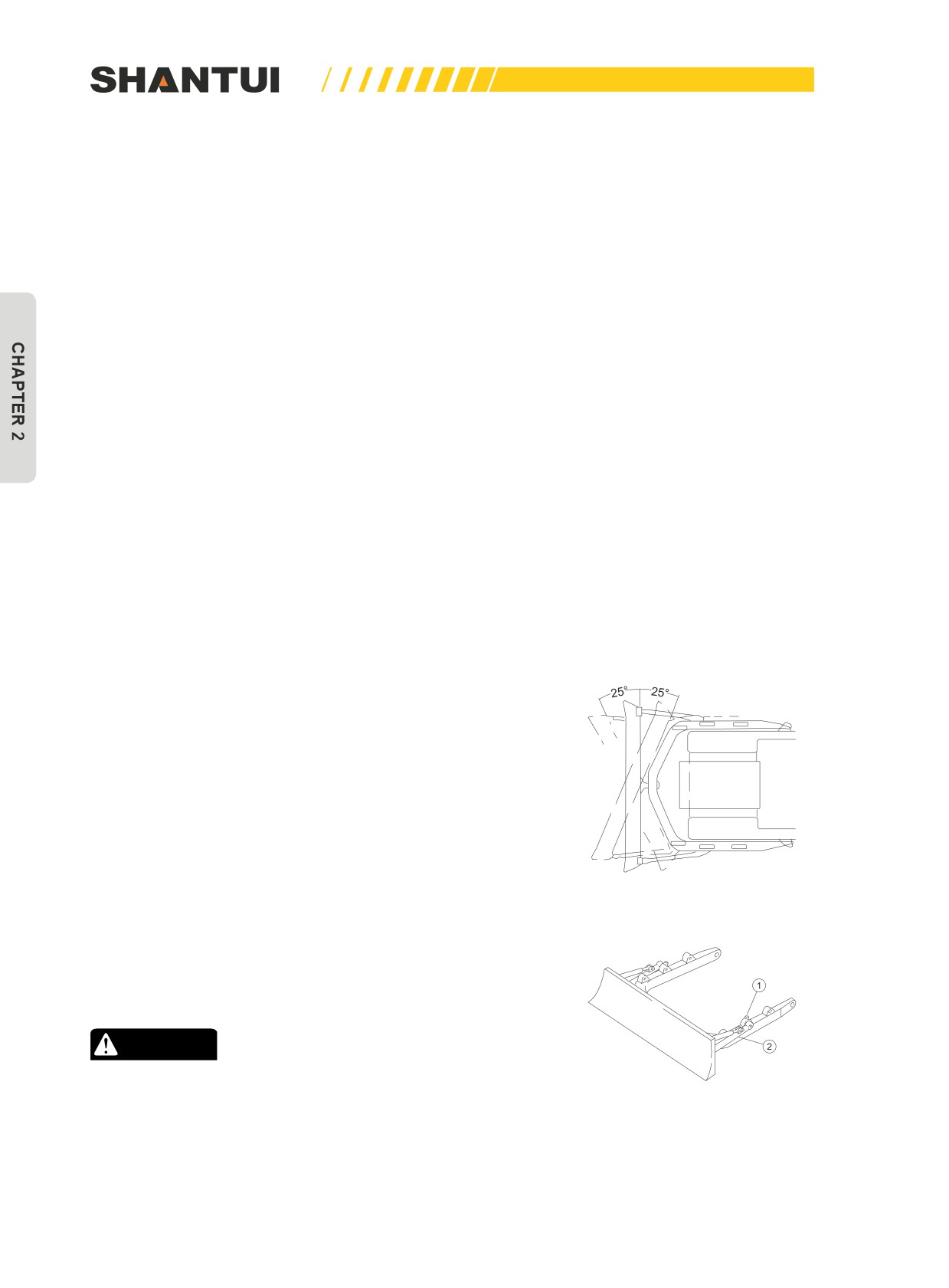
The two sides of the blade can be adjusted to be 25º. (Fig-
ure 2-75)
• Raise the blade to be 400-500mm above ground, and put a
block under the C-Frame.
• Pull out the pins (1) on both sides to remove the push rod’s
Figure 2-75
arm (2) from the C-Frame (Figure 2-76)
• After putting the blade into an angle, install the push rod’s
arm (2) to the needed position. (the push rod frame has
three supports on each side), and then insert the pin (1).
CAUTION
After removing push rod’s arm, be careful that the blade
will swing freely.
Figure 2-76
70
OPERATION | DOZING OPERATION
2. Adjust of angle blade’s tilt
►►
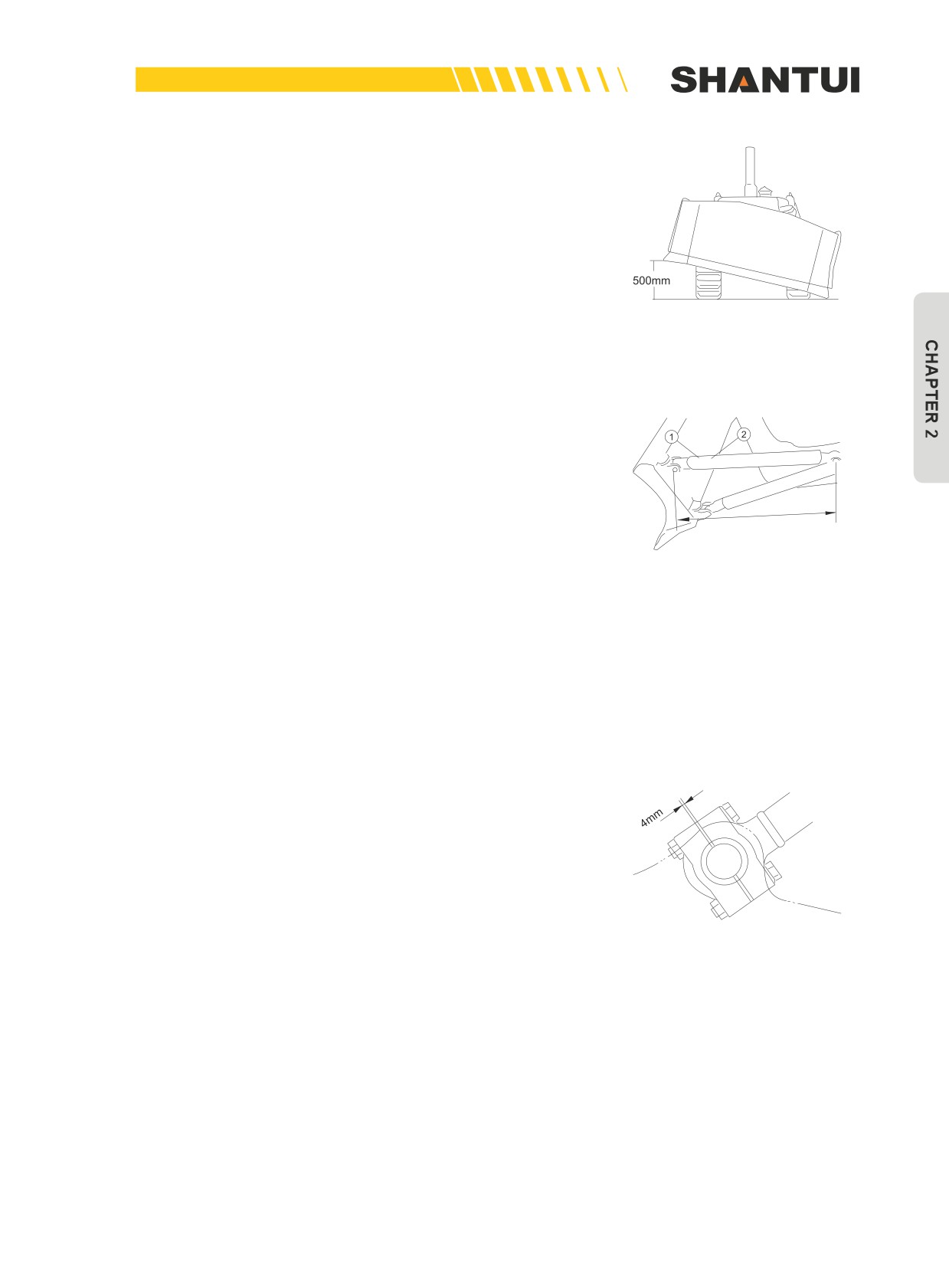
The biggest tilt of blade: 500mm (Figure 2-77)
a. Raise the blade to be 400-500mm above ground, and put a
block under the C-Frame.
Figure 2-77
b. Loosen jack bolt (1), insert an iron bar into the hole of the
support rod (2) to rotate the support rods on the two sides, to
elongate and shorten them respectively. Tilt the blade to the
required height, and then tighten jack bolt. (Figure 2-78)
• L, the length of the support rod (Figure 2-78), is generally
L
1338mm, and the blade’s tilt should be within 500mm.
• Do not attempt to tilt the blade to more than 500mm, to pre-
vent unwanted effect.
Figure 2-78
►►
When using the adjusting rod to turn the support arm, the
blade should be above ground before tilting it.
c. Adjustment of gaskets
• The standard thickness of the adjustment gaskets between
the blade lift cylinder’s piston rod and cap is 4mm (Figure
2-79).
• Remove some gaskets, to adjust the spherical clearance
between oil cylinder’s piston rod and cap. The suitable
clearance maintained with gaskets is 0.2~0.6mm.
Figure 2-79
71