Shantui SD22. Operation and Maintenance Manual - 1
FOREWARD
REMINDERS
TRAINING
If you are a novice, please receive training by Shantui or its agent before operating the ma-
chine to ensure the safety of you and others.
SAFETY
Before operating the machine, please read this Operation and Maintenance Manual thor-
oughly first and ensure you can skillfully operate it. See Chapter 1 for details about the safety
precautions.
INSPECTION
Before operating the vehicle, please check out the vehicle’s conditions, climate conditions,
and your surroundings. You can only operate the machine when all these conditions meet the
requirements.
CAUTION
Please properly use the machine in accordance with the conditions of the construction site.
I
FOREWARD
FOREWARD
The SD22 Series Bulldozers are the hydraulically transmitted bulldozers with a rated power of
162kw (220HP). Among them, SD22 is the standard machine, suitable for general earthwork opera-
tion; SD22C is for a coal handling machine with an air-conditioned driver’s cab suitable for construc-
tion operation dealing with loose materials such as in power plants and harbors; SD22D is the des-
ert model, suitable for earthwork operation on deserts and wilderness; SD22E is a crawler bulldozer
with an extended length, suitable for general earthwork operation with a lower ground pressure;
SD22S is the machine for wetter conditions, suitable for construction operation in areas with soft
soil, wetland and swamp; and SD22R is designed for environmental protection purposes, suitable
for burying, leveling and compacting landfills.
This manual provides detailed descriptions of the structures, performances, driving operation, main-
tenance, troubleshooting, as well as transportation and storage of the bulldozers in this series. It
provides the basic knowledge for management personnel and operators to use the equipment effi-
ciently, economically and properly.
This manual provides the rules and guidelines which will help you use this machine safely and effec-
tively. The precautions in this manual must be followed at all times when performing operation and
maintenance.
WARNING
Operators and maintenance personnel must always do as follows before beginning operation
or maintenance:
• Always be sure to read and understand this manual thoroughly before performing opera-
tion and maintenance.
• Read the safety messages given in this manual and the safety labels affixed to the ma-
chine thoroughly and be sure that you understand them fully.
• Keep this manual at the given storage location for the Operation and Maintenance Manual,
and have all personnel read it periodically.
• If this manual has been lost or has become dirty and cannot be read, request a replace-
ment manual immediately from Shantui or your Shantui distributor.
If you sell the machine, be sure to give this manual to the new owners together with the machine.
II

FOREWARD
LOCATION TO KEEP THE OPERATION & MAINTENANCE MANUAL:
As shown in the figure on the right, the Operation & Mainte-
nance Manual is generally put in the magazine pockets on the
right and left cab doors.
For the use, maintenance and troubleshooting of engine, apart
from this manual, please also refer to the engine’s operation
manual for details.
All the areas regarding the safety of people and machine as
well as all the important technical requirements in this manual
are marked with or►►Please firmly remember them.
ABOUT THE WARRANTY
The warranty only covers faults caused by material or manufacturing defects, excluding other faults.
Shantui is not responsible for faults or damages caused by improper use or omission, including but
not limited to damages caused by operation without sufficient coolant or lubricant; excessive supply
of fuel; operation above the speed limit; lack of maintenance to the cooling and lubricating systems;
improper storage, start, warm-up, break-in or stop operation; unauthorized repairing of the engine;
using fuels or lubricants that are not recommended for the machine or using fuels or lubricants
mixed with dirty substances such as water or mud.
For faults that are really caused by material or manufacturing defects, Shantui is not responsible for
collateral costs as well as all the business expenses and losses caused by the repair work.
III
FOREWARD
BREAKING IN THE NEW MACHINE
Your Shantui machine has been thoroughly adjusted and tested before shipment. However, operat-
ing the machine under severe conditions at the beginning can adversely affect the performance and
shorten the machine life.
Be sure to break-in the machine for the initial 100 hours.
During break-in operations, follow the precautions described below:
1. Check before starting;
2. Start the engine and let it run at idling for 5min, to let the temperature rise normally, and let the
machine enter the working condition;
3. Avoid heavy-duty or high-speed operation;
4. Do not start the engine in a rush, do not accelerate sharply, and do not make an emergency
brake or a sharp turn;
5. Watch the machine and make adjustment at any time, to keep the machine in the normal condi-
tion;
6. After using the machine for 250 hours, performance maintenance according to the initial 250
hours service table and the items listed below.
►►
The initial 250 hours service table.
►►
The operation hours will be indicated by the hour meter.
►►
When replacing the fuel filter, check if there is dirty stuff in it. If it is severely clogged, try to find
out the reasons before replacement if possible.
The disassembly and repair of the track tension must be performed under the guidance
of the after-sales service personnel of Shantui (or its distributor), or damage may be caused
to the track tension, resulting in danger!
IV
FOREWARD
SAFETY LABELS AND WORDS
Safety labels are affixed to the machine to inform the operator or maintenance worker on the spot
when carrying out operation or maintenance of the machine that may involve hazard.
The following signal words are used to inform you that there is a potential hazardous situation that
may lead to personal injury or damage. In this manual and on machine labels, the following signal
words are used to express the potential level of hazard.
Indicates an imminently hazardous situation which, if not avoided, will re-
DANGER
sult in death or serious injury.
Indicates a potentially hazardous situation which, if not avoided, could re-
WARNING
sult in death or serious injury.
Indicates a potentially hazardous situation which, if not avoided, may re-
CAUTION
sult in minor or moderate injury.
Example of safety label using words:
WARNING
When standing up from the operator's seat, always place the safety lock lever in the LOCK
position. If you accidentally touch the control levers when they are not locked, this may
cause a serious injury or death.
V
CONTENTS
CONTENTS
CHAPTER 1: SAFETY
1
1.1 SAFETY LABELS
1
1.1.1 POSITIONS OF SAFETY PICTOGRAMS
2
1.1.2 SAFETY LABELS
3
1.2 SAFETY RULES
7
1.2.1 SAFETY PRINCIPLES
7
1.2.2 SAFETY FEATURES
7
1.2.3 CLOTHING AND PERSONAL PROTECTIVE ITEMS
8
1.2.4 UNAUTHORIZED MODIFICATION
8
1.2.5 ALWAYS APPLY LOCK WHEN LEAVING OPERATOR'S SEAT
8
1.2.6 GETING ON OR OFF THE MACHINE
9
1.2.7 FIRE CAUSED BY FUEL OR OIL
9
1.2.8 PREVENTION OF BURNS
10
1.2.9 BE CAREFUL ABOUT ASBESTOS DUST
10
1.2.10 PREVENTING INJURY FROM SQUEEZING OR CUTTING
10
1.2.11 PRECAUTIONS WHEN USING ROPS (ROLL OVER PROTECTIVE STRUCTURE, IF
ROPS ARE INSTALLED)
11
1.2.12 PRECAUTIONS FOR OPTIONAL ATTACHMENTS
11
1.3
SAFETY PROCEDURES
12
1.3.1 BEFORE STARTING ENGINE
12
1.3.2 OPERATION
13
1.3.3 TRANSPORTATION
16
1.3.4 BATTERY
17
1.3.5 TOWING
18
1.3.6 BEFORE CARRYING OUT MAINTENANCE
19
1.3.7 DURING MAINTENANCE
20
CHAPTER 2: OPERATION
25
2.1 CONTROLS
25
2.1.1 GENERAL VIEW OF CONTROLS
25
2.1.2 ROLES OF VARIOUS CONTROLS
26
2.1.3 OTHER DEVICES
31
2.2 THE ELECTRIC SYSTEM (WITHOUT GPS)
37
2.3 THE ELECTRIC SYSTEM (WITH GPS)
39
2.3.1 PRECAUTIONS FOR TURNING ON AND OFF THE MAIN MACHINE
41
2.3.2 THE ENVIRONMENTAL REQUIREMENTS OF THE CONTROLLERS AND MONI-
TORS
42
2.3.3 DESCRIPTION OF THE MONITOR PANEL
42
VI
CONTENTS
2.3.4 DESCRIPTION OF THE SWITCH BUTTON PANEL
43
2.3.5 OPERATION OF THE ELECTRIC SYSTEM
44
2.3.6 OPERATION OF THE HORN BUTTON
52
2.3.7 PRECAUTIONS FOR FUSE BOX
53
2.3.8 IN-LINE FUSE
54
2.3.9 POWER SOCKETS
54
2.3.10 WARM-UP AND START
54
2.3.11 CAB’S HEAD LAMP SWITCH
55
2.3.12 WINDSHIELD WIPER SWITCH
55
2.3.13 DESCRIPTION OF THE BOND STRAPS OF CONSTRUCTION MACHINERY’S
ELECTRIC SYSTEM
56
2.4
OPERATION
57
2.4.1 CHECK BEFORE STARTING ENGINE
57
2.4.2 OPERATION METHODS AND STEPS
60
2.4.3 OPERATION WHEN MOVING
62
2.4.4 TURNING
64
2.4.5 PARKING
65
2.4.6 STOPPING ENGINE
66
2.4.7 OPERATION IN SPECIAL CLIMATE CONDITIONS
66
2.4.8 OPERATING ON SLOPES
67
2.4.9 PRECAUTIONS
68
2.4.10 OPERATING IN WATER
69
2.4.11 OPERATING ON DESERT
69
2.5
DOZING OPERATION
70
2.5.1 OPERATION OF BLADE AND RIPPER
70
2.5.2 BLADE ADJUSTMENT
70
2.5.3 DOZING OPERATION
73
2.5.4 LEVELING OPERATION
73
2.5.5 DOZING SIDEWAYS
73
2.5.6 METHODS FOR EXTENDING MACHINE LIFE
74
2.6
TOWING, LIFTING, TRANSPORTATION AND STORAGE
75
2.6.1 TOWING
75
2.6.2 LIFTING
75
2.6.3 TRANSPORTATION
76
2.6.4 STORAGE
77
CHAPTER 3: STRUCTURE AND PRINCIPLE
79
3.1 MACHINE STRUCTURE AND MAIN PARAMETERS
79
3.1.1 MACHINE APPEARANCE
79
3.1.2 SPECIFICATIONS AND TECHNICAL PARAMETERS
80
3.2 ENGINE
86
VII
CONTENTS
3.2.1 ENGINE APPEARANCE
86
3.2.2 ENGINE’S MAIN PERFORMANCE INDICATORS
88
3.2.3 POWER OUTPUT DEVICES
89
3.2.4 RADIATOR ASSEMBLY
91
3.2.5 FUEL TANK AND PIPING
93
3.2.6 ENGINE OPERATION
94
3.2.7 HYDRAULIC TORQUE CONVERTER
95
3.3
UNIVERSAL JOINT
97
3.4
TRANSMISSION CASE
98
3.4.1 PLANETARY GEAR MECHANISM’S PRINCIPLE AND CLUTCH MECHANISM
100
3.4.2 THE POWER TRANSMISSION ROUTE OF THE VARIOUS GEARS OF THE TRANS-
MISSION CASE
104
3.5
CENTRAL DRIVE
106
3.6
STEERING CLUTCH
109
3.7
STEERING BRAKE
110
3.7.1 WORKING PRINCIPLE
111
3.7.2 SERVO MOTOR VALVE’S WORKING PRINCIPLE
111
3.8
FINAL DRIVE
112
3.9
DRIVE SYSTEM'S OPERATION
114
3.9.1 GEAR SHIFT
114
3.9.2 STEERING
115
3.10
WALKING MECHANISM
116
3.10.1 TRACK TENSION DEVICE
117
3.10.2 IDLER
118
3.10.3 TRACK ROLLER
119
3.10.4 CARRIER ROLLER
120
3.10.5 TRACK
121
3.10.6 EQUALIZER BAR
123
3.11
HYDRAULIC SYSTEM
124
3.11.1 WORK EQUIPMENT’S HYDRAULIC SYSTEM
124
3.11.2 GEARSHIFT AND STEERING HYDRAULIC SYSTEM
136
3.12
WORK EQUIPMENT
144
3.12.1 STRAIGHT TILT BLADE
144
3.12.2 U-BLADE
144
3.12.3 ANGLE BLADE
146
3.12.4 RIPPER
147
3.13
ELECTRIC SYSTEM
148
3.13.1 DESCRIPTION OF THE ELECTRIC SYSTEM
148
3.13.2 ELECTRIC WIRING CHART
148
3.13.3 WIRE CODES
149
VIII
CONTENTS
3.13.4 ELECTRIC PRINCIPLE DIAGRAM
150
CHAPTER 4: MAINTENANCE
153
4.1
MAINTENANCE
153
4.1.1 SERVICE TABLE
155
4.1.2 INITIAL 250 HOURS SERVICE
157
4.1.3 EVERY 250 HOURS SERVICE
157
4.1.4 EVERY 500 HOURS SERVICE
163
4.1.5 EVERY 1000 HOURS SERVICE
164
4.1.6 EVERY 2000 HOURS SERVICE
167
4.1.7 EVERY 4000 HOURS SERVICE
167
4.1.8 MAINTENCE WHEN NEEDED
168
4.1.9 LUBRICATION DIAGRAM AND LUBRICATION TABLE
174
4.1.10 ADJUSTMENT OF VARIOUS PARTS
176
4.1.11 SERVICE STANDARDS FOR MAIN PARTS
180
4.1.12 STANDARD TIGHTENING TORQUES FOR BOLTS AND NUTS
211
4.2
TROUBLESHOOTING
213
4.2.1 ENGINE
213
4.2.2 ELECTRIC SYSTEM
214
4.2.3 CHASSIS
214
4.3
PRECAUTIONS FOR DISASSEMBLY AND ASSEMBLY
215
4.3.1 DISASSEMBLY
215
4.3.2 ASSEMBLY
216
4.3.3 ASSEMBLY AND DISASSEMBLY OF BEARINGS
216
4.3.4 OIL SEAL INSTALLATION
217
4.4
ADDITIONAL TABLE: USE OF FUEL, COOLANT AND LUBRICANTS ACCORDING
TO AMBIENT TEMPERATURE
218
IX
SAFETY | SAFETY LABELS
CHAPTER 1: SAFETY
1.1 SAFETY LABELS
The following warning signs and safety labels are used on this machine.
• Be sure that you fully understand the correct position and content of labels.
• To ensure that the content of labels can be read properly, be sure that they are in the correct
place and always keep them clean. When cleaning them, do not use organic solvents or gaso-
line. These may cause the labels to peel off.
• There are also other labels in addition to the warning signs and safety labels. Handle those labels
in the same way.
• If the labels are damaged, lost, or cannot be read properly, replace them with new ones. For de-
tails of the part numbers for the labels, see this manual or the actual label, and place an order
with Shantui distributor.
1
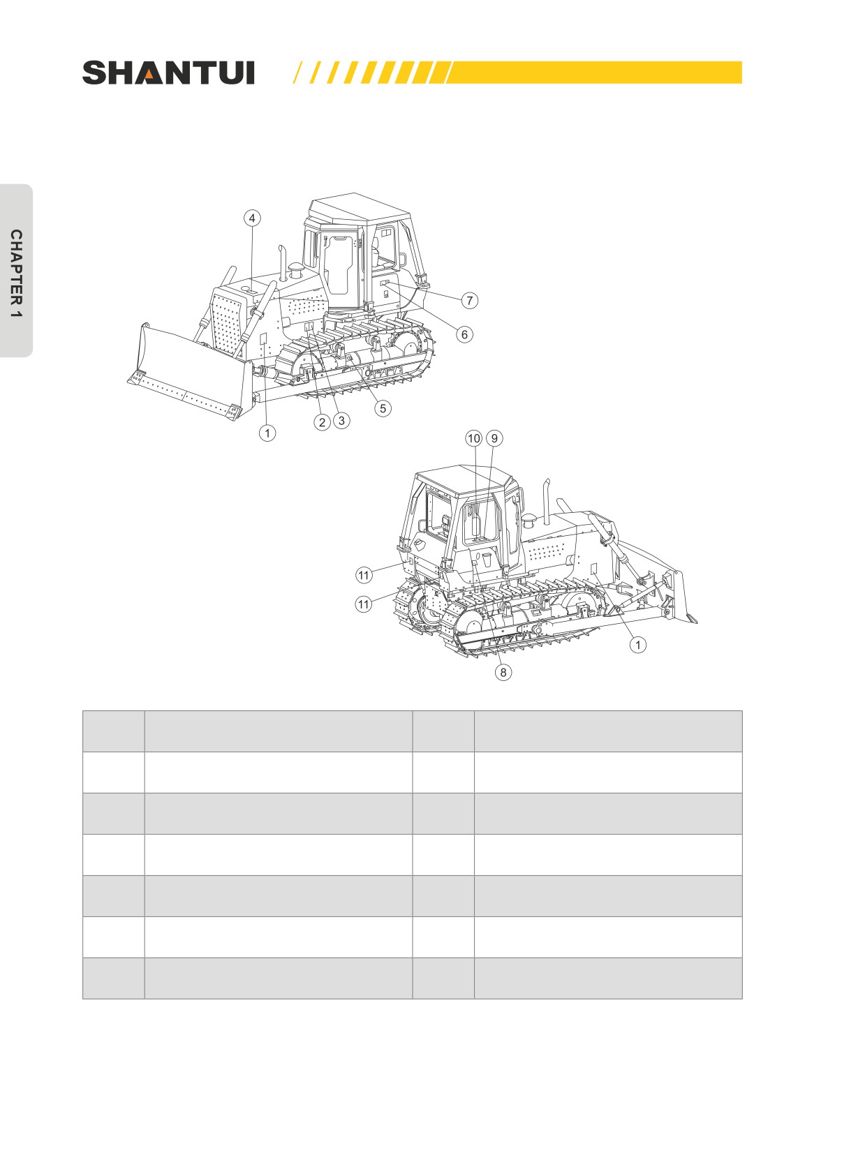
SAFETY LABELS | SAFETY
1.1.1 POSITIONS OF SAFETY PICTOGRAMS
No.
Name
No.
Name
1
Signs (Caution: Approaching)
7
Signs (battery cable)
2
Caution: Engine is running
8
Safety and use of working oil tank
3
Sign (Caution: High temperature)
9
Caution signs
4
Signs for radiator
10
Sign (Warning: Backing)
5
Caution sign for track adjustment
11
Warning signs
6
Signs (battery)
2
SAFETY | SAFETY LABELS
1.1.2 SAFETY LABELS
1. Precautions for operation, inspection, Leaving operator's seat and maintenance (09967-
00200)
CAUTION
1. Read this manual carefully before operating
6. When you want to stop the engine, let it idle
the machine.
for 5min and then turn the key switch to the
2. Before starting the engine, check if the wa-
“OFF” position.
ter tank is full of cold water; and when the
7. Precautions for traveling on slopes
temperature is below 0°C, drain water or
(1)Make sure if the brake is reliable.
add coolant in a timely manner.
(2)The fuel should be added to the required
3. Before operating the machine each day,
level.
check if various oil levels meet the require-
(3)Don’t step on the deceleration pedal when
ments, and drain the water from the fuel
going up a slope (see the manual).
tank completely.
8. Check the engine and the parts that are
4. When starting or stopping the machine or
easy to catch fire frequently, and clear flam-
leaving the operator’s seat, follow the rules
mable materials (e.g. twigs and leaves) ac-
below:
cumulated, to avoid hampering operation
(1)Put the gear shift lever in the NEUTRAL po-
and catching fire.
sition. If there is a safety mechanism, lock it
9. Precautions for repair and maintenance:
with the safety lock lever.
(1)Park the bulldozer on a level ground.
(2)Lock the brake.
(2)When lowering the work equipment to the
(3)When lowering the work equipment to the
ground, set the work equipment’s control
ground, set the work equipment’s control
lever to the LOCK position.
lever to the LOCK position.
(3)When the bulldozer is jacked up by the
5. When the engine is running, follow the rules
work equipment, don’t go under the ma-
below:
chine.
(1)Don’t open the engine’s side cover.
10. See the manual for lubrication points and
(2)Don’t get close to the fan or the fan’s belt.
lubrication cycles.
(3)Make sure if the brake is reliable.
09967 - 00200
2. Precautions when traveling in reverse(09802-02000)
WARNING
To prevents SEVERE INJULY or DEATH, do
the following before moving machine or its
attachments:
• Honk horn to alert people nearby.
• Be sure no one is on or near machine.
• Use apotter if view is obstructed.
Follow above even if machine equipped with
back-up alarm and mirrors.
09802- 02000
3
SAFETY LABELS | SAFETY
3. Precautions for high-temperature cooling water (09966-00200)
WARNING
When the water temper-
1.
Before operating the machine each
ature is high, don’t turn
day, check the cooling water from the
water injection port, to let the water
off the radiator cap, to
level be above the filter (screen.
prevent the hot water
2.
After changing or adding cooling wa-
from spurting out due
ter, let the engine run idle for 5-10min
before operating the machine, to
to internal pressure.
let the water fill the entire cooling
system, and then make sure that the
water level is indeed above the filter
screen at the water injection port be-
fore beginning operation.
3.
When injecting water or injecting
coolant, never remove the filter
screen.
4. Precautions for high-temperature hydraulic oil (09965-02100)
CAUTION
• When opening the cap, must stop the engine first.
• When the oil temperature is high, don’t open the cap. to prevent the
hot oil from spurting out.
• Slowly turn loose the cap of the oil tank, to completely release the
internal pressure.
• When the oil temperature is high, don’t open the oil drain plug.
• The oil in the hydraulic tank and the filter element of the filter
should be changed after the first 250 hours, and after that, should
be changed every 1000 hours. (See the manual for the replacement
requirements.)
• When replacing the filter element, lower the work equipment to the
ground, and stop the engine from running.
09665 - 02100
5. Caution for hot surface of engine (09817-00880)
•
This label indicates that touching hot parts such as
a running engine, motor or muffler or one that has
just run may have the risk of being scalded. Do not
touch them at a high temperature.
09817- 00880
4
SAFETY | SAFETY LABELS
6. Precautions for check and adjust track tension (09657-02100 is near or in the inner side of
the track adjustment cover)
CAUTION
• When increasing track tension, inject
Cap
grease from the grease fitting.
• When decreasing track tension, turn
loose the screw plug by one turn and
squeeze the grease out. (See the manu-
al for details about the adjustment steps
of track.)
• The screw plug should not be loosened
Grease fitting
by more than one turn. Never loosen
any parts other than the screw plug, to
prevent the internal high-pressure oil
from spurting out to cause accidents.
• After the adjustment, tighten the screw
plug.
09657 - 02100
7. Precautions for handling battery cables (09808-02000)
WARNING
Improper use of the booster cable and
the battery cable may cause explosion,
leading to serious personal injury or
even death.
•Use the booster cable and the battery
cable according to the specifications
in the manual.
09808- 02000
8. Caution for engine running (09667-10880)
09607- 10880
5
SAFETY LABELS | SAFETY
9. Caution for approach when machine moving (09806-10880)
09806- 10880
10. Precautions for handling accumulator (09664-02000)
WARNING
Explosive gases
Cigarettes, flames and sparks may cause the battery
to explode. Take precautions to protect your eyes and
face from being hurt by battery. People without proper
guidance and training shall not charge the battery or
use the booster cable or adjustment cable to connect
the battery.
Keep the breather tightened and level
Toxic gases may cause serious burning.
The material contains sulphuric acid. Prevent it from
contacting skin, eye or clothes. In case of an ac-
cident, wash with clear water immediately and seek
medical care.
Put in places not accessible by children
09664- 02000
6
SAFETY | SAFETY RULES
1.2 SAFETY RULES
1.2.1 SAFETY PRINCIPLES
• Only trained and authorized personnel can operate and maintain the machine. If you are under
the influence of alcohol or medication, your ability to safely operate or repair your machine may
be severely impaired putting yourself and everyone else on your jobsite in danger.
• Follow all safety rules, precautions and instructions when operating or performing maintenance
on the machine.
• When working with another operator or with a person on worksite traffic duty, be sure that all per-
sonnel understand all hand signals that are to be used.
• If you find any abnormality in the machine during operation or maintenance, stop the machine im-
mediately and check it out. Do not operate the machine until the abnormality has been corrected.
• Follow all the requirements.
• This machine is suitable for use below 3000 meters above sea level. With the increase of alti-
tude, the power will decrease. If used in a place above the required altitude for a long time, the
parts may be damaged. If above this altitude, we recommend the use of Shantui’s highland ma-
chines.
1.2.2 SAFETY FEATURES
• Be sure that all guards and covers are in their proper position. Have guards and covers repaired
immediately if they are damaged.
• Understand the method of use of safety features and use them properly.
• Never remove any safety features. Always keep them in good operating condition.
• Improper use of safety features may cause serious personal injury or death.
7
SAFETY RULES | SAFETY
1.2.3 CLOTHING AND PERSONAL PROTECTIVE ITEMS
• Do not wear loose clothing and accessories. There is a
hazard that they may catch on control levers or other pro-
truding parts.
• Do not wear clothing with grease to prevent fire.
• You must wear helmets, safety glasses, masks, gloves and
safety shoes when operating and maintaining the machine.
If your work has contact with splashing metal chips and
other fine particles, you must wear safety goggles, a hard
hat and thick gloves. Especially, when you use a hammer
to knock a pin or use the compressed air to clean the filter
element, you must check if there are people near the ma-
chine.
1.2.4 UNAUTHORIZED MODIFICATION
• Any modification made without authorization from Shantui
can create hazards. Before making a modification, consult
your Shantui distributor. Shantui will not be responsible for
any injuries, accidents, or product failures resulting from
modifications made without authorization from Shantui.
1.2.5 ALWAYS APPLY LOCK WHEN LEAVING OPERA-
TOR'S SEAT
• When leaving the machine, ensure to set safety lock lever
(1) and parking lever (2) securely to the LOCK position. If
you accidentally touch the levers when they are not locked,
Lock
there is a hazard that the machine may suddenly move and
cause serious injury or property damage.
Free
Free
Lock
8
SAFETY | SAFETY RULES
• When leaving the machine, always lower the work equip-
ment completely to the ground, set safety lock lever to the
LOCK position, then stop the engine, and use the key to
lock all the equipment. Always remove the key, take it with
you.
1.2.6 GETING ON OR OFF THE MACHINE
• Never jump on or off the machine. In particular, never get
on or off a moving machine. This may cause serious injury.
• To ensure safety, always face the machine and maintain
three-point contact (both feet and one hand, or both hands
and one foot) with the handrails and steps (including the
track shoe) to ensure that you support yourself.
• Do not grip the control levers when getting on or off the ma-
chine.
• Before getting on or off the machine, check the handrails
and steps. If there is any oil, grease, or mud on the hand-
rails or steps, wipe it off immediately. Repair any damage
and tighten any loose bolts.
1.2.7 FIRE CAUSED BY FUEL OR OIL
• Fuel, oil, antifreeze, and window washer liquid are particu-
larly flammable and can be hazardous.
• Keep the liquid away from flame.
• Stop the engine before refueling, and do not smoke.
• Tighten all fuel and oil caps securely.
• Use well-ventilated areas for adding or storing oil and fuel.
• Keep oil and fuel in the determined place and do not allow
unauthorized persons to enter.
9
SAFETY RULES | SAFETY
1.2.8 PREVENTION OF BURNS
• Immediately after the engine is stopped, the coolant is at
a high temperature and the radiator is under high internal
pressure. If the cap is removed to drain the coolant in this
condition, there is a hazard of burns. Wait for the tempera-
ture to go down, and then turn the cap slowly to release the
pressure before removing it.
• To prevent burns from hot water or hot oil spurting out, be-
fore removing the cap, you must stop the engine and let
water or oil cool down, and then turn the cap slowly to re-
lease the pressure before removing it.
•
(When checking after the water or oil is cooled down, you
should use your hand to check the air temperature near the
surface of the radiator and the hydraulic tank. Do not touch
the radiator and the hydraulic tank.)
1.2.9 BE CAREFUL ABOUT ASBESTOS DUST
Asbestos dust in the air can cause lung cancer if it is inhaled.
There is danger of inhaling asbestos when handling asbestos.
Always observe the following:
• Do not use compressed air for cleaning.
• Spray water to keep down the dust when cleaning.
• Operate the machine from an upwind position if possible.
• Use a respirator if necessary.
1.2.10 PREVENTING INJURY FROM SQUEEZING OR CUT-
TING
• Do not extend or put your hands, arms or other parts of
your body between moving parts (such as between the
working parts and oil tanks or between vehicle body and
working parts). When the machine is running, the clearance
may change, leading to serious damage of parts or person-
al injury.
10
SAFETY | SAFETY RULES
1.2.11 PRECAUTIONS WHEN USING ROPS (ROLL OVER
PROTECTIVE STRUCTURE, IF ROPS ARE INSTALLED)
• If ROPS is installed, do not remove it when operating the
machine.
• ROPS is installed to protect the operator when machine
rolls over. When machine rolls over, ROPS supports its
weight and absorbs its impact energy.
• Shantui’s ROPS meets the ISO standard. If ROPS is modi-
fied without authorization, or if ROPS is deformed by falling
objects or by rolling over, its strength may lower and it may
no longer meet the designed functions.
• It can only play its role again when being repaired or rein-
stalled in the required way.
• When modifying or repairing it, consult your Shantui dis-
tributor. Even when the ROPS is installed, if you do not fas-
ten your seat belt securely, it cannot protect you properly.
Always fasten your seat belt when operating the machine.
1.2.12 PRECAUTIONS FOR OPTIONAL ATTACHMENTS
• When installing and using optional attachments, read the
instruction manual for the attachment, and the general in-
formation related to attachments in this manual.
• Do not use optional attachments not authorized by Shantui
or your Shantui distributor. Using unauthorized optional at-
tachments may cause safety issues, and may also affect
the normal operation and service life of the machine.
• Any injuries, accidents, or product failures resulting from
the use of unauthorized attachments or parts will not be the
responsibility of Shantui.
11
SAFETY PROCEDURES | SAFETY
1.3 SAFETY PROCEDURES
1.3.1 BEFORE STARTING ENGINE
Safety at worksite
• Before starting operations, thoroughly check the area for any unusual conditions that could be
dangerous.
• Check the terrain and condition of the ground at the worksite, and determine the safest method
of operation. Do not carry out operations at places where there is a hazard of landslides or falling
rocks.
• In particular, if you need to operate on a road, protect pedestrian and cars by designating a per-
son for worksite traffic duty or by installing fences around the worksite.
• If water lines, gas lines, or high-voltage electrical lines may be buried under the worksite, contact
each utility and identify their locations. Be careful not to sever or damage any of these lines.
• When traveling or operating in shallow water or on soft ground, check the shape and condition of
the bedrock, and the depth and speed of flow of the water before starting operations.
Fire prevention
• Remove any dry leaves, chips, pieces of paper, dust, or any other flammable materials accumu-
lated or affixed around the engine.
• Check if there is leakage in the fuel, lubricant and hydraulic systems, and repair any leakage.
Remove any excessive oil, fuel or other flammable liquid.
• Ensure to have a reliable fire extinguisher (optional or provided by the user).
• Do not operate the machine near flame.
Inside operator’s compartment
• Do not leave parts or tools lying around the operator's compartment, to avoid them from damag-
ing or breaking the control lever or switch. Put them in the tool box in the vehicle.
• Keep the floor of the operator’s compartment, the control lever, the pedal and the rail free of oil,
grease, snow or other dirt.
• Check if the seatbelt, the buckles and the parts are damage or worn, and replace the damaged
parts. You must wear the seatbelt when driving.
• Never bring any dangerous objects such as flammable or explosive items into the operator's
compartment.
• Never smoke in the operator's compartment.
12
SAFETY | SAFETY PROCEDURES
Ventilation for enclosed areas
• If you have to start the engine in an enclosed area, be sure to maintain sufficient ventilation. Ex-
haust fumes from the engine can kill.
Precautions for rearview mirrors, windows and lamps
• Clean all the windows and lamps, to ensure a clear vision.
• You should use a cleaning fluid containing aldehyde. Do not use a cleaning fluid containing form
aldehyde, as it irritating to your eyes.
• Adjust the rearview mirrors, so that you can have a clear vision of the right and left side of the ve-
hicle on when sitting your seat. You should replace them immediately if they have cracks.
• Ensure that the head lamps and the working lamps can work normally.
1.3.2 OPERATION
Precautions when starting
• Before mounting, do a walk-around check again, to ensure that there are no people or other ob-
stacles in the surrounding area.
• You can only start the engine when you are seated.
• Do not allow anyone apart from the operator to enter the cab or other area of the vehicle.
• For a vehicle installed with a back-up alarm, ensure that the alarm can function normally.
• When starting the engine, after the key is turned to the START position, the starting time should
not exceed 10 seconds. The interval between two starts should not be less than 2 minutes.
Precautions when reversing
Before operating the machine or the work equipment, do the following first:
• When starting the engine, sound the horn as a warning.
• Ensure that there are no people around the vehicle. Pay special attention to areas behind the ve-
hicle.
• If needed, assign someone to check it out for you, especially when reversing.
• When in dangerous areas or when the visibility is very poor, assign a signalman.
• No one should be allowed to enter the travel route of the vehicle.
• You must still follow this rule if even your vehicle is installed with the back-up alarm and the rear-
view mirror.
13
SAFETY PROCEDURES | SAFETY
Safety precautions
• Before starting the engine or operating the machine, ensure that the control lever is reliably in the
NEUTRAL position.
Precautions when traveling
• When traveling on flat ground, pull the work equipment and keep its height at 40 to 50 cm above
the ground.
• When traveling on rough ground, travel at low speed and do not operate the steering suddenly.
• Do not use cellular telephones inside the operator's compartment when driving or operating the
machine.
• If the engine or the control lever shows abnormalities when traveling, stop the vehicle immedi-
ately and repair it.
Traveling on slops
• When traveling on steep hills, dams or slopes, the machine may tip over or slip to one side.
• When traveling on slops, keep the blade approximately 20 to 30cm above the ground. In case of
emergency, quickly lower the blade to the ground to help the machine to stop.
• Do not turn on slopes or travel across slopes. Always go down to a flat place to change the posi-
tion of the machine, and then travel on to the slope again.
• Do not travel on grass, fallen leaves, or wet steel plates. The machine may slip on these surfac-
es. When traveling on the edge of a slope, maintain a very low speed.
• When driving down a slope, lower the travel speed and use the engine as a brake.
• When the engine stops on a slope, apply the brake immediately, lower the blade to the ground,
and use the parking brake.
Precautions when operating
• Do not bulldoze against wind, to prevent dust.
• When the machine is under full load, avoid sudden start, sudden turn or sudden brake.
Ensure good visibility
• When working in a dark area, use working lamps and head lamps, and set up additional lighting
in the work area if necessary.
• Stop operations if the visibility is poor, such as in mist, snow, rain, or dust.
Do not let the work equipment hit anything
• When operating in tunnels, under bridges, under electric wires, or in warehouses, be extremely
careful not to let the work equipment hit anything.
14
SAFETY | SAFETY PROCEDURES
Working on loose ground
• Avoid traveling or operating your machine too close to the edge of cliffs, overhangs, and deep
ditches. The ground may be weak in such areas. If the ground should collapse under the weight
or vibration of the machine, there is a hazard that the machine may fall or tip over. Remember
that the soil after heavy rain or blasting or after earthquakes is weak in these areas.
• When working on embankments or near excavated ditches, there is a hazard that the weight and
vibration of the machine will cause the soil to collapse.
• When operating in a dangerous area or an area with the risk of falling objects, be sure to install
the Falling Object Protective Structure (FOPS).
• When operating in an area with the risk of falling objects or in a dangerous area where the ma-
chine may tip over, be sure to install the Roll Over Protective Structure (ROPS) and seatbelt.
Do not go close to high-voltage cables
•
Do not travel or operate the machine near electric cables. There is a hazard of electric shock,
which may cause serious injury or property damage. On job sites where the machine may go
close to electric cables, always do as follows:
•
Before starting work near electric cables, inform the local power company of the work to be per-
formed, and ask them to take the necessary action.
•
Even going close to high-voltage cables can cause electric shock, which may cause serious
burns or even death. Always maintain a safe distance (see the table on the right) between the
machine and the electric cable. Check with the local power company about safe operating proce-
dure before starting operations.
•
To prepare for any possible emergencies, wear rubber shoes and gloves. Lay a rubber sheet on
top of the seat, and be careful not to touch the chassis with any exposed part of your body. Use
a signalman to give warning if the machine approaches too close to the electric cables. When
carrying out operations near high voltage cables, do not let anyone come close to the machine. If
the machine should come too close or touch the electric cable, to prevent electric shock, the op-
erator should not leave the operator's compartment until it has been confirmed that the electricity
has been shut off. Also, do not let anyone come close to the machine.
Voltage of Cables
Safe distance
100V-200V
Over 2 m
6600V
Over 2 m
22000V
Over 3 m
66000V
Over 4 m
154000V
Over 5 m
187000V
Over 6 m
275000V
Over 7 m
500000V
Over 11 m
15
SAFETY PROCEDURES | SAFETY
Parking machine
• When leaving the machine, lower the work equipment to the ground, set the safety lock lever to
the LOCK position, stop the engine, and use the key to lock all the equipment.
• Always remove the key and take it with you.
1.3.3 TRANSPORTATION
Loading and unloading
• There are always potential risks in loading or unloading the machine, so be especially careful.
When loading and unloading the machine, the engine should run at a low speed and the machine
should also travel at a low speed.
• Load and unload the machine on a flat firm roadbed, and keep a safe distance from the edge of
the road.
• Before loading and unloading, be sure to insert cushion blocks beneath the trailer’s tires and
ramp.
• Make sure the ramp has sufficient width, length and thickness to enable the machine to be safely
loaded and unloaded.
• Make sure the ramp is stably placed and secured, and the two ramps are on the same plane.
• Be sure the ramp surface is clean and free of grease, oil, ice and loose materials. Remove the
mud from the track of the machine.
• Never change the direction of travel when on the ramps. If it is necessary to change direction,
drive off the ramps and correct the direction, and then drive on to the ramps again.
• After loading, use blocks to stop the track, and enable the machine to remain in place reliably.
Shipping
• When shipping the machine on a trailer, be sure to follow the rules of different countries and re-
gions about the weight, transportation height, and overall length of the machine, and to abide by
all the applicable laws.
• When determining the shipping route, take into consideration the length, the width and the height
of the goods, to prevent them from exceeding the limits.
16
SAFETY | SAFETY PROCEDURES
1.3.4 BATTERY
• Battery electrolyte contains sulphuric acid, and once
spilled, it may quickly burn your skin and clothes. If you spill
acid on your clothes, immediately flush the area with large
amount of water.
• If acid gets into your eyes (you may become blind from
this), flush them immediately with large amount of water
and seek medical attention.
• If you accidently swallow the acid, immediately drink large
amount of water or milk or egg or canola oil and seek medi-
cal attention.
• When working with batteries, always wear safety glasses or
goggles.
• The battery generates hydrogen gas, so there is danger of
explosion. Do not bring lighted cigarettes near the battery
or do anything that will cause sparks.
• When checking or handling the battery, stop the engine and
turn the starting key to the OFF position before starting.
• Check the positive and negative terminals carefully when
removing or installing the battery.
• Tighten the battery caps securely.
• Tighten the battery terminals securely. If the terminals are
loose, there is danger that the defective contact may gener-
ate sparks that will cause an explosion.
17
SAFETY PROCEDURES | SAFETY
►►
Starting with booster cable
• Always wear safety goggles when starting the engine with
booster cables.
• When starting from another machine, do not allow the two
machines to touch.
• When connecting booster cables, turn the start switch of
the normal machine and the fault machine to OFF, or when
power on, the machines may move.
• Be sure to connect the positive cable first when install-
ing the booster cables. Disconnect the negative cable first
when removing them.
• Note: Do not let the booster cable clamps contact each
other or let the cable clamps contact the machine, as this
may produce sparks, which are very dangerous. Therefore,
be sure to operate carefully.
• When connection two batteries in parallel, connect the posi-
tive terminal to the positive terminal, and connect the nega-
tive terminal to the negative terminal.
• When connecting a ground cable to the chassis of a ma-
chine to be started, ensure that the connection is secure.
1.3.5 TOWING
►►
When towing, fit the wire to the drawbar pin
• Injury or death could result or the machine could be dam-
aged if a disabled machine is towed incorrectly.
• When your machine is towed by another machine, ALWAYS
use a wire rope with a sufficient towing capacity.
• Towing on slopes is prohibited.
• Do not use a broken, kinked or frayed wire rope.
• Do not straddle the towing cable or wire rope.
• When connecting up a towing machine, do not let anyone
enter the area between the towing machine and the equip-
ment being towed.
• Set the towing machine and the towing connection of the
equipment being towed in a straight line when connecting
it, and ensure they are in the correct position.
18
SAFETY | SAFETY PROCEDURES
1.3.6 BEFORE CARRYING OUT MAINTENANCE
Proper tools
• Use only tools suited to the task and be sure to use the
tools correctly. Using damaged, low quality, faulty, make-
shift tools or improper use of the tools could cause serious
personal injury.
Periodic replacement of safety critical parts
• Periodically replace the following parts that are easy to age.
Fuel system: fuel inlet hose and fuel return hose. Hydraulic
system: pump output hose and fuel pump’s front and back
manifolds.
• The above parts must be periodically replaced even if it
looks that they are not damaged, because they will age
over time.
• Replace or repair safety-critical parts if any defect is found,
even when they have not reached the time specified inter-
val.
Stop engine before carrying out inspention and mainte-
nance
• Stop the machine on flat hard ground when carrying out in-
spection and maintenance. Turn off the engine and take out
the key before performing inspection and maintenance. Or,
others may start the engine or operate the control levers
when you are performing maintenance or lubrication,
• so that you could suffer injury.
• If maintenance must be carried out with the engine run-
ning, such as cleaning the inside of the radiator, place the
parking lever and safety lock lever at the LOCK position to
prevent the work equipment from moving and carry out the
operation with two workers: One worker must always sit in
the operator's seat and be ready to stop the engine at any
time. This worker must be very careful, to avoid mistakenly
touch any control levers to injure the other worker who is
performing maintenance.
• The worker who is performing maintenance must be very
careful, to avoid touching moving parts or being caught by
them.
19
SAFETY PROCEDURES | SAFETY
1.3.7 DURING MAINTENANCE
Personnal
• Only authorized personnel can service and repair the ma-
chine. Take precautions when grinding, cutting, welding or
using a hammer.
Attachments
• Place attachments that have been removed from the ma-
chine in a stable condition so that they do not fall. And take
steps to prevent unauthorized persons from entering the
storage area.
Work under the machine
• Before performing maintenance or working under the ma-
chine, lower the work equipment to the ground or to the
lowest position.
• Working under a machine that is not supported is prohib-
ited.
Keep machine clean
• Always keep the machine clean. If inspection and mainte-
nance is carried out when the machine is still dirty with mud
or oil, there is a hazard that you will slip and fall, or that dirt
or mud will get into your eyes.
• Do not use water or steam to wash sensors, connectors
or the interior of the cab. If water gets into the electrical
system, there is a hazard that it will cause malfunctions or
miss-operation.
20
SAFETY | SAFETY PROCEDURES
Principles for adding fuel and oil
• After adding fuel or oil, wipe up any spilled fuel or oil, to
prevent people from slipping and falling.
• Tighten all fuel and oil caps securely.
• Do not use fuel to wash parts.
• Use well-ventilated areas for adding oil and fuel.
• The models and types of oil and water used by the machine
depend on the working environment and temperature. Fol-
low the table of the “SELECTION OF FUEL, COOLANT
AND LUBRICANTS”.
• Never use methanol, methanol or ethanol based antifreeze,
to avoid engine from having faults. Antifreeze is flammable,
so do not bring any flame close.
• Use “soft water” for cooling water if possible. Never use
waste water for cooling water. Never add any leak preven-
tive to the cooling water.
• Be sure to clean or replace various filters at required inter-
vals.
• Check cooling water, fuel, lubricant and oil from time to
time, and replenish them as required, to ensure the normal
use of the machine.
Radiator coolant level
• When checking the cooling water level, check the sub-tank
when the engine is cold.
• After the water temperature goes down, turn the cap slowly
to release the pressure, and then remove it.
21
SAFETY PROCEDURES | SAFETY
Lighting
• When checking fuel, oil, coolant or battery electrolyte, al-
ways use lighting with anti-explosion specifications. If such
lighting equipment is not used, there is danger of explosion
that may cause serious injury.
Precautions for maintenance battery
• When repairing the electrical system or when carrying out
electrical welding, remove the negative terminal of the bat-
tery to prevent the flow of current.
Handling high-pressure hoses
• Do not bend or knock high-pressure hoses with a hard ob-
ject. Do not use bent or cracked hoses or hard pipes, or
there is a risk of burst during use.
• Be sure to repair loose or broken oil pipes. Oil leakage may
cause fire.
Precaution with high-pressure oil
• The hydraulic system is always under internal pressure.
• Do not carry out inspection or replacement work when the
hydraulic system is under pressure.
• There is a hazard that high-pressure oil leaking from small
holes may penetrate your skin or cause blindness if it con-
tacts your eyes directly. When carry out inspection, wear
safety glasses and leather gloves.
22
SAFETY | SAFETY PROCEDURES
• If you are hit by a jet of high-pressure oil and suffer injury to
your skin or eyes, wash the place with clean water, and con-
sult a doctor immediately for medical attention.
Precautions for maintenance under high-temperature or
high-pressure
• When just stopped, the engine’s cooling water and the oil
in various parts are still under a high temperature and high
pressure. If you remove the cap, drain the oil or water, or
replace the filters in this situation, you may suffer burns or
other injuries. Wait for the temperature to go down before
performing inspection and maintenance according to the
steps in this manual.
Rotating fans and belts
• Do not get close to rotating parts, to avoid being caught by
them.
• If your body or a tool touches the blades of a fan, they may
be cut or hit away, so don’t touch any rotating parts.
Waste material
• Never drain oil directly onto the ground or dump into the
sewage system or rivers.
• Always put oil drained from your machine in containers, not
directly onto the ground.
• Obey appropriate laws and regulations when disposing of
harmful objects such as oil, fuel, coolant, solvent, filters,
and batteries and other toxic (harmful) substances.
23
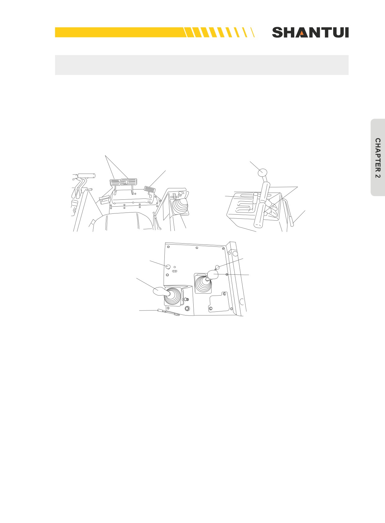
OPERATION | CONTROLS
CHAPTER 2: OPERATION
2.1 CONTROLS
2.1.1 GENERAL VIEW OF CONTROLS (FIGURE 2-1)
Brake pedal
Fuel control lever
Deceleration pedal
Steering lever
Gear shift lever
Gear shift lock lever
Ripper lock button
Blade control lever lock button
Ripper control lever
Blade control lever
Brake lock lever
Figure 2-1
25
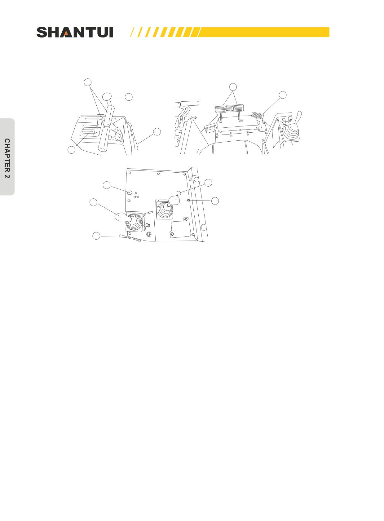
CONTROLS | OPERATION
2.1.2 ROLES OF VARIOUS CONTROLS (FIGURE 2-2)
3
4
5
1
7
2
11
8
9
10
6
Figure 2-2
26
OPERATION | CONTROLS
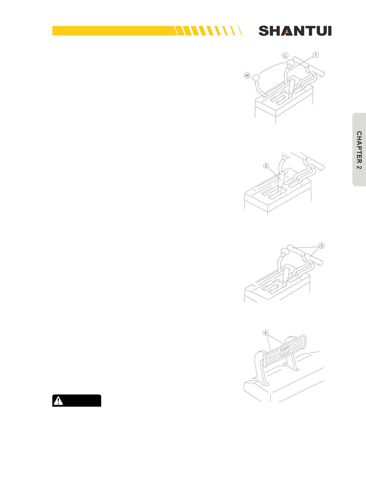
Fuel control lever (1) (Figure 2-3)
This control lever is used to control the engine speed and out-
put.
(L) The Low idling position
(H) The High speed position
Figure 2-3
The gear shift lever (2) (Figure 2-4)
There are three forward gears and three reverse gears. The
gear shift lever can be easily shifted, so that you can easily get
the speed you want.
(F: Forward; R: Reverse; and N: Neutral)
Figure 2-4
The steering lever (3) (Figure 2-5)
When the steering lever on one side is pulled to the middle po-
sition, the vehicle will slowly make a big turn to this side, and
when the lever continues to be pulled to the end, the vehicle
will make a turn on the original position.
Figure 2-5
The brake pedal (4) (Figure 2-6)
If you step down the two pedals in the middle, both the left
side and the right side will brake. Pull the steering lever on one
side to the middle position, and simultaneously step down the
brake pedal on the same side, the vehicle will make a turn on
the original position to the same side.
CAUTION
Figure 2-6
Do not place your foot on this pedal unnecessarily.
27
CONTROLS | OPERATION
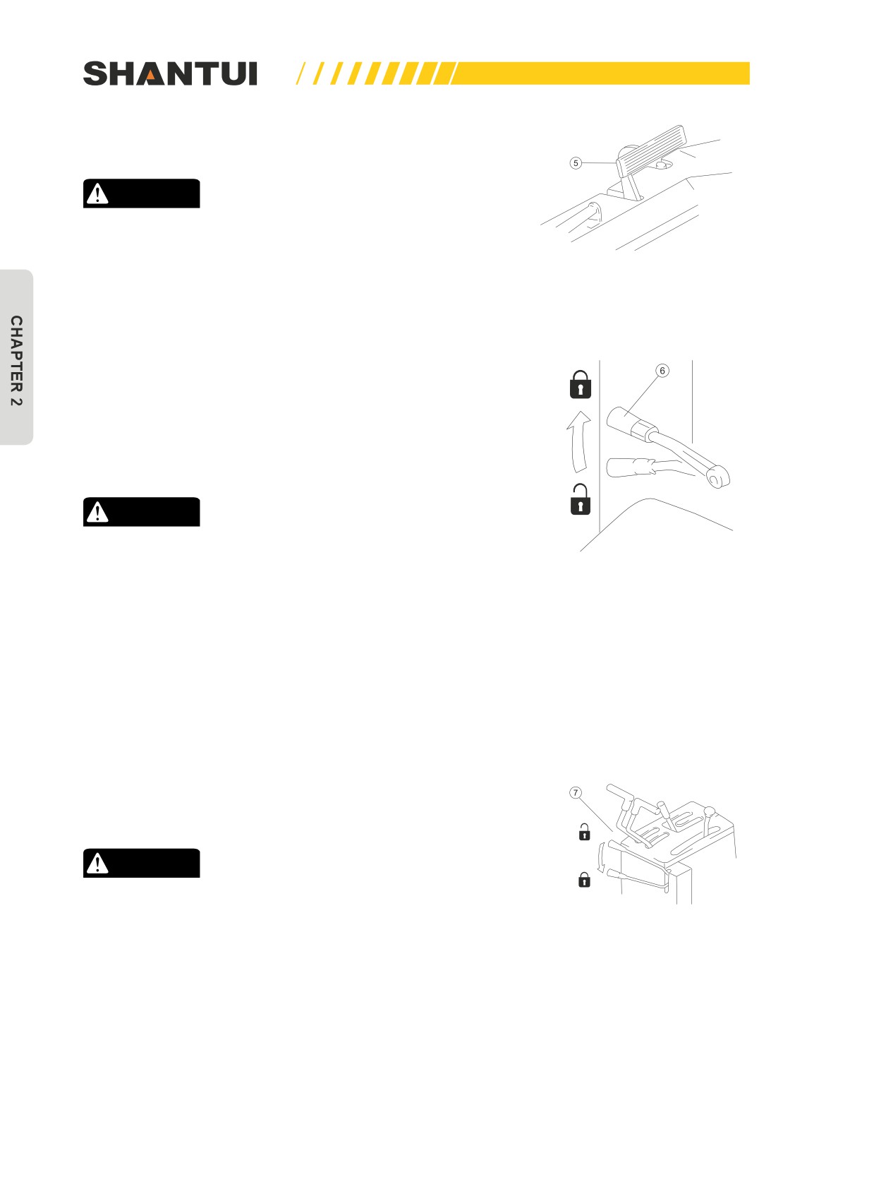
Deceleration pedal (5) (Figure 2-7)
This pedal is used to reduce the engine speed.
CAUTION
When passing over the top of a hill or when a load is
dumped over a cliff, the load is suddenly reduced, so
there is danger that the travel speed will also increase
Figure 2-7
suddenly. To prevent this, depress the decelerator pedal
to reduce the travel speed.
Brake lock lever (6) (Figure 2-8)
Lock
This device is used to lock the brake pedal when parking. De-
press the brake pedal, and push the lock lever to the LOCK
position, the brake will be locked. Depress the brake pedal,
and push the lock lever to the FREE position, the brake will be
released.
Free
CAUTION
• No matter when and where the machine is parked, the
brake pedal must be locked.
Figure 2-8
• Using the brake lock lever to lock the brake pedal to
stop the bulldozer must be performed when the engine
is running. This is because when the engine stops run-
ning, the hydraulic brake booster is in the non-working
state, so that braking force will be reduced. Be espe-
cially careful that parking on a slope is very dangerous,
so you must operate this locking mechanism when the
engine is running.
The gear shift’s lock lever (7) (Figure 2-9)
This device is used to lock the gear shift when parking.
Free
CAUTION
Lock
When the vehicle is stopped for a while, you must push
the gear shift lever to the NEUTRAL position, and push
Figure 2-9
the lock lever to the LOCK position.
28
OPERATION | CONTROLS
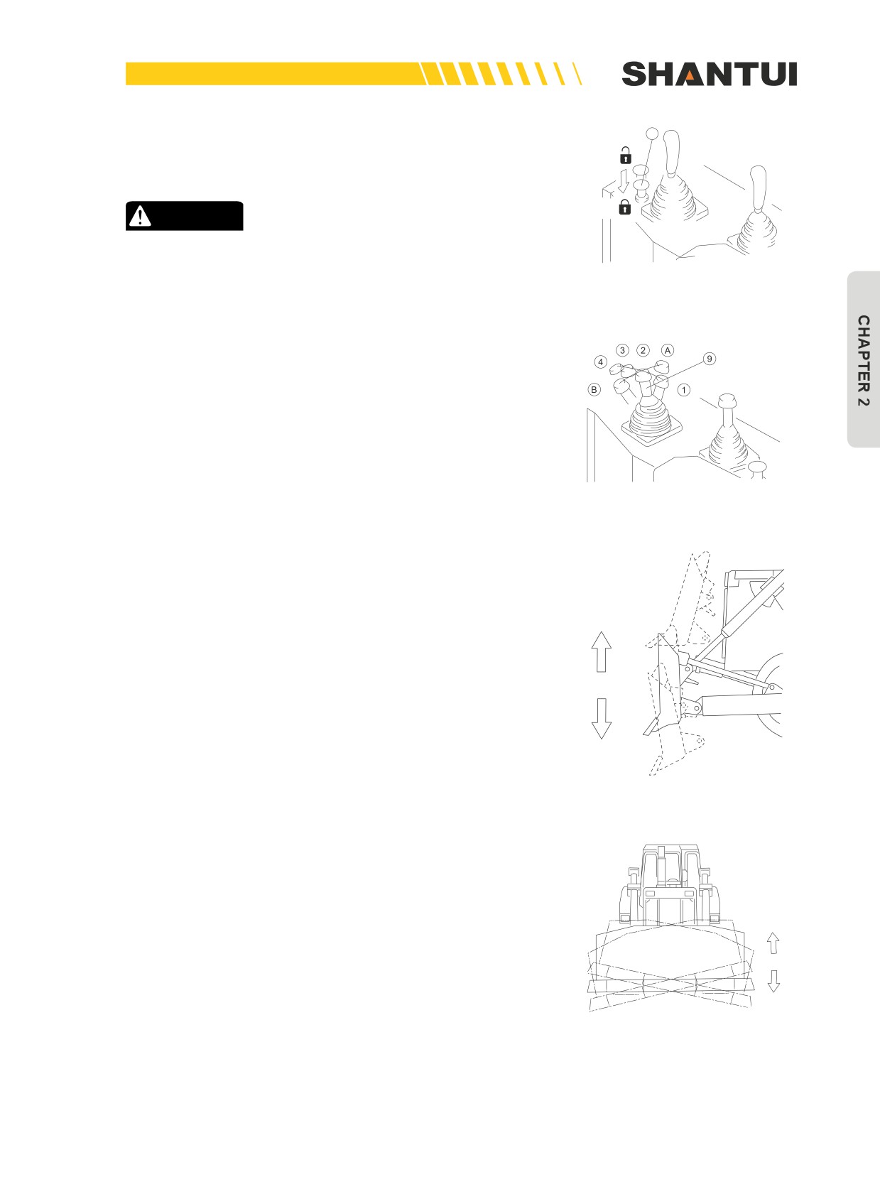
Blade control lever lock button (8) (Figure 2-10)
8
Press the button, the blade control lever is locked; pull out the
Free
button, the blade control lever is free.
Lock
CAUTION
When the vehicle is parked or during troubleshooting, the
blade should be put down, and the lock button should be
Figure 2-10
put to the LOCK position.
Blade control lever (9) (Figure 2-11)
The control lever is normally in the fixed position (2), Pull the
control lever to position (1), the blade is raised (Figure 2-12);
and push it to position (3), the blade is lowered; continue to
push it to position (4), the blade is in the floating state.
►►
When the control lever is in position (4), it cannot be auto-
matically bounced back to the fixed position (2), and must be
manually pulled back. When operating the straight tilt blade,
Figure 2-11
the control lever is pulled to position (A), and the blade is tilted
to the right; when it is pulled to position (B), the blade is tilted
to the left. (Figures 2-11 and 2-13)
►►
The blade can tilt when it is in any position between (1)
and (3);
►►
Positions (A) and (B) are used for straight tilt blade only;
Raise
►►
When the tilt cylinder reaches the end of its journey, the
control lever should be immediately pulled to fixed position (2);
►►
When the blade is at the highest point or the lowest point,
do not tilt the blade.
Lower
Figure 2-12
Right tilt
Left tilt
Figure 2-13
29
CONTROLS | OPERATION
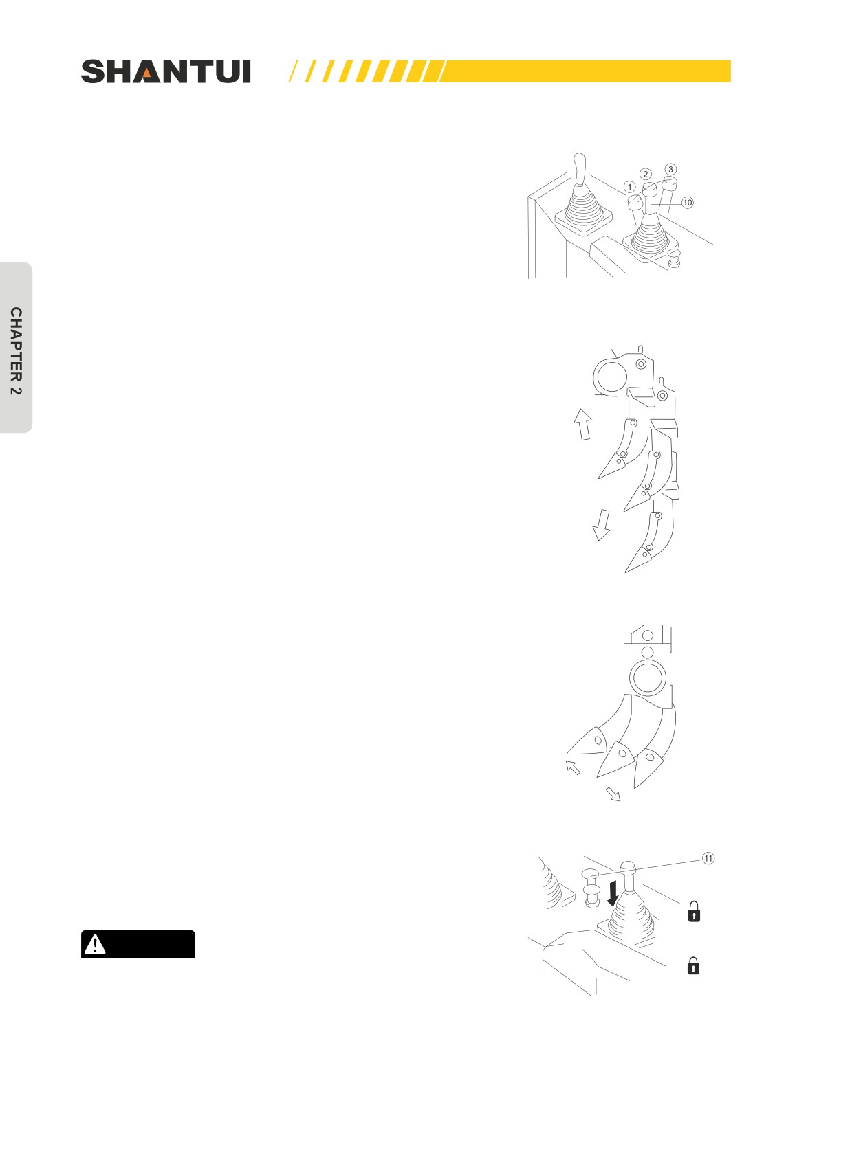
The ripper control lever (10) (Figure 2-14)
The control lever is normally in the fixed position (2). When the
control lever is pulled to position (1), the ripper is raised (Figure
2-15a); and when it is pulled to position (3), the ripper is low-
ered.
Press the button in the center of the control lever to move the
control lever to location (1), and the cutting angle of the ripper
will become smaller (Figure 2-15b); if it is moved to location (3),
the cutting angle of the ripper will become bigger.
Figure 2-14
Raise
Lower
Figure 2-15a
Smaller
Bigger
Figure 2-15b
The ripper lock button (11) (Figure 2-16)
Press the button, the ripper control lever is locked; pull out the
button, the ripper control lever is free and can go up and down.
Free
CAUTION
Lock
When the vehicle is parked or during troubleshooting, the
ripper must be put down, and the lock button be put to the
LOCK position.
Figure 2-16
30
OPERATION | CONTROLS
2.1.3 OTHER DEVICES
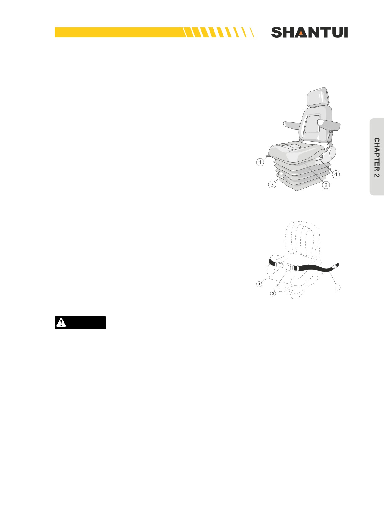
Adjusting operator’s seat (Figure 2-17)
Fore-and-aft adjustment: Pull lever "(1)" , set the seat to a po-
sition where it is easy to operate, and then release the lever.
Height adjustment of seat: Pull up knob "(2)" with both hands
to raise the seat. There is one knob "(2)" on left and right each
in symmetry.
Adjust reclining angle: Pull up lever "(4)", set the seatback to a
position where it is easy to operate, and then release the lever.
Adjust the softness of seat: Turn knob (3) clockwise, to make
the seat harder; and turn it counterclockwise, to make the seat
softer. You can adjust the seat to the most comfortable state
based on your weight.
Figure 2-17
Seat belt (Figure 2-18)
Fasten the belt using the following methods.
1. Adjust the seat by following the above steps.
2. After adjusting the seat position, adjust tether belt (1).
Tense the tether belt and install it when there is no one sit-
ting on the seat.
3. Sit on the seat and hold the buckle (2), insert the tongue
(3) in the buckle (2), and pull out the belt slowly so that the
belt will cover your abdomen sufficiently.
Figure 2-18
CAUTION
• Before fastening the seat belt, inspect the securing
brackets and belt for abnormal conditions.
• Inspect the belt for twisting.
31
//////////////////////////////////////////