Shantui SD22. Operation and Maintenance Manual - 3
DOZING OPERATION | OPERATION
Adjustment of straight tilt blade
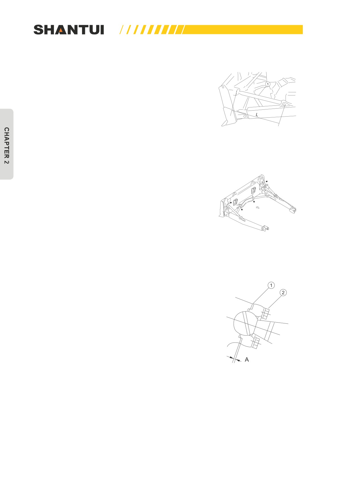
1. Adjustment of straight tilt blade’s tilt
• Simply operate blade control lever to let the blade tilt
425mm. If necessary, changing the left support arm’s
length L (Figure 2-80) can further tilt it to 500mm. The sup-
port rod’s length L is generally 1287mm, and the blade’s tilt
should be within 500mm. Do not attempt to tilt the blade to
more than 500mm, to prevent unwanted effect.
Figure 2-80
2. Adjustment of gaskets
• Adjust the thickness of the gaskets, to let the clearance of
the spherical joint in the axle direction be not over 1mm
(Figure 2-81, the position pointed by arrow).
• Remove gasket (1), and tighten bolt (2), to eliminate the
spherical joint’s clearance. (Figure 2-82) Measure the clear-
ance A, and remove bolt (2). Put in a gasket with a thick-
ness of A+1mm (1), and tighten bolt (2). Confirm if after the
bolt is tightened the spherical joint can flexibly rotate.
Figure 2-81
Figure 2-81
72
OPERATION | DOZING OPERATION
2.5.3 DOZING OPERATION
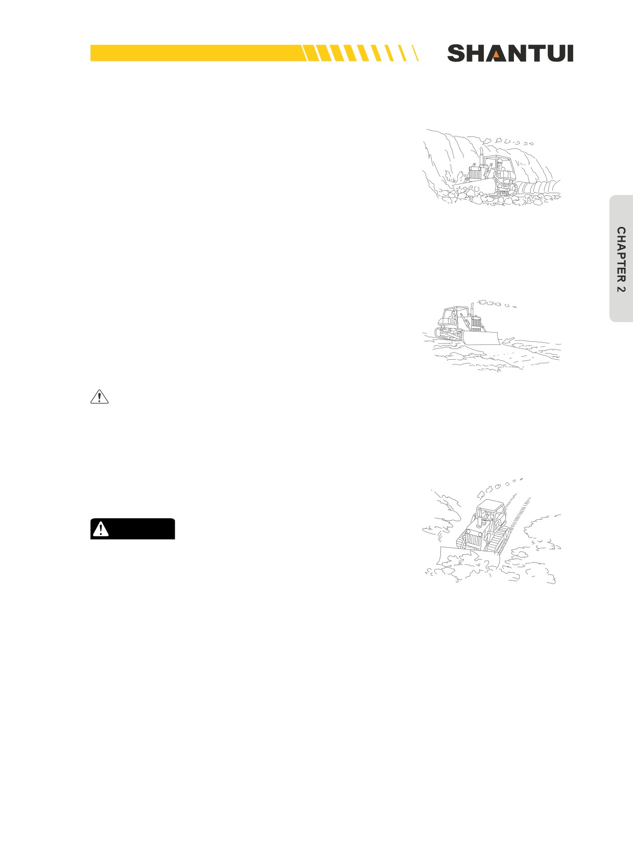
Cutting of hard earth or frozen earth (Figure 2-83)
When operating on hard earth or frozen earth, using straight
tilt blade or angle blade can effectively dig; if the earth is very
hard, using ripper can increase efficiency.
Figure 2-83
2.5.4 LEVELING OPERATION (FIGURE 2-84)
The uneven ground after excavating dozing can be leveled
using the following methods:
• Fill the blade with soil, let the vehicle run at a low speed,
and level the uneven areas when moving.
• Put the blade in the “floating” state, move the vehicle slowly
backward to smooth the ground.
Figure 2-84
Smoothing cannot be used on rocks, as it can damage
the blade.
2.5.5 DOZING SIDEWAYS
When dosing sideways, use the angle blade. (Figure 2-85)
CAUTION
• Do not use the blade to dig tree root etc.
• During dozing and moving, avoid sudden start, sudden
brake and sudden turn if possible.
Figure 2-85
73

DOZING OPERATION | OPERATION
2.5.6 METHODS FOR EXTENDING MACHINE LIFE
The life of the vehicle, especially the walking parts, is de-
pendent on the maintenance and operation methods to a
big extent. Therefore, remember the following points:
1. Select different models with different types of tracks ac-
cording to soil type.
2. During operation, reduce track slip as far as possible. If
the track slips, reduce the load until it no longer slips.
Figure 2-86
3. Avoid sudden start, sudden acceleration, unnecessary
high-speed operation, as well as sudden brake or sudden
turn if possible.
4. Always operate the vehicle to travel in a straight line as
far as possible. Do not always turn to one side. Turn to left
and right alternately and at the biggest radius.
5. During dozing, if the terrain forms a gentle slope to left or
right, reverse the vehicle to the level ground and level it
again. Do not continue to operate on the slope.
6. Do not let the vehicle try to handle a hard object or an ob-
stacle that is hard to handle, or the idler or Sprocket will
leave the ground. (Figure 2-86)
7. When operating on an inner slope, the vehicle should trav-
el along the slope from top to bottom, and should not cross
the slope. When travelling uphill, do not back. (Figure 2-87)
Figure 2-87
• Before operation, clear the big rocks and other obstacles
from the jobsite.
74
OPERATION | TOWING, LIFTING, TRANSP. & STORAGE
2.6 TOWING, LIFTING, TRANSPORTATION AND STORAGE
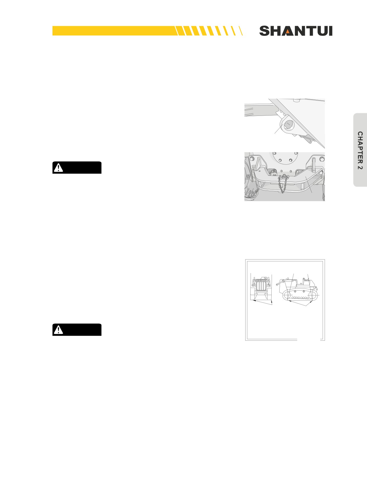
2.6.1 TOWING (FIGURE 2-88)
Towing is the operation to draw the bulldozer using the front
and rear towing devices for darwing or self-rescue.
►►
When using front and rear towing devices for drawing or
self-rescue, ensure that the towwing cables and the towing de-
vices can be reliably connected and locked, and that the tow-
Front towing bracket
ing cables can safely carry the towing load.
CAUTION
The effective safe load of the bulldozer’s front and rear
towing devices is 15tons.
Rear traction frame
Figure 2-88
2.6.2 LIFTING (FIGURE 2-89)
When the bulldozer is lifting, operate in the way shown in the
The craning positions of the
figure below.
entire bulldozer
►►
During lifting, ensure that the lift rope can be reliably
locked, and avoid the direct contact between the weight-bear-
ing point and the bulldozer’s edge (put a block beneath the
corner of the track). (Bulldozer’s dead weight: 23.4tons)
Craning position
Craning position
1. The craning positions of the vehicle
are shown in the figure.
2. Prior to craning, shut down the en-
gine, and put the entire vehicle in
CAUTION
the parked, braked and locked state.
09963- 02100
During lifting, ensure that the bulldozer is locked. (Step
Figure 2-89
down the brake pedal, and raise the brake lock lever)
75
TOWING, LIFTING, TRANSP. & STORAGE | OPERATION
2.6.3 TRANSPORTATION
During the vehicle transportation process, be familiar with and
abide by various road rules as well as the traffic rules including
the rules about the transportation of vehicles on the road and
the restrictions on vehicles. When going through bridges and
tunnels, measure the allowed weight of the bridges and the
space sizes of the tunnels.
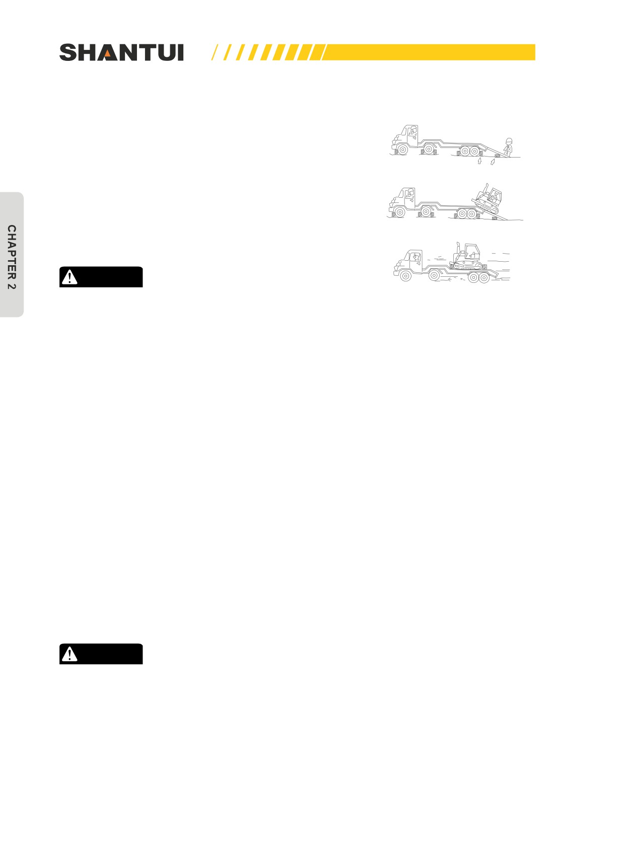
It’s best to create a special loading/unloading platform. If using
a ramp to load the machine to a trailer, follow the rules below.
(Figure 2-90)
CAUTION
Figure 2-90
When traveling up a ramp, do not adjust the travel direc-
tion. If you need to adjust the direction, back the vehicle
to the ground and make the adjustment.
1.
The brake of the trailer should be applied, and the wheels
are secured with blocks.
2.
Make sure the ramp has sufficient width, length and thick-
ness to enable the machine to be safely loaded and un-
loaded.
3.
Make the ramp properly aligned, and then slowly load/
download the machine.
4.
The vehicle should be put in the trailer’s appropriate posi-
tion, insert blocks beneath the track in front and back, and
then use solid and firm chains or ropes to secure it, to pre-
vent it from falling off during the transportation process to
cause accidents.
5.
Lower the blade, and put various levers to the following
positions.
•
Put the throttle control lever in the low-speed position, and
remove the starting key.
•
Put the gear shift lever in the NEUTRAL position.
•
Put the blade control lever in the KEEPING position.
•
Put the brake lock lever in the LOCK position.
CAUTION
•
If the blade head’s width is wider than the trailer’s
width, you can change the blade’s angle or unload it
and load it again.
•
For long-distance water transportation, take anti-rust
measures, and apply anti-rust oil to the exposed oil cyl-
inder’s piston rod etc.
76
OPERATION | TOWING, LIFTING, TRANSP. & STORAGE
2.6.4 STORAGE
Before storage
When you expect the machine will be stored for a significantly long period of time, be sure to take
the following measures, to reduce the repair work when using the machine again.
1. After cleaning each part of the machine, store the machine in a dry building. If the machine has
to be put outdoors due to limited conditions, put wood planks on the ground, put the machine on
the wood planks, and cover the machine with canvas.
2. Before putting into garage, add sufficient fuel and lubricant, and change new engine oil.
3. Apply a layer of lubricant on metal surface. (At the piston rod)
4. Remove the terminals of the battery, cover them properly or store them separately.
5. If you expect the ambient temperature can be lowered to below 0°C, add antifreeze to the cool-
ing water beforehand.
6. Set various control levers and pedals as follows:
►►
Put the gear shift lever to the NEUTRAL position.
►►
Put the throttle control lever to the LOW SPEED position.
►►
Put the blade control lever to the KEEPING position.
►►
Put the brake pedal to the FREE position.
During storage
Start the engine once a month, and operate the vehicle for a distance. This is in order to let the ma-
chine’s parts and the surface of the engine’s various areas have a new layer of oil membrane.
►►
When operating the work parts, wipe off the lubricant grease on the hydraulic piston rod.
After storage
After storage (if not covered or not performing the anti-rust operation once a month), you must do
the following before use:
1. Remove the engine oil pan and other drain plugs of the oil tank, to drain the mixed water.
2. Remove the cylinder cap, lubricate various air throttles and rock arms, and check the action of
air throttles.
3. In order to exhaust hydraulic system’s air, run the engine at a low speed, and operate as follows:
• Operate each hydraulic cylinder back and forth 4-5 times, and let the piston stop at a place
100mm from the end of its journey.
• Continue to operate each hydraulic cylinder back and forth 3-4 times to the end of its journey.
►►
If the engine runs at a high speed at the beginning or if the piston runs to the end of its journey,
then the air getting into it may damage piston disc.
4. After the engine is started, let it run, until the temperature reaches the required value.
77
STRUCTURE & PRINCIPLE | MACHINE STRUCT. & MAIN PARAMETERS
CHAPTER 3: STRUCTURE AND PRINCIPLE
3.1 MACHINE STRUCTURE AND MAIN PARAMETERS
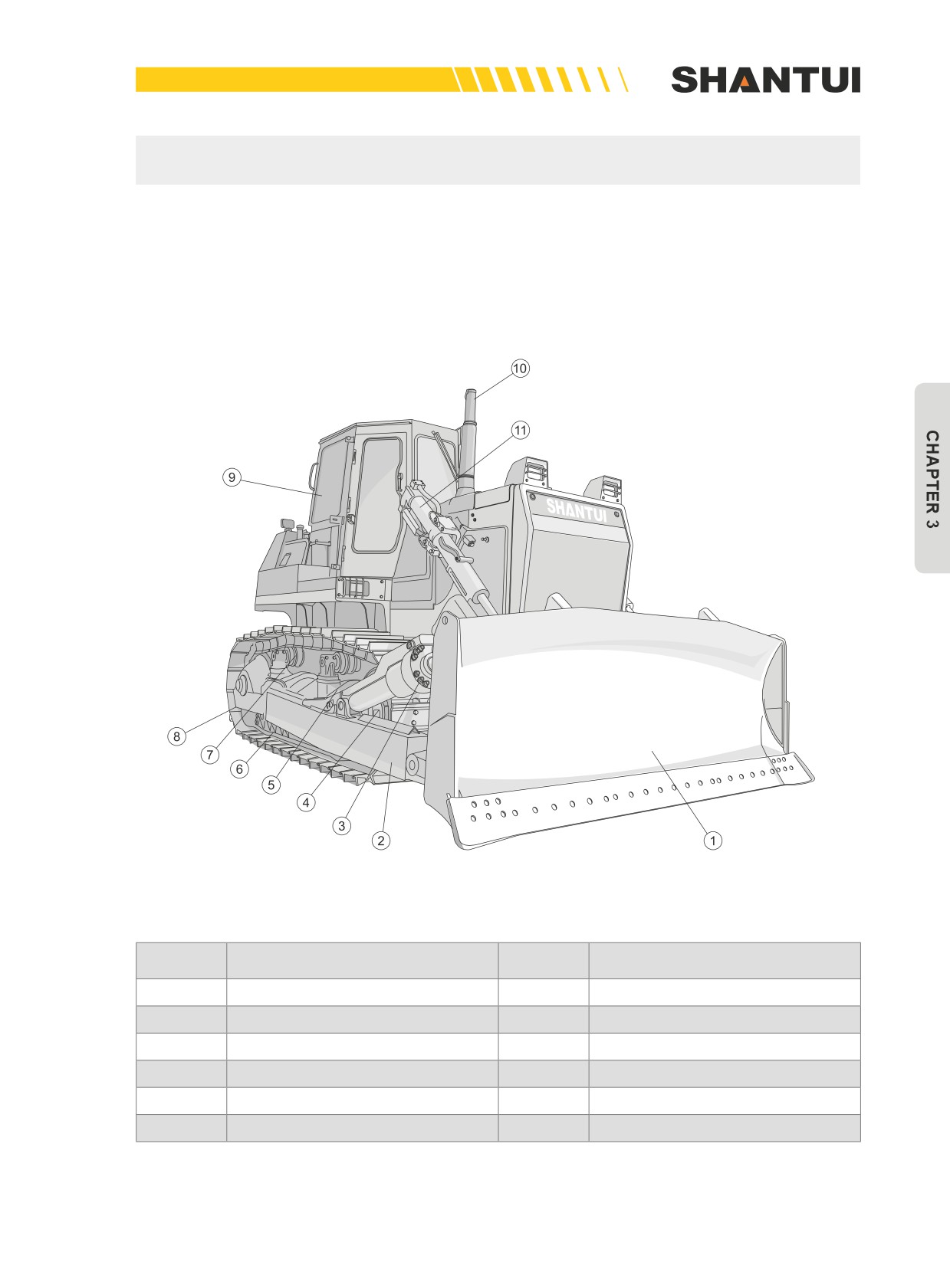
3.1.1 MACHINE APPEARANCE (FIGURE 3-1)
Figure 3-1
No.
Name
No.
Name
1
Blade
2
Push rod
3
Tilt oil cylinder
4
Idler
5
Track frame
6
Track roller
7
Carrier roller
8
Track
9
Cab
10
Exhaust pipe
11
Lift oil cylinder
79
MACHINE STRUCT. & MAIN PARAMETERS | STRUCTURE & PRINCIPLE
3.1.2 SPECIFICATIONS AND TECHNICAL PARAMETERS
Engine
Model
Cummins NT855-C280(BC III)
Weichai WD12
Inline, water-cooled, four-stroke, top-valve direct injection, and turbo
Type
diesel engine
Rate speed
1800rpm
Rate power
162kw (220HP)
175kW
Cylinder number-cylinder
6-139.7mmX152.4mm
6-126mmX155mm
diameter ×stroke
Piston displacement
14.01 L
11.596 L
Minimum fuel consumption
≤205g/kw.h(153g/ps.h)
208g/kW.h
Suitable altitude
Below 3000m
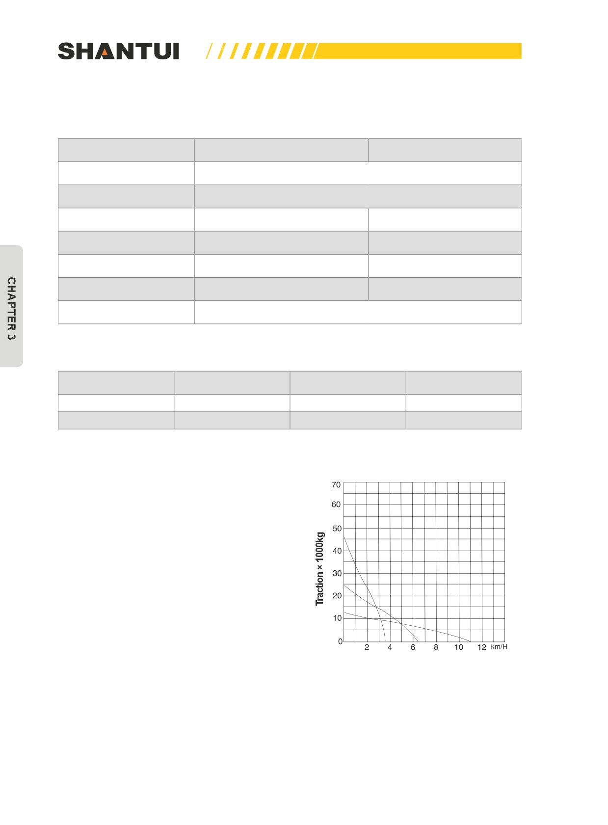
Travel speed (km/h)
Gear I
Gear II
Gear III
Forward
0~3.6
0~6.5
0~11.2
Reverse
0~4.3
0~7.7
0~13.2
Track performance curve
Lever’s traction and travel speed
Travel speed
Figure 3-2: Track performance curve
80
STRUCTURE & PRINCIPLE | MACHINE STRUCT. & MAIN PARAMETERS
Characteristics of the drive system
1. The hydraulic torque converter: three assemblies, single-level and single-phase.
2. Transmission case: planetary gear, multi-piece clutch, hydraulic, and forced lubrication.
3. Central drive: spiral bevel gear, primary reduction, and splash lubrication.
4. Steering clutch: wet, multi-spring pressed, hydraulic detach, and manual-hydraulic operation.
5. Steering brake: wet, floating band, and hydraulically assisted.
6. Final drive: two-stage straight gear reduction, and splash lubrication.
Walking system
Type:
Swing type of sprayed beam, suspended structure of equalizer bar
Number of carrier roller
2/each side
Number of track rollers:
SD22: 6/each side (four for one-sided and two for two-sided)
SD22E: 7/each side (four for one-sided and three for two-sided)
Track type:
SD22S: 8/each side (five for one-sided and three for two-sided)
SD22: Assembled single-track tooth (38 pieces each side)
Track shoe width:
SD22E: Assembled single-track tooth (41 pieces each side)
SD22S: Assembled arched triangle tooth (45 pieces each side)
SD22 and SD22E:
560mm (Straight tilt blade, angle blade)
610mm (U-Blade)
Track pitch:
SD22D:
610mm
SD22S:
910mm
216mm
81

MACHINE STRUCT. & MAIN PARAMETERS | STRUCTURE & PRINCIPLE
Dozing devices
SD22 and SD22E
SD22S
SD22D
Model
Parameter
Straight
Angle
U-Blade
Straight tilt blade
tilt blade
blade
Blade width (mm)
3725
4365
3800
4365
4365
Blade height (mm)
1315
1055
1343
1248
1248
Maximum Cutting Depth (mm)
540
535
540
550
550
Maximum lift height (mm)
1210
1290
1210
1330
1420
Blade-maximum tilt (mm)
>735
>500
>755
>500
>800
Maximum blade angle
(°)
/
25
/
/
/
Cutting angle (°)
55
55
55
55
55
Mass (Kg)
3630
3850
4196
3478
2900
Ripper
Type:
Parallelogram adjustable and removable
Number of gear teeth:
1-3 teeth
Pitch:
1000mm (Three teeth)
2000mm (Two teeth)
Maximum ripping depth:
665 mm
Maximum lift height:
555 mm
Mass:
2900 Kg
Hydraulic system (work equipment)
Maximum operating oil pressure: 14Mpa(140kg/cm2)
Oil pump type: gear oil pump
Flow: 262L/min (engine speed 1800rpm)
Control value type: Lubricating valve
Tilt cylinder’s inner diameter×quantity: Φ120mm×2 (dual-acting)
Tilt cylinder’s inner diameter×quantity: Φ200mm×1
Ripping oil cylinder’s inner diameter×quantity: Φ150mm×1
Ripper’s safety valve pressure: 16Mpa(160kg/cm2)
82
STRUCTURE & PRINCIPLE | MACHINE STRUCT. & MAIN PARAMETERS
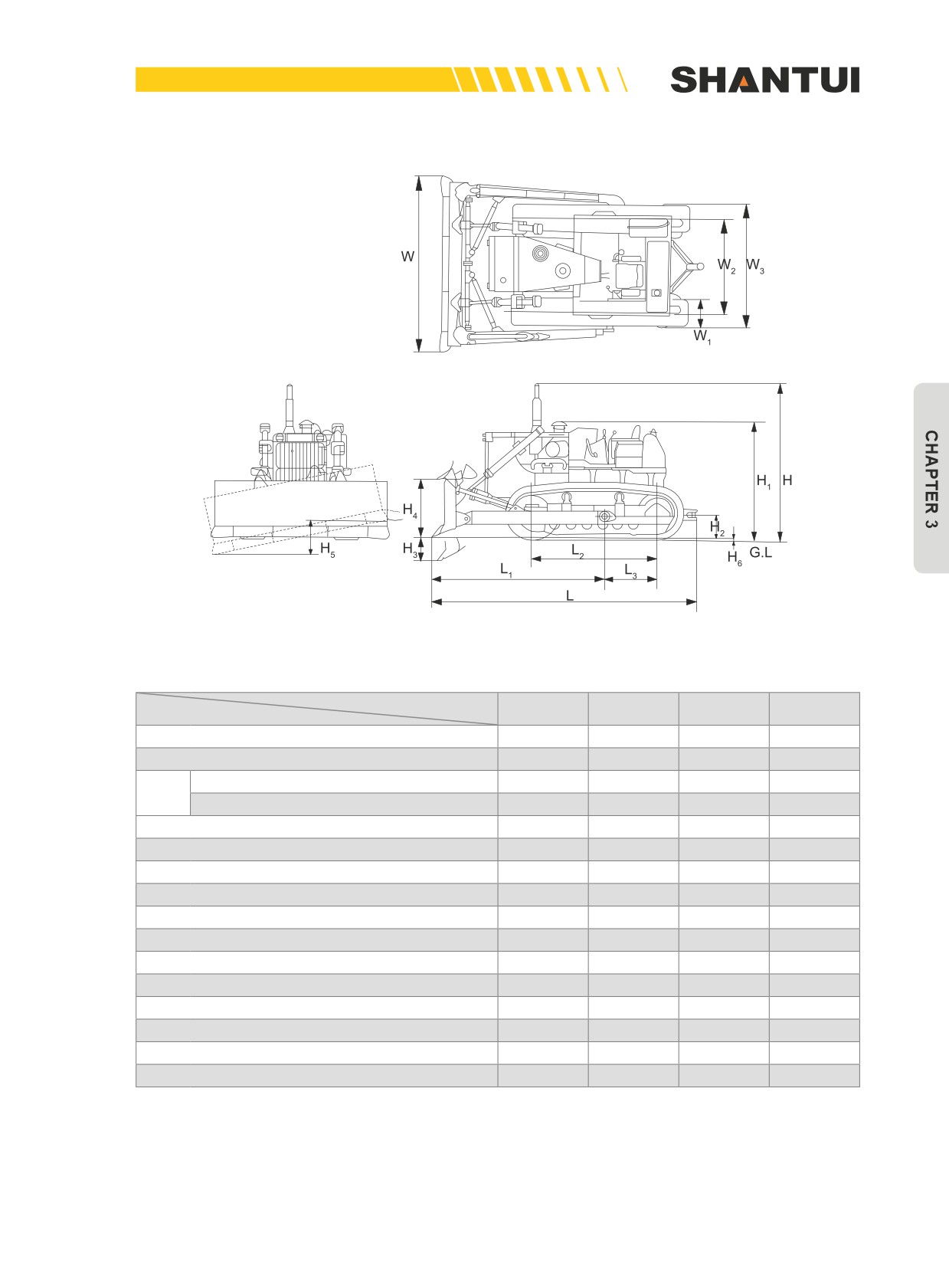
Dimensions (Unit: mm)
Figure 3-3
Unit: mm
Model
SD22
SD22E
SD22S
SD22D
Dimensions (Unit: mm)
L
5750
6000
6060
6150
W
3725
3725
4365
4365
Do not install the driver’s cab
3395
3395
3435
/
H
Install the 23Y-56B-00000 cab
3402
3402
3402
3807
L1
3725
3725
3850
3806
L2
2730
3050
3480
3050
L3
1155
1405
1595
1405
W1
560
560
910
660
W2
2000
2000
2250
2000
W3
2620
2620
3160
2660
H1
2610
2610
2645
2610
H2
470
470
805
470
H3
540
540
550
550
H4
1210
1416
1330
1420
H5
735
735
500
800
H6
72
72
123
72
Note: When H>3395. H is the distance from the top surface of the cab installed to the ground. For
SD22D, H is the height of the air cleaner’s cap from the ground.
83

MACHINE STRUCT. & MAIN PARAMETERS | STRUCTURE & PRINCIPLE
Other performance parameters
SD22 and SD22E
Model
SD22S
SD22D
Parameter
Straight
Angle
U-Blade
tilt blade
blade
Minimum ground clearance (mm)
405
405
405
513
405
19800
19800
19800
Tractor
22250
/
(21000)
(21000)
(21000)
Operating weight (kg)
23450
23670
24020
Bulldozer
25700
28000
(24600)
(24800)
(25200)
0.065
0.065
0.059
Tractor
0.034
/
(0.061)
(0.061)
(0.061)
Contact pressure (Mpa)
0.077
0.077
0.078
Bulldozer
0.041
0.070
(0.072)
(0.072)
(0.073)
3300
3300
3300
Minimum turning radius (mm)
3800
4100
(4000)
(4000)
(4000)
Slope climbing performance
30
30
30
30
30
Caterpillar’s central distance (mm)
2000
2000
2000
2250
2000
Single blade capacity (m3)
5.6
4.2
6.2
5.9
5.9
Productivity (m3/h)
330
245
365
345
345
Note: Operating weight and contact pressure do not include the weight of the cab and the ripper.
Productivity refers to the theoretic value for transporting 40 meters.
The parameter values within the parentheses are the corresponding parameter values of SD22E
84
STRUCTURE & PRINCIPLE | MACHINE STRUCT. & MAIN PARAMETERS
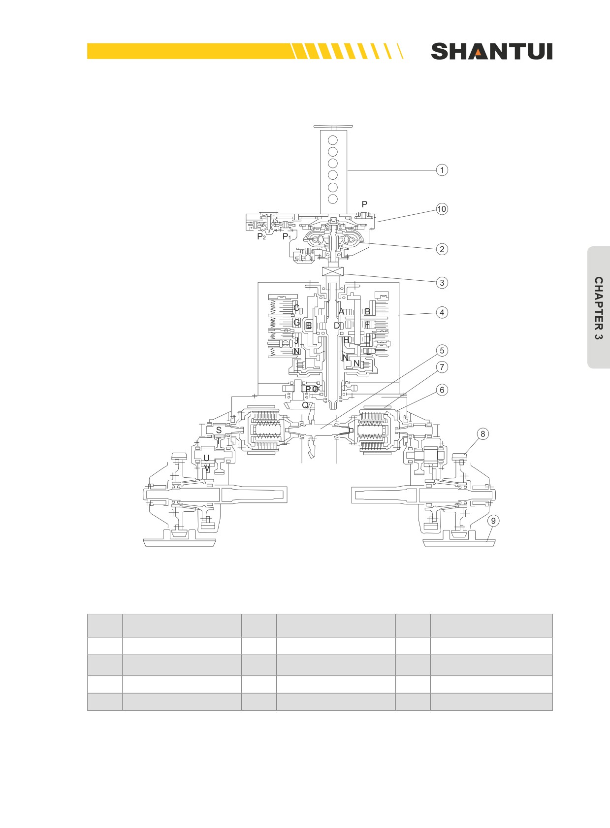
TRANSMISSION PRINCIPLE ILLUSTRATION (FIGURE 3-4)
Figure 3-4
No.
Name
No.
Name
No.
Name
1
Engine
5
Central drive
9
Walking system
Hydraulic torque con-
2
6
Steering clutch
10
Transfer case
verter
3
Universal joint
7
Steering brake
4
Transmission case
8
Final drive
85
ENGINE | STRUCTURE & PRINCIPLE
3.2 ENGINE
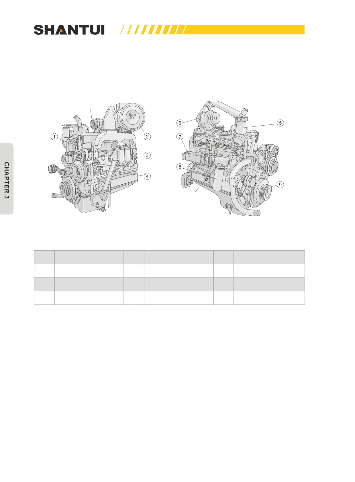
3.2.1 ENGINE APPEARANCE (SEE FIGURE 3-5,3-6)
To muffler
To starting motor
Figure 3-5
No.
Name
No.
Name
No.
Name
1
Alternator
4
P.T. Fuel pump
7
Oil cooler
2
Air cleaner
5
Anti Corrosion tank
8
Engine oil filter
3
Fuel filter
6
Tubocharger
9
Damper
86
STRUCTURE & PRINCIPLE | ENGINE
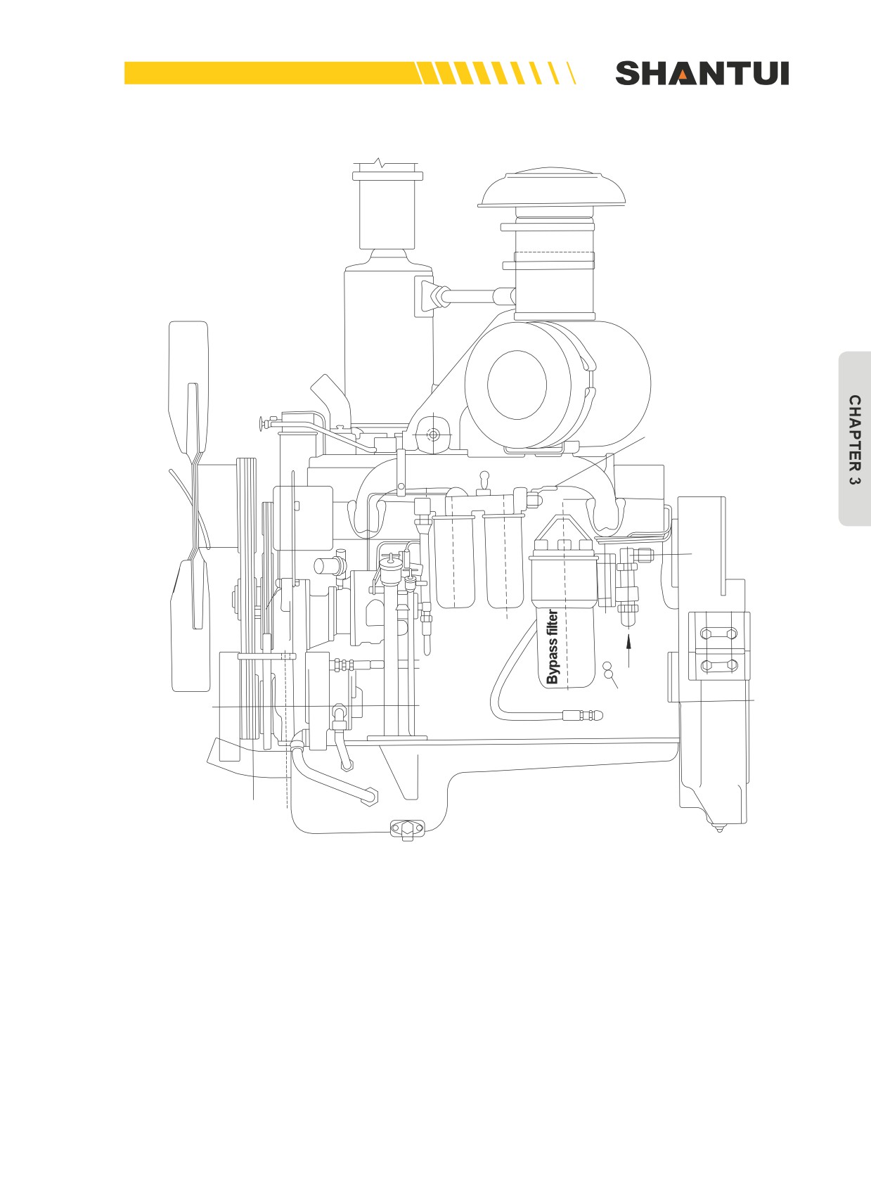
Fuel stop valve
(closed after the
machine is shut
down, and opened
before the machine
is started)
Oil scav-
enging
Hydraulic
Crankshaft's
connector
Center
Figure 3-6
87

ENGINE | STRUCTURE & PRINCIPLE
3.2.2 ENGINE’S MAIN PERFORMANCE INDICATORS
Main performance parameters
Engine Model
NT855-C280(BC III)
WD12
Number of cylinders-cylinder
6—139.7×152.4
6—126×155
diameter × stroke (mm)
Total replacement (L)
14.01
11.596
Ignition sequence
1-5-3-6-2-4
1-5-3-6-2-4
1691
1478.9
Overall length (mm)
(Flywheel housing ~ fan’s
(Flywheel-Fan pulley’s front
front end)
end)
1116
1110
Overall width (mm)
(Rear bracket~Rear bracket)
(Rear bracket~Rear bracket)
2741.9
2015.5
Overall height (mm)
(Exhaust pipe~Oil pan’s
(Pre-filter~Oil pan’s purge
purge valve)
valve)
Net weight(kg)
1750
1150
Rate speed (rpm)
1800
1800
Rate power (kw)
162(220PS)
175
Maximum torque (N•m/
1030/1250
1120
rpm)
Highest speed without
1950±50
1940+40
load (rpm)
Lowest speed without load
600±50
750±50
(rpm)
Minimum fuel consumption rate
≤205
208
(g/kw•h)
Silicon rectified generator
Silicon rectified generator
Charging engine
24V35A
24V55A
Starting form
Starting motor 24V11KW
Starting motor 24V6.6KW
Battery
24V195A-h×2
24V195A-h×2
Engine oil pan capacity (L)
45
30
Cooling water capacity (L)
20.8
22
Description of engine’s various systems
See engine’s User Manual for details.
88
STRUCTURE & PRINCIPLE | ENGINE
3.2.3 POWER OUTPUT DEVICES
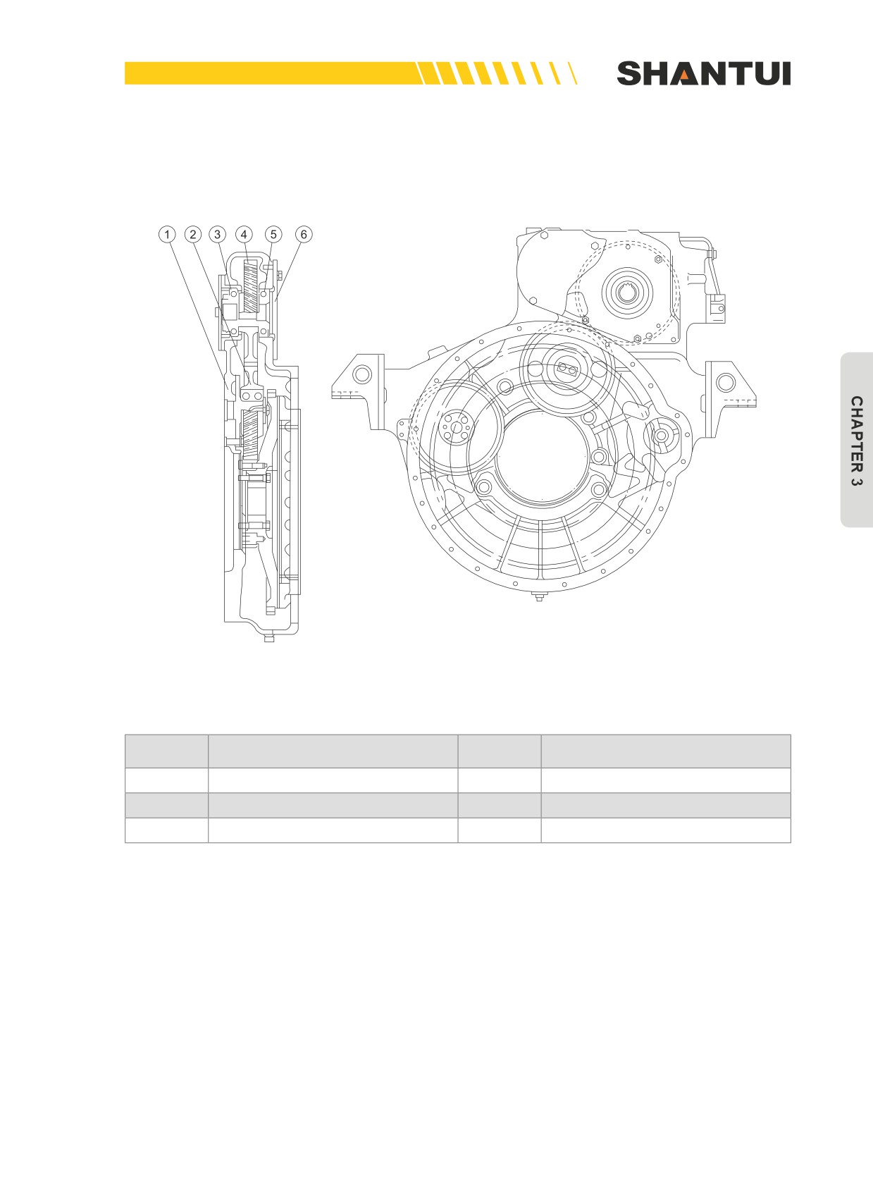
1. FLYWHEEL HOUSING ASSEMBLY (SEE FIGURE 3-7)
Figure 3-7
No.
Name
No.
Name
1
Flywheel housing
2
Idler (Z=51)
3
Bearing
4
Transfer case’s drive gear (Z=56)
5
Bearing
6
Cover
Its main function is power output.
89
ENGINE | STRUCTURE & PRINCIPLE
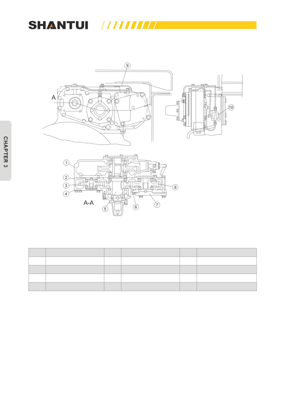
2. TRANSFER CASE (FIGURE 3-8)
Figure 3-8
No.
Name
No.
Name
No.
Name
1
Flywheel housing
5
Main shaft
9
Lubrication tube
2
Transfer case body
6
Driving wheel
10
Distributer
3
Driven wheel
7
Cover
4
Transfer case cover
8
Driven wheel
Transfer case is installed in the upper part of the flywheel’s housing. The gear in the upper part of
the flywheel’s housing drives the main axle (5) and the driving wheel (6) to rotate, thus making the
driven wheels (3) and (8) rotate. Remove cover (7) to install the working oil pump. Driven wheel (3)
drives the transmission pump. Install the steering pump on the front side of the flywheel’s housing.
The lubricating oil of the transfer case’s gear and bearing comes from the oil cooler’s oil returning
hose, to be distributed by the distributor (10), and drop to various related parts via the lubricating
pipe (9).
90
STRUCTURE & PRINCIPLE | ENGINE
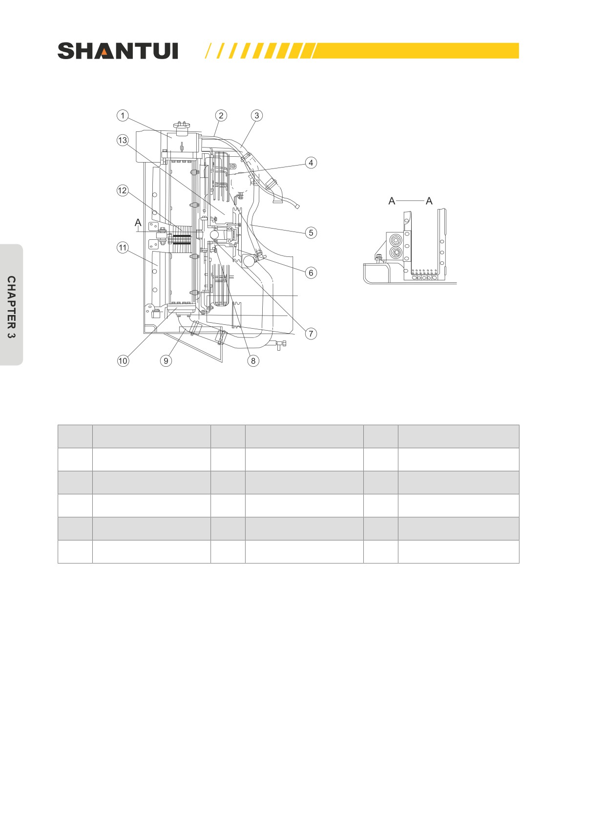
3.2.4 RADIATOR ASSEMBLY (SEE FIGURE 3-9)
Radiator mainly consists of upper box (1), radiator (12), lower box (10) and related attachments.
The cooling water flows through thermostat to enter upper box (1), removes air from water, and then
flows through the radiator core (12) to enter lower box (10). When the cooling water flows through
the radiator core (12), due to the role of the fan in the back end of the radiator, the water in the core
is cooled. The cooled cooling water is pumped out from lower box by water pump to the engine’s
cylinders.
This radiation system is a closed system. The pressure valve installed on the water tank maintains
water tank pressure within a range 0.075MPa lower than the gauge pressure, so as to increase the
evaporation temperature of the cooling water, to reduce water loss, and to increase cooling efficien-
cy.
The fan’s (13) power is transmitted by the V-shaped belt wheel on the front of the engine. The forced
air from the fan can enhance the cooling effect.
The SD22D bulldozer’s fan pulley (6) is designed to have two specifications. Small pulley is used in
summer, and big pulley is used instead in winter when the engine is too cold.
91
ENGINE | STRUCTURE & PRINCIPLE
From thermostat
Figure 3-9
No.
Name
No.
Name
No.
Name
1
Upper tank
6
Pulley
11
Guard
2
Hose
7
Shaft
12
Radiator’s core
3
Inlet pipe
8
Casing
13
Fan
4
Fan cover
9
Outlet pipe
5
Hose for adding water
10
Lower tank
92
STRUCTURE & PRINCIPLE | ENGINE
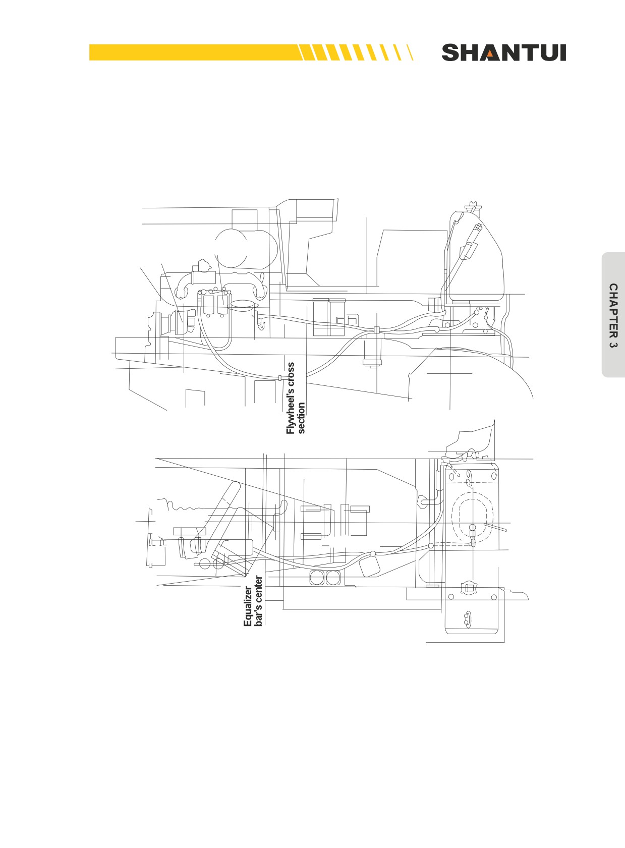
3.2.5 FUEL TANK AND PIPING (SEE FIGURE 3-10)
The fuel tank is installed in the back part of the vehicle. Fuel is injected into the fuel tank through the
filter screen. Removing the entrance’s cap, you can find the dipstick. Fuel flows from the fuel tank
into the fuel injection pump’s fuel filter The fuel tank has a fuel stop valve and an oil drain valve on
the back.
Guard plate’s
upper plane
Fuel filter
To Fuel pump
Crankshaft's
Center
Cross shaft’s
center
Vehicle body
center
Center of the
operator’s seat
Center of the
fuel tank
Figure 3-10
93
ENGINE | STRUCTURE & PRINCIPLE
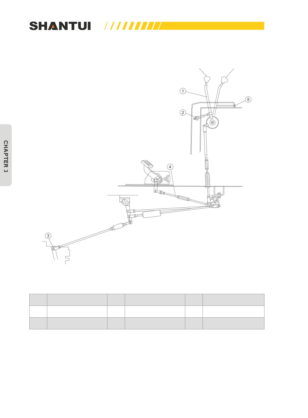
3.2.6 ENGINE OPERATION (SEE FIGURE 3-11)
IDlE
HIGH IDLE
Figure 3-11
No.
Name
No.
Name
No.
Name
High-speed adjustment
1
Fuel control lever
3
Rock arm
5
screw
2
Idle adjustment screw
4
Lever
94
STRUCTURE & PRINCIPLE | ENGINE
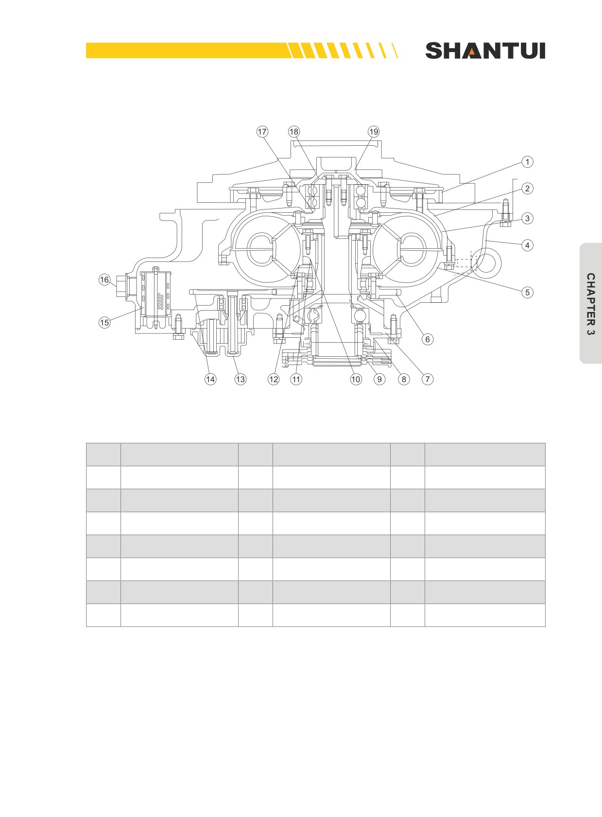
3.2.7 HYDRAULIC TORQUE CONVERTER (FIGURE 3-12)
Figure 3-12
No.
Name
No.
Name
No.
Name
1
Driving gear
8
Cover
14
Driving gear
2
Drive shell
9
Shaft coupling
15
Coarse strainer
3
Turbine
10
Turbine output shaft
16
Discharge outlet
Torque converter hous-
4
11
Guide roller axle's hub
17
Turbine hub
ing
5
Pump impeller
12
Guide roller
18
Binder plate
6
Driving gear
13
Fuel pump housing
19
Guider
7
Guide roller’s axle
14
Driving gear
95
ENGINE | STRUCTURE & PRINCIPLE
This machine uses the three-component one-stage and one-phase hydraulic torque converter.
The pump impeller (5), turbine wheel (3) and guide roller (12) are full of the operating oil. When the
pump impeller (5) rotates, the pump impeller will force the oil to impact the turbine wheel’s blade, so
as to make the turbine wheel rotate. The oil flows from the turbine wheel into the guide roller, and
flows out of the guide roller, to enter the pump impeller’s intake and complete the cycling process of
the oil.
The guide roller can change the rotation movement of the liquid, so it make increase the turbine
wheel’s torque. But the turbine wheel’s torque changes with the operating conditions. Therefore,
when load increases, the turbine wheel will bear a higher resisting torque, so as to automatically
reduce speed. Therefore, the hydraulic torque converter can ensure the smooth operation of the ma-
chine.
The power input route is: Driving gear (1) → Drive shell (2) → Pump impeller (2).
The power output route is: Turbine wheel (3) → Turbine hub (17) → Turbine wheel’s output shaft (10).
96
STRUCTURE & PRINCIPLE | UNIVERSAL JOINT
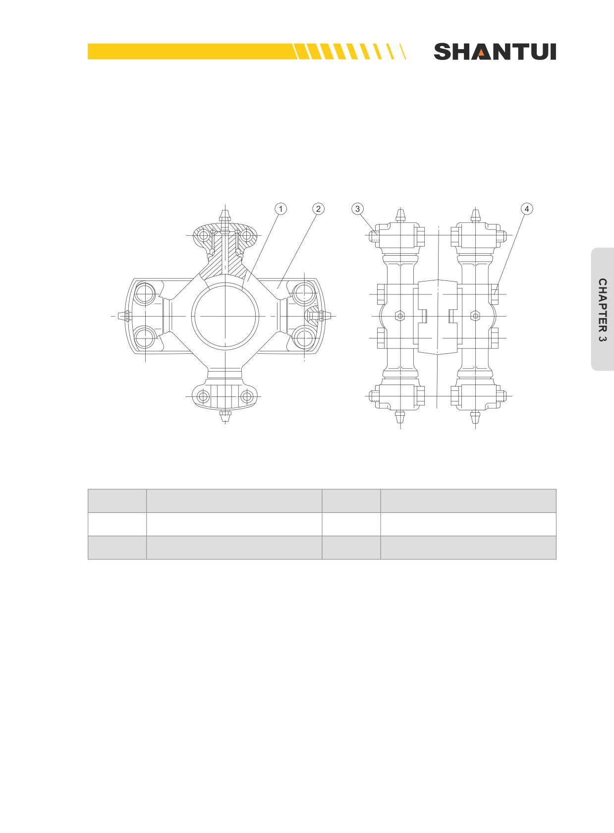
3.3 UNIVERSAL JOINT (FIGURE 3-13)
The role of the universal joint is to transmit the power between the hydraulic torque converter and
the transmission case. It can ensure that when the coaxiality of the turbine wheel’s output shaft
and the center line of the transmission case’s main is within the allowed range, the power can be
smoothly transmitted.
Figure 3-13
No.
Name
No.
Name
1
Cross shaft coupling assembly
2
Connecting plate
3
Bolt
4
Bolt
97
TRANSMISSION CASE | STRUCTURE & PRINCIPLE
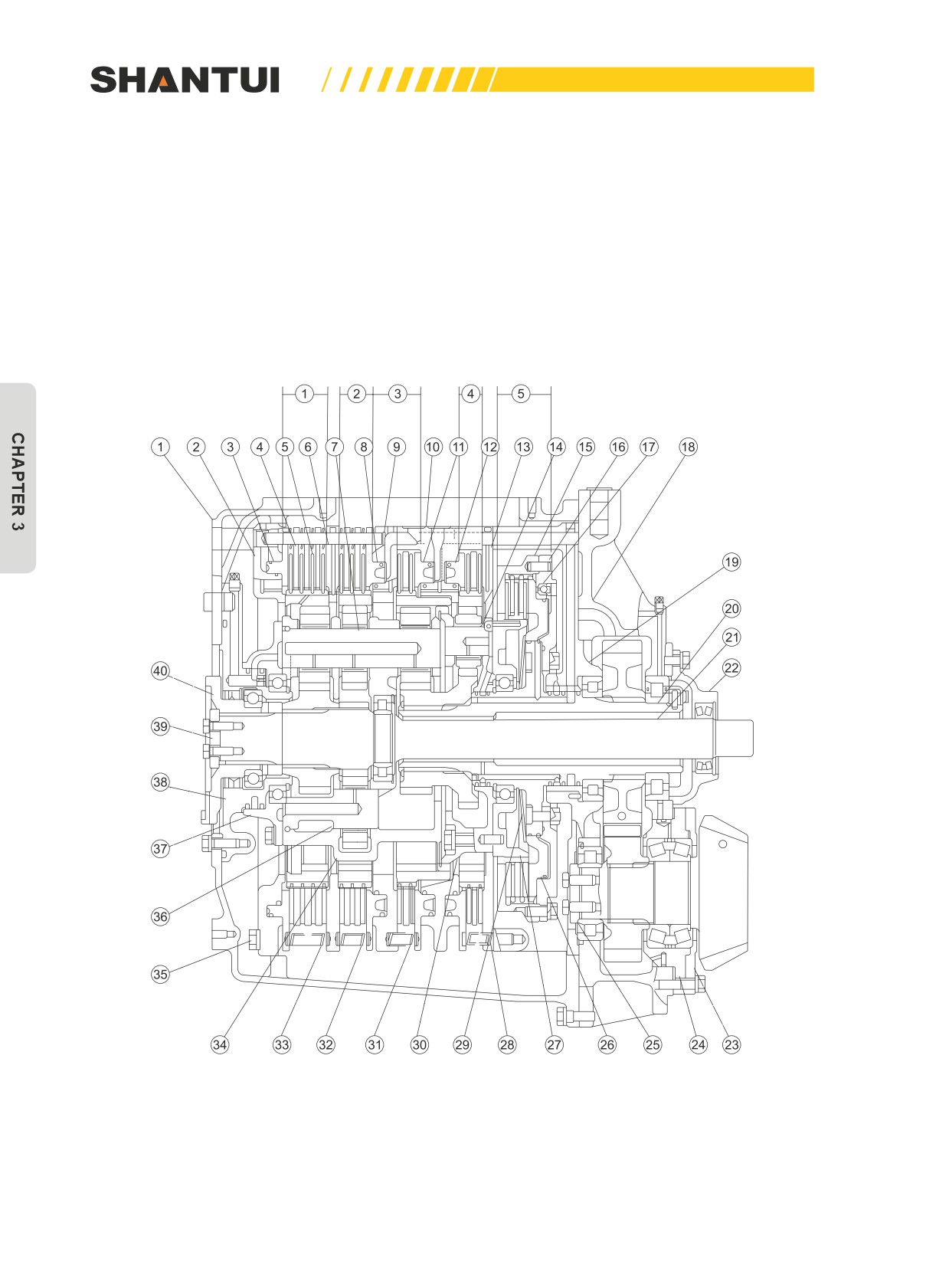
3.4 TRANSMISSION CASE (FIGURE 3-14)
The role of the transmission case is:
1. To realize the machine’s FORWARD and REVERSE.
2. To get different transmission ratios (including stopping).
• This machine uses the planetary gear multi-disc clutch structure. Relying on hydraulic force and
operated by the control valve, it can provide three forward gears and three reverse gears.
• No.1 Clutch is FORWARD, No.2 is REVERSE, No.3 is the third gear, No.4 is the second gear,
and No.5 is the first gear.
Figure 3-14
98

STRUCTURE & PRINCIPLE | TRANSMISSION CASE
No.
Name
No.
Name
1
Transmission case housing
21
Input shaft
2
The first clutch’s oil cylinder body
22
Bearing support
3
The first clutch’s piston
23
Cover
4
The brake’s driving disc
24
Bearing Cover
5
Friction disk
25
Bearings’ guard plate
6
Plate
26
The fifth clutch’s piston
The first, the second and the third
7
27
The fifth clutch’s inner hub
rows of planetary pinion’s axis
8
The second clutch’s piston
28
The fourth planetary row's spring
9
The second clutch’s oil cylinder body
29
Butterfly-shaped spring
The third and the fourth clutchs' oil
10
30
The fourth row of carrier
cylinder body
11
The third clutch’s piston
31
The third planetary row's spring
12
The fourth clutch’s piston
32
The second planetary row's spring
13
Plate
33
The first planetary row's spring
The fourth row of planetary pinion’s
The first, the second and the third
14
34
axis
rows of carrier
15
The fifth clutch’s outer hub
35
Bolt
The second row of planetary pinion’s
16
The fifth clutch’s oil cylinder body
36
axis
17
Check valve’s steel ball
37
Bearing support
18
Box body (Rear)
38
Bearing support
19
Housing body
39
Retainer
20
Out sleeve
40
Shaft coupling
Gear position
Working clutch
Gear 1
No.1, No.5
FORWARD
Gear 2
No.1, No.4
Gear 3
No.1, No.3
Gear 1
No.2, No.5
REVERSE
Gear 2
No.2, No.4
Gear 3
No.2, No.3
99
TRANSMISSION CASE | STRUCTURE & PRINCIPLE
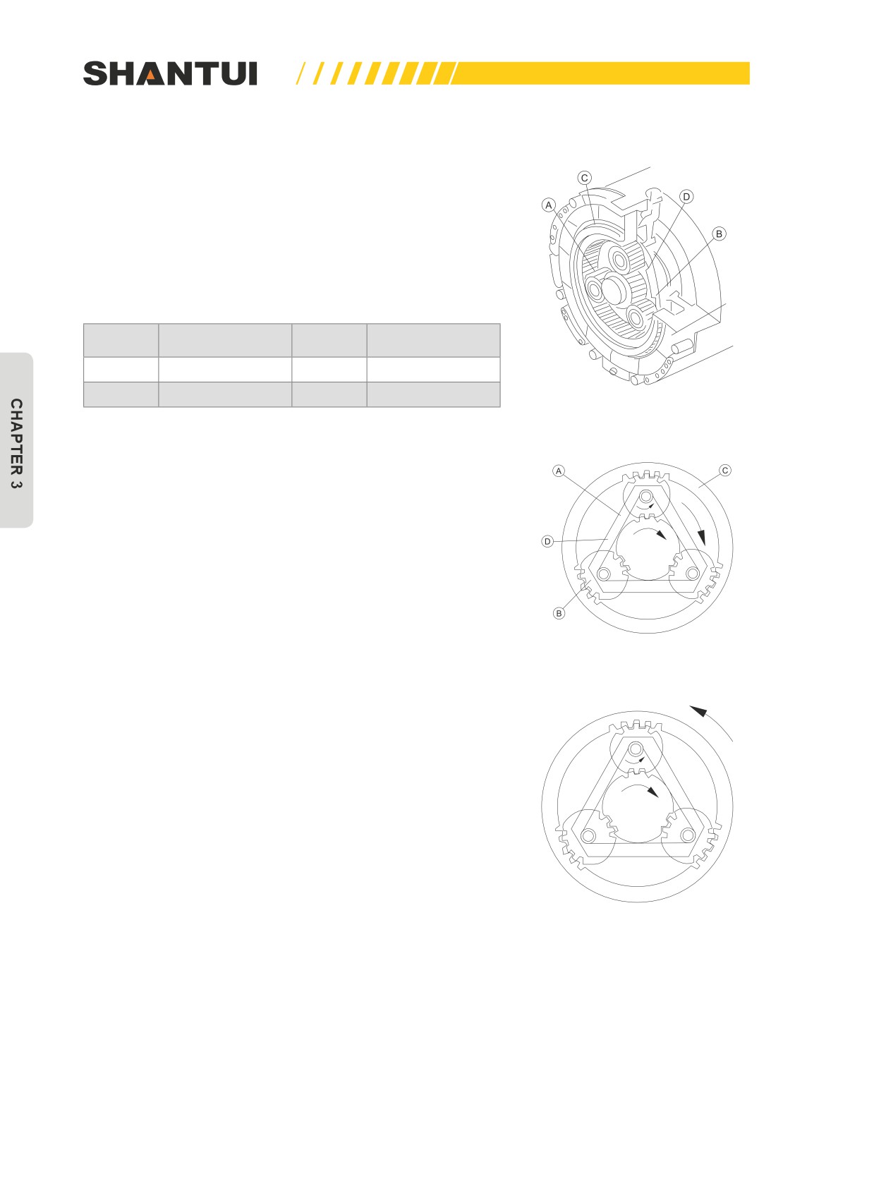
3.4.1 PLANETARY GEAR MECHANISM’S PRINCIPLE AND CLUTCH MECHANISM
Planetary gear’s operating principle (See figure 3-15)
The planetary gear mechanism shown in the figure is con-
sisted of sun wheel (A), planetary pinion (B), gear rim (C), and
carrier (D). planetary pinion (B) is installed on carrier (D). It
also engages with sun wheel (A) and gear rim (C) at the same
time.
Clutch
No.
Name
No.
Name
A
Sun wheel
B
Planetary pinion
C
Gear ring
D
Carrier
Figure 3-15
1. If the gear rim is fixed, the motion is transmitted from sun
wheel (A) to planetary pinion (B). In this case, planetary
pinion (B) rotates on its own on the one hand, and its axis
also revolves around sun wheel (A). In the structure shown
in the figure, the revolution direction of the planetary pin-
ion’s axis is the same as that of sun wheel (A). (See Figure
3-16) (See Figure 3-16)
Figure 3-16
2. If carrier (D) is fixed, the motion is transmitted from sun
wheel (A) to planetary pinion (B), and is again transmitted
by (B) to gear rim (C), to make gear rim (C) rotate. In the
structure shown in the figure, the rotation direction of gear
rim (C) is opposite to that of sun wheel (A). (See Figure
3-17) (See Figure 3-17)
Figure 3-17
100
STRUCTURE & PRINCIPLE | TRANSMISSION CASE
The above principle is the structural principle of the first, third,
and fourth rows of the planetary gear mechanism.
In the first row of the planetary gear mechanism, sun wheel (A)
is the driving part. In the third and the fourth rows of the plan-
etary gear mechanism, carrier (D) is the driving part.
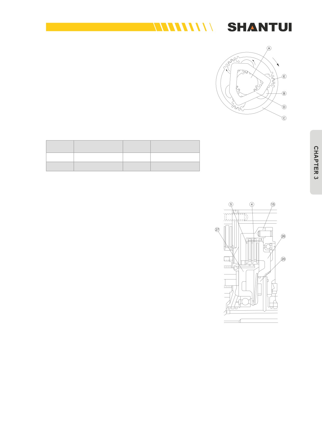
To obtain an output rotation direction opposite to that de-
scribed above, you just need to add a group of planetary gear
(E) (see Figure 3-18). The (A)→(B)→(E)→(C) motion trans-
mission form is the structural principle of the second row of the
planetary gear mechanism.
Figure 3-18
No.
Name
No.
Name
A
Sun wheel
B, E
Planetary pinion
C
Gear ring
D
Carrier
Various clutch mechanisms (see Figure 3-28)
The transmission case’s fifth row of clutch is a lock clutch.
Figure 3-19
101
TRANSMISSION CASE | STRUCTURE & PRINCIPLE
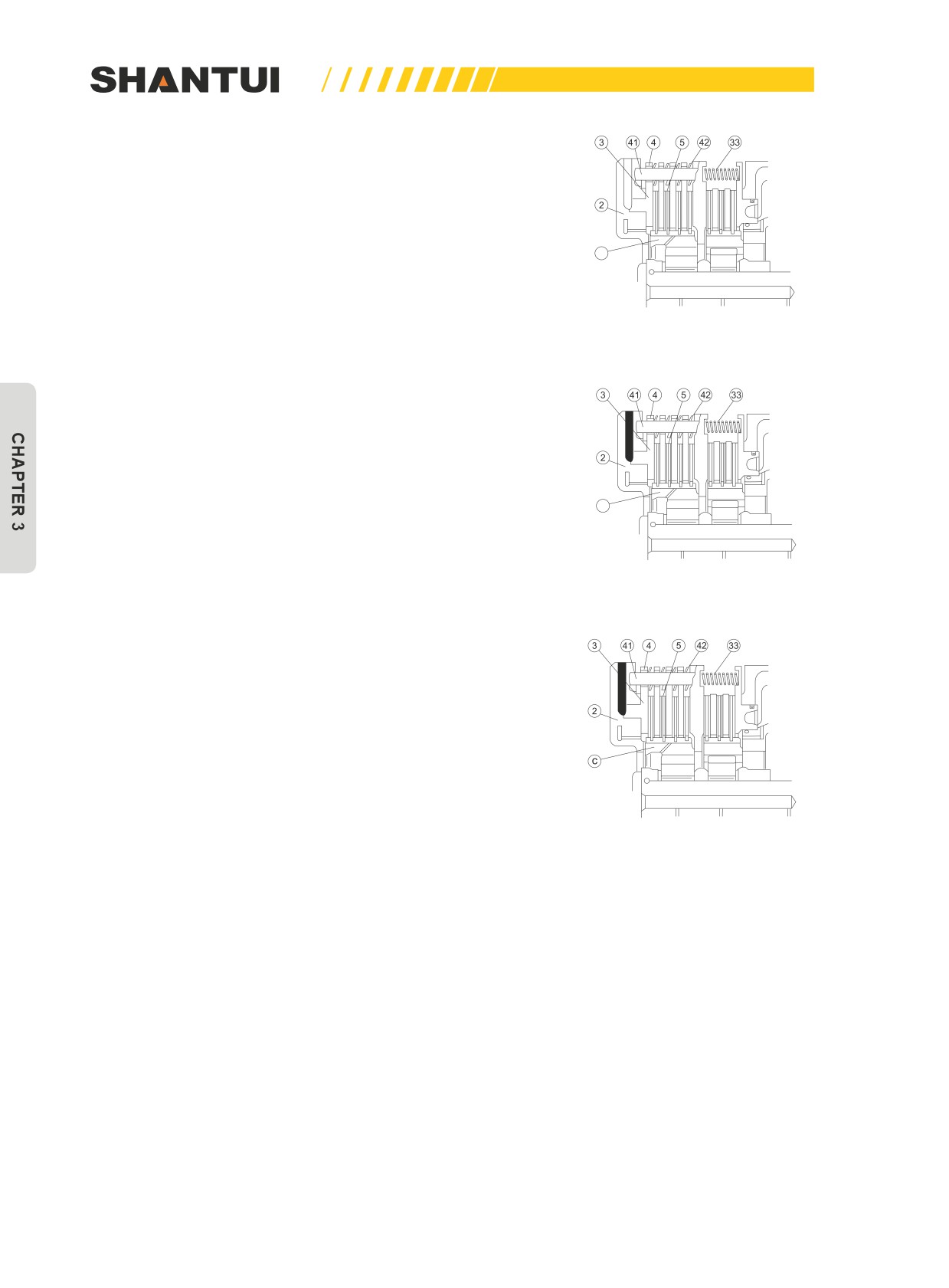
The fixing method for each row of the planetary gear rim is
shown in Figure 3-29. It is realized through clutch.
c
Figure 3-20
The engagement of clutch is realized by driving piston (3)
through the pressure from the control valve. (See Figure 3-21)
(See Figure 3-21)
c
Figure 3-21
The disengagement of clutch is realized by pushing piston (3)
to its original place through reset spring (33) after the pres-
sure oil is cut off (see Figure 3-22). (42) is the butterfly-shaped
spring. Its role is to accelerate the returning speed of piston (3),
to improve the separation effect of the driving and driven fric-
tion disks.
Figure 3-22
102
STRUCTURE & PRINCIPLE | TRANSMISSION CASE
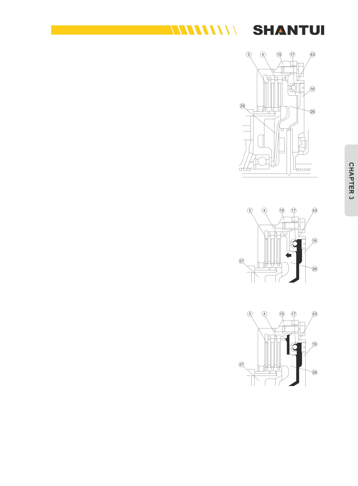
Figure 3-23 is the structural scheme of the fifth row of clutch.
When this clutch is disengaged, the working oil in the back
space of oil cylinder (16) is under the action of the centrifugal
force generated through rotation, and therefore relying on the
butterfly-shaped spring (29) alone can’t ensure the rapid sepa-
ration of the friction disks. This will put the clutch in a semi-
disengaged state, and a fault may occur when you change
the gear next time. In order to eliminate this phenomenon, the
steel ball check valve (17) is put inside.
Figure 3-23
When the fifth row of clutch is engaged (see Figure 3-24), the
pressure oil from the control valve enters the oil chamber to
push piston (26). Meanwhile, the pressure oil also pushes the
check valve’s steel ball (17), to block the valve seat’s orifice,
so that the clutch is rapidly engaged.
Figure 3-24
When the pressure oil from the control valve is cut off, due
to the centrifugal force, the steel ball (17) moves toward the
direction indicated by the arrow in Figure 3-25. In this case,
the valve seat’s orifice is opened, and the working oil in the
back space of oil cylinder (16) is drained out through the valve
seat’s orifice, to ensure the normal separation of the friction
disks.
Figure 3-25
103
TRANSMISSION CASE| STRUCTURE & PRINCIPLE
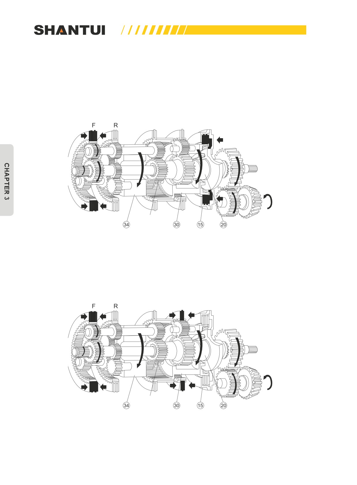
3.4.2 THE POWER TRANSMISSION ROUTE OF THE VARIOUS GEARS OF THE TRANSMIS-
SION CASE
Transmission route of the first gear FORWARD (See Figure 3-26)
In this case, the first and the fifth clutches are engaged at the same time.
The power transmission sequence is: A→B→(34)→J→O→P→Q (Clutches J, N, H, K, and L are
combined into one)
Gear 3
Gear 2
Gear 1
The output shaft
slides onto the
input shaft
Figure 3-26
Transmission route of the second gear FORWARD (See Figure 3-27)
At this point, the first and the fourth clutches are in the engaged state, and the first and the fourth
gear rims are fixed.
The power transmission route is: A→B→(34)→J→(30)→L→K→O→P→Q
Gear 3
Gear 2
Gear 1
The output shaft
slides onto the
input shaft
Figure 3-27
104
STRUCTURE & PRINCIPLE | TRANSMISSION CASE
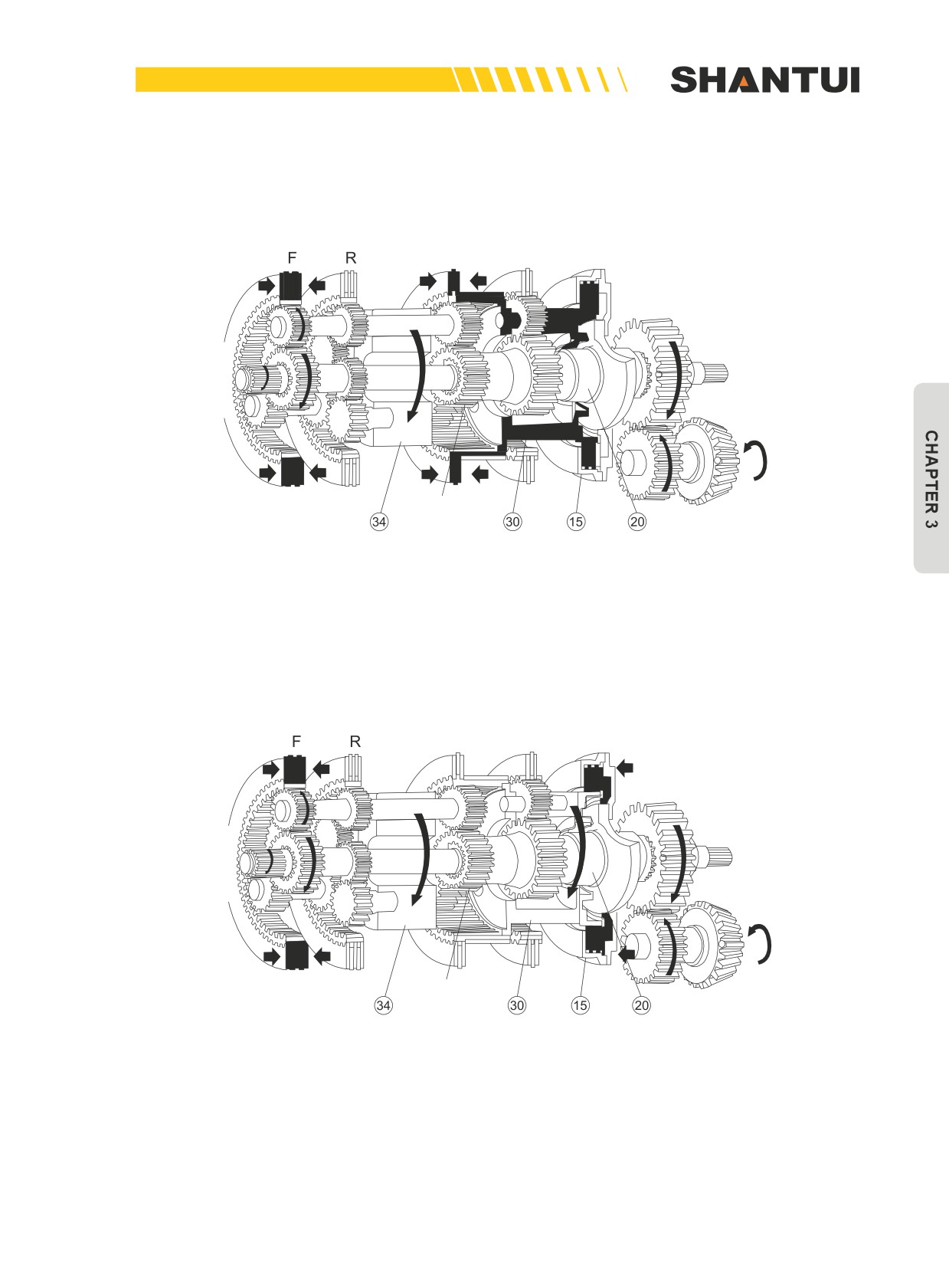
Transmission route of the third gear FORWARD (See Figure 3-28)
At this point, the first and the third clutches are in the engaged state at the same time.
The power transmission route is: A→B→(34)→J→I→H→O→P→Q
Gear 3
Gear 2
Gear 1
The output shaft
slides onto the
input shaft
Figure 3-28
Transmission route of the first gear REVERSE (See Figure 3-29)
At this point, the second and the fifth clutches are in the engaged state at the same time.
The power transmission sequence is: D→E→F→(34)→I→J→O→P→Q (Clutches J and K are com-
bined into one)
Gear 3
Gear 2
Gear 1
The output shaft
slides onto the
input shaft
Figure 3-29
The transmission route of the second gear REVERSE and the third gear REVERSE is omitted.
As long as the second and the fourth clutches can be engaged at the same time, you can get the
second gear REVERSE. And as long as the second and the third clutches can be engaged at the
same time, you can get the third gear REVERSE.
105
CENTRAL DRIVE | STRUCTURE & PRINCIPLE
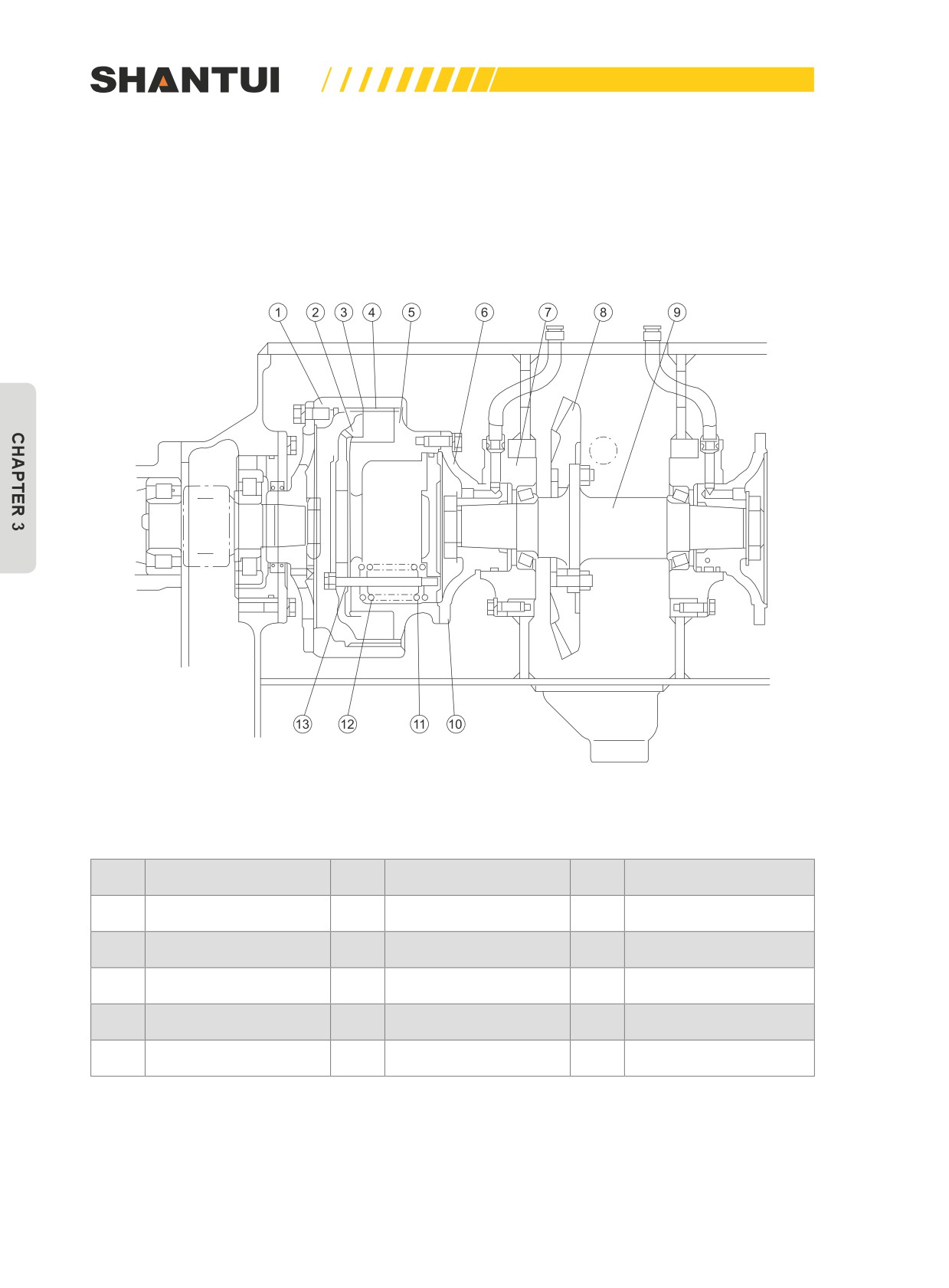
3.5 CENTRAL DRIVE (SEE FIGURE 3-30)
The main role of the Central drive is: 1. To change the power transmission direction (to change from
longitudinal to horizontal). 2. To apply primary reduction, to increase torque. The Central drive, the
steering clutch and the steering brake are all installed in the cavity of the steering case.
Figure 3-30
No.
Name
No.
Name
No.
Name
1
Outer hub
6
Hub
11
Big spring
2
Platen
7
Bearing support
12
Small spring
3
Outer friction disk
8
Big bevel gear
13
Bolt
4
Inner tooth
9
Cross shaft
5
Inner drum
10
Adjusting gasket
106
STRUCTURE & PRINCIPLE | CENTRAL DRIVE
The central drive consists of the big bevel gear (8) (engaged with the transmission case’s output
gear), the cross shaft (9), the bearing support (7), and the bearings. The correct engagement of a
pair of bevel gears can be achieved by adjusting the adjusting gasket (10) as well as the adjusting
gasket between the transmission case’s small bevel gear assembly and the housing. You can judge
it by checking the tooth side’s clearance and the engagement impression.
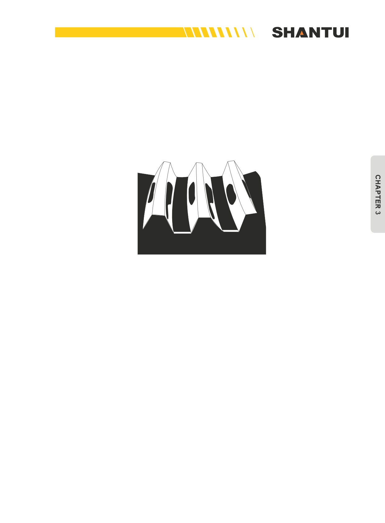
The standard clearance of a pair of the spiral bevel gears is 0.25~0.33mm. The engagement impres-
sion along the tooth length direction should not be smaller than half of the tooth’s length, and should
be closer to the smaller end along the tooth length direction (30% more on the smaller end). The
height should be half of the tooth’s height. See Figure 3-31.
Figure 3-31
107
CENTRAL DRIVE | STRUCTURE & PRINCIPLE
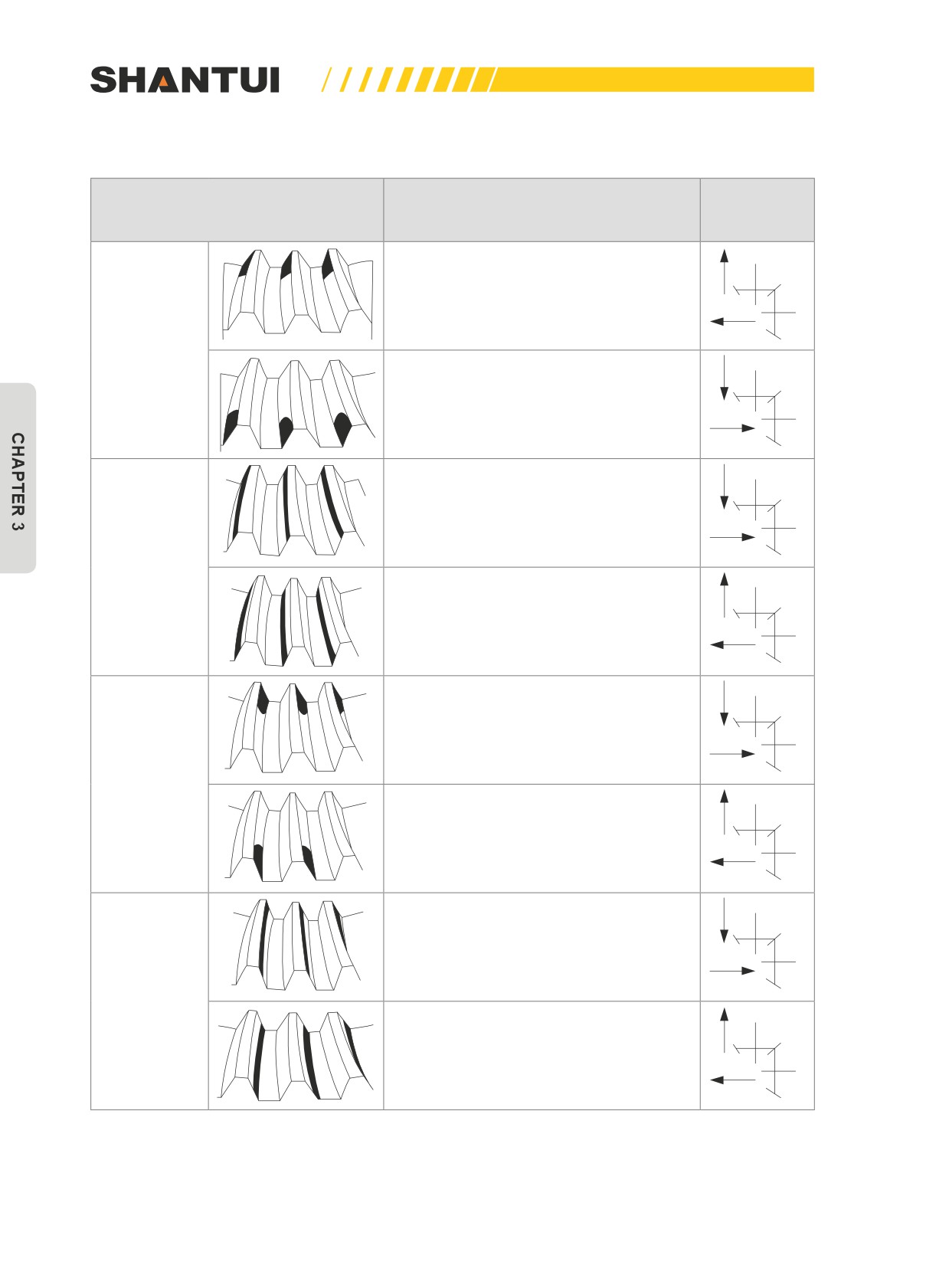
If the engagement is not normal, make adjustment using the methods in the table below.
Position of the contact impression
Gear moving
Adjustment method
on the passive tooth surface
direction
Move the driven gear toward the driv-
ing gear. If this makes the clearance too
small, move the driving gear outward.
FORWARD
Move the driven gear away from the driv-
ing gear. If this makes the clearance too
big, move the driving gear inward.
Move the driving gear toward the driven
gear. If this makes the clearance too
small, move the driving gear outward.
REVERSE
Move the driving gear away from the
driven gear. If this makes the clearance
too big, move the driving gear inward.
Move the driving gear toward the driven
gear. If this makes the clearance too
small, move the driving gear outward.
FORWARD
Move the driving gear away from the
driven gear. If this makes the clearance
too big, move the driving gear inward.
Move the driven gear away from the driv-
ing gear. If this makes the clearance too
big, move the driving gear inward.
REVERSE
Move the driven gear toward the driv-
ing gear. If this makes the clearance too
small, move the driving gear outward.
108
STRUCTURE & PRINCIPLE | STEERING CLUTCH
3.6 STEERING CLUTCH
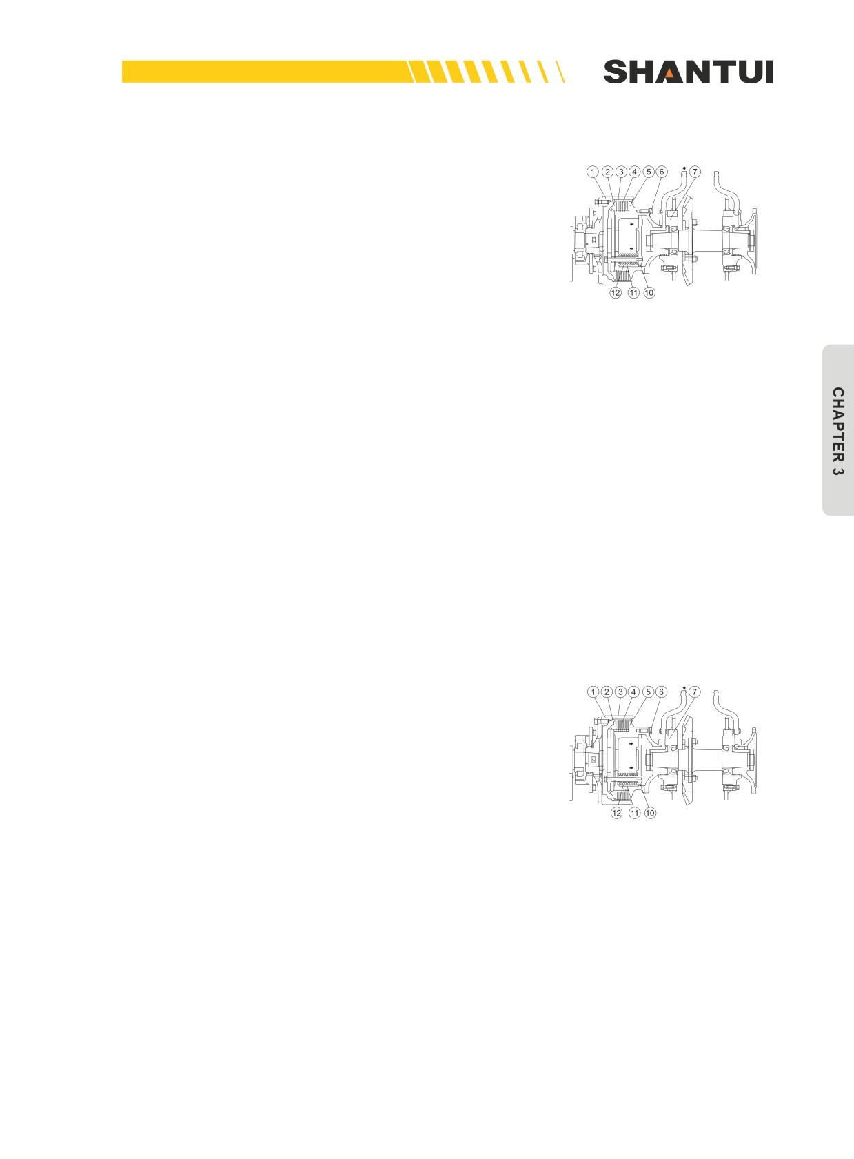
The steering clutches are located in the left & right chambers
of the steering case, with one on each side. Their role is to
connect or cut off the power from the central drive to the final
drive, to realize various actions including the entire vehicle’s
forward, reverse, turn, and stop.
Steering clutch’s structure mainly consists of the inner & outer
drums, the platen, the inner & outer friction disks, and the
Figure 3-32
spring.
This machine adopts a wet, multi-piece, spring-pressed, hy-
draulically-detached long-engagement structure.
Normally, due to the spring, the inner & outer friction disks are
connected, and the power from the cross shaft is transmitted
to the final drive disc through wheel (6)→inner drum (5)→inner
tooth (4)→outer friction disk (3)→outer drum (1).
When the steering lever is pulled, the pressure oil from the
steering control valve enters the inner cavity of the inner drum
(6) (See Figure 3-32) to push the piston (10), bolt and platen
(2) to move to the arrow direction (Overcome the pressure of
the big and small springs), so as to disengage the friction con-
nection between the inner tooth (4) and the outer friction disk
(3), to stop the outer drum (1) from rotating, so as to cut off the
power transmission.
When the steering lever is released, the oil pressure is cut off,
and due to the pressure of the big & small springs, the above
parts are forced to move in the direction indicated in the fig-
ure, to enable the inner tooth (4) and the outer friction disk to
become engaged, to realize the transmission of power. (See
Figure 3-33)
Figure 3-33
109
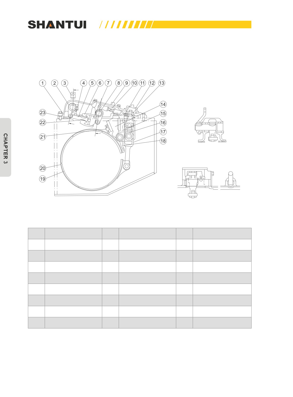
STEERING BRAKE | STRUCTURE & PRINCIPLE
3.7 STEERING BRAKE
This machine uses the wet, belt-style floating brake with a hydraulic booster.
A
B
A
B
A-A
B-B
Figure 3-34
No.
Name
No.
Name
No.
Name
1
Brake cover
9
Cover
17
Lever
2
Rock arm
10
Studs
18
Tail end
3
Rock arm
11
Adjusting spring
19
Brake lining
4
Spring
12
Cover
20
Brake band
5
Slide valve
13
Adjusting bolt
21
Spring
6
Valve body
14
Bracket
22
Bushing
7
Piston
15
Lever
23
Spring seat
8
Rock arm
16
Block
Its role is to hold the steering clutch’s outer drum tightly, to stop the final drive’s gear from rotating,
so as to let the vehicle turn or stop.
110
STRUCTURE & PRINCIPLE | STEERING BRAKE
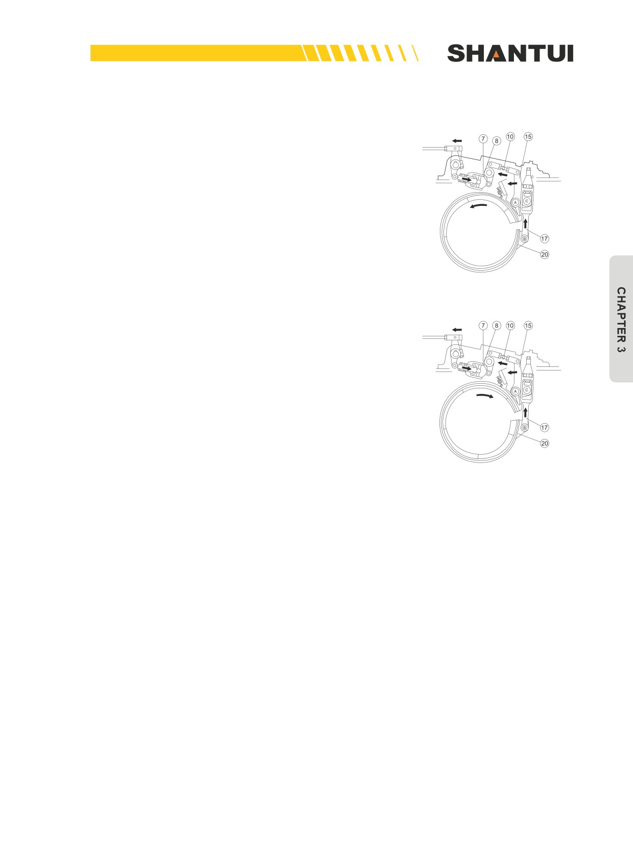
3.7.1 WORKING PRINCIPLE
When the vehicle moves forward, the steering clutch’s outer
drum rotates forward (See Figure 3-35). Slightly apply brake
force on the brake pedal, the clearance between the brake
band and the outer drum will be reduced until certain points
are in contact. Due to the friction force, the upper part of the
brake band pushes against the tail end, to let Pin A enter the
Forward
groove of lever (15). If the brake force continues to be applied,
rotation
lever (17), Pin B, and lever (15) will move in the arrow direc-
tion, to hold the outer drum tight. At this point, A is the fulcrum
of rotation.
Figure 3-35
When the vehicle moves in the reverse direction, the clutch’s
outer drum rotates backward (See Figure 3-36), whereas lever
(17), Pin B, and lever (15) move in the direction indicated in
the figure, to hold the outer drum tight. But at this point, the ro-
tation fulcrum has already been transferred Point C.
The brake results of the two are basically the same.
Backward
rotation
Figure 3-36
3.7.2 SERVO MOTOR VALVE’S WORKING PRINCIPLE
The use of the servo motor valve can dramatically reduce the
brake operation force of the driver. During braking, rock arm (2)
pushes slide valve (5), to make the clearance between slide
valve (5) and piston (7) disappear, and the oil pressure from
the pump pushes piston (7) to operate rock arm (8) to realize
braking. But due to the movement of piston (7), a clearance
will appear again between slide valve (5) and piston (7) for
sure. In order to ensure uninterrupted move, the brake pedal
must move continuously.
111
FINAL DRIVE | STRUCTURE & PRINCIPLE
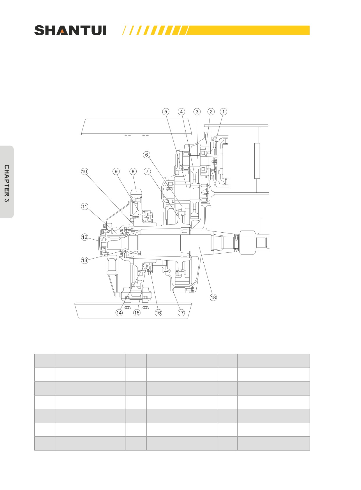
3.8 FINAL DRIVE
This machine uses the two-stage straight gear reduction mechanism.
The role of the final drive is to increase the output torque through the two-stage reduction, and at the
same time, to transmit the power through the sprocket to the walking mechanism.
Figure3-37: The final drive’s mechanism of SD22S and SD22R
No.
Name
No.
Name
No.
Name
1
Drive disc
7
Hub
13
Floating oil seal
2
Bearing support
8
Drive sprocket
14
Oil seal cover
3
Primary driving gear
9
Sprocket hub
15
Floating oil seal
4
Primary driven gear
10
Driving wheel's nut
16
Oil seal cover
5
Secondary driving gear
11
Support
17
Casing body
6
Secondary driven gear
12
Cover
18
Half shaft
112