NATIONAL DRILLING ASSOCIATION DRILLER’S MANUAL (2005) - page 3
Page 103 of 360
For best well efficiency, the percentage of open area in the screen should be the same as, or
greater than, the average porosity of the aquifer material. Typical porosities for sandstone
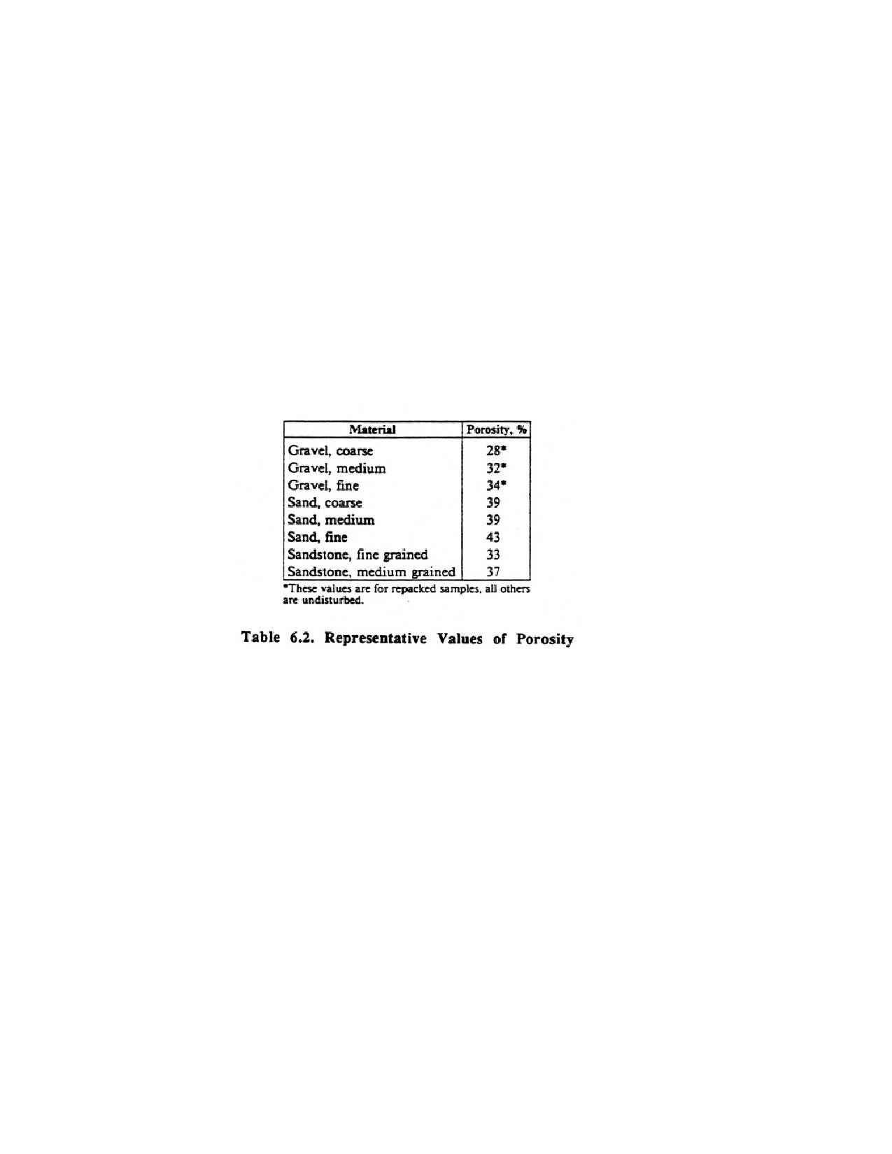
and sand and gravel deposits are presented in Table 6.2. Continuous slot screens often equal
or exceed the open area of the natural aquifer material except where unusually small
openings must be used to control fine sand. Water flows more freely through a screen with a
large intake area compared to one with limited open area. The entrance velocity through the
larger intake area is low, and therefore the head loss for the screen itself is at a minimum.
This, in turn, minimizes drawdown in the well at a given rate of pumping. The characteristics
of the continuous V-shaped slot openings are vital to successful development and completion
of a screened well. Any development method depends on having the smaller sizes of sand
and silt pass through the screen openings, which must be nonclogging and closely spaced.
Development is most effective when the screen openings are evenly spaced around the
circumference of the screen, the open area is as large as possible, and the configuration of the
slot openings allows the development energy to reach into the formation.
6.1.1. Screen Diameter
Continuous-slot well screens of welded construction are available in two series of diameters:
telescope-size and pipe-size screens. Telescope-size screens are designed to be placed in
wells by "telescoping" them through the well casing The diameters of telescope-size screens
allow them to be lowered freely through the corresponding size of standard pipe which serves
as well casing. The screens in this series are designated by the nominal diameter of the pipe
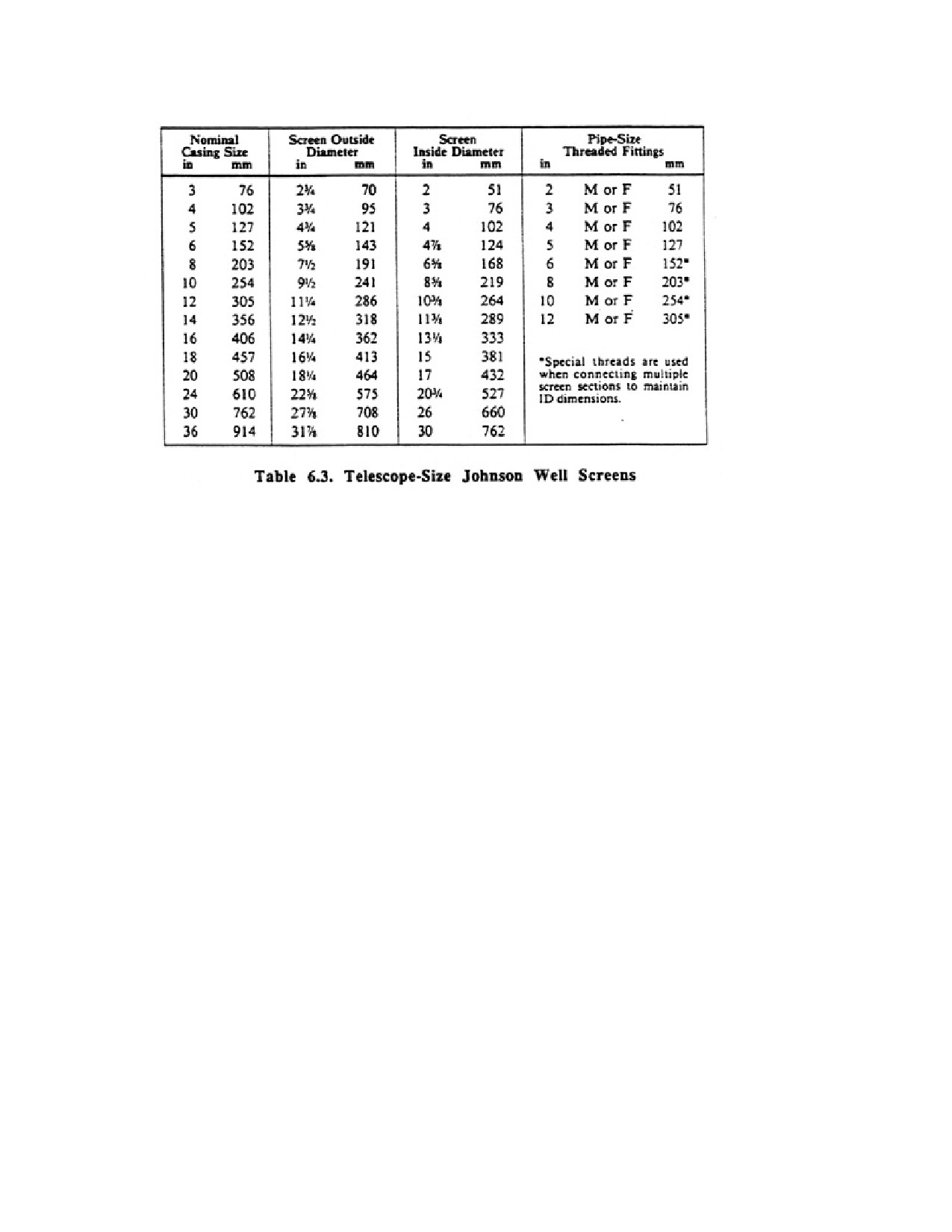
into which they will telescope. A 4-in telescope-size screen, for example, is actually 3-3/4
inches in outside diameter, which permits just enough clearance for it to pass through a Win
standard pipe. Table 6.3 gives the screen dimensions and certain other data for selected
telescope-size well screens. Lowering the well screen into place through the well casing is a
common method of installation, because it eliminates any possibility of borehole caving. A
plate is usually welded or threaded to the bottom of the screen. A bail hook can be mounted
on the upper surface of the bottom plate to facilitate lowering the screen into the well.
Threaded bottoms facilitate attachment of the hook.
Page 104 of 360
Pipe-size screens have the same inside diameter as the corresponding sizes of standard pipe.
Pipe-size screens are used when the well design specifies that the screen be attached directly
to the well casing to maintain the same diameter for the full depth of the welt
6.2. Other Types of Well Screens
Several other types of well screens exist. Some of these are mar whereas others are hand
perforated from casing or other materials. Under certain conditions, one or more of these
screens may be adequate in some geologic formations, but may provide only marginal
success under many other hydrogeologic conditions. Limited open area, poor slot
configuration, and short-lived screen material contribute to their limited success. One very
common well screen is slotted plastic pipe. Slotted plastic pipe is used lo screen wells in some
areas, particularly in clay-rich sediments (for example, clayey tills) where no aquifer zone
can be identified. Slotted plastic screens are not affected by corrosive water, are easy to
install, and are relatively inexpensive. In cold climates, some plastic materials must be
handled with care to avoid breakage. The some limitations that apply to slotted metal pipe
Page 105 of 360
also apply to plastic pipe. For example, slotted plastic screens have less than half the open
area of continuous-slot plastic screens. In addition, plastic pipe materials are from one-sixth
to one-tenth as strong as stainless steel well screens.
6 3. Well Points
Well points are made in a variety of types and sizes. The welded continuous-slot screen is
made as a weI1 point by attaching a forged-steel point to the lower end of a screen and a
threaded pipe shank to the upper end (Figure 6.3). This type of construction is the most
efficient hydraulically. The most common sizes are designed for direct attachment to either
1-1/4-in or 2-in pipe. Continuous-slot well points are constructed of either low carbon steel
or stainless steel. The sizes of openings are designated by numbers that correspond to the
actual width of openings in thousandths of an inch or the metric equivalent. Although these
units cart withstand hard driving, they should not be twisted while being driven or used in
areas where boulders or large stones are expected unless special installation methods are
used.
Another type of well point consists of a perforated brass or stainless steel jacket covering a
perforated pipe, with an intervening layer of wire mesh. The perforations in the steel pipe
core, less the obstruction of the mesh and outer jacket, constitute the effective intake area for
this type of well point. The forged-steel-point bottom has a widened shoulder designed to
Page 106 of 360
push gravel or stones aside and reduce the danger of ripping or puncturing the jacket as the
well point is being driven into the ground. The relatively low open area of this type of well
point may cause high rates of incrustation in hard waters and the bimetal construction often
leads to excessive galvanic corrosion in waters with a low pH.
Still another type of well point design is a galvanized pipe with half-moon shaped
perforations. A layer of stainless steel mesh is wrapped on a plastic pipe insert which is
slipped inside the galvanized pipe. Although the intake area of the screen is not large, the
wire mesh is reasonably well protected from rocks and stones during driving. The size of the
screen openings is designated by the mesh number, which is the number of openings per
linear inch. Common sizes are 40, 50, 60, 70, and 80 mesh.
6.4. Optimum Well Screen Open Area
The desirable percentage of open area in a well screen should at least equal the porosity of
the water-bearing sand or filter pack. Assume the sand has 30 percent porosity and the well
screen installed in the sand has 10 percent open area. The difference causes a constriction of
flow as water enters the welt This means more drawdown for a given pumping rate, because
additional head loss occurs as water passes through the screen openings. Thus, screened
wells perform best when the intake area of the screen is as great as possible for a particular
slot opening and strength requirement
For wells completed in fine-sand formations, most well screens cannot provide a percentage
of open area equivalent to the sediment porosity. The size of openings required to control the
fine sand is often so small that even the best continuous-slot screen will fall somewhat short
of matching the porosity. Porosities for well-sorted sands vary from about 20 to 40 percent. If
a No. 10 (0.010 in) slot screen is needed, the most efficient screen construction
(continuous-slot with narrowest wire) would provide a little more than 18 percent open area
If the slot is increased to No. 20 (0.020 in), the open area is 30 percent. However, many
inefficient screens have less than 10 percent open area Slotted pipe, for example, may have
as little as 2 percent open area Thus, the continuous-slot screen is the only type that can
approximate the natural porosity of well-sorted aquifer material for the full range of screen
slot size.
6.5. Sediment Size Analysis
Page 107 of 360
Selection of slot size is a critical step in assigning maximum well performance. The slot size
of the screen is based on a size analysis of the formation samples. By analyzing the
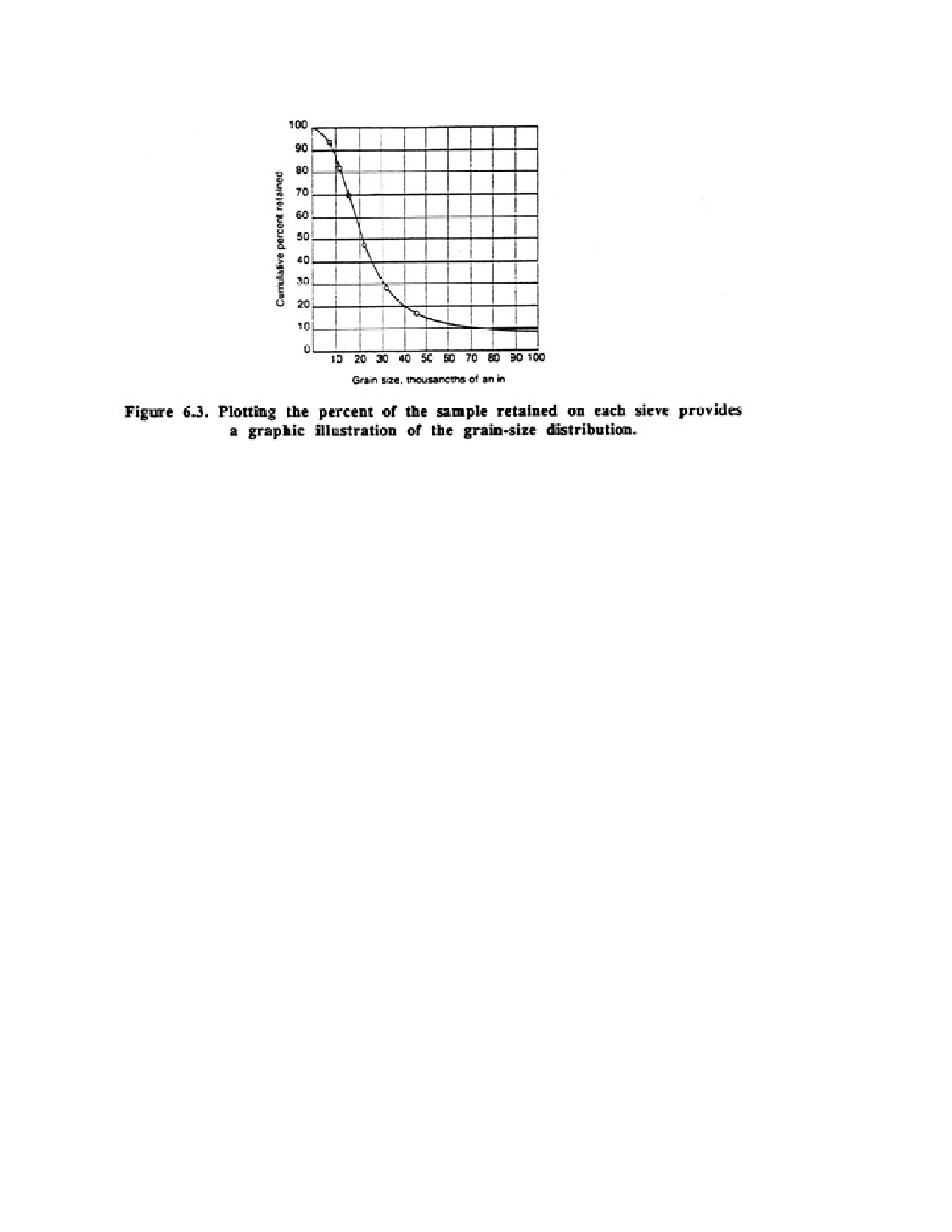
component sizes of the grains in the sample, a grain-size distribution curve can be drawn.
Several methods can be used to obtain information on the grain-size distribution. The most
widely used method involves passing the materials through a stacked set of 8-in brass or
stainless steel sieves which are shaken in a special vibration machine. During the sieving
process, each sieve filters out a certain percentage of the entire sample; the finest material
collects in the bottom pan. Plotting of these percentages (weights) of the whole sample
provides an insight into the physical makeup of the sample (figure 6.3).
Other methods to determine the grain-size distribution include sedimentation analysis using
velocity settling tubes for sediments seller than 0.003 in and automatic particle size analyzers
with computer printouts of grain size distribution data by x-y plotters. Because sieving is the
most common method used to determine the grain-size distribution, much of the discussion
which follows will focus on the correct procedures to use when sieving.
6.51. Sediment Size
In describing the fineness or coarseness of a granular material, the terms fine sand, coarse
sand, fine gravel, and other similar terms are used. Unfortunately, these terms do not apply to
specific particle sizes, which results in various scientific and engineering specialties using
different terns for sediments of the same size. Therefore, several different grain-size
classifications have been developed to define each descriptive term. Each of these systems
has been adopted in the special field where it seems to fit the best.
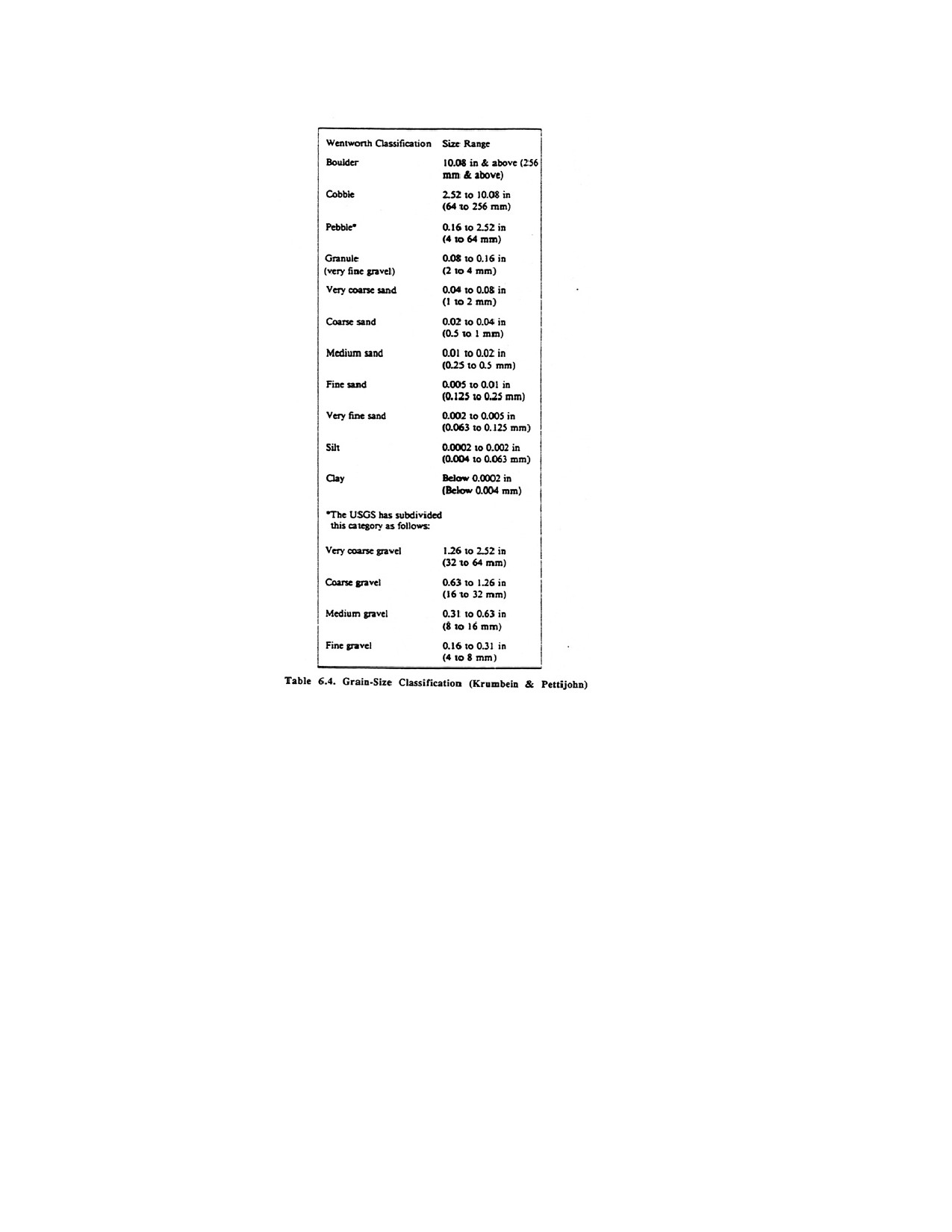
The Wentworth scale, developed in 1922, is still the basic particle size classification used in
the groundwater field. The United States Geological Survey (USGS) uses this classification
but has taken one size range, 0.16 to 2.5 in, and subdivided it into groups. The Wentworth
scale and USGS amendments are shown in Table 6.4.
Page 108 of 360
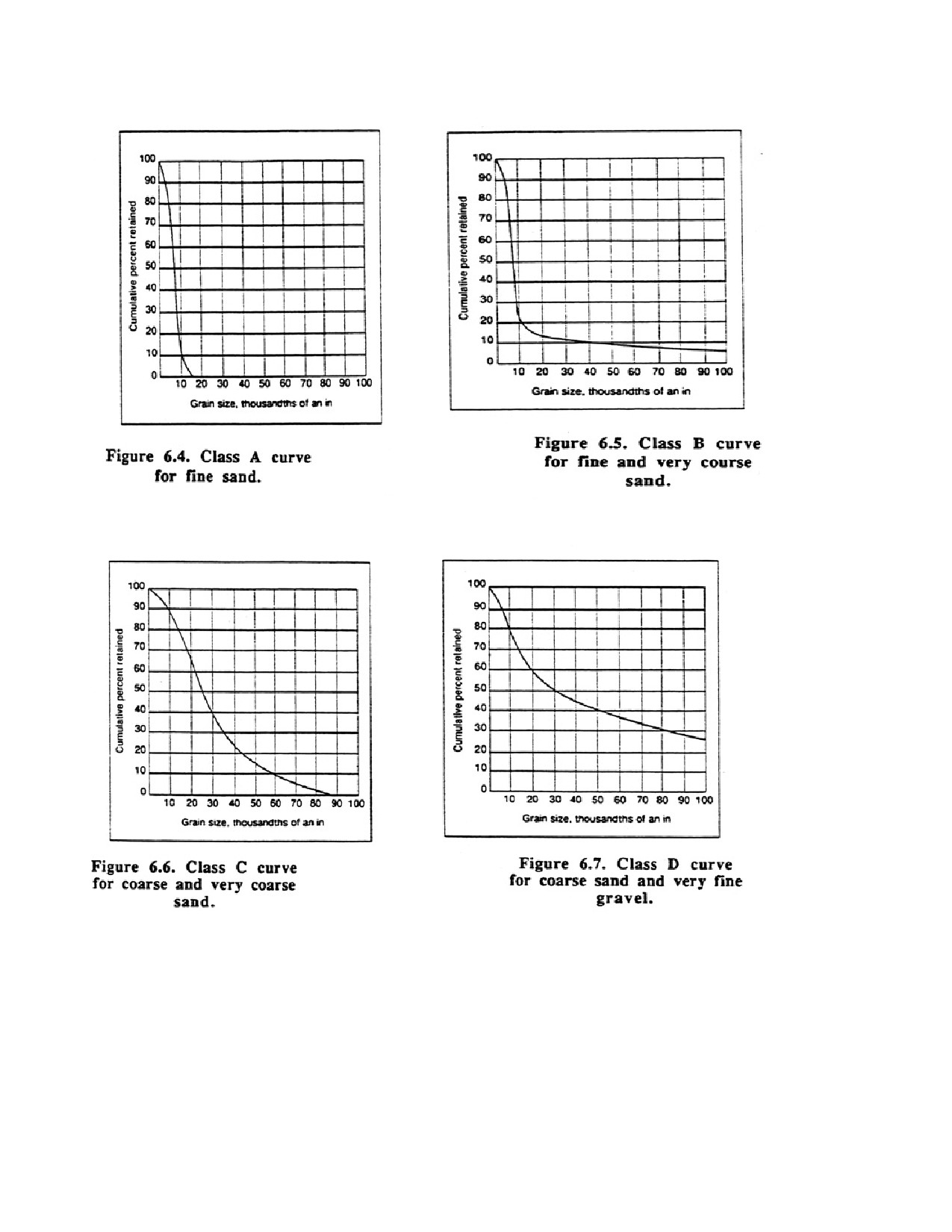
The curve in Figure 6.4 shows that the sample tested consists of medium and coarse sand,
according to the USGS classification. Applying the same system to the fo~ curves in Figures
6.5 to 6.8 gives the following descriptions:
Class A curve—fine sand
Class B curve—fine and very coarse sand
Class C curve—coarse and very coarse sand
Class D curve—coarse sand and very fine gravel
6.5.2. Slope and Shape of Curve
Page 109 of 360
The slope of the major portion of a grain-size distribution curve can be described in several
ways. One term that is used extensively is the uniformity coefficient, which was developed
by Hazen at the same time he adopted the idea of effective size. Uniformity coefficient is
defined as the 40 percent retained size of the sediment divided by the 90 percent retained
size. The lower its value, the more uniform is the grading of the sample between these limits.
Larger values represent less uniform grading. The uniformity coefficient is limited in
practical application to materials that are rather uniformly graded. It is meaningful only when
its value is less than 5. It is well suited for describing the desired uniformity of filter-pack
materials. The uniformity coefficient for the sample in Figure 6.3 is 2.9 (0.026 in divided by
0.009 in). For the Class B curve, the uniformity coefficient is 2; for the Class C curve, its
value is 3.
The grain-size distribution curves for most granular materials deposited by running water and
wave action are referred to as S-shaped curves, although this term is properly applied only to
the percent passing curves. The S-shape of the curve becomes distorted when gravel
constitutes 15 percent or more of a mixture of sand and gravel. The curve in Figure 8.5 and
the Class A and Class C ewes are typical S-shaped distributions. The Class D curve has a
"tail" of coarse material. Size distributions that result in S-shaped ewes usually represent
samples having higher porosities than are found in samples with a "tail"-type configuration.
There is yet no accurate way to calculate hydraulic conductivity directly from the grain-size
distribution curve. Many tests and research studies have been performed to find a simple
relationship between the grading of a sediment and its hydraulic conductivity, but no
dependable correlation that may be applied generally has yet been discovered Nevertheless,
with practical experience, it is possible to estimate the relative yields of different sand and
sand and gravel mixtures by careful consideration of the three factors described in this
section.
CHAPTER 7.
WATER WELL DESIGN
7.1. WELL SCREEN LENGTH
The optimum length of well screen is based on the thickness of the aquifer, available
drawdown, and nature of the stratification of the aquifer. In virtually every aquifer, certain
zones (horizons) will transmit more water than others. Thus, the intake part of the well must
be placed in those zones having the highest hydraulic conductivity. Determination of the
most productive layers can be made by one or more of the following techniques:
1. Interpretation of the drillers log and comments on drilling characteristics such as fluid loss,
penetration rate, and pulldown and chatter.
2. Visual inspection and comparison can be made of samples representing each sediment
layer. The relative transmissivity of each layer is estimated from the observed coarseness,
lack of silt and clay, and thickness of the layer.
Page 110 of 360
3. Sieve analyses can be made from samples taken from the various layers in the aquifer.
Comparison of grain-size curves can indicate the relative hydraulic conductivity of each
sample.
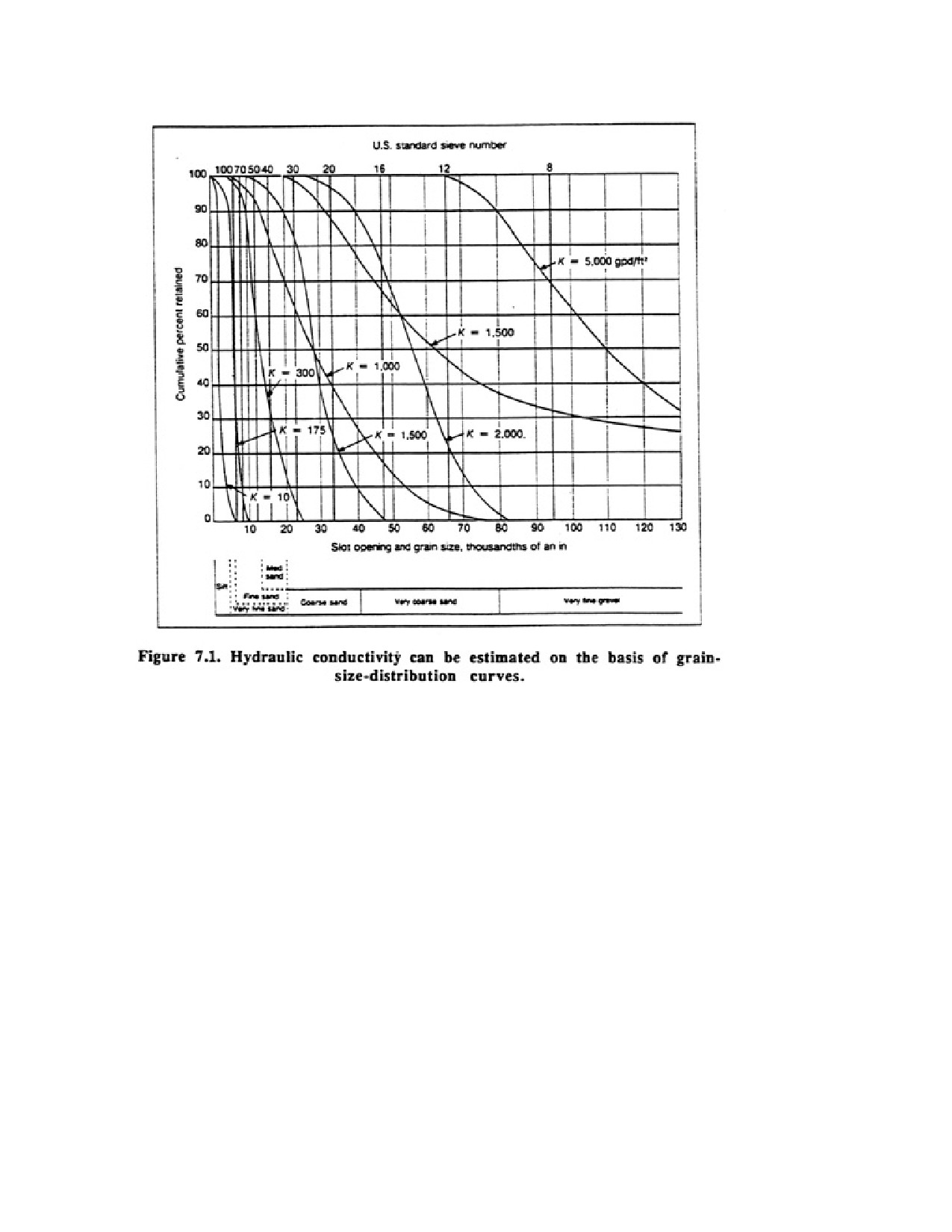
The curves presented in Figure 7.1 indicate the relationship between the grain-size
distribution of aquifer materials and the resulting hydraulic conductivity.
4. Laboratory hydraulic conductivity tests can be performed on samples that represent
individual layers of the water-bearing formation. In this test, water is caused to flow through
a sample the material. Measurements of the area through which flow occurs, the rate of flow,
and the corresponding head loss provide data for calculating the hydraulic conductivity.
Aquifer transmissivity can then be determined by adding the individual transmissivity values
for all layers of the aquifer (transmissivity equals the hydraulic conductivity times the
thickness for each layer).
5. Borehole geophysical logging techniques can help locate zones having the highest
hydraulic conductivity. Velocity meter surveys also are extremely useful
Each technique listed above provides useful information on the zones that should be
exploited. As many of these techniques should be used as possible.
Page 111 of 360
Recommended screen lengths for four typical hydrogeological situations are given below.
1. Homogeneous Unconfined Aquifer. Theoretical considerations and experience have shown
that screening of the bottom one-third to one-half of an aquifer less than 150 ft thick provides
the optimum design for homogeneous unconfined aquifers. In some cases, however,
particularly in thick, deep aquifers, as much as 80 percent of the aquifer may be screened to
obtain higher specific capacity and greater efficiency, even though the total yield is less.
A well in an unconfined aquifer is usually pumped so that, at maximum capacity, the
pumping water level is maintained slightly above the top of the pump intake or screen. The
well screen is positioned in the lower portion of the aquifer because the upper pert is
dewatered during pumping
For wells in unconfined aquifers, selection of screen length is a compromise between two
factors. On the one hand, higher specific capacity is obtained by using the longest screen
possible. This reduces convergence of flow and entrance velocity, thereby increasing specific
capacity. On the other hand, more available drawdown results from using the shortest screen
possible. These two conflicting aims are satisfied, in part, by using an efficient well screen
that minimizes the loss in specific capacity as drawdown increases.
2. Nonhomogeneous Unconfined Aquifer. The basic principles of well design for
homogeneous unconfined aquifers also apply to this type of aquifer. The only variation is
that the screen or screen sections are positioned in the most permeable layers of the lower
portions of the aquifer so that maximum drawdown is available. If possible, the total screen
length should be approximately one-third of the aquifer thickness.
3. Homogeneous Confined Aquifer. In this type of aquifer, 80 to 90 percent of the thickness
of the water-bearing sediment should be screened, assuming that the pumping water level is
not expected to be below the top of the aquifer. Maximum available drawdown for wells in
confined conditions should be the distance from the potentiometric surface to the top of the
aquifer. If the available drawdown is limited, however, it may be necessary to draw the well
down below the bottom of the upper confining layer. When this occurs, the aquifer will
respond like an unconfined aquifer during pumping
Screen lengths chosen according to these rules make it possible to obtain about 90 to 95
percent of the specific capacity that could be obtained by screening the entire aquifer. Best
results are obtained by centering the screen section in the aquifer. In the past, screens were
often interspaced with blank casing placed in the less permeable zones of the formation.
Today, however, higher water demands and lower screen costs have resulted in completely
screening most deep wells.
4. Nonhomogeneous Confined Aquifer. In this type of aquifer, 80 to 90 percent of the most
permeable layers should be screened.
7.2. DESIGN OF DOMESTIC WELLS
Many of the design requirements for high-capacity industrial municipal, and irrigation wells
also apply to domestic, farm, and stock wells. The selection of well screen openings, entrance
Page 112 of 360
velocity requirements, and recommended screen and pipe material are as important for these
wells as for high-capacity wells.
Thousands of wells are drilled every year for homes and farms where the total water
requirements may be 5 to 30 gpm. For these requirements, long screens in relatively thick
aquifers would be uneconomical. The farmer and the homeowner, however, need a
dependable water supply that can be obtained with reasonable drawdown. In these cases, a
compromise is necessary between well cost and well efficiency.
The drilling contractor must insure that enough potential drawdown is available to meet
present and future yield requirements.
It is difficult to specify exact rules for choosing the screen length for low-capacity wells. For
economic reasons, many domestic and farm wells must be constructed in less prolific
aquifers and at depths that do not provide maximum hydraulic efficiency. In general,
domestic wells should be constructed with screens 4 to 5 It long; for farm wells, the screens
should be 10 to IS R long, depending on the hydraulic characteristics of the aquifer and the
yield requirements. These recommendations apply to continuous-slot screens only. For other
types of slot configurations, much longer screens many be required. The examples cited
below demonstrate how short screens are used in typical situations.
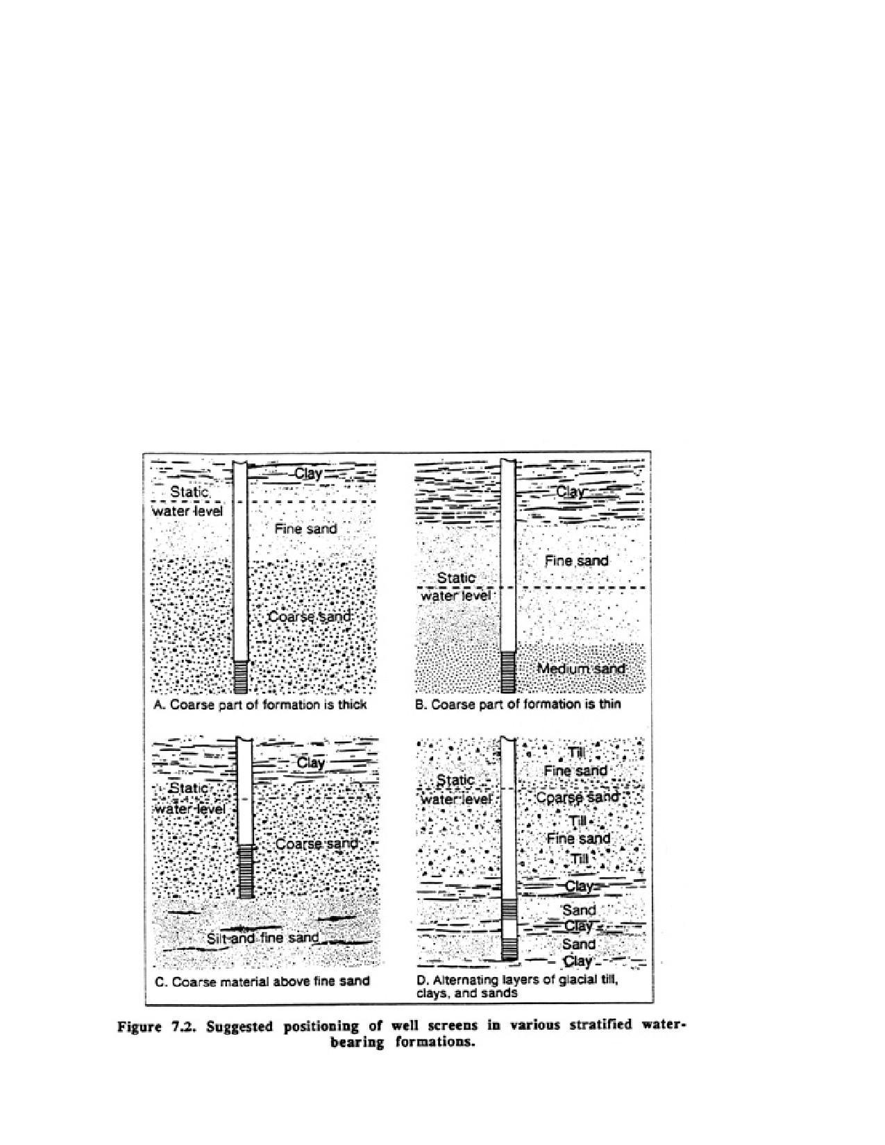
For the situation shown in Figure 7.2A, only 4 or S ft of the aquifer needs to be screened for
a domestic well because of the relatively high static water level and high hydraulic
conductivity of coarse sand. For a farm welt the screen length should be increased to 10 ft (3
m) because the required yield is usually higher. The reduction in available drawdown is not a
problem because the transmissivity of the aquifer is adequate.
For the situation in Figure 7.2B, most of the medium sand should be screened. If a screen of
this length does not provide sufficient open area for the desired yield, the screen may have to
be extended a short distance into the finer sand above, although the contribution to the yield
from the added screen footage may not be significant. In this case, sufficient drawdown is
available if the screen is lengthened.
The screen for the well in Figure 7.2C should be set at the bottom of the coarse sand layer if
adequate drawdown is available (as shown here). The length of the screen should be about
one-third the thickness of the coarse sand. Ordinarily, it would not be beneficial to extend the
screen deeper into the fine sand, because good yields from highly stratified silt/sand layers
are considerably more difficult to obtain.
In Figure MID, the hydrogeologic conditions are not as favorable. Although the static water
level is high enough to provide adequate drawdown for a farm well, the thickness of the sand
layers is limited. In fact, the two lower sand layers should be partially screened to provide
enough open area to the formation. In this case, two 3 It sections of screen are placed in the
lower portion of the deep sand formations and connected by blank pipe. The top of each
screen should be kept 3 It below the top of the aquifer to allow for anticipated sloughing of
overlying clay during development. This type of installation is relatively common in
glaciated terrains, but requires careful logging of the well by the drilling contractor.
Page 113 of 360
Although screens longer than 10 to 15 ft may not be necessary In domestic or fawn wells to
meet present yield requirements, water demands almost invariably increase with time.
Contractors should anticipate these greater demands by installing screens of sufficient length
to provide for increases in yield, because screen cost is usually a minor part of the total well
cost. The yield of E well may be increased almost in proportion to an increase in screen
length, provided the well taps water-bearing formation of reasonable thickness. For example,
doubling the screen length can, in most cases, almost double the well yield. Doubling the
diameter, however, can be expected to increase yield only about 10 percent, except when the
yield is restricted only by pump size and a larger diameter pump would increase yields
substantially.
Small wells should also be constructed with screens and casing of sufficient diameter so that
effective development methods and tools can be used Many wells are completed with 2-in
drive points driven out of Din casing Although these wells are satisfactory from a design
standpoint, they are difficult to develop properly.
Page 114 of 360
7.3. DESIGN FOR SANITARY PROTECTION
The design of a water well supplying potable water should include those features that provide
continuous sanitary protection. Contaminated water from surface drainage or low-quality
water encountered in die wed can move downward Slough the annulus between the casing
and borehole wale Thus, the annulus around the casing must be sealed. Generally, any
sealing around the well involves placing a cement grout in the annulus; bentonite is
sometimes used in place of cement.
7.4. SPECIAL WELL DESIGNS
Various design methods have developed in certain areas because of particular Hydrogeologic
conditions, the type of drilling equipment used, the availability of filter pack material, and
the economic aspects of the wells. These methods and procedures were developed because
more water was needed than could be obtained with standard design criteria and because
favorable cost/benefit ratios were realized. Although developed locally, these methods can be
used successfully in areas where similar hydrogeologic conditions exist. Several examples of
alternative well designs are described below.
Case 1
Hydrogeologic conditions: High-quality water found in sinuous, thin alluvial and
glaciofluvial deposits in river valleys. Small volumes of water also found in underlying
igneous and metamorphic rocks.
Problem: Underlying bedrock aquifers do not offer sufficient volumes of water. Alluvial and
glaciofluvial aquifers are small in areal extent and are relatively thin. These aquifers are
sustained, however, by high rates of induced filtration from nearby streams or rivers.
Solution: To pump large volumes of water at low incrustation rates, the screen slot size must
be as large as possible because the screen length is limited. This is accomplished by placing
two filter packs around a large-diameter, but necessarily short, screen segment, thereby
increasing the effective diameter of the screen. The purpose is to reduce the amount of
drawdown required to drive water into the screen by greatly increasing the porosity and
hydraulic conductivity of the material adjacent to the screen. The outer peck is selected to
control movement of the aquifer materials, whereas the inner pack retains the outer pack
material The inner pack is much larger in particle-size distribution than is the outer peck, so
the screen slot size is also much larger. In this design, the intake area of the short screen is
maximized by increasing the diameter (it cannot be lengthened), and the slot size is
considerably larger than could be achieved with a single pack. Thus, high yields are
obtainable at low incrustation rates from short screen sections when they are located in
highly permeable sediments near sources of recharge.
Case 2
Hydrogeologic conditions: High quality water exists in near-surface thin sand layers that are
underlain by thick clay layers. The underlying bedrock contains only low quality water that is
not suitable for potable supplies.
Page 115 of 360
Problem: Yields from conventional wells are insufficient for even domestic use because the
aquifers are thin. Water tables fall enough during fall and winter to cause wells to go dry.
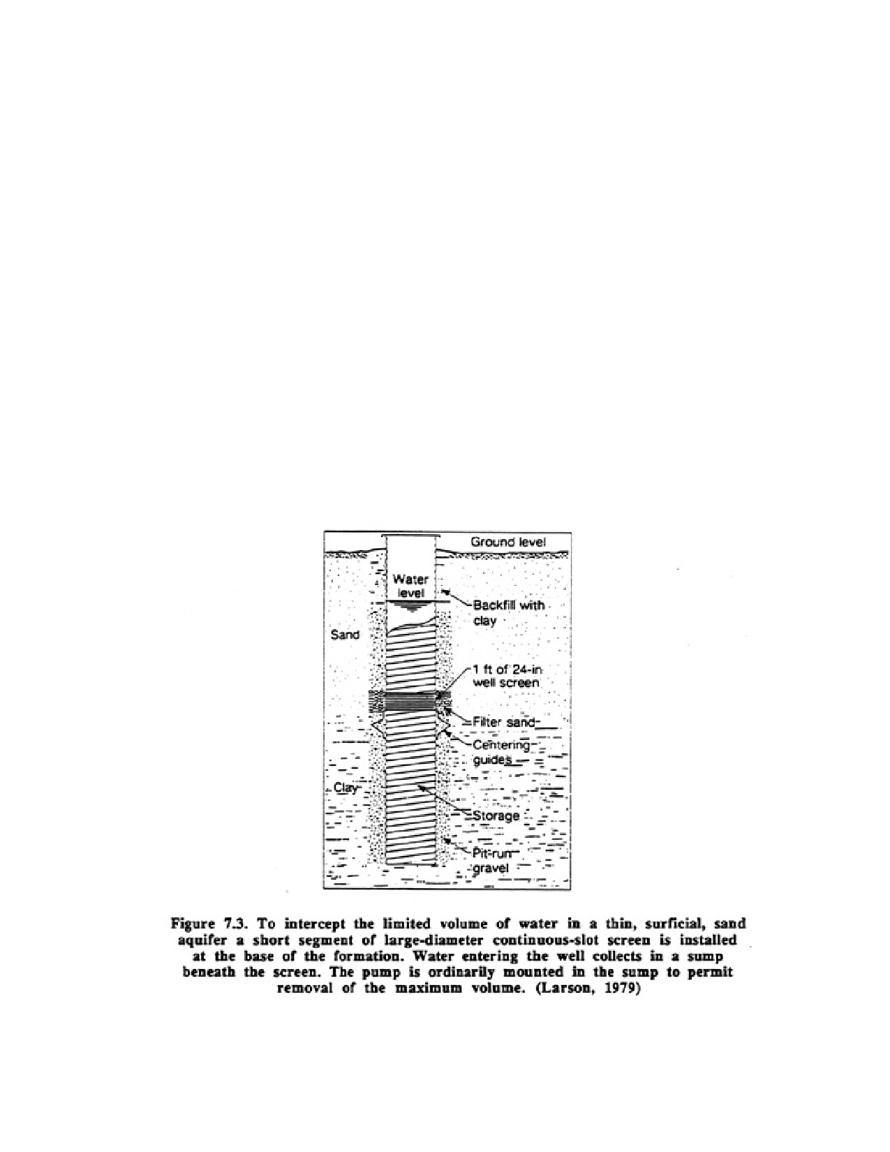
Solution: A 24 to 48-in borehole is drilled through the overlying sand layer into the clay,
usually by bucket or earth auger. The borehole is kept open below the water table by keeping
it filled with water and by adding drilling fluid additives to reduce fluid losses. A 1- to 2-ft
length of continuous-slot screen is installed in a string of casing so that the screen is placed at
the bottom of the aquifer (Figure 7.3). The pump intake is placed in casing (sump) that
extends beneath the screen. During periods of nonpumping, water cascades into the sump,
which acts as a reservoir. The bottom of the casing stung is usually sealed with cement or a
steel plate. The screen is filter packed, but the annulus above and below the screen may be
filled with gravel, sand, or clay. Yields from this type of installation will vary according to
the fineness of the sand layer and the depth of the water table, but sustained yields are usually
much greater than can be expected from a typical well installation and are generally adequate
for most domestic water demands.
Case 3
Hydrogeologic conditions: Extremely small volumes of water are found throughout thick,
dirty, fine-grained sand/silts/one sequences that are buried at depth and may be under
confined pressures.
Problem: It is not economical to set large-diameter screens because of the potentially small
yields and the difficulty in identifying the most productive zones.
Page 116 of 360
Solution: To obtain a reasonable yield, a string of 2-in continuous-slot screen, commonly 40
to 100 ft long, is installed through the full thickness of the formation. The screen may be
filter packed or the annulus filled with a formation stabilizer, depending on how well the
aquifer materials are cemented together. Anticipated yields mom this type of screen
installation are usually 40 to 60 8pm.
Case 4
Hydrogeologic conditions: In coastal areas with high annual rainfall, a thin 2- to 3 ft veneer
of fresh water sometimes overlies saline water. The fresh water is of high quality, but can be
easily contaminated with salt water unless pumping rates are kept low.
Problem: Ordinary well designs win cause salt water to cone upward during pumping,
leading to contamination of the overlying fresh water.
Solution: To obtain reasonable volumes of high quality fresh water, it is necessary to
eliminate the upconing effect. This is done by installing several widely spaced wed points
that are then manifolded together and pumped by suction lift. The points are pumped lightly
to minimize pressure reductions in the vicinity of the points. The water is stored in a 500-gal
tank. A separate pump is used to move the water from the tank to the house system. With
conservative use, a single tank may provide enough water for several days for a family.
CHAPTER 8.
INSTALLATION AND REMOVAL OF WELL SCREENS
Well screens are required in all unconsolidated and most semiconsolidated formations, and
occasionally in consolidated rock Many different screen installation methods are used,
although certain procedures may be more practice or more economical in certain areas or
when particular drilling rigs are used The exact procedures to be followed when installing a
well screen depend on the nature of the aquifer materials, the method used to drill the well,
the dimensions of the borehole, the hydraulic conditions in the aquifer, and the casing and
screen materials. Well completion steps that are done during installation or immediately
thereafter include installing the filter pack materials grouting the casing, and developing the
well. The most common and successful screen installation methods are described below.
8 1._PULL-BACK METHOD
Before the recent increase in the number of direct rotary drilling rigs, the pull-back procedure
was used in most wells. It is a safe method of installation that reduces problems resulting
from heaving sediment, sloughing of the borehole walls because of swelling clays or
insufficient hydrostatic pressures, and setting the screen at the wrong depth. The pull-back
method also permits the screen to be removed and replaced if necessary, without disturbing
the sanitary grout seal outside the well casing. The cost of pulling, cleaning, or replacing the
screen is usually small in comparison with drilling a new well. The pull-back procedure is
particularly suited for wells drilled with a cable tool rig and with air rotary rigs equipped with
casing drivers, although some direct rotary drillers use it as their standard method of
installation for shallow wells.
Page 117 of 360
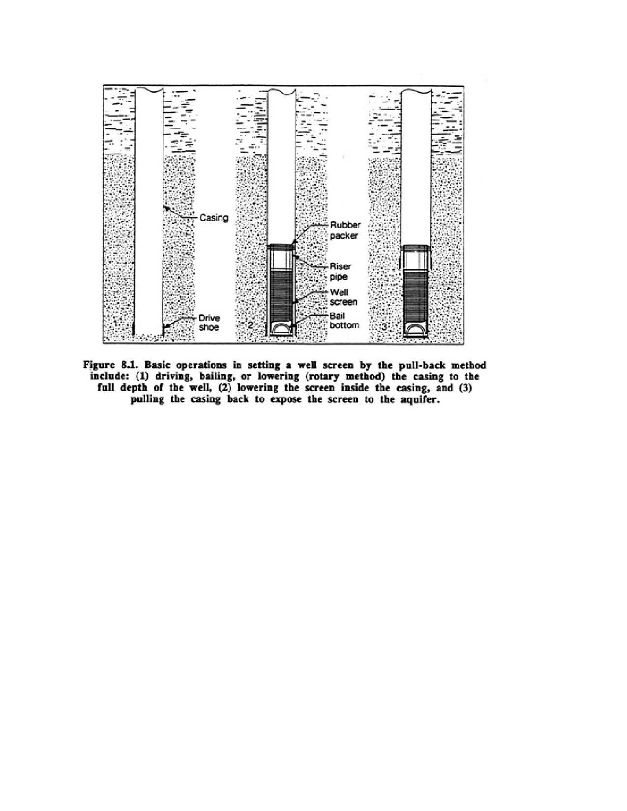
The pull-back method involves insuring the casing to the full depth of the well, lowering
(telescoping) the well screen inside the casing, and then pulling back or lifting the casing far
enough to expose the screen to the water-bearing materials (figure l0.l ). The casing must be
strong enough to be set the full depth of the well and then be pulled back the length of the
screen.
Telescope-size screens are designed for use in the pull-back method. As the term "telescope"
implies, the screen is constructed so that it will telescope through standard pipe of the
corresponding size, allowing installation of the largest diameter screen possible for a given
casing diameter. Occasionally, pipe-size screens that are one or more diameters less than the
casing may be telescoped through larger diameter casing
8.1.1. Packers
A special fitting is required to provide a sand-tight seal between the top of the telescoped
screen assembly and the casing. Two types of packers were commonly used: neoprene rubber
(often called K packers) and lead. Lead is no longer acceptable. The packer is attached
direcdy to either the top of the well screen or the top of a riser pipe.
A rubber packer is constructed of flexible neoprene rubber attached to a steel coupling and fits
tightly in the casing, sealing the casing to the screen. The use of this type of packer has grown
rapidly because no expansion of the packer is required. Frequently two or more packers are
used in series to eliminate problems caused by small deviations in the dimensions of the
casing or packer resulting firm improper handling. Furthermore, multiple rubber packers are
recommended for screens set at depths exceeding 300 ft because the rough inner surface of
the casing, often caused by weld slag or beads in welded casing, can damage the rubber lips
of the packer. Lubricating the lips of the rubber packer with petroleum jelly will reduce
damage when the screen is lowered into the casing.
Page 118 of 360
The packer is ordinarily attached to a riser pipe and expanded in the casing The top of the
packer is fitted with a left-hand thread so the drill pipe can be disengaged mom the packer.
Inflatable packers generally have larger expansion ratios than do casing hangers. The packer
is inflated by injecting gas, water, or a solidifying liquid Thus, the packer can be used for a
short time and then retrieved or installed permanency. Some fixed-end packers can be
inflated to two times the uninflated diameter, but are generally designed for lower pressure
applications than are sliding-end packers. Sliding-en] packers are used where the differential
pressures range mom 200 to 2,000 psi or more. Inflatable packers are useful for effecting
casing repairs, pumping tests of isolated zones in the borehole, hydrofracturing, and injecting
water and gases.
Occasionally, a screen much smaller in diameter than the casing is used. For example when a
high yield is anticipated, a relatively large diameter casing may be needed to accommodate
the pump bowls. A large diameter screen may not be needed or practical, however, because
the open area of a smaller diameter screen is sufficient to accommodate the expected yield at
properly designed entrance and uphole velocities. A special cone adaptor is then used to
connect the smaller diameter screen to the larger packer needed for the casing. The packer
and cone adaptor are attached to the screen before installation.
8.1.2. Setting the Screen in Wells Drilled by the Cable Tool Method
It is important to control sediment movement into the bottom of the casing because the
screen should be set as close as possible to the designed depth. This is particularly important
Page 119 of 360
if the screen has been designed with several slot sizes corresponding to individual sediment
layers, or if blank sections have been placed between screen sections. If there is difficulty in
keeping sediment from heaving inside the casing, the casing should be filled with water.
Fluid losses may be controlled by using prepared drilling fluids. To keep confining pressures
in the aquifer under control, the drilling fluid may be weighted with special high-density
materials or salt. Sudden vertical movement of tools in the casing also increases the
likelihood of heaving problems. Therefore, bailers should be operated slowly to reduce
pressure differences at the bottom of the borehole.
After the casing has been driven to the proper depth, any sediment that has entered or settled
within the casing should be removed carefully. After all sediment has been removed from the
casing, the driller must be sure the casing can be withdrawn. If it cannot be withdrawn, the
drive shoe is Cut off with an inside casing cutter to reduce resistance, and the casing is pulled
back a few inches. The screen is then lowered to the bottom of the welt. Several devices can
be used to lower the screen: bail and hook, eccentric clevis (offset latch), eyelet screws
mounted in packers, casing lugs (bayonet type), and wash-down bottoms.
If the screen is made in two or more sections, the bottom section is lifted by a rope clamp or
hitch and suspended inside the casing by a pair of casing clamps or elevators. The next
section is then threaded or welded to the top of the first section
If the depth to water is less than 50 ft. short, small diameter screens may be installed by
dropping them inside the casing. If rubber packers are used, screens 4 to 6 inches in diameter
generally will not drop and must be pushed into place, whereas screens 8 in and larger will
drop because of their weight. Careful measurements must be kept so the driller will know
that the screen is set at the correct depth in the aquifer.
The drill string or a weight attached to the sand line should be placed on the bottom of the
screen while the casing is being pulled back This provides enough weight to keep the screen
on the bottom, and the tension in the sand line serves to verify the exact position of the
screen during the procedure. If weight is not applied to the screen, any heaving of the
formation will force the screen upward at about the same rate that the casing is pulled back.
The casing can be pulled back by one of several methods. Under ideal conditions where the
earth materials have not collapsed tightly around the casing, it can be pulled with the casing
line on the cable tool drilling machine. Greater lifting force can be obtained by using a block
and tackle attached to the casing line. If the casing cannot be withdrawn by the casing line, it
may be pulled by jarring with the drilling tools with fishing jars attached, or a bumping block
or drive clamps. Mechanical or hydraulic jacks may also be required to provide the necessary
lifting force. If so, a pulling ring or spider with wedges or slips is used to grip the casing For
long casing strings, a vibration hammer is effective in overcoming the skin friction between
the casing and formation. Although the cost of this procedure may be high when compared
with other methods, it is sometimes the only method powerful enough to withdraw casing
As the casing is being pulled back to expose the screen in the water-bearing formation, depth
measurements to the screen are taken. If no riser is attached to the screen, the casing should
be pulled back so that the packer is about 12 in above the bottom of the casing. The screen
can be fully exposed beneath the casing if a riser pipe is attached to the top of the screen.
Page 120 of 360
8.1.3. Setting the Screen in Wells Drilled by the Rotary Method
When screens are installed in rotary-drilled wells, the pull-back method should be selected if
caving conditions exist or lost circulation is a problem. Drill pipe should be withdrawn
slowly from the hole after the maximum depth has been reached to eliminate heaving caused
by suction. The presence of the drilling fluid column will usually control caving problems,
except in relatively shallow, unconsolidated glacial or alluvial sediments. Natural compaction
of these sediments is not great, and in confined aquifers the material is close to a condition
where any suction or other disturbances in the borehole will cause the sediment to "run"
toward the low-pressure (suction) zone.
Setting the casing to the bottom of the hole and then pulling it back may appear to be extra
work, but this operation prevents serious problems arising from premature caving which can
occur when the drilling fluid viscosity is reduced prior to development. The protection given
by the casing is particularly important if a delay is anticipated between drilling and screen
installation. During this period, a momentary loss of drilling fluid may cause partial collapse
of the borehole.
After the casing is placed in the open borehole, any cuttings that settle inside it are carefully
cleaned out. The screen is then lowered to the bottom through the casing and the casing is
pulled back to expose the screen. After the casing is pulled back, it must be held in place until
the fannation has caved around it during development or until the annulus has been backfilled
or grouted.
For wells drilled with air rotary machines equipped with casing drivers, two setting
procedures can be followed, depending on the stratigraphy. In heaving formations, the casing
is usually sunk to the top of a clay layer under the aquifer, the screen set within the casing,
and the casing pulled back. If no clay exists and heaving is a problem, it may be necessary to
change from air-based to water-based drilling fluids to control fluid pressures in the
formation so the screen can be set. Occasionally, stiff foam may be enough to control the
formation. In thin aquifers, it is also extremely important that the switchover be
accomplished before the borehole is over-excavated. Excessive excavation may cause
collapse of weaker overlying sediments, which may destroy the hydraulic characteristics of a
thin aquifer in the vicinity of the well. Once heaving has been controlled, the casing can be
cleaned by circulating water-based drilling fluids. The screen is then installed and the casing
pulled back
8.2. OPEN-HOLE METHODS FOR SCREEN INSTALLATION
8.2.1. Double-String Installation
Use of the pull-back method in rotary drilled wells has declined in favor of open hole
methods. A common procedure for installing screens in high-capacity industrial and
municipal wells is described below. Because this is only an example, not all alternative
methods for individual steps are included; however, other procedures are presented later in
this chapter.
Page 121 of 360
A typical procedure for installing screens in high-capacity wells includes the following steps:
1. Drill a small-diameter test hole at the chosen site, keeping a detailed drilling log and
collecting samples at specific intervals. Samples are taken at each formation change and
every 5 to 10 ft. depending on the formation thickness and well depth.
2. Conduct geophysical logs (typically SP, resistivity, natural gamma ray, and hole caliper) in
the test hole and determine which aquifer or aquifers are to be screened. Occasionally,
side-wall cores are taken to verify the type of formation and its hydraulic characteristics.
3. If more information about the aquifer is needed, such as chemical quality or productivity, a
2- to 5-in screen is-installed in the desired zone and test pumped.
4. After the production zone is chosen from an analysis of the cuttings, driller's logs,
geophysical logs, and pumping test data, samples are analyzed and the correct screen-slot
openings are determined.
5. If a test well has been drilled, the screen and casing are pulled and the test hole is then
used as a pilot hole for the production well. In uniform geologic conditions, the test hole is
often left as an observation well and the production well is drilled a suitable distance away.
The test hole can also provide make-up water for use in drilling the production welt
6. An open hole is then drilled down to the top of the aquifer to receive the casing. The hole
diameter should be large enough to allow space in the annulus between the casing and the
hole for a minimum grout thickness of 2 in.
7. The casing is set in the hole. Generally, a drillable grout shoe (plug) constructed of cast
aluminum or cement is installed on the bottom of the casing The shoe allows the grout to be
pumped through the bottom of the casing and should be used on the casing to insure proper
centering
8. The casing is then grouted. At least 24 hours should be allowed for the grout to set.
9. Any extra grout in the casing and the drillable shoe is next drilled out, but the aquifer is not
penetrated. At this point, all drilling fluid used to drill the grout should be replaced with clean
drilling fluid or water if practical. This is an important step; if the grout-contaminated fluid is
used to drill the aquifer, it may seal some of the formation and be difficult, if not impossible,
to remove from the formation. It may also have an adverse effect on the physical
characteristics of the drilling fluid.
10. If the well is to be naturally developed, the aquifer is drilled with a bit that is slightly
smaller than the inside diameter of the casing If the well is to be filter packed and the
diameter of the completed borehole is too smn11 to accommodate a proper thickness of filter
pack between the screen and formation, the aquifer may be underreamed to obtain a 3 to 8-in
annulus.
11. A suitable length of riser pipe should be used on top of the screen. If there is to be blank
pipe between the top of the screen and the bottom of the casing and the well is filter packed,
Page 122 of 360
a 5-ft length of pressure-relief screen should be included in the riser pipe stung and set at the
bottom of die casing (pressure-relief screens are discussed in the filter-pack section).
12. A screen is then telescoped through the casing into the open hole by an offcentered latch
hook, bail hook, or left-hand-threaded fittings attached to the plate bottom of the screen or to
the top of the riser pipe. The last method is the surest way to position the screen; but in deep
holes where the drill pipe exerts high pressure on the threads, the drill string should be held
back or a slip section should be used to reduce the weight on the threads while disengaging
She drill pipe from the screen. Sometimes a fin (piece of flat metal) is welded to the side of
the screen bottom plate to prevent the screen from turning when unthreading the drill pipe.
Metal bars or other attachments welded underneath the bottom plate will also prevent the
screen from turning. If the well is to be filter packed, it is recommended that one centralizer
be attached near the bottom of the screen and another near the top. For screens of less than
200 ft. centralizers should be spaced every 20 It; for economic masons, centralizers are often
spaced at Soft intervals on screens over 200 ft.
13. If it is anticipated that fill or other borehole material may prevent the screen from
reaching the desired depth, a self-closing bottom fitting with internal left-hand threads can be
mounted in the screen bottom plate to wash the screen into place. A wash pipe is attached to
this fitting and can be used to set the screen. A washbowl bottom provided with a slip-socket
wash fitting is sometimes mounted on the bottom of the screen but is not used to set the
screen. Instead, these fittings are useful in displacing drilling fluid from the borehole, thereby
aiding development. The displacing fluid, often clear water, is directed through the
wash-down bottom to remove the drilling fluid from the hole. If an open-bottom screen is
used, cement grout can be used to plug the bottom.
14. After the screen is set, the well may be naturally developed or filter packed. If the well is
to be naturally developed, the formation is induced to cave around the screen by reducing the
hydrostatic pressure in the borehole, by either thinning the drilling fluid or lowering the level
of the drilling fluid in the borehole. The setting tool is then removed and the driller begins
development.
If the well is to be filter packed, the setting tool is left in place while filter pack is introduced
into the welt A plug can be used to temporarily close the top of the screen during filter
packing. After the filter pack is in place, the setting tool or plug is removed and the well is
developed. Normally no packer has to be installed if the riser pipe is lapped 50 ft or more
into the casing and a pressure relief screen is installed.
8.2.2. Single-String Installation
In most small-diameter, rotary-drilled wells completed in unconsolidated sediments, the
screens are attached directly to the bottom of the casing. Screens that are smaller in diameter
than the casing can be welded or threaded directly to the casing by mounting a cone adaptor
or flared weld ring to the top of the screen. Screens that are the same size as the casing can be
welded or threaded directly to the bottom of the casing.
The casing and screen are then set in the hole and the drilling fluid is thinned. If the drilling
fluid is not thinned, the fluid may not enter the screen as it is lowered into the borehole. High
differential pressures can then be created, which may be sufficient to collapse the screen.
Page 123 of 360
Under these conditions, it is prudent to fill the screen with water when it is placed in the
borehole. For naturally developed wells, the formation is induced to cave in around the
screen and casing immediately after the screen is set. When wells are filter packed, the pack
material is placed before the formation is induced to cave.
To prevent clay-rich material above the aquifer from sloughing next to the screen ding
natum1 development, a formation stabilizer is often instated. The formation stabilizer holds
the clay in place until the materials cave against the stabilizer. The size gradation of a
stabilizer should be similar to the formation material or a little coarser. In most cases,
however, a formation stabilizer is not needed if the borehole is only slightly larger than the
screen and the top of the screen is placed 3 ft or more below any clay zone.
8.3. FILTER PACKED WELLS
Many wells drilled by cable tool or rotary methods are designed for a filter pack, thereby
altering the screen installation process. Filter-packed wells differ from naturally developed
wells in that an envelope of specially graded sand or gravel is placed around the well screen
to a predetermined thickness. This takes the place of the graded zone of permeable material
that is produced by the natural development process. Both types of wells, when properly
constructed, are efficient and stable. The geologic conditions, availability of suitable filter
peck materials, drilling method, and type of screen determine whether a filter pack should be
used.
The thickness of the filter pack is a primary factor in the effectiveness of the development
procedures taking place at the interface of the pack and formation. The minimum practical
thickness for the pack is 3 m. kilter packs thicker than 8 in are not recommended, because the
effectiveness of the development procedures may be impaired
8.3.1. Selection and Placement of Filter Pack
It is important to select a filter pack that will not segregate, because sand pumping can result
if fine and coarse particles become separated during placement. It can be demonstrated that a
round particle of a given size and density falls through water four times faster than a round
particle half as large and with the same density. If filter pack material that is uniformly
graded from 1/16 in to 1/8 in is allowed to fall through water as separate grains, the 1/8-in
grains will reach the bottom of the well in one-fourth the time required for the 1/16 in grains.
Thus, well-sorted filter peck material is less apt to segregate than is pack material with a
wide range of particle sizes. Sand and gravel mixtures with uniformity coefficients greater
than 2.5 are difficult to place without undesirable separation of coarse and fine fractions. All
filter pact; materials should be treated with a bactericide, usually chlorine, before placement
to insure that the well does not become contaminated. All water used in the filter peck
operation and any tools or pieces of installation equipment should also be treated with a 50
mg/l free-chlorine solution before use. Whenever possible, the drilling fluid should be
thinned before placing the pack material.
Use of a tremie pipe to install the filter pack will minimize the tendency for particle
separation and bridging, this is the preferred method for filter pack placement, especially for
packs with high uniformity coefficients. A string of 2-in or larger pipe is lowered into the
annular space to be filter packed. The filter peck material is fed into a hopper at the well
Page 124 of 360
head. A liberal supply of water should be introduced with the filter pack to help prevent
bridging of the material in the pipe. A typical ratio of water to pack material is 5 to 10 gal for
each 1 ft3 of pack material when a 2-in tremie pipe is used. The tremie system is practical for
placing the filter pack in shallow to moderately deep wells (to 2,000 ft). In some cases, filter
pack material may be pumped through the tremie pipe along with the water stream instead of
being driven by gravity.
During installation of the pack the tremie pipe is raised periodically as the filter material
builds up around the well screen. The tremie pipe or a weighted line inserted through the
tremie can be used to feel the top of the filter pack and to measure the depth to the pack as
the work progresses.
Direct circulation of clean water can also be used to reduce bridging problems.
8.3.2. Filter Pack Procedures for Wells
8.3.2.1. Drilled by the Cable Tool Method
Several different casing arrangements may be used for filter pecking wells drilled by the
cable tool method In one type of installation, the screen is connected to an inner casing,
centered in a larger borehole, and surrounded by filter pack material The inner-casing will
become part of the completed well structure and may accommodate the pump. In deep well
installations, the inner casing may not extend all the way to the ground surface. A
large-diameter outer casing is first set to the full depth of the well. An inner casing and well
screen are then centered in the outer casing, using centering guides. The selected filter
material is placed in the annular space around the screen and extended high enough above the
screen to accommodate settlement of the filter pack after the outer casing has been pulled
back. The filter pack material should extend above the top of the screen about one-fourth the
screen length.
The pack is usually placed in stages as the outer casing is pulled back. Dive feet of filter pack
material should be maintained above the screen as the casing is withdrawn. During
withdrawal, depth to the top of the filter pack must be monitored carefully by a sounding line
or tremie pipe to insure that the level never drops below the outer casing. The driller must be
careful, however, not to overfill the annulus during withdrawal because a sand lock may
develop between the outer casing and screen.
After the filter pack is installed, development work is continued to remove fine sediment
from the filter pack and to clean the contact surface between the filter pack and the
formation. As development proceeds, some settlement of the filter pack will occur and more
filter pack must be added to keep the level above the screen. After development, the annular
space above the filter pack should be sealed by bentonite pellets or cement grout. The outer
(surface) casing may be removed or left in place.
8.3.2.2. Filter Pack Procedure for Wells Drilled by the Rotary Method
In most rotary-drilled wells, the screen and casing are placed in the borehole as a unit. The
screen may be the same diameter as the casing or slightly smaller. Centralizers are generally
attached every 20 ft on the screen body and every 40 ft on the casing. The casing should be
Page 125 of 360
held in tension while the drilling fluid viscosity is reduced as much as possible without
allowing collapse of the well bore. Thinning the drilling fluid reduces development time,
minimizes flotation effects, and increases settlement rate for pack materials. Filter pack is
placed by tremie pipe or ocher means into the annulus around the screen and usually extends
some distance above the top of the screen. Kilter pack material should be added as required
during development. After development and backfilling of the borehole, the tension on the
casing and screen is released.
8.3.3. General Guidelines for Installing Filter Packs
For filter pack installations, the pack should extend at least 25 percent of the screen length
above the top of the screen. For example, a minimum of 50 ft of filter pack should be
installed at the top of a 200 ft screen to provide an adequate reservoir. The top of the riser
pipe should be well above the top of the filter pack or outer casing bottom, especially if no
packer is used at the top of the riser pipe.
8.4. INSTALLATION OF PLASTIC SCREENS
More plastic materials are now being used for well screens, especially in smaller diameter
wells. Plastic materials have predictable physical limitations, but when selected and used
properly they provide wells with adequate structure strength, good hydraulic characteristics,
and long life. For depth settings exceeding 300 ft. the screen manufacturer should be
contacted for recommendations concerning wall thicknesses.
Plastic screens can be set in many of the came ways as steel materials, but plastic does not
have the inherent strength of steel and special care must be taken during installation and well
completion. In addition, unlike steel, plastic casing may be buoyant when placed in the welt
depending on the depth to the water table and the density of the drilling fluid. Thus, setting
procedures may have to be modified. It was originally felt that plastic screens would be used
only by rotary drillers and be attached directly to plastic casing. Today, however, plastic
screens are being installed with steel casing, and steel screens with plastic casing, by both the
telescope and the direct-attached methods in rotary drilled holes.
In the past, several plastic materials were used in a variety of different wall thicknesses and
schedule numbers. Currently, PVC material constructed to Schedule 40, 80, or SDR-21
specifications are becoming the most common plastic materials used in water wells. A wide
variety of standard end fittings are available for all types of plastic pipe. Because plastic pipe
has standard outside dimensions, end fittings built by different manufacturers are generally
interchangeable. There may be extremely small differences in dimensions, however, so for
best results and where maximum performance is required, it is advisable to use pipe fittings
and pipe from the same manufacturer. PVC fittings are useful in attaching PVC to steel, or
vice versa Fittings such as male adaptors, female adaptors, reducers, and slip couplings are
available to fit any threaded fitting on the market.
8.4.1. Telescope Installations
Plastic screens can be telescoped through plastic or steel casing, but the varying inside
diameter of plastic casing (depending on schedule or SDR number) may cause some
problems in obtaining the best fit between packer and casing. Rubber packers are typically
Page 126 of 360
used, but because the outside diameter of the rubber sealing ring is constant the fit may be
either tight or loose, depending upon the wall thickness of the plastic casing. For example, in
Din pipe, there is a Q046-in difference in inside diameters between Schedule 40 and SDR-21.
Although the difference in diameter is small, it could cause serious sand pumping in a well
completed in fine sand.
Even though plastic-based rubber packers are available, the drilling contractor should make
sure that the packer is suitable for use with the particular plastic pipe being installed.
8.4.2. Setting Screens in Open Boreholes (Direct Attached)
Perhaps the simplest method of installing a plastic screen is to attach the screen directly to the
canny and then lower the entire assembly into the borehole. Screens can be attached to casing
by couplings that use solvent-welding procedures, adaptor rings that are fastened to the
casing, special locking couplings, and threaded connections.
After the casing and screen have been set in the hole, the screen may be filter packed and the
annular space above the pack then backfilled as far up the hole as possible. Placement of
backfill material prevents sudden slumping of the borehole walls before or during
development. The borehole should be backfilled carefully when plastic casing or screen are
used, because plastic casing does not have the collapse resistance of steel casing
Bentonite can be placed in the annulus above the fill material. The casing is then grouted in
place with a neat-cement mixture, above the backfill and bentonite materials. The curing
temperance of the cement must not be so high that the casing deforms.
The use of plastic casing and screens for completing wells in consolidated rock with overlying
unconsolidated materials requires special techniques. When steel casing is used, a drive shoe
is normally seated in the rock and open-hole drilling is continued through the consolidated
aquifer. Because plastic casing cannot be driven, however, special packers are used to seal
the casing to the rock.
When using plastic materials, hydrostatic pressures exerted on both casing and screen must
be kept at a minimum during development. Development should begin slowly and gently
until all drilling fluid is removed from the annulus around the screen and water is flowing
freely into the screen. The casing and screen should never be "blown dry" with an air
compressor. If compressed air is used for development, start the development process well
above the screen and at first remove only small quantities of water.
8.5. OTHER METHODS
8.5.1. BAIL DOWN PROCEDURE
Under some conditions, it may be impossible or undesirable to pull back well casing to
expose the screen. For example, side-wall friction on casing by subsurface materials may
require too much pulling force, or movement of the casing may disturb the sanitary seal
around it. In other situations, the screen cannot be set by direct-attached methods because the
static water level may be so high and the aquifer materials so loose that the borehole may not
stand open. In theses cases, the bail-down method of setting well screens may be used. The
Page 127 of 360
objective of the bail-down method is to remove sediment from below the screen so the screen
will settle.
In the bail-down method, the casing is generally set before the bailing process can begin.
When drilling by the rotary method, the casing must be fixed in a permanent position by
grouting or some other sealing method. If cement grout is used, the plug is drilled Out of the
lower end of the casing before starting the baildown procedure. When drilling by the cable
tool or casing-driver methods, the casing is usually held firmly by side-wall friction.
The well screen, fitted with a bail-down shoe or an open sleeve at its Iowa end, is telescoped
through the casing. A riser pipe may be welded or threaded to the top of the screen. If a bail-
down shoe is used with special connection fittings, the screen is suspended on a string of pipe
called the bailing pipe. The screen assembly is worked into the formation below the well
casing by operating the bailer or drilling tools through the bailing pipe. To make the
operation more efficient, the bailer should be as large as possible. Some drillers use an air-lift
system to remove materials from below the screen. For this operation, an air line is lowered
inside the bailing pipe and the bailing pipe then becomes the discharge or eductor pipe for
air-lift pumping. The added weight of the bailing pipe assists in sinking the screen when the
weight of the screen alone is insufficient.
When a screen is being bailed down, it is advisable to keep the work progressing as
continuously as possible. If the work is stopped for some time, the formation sand may pack
tightly around the screen and cause so much friction that the screen can no longer move
downward.
Heaving conditions sometimes prevent complete removal of sediment to the bottom of the
bailing pipe or well screen after the screen has reached the desired depth. Filling the bailing
pipe with water will usually stop the heaving so the bottom can be cleaned out with a small
bailer and the plug can be placed. If this is not effective, the bailing pipe and well screen can
be filled with a heavier drilling fluid, or a weighted fluid such as salt water, to create greater
pressure to counterbalance the tendency of the sand to heave.
When the screen has been bailed down to the desired depth, a plug is lowered or dropped
through the bailing pipe to seat in the special extra-heavy nipple above the bail-down shoe.
Occasionally, cement is used to plug the bottom of the screen. The string of bailing pipe is
then disconnected by turning it several turns to the right to unscrew the left-hand joint at the
top of the nipple, leaving the plug or cement and extra-heavy nipple to seal the bottom of the
screen. In place of a left-hand threaded connection for the bailing pipe, some drillers prefer a
lug or bayonet-type connection. After removing the bailing pipe, the packer at the top of the
screen is expanded with a swedging tool and the well is ready for development.
8.5.2. WASH-DOWN METHOD
The casing is first set to the desired depth and grouted. After the grout has set, the cement
plug at the bottom is drilled out. When the casing is in place, a pilot hole can be drilled to
obtain formation samples.
A self-closing bottom fitting or backpressure valve is mounted in the bottom of the screen
and connected by a left-hand thread to a string of pipe (usually drill pipe) used as the wash
Page 128 of 360
line. The screen is lowered to the bottom of the casing and light-weight drilling fluid or water
is then pumped Trough the wash line. A significant fluid loss can occur if water is used as the
drilling fluid. Fairly high plump pressure and adequate volume are needed to produce a
high-velocity jet of fluid through the self-closing bottom. The jetting action loosens and
removes the sediment, and allows the screen to sink. No rotation is applied to the wash line
or screen during the jetting operation. The sediment is brought up around the screen and
comes up inside the casing with the return flow of the fluid. Some of the larger particles
inevitably drop back inside the screen unless a temporary coyer plate is mounted on the wash
line to cover the top of the screen. Sediment in the screen can be removed by air-lift
pumping, bailing, or circulation of driving fluid after the wash line has been disconnected.
When the screen reaches the bottom of the aquifer, clean water should be pumped through
the wash line and then circulated at a reduced rate to remove filter cake that may have been
deposited on the formation during the jetting operation. It is essential that the formation cave
around the screen, holding it SO the wash line, when turned to the right, disconnects at the
left-hand joint just above the bottom fitting. Metal bars welded to the bottom of the screen
help prevent it from turning when being disconnected.
8.6. INSTALLING WELL POINTS
Well points are often installed by some of the same methods already described for larger
diameter well screens. For the pull-back method, casing is first set to the fun depth. A
suitable packer is threaded to the top of the wed point or riser pipe. After the well point has
been dropped through the casing, the casing is pulled back to expose the screen to the
water-bearing sediment. The drip tools may have to be placed on the well point to hold it
down as the casing is pulled back Many drilling contractors install 2-in stainless steel well
points in Tin wells by this method.
Occasionally the pull-back method cannot be used because the friction on the pipe is so great
that the force required to move the pipe might break it. In this case, a wed point can be driven
beyond the end of the casing into the sand formation below.
All the sediment in the casing is removed so the well point will not become sand-locked
inside the pipe. If the sediment tends to heave, the casing is kept full of water while the
screen is being set. The well point, with a self-sealing packer attached, is dropped through the
casing A driving bar, drill stem, or other similar tool is lowered to the top of the packer and
alternately raised and dropped to drive the well point out the bottom of the casing A driving
weight of less than 500 lb and operated with a 2-ft stroke is recommended to minimize
potential damage to the screen. Careful measurements must be made so the driller win know
when the screen has been driven the correct distance. Use of a riser pipe is advised.
Some well points are manufactured with a drive plate mounted just above the point. The
driving force is directed at the point, and the screen is pulled into place.
Two-inch well points can be set easily through hollow-stem augers once the auger-flight
assembly has reached the proper depth. The screen is attached directly to the casing, and the
swing is lowered inside the augers to the bottom of the borehole. The auger flights are then
pulled back to expose the screen and casing This method is particularly suitable in shallow,
caving formations, and is often used to set monitoring wells.
Page 129 of 360
8.7. REMOVING WELL SCREENS
Various circumstances arise that make it necessary to remove a screen assembly from a well.
These situations include the following:
1. Inadequate yields at an original screen setting may force reinstallation at another depth.
2. In some areas, declining water tables may require that the well be deepened after some
years of use.
3. Incrustation and cementation of the formation around the screen may require that the well
be deepened because of the difficulty in chemically treating the screen in situ.
4. The screen must be replaced because corrosion damage is causing the well to pump sand.
CHAPTER 9.
DEVELOPMENT OF WELLS
Procedures designed to maximize well yield are included in the term "well development."
Development has two broad objectives: (1) repair damage done to the formation by the
drilling operation so that the natural hydraulic properties are restored, and (2) alter the basic
physical characteristics of the aquifer near the borehole so that water will flow more freely to
a well. These objectives are accomplished by applying some form of energy to the sheen and
formation. Well development is confined mainly to a zone immediately adjacent to the well,
where the formation materials have been disturbed by well construction procedures or
adversely affected by the drilling fluid. In addition, the undisturbed part of the aquifer just
outside the damaged zone may be reworked physically during development to improve its net
oral hydraulic properties.
All new wells should be developed before being put into production to achieve sand-free
water at the highest possible specific capacity. In addition, older wells often require periodic
redevelopment to maintain or even improve the original yield and drawdown conditions.
Maintaining a high specific capacity assures that the well will be energy efficient.
Another type of development, called aquifer development or stimulation, is done when the
aquifer will not yield enough water even after well development procedures have been
applied. This form of development is usually limited to semiconsolidated or completely
consolidated formations. Well development techniques will be discussed before aquifer
development procedures because they apply to every well, regardless of the geologic
materials.
9.1. WELL DEVELOPMENT
Every type of drilling operation alters the hydraulic characteristics of formation materials in
the vicinity of the borehole. These alterations often result in a severe reduction of the
hydraulic conductivity close to the well bore. For example, many alluvial and most glacial
Page 130 of 360
sand and gravel deposits are relatively young (less than 100,000 years) and have not been
thoroughly compacted or cemented by geologic processes. These sediments usually are
highly stratified; that is, the deposit consists of many layers, and in each layer the grains are
all needy the same size. These grains are loosely packed, and therefore the deposit has a large
percentage of void space—commonly 25 to 35 percent.
If a well is drilled into a sand and gravel deposit with a cable tool rig or a rotary rig equipped
with a casing driver, the repeated blows on the casing will change the loosely consolidated
and naturally stratified condition of the deposit. Equal-sized grains will pack more closely
together and smaller grains from above will move into the underlying void spaces. The result
is a significant decrease in the porosity of the sediment and a drastic reduction in its natural
hydraulic conductivity. The loss of stratification and the resulting mixing of the grain sizes is
generally confined to the zone immediately around the borehole. To reduce this type of
formation damage, some cable tool drillers sink the casing though the aquifer by bailing
methods rather than by drilling and driving the casing.
The presence of clay in the formations being drilled or the addition of bentonite to the slurry
to suspend the cuttings creates an additional need for development in holes drilled by the
cable tool method. In many areas, thin clay lenses are irregularly inked with productive sand
formations. During drilling, water is added to the cuttings periodically to create the slurry
required for bailing. After bailing, some slurry will remain in the casing. When drilling is
resumed and the bit protrudes out the end of the casing, some of the residual clay-rich slurry
may enter underlying sand formations. In clay-poor formations, drillers add bentonite to form
a slurry to suspend the cuttings so that the bailing operation is more efficient. The addition of
bentonite may also be necessary to build the required hydrostatic head in the casing to
contain heaving formations. As in direct rotary drilling, the bentonite prevents water from
moving into the sand aquifers. One other problem occurs when casing is driven through
sticky clays. The casing entrains some of the clay and carries it down the borehole, coating
the face of potential aquifers. This clay must be removed to restore the ordeal hydraulic
conductivity of the aquifer.
Both types of rotary drilling also cause damage to aquifers. In direct- and reverse-circulation
rotary drilling, the action of the bit will cause some intermixing of sediments near the
borehole, but this disturbed zone is generally not damaged as seriously as the disturbed zone
created by the cable tool method The most serious problem in rotary drilling occurs when
drilling fluids containing clay enter the aquifer, often flowing many feet out from the
borehole. In direct rotary drilling, drilling fluids usually consist of high-grade clay mixed
with water. Once in the aquifer, the clay particles become fully hydrated and produce a
powerful plugging effect. Even if clear water is used, naturally occulting clays exposed in the
borehole can mix with the drilling fluid and plug the pore space of permeable formations. In
most reverse rotary holes, fine sand and silt particles will also move into the aquifer because
of the lack of a filter cake and the subsequent high fluid losses. Unfortunately, permeable
sediments are more susceptible to defiling fluid penetration, and are thereby subject to the
greatest potential loss in hydraulic conductivity.
Sloughing of weakly consolidated formations frequently occurs in rotary drilling operations
when a sudden loss of drilling fluid momentarily reduces the hydraulic pressure in the
borehole. Although the extra volume of material removed from the borehole may not seem
Page 131 of 360
significant, the loss of stratification and subsequent mixing of the particle sizes can cause
serious damage to the formation's original hydraulic characteristics.
The examples discussed above show that formation damage is unavoidable, regardless of
which drilling method is used, and steps must be taken to restore the original hydraulic
conductivity of the aquifer. All wells in both consolidated and unconsolidated formations
should be developed until they are sand free when pumped at the desired rate. Techniques
described below are applicable for all types of common aquifer materials, but the benefits are
generally more substantial for unconsolidated sediment. Thus, the emphasis in this chapter
will be on development of wells in formations where well screens are required. Development
is an essential operation in the proper completion of any water well, however, because
maximum specific capacity and well efficiency will rarely be reached without it.
Development procedures have the following beneficial purposes:
1. Reduce the compaction and intermixing of grain sizes produced during drilling by
removing fine material from the pore space.
2. Increase the natural porosity and permeability of the previously undisturbed formation
near the well bore by selectively removing the finer fraction of aquifer material
3. Remove the filter cake or drilling fluid fern that coats the borehole, and remove much or
all of the drilling fluid and natural formation solids that have invaded the formation.
4. Create a graded zone of sediment around the screen in a naturally developed well, thereby
stabilizing the formation so that the well will yield sand-free water. Some stabilization of the
formation can also be achieved in a filter peck well as long as the filter pack thickness is 8 in
or less.
The ultimate result of proper well development is to provide sand-free water at maximum
specific capacity.
9.2. FACTORS THAT AFFECT DEVELOPMENT
9.2.1. Well Completion Method
There are two major completion methods natural development and filter packing. The
particular completion method is selected on the basis of the geologic character of the aquifer,
the type of drilling rig, and the type of screen. The completion method determines to some
degree the effectiveness of specific development methods.
In natural development, a highly permeable zone is created around the screen from materials
existing in the formation. Creation of this zone is best understood by visualizing what
happens throughout a series of concentric cylindrical zones in a sand aquifer surrounding the
screen. In the zone just outside the well screen, development removes most particles smaller
than the screen openings, leaving only the coarsest material in place. A little farther out,
some medium-sized grains remain mixed with the coarse sediment. Beyond that zone, the
material gradually grades back to the original character of the water-bearing formation. Finer
particles brought into the screen in this process are removed by bailing or pumping.
Page 132 of 360
Development work is continued until the movement of fines from the formation becomes
negligible.
By creating this succession of graded zones around the screen, development stabilizes the
formation and prevents further movement of sediment. After development, water moving
toward the screen encounters sediment with increasing hydraulic conductivity and porosity.
Improving the hydraulic conditions around the well will increase the specific capacity and
efficiency. Thus, more water can be obtained from the well, and for any yield the cost of
lifting the water to the surface will be minimized.
In filter packing, a specially graded sand or gravel having high porosity and permeability is
placed in the annulus between the screen and the natural formation. It should be emphasized
that development of the disturbed formation outside the pack is still mandatory to achieve
maximum specific capacity.
9.2.2. Open Area and Slot Configuration
All development methods work best in wells equipped with screens having both maximum
open area and the type of slot configuration that permit hydraulic forces exerted inside the
well screen to be directed efficiency into the formation. Both factors are equally important in
successful development. Screen open areas vary typically from a low of 1 percent for
perforated pipe to more than 40 percent for continuous-slot, wire-wound screens. Screens
with high open area can be developed more effectively because more of the development
energy can reach the formation. Slot configuration also controls how much development
energy reaches the formation, and the percentage of the formation that this energy can affect.
Thus, more fine material can be removed more quickly if all the available energy can be
directed at most or all of the surrounding formation.
9.2.3. Slot Size
Selection of the correct slot size for well screens is essential for successful well development.
Slot openings are chosen to permit removal of the fine material from the formation. For
naturally developed wells, it is common practice to select a slot width that retains about 40
percent of the sediment in the formation adjacent to the screen. For filter-packed wells, the
slot opening is selected to retain about 90 percent of the filter pack material.
Slot size may govern the effectiveness of the development procedures. Removal of too much
sediment may cause settlement of the overlying surface materials, which can have
undesirable effects on the well and produce dangerous conditions for the drilling rig. On the
other hand, when well screen openings are smaller than necessary, full development may not
be possible and the well yield will be below the potential of the formation. Incomplete
development can also lead to cementation or incrustation caused by abnormally high flow
velocities and the corresponding pressure drop near the well bore.
9.2.4. Drilling Fluid Type
Clay and polymers are the two major drilling fluid additives used in rotary drilling. After a
well is drilled, all drilling fluid must be removed from both the borehole walls and the
formation by physical or chemical means. Although some polymeric drilling fluid additives
Page 133 of 360
will break down naturally over time, it is recommended that they be broken down chemically
and removed from the well at the time the well is completed.
The rate and effectiveness of drilling fluid removal depends not only on the type of additive
used but also on the physical character of the aquifer, the depth of the well, and the weight
and viscosity of the drilling.
9.2.5. Filter Pack Thickness
The thickness of the filter pack has considerable effect on development efficiency. This
happens for two reasons. First, the filter peck reduces the amount of energy reaching the
borehole wall. The thinner the filter pack, the easier it is to remove all the undesirable fine
sand. silt, and clay when developing the web. Second, a filter pack is so permeable that water
may flow vertically in the filter pack envelope at places where the formation may be partially
clogged, rather than move into or out of the natural formation. To permit the transfer of
development energy to the borehole wall, filter packs normally should be no more than 8 in
thick and should be properly sized and graded according to design criteria.
9.2.6. Type of Formation
Different types of formations are developed more effectively by using certain development
methods. For example, highly stratified, coarse-grained deposits are most effectively
developed by methods that concentrate energy on small parts of the formation. In uniform
deposits, development methods that apply powerful surging forces over the entire well bore
produce highly satisfactory results. Other development methods that withdraw or inject large
volumes of water quickly can actually reduce the natural hydraulic conductivity of
formations containing a significant amount of silt and clay.
9.3. WELL DEVELOPMENT METHODS
Different well development procedures have evolved in different regions because of the
physical characteristics of aquifers and the type of drilling rig used to drill the well.
Unfortunately, some development techniques are still used in situations where other, more
recently developed procedures would produce better results. New development techniques,
especially those using compressed air, should be considered by contractors when they buy
and equip a new rig. Any development procedure should be able to clean the well so that
sand concentration in the water is below the maximum allowable limit set for the particular
water use.
9.3.1. Overpumping
The simplest-method of removing fines from water-bearing formations is by overpumping,
that is, pumping at a higher rate than the well will be pumped when put into service. This
procedure has some merit, because any well that can be pumped sand free at a high rate can
be pumped sand free at a lower rate.
Overpumping, by itself, seldom produces an efficient well or full stabilization of the aquifer,
particularly in unconsolidated sediments, because most of the development action takes place
in the most permeable zones closest to the top of the screen. For a given pumping rate, the
Page 134 of 360
longer the screen, the less development will take place in the lower part of the screen. After
fine magenta has been removed from the permeable zones near the top of the scream, water
entering the screen moves preferentially through these developed zones, leaving the rest of
the well poorly developed and contributing only small volumes of water to the total yield In
some cases, overpumping may compact finer sediments around the borehole and thereby
restrict flow into the screen. If more powerful agitation is not performed, an inefficient well
may result.
There is another objection to overpumping that is commonly overlooked. Water flows in only
one direction, toward the screen, and some sand grains may be left in a bridged condition,
resulting in a formation that is only partially stabilized. If this condition exists and the
formation is agitated during normal pump cycles after the well has been completed, sediment
may enter the well if the sand bridges become unstable and collapse.
9.3.2. Backwashing
Effective development procedures should cause reversals of flow through the screen
openings that will agitate the sediment, remove the finer fraction, and then rearrange the
remaining formation particles. Reversing the direction of flow breaks down the bridging
between large particles and across screen openings that results when the water flows in only
one direction. The backflow portion of a backwashing cycle breaks down bridging, and the
inflow then moves the fine material toward the screen and into the well.
A surging action consists of alternately fifing a column of water a significant distance above
the pumping water level and letting the water fall back into the well. This process is called
rawhiding. Before beginning the surging operation, the pump should be started at reduced
capacity and gradually increased to full capacity to minimize the danger of sand-locking the
pump. In the rawhiding procedure, the pump is started, and as soon as water is lifted to the
surface the pump is shut off; the water in the pump column pipe then falls back into the weld.
The pump is started and stopped as rapidly as the power unit and starting equipment will
permit.
Although overpumping and backwashing techniques are used widely, and in certain
situations may produce reasonable results, their overall effectiveness in high-capacity wells is
relatively limited when compared with other development methods. Other methods, as
described below, are capable of removing more fine materials in less time and generally can
produce higher specific capacities.
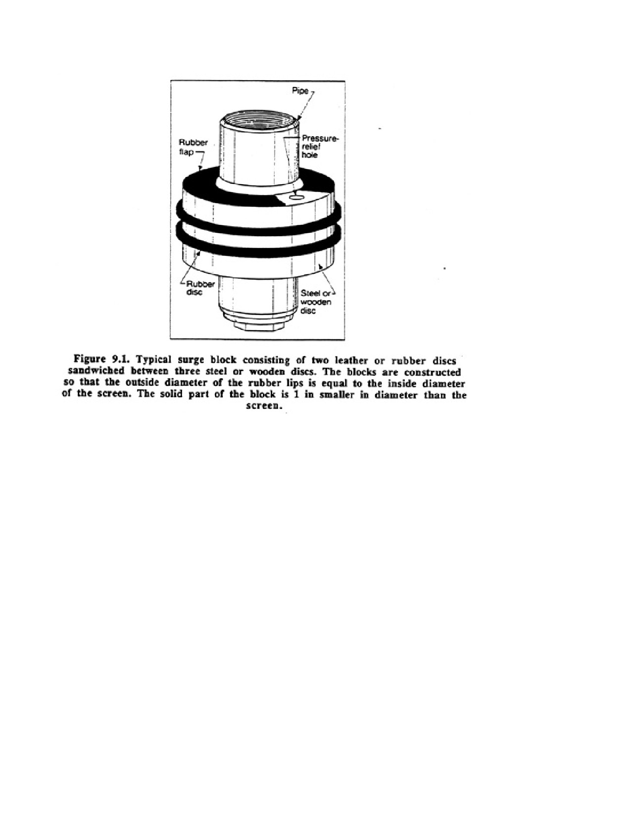
Page 135 of 360
9.3.3. Mechanical Surging
Another method of development is to force water to flow into and out of a screen by
operating a plunger up and down in the casing, similar to a piston in a cylinder. The tool
normally used is called a surge block, surge plunger, or swab (Figure 9.1). A heavy bailer
may be used to produce the surging action, but it is not as effective as the close-fitting surge
block. Although some drillers depend on surge blocks for developing screened wells, others
feel that this device is not effective and that it may, in some cases, even be detrimental
because it forces fine material back into the formation before the fines can be removed from
the well. To minimize this problem, fine material should be removed from the borehole as
often as possible.
Before starting to surge, the well should be bailed to make sure that water will flow into it.
Lower the surge block into the well until it is 10 to 15 ft beneath the static water level, but
above the screen or packer. The water column will effectively transmit the action of the block
to the screen section. The initial surging motion should be relatively gentle, allowing any
material blocking the screen to break up, go into suspension, and then move into the well. The
surge block (or bailer) should be operated with particular care if the formation above the
screen consists mainly of fine sand, silt, or soft clay which may slump into the screen. As
water begins to move easily both into and out of the screen, the surging tool is usually
lowered in steps to just above the screen. As the block is lowered, the force of the surging
movement is increased. In a well equipped with a long screen, it may prove more effective to
operate the surge block in the screen to concentrate its action at various levels. Development
should begin above the screen and move progressively downward to prevent the tool from
becoming sand locked.
Page 136 of 360
The force exerted on the formation depends on the length of the stroke and the vertical
velocity of the surge block. The vertical velocity depends on the weight exerted on the block
and the retraction speed. During retraction of the block continue the spudding motion to
avoid sand locking the block in the casing The speed of retraction and length of pull are
governed by the physical characteristics of the rig.
Continue surging for several minutes, then pull the block from the well. Air may be used to
blow the sediment out of the well if development is done with a rotary rig or if an air
compressor is available. Sediment can be removed by a bailer or sand pump when a cable
tool rig is used. The surging action is concentrated at the top of the screen, and this effect is
accentuated if the lower part of the screen is continually blocked off by the sand brought in
by the development process. In general, development can be accelerated if the amount of
sediment in the screen is kept to a minimum. A sump or length of casing installed beneath the
screen is helpful in keeping the screen free of sediment. Continue surging and cleaning until
little or no sand can be pulled into the welt Total development time may range from about 2
hours for small wells to many days for large wells with long screens.
Occasionally, surging may cause upward movement of water outside the well casing if the
washing action disrupts the seal around the casing formed by the overlying sediments. When
this occurs, use of the surge block must be discontinued or sediment from the overlying
materials may invade the screened zone.
Surge blocks sometimes produce unsatisfactory results in certain formations, especially when
the aquifer contains many clay streaks, because the action of the block can cause clay to plug
the formation. When this happens a reduction in yield occurs, rather than an increase. Surge
blocks are also less useful when the particles making up the formation are angular, because
angular particles do not Sort themselves as readily as rounded grains. In addition, if large
amounts of mica are present in the aquifer, the flat or tabular mica flakes can clog the outer
surface of the screen and the zone around the screen by aligning themselves perpendicular to
the direction of flow.
9.3.4. Air Developing by Surging and Pumping
Many drillers use compressed air to develop wells in consolidated and unconsolidated
formations. The practice of alternately surging and pumping with air has grown with the
great increase in the number of rotary drilling rigs equipped with large air compressors. In air
surging, air is injected into the well to lift the water to the surface. As it reaches the top of the
casing, the air supply is shut off, allowing the aerated water column to fat Air-lift pumping is
used to pump the well periodically to remove sediment from the screen or borehole, and is
accomplished by installing an air line inside an eductor pipe in the well. Eductor systems are
generally required for large diameter wells, when limited volumes of air are available, or
when the static water level is low in relation to the well depth. Most rotary figs, however,
have sufficient air capacity to use the casing as the eductor for 6 to 12-in diameter wells.
For removing large volumes of water and cuttings, a surfactant is mixed into a small volume
of water and then added to the airstream. The surfactant breaks up the water masses so they
can be lifted to the surface at a rather low velocity (50 to 200 ft/min), thereby reducing
air-volume requirements. During air development, however, surfactants are used only when
Page 137 of 360
compressor capacity is insufficient to lift water to the surface. Therefore, the contractor must
maintain uphole velocities in the range of 1,000 to 2,500 ft/min to achieve a reasonable
discharge.
Generally, it is not possible to predict what uphole velocity is actually needed because of
submergence factors, total pumping lift requirements, and the non-predictable way water will
enter the borehole. It is virtually impossible to predict beforehand the uphole velocities
required for air development procedures. In practice, the contractor ignores uphole velocity
considerations and concentrates on the air volume needed to lift the water adequately.
9.3.5. Air Development Procedures
Air development procedures should begin by determining that groundwater can flow freely
into the screen. Application of too much air volume in the borehole when the formation is
dogged can result in a collapsed screen. To minimize the initial pumping rate, the air line and
eductor (if used) can be placed at a rather shallow submergence. At this setting, even the
introduction of large air volumes will produce only a moderate pumping rate and, therefore,
will place only low collapse pressures on the well screen. Introduction of small air volumes
at greater submergence also will produce low yields.
Once uninhibited flow into the screen has been established, the eductor pipe (if used) is
lowered to within 5 ft of the bottom of the screen, assuming that sufficient pressure is
available to overcome the static head. Development can also start near the top of the screen,
depending on the preference of the driller. The air line is placed so that its lower end is up
inside the eductor pipe at the proper submergence level. Before blowing any water or drilling
fluid out of the well with a sudden large injection of air, the air lift should be operated to
pump fluids at a reduced rate from the well.
Air is released into the line and the well is pumped until the water is virtually sand free. The
valve at die air tank outlet is then closed, allowing the pressure in the tank to build. The
actual pressure required will depend on the starting submergence; 43 psi is needed for each
100 ft of starting submergence. In the meantime, the air line is lowered so that its lower end
is 1 ft or so below the eductor pipe. To initiate surging, the valve is opened quickly to allow
air from the tank to rush suddenly into the well. This tends to drive the water outward
Though the well screen openings. Ordinarily, a brief but forceful head of water will also
overflow or shoot from the casing and eductor pipe at the ground surface. When the air line is
pulled up into the eductor pipe after the first charge of air has been released into the welt the
air lift will again pump, thus reversing the flow (water flows into dhe well) and completing
the surging cycle.
The well is pumped until the water clears up, and then another "head" of air is released with
the air line set below the eductor pipe. To resume pumping, the air line is again lifted.
Surging cycles are repeated until the water is relatively free of sand or other fine particles
immediately after the screen has received an air blast. This indicates that development is
approaching completion in the region near the bottom of the eductor pipe. The airlift
assembly is then raised to a position about 5 ft higher and the same operations are repeated.
In this way, the entire screen is developed in 5-ft intervals. From time to time, the air lift
should be lowered to its original position near the bottom of the well and operated as a pump
to clean out any sand that has accumulated inside the screen.
Page 138 of 360
Under some conditions, the aquifer may become air locked when a large burst of air is
injected into the screened area of the well. Certain kinds of formations are more prone to air
locking, especially those formations that consist of stratified, coarse sand or gravel lenses
separated by thin, impermeable clay layers. Aquifers with good vertical hydraulic
conductivity are generally not affected. Surging with air usually does not lead to air locking.
If some air becomes trapped in the aquifer, however, it may impede the flow of water toward
the screen. In formations susceptible to air locking, surging with air should be avoided. Other
procedures such as high-velocity jetting with water or air may be more suitable in formations
where air trapping is a problem
9.3.6. High-Velocity Water Jetting Combined with Simultaneous Pumping
Although water jetting procedures are extremely effective in dislodging material from the
formation, maximum development efficiency is achieved when waterjetting procedures are
combined with simultaneous air-lift pumping or other pumping methods. This combination
of development techniques is particularly successful for wells in unconsolidated sands and
gravels. In water jetting, water is added to the well at a rate governed by the nozzle size and
the pop pressure. The volume of water pumped from the well should always exceed the
volume pumped in during jetting, because sediment removal is greatly enhanced with higher
discharge. Thus, the water level in the well will be kept below static level and some water
will move continuously from the formation into the well screen as the work proceeds. The
steady movement of water into the well helps remove some of the suspended material
loosened by the jetting operation. Ike air lift then pumps the sediment from the well before it
can settee in the screen.
The jetting water is usually clean water hauled to the drill site. In instances where sufficient
water supplies are unavailable, the contractor may use the water pumped from the well. To
avoid damaging the high-pressure pump, jetting nozzles, and screen, however, the fine sand
pumped from the well should be settled out in a tank or settling pit before this water is
recirculated. To enhance the development process, chemicals such as polyphosphates are
often added to the jetting water to help break up clays.
9.4. DEVELOPMENT OF ROCK WELLS
All drilling methods cause some plugging of fractures and crevices in hard-rock formations.
In softer formations such as sandstone, the borehole wall may become clogged with finer
material. In cable tool drilling, the bit action chips and crushes the rock and mixes it with
water and other fine material to form a slurry. The pounding of the bit forces some of this
slurry into the openings in the rock outside the borehole. When Wiling fluids are used in rock
drilling, they also may plug crevices. Even airdrilling methods can blow large quantities of
fine material into openings in the rock, causing drastic reductions in yield.
Any material that clogs openings in the rock aquifer must be removed by a development
procedure. The full yield of the formation can be realized only if all the features and crevices
can provide water to the well. Pumping alone sometimes pulls out the remaining sediment
because the openings in rock formations are relatively large in comparison with the pores in a
sand formation. However, many drillers have found that surging or other means of
development for rock wells is needed to obtain maximum capacity.
Page 139 of 360
9.5. AQUIFER_DEVELOPMENT TECHNIQUES
In many parts of the world, the only available groundwater comes from bedeck. If the rock is
massive, with few joints or faults, the volume of water available is often inadequate. In this
type of aquifer, yields can be increased dramatically by applying one or more aquifer
development techniques. Aquifer development, also called aquifer stimulation, can be
thought of as a second levy of development which can increase well yields far beyond those
obtained through typical well development. Aquifer development procedures in massive rock
are usually cost effective. Some of these methods are described below. Under most
circumstances, well development techniques are used before any aquifer development
methods are initiated.
9.5.1. Use of Acid
Acid can be used for both well and aquifer development in limestone or dolomite aquifers
and in some semiconsolidated aquifers that are cemented by calcium carbonate. Acid
dissolves carbonate minerals and opens up the fractures and crevices in the formation around
the open borehole, which is the intake portion of this type of well. Some of the acid,
however, is forced into cracks and fissures much farther from the well bore. The acid
dissolves some material naturally existing in the voids, thereby increasing the overall
hydraulic conductivity of the aquifer.
9.5.2. Hydrofracturing
Hydrofracturing has been used successfully since 1947 in oil wells to overcome well bore
damage, create reservoir fractures that improve well productivity, aid in secondary recovery
techniques, and facilitate injection of brine and industrial wastes. More recently, this method
has been used to increase the yields of low-production water wells in rock where joint
systems or fracture systems are poorly developed or so tight that little water can move
through them.
In hydrofracturing, high-pressure pumps are used to overcome the pressure of overlying rock
and to inject fluids into newly opened fractures. For every foot of depth, the overburden
pressure is usually equal to 1 psi. Therefore, at 200 ft the overburden pressure can be
overcome with a pump capable of pumping fluids at pressures greater than 200 psi. Oil field
hydrofracturing pumps can move fluids at pressures of 20,000 psi and more.
Cleaning the borehole walls before hydrofracturing is desirable because it removes driI1
cuttings, natural clays, or other mineral substances. This is done by mechanically brushing
the walls with an oversized wire brush assembly or by jetting the walls with high-velocity
water jets. Use of chemical additives such as diluted hydrochloric acid to remove calcium
carbonate deposits, or sodium tripolyphosphate to remove clays, can greatly facilitate this
prowess.
The following equipment is needed to apply the hydrofracturing technique: high pressure
water pump; power-takeoff hydraulic pump, quick-coupled to a hydraulic motor, valve
assembly dying flow to a packer inflation line and a water-injection line; one or more
Page 140 of 360
inflatable packers; and compressed air source to inflate the packers and increase downhole
pressure.
Hydrofracturing is accomplished by lowering an inflatable packer into a well and inflating it
at a depth somewhat above the production zone. Thus, the production zone is isolated from
the rest of the welt A fluid, usually water, is then pumped down through the packer into the
well at pressures of 500 to 10,000 psi About 800 to 1,000 psi is sufficient to fracture most
formations that are already somewhat fractured; much higher pressures may be needed if the
rock is massive with few cracks.
Hydrofracturing can increase water yield, improve reliability of water yield, reduce
suspended sediment in the water, increase water storage in the well, and reduce pumping
costs.
9.6. CONCLUSIONS
Patience, intelligent observation, and the right tools are required to develop a well correctly.
Well development is not expensive, considering the often remarkable results that can be
obtained in improving yields and eliminating sand pumping. Similarly, aquifer development
is often overlooked as an effective way to increase yields substantially.
CHAPTER 10.
FIELD TESTING OF
HYDRAULIC PARAMETERS
Pumping tests may be conducted to determine (l) the performance characteristics of a well
and (2) the hydraulic parameters of the aquifer. For a well-performance test, yield and
drawdown are recorded so that the specific capacity can be calculated. These data, taken
under controlled conditions, give a measure of the productive capacity of the completed well
and also provide information needed for the selection of pumping equipment. An accurate
test of a well before the pump is purchased pays for itself by assuring selection of a pump
that will minimize power and maintenance costs.
The second purpose of pumping tests is to provide data from which the principal factors of
aquifer performance—transmissivity and storage coefficient—can be calculated. This type of
test is called an aquifer test because it is primarily the aquifer characteristics that are being
determined, even though the specific capacity of the well can also be calculated. Aquifer tests
will predict (l) the effect of new withdrawals on existing wells, (2) the drawdowns in a well
at future times and different discharges, and (3) the radius of the cone of influence for
individual or multiple wells. Aquifer test data are more valuable today because a better
understanding of groundwater hydraulics now exists and new sophisticated methods of data
retrieval and analysis have been developed.
An aquifer test consists of pumping a well at a certain rate and recording the drawdown in
the pumping well and in nearby observation wells at specific times. There are two primary
types of aquifer tests: constant-rate tests and step-drawdown tests. In the constant-rate test,
Page 141 of 360
the well is pumped for a significant length of time at one rate, whereas in a step-drawdown
test the well is pumped at successively greater discharges for relatively short periods. Data
from both types of aquifer pumping tests can be analyzed to determine important hydraulic
characteristics of an aquifer and the well. The results from properly conducted tests are the
most important tool in groundwater investigations.
Measurements required for both well tests and aquifer tests include the static water levels just
before the test is started, time since the pump started, pumping rate, pumping levels or
dynamic water levels at various intervals during the pumping period, time of any change in
discharge rate, and time the pump stopped. Measurements of water levels after the pump is
stopped (recovery) are extremely valuable in verifying the aquifer coefficients calculated
during the pumping phase of the test.
Although aquifer testing is more involved than well testing, the methods presented below for
determining yields and measuring drawdown are used in both well and aquifer pumping tests.
These methods and procedures apply primarily to constant-rate and step-drawdown aquifer
tests.
10.1. CONDUCTING A PUMPING TEST
Pumping tests will not produce accurate data unless the tests are carried out methodically,
carefully recording the time, discharge, and depth measurements. Certain preliminary steps
should be taken to assure the reliability of pumping test data recorded during the actual test.
For instance, several days before the test is to be conducted, the test well should be pumped
for several hours to determine the following:
1. The maximum anticipated drawdown. (For most pumping tests, a major portion of the
drawdown will occur in the first few hours of pumping.)
2. The volume of water produced at certain engine (pump) speeds and drawdown.
3. The best method to measure the yield.
4. Whether the discharge from the pump is piped far enough away to avoid recharge.
5. Whether the observation wells are located so that they exhibit sufficient drawdown to
produce usable data.
Prior planning and experimentation with the equipment and personnel during preliminary
testing can eliminate potential errors that may occur during the actual pumping test. Never
begin the actual pumping test, however, until the water level in the aquifer has returned to the
decimal (pretest) static level following preliminary testing. About 24 to 72 hours should be
allowed, depending on the type of aquifer. Beginning a pumping test when the static water
level is below normal may eliminate early data that show discharge or recharge boundaries.
Without the early drawdown data, it may be impossible to obtain the correct transmissivity
and storage parameters for the aquifer.
The accuracy of drawdown data taken during a pumping test depends on the following:
Page 142 of 360
1. Maintaining a constant yield during the test.
2. Measuring the drawdown carefully in the pumping well and in one or two properly placed
observation wells.
3. Taking drawdown readings at appropriate time intervals.
4. Determining how changes in barometric pressures, stream levels, and tidal oscillations
affect drawdown data.
5. Comparing recovery data with drawdown data taken during the pumping portion of the
test.
6. Continuing the test for 24 hours for a confined aquifer and 72 hours for an unconfined
aquifer during constant-rate tests. For step-drawdown tests, 24 hours is usually sufficient for
either type of aquifer.
10.1.1. Maintaining a Constant Discharge
Variations in engine (pump) speed are a major cause of erratic drawdown data. If a gasoline
or diesel engine is used to drive the pump, the selected yield should be well below the
maximum capacity of the engine. Engines running at full throttle tend to vary significantly in
rpm, causing variations in the volume of water being pumped. Thus, it is good practice to
restrict the engine speed to one-half to two-thirds of the maximum Ape In this range, the
engine will run steadily, producing a more constant yield. Problems with varying rpm and
yield can be virtually eliminated if an electric motor is used to drive the pump.
It is vital that a complete set of drawdown data be obtained once the pumping test
commences. Therefore, for an aquifer test, the pump and power unit should be capable of
operating at a constant pumping rate for at least 48 hours. In cases where the observation
wells must be located at considerable distances from the pumped well, the pump must be
capable of operating for at least several days. Pump failure during the test is expensive and
even if the test is quickly resumed after repairs or refueling, the data are of questionable
value. Therefore, the pump should be in good repair and the fuel supply should be adequate
for the full term of the pumping test.
The pumping rate should be measured accurately and recorded periodically. Control of the
pumping rate during testing requires an accurate device for measuring the discharge of the
pump and a convenient means for adjusting the rate to keep it as nearly constant as possible.
A valve in the discharge line of the pump provides the best control. The discharge pipe and
the valve should be sized so that the valve will be from one-half to three-fourths open when
pumping at the desired rate. Unnoticed changes in speed that result from varying line voltage
on electric motors, or from variations in air temperature, humidity, or gasoline mixture on
gasoline engines, cause less fluctuation of the discharge when the pump is working against
the back pressure or head developed in Be partially closed valve. Changing the pumping rate
by controlling the pump speed is generally unsatisfactory.
Page 143 of 360
10.1.2. Direct Measurement Methods—Containers and Meters
A simple and accurate method for determining the pumping rate is to observe the time
required to fill a container of known volume. For example, if it takes 30 seconds to fill a
55-gal barrel, the pump is delivering 110 gpm. This method is practical however, for
measuring only relatively low pumping rates.
A commercial meter is more reliable when measuring large discharges. The dials on the
meter show the total volume discharged through the meter up to the time of observation.
Subtracting two readings taken exactly one minute apart gives the pumping rate. This is
perhaps the easiest apparatus to use.
10.1.3. Orifice Weir
The circular orifice weir is the device used most often to measure the discharge rate from a
high capacity pump. It will not measure the pulsating flow from a piston pump.
The orifice is a round hole with clean, square edges in the center of a circular steel plate. The
plate must be 1/16 in thick around the circumference of the hole and is fastened against the
outer end of a level discharge pipe so that the orifice is centered on the pipe. The end of the
pipe must be cut squarely so the plate will be vertical. The bore of the pipe should be smooth
and free of any obstruction that might cause abnormal turbulence. The discharge pipe must
be straight and level for a distance of at least 6 It before the water reaches the orifice plate.
This approach channel should be longer if possible. The pipe wall is tapped midway
between top and bottom with a 1/8-in or 1/4-in hole exactly 24 in from the orifice plate. Any
burrs inside the pipe resulting from the drilling or tapping of the hole should be filed off.
A device called a piezometer (manometer) tube is fitted to tills small hole to measure the
water head (pressure) in the discharge pipe. The piezometer consists of a clear plastic tube 4
or 5 ft long One end is connected to pipe fittings that are tapped into the hole in the discharge
pipe. The nipple, which is screwed into the tapped hole, must not protrude inside the pipe. A
scale is fastened to a support so that the vertical distance from the center of the discharge
pipe up to the water level in the piezometer tube can be measured. The water level in the
piezometer tube indicates the pressure head in the approach pipe when water is being
pumped through the orifice.
Besides making the parts accurately and setting up the device correctly in the field, two
precautions must be taken to assure good results. The diameter of the orifice should be less
than 80 percent of the inside diameter of the pipe that serves as the approach channel
The piezometer tube must be completely free of air bubbles, obstructions, or constrictions
when reading the pressure head. Air bubbles can be eliminated by lowering the tube between
readings so that water flows from it.
The gate valve used to control the pump discharge should be installed at least 10 pipe
diameters m the piezometer connection.
10.1.4. Weirs and Flumes
Page 144 of 360
Another method used to measure flow from a well is by means of a constriction placed in a
discharge channel originating at the well head. In most cases, the drilling contractor can
channelize the flow from a pumping well. A calibrated constriction placed in the channel
changes the level of the water in or near the constriction. By knowing the dimensions of the
constriction, the rate of flow through or over the constriction will be a function of the water
level. A simple depth determination near the constriction provides a discharge measurement.
10.1.5. Drill-Stem Testing
Drill-stem testing is routinely done in the oil industry to check on the potential yield from a
certain formation just after it has been drilled. This type of test is also done by some
contractors in the water well industry who have equipped themselves with the necessary
tools. A properly run drill-stem test will provide water quality information from the horizon
of interest, an estimate of the yield, and an indication of downhole pressures during pumping
and periods of no pumping.
In a drill-stem tests a special tool is attached to the drill string. Packers are installed at one or
both ends of the tool so that the intake portion of the tool is isolated from the drilling fluid
column in the borehole. The tool is also equipped with pressure sensors. After the tool is
lowered to the selected formation, multiple cycles of pumping and non-pumping provide
information on pressure, yield, and water quality. Highly sophisticated methods of data
analysis are used in the oil industry to evaluate results from drill-stem tests, but these
methods are not applicable to drill-stem tests for water wells. Data can simply be used "as is”
because boreholes are considerably shallower.
10.2. MEASURING DRAWDOWN IN WELLS
10.2.1. Observation Wells
Drawdown data can be taken from both the pumping well and appropriately placed
observation wells, but the accuracy of data taken from the pumping well is usually less
reliable because of turbulence created by the pump. Thus, at least one observation well
should be used when practicable. Furthermore, drawdown data from an observation well are
required to calculate the storage coefficient accurately, whereas transmissivity values may be
calculated on the basis of drawdown data taken from either a pumping well or observation
well.
Observation wells should be just large enough to allow accurate and rapid measurement of
the water levels. Small diameter wells are best, because the volume of water contained in a
large diameter observation well may cause a time lag in drawdown changes.
When observation wells are too close to the pumped well, the drawdown readings may be
affected by the stratification of the aquifer. Stratification distorts the distribution of hydraulic
head and drawdown in the vicinity of the pumped well during the aquifer test At any moment
after test pumping is started, the drawdown in a series of observation wells placed at a given
distance from the pumped well may vary if the screens are set at different depths within the
aquifer. These variations in drawdown become less as time of pumping increases. The
Page 145 of 360
distorted pattern of drawdown caused by stratification is eliminated at distances equal to
three to five times the aquifer thickness.
For unconfined aquifers, observation wells should be placed no farther than 100 to 300 It
from the pumped well. For thick confined aquifers that are considerably stratified,
observation wells should be placed within 300 to 700 ft of the pumped well. Locating the
wells too far away is not good practice because the pumping test must be continued for a
longer time to produce sufficient drawdowns at the most distant points, and small
measurement errors may be a significant percentage of the total drawdown in the observation
well.
Screens for observation wells should be installed at about the same depth as the central
passion of the screen in the production well. If this procedure is followed, the reduction in
pressure or water level at the observation well will usually occur within moments of its
occurrence in the pumping well (assuming the observation well is spaced at the collect
distance from the pumped well). Occasionally, observation wells are terminated in strata
above or below the one tapped by the pumped well to see if there is any hydraulic
interconnection between the formations. Naturally the response of these observation wells to
pumping may be delayed significantly, depending on the degree of hydraulic connection
The appropriate number of observation wells depends upon the amount of information
desired The data obtained by measuring the drawdown at a single location outside the
pumped well permit calculation of the average hydraulic conductivity, transmissivity, and
storage coefficient of The aquifer. If two or more observation wells are placed at different
distances, the test data can be analyzed by studying both the time-drawdown and the
distance-drawdown relationships. Using both these analytical methods provides greater
assurance that the calculated transmissivity and storage coefficient values are correct.
Before starting the pumping test, a complete program for depth-to-water measurements must
be laid out in advance. It is not necessary to make the measurements in all the wells
simultaneously. The watches used for timing the measurements, however, should be
synchronized so that the time of each reading can be referenced to the exact minute and hour
that pumping is started.
Using measurement devices that will give quick and accurate results, drawdown should be
measured in the pumping well and all observation wells.
The gauges ordinarily used to measure the depth of water in a well are:
1. Pressure gauge—reading in pounds per square inch (psi).
2. Altitude gauge—reading in feet and fractions of a foot.
3. Vacuum gauge—reading in inches of vacuum, or difference in pressure between mercury
under atmospheric pressure and water being pumped.
Well driller should become familiar with these gauges and their applications. They are
comparatively simple and easy to use, but for important tests they should be calibrated wide
master gauges. Readings will be more accurate if the range of the gauge only slightly exceeds
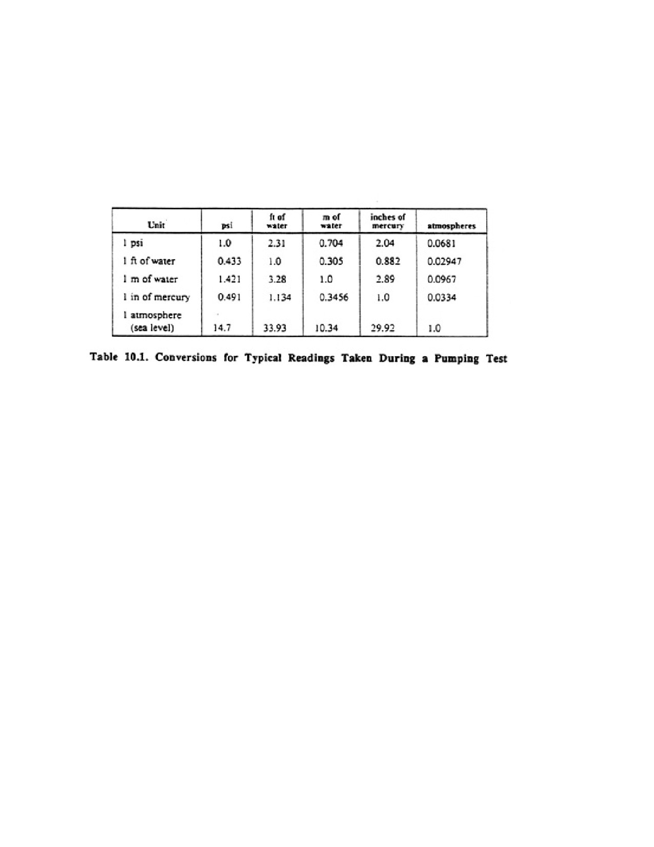
Page 146 of 360
die range of the anticipated drawdown values. Pressure gauges are most often used by
drilling contractors.
In English engineering units, the depth of a water column is measured in feet or pounds per
square inch (psi). For example, when using a pressure gauge, the readings are in psi and must
be multiplied by 2.31 to convert to feet of water. To convert a reading in feet to one in psi the
reading is multiplied by 0.433. Table 10.1 contains conversions for the typical types of
readings taken during a test.
The most common method of measuring water levels in a puking well is the air-line method,
which woks on the principle of measuring the air pressure needed to force the water out of a
tube that extends down the well to some known depth below the water level. The air pressure
is then converted to an equivalent column of water above the bottom of the air line. This
method is not nearly as accurate as the steel tape or electric probe, but it is usually sufficient
and the most practical method for use in a pumping well.
Figure 10.1 shows the installation of an air line in a well for the purpose of determining the
depth to water. The device works on the principle that the air pressure required to push all the
water out of the submerged portion of the tube equals the water pressure of a water column
of that height. If this pressure is expressed in feet of water, the depth to water can be
calculated. The air line consists of a small-diameter plastic (PVC) pipe or tube of sufficient
length to extend from the top of the well to a point several feet below the lowest anticipated
water level to be reached during the test. The exact length of the air line must be measured as
it is placed in the well. If flexible tubing is used, steps must be taken to assure that the tubing
hangs vertically and does not spiral inside the well casing. The air line and connections at the
ground surface must be completely air tight. Before starting the pumping test, the line is
prepressurized and the gauge pressure recorded. During pumping, the pressure in the line is
reduced; this pressure drop can be directly related to feet of waterlevel fall.
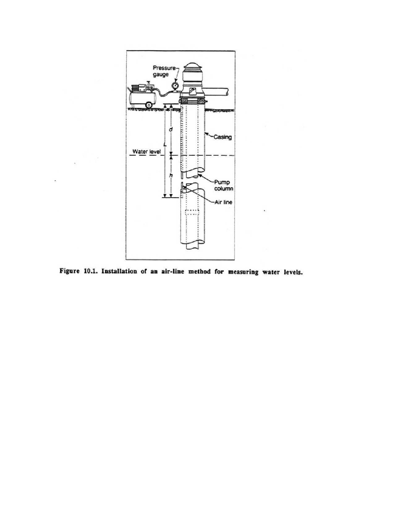
Page 147 of 360
For example, suppose the distance from the top of the well casing to the lower end of the air
line is 95 ft. As air is pumped into the line, assume that a maximum reading of 46 ft is
reached on the gauge. The depth to water is then the difference between 95 and 46, or 49 ft.
This is the static water level. After the pump is started, the water level in the well drops, the
submerged length of the air line decreases, and the pressure indication on the gauge drops
accordingly. A gauge reading of 34 ft. for instance, would mean that the submerged length of
the air line has decreased by 12 ft (46-34) and the depth to water has changed to 95 minus 34,
or 61 ft. This indicates a drawdown of 12 ft below the static water level. If the gauge reads in
psi, each leading must be multiplied by 2.31 to convert it to feet of water. For example, a
reading of 15 psi corresponds to a pressure head of 34.6 ft of water.
The air-line method is generally not accurate enough for use in observation wells during an
aquifer test, but it is the most practical means for measuring water levels in a pumped weld
Because measuring depths during pumping tests is labor intensive, automatic depth indicators
have been developed.
The most widely used automatic water level measuring device is the mechanical,
float-actuated, drum recorder. This device can be geared to provide a continuous water level
record for periods of time ranging from 4 hours to one month, and can record water levels
with an accuracy of 0.001 ft. A less common device relies on an electronically actuated
pressure transducer placed in the well at some depth below the water level. Transducers
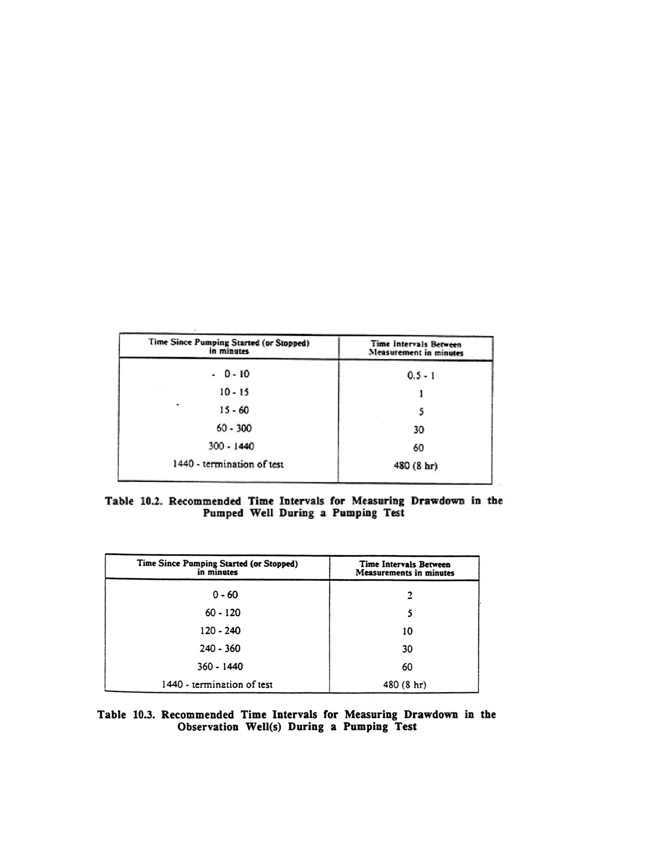
Page 148 of 360
measure feet of water (hydraulic head) above the transcducer. The amount of head over the
transducer is automatically printed out for any selected time after pumping commences; the
time and feet of head can be printed on a strip chard With proper calibration this device will
also measure water levels accurate to 0.005 ft.
In automated drawdown measuring systems, transducers are placed in each well and
electrically connected to analyzer, computer, and printer-plotter equipment
10.2.2. Recommended Time Intervals for Measuring Drawdown During a
Constant-Rate Pumping Test
All watches of observers should be synchronized before the test begins; times should be
recorded to the nearest 10 seconds. Water-level measurements for the pumped well should be
recorded at the times suggested in Table 10.2. Of course, drawdown in wells more distant
from the pumping well will not occur immediately. Drawdown readings in the observation
wells should be taken at the intervals recommended in Table 10.3.
Page 149 of 360
Early test data are extremely important, and as much information as possible must be
obtained in the first 10 minutes of pumping for every observation well. The reason for this is
that, as the cone of depression moves outward from the well, it may encounter
inhomogeneities in the ground which cause either an acceleration or a deceleration of
drawdown with increasing time. Any unusual event (stoppage of pump, onset of weather
change, or passage of a train) should be noted, along with the time it occurred.
Ideally, pumping tests should be continued until equilibrium is reached, that is, until the cone
of depression stabilizes. In practice this is rarely possible. In confined aquifers, the cone of
depression spreads rapidly because no actual dewatering takes place; only a pressure
reduction is occurring outward from the well. Thus, 24 hours is usually sufficient to record
enough reliable data for confined aquifers. To gain enough information for unconfined
aquifers, 72 hours are usually required to dewater the materials within the cone of depression,
because of the slow downward percolation of water in many stratified deposits. This time can
be reduced if equilibrium conditions are established before 72 hours have elapsed. In no
event should pumping tests be terminated prematurely, however, because the limited data
collected may not reveal the true nature of the aquifer.
Barometric or tidal changes can influence drawdown data. For example, a barometric
pressure change of 1 in of mercury can result in a rise or fall of up to 1 ft in the
potentiometric surface for confined aquifers that have high barometric efficiency. Barometric
efficiency refers to the aquifers ability to transmit changes in atmospheric pressure. Record
the nature and time of any weather changes on the drawdown data sheet. Unusually high or
low oceanic tides can also affect drawdown data in wells near coastlines.
10.2.2.1. Recovery Data
Whenever possible, recovery data should be taken to verify the accuracy of pumping data.
Often, the recovery data will be more reliable because no pumping is required and any
previously inexperienced personnel will have learned paper measurement techniques by the
time recovery data can be taken. Recovery measurements should be recorded with the same
frequency as those taken during the pumping portion of the aquifer test.
CHAPTER 11.
PUMPS AND PUMPING
The primary function of a pump is to add hydraulic energy to certain volumes of fluid. This
is accomplished when the mechanical energy imparted to the pump Cam a power source is
transferred to the fluid, thereby becoming hydraulic energy. Thus, a pump serves to transfer
energy from a power source to a fluid, thereby creating flow or simply creating greater
pressures on the fluid. Pumps can serve many different purposes. These include raising a
liquid from one level to another, moving a fluid through a pipeline imparting a high velocity
to water, and moving liquids against a resistance.
A pump can impart three types of energy to any fluid: head, pressure, and velocity. The
amount of each type of hydraulic energy will vary from place to place in a system. For
example, when water is at rest in a storage tank, it possesses head energy but no velocity or
Page 150 of 360
pressure energy. Once water starts to flow from the storage tank, it has head, pressure, and
velocity energy. As water flows from the end of a pipe or hose, the head and pressure energy
are transformed to velocity energy alone.
Pumps are installed in water wells to lift the water to the ground surface and deliver it to the
point of use. Many types and sizes of pumps are available, ranging in power from a fraction
of one horsepower to several thousand horsepower. In the water well industry, pumps are
classified generally into two groups: shallow-well pumps and deep-well pumps. A
shallow-well pump is mounted at ground level and removes water from the well by suction
lift. A deep-well pump is installed within the well casing, with the pump inlet submerged
below the pumping lever The deep-well pump must be used for any well where the pumping
level is below the limit of suction lift (approximately 20 to 25 ft).
A general method of classifying pumps is to divide them into two groups: positive
displacement and variable displacement. Although positive displacement pumps are used
extensively in groundwater monitoring wells, in hand-pump-equipped wells, and in
wind-powered wells, they are used rarely for domestic or large-capacity water wells. Thus,
variable displacement pumps will be discussed first in this chapter because of their wide use
in the water well industry.
11.1. VARIABLE DISPLACEMENT PUMPS
The distinguishing characteristic of variable displacement pumps is the inverse relationship
that exists between the rate at which they deliver water and the head against which pumping
takes place. For example, as the head increases, the rate of pumping decreases.
The pumping rate in any variable displacement pump is dependent upon the pressure or
number of feet of lift against which the pump is operating. A general term for this pressure is
head or static lift, and can be calculated by adding the pumping water level in the well to the
lift required above the discharge point.
The lift required, however, is only a part of the total head that the pump would be operating
against. Friction losses that occur in the pipe during pumping must also be added to the
lifting head to determine dynamic head or total dynamic head. These friction losses are
sometimes referred to as the friction head. Friction head represents the combined head losses
in the pipe, valves, and other fittings caused by flow velocity, viscosity, and specific gravity
of the fluid. The major types of variable displacement pumps are:
1. Centrifugal pumps
a. Suction lift
b. Deep-well turbine
c. Submersible turbine
2. Jet pumps
3. Air-lift pumps
11.1.1. CENTRIFUGAL PUMPS
The basic principles of the centrifugal pump were recognized about 300 years ago. In the
latter part of the 19th century, the steam turbine and the electric motor were developed as
Page 151 of 360
suitable sources of power for pumps. The centrifugal pump then became popular as a
pumping device. It is capable of delivering large quantities of water, against high as well as
low head conditions, with good efficiency.
There are many design variations in centrifugal pumps. Originally designed as a pump to be
located at or near ground surface for suction-lift or booster service, it soon was adapted to
installation under water in wells, first by long shaft extensions in large caissons (vertical
turbine), and later in compact form as the familiar deepwell (submersible) turbine pump.
The basic principle of centrifugal pumping can be illustrated by considering the effect of
swinging a pail of water around in a circle at the end of a rope. Centrifugal force causes the
water to press against the bottom of the pail rather than run out at the open end If a hole were
cut in the bottom, water would discharge through the opening at a velocity related to the
centrifugal force. If an airtight cover were put on the pail a partial vacuum would be created
inside the pail as water is discharged. This vacuum could draw additional water into the pail
through an intake pipe connected to the cover if the lift were not too great
11.1.2. CENTRIFUGAL PUMP DESIGN
There are five distinct types of centrifugal pumps, each of which can be modified, within
limits, by changing the impeller design to provide different operational characteristics An
impeller is the rotary element in a centrifugal pump that imparts a high velocity to the water.
The five pump types are:
1. Turbine (diffusers
2. Volute
3. Mixed flow
4. Axial flow (propeller)
5. Regenerative
Water well contractors generally use only the turbine pump. In this type of pump, the
impeller is surrounded by diffuser vanes that provide gradually enlarging passages in which
the velocity of the water leaving the impeller is reduced, thereby increasing the pressure.
Because so many turbine pumps are used in deep-lift installations, the term "turbine pump" is
often misapplied to all centrifugal pumps used in these installations.
The volute pump differs from the turbine pump in that there are no diffuser vanes and the
impeller is housed in a spiral-shaped case. Similar to a turbine pump, the velocity of the
water is reduced upon leaving the impeller, thus transforming velocity head to pressure head.
Mixed-flow centrifugal pumps use both the centrifugal force generated by an impeller and
some lifting action produced by a propeller to move water. Mixed-flow pumps are used
extensively for large-capacity installations operating against relatively low heads.
Axial-flow pumps are often called propeller pumps because they produce most of the flow by
the lifting action of propellers. They are used almost exclusively for large-capacity pumping
against extremely low heads.
11.1.3. SEMI-OPEN IMPELLERS
Page 152 of 360
Semi-open impellers have a series of curved but partially unsupported vanes that are
enclosed at the top only. Commonly, this type of impeller is used for pumping liquids
carrying some solids. Lack of close clearance or restricted passageways is desirable to
prevent plugging.
11.1.4. CLOSED IMPELLERS
Closed impellers have vanes that are enclosed at the top and bottom. This provides a
controlled area to channel water through the impeller. Flow enters the eye of the impeller and
follows the enclosed vane into the next assembly. The tolerances between the outside skirt of
the impeller and the vertical edge of the bowl assembly are quite close and do not allow
much leakage past the impeller if placed properly in the bowl.
1 1.1.5. CAVITATION
Cavitation is a condition that occurs when the pressure acting on a stream of liquid falls to or
below the vapor pressure of that liquid. When water enters the eye of the impeller in a turbine
pump, the velocity increases, thereby causing a corresponding reduction in pressure. If the
pressure falls below the vapor pressure (at the liquid's temperature), the liquid will begin to
vaporize, and part of the flow through the pump will consist of vapor pockets. At some point,
the liquid will reach an area of higher pressure, causing the pockets to collapse at such a
rapid rate that a rumbling noise can be heard. The collapse of these pockets is so violent that
it causes pitting on the impeller and bowl surface.
In propeller pumps, water from the larger inlet area entering the throat ahead of the propeller
accelerates rapidly. If the head is increased too much, the capacity is reduced to the point
where insufficient fluid exists to fill the space between the propeller vanes. Vacuum pockets
develop along the vanes momentarily, but almost instantly the space is filled as the liquid
crashes against the propeller vanes. The force of the liquid hitting the vane surface can cause
severe pitting of the vane.
Cavitation is generally indicated by fluctuations or reductions in yield, erratic power
consumption (fluctuating amperage readings), and noisy operation.
11.1.6. SUCTION-LIFT PUMPS
Suction lift is developed by creating a negative pressure at the pump intake. Atmospheric
pressure on the free surface of water in a well forces water up into that part of the pump
where the reduced pressure has been developed. The maximum - suction lift is limited by
four factors: atmospheric pressure, vapor pressure, head losses attributable to friction, and
NPSH requirements of the pump itself.
Atmospheric pressure varies with atmospheric conditions and elevation. For practical
purposes, it is assumed that the Earth's atmosphere normally exerts a pressure of 14.7 psi at
sea level—the equivalent of about 34 ft of water heal Under normal conditions at sea level,
therefore, it might be assumed that a water colony would be lifted 34 ft if a perfect vacuum
could be produced by a pump.