NATIONAL DRILLING ASSOCIATION DRILLER’S MANUAL (2005) - page 1
Page 4 of 360
2.2. Transmissivity
2.3. Groundwater Flow Velocities
2.4. Collection of Hydrogeologic Data
2.4.1. Observation Wells
2.4.2. Piezometers
2.4.3. Potentiometric Surface
CHAPTER 3.WELL HYDRAULICS
3.1. Definition of Terms
3.1.1. Static Water Level
3.1.2. Pumping Water Level
3.1.3. Drawdown
3.1.4. Residual Drawdown
3.1.5. Well Yield
3.1.6. Specific Capacity
3.2. Nature of Converging Flow
3.2.1. Radius of Influence
3.2.2. Coefficient of Storage
3.2.3. Coefficient of Transmissivity
3.3. Cone of Depression
CHAPTER 4.WELL DRILLING METHODS
4.1. Cable Tool Method
4.2. Direct Rotary Drilling
4.3. Reverse Circulation Rotary Drilling
4.3.1. During Drilling
4.4. Air Drilling Systems
4.5. In-Verse Drilling
4.6. Dual-Wall Reverse Circulation Rotary Method
4.7. Drill-Through Casing Driver
4.8. Boring with Earth Augers
4.8.1. Bucket Auger
4.8.2. Solid-Stem Auger
4.8.3. Hollow-Stem Auger
4.9. Drilling Procedures when Boulders are Encountered
4.9.1. Cable Tool
4.9.2. Direct Rotary
4.9.3. Reverse Rotary
4.9.4. Air Rotary with Casing Driver
4.9.5. Several General Points can be Made Concerning Drilling Through Boulders
4.10 Fishing Tools
4.11. Grouting and Sealing Well Casing
4.11.1. Proportioning Cement Grout
4.11.2. Mixing the Grout
4.11.3. Slurry Placement Methods
4.11.4. Tremie Pipe Outside Casing
4.11.5. Tremie Pipe Inside Casing (Inner String Method)
Page 5 of 360
4.11.6. Casing Method of Grouting
4.11.7. Grouting Failures
4.11.8. Installation of Bentonite Grout
4.12. Plumbness and Alignment
4.13. Conclusions
CHAPTER 5. DRILLING FLUIDS
5.1. Types of Drilling Fluids
5.2. Functions of a Drilling Fluid
5.3. Properties of Water Based Drilling Fluids
5.3.1. Density
5.3.2. Flow Characteristics of Drilling Fluids
5.3.3. Viscosity
5.3.3.1. Viscosity of Drilling Fluids Made with Clay Additives
5.3.3.2. Viscosity of Drilling Fluids Made with Polymeric Additives
5.3.4. Gel Strength of Drilling Fluids Made with Clay additives
5.3.5. Gel Strength of Drilling Fluids Made with Polymeric Additives
5.3.6. Filtration
5.3.7. Design of Mud Pits
5.4 Air Drilling
5.4.1. Dry-Air Systems
5.4.2. Air-Mist Systems
5.4.3. Air-Foam Systems
5.4.4. Aerated Drilling Fluids
5.4.5. Regulating the Air-Foam Drilling System
5.5. Drilling Fluid Additives
5.6. Guidelines for Solving Specific Drilling Fluid Problems
5.7. Conclusions
CHAPTER 6.WELL SCREENS AND METHODS OF SEDIMENT-SIZE
ANALYSIS
6.1. Continuous-Slot Screen
6.1.1. Screen Diameter
6.2. Other Types of Well Screens
6.3. Well Points
6.4. Optimum Well Screen Open Area
6.5. Sediment Size Analysis
6.5.1. Sediment Size
6.5.2. Slope and Shape of Curve
CHAPTER 7.WATER WELL DESIGN
7.1. Well Screen Length
7.2. Design of Domestic Wells
7.3. Design for Sanitary Protection
7.4. Special Well Designs
Page 6 of 360
CHAPTER 8. INSTALLATION AND REMOVAL OFWELL SCREENS
8.1. Pull-Back Method
8.1.1. Packers
8.1.2. Setting the Screen in Wells Drilled by the Cable Tool Method
8.1.3. Setting the Screen in Wells Drilled by the Rotary Method
8.2. Open-Hole Methods for Screen Installation
8.2.1. Double-String Installation
8.2.2. Single-String Installation
8.3. Filter Packed Wells
8.3.1. Selection and Placement of Filter Pack 8.3.2. Filter Pack Procedures for Wells
8.3.2.1. Drilled by the Cable Tool Method
8.3.2.2. Filter Pack Procedure for Wells Drilled by the Rotary Method
8.3.3. General Guidelines for Installing Filter Packs
8.4. Installation of Plastic Screens
8.4.1. Telescope Installations
8.4.2. Setting Screens in Open Boreholes (Direct Attached) 8.5. Other Methods
8.5.1. Bail-Down Procedure
8.5.2. Wash-Down Method
8.6. Installing Well Points
8.7. Removing Well Screens
CHAPTER 9. DEVELOPMENT OFWELLS
9.1. Well Development
9.2. Factors that Affect Well Development
9.2.1. Well Completion Method
9.2.2. Open Area and Slot Configuration
9.2.3. Slot Size
9.2.4. Drilling Fluid Type
9.2.5. Filter Pack Thickness
9.2.6. Type of Formation
9.3. Well Development Methods
9.3.1. Overpumping
9.3.2. Backwashing
9.3.3. Mechanical Surging
9.3.4. Air Developing by Surging and Pumping
9.3.5. Air Development Procedures
9.3.6. High-Velocity Water Jetting Combined with Simultaneous Pumping
9.4. Development of Rock Wells
9.5. Aquifer Development Techniques
9.5.1. Use of Acid
9.5.2. Hydrofracturing
9.6. Conclusions
CHAPTER 10. FIELD TESTING OF HYDRAULIC PARAMETERS
10.1. Conducting a Pumping Test
10.1.1. Maintaining a Constant Discharge
Page 7 of 360
10.1.2. Direct Measurement Methods -- Containers and Meters
10.1.3. Orifice Weir
10.1.4. Weirs and Flumes
10.1.5. Drill-Stem Testing
10.2. Measuring Drawdown in Wells
10.2.1. Observation Wells
10.2.2. Recommended Time Intervals for Measuring Drawdown During a Constant-Rate Pumping Test
10.2.2.1. Recovery Data
CHAPTER 11. PUMPS AND PUMPING
11.1. Variable Displacement Pumps
11.1.1. Centrifugal Pumps
11.1.2. Centrifugal Pump Design
11.1.3. Semi-Open Impellers
11.1.4. Closed Impellers
11.1.5. Cavitation
11.1.6. Suction-Lift Pumps
11.1.7. Deep-Well Turbine Pumps
11.1.8. Vertical Turbine Pumps
11.1.9. Submersible Pump
11.1.10. Jet Pumps
11.1.11. Priming Centrifugal Pumps
11.2. Positive Displacement Pumps
11.2.1. Rotary Pumps
11.2.2. Piston Pumps
11.2.3. Priming Positive Displacement Pumps
11.3. Pumps Used to Circulate Drilling Fluid
11.4. Air-Lift Pumping
11.5. Pump Selection
11.6. Pitless Adaptors
CHAPTER 12. GROUNDWATER MONITORING TECHNIQUES
12.1. Major Federal Legislation Pertaining to Groundwater Quality and Monitoring Procedures
12.2. Groundwater Contamination Sources
12.3. Effect of Aquifer Characteristics on the Spread of Groundwater Contamination
12.4. Delineating Contaminant Plumes
12.5. Monitoring Contaminant Movement (Transport)
12.6. Locating Monitoring Wells
12.7. Personnel Safety at Monitoring Sites
12.8. Design of Monitoring Wells
12.8.1. Screen Criteria for Monitoring Wells
12.8.2. Filter Pack Design
12.8.3. Installation Procedures
12.9. Sampling Monitoring Wells
12.10. The Task of Groundwater Protection
12.11. Aquifer Restoration
12.12. Conclusions
Page 8 of 360
CHAPTER 13. SEALING ABANDONED WELLS AND BOREHOLES
13.1. Abandonment of Wells
13.2. General Timelines for Abandonment
13.3. General Abandonment Procedures
13.4. Sealant Settlement
13.5. Abandonment Documentation
13.6. Conclusions
CHAPTER 14. SUBSURFACE EXPLORATION TOOLS AND EQUIPMENT
14.1. General Planning
14.2. Exploration Program
14.2.1. Exploration Plan
14.2.2. Types of Borings
14.2.3. Exploration Spacing
14.2.4. Sampling Requirements
14.3. Right-of-Entry, Permits and Utilities
14.4. Borehole Location Tolerance
14.5. Drilling Equipment
14.6. Exploration Methods
14.7. Borehole Advancement
14.8. Borehole Stabilization
14.9. Special Exploration Techniques
14.10. “Wash” Sampling
14.11. Split-Barrel or Split-Spoon Open Drive Sampling
14.12. Thin-Wall Tube Sampling
14.13. Rotary core Barrel Sampling
14.14. Block Sampling
14.15. Rock Core Sampling
14.16. Rotary Core Barrel Types
14.17. Specialty Core Barrel Types
14.18. Integral Rock Core Sampling
14.19. Rock Structure Orientation Methods
14.19.1. Structural Orientation Methods which are Applied from Within the Completed Borehole
14.20. Exploration Difficulties
14.21. Specific Geologic Problem Conditions
14.22. Groundwater Conditions
14.23. Borehole Sealing
14.24. Sampling Preservation and Shipment
14.24.1. Jar Samples
14.24.2. Thin-Wall Tubes
14.24.2.1. Cohesive Samples
14.24.2.2. Granular Samples
14.24.3. Rock Core
14.24.4. Bulk Samples
14.24.5. Environmental Test Samples
14.24.6. Non-Containerized Samples
Page 9 of 360
14.25. Logging
14.26. Improper Drilling Techniques
CHAPTER 15. DRILLING, SAMPLING AND INSTALLATION PROCEDURES
15.1. General Field Procedures
15.2. Rock Coring
15.2.1. Purpose
15.3. Rock Quality Designation (RQD)
15.4. Piezometers
15.4.1. Purpose
15.4.2. Procedures
15.5. Exploratory Test Pits
15.6. Thin-Walled Open Drive Sampling
15.6.1. Purpose
15.6.2. Procedure
15.7. Mechanical Stationary Piston Sampling
15.7.1. Purpose
15.7.2. Procedure
15.8. Hydraulic Piston Sampling
15.8.1. Purpose
15.8.2. Procedure
15.9. Denison Sampling
15.9.1. Purpose
15.9.2. Procedure
15.10. Pitcher Sampling
15.10.1. Purpose
15.10.2. Procedure
15.11. In Situ Borehole Testing
15.11.1. General
15.11.2. Types of Tests
15.11.3. Correlation Tests
15.11.3.1. Standard Penetration Test
15.11.3.2. Dynamic Penetration Tests
15.11.4. Strength and Deformation
15.11.4.1. Penetrometers
15.11.4.2. Pressuremeters
15.11.4.3. Stress or Shear Devices
15.11.4.4. In Situ Testing Procedures
15.11.4.5. Standard Penetration Test (SPT)
15.11.4.6. Dynamic Penetrometer Tests
15.11.4.6.1. Recoverable Type
15.11.4.6.2. Expendable Type
15.11.4.7. Static Cone Penetrometer Tests
15.11.4.7.1. Mechanical Cone
15.11.4.7.2. Electrical Cone
15.11.4.8. Pressuremeter Test
15.11.4.8.1. Procedure
15.11.4.8.2. Equipment
Page 10 of 360
15.11.4.8.3. Testing
15.11.4.9. Borehole Shear Test (Iowa Type)
15.11.4.9.1. Procedure
15.11.4.10. Water Pressure Test
15.11.4.10.1 Equipment
CHAPTER 16. DRILLING SAFETY GUIDE
1. An Introduction to Drilling Safety
2. Governmental Regulations
3. The Safety Supervisor
4. Individual Protective Equipment
5. Housekeeping On and Around the Drill Rig
6. Maintenance
7. Hand Tools
8. Clearing the Work Area
9. Start-Up
10. Drilling Operations
11. Overhead and Buried Utilities
12. Supplying Power to the Job Site
13. Contact with Electricity
14. Wire Line Hoists, Wire Rope and Hoisting Hardware
15. Cathead and Rope Hoists
16. Auger Drilling
17. Rotary and Core Drilling
18. Air Drilling
19. Transporting a Drill Rig
20. Loading and Unloading
21. Off-Road Movement
22. Tires, Batteries and Fuel
23. First Aid
24. Drill Rig Utilization
25. Drill Rig Alterations
26. Shut-Down
27. Welding and Cutting Torch Safety
28. Fire on the Rig
29. Drilling Equipment Safety Labels
GLOSSARY:
APPENDIX A Part 1; APPENDIX A Part 2; APPENDIX A Part 3
APPENDIX B Part 1; APPENDIX B Part 2; APPENDIX B Part 3
CHAPTER 1.
BASIC GEOLOGY AND HYDROLOGY
For years nearly everyone took water for granted. Few persons worried that water resources had finite
limits, that they could be lost to contamination or outright removal, or that the pressures of a burgeoning
population would create physical and chemical stresses on these resources never dreamed of only a
Page 11 of 360
generation ago. Since the 1960s, however, a keen awareness of the fragility of these resources has
developed throughout the world. Once a resource is endangered by the impact of man, society can be
required to expend large sums of money and time to determine what the problems are and to develop
potential solutions.
Water is one of the fundamental resources. It is at once one of the most common substances and one of
the most unusual. Although its chemical formula is deceptively simple, the effect of water on almost
everything in our environment is far more important than might be imagined.
1.1. Properties of Water
Water is often called "the universal solvent". It has the extraordinary ability to dissolve a broad range of
substances. In fact, it dissolves more substances in greater quantities than any other liquid. The salinity
of the world's oceans is a direct result of water's ability to dissolve rock materials as water flows
overland to the sea. Eventually, an element such as calcium becomes so abundant in sea water that it
precipitates out, forming crystals of the mineral calcite. So much calcite is precipitated that thick layers
of a sedimentary rock, called limestone, form on the ocean floor. This rock may later be uplifted by
large-scale geologic forces to form part of the land areas of the world. If conditions are just right, the
limestone may in time provide huge reservoirs for underground water resources.
Water has the highest heat of vaporization of any liquid. In other words, huge amounts of heat energy are
required to evaporate even small quantities of water. The subsequent release of this energy through
condensation during rainstorms provides an important energy source for driving weather systems.
Because of water's high heat capacity, the presence of oceans, lakes, and large rivers prevents extreme
fluctuations in local temperatures. Coastal communities have much more uniform temperature regimes
than do areas farther inland. Within the human body, water is critical in maintaining uniform body
temperatures. Without the large volume of water in our bodies (approximately 75 percent), we would
warm up or cool down much more rapidly than we do.
Water has other unusual physical and chemical characteristics that play a large but often unrecognized
role in our daily lives. For example, part of any volume of water has a natural tendency to break down
spontaneously into hydrogen (H+) and hydroxyl (OH-) ions. This process is called dissociation. When an
abundance of these charged ions are available, an electric current can be transmitted through the liquid.
The dissociation process is enhanced when an acid is added lo water. For instance, automobile batteries
contain an electrolyte (acid added to water) which contains abundant H+ and OH- ions. The electrolyte
permits batteries to store and give up electricity rapidly.
1.2. Water and Our Environment
The Earth's atmosphere contains from 0.02 to 4 percent water by volume, depending on location. In
addition to providing sources for precipitation, atmospheric water vapor affords two powerful safeguards
for life on Earth. First, it intercepts some ultraviolet (short-wave) radiation from the sun. It is this type of
solar radiation that produces skin cancer in humans. Second, much of the heat that the Earth receives
from the sun is radiated back into space. Atmospheric water vapor, however, intercepts some of this
potential heat loss and redirects part of it back to Earth, while part is retained in the atmosphere. These
phenomena produce a warm atmospheric envelope around the Earth that prevents large daily temperature
fluctuations similar to those found on the moon.
Page 12 of 360
Another unusual feature of water related to its molecular structure is the great capacity of water
molecules to cling to one another. This characteristic, called hydrogen bonding, gives water the highest
surface tension of any liquid. Therefore, it is relatively difficult to pass anything through a water surface.
This physical property gives water vapor its tendency to form droplets when condensing in the
atmosphere.
Unlike most other liquids, water reaches its maximum density at 39.2°F, which is well above its freezing
point of 32°F. As a result, lakes in colder climates do not freeze from the bottom up, but instead are
covered each winter with a relatively thin layer of ice. Biological activity would virtually cease in lakes
if they were filled with ice each winter. In the colder climates of the world, air temperatures pass back
and forth through the freezing point many times each year. Water in shallow cracks and crevices of rocks
found in these climates freezes and thaws as many as 70 times annually. The force exerted by the
freezing water, as much as 30,000 psi is sufficient to crack even the most durable rock. This process,
called frost wedging, can cause extensive destruction of large rock masses. Eventually, these rock
materials are reworked by the agents of erosion-running water, glacier ice, and wind-into various kinds
of unconsolidated sediment. Some of these sediments serve as storage sites for groundwater.
Water plays a major role in virtually every aspect of human life. Regrettably, too few persons understand
the physical and chemical properties of water well enough to effectively solve urgent and nearly
universal problems relating to its cost, availability, distribution, and contamination. Water problems of
any type stem largely from lack of knowledge and, therefore, from mismanagement of the natural system
These problems are intensified by the technological impact of man on that system.
Water is such a fundamental part of the Earth that anyone studying water must first understand how the
Earth evolved and the changes that have taken place in and near the Earth's crust over the last several
billion years. In the past, geologists thought the Earth was more or less static; that is, its topographic
features and internal structure remain relatively constant. Recent discoveries now demonstrate that the
Earth is a dynamic planet. Subtle changes are occurring constantly in the arrangement of continents, the
building and destruction of mountain chains, the creation and movement of the sea floor, and even the
climatic conditions affecting the planet.
By the late 1960s and early 1970s, geochemists could determine the ages of rocks by comparing the
ratios of certain radioactive elements in the rocks. These radioactive substances decay or change
spontaneously to other substances at a constant rate. By measuring the relative quantities of the original
and new materials, geochemists can approximate the ages of many rocks. Some of the rocks recently
dated originated about 4 billion years ago, shortly after the formation of the Earth.
Until a few years ago scientists knew little about the composition of the ocean floor because of its
inaccessibility. Recent investigators, using new ships capable of remaining stationary and drilling in
water depths of 23,000 ft or more, have discovered that the ocean floor consists almost entirely of two
rock types, basalt and gabbro. Continental land masses, however, contain numerous rock types. This
discovery suggests a completely different mechanism for the origin of ocean basins as contrasted with
continents. Therefore, it is best to examine the Earth from its very beginning to understand the origins of
groundwater systems.
How did the Earth form, what was it like in the beginning, and what physical changes have occurred
over the last several billion years? Geophysicists believe that the Earth formed from the remnants of an
exploded star, a supernova. In time, individual pieces of rock fell together by gravitational attraction.
Page 13 of 360
Other bodies in our solar system formed in a similar manner. It is not known how long the Earth took to
form, but it is known from the ages of rocks that the Earth is about 4.6 billion years old.
At its inception, the Earth most likely did not have an atmosphere, hydrosphere, or the familiar crustal
components seen today. No distinct continents, ocean basins, or mountain chains existed. Probably the
entire surface was a heterogeneous mass of rock debris. Thus, the structure of the Earth's atmosphere and
surface has changed profoundly through time. It is unlikely that large volumes of free water existed on
the Earth’s surface at the time of the Earth's inception. If the Earth originally had little or no water, and
water now covers three-fourths of the Earth's surface, what geologic processes produced the gigantic
volumes of water available today?
When plate collisions began and magma formed in the subduction process, gases were produced in the
accompanying volcanic eruptions. The principal gas released was water vapor because hydrogen and
oxygen exist in the chemical structure of many rock-forming minerals. When these rocks are melted,
hydrogen and oxygen are released and unite quickly in the atmosphere to form water vapor. Over
geologic time large amounts of oxygen were also contributed by photosynthesis which readily combined
with hydrogen liberated in volcanic eruptions. The water formed from the melting of rocks is called
juvenile water; i.e., water never before on Earth in a combined form another source of water comes from
the destruction of rocks at the Earth's surface by a process called weathering. Some rocks originate under
high pressure and temperature at great depth in the Earth. Once exposed, these rocks are out of their
original chemical and physical equilibrium, leading to gradual disintegration and the release of certain
gases, induding water vapor.
Great changes were occurring in the character of the atmosphere as the Earth's crust was evolving. Since
the mid-1950s, most scientists have believed that the Earth's early atmosphere was devoid of oxygen.
Many forms of geologic evidence also suggest that the atmosphere was in a chemically reduced state and
consisted almost entirely of nitrogen, methane, water, and possibly ammonia. It is assumed that any
hydrogen and helium present when the Earth formed would have been lost shortly thereafter because
these gases are unusually light. The little oxygen that may have existed came from the breakdown of
water vapor in the upper atmosphere. Because it quickly combined with ammonia and methane, no free
oxygen was present. About 1.9 billion years ago, oxygen began to be increasingly important as a part of
the atmosphere. Sedimentary rocks in Africa contain evidence of primitive organic matter that is
approximately 2.7 billions years old, which indicates the photosynthetic processes had started by that
time. Plants use atmospheric carbon dioxide during photosynthesis and give off oxygen. As plants
proliferated, photosynthetic activity contributed increasing amounts of oxygen. There is little doubt that
the Earth's atmosphere is constantly changing in response to emissions of volcanic gases during
subduction processes, biological activity, and the weathering of rocks at the Earth's surface.
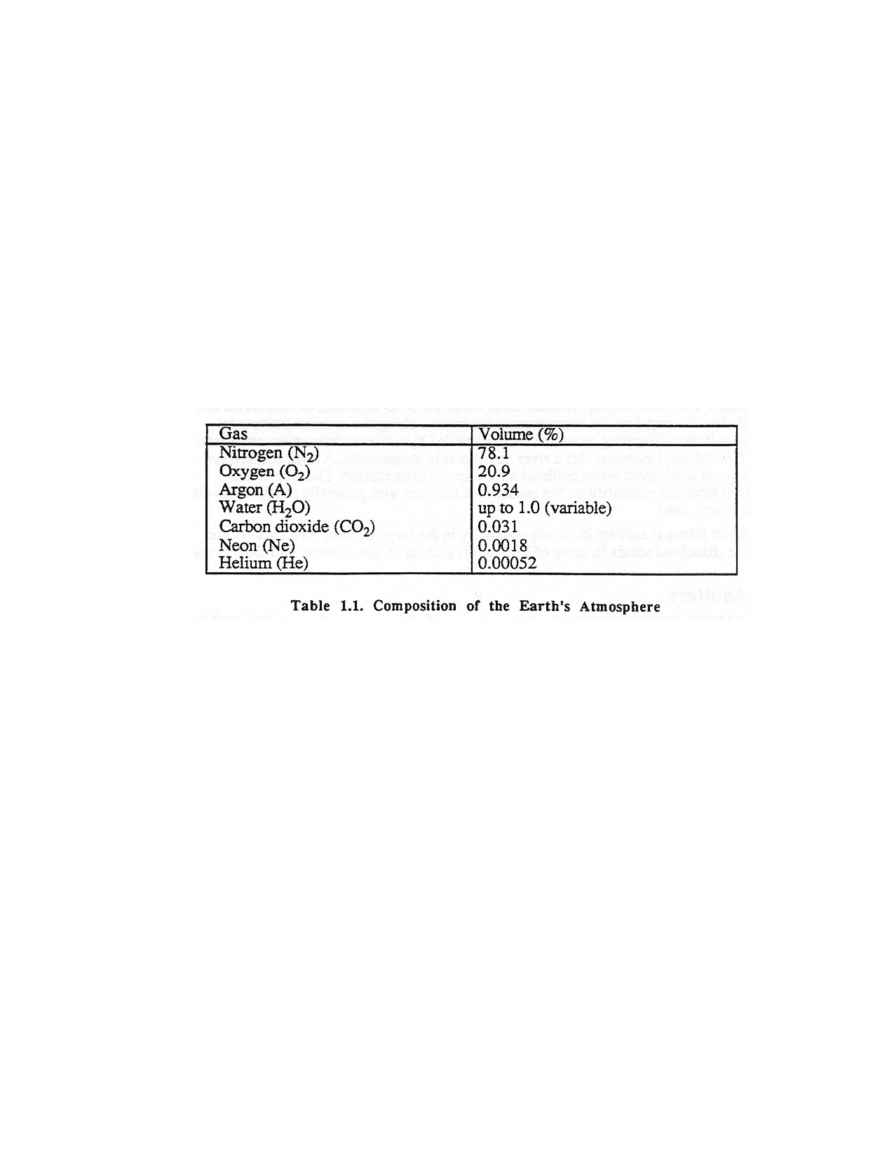
The composition of today's atmosphere is given in Table 1.1. The only component that appears to be
changing rapidly (in terms of man's time on Earth) is the carbon dioxide content. Since the start of the
Industrial Revolution, huge amounts of fossil fuels have been burned to provide energy for industrial
expansion and better living standards. In the burning of coal, oil, wood, and other fossil fuels, carbon
dioxide is released while oxygen is consumed. So much carbon dioxide has been released in the 20th
century that some scientists are worried that it is trapping more of the Earth’s heat in the atmosphere.
Rather than escaping into space, some of this extra heat is radiated back to Earth by the carbon dioxide
and may cause a world wide increase in temperature, leading to partial melting of the continental ice
sheets on Greenland and Antarctica and massive flooding of coastal communities. Another adverse
impact caused by burning large amounts of fossil fuels is the acidification of rainfall overlarge areas of
industrialized countries. Biological activity in lakes has either ceased or is limited seriously where the
Page 14 of 360
bedrock does not naturally buffer (neutralize) this rainfall; for example, in Canada, New England,
northern Minnesota. Florida, southern Norway, and Germany. In time, this phenomenon, called acid rain,
may increase significantly the acidic of near-surface groundwater.
All igneous and metamorphic rocks exposed at or near the Earth's surface are in an unstable chemical
and physical condition, and over geologic time these rocks breakdown into finer and finer components.
Destruction of rocks and the redistribution and deposition of the rock particles play a significant role in
producing three of the four major types of aquifer systems - alluvial, sedimentary, glacial, and
igneous/metamorphic. These particles are entrained and redistributed by the three agents of erosion -
wind, running water, and glacier ice. Running water is the most effective of these agents because it
operates continuously over most land areas of the Earth. Furthermore, it acts both as the primly agent in
the creation of alluvial aquifers and is a major force in building or altering other types of aquifers. Before
any major removal of a rock mass can take place, however, it must be broken down into particles that
can be carried by these agents of erosion. These processes are called rockweathering.
1.3. Weathering
Weathering is the in-situ physical disintegration and chemical decomposition of rocks in response to the
environmental conditions found at or near the Earth's surface. In general, the higher the temperature at
which a rock formed, the more unstable it will be at the Earth's surface. Granite, which crystallizes from
magma at approximately 1,110°F, is much more resistant to weathering than basalt, which forms at
2,190°F. Thus, the weathering rate depends on the temperature at which the rock formed, as well as
climatic conditions, the availability of water, its chemistry, and rate of movement, and the chemistry of
minerals making up the rocks. Because water has such a chemical affinity for almost all substances, and
because of its unusual physical properties, rock weathering proceeds rapidly in the presence of water.
Weathering is not only the first step in the production of alluvial and sedimentary aquifer systems, it is
also the process by which soils are produced.
Most rocks decompose or disintegrate by a combination of both physical and chemical processes.
Physical weathering is disintegration of rocks in place without associated major chemical change. During
physical weathering, Tacks are broken down into numerous small particles having a much larger
combined surface area than the original rock. In cold regions, physical weathering is the dominant
process; in the rest of the world, chemical weathering is far more important. Once the physical size of the
particles is reduced, decomposition is then accelerated by chemical attack on the larger surface area.
Chemical weathering of rocks is most effective in warm, humid regions where it is assisted by
organisms. Few common rock-forming minerals can resist chemical decomposition; quartz and
Page 15 of 360
muscovite mica are two notable exceptions. In general, most silicate minerals break down into both
relatively insoluble residues (such as clay minerals) and soluble substances which are carried away in
solution. Clay minerals are produced through decomposition of feldspars. Limestone, made up of
calcium carbonate, can be removed locally in solution if cartoon dioxide is present in percolating water.
Impurities contained in limestone, in the form of either clay or quartz particles, may remain after the
calcium carbonate is completely removed. In general all residual products of weathering are more stable
in the presence of air and water than were the rocks from which they came.
1.4. Erosion
The erosion cycle begins with weathering, when rocks are broken down into particles small enough to be
carried by running water. Rainwater forms sheetwash, which carries away the smallest particles;
sheetwash is water flowing sheet-like across a land surface and generally occurs only during heavy rains.
Sheetwash becomes channelized within short distances into rills or rivulets, occasionally into gullies,
then into small streams, and finally into rivers.
The most extensive alluvial water bearing strata are found adjacent to rivers flowing from mountainous
regions that have moderately dry climates. Sediment accumulations in the floodplains of rivers draining
these regions have coarse textures and may have thicknesses of 300 feet or more in certain areas.
Streams and rivers transport material in three ways: as bedload, as suspended load, and in solution.
Bedload comprises the coarser particles moved along the channel bottom by sliding, rolling, or saltation
jumping along the bed, propelled by impacts from other particles). Suspended load is weathered material
that a river transports in suspension. A river can always move a fine suspended load, even when bedload
movement is nonexistent. The size of the suspended sediment depends primarily on the gradient of the
river and generally ranges from claysized particles to coarse sand.
Dissolved material in rivers is carried in solution, usually in the form of ions. Riverwaters are
particularly high in dissolved solids in areas of low relief, such as in the Atlantic and Gulf Coast states.
1.5. Alluvial Aquifers
Rivers and streams build groundwater reservoirs consisting of alluvial deposits. Each year about 30,000
mi3 of water fails as snow and rain on the land areas of the Earth. About 30 percent of this water returns
more or less directly to the world's oceans by rivers and streams. As this water returns to the sea, it
erodes the landscape, deposits sediment such as sand and gravel along river courses, and carries the
remaining products of weathering to the sea. Landforms such as floodplains, alluvial fans, and deltas
form when rivers deposit miner than erode. Some of the sediment cannot be carried and is deposited as
alluvium on a floodplain in the middle reaches of the river. Floodplains form in the valleys excavated by
rivers. During peak discharges, the river goes over its banks, the velocity of the water decreases, and
suspended sediments are deposited. As the river meanders back and forth, sediments accumulate into an
actual plain. Wells drilled in this plain will almost always be successful because the sediments are of
similar size (well sorted) and the river provides continuous recharge to the sediments.
If the land surface is uplifted as the river approaches erosional maturity or base level falls because of
continental glaciation, the river cuts down into the floodplain deposits and leaves terraces along the
valley walls. Terraced valleys are erosional remnants created by periodic downcutting. Once saturated,
the sediments comprising the terrace generally become aquifers.
Page 16 of 360
Rivers build one other landform, alluvial fans, that can be important as an aquifer. Alluvial fans are
constructed at the base of mountain fronts in relatively dry climates when huge quantities of sediment are
carried to the dry valley floors by ephemeral rivers draining nearby mountains. Physical weathering
produces large amounts of loose rock material that can be entrained easily into the swift mountain rivers
that flow during the infrequent heavy rainstorms. Because the valley floors are nearly horizontal, the
sediment load is dumped abruptly as the rivers enter the valleys.
Alluvial fans are important to those interested in groundwater because, along with other valley
sediments, fans often represent the only extensive unconsolidated deposits in mountainous regions
capable of yielding high volumes of groundwater.
1.5.1. Hydraulic Characteristics of Alluvial Aquifers
The average grain size of river-deposited sediments can vary considerably; floodplain deposits may
consist of extremely fine silt, whereas coarse gravel or sand maybe more typical of alluvial fan deposits.
Floodplain deposits are usually fine grained, well rounded, and generally well sorted. Therefore, the
porosity is excellent but the hydraulic conductivity varies considerably, depending on the average grain
size. If the gradient of a river steepens or the discharge increases, the sediment will become coarser and
thus the hydraulic conductivity will be higher.
Floodplain deposits are quite uniform except at point bars (inside the meander bends) and at the bottom
of the rivers. When a river meanders, coarse sediment accumulates near or on the point bars. As the
meanders continue to migrate both laterally and downstream, finer grained (floodplain) material covers
the coarse sediment at the point bars. Similarly, bedload is buried during the meandering process. Wells
that intersect one or more of these coarse layers have higher yields than those in the finer floodplain
deposits.
Alluvial fan deposits are highly irregular in grain size and degree of grain roundness; they are built by
braided streams that continually deposit sediment as they flow over the fan surface. The constantly
changing paths of the braided streams produce deposits that have an irregular areal distribution. The
typical particles in an alluvial fan stream may not be as well rounded as those in a regular stream because
the weathered material may not be transported as far before deposition. Fine and coarse sediments are
intermixed, and thus the hydraulic conductivity and porosity of fan sediments may not be as good as in
river alluvium. It is particularly important, therefore, to drill test holes before designing and constructing
wells in alluvial fans. Because of their great thicknesses, these deposits can yield high volumes of water
to wells.
Another type of sedimentary deposit occurs in warm, shallow seas when the shells and secretions from
marine organisms form organic reefs of calcium carbonate. Great thicknesses of coral can grow if the
water deepens slowly. If the water deepens suddenly, the coral will die because of restricted light.
Sedimentation on top of the reefs is limited generally to clay particles if near shore, or it may include the
skeletal remains of tiny marine organisms if the water becomes deep enough.
Former beach deposits are the most valuable water storage sites because the volume of void space is
greatest. Beach sediment ordinarily can store more water per rock volume than any other type of
sedimentary rock. Void space in a new beach sand may be as high as 25 to 40 percent. In time, this space
may be reduced by settling and rearrangement of the grains, chemical precipitation, or heat, thereby
producing a rock formation called sandstone. The physical and chemical changes in sandstone resulting
from heat and high pressure produce a rock called quartzite which has virtually no void space.
Page 17 of 360
Sandstone formations are the most important reservoir rock for storing large volumes of groundwater.
Some individual sandstone layers are extensive; for example, the St. Peter Sandstone, a major aquifer in
the central United States, covers move than 290,000 mi2 and averages 80 to 160 ft in thickness.
1.5.2. Hydraulic Properties of Clay
When originally laid down, clay has high porosity. For example, clays now being deposited on the
Mississippi River Delta have 90 percent porosity. In time, compaction usually reduces the pore space
considerably. Although the volume of void space is relatively high in clays, the actual size of the voids is
extremely small. Water is strongly attracted to the large surface area of the clay particles and is less
controlled by the groundwater gradient. Thus, water does not move easily through clay sediment. When
sufficient and prolonged pressures are applied to clay deposits, the clay changes to shale, which is
weakly consolidated and breaks easily along depositional planes. When exposed to water during drilling,
some shales can swell to much larger volumes. In shale-rich areas, drilling operations can be severely
handicapped or even stopped by swelling shale. If greater heat and pressure are applied, the shale
changes to slate, a hard, dense rock with virtually no storage space for groundwater.
1.5.3. Hydraulic Properties of Calcium-Rich Deposits
Initially, inorganic calcium-rich deposits are quite massive and no large amount of chemical or physical
action is required to change them to rock after the deposition. Therefore, little void space exists for fluid
storage. This is not always true of coral reefs (organic calcium deposits), where initial void spaces occur
frequently but are spaced irregularly. Time and other factors, however do make calcium-rich deposits
more rigid and, in some cases, more dense. This type of sedimentary rock, known as limestone, is
inflexible and can easily crack when supported unevenly.
Under certain conditions, some of the calcium in limestone can be chemically replaced by magnesium
from sea water, either during deposition or after the rock strata formed. Limestone with high
concentrations of magnesium is called dolomite. It is not known with any certainty how this process
happens, but the addition of small amounts of magnesium causes a pronounced toughening of the rock.
Limestone does not initially offer much of a reservoir for storage, but through secondary solution many
deposits of limestone and dolomite can become large-capacity reservoirs for groundwater storage. Other
limestones are not cavernous and the only water in them exists in cracks and crevices.
1.6. Glacial Deposits
Glacial aquifers are the second most important category of aquifer systems. Although not as extensive as
aquifers found in sedimentary rocks, glacial aquifers occur throughout much of the highly populated
regions of northern United States, Canada, and northern Europe.
Pleistocene glaciers have been active over much of the world at various times during the past 3 million
years, especially in the Northern Hemisphere. The latest ice advances began about 80,000 years ago,
with the ice withdrawing about 8,000 to 10,000 years ago from most areas in the northern United States,
southern Canada, and Scandinavia. The most recent Pleistocene glaciers were not as large as some of the
earlier glaciers; therefore, they did not completely cover the landscape, but tended to follow topographic
lows in a manner similar to modern valley glaciers. These later glaciers left sediments called glacial drift
deposited irregularly in both areal extent and depth.
Page 18 of 360
Ice generally flows at rather uniform rates on flat topography; however, when the topography is uneven,
the ice will flow faster in the depressions. Entrainment of debris is greatest in these depressions and the
ice can deepen valleys to hundreds of feet below sea level. The deep depressions forming the Great
Lakes of North America and the fiords of Norway are extreme examples of glacial quarrying in
preexisting lowlands.
As the ice flows toward the terminus, glaciers continue to warm and eventually the ice near the margins
reaches either the pressure-melting temperature or 32°F. Bottom melting releases debris which is then
deposited on the underlying ground surface as the ice flows over it.
1.6.1. Moraine Formation
Rock debris carried well up in a glacier and not deposited as lodgement till from basal debris is
eventually transported to the glacier terminus. This heterogeneous material is canted in discrete debris
bands above the base of the ice. When the very end of an ice sheet becomes stagnant and temperatures
are sufficiently warm to melt the ice at approximately the same rate as it flows into the area, the active
ice flowing toward the front is forced upward at angles of 45 to 90 degrees before melting An ice-cored
moraine forms when debris melting out of the ice (till) begins to accumulate near the terminus. More ice
eventually becomes stagnant because of the overlying debris, and the active ice is forced to retreat.
Debris continues to melt out of the stagnant ice by undermelting and is thereby added to the till blanket.
In time, the ice core melts completely, leaving only the glacial sediment on the former land surface.
1.6.2. Depositional Features of Moraines
Unlike sediments deposited by other agents of erosion (wind and running water), glacier ice can entrain
and deposit all sizes of sediment in a single land form; huge rocks may be mixed with clay or fine sand.
Small lenses of sand and gravel occur frequency in moraines when the newly deposited till is reworked
by running water. These lenses are usually limited in size and occur irregularly throughout the moraine.
Thick layers of day without large fragments are also found in many moraines. Because clay is by
definition extremely well sorted, the presence of thick clay beds in a typically heterogeneous till matrix
should be explained. During the downmelting of an ice-cored moraine, many topographic low spots
develop. These are filled with water from time to time by superglacial streams (streams that flow on the
ice surface) or meltwater running down from the surrounding slopes into the depressions. Lakes may
exist for many years in these depressions if cracks do not occur in the ice underlying the lake bottoms.
During the melting season, superglacial streams continually carry sediments to the lakes. The finer or
clay-sized material is deposited in the offshore areas, and in time a thick clay bottom may form. Even
though a driving contractor may pass through 50 ft or more of clay, additional sand or gravel deposits are
likely to be found beneath the clay layer.
1.6.3. Outwash Deposits
During the time a glacier remains in contact with its moraine, meltwater rushing off the clean ice courses
through the moraine and picks up sediment. Because the meltwater is free of sediment before reaching
the moraine, the transporting capability of these waters is high. Furthermore, the gradient of meltwater
rivers is quite steep, usually much steeper than in rivers on land adjacent to the terminus, thus giving
them additional capacity to remove sediment from the moraines.
Page 19 of 360
When climatic conditions are favorable for rapid melting, meltwaters entrain gravel-sized debris. Most
of this gravel is carried as bedload, that is, the individual stones are transported along the bottoms of
rivers and streams. Once the rivers reach the nonglaciated areas outside the terminus where the gradient
is much lower, the rivers can no longer transport all the material picked up in the moraine and thus begin
to deposit some of it in their channels. Deposition continues until the rivers have the capacity to carry all
of the remaining load. Clay-sized materials are usually carried far downstream by the meltwater rivers
and deposited away from the outwash aprons. In general, the average particle size in each sediment layer
tends to diminish downstream from the moraine.
In time, stratified sand and gravel deposits called outwash build up in front of the moraine. Usually, the
sediment aprons extend some 6 to 12 mi outward from the terminus.
Outwash deposits and till sequences are also laid down between moraines by advancing or retreating ice
fronts. During a long-term withdrawal, a glacier is periodically interrupted in its retreat by sudden surges
of forward movement. Once the advancing ice reaches its new limit, another stillstand of the ice front
may occur, and another moraine is created. Several repetitions of advance and retreat may occur before
the ice withdraws at the conclusion of the glacial episode. Thus, multiple moraines occur commonly in
the terminal areas of many glaciers.
1.6.4. Recognition of Moraines and Outwash Plains
Moraines deposited during the last 10,000 to 35,000 years are relatively easy to identify from
topographic maps or by judicious use of a highway map showing lakes. Moraines are generally
characterized by numerous abrupt changes in surface elevations over short horizontal distances. The
characteristic hummocky or knolly topography develops by uneven deposition of the superglacial debris
during melting of the ice core. If the climate is wet, moraines generally have numerous lakes and
swamps which form in the abundant undrained depressions. Outwash plains characteristically show only
small differences in relief and are marked by shallow, well-rounded lakes. They are recognized easily in
the field and on topographic maps by their essentially flat topography. When using a highway map, it
must be assumed that the glaciers came from a northerly direction (in the Northern Hemisphere);
therefore, the major outwash plains associated with particular moraines must be south of the moraines.
Exceptions to this rule do occur, however, especially in glaciated regions near mountains.
1.6.5. Hydraulic Properties of Glacial Deposits
Two types of glacial sediments are generally recognized: till and outwash. Till has been subdivided into
two types: lodgement till and ablation till. Lodgement till, often called hardpan by drillers, consists of
glacial sediment deposited on the ground beneath the ice when the glacier temperature approaches 32°F.
Ordinarily, individual layers of lodgement till are highly compressed, poorly drained, clay-rich sheets
from 3 to 30 ft thick; multiple ice advances may increase the total thickness to 300 feet or more. Ablation
till consists of material released through surface melting at the glacier terminus. Ablation till is loosely
consolidated, clay poor, and contains all sizes of mosey angular to semi-rounded material. This type of
till deposit forms huge curvilinear moraine complexes that are found in many northern areas of the
United States and Europe.
Till, especially clay-rich till, has lithe pore space because abundant small particles fill in the voids
between the larger grains. Thus, there is little storage area for significant volumes of groundwater in till.
Page 20 of 360
Outwash consists of well-stratified and well-sorted silts, sands, and gravels. Outwash sediments are more
or less uniform in grain size and contain particles that are usually well rounded, loosely packed, and
relatively uncemented; thus, porosities in outwash deposits are unusually high.
Two constructional features of outwash plains are significant. First, the thickness of outwash can vary as
much as the relief in the former landscape. In some glaciated regions of North America, old preglacial
valleys of the Mississippi, Minnesota, and Ohio Rivers are filled with 250 to 300 ft of primarily outwash
material, whereas the adjacent upland surfaces are covered with only 15 to 45 ft of sediments.
1.6.6. Miscellaneous Glacial Deposits
Two other sediment types related to glacial activity are also potential reservoirs for groundwater. The
first is loess, a nonstratified and unconsolidated sediment consisting mostly of silt-sized particles of
quartz and feldspar. These particles are picked up by wind from outwash plains and deposited downwind
as loess at varying distances from the ice fronts. Loess deposits occur extensively because of the
abnormally high wind velocities associated with ice fronts, and the ready supply of silt-sized material
continuously deposited by meltwater on the outwash plains. Loess found near its source areas may be
150 ft or more thick, but the deposits thin rapidly in the downwind direction.
Valley-train deposits, consisting of coarse sand and gravel, are the second type of sediment indirectly
associated with glacial activity. As indicated above, rivers draining the ice fronts carried huge quantities
of outwash sand and gravel. At first, the local rivers were unable to carry all the sediment for any great
distance, even during the high discharges of the summer season and despite the steeper gradients brought
about by the reduction in sea level. In time, the river gradients near the ice fronts were steepened
sufficiently by depositional processes for the rivers to carry the available load. Eventually, coarse sands
and gravels were transported hundreds of miles downstream via major river systems; some of these
sands were transported all the way to the Gulf of Mexico. Today, these valley-train deposits, although
localized to a great extent in buried valleys and along existing rivers, represent significant sources for
groundwater.
1.7. Rock Aquifers
Locating adequate water supplies in bedrock is extremely difficult because the physical makeup of
igneous and metamorphic rocks is generally unfavorable for storage or transmission of economically
useful volumes of water. Nevertheless, much of the world's population lives on lane consisting of these
rock types, and whatever water supplies are available must be utilized.
The major intrusive igneous rock types are granite, diorite, and gabbro. As originally formed, these rocks
do not have the necessary hydraulic characteristics required for adequate water supplies. They have a
solid structure which precludes both significant water storage and transmission. Extrusive igneous rocks,
on the other hand, commonly possess physical features that can provide reasonable-to-large volumes of
water. Common extrusive rock types include basalt, andesite, rhyolite, and loosely consolidated volcanic
deposits. Unfortunately, extrusive rocks constitute only small portions of the igneous and metamorphic
rock areas.
In general, any rock underlying recent glacial drift has a weathered zone. This zone is thickest in the low
areas of the preglacial landscape and thinnest on the high areas. In this zone, drillers can expect to
encounter marl (calcium-rich clay), iron-rich crusts representing old soil zones, and weakened quartzite,
Page 21 of 360
sandstone, and marble with numerous small-to-large cavities that may be arranged along old depositional
surfaces in the original rock. In almost every case, a mushy clay zone of varying thickness exists
between the glacial deposits and the more competent underlying weathered bedrock.
Massive basalt flows (extrusive rocks) originate in the interior of some continents as a result of rifting
events or so-called hot spots in the upper mantle. Basalt may have high porosity and hydraulic
conductivity, depending on the way individual flows cooled or the length of time between flows. The
openings in a sequence of basalt flows occur in several ways: as cracks formed during cooling where the
hardened crust of a basalt flow has collapsed, as vesicles (gas holes) near the top of each flow, in empty
lava tubes, and in alluvial sediments laid down between flows. Vesicles near the top of individual lava
flows are a mayor cause of high porosity and hydraulic conductivity. Wells in basalt have a much greater
yield potential than do those in intrusive rocks.
In summary, the success rate for wells in igneous and metamorphic terrains is low. Even when elaborate
exploratory methods are employed, the yields from wells may be disappointingly small, and dry holes
are common.
CHAPTER 2.
OCCURRENCE AND MOVEMENT OF GROUNDWATER
The majority of the fresh water in the conterminous United States is found in the groundwater. Estimates
indicate that groundwater represents approximately 85% of our total fresh water. Approximately half of
this groundwater is near surface with an average detention time of 200 years. The other half is much
deeper with a detention time of 10,000 years. The second largest source of fresh water is the water found
in the Great Lakes.
When precipitation falls to the earth in the form of snow, rain, or hail, some portion of it is intercepted
by trees, plants, and buildings. If the storm is brief or of a low-intensity, this water will be evaporated
back into the atmosphere.
Page 22 of 360
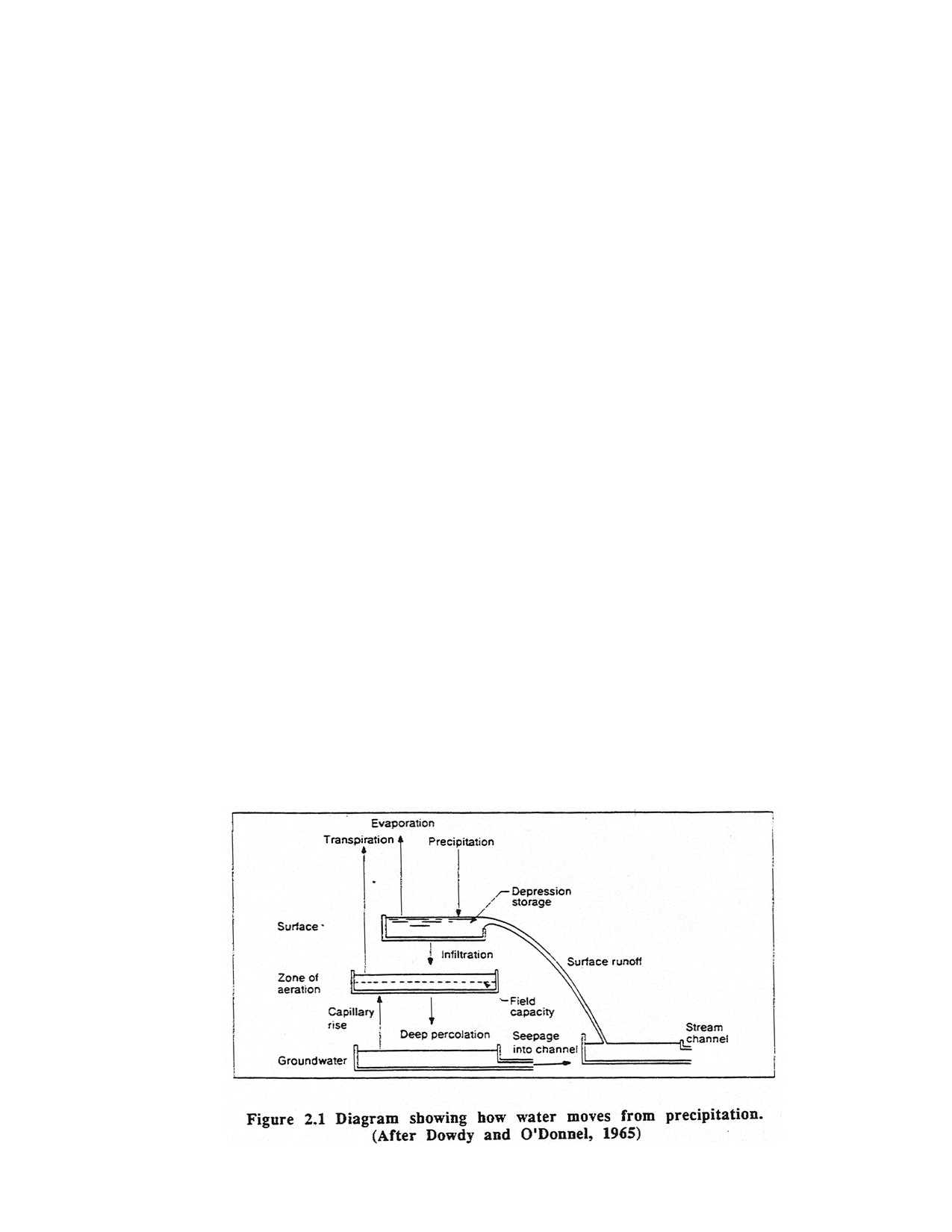
During heavier precipitation, water (liquid or frozen) does reach the ground surface and can follow
several different paths as shown in Figure 2.1. The water that flows overland is called surface runoff. It
usually combines with other surface water to form a steam or river. Some of the water may infiltrate the
soil and seep downward until it reaches the groundwater table. Some of this water may eventually seep
into a stream or river. The relative amounts of surface runoff to infiltration depends on the amount of
water already present in the soil. During severe storms (or in the north during the early spring when the
ground is frozen) little or no water may infiltrate the ground. These are the times when flooding is likely.
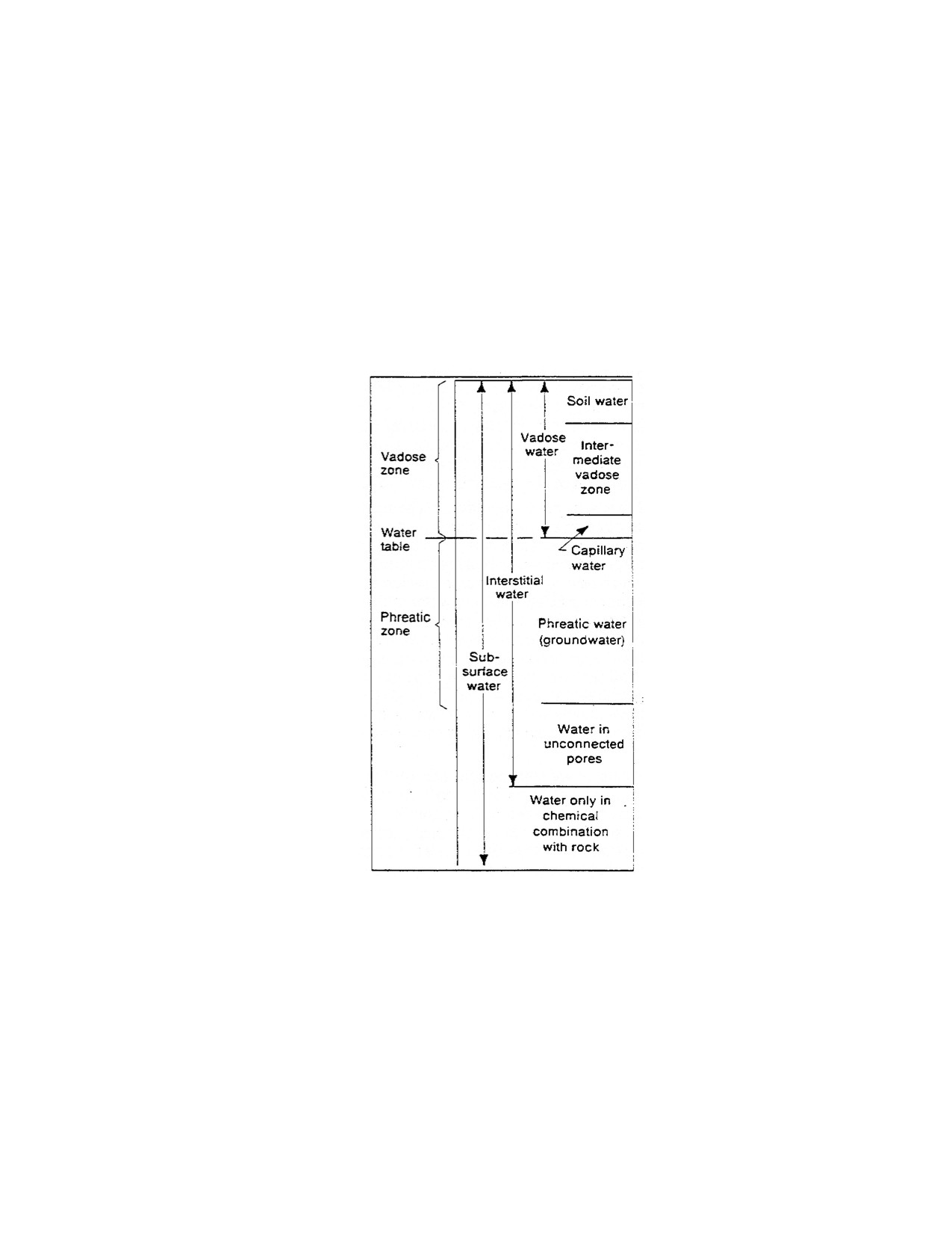
Typically water is introduced to the soil by infiltration and stream flow, however once the water enters
the soil, it exists in several different modes as shown in Figure 2.2. This commonly used classification
indicates that water is found in two major zones in the soil--a zone of vadose water and a zone of
phreatic water.
Figure 2.2. Classification of subsurface water. (After Davis and DeWiest, 1966)
In the vadose zone, three separate types of water exist: soil water, intermediate vadose water, and
capillary water. The soil water is the primary water used by plants. The depth of the soil water zone
varies from 3 to 30 feet. The intermediate vadose water zone merely represents the region between the
soil water zone and the capillary water zone. The capillary water zone (sometimes called the capillary
fringe) is the zone where water is literally pulled upward by capillary action (which depends on the
surface tension between water, soil particles, and air). The height of capillary rise depends on the size of
the smaller grains of the soil. Capillarity is not effective in coarse grained soils whereas water can be
pulled up 30 feet or more in some clays.
The groundwater table lies at the bottom of the capillary zone and separates the vadose water zone from
the phreatic water zone.
Page 23 of 360
If a well were drilled through the vadose zone, into the phreatic zone, the water level in the well would
mark the location of the groundwater table and the top of the phreatic zone. Water below the
groundwater table is generally called groundwater. Davis and Dewiest refer to this water as phreatic
water meaning water that enters freely into wells. This handbook will use groundwater instead of
phreatic water, referring to water that can be removed by wells. It is important to note, groundwater
therefore does not include water above the groundwater table.
An aquifer is historically defined as a geologic formation that will yield useful quantities of water for a
water supply. The term is relative to other available sources of water and to the quantity of water
required. The nearly synonymous terms water-bearing material and water-bearing zone may be defined
in the broader sense as being any geologic formation or stratum, consolidated or unconsolidated, or
geologic structure, such as a fracture or a fault zone, that is capable of transmitting water in sufficient
quantity to be either of use or of concern. Such a formation contains pores or open spaces between the
miners grains that are filled with water. The ability of a formation to hold and transmit water depends on
the size and number of pores in the geologic formation. Some formations may have a large pore volume
(some clays for example) however the are unable to transmit water due to their small pore openings and
therefore are not classified as aquifers. Ordinarily a clay or shale formation is nearly impermeable and is
called an aquiclude. Formations which yield some water but not enough to meet modest deems are
termed aquitards. These terms are not absolute and may depend on the availability of water in a given
region.
Water exists in aquifers under two different physical conditions. The most common condition is when
the water table is exposed to the atmosphere (via the pores of the overlying soil). This type of aquifer is
called an unconfined aquifer or water table aquifer. The water table is the upper surface of the zone of
saturation in an unconformed water-bearing material. The water table is the imaginary surface in an
unconfined water-bearing material along which the hydrostatic pressure is equal to the atmospheric
pressure. In coarse grained soils, the water table is near the top of the saturated zone. A perched water
table occurs where a layer or lens of low permeability material lies within an unsaturated permeable
material and restricts the downward movement of water sufficiency to create a localized saturated zone
above the general water table. In certain soils a layer of low permeability occurs in the subsoil that
prevents downward percolation of water sufficiently that during wet periods a temporarily saturated zone
develops. The top of this intermittently saturated zone is referred to as the seasonal high water table. It
may or may not be perched. A perched zone of saturation that is sufficiently permanent and transmissive
may be called a perched aquifer.
Although subsurface water does not occur in underground streams (except in some cavernous
formations) as popularly misconceived, groundwater flow is variable throughout the subsurface. The
natural variability of rocks and soils causes variations in hydraulic conductivity both within a
water-bearing material and from one water-bearing zone to another. In unconsolidated materials where
primary porosity is dominant, groundwater flow is generalized throughout the material because the
interstices are numerous and close together. However, within a generally fine grained material there may
be coarser layers through which water can move more rapidly and in larger quantities than it can through
the material as a whole. Bedrock may be impermeable itself, but water moves through it in fractures and
other such openings called secondary porosity. Groundwater flow is not so generalized in this material
where the flow paths are more widely spaced. In addition there are areas within rock formations where
fractures are concentrated or are more open so that water can move more readily through these areas. It is
this type of situation that has supported the notion of underground streams.
Page 24 of 360
Groundwater may also occur under confined conditions. Groundwater that is confined is isolated from
the atmosphere at the point of discharge by aquicludes. The confined aquifer generally has higher
pressures than atmospheric acting on it causing the water in a well drilled into the formation to rise
above the levy of the formation. Artesian is equivalent to confined. It can refer to either the
water-bearing material, as in confined aquifer, or to the water confined in the material, as in artesian
ground water. The water in a confined material also may be referred to as occurring under confined
conditions or artesian conditions. Confined water is held in the water-bearing material by an overlying
material of low permeability called the confining layer. Confined water will rise in a well to a level
above the top of the water-being material, defining the potentiometric surface at that point. If the
potentiometric surface is above the land surface, the well will be a flowing well.
An aquifer performs two important functions—storage and transmission of water. The water in the pore
spaces is constantly moving at rates ranging from feet per day to feet per year. The shape, size, volume,
and connectivity of the pores and openings affect the ability of the formation to store and transmit water.
Two properties of an aquifer that affect its ability to store water are porosity and specific yield. The
porosity is defined as the ratio of the volume of the pore space to the volume of the geologic material. It
is expressed quantitatively as the ratio of void space to the total volume of porous material. It is stated as
either a decimal fraction or as a percentage. and is dimensionless. For example, if 1 ft3 of sand contains
0.25 ft3 of open space or pores, its porosity would be 25%. Primary porosity refers to the original
interstices created when a material, such as rock or soil, was formed. Typically, primary porosity is the
pore space between grains, pebbles or crystals. Secondary porosity refers to interstices created after a
material was formed. Examples are fractures (joints and faults) openings along bedding planes, solution
cavities, cleavage, and schistosity. Secondary porosity is the dominant form in consolidated materials
such as well cemented and strongly indurated sedimentary rocks and in most and metamorphic or
crystalline rocks.
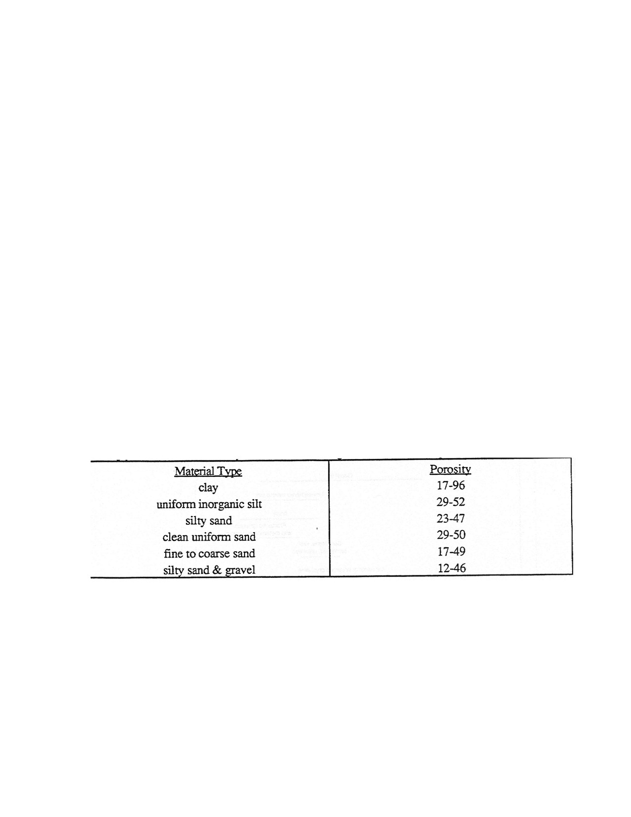
Table 2.1 Typical Porosities of Geologic Materials
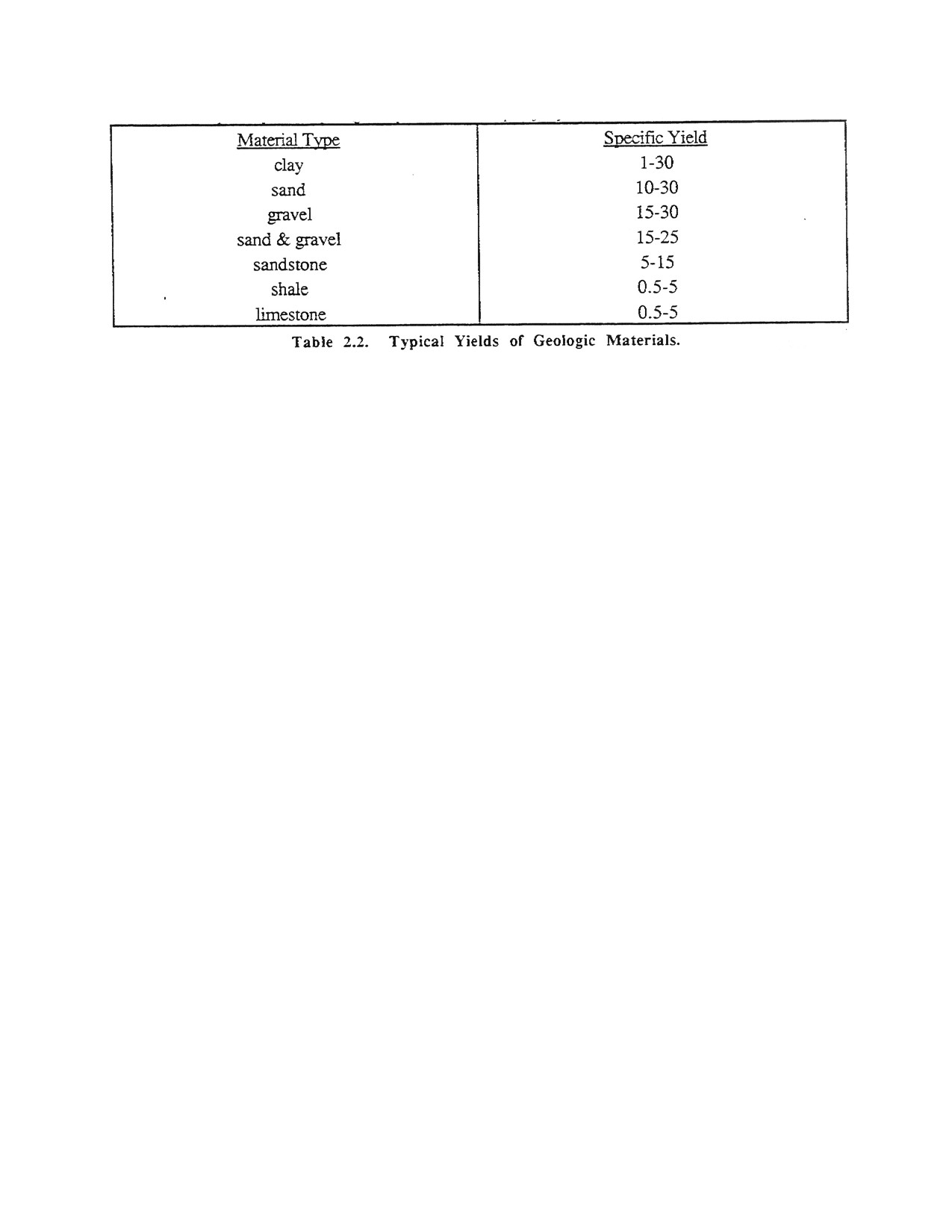
Table 2.1 provides typical values for common geologic materials. Although the porosity represents the
volume of water an aquifer can hold, it does not represent how much water the aquifer will yield.
An example is needed to explain this concept. When water is drained from a saturated sponge by gravity,
the sponge releases only a smell portion of the total volume of water stored in its pores or openings. This
is true of an aquifer as well. The quantity of water that a unit volume of unconfined aquifer yields up to
gravity is called its specific yield.
Page 25 of 360
The amount of water that a unit volume of aquifer retains after gravity drainage is called its specific
retention. The porosity of an aquifer is the sum of the specific yield and the specific retention. Specific
yields are not determined for confined aquifers because the water is not completely removed from the
pores during pumping.
2.1. Permeability
The transmission function of an aquifer is related to its ability to conduct water. The property of an
aquifer directly related to this ability is called its coefficient of permeability or hydraulic conductivity.
The permeability of an aquifer is governed by the size, shape, and connectivity of the pores, as well as
the properties of the fluid moving through the pores. If the pores are small and not well connected, the
ability of a fluid to flow through the aquifer will be low and the aquifer will have a low permeability.
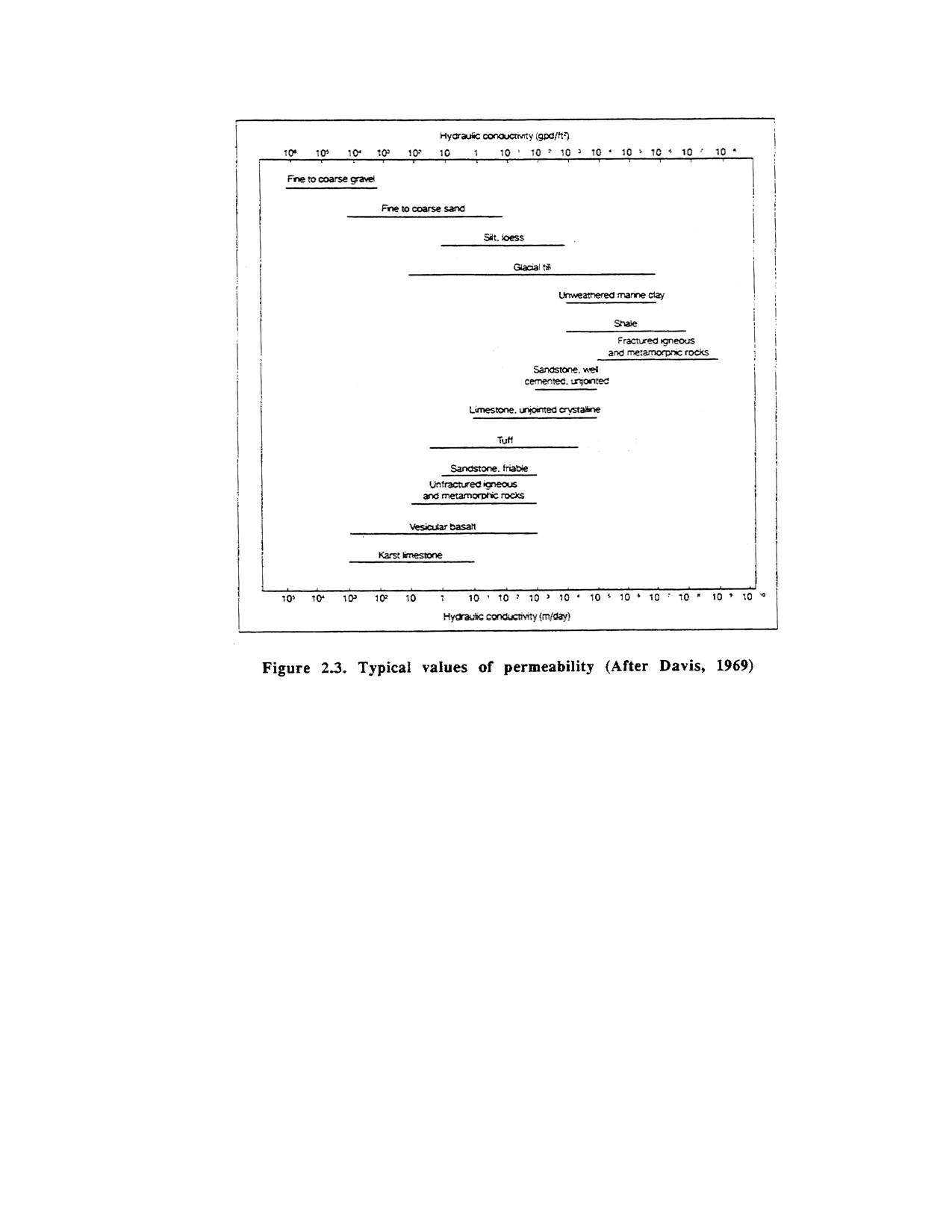
Typical values of the coefficient of permeability are shown in Figure 2.3.
Page 26 of 360
These values are used to predict how much fluid will flow in a given time through a cross section of
aquifer under a specified hydraulic gradient. The gradient is related to how much pressure is available to
cause the water to flow in the aquifer. The higher the gradient, the more water that will flow through the
aquifer. According to D'Arcy (1856), if the gradient is doubled, then the amount of water that will flow
will be doubled The D'Arcy equation used to mathematically describe D’Arcy’s law is shown in
equation 2.1.
q = kiA
(2.1)
where q = discharge (volume/time), k = coefficient of permeability (length/time), i = gradient
(length/length), and A = area through which fluid is flowing (length2).
2.2. Transmissivity
The coefficient of permeability times the aquifer thickness equals the transmissivity. This value describes
the rate of flow through a vertical section of a aquifer under a unit gradient. The transmissivity is
obtained by pumping tests, by laboratory tests, or by estimating the permeability from grain size
measurements. Of these methods, the pumping test proves to be the most accurate.
2.3. Groundwater Flow Velocities
The magnitude of groundwater flow velocities is of little interest to persons primarily concerned with
water yields from a well. However, with the advent of groundwater contamination, the ability to assess
Page 27 of 360
the velocity of a contact moving in the ground has become of vital importance. From D'Arcy's law,
equation 2.2 can be derived.
v = ki/ŋ
(2.2)
where v = velocity of flow through the pores (length/time), k = coefficient of permeability (length/time),
i = gradient (length/length), and ŋ = porosity. Frequently, tracers such as dyes or salts are used to
physically measure this velocity.
2.4. Collection of Hydrogeologic Data
Hydrogeologic data are applicable to a variety of problems both directly and indirectly affecting the
success of any project. Subsurface water can affect the stability of structures, the costs of construction,
the costs of maintenance, and the effects of structures on neighboring properties. To better understand
groundwater and its movements the devices used to determine groundwater movement must be known.
2.4.1. Observation Wells
An observation well is a hole that has been bored into the ground to some depth into the saturated zone,
and fitted with a casing or a well point in order to maintain an open hole over a period of time. Wells
may be drilled purely as observation wells; however, in common practice test borings are connected to
observation wells. Existing water wells in the area can also be used.
Observation wells are most often used to measure water levels. These measurements may be made
periodically by hand or automatically by a continuous recorder. A common hand instrument is the steel
tape. A second hand instrument is a simple, mechanical sounding device attached to a surveyor's tape.
The device could be a 4-inch length of 0.5-inch diameter tubing, capped at one end and open at the other.
The capped end is attached to the tape by means of a swivel clip. As the tape with the sounding device is
lowered into the observation well, a distinctive sound is heard when the open end of the device contacts
the water surface. A third hand instrument is the electric probe, which consists of two wires and an
ammeter that registers a current when the circuit is closed by the ends of the wires being immersed in the
water. This instrument can be used with at. accuracy equivalent to the steel tape, and it is more
convenient than the tape when water depths exceed 100 ft.
Observation wells are also used to measure the water-bearing characteristics of the materials that they
penetrate. Borehole permeability tests are conducted during drilling of the observation well as the hole is
advanced. These tests may also be conducted after the boring is completed but before the well is
installed. After the observation well is completed, pumping tests can be conducted. The observation well
may be used either as a pumping well, for water level measurements during pumping of another well, or
for both purposes alternately.
Finally, an observation well may be used to obtain samples of water for chemical analysis to be used in
water quality studies. Water samples should be as representative as possible of water as it occurs in the
water-bearing material of interest. The chemistry of the water standing in a well will change quite
rapidly due to reduced pressure in the well, greater exposure to air, contact with casing and screening
materials, and other factors. Therefore, water should be removed from an observation well prior to
sampling in order to remove any stagnant or unrepresentative water.
Page 28 of 360
Some judgment is involved in how long to pump a welt or otherwise remove water, before sampling, but
a widely used standard is to remove an amount of water equal to at least degree times the volume of
water standing in the well. Various conditions frequency make it impossible or impractical to purge a
well to the desired extent. The extreme case is when a very low-yielding material is being investigated.
Then it may be difficult to obtain even enough water at a single sampling to perform the desired
analyses. ID any case when a sample is obtained, the duration and rate of water removal prior to
sampling should be recorded along with all other conditions of the well and the water, such as whether or
not the well is actively used and last usage, depth to water before and after purging and sampling, depth
of pump intake or the depth to which other sampling device was lowered, clarity of the water before and
after purging and sampling, water temperature, and so on. Water samples should be analyzed as soon
after sampling as possible.
2.4.2. Piezometers
A piezometer is a specialized type of observation well designed to determine pore pressure in soil, rock,
or other porous material. The piezometer differs from the general observation well in that it is open only
to a particular point in the material so that the water level in the piezometer indicates the hydraulic
pressure at that point. A general observation well on the other hand is usually open to some thickness of
the porous material and is indicative of the average potential in the material over that interval. Pore
pressure is determined by subtracting the elevation head (the distance of the point of measurement above
some arbitrary datum) from the hydraulic pressure (the height of the potentiometric surface above the
same arbitrary datum). The potentiometric surface can be measured in an adjacent observation well or in
a second peizometer at the water surface.
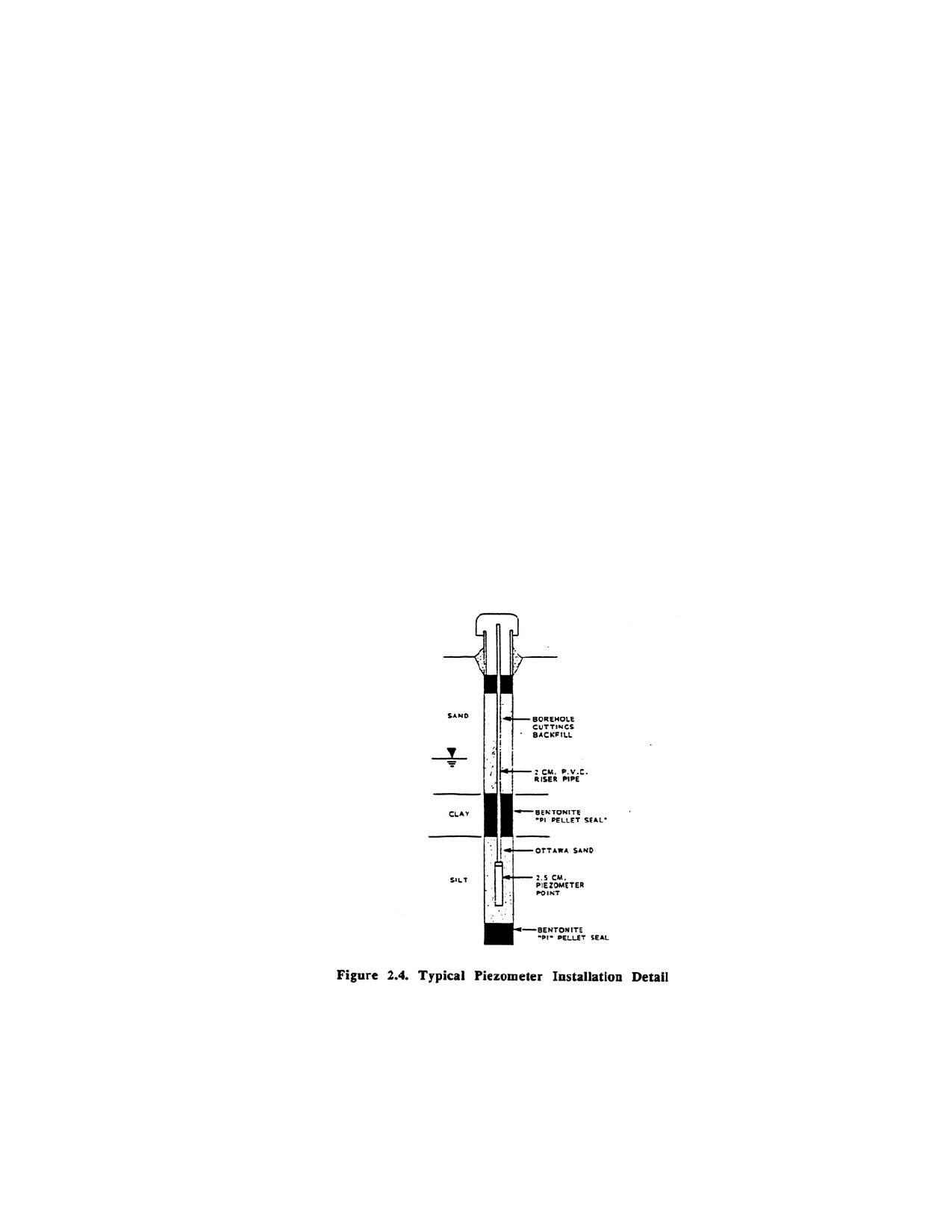
A type of piezometer installation is shown in Figure 2.4. A piezometer may consist of a pipe or casing
that is drilled or driven to the desired depth of measurement .With the screened section only at the
bottom, water can enter only at the depth of interest and will rise in the pipe in accordance with the
hydraulic pressure at that depth. More sophisticated types of piezometers consist of a porous tip sealed
into a soil layer and connected to the surface by fluid-filled tubes. Several of these devices may be placed
at various depths in one boring. For more accurate leadings, a mechanical or electrical pressure
Page 29 of 360
transducer is placed in the porous tip. This type of piezometer will only measure pore pressures in the
saturated zone.
2.4.3. Potentiometric Surface
Potentiometric surface is an imaginary surface connecting points to which water would rise in tightly
cased wells from a given point in an aquifer. Potentiometric surface replaces the older term piezometric
surface.
A basic objective of groundwater analysis is to define the potentiometric surface. This is done by
plotting water elevations from observation well data, and drawing lines of equal elevation, which are for
practical purposes, equipotential lines. A minimum of three points of elevation is required to define a
plane, but this will yield only the roughest approximation of the potentiometric surface, which is
normally an irregular curved surface. The water table is the Potentiometric surface in an unconfined
water-bearing material. It usually more or less reflects the surface topography, whereas the
potentiometric surface in a confined material may have little or no resemblance to surface topography.
Thus, many elevation points (observation wells) are desirable to clearly define the potentiometric
surfaces.
The potentiometric surface map shows where recharge and discharge occur, and the directions of
groundwater flow. Water flow is at right angles to the equipotential lines, from areas of high potential to
areas of low potential.
Water levels may vary with time and in venous cycles. Thus, it is important to obtain water-level
measurements in all observation wells as close to the same time as possible.
CHAPTER 3.
WELL HYDRAULICS
3.1. Definition of Terms
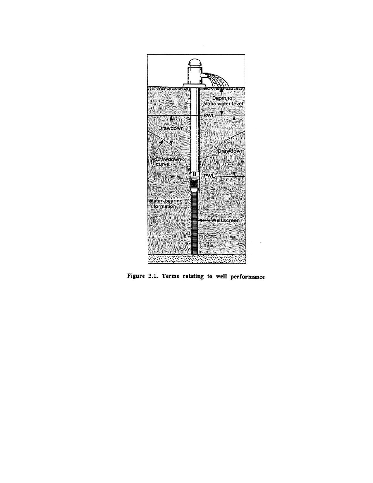
It is important to understand clearly the meaning of common terms related to pumping wells. Definitions
are presented below, and several terms are defined diagrammatically in Figure 3.1.
Page 30 of 360
3.1.1. Static Water Level
This is the level at which water stands in a well or unconfined aquifer when no water is being removed
from the aquifer either by pumping or free flow. It is generally expressed as the distance from the ground
surface (or from a measuring point near the ground surface) to the water level in the well. For example,
when the static water level in a well is 15 ft. it means that water stands 15 ft below the measuring point
when there is no pumping. For an artesian well which flows at the ground surface, the static water level
is expressed as a height above the ground surface. When artesian flow is stopped or contained at the
ground surface, the pressure developed is referred to as the shut-in head. If the well has a shut-in head of
3 psi at the surface, it means that the confining pressure will cause the water to rise 7 ft in a pipe
extending above the ground surface.
3.1.2. Pumping Water Level
This is the level at which water stands in a well when pumping is in progress. In the case of an artesian
well, it is the above ground level at which water is flowing from the well. The pumping water level is
also called the dynamic water level as measured in the well.
3.1.3. Drawdown
Page 31 of 360
Drawdown is the difference, measured in feet or meters, between the water table or potentiometric
surface and the pumping water level. This difference represents the head of water (force) that causes
water to flow through an aquifer toward a well at the rate that water is being withdrawn from the well. In
the unconfined case, the head is represented graphically by the actual water level at a point along the
drawdown curve. In confined conditions, the drawdown curve represents the pressure head at that point.
To differentiate these two types of drawdown, all diagrams in this manual show the water table for
unconfined conditions as a solid line and the potentiometric surface for confined conditions as a dashed
line.
3.1.4. Residual Drawdown
After pumping is stopped the water levy rises and approaches the static water level observed before
pumping began. During water level recovery, the distance between the water level and the initial static
water level is called residual drawdown.
3.1.5. Well Yield
Yield is the volume of wafer per unit of time discharged from a well, either by pumping or free flow. It
is measured commonly as a pumping rate in gallons per minute or cubic meters per day.
3.1.6. Specific Capacity
Specific capacity of a well is its yield per unit of drawdown, usually expressed as gallons of water per
minute per foot (gpm/ft) of drawdown or cubic meters per day per meter of drawdown, after a given time
has elapsed, usually 24 hours. Dividing the yield of a well by the drawdown, when each is measured at
the same time, gives the specific capacity. For instance, if the pumping rate is 1,000 gpm and the
drawdown is 30 ft. the specific capacity of the well is about 33.3 gpm per ft of drawdown at the time the
measurements were taken. Specific capacity generally varies with duration of pumping; as pumping time
increases, specific capacity decreases. Also, specific capacity decreases as discharge increases in the
same well. The reasons for decreasing specific capacity are discussed later in this chapter.
Static water level pumping water level, drawdown, and residual drawdown apply similarly to a pumped
well or other nearby wells and observation wells. For example, if the water level in an observation well
located 80 ft from a pumping well dropped 3 ft as a result of the pumping, this lowering in the
observation well is called its drawdown.
3.2. Nature of Converging Flow
The water level in the vicinity of a pumped well under unconfined conditions is lowered when pumping
begins, with the greatest drawdown occurring in the well. As the pomp removes water, an area of low
pressure develops near the well bore. Because the water level is lower in a pumped well than at any place
in the water-bearing formation surrounding it, water moves from the formation into the well to replace
water being withdrawn by the pump. The pressure (force) that drives the water toward the well is called
the head, which is the difference between the water level inside the well and the water level at any place
outside the weld. At some distance from the well a point is reached where the water level is essentially
unaffected. This distance varies for different wells. It also varies for the same well depending on both the
pumping rate and the length of time the well is pumped.
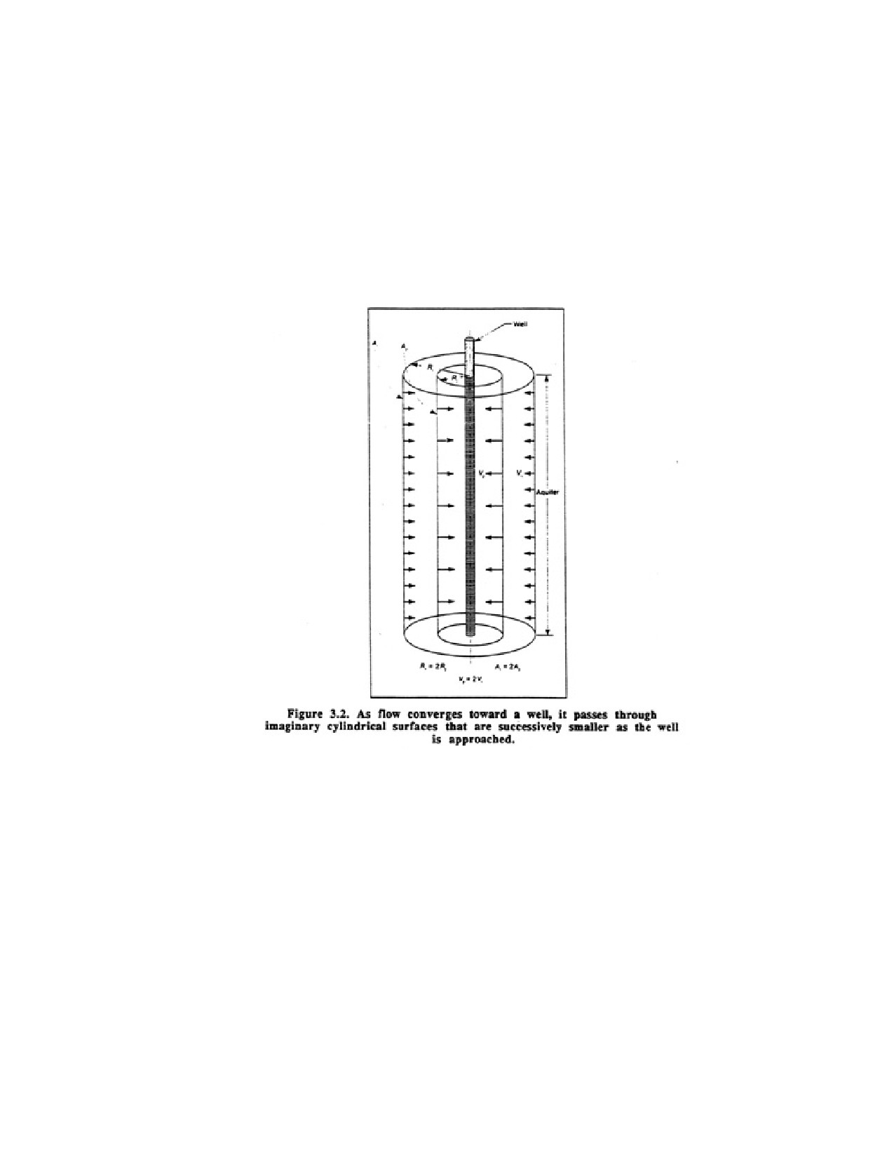
Page 32 of 360
In confined formations, the saturated thickness of the aquifer is generally not reduced during pumping.
Hydrostatic pressure, however, is reduced in the aquifer, and the pressure drop is greatest at the well
bore. The pressure drop is directly analogous to the dewatering effect in unconfined aquifers.
During pumping, water flows toward the well from every direction. As the water moves closer to the
well, it moves through imaginary cylindrical sections that are successively smaller in area. Thus, as the
water approaches the well, its velocity increases. In Figure 3.2, A1 represents the area of a cylindrical
surface 100 ft from the center of the well and A2 represents the area of a similar surface 50 ft from the
well. Because A1 is twice A2 and
the same quantity of water flows toward the pumped well through both cylinders, the velocity V2 must be
twice V1.
Darcy's law indicates that the velocity of flow through porous media varies directly with the hydraulic
gradient. As the hydraulic gradient increases, velocity increases as flow converges toward a well. As a
result, the lowered water surface develops a continually steeper slope toward the well. The form of this
surface resembles a cone and is caned the cone of depression. When pumped, all wells are surrounded by
a cone of depression. Each cone differs in size and shape depending upon the pumping rate, pumping
duration, aquifer characteristics, slope of the water table, and recharge within the cone of depression of
the well.
Figure 3.3 shows two cones of depression around pumped wells that illustrate how transmissivity of an
aquifer affects the shape of the cone. In a formation with low transmissivity, the cone is deep with steep
sides and has a smog radius. In a formation with high transmissivity, the cone is shallow with flat sides
and has a large radius. The explanation for these different cone shapes is clear, for greater hydraulic head
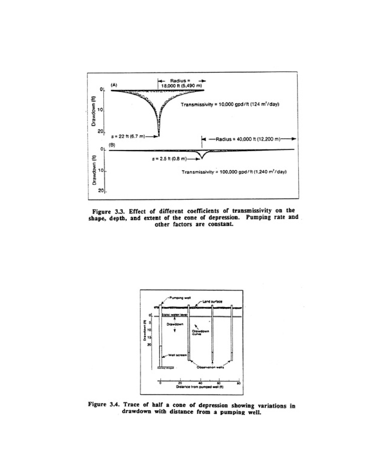
Page 33 of 360
(feet of head) is required to move water through a less permeable formation than through a more
permeable formation.
Figure 3.4 shows the levels at which water would be found in observation wells drilled at various
distances from a pumped well. Only one side is shown; the other side is similar. This curve is called the
drawdown curve and represents the lower limits of the cone of depression. In an unconfined aquifer, it
represents the level to which the formation remains saturate In a confined aquifer, it represents the
hydrostatic pressure in the aquifer. Drawdown at any given point is the difference between the water
level indicated by the curve and the static water level.
Head loss is a term used to describe the difference in head (pressure) that is required to cause flow from
one point to another in an aquifer; it is a measure of the force required to overcome resistance to flow.
Page 34 of 360
The head losses from point to point along the pumping water level curve in Figure 3.4 are the differences
in drawdown between these points.
Suppose, for example, that a well is pumped at a constant rate of 600 gpm. At a distance of 28 ft from
the well, the drawdown is about 5 ft. This indicates that 5 ft of head are required to force 600 gpm of
water through the formation from the outer limit of the cone of depression to within 28 ft of the well.
Another 5 ft of head is required to move the same volume of water from 28 ft to within 14 ft of the well.
At this point, the drawdown is about 10 ft. The remainder of the total drawdown or head loss is used in
pushing the water through the last 14 ft of the formation and through the well screen. The total
drawdown of 20 ft in the well is the head in feet required to move 600 gpm through the aquifer (within
the cone of depression of the well) and into the well. This example shows that more head is expended for
a given horizontal distance as the flow converges toward the well bore. The area through which the water
moves decreases steadily while the velocity increases, resulting in increasing head loss along the flow
path toward the well.
Before proceeding to the equations describing groundwater flow, three important terms must be defined.
Each of these terms describes a characteristic of the aquifer that can be determined by pumping
3.2.1. Radius of Influence
Radius of influence, R, is the horizontal distance from the center of a well to the limit of the cone of
depression. It is larger for cones of depression in confined aquifers than for those in unconfined aquifers.
The reason for this difference will become clear later in this chapter.
3.2.2. Coefficient of Storage
Coefficient of storage, S, of an aquifer represents the volume of water released from storage, or taken
into storage, per unit of aquifer storage area per unit change in head. In unconfined aquifers, S is the
same as the specific yield of the aquifer. In confined aquifers, S is the result of compression of the
aquifer and expansion of the confined water when the head (pressure) is reduced during pumping. The
coefficient of storage is dimensionless.
Values of S for unconfined aquifers range from 0.01 to 0.3; values for confined aquifers range from 10-5
to 10-3.
3.2.3. Coefficient of Transmissivity
Coefficient of transmissivity, T, of an aquifer is the rate at which water flows through a vertical strip of
the aquifer 1 ft or 1 m wide and extending through the full saturated thickness, under a hydraulic
gradient of 1 (100 percent). Figure 3.5 illustrates the concepts of hydraulic conductivity and
transmissivity. Values of T range from less than 1,000 to more than 1 million gpd/ft. If an aquifer has a
transmissivity of less than 1,000 gpd/ft, it can supply only enough water for domestic wells or other
low-yield uses. When the transmissivity is 10,000 gpd/ft or more, well yields can be adequate for
industrial, municipal, or irrigation purposes.
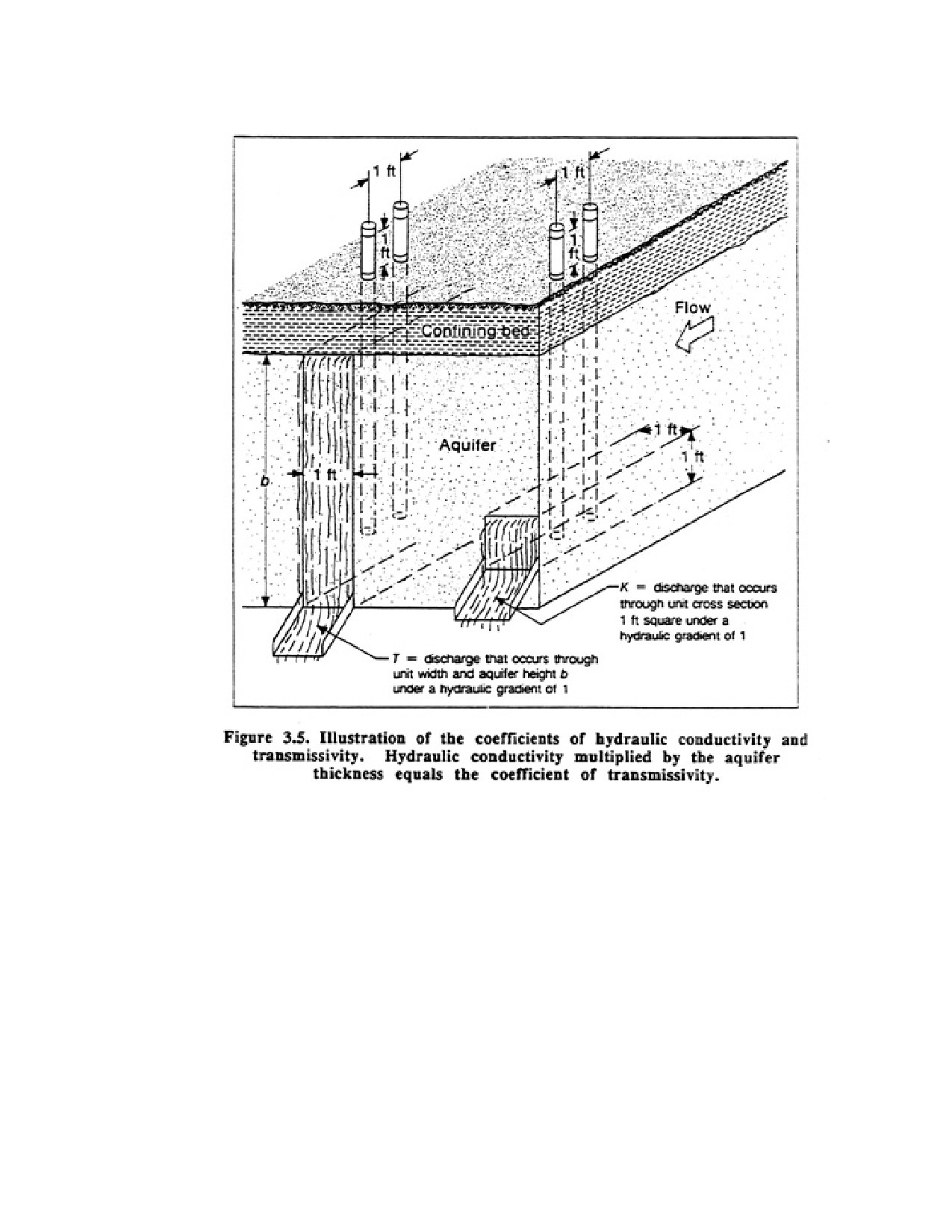
Page 35 of 360
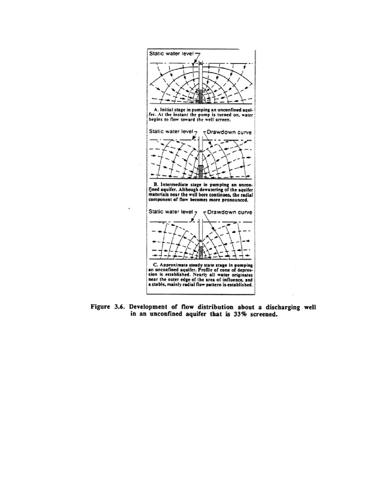
Page 36 of 360
The transmissivity and storage coefficients are especially important because they define the hydraulic
characteristics of a water-bearing formation. The coefficient of transmissivity indicates how much water
will move though the formation, and the coefficient of storage indicates how much can be removed by
pumping or draining. If these two coefficients can be determined for a particular aquifer, predictions of
great significance can usually be made. Some of these are:
1. Drawdown in the aquifer at various distances from a pumped weld.
2. Drawdown in a well at any time after pumping starts.
3. How multiple wells in a smell area will affect one another.
4. Efficiency of the intake portion of the well.
5. Drawdown in the aquifer at venous pumping rates.
3.3. Cone of Depression
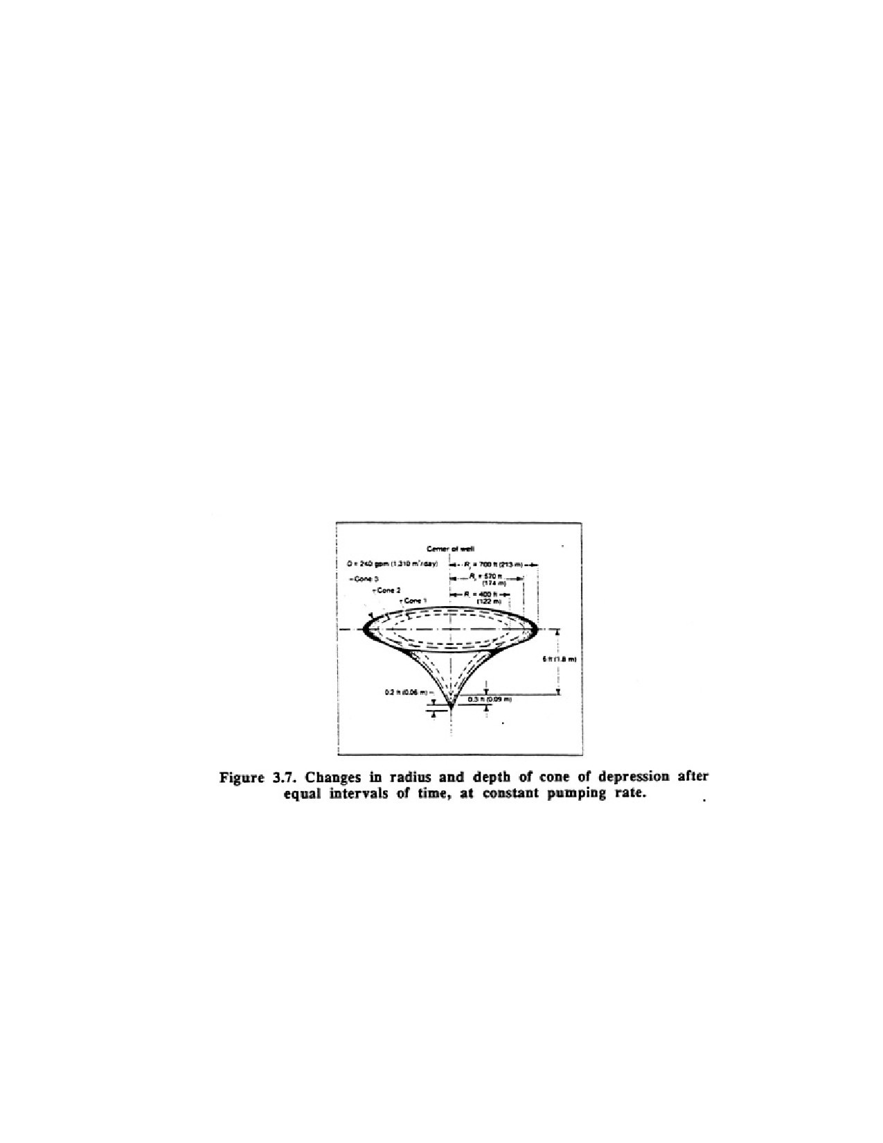
Page 37 of 360
When water is pumped from a well, the initial discharge is derived from casing storage and aquifer
storage immediately surrounding the well (Figure 3.6). As pumping continues, more water must be
derived from aquifer storage at greater distances from the well bore. This means that the cone of
depression must expand. The radius of influence of the well increases as the cone expands. Drawdown at
any point also increases as the cone deepens to provide the additional head required to move the water
from greater distances. The cone expands and deepens more slowly with time, however, because an
increasing volume of stored water is available with each additional foot of horizontal expansion.
Figure 3.7 illustrates how the cone of depression expands during equal intervals of time. Assume that
after 10 hours of pumping the radius of the cone is 400 ft and its depth is 6 ft at the well bore. At the end
of 20 hours, the cone's radius has expanded to 570 ft and its depth has increased to 6.3 ft. In the second
10 hours, the cone has only extended outward an additional 170 ft and deepened by an additional 0.3 ft.
An additional radial expansion of only 130 ft and an increase in depth of only 0.2 ft occurs in the next 10
hours. Calculations of the volume of each of the cones would show that cone 2 has twice the volume of
cone 1, and cone 3 has three times the volume of cone 1. This occurs because, at a constant pumping
rate, the same volume of water is discharged from the well during each 10-hour interval Thus, the
increase in volume of the cone of depression is constant over time if the well is being pumped at a
constant rate and the aquifer is homogeneous.
It is evident from this example that after some hours deepening or expansion of the cone during short
intervals of pumping is barely discernible. This often leads observers to conclude that the cone has
stabilized and will not expand or deepen as pumping continues. The cone of depression will continue to
enlarge, however, until one or more of the following conditions is met:
1. It intercepts enough of the flow in the aquifer to equal the pumping rate.
2. It intercepts a body of surface water from which enough additional water will enter the aquifer to
equal the pumping rate when combined with all the flow toward the well.
3. Enough vertical recharge from precipitation occurs within the radius of influence to equal the pumping
rate.
Page 38 of 360
4. Sufficient leakage occurs through overlying or underlying formations to equal the pumping rate.
When the cone has stopped expanding because of one or more of the above conditions, equilibrium
exists. There is no further drawdown with continued pumping In some wells, equilibrium occurs within a
few hours after pumping begins; in others, it never occurs even though the pumping period may be
extended for years.
CHAPTER 4
WELL DRILLING METHODS
Various well drilling methods have developed because geologic conditions range from hard rock such as
granite and dolomite to completely unconsolidated sediments such as alluvial sand and gravel. Particular
drilling methods have become dominant in certain areas because they are most effective in penetrating
the local aquifers and thus offer cost advantages. In many cases, however, the drilling contractor may
vary the usual drilling procedure depending on the depth and diameter of the well, type of formation to
be penetrated, sanitation requirements, and principal use of the well. It is obvious, then, that no single
drilling method is best for all geologic conditions and well installations. In most cases, the drilling
contractor is best qualified to select the particular drilling procedure for a given set of construction
parameters. Successful drilling is both an art developed from long experience and the application of good
engineering practices.
Well construction usually comprises four or five distinct operations: drilling, installing the casing,
placing a well screen and filter pack, grouting to provide sanitary protection, and developing the well.
Two or more of these operations may be carried out simultaneously, depending on the drilling method
used. For example, when drilling into an unconsolidated formation by the cable tool or drill through
casing driver methods, the casing is installed as drilling proceeds. When a well point (screen) is driven,
three operations are performed simultaneously: the borehole is opened, the casing installed, and the well
screen set.
Well drilling and installation methods are so numerous that only the basic principles and some of their
applications can be described in this chapter. The practical limits of major drilling methods are presented
for various geologic conditions.
4.1. CABLE TOOL METHOD
Developed by the Chinese, the cable tool percussion method was the earliest drilling method and has
been in continuous use for about 4,000 years. Using tools constructed of bamboo, the early Chinese
could drill wells to a depth of 3,000 ft, although construction sometimes took two to three generations.
Cable tool drilling machines, also called percussion or "spudder" rigs, operate by repeatedly lifting and
dropping a heavy string of drilling tools into the borehole. The drill bit breaks or crushes consolidated
rock into small fragments, whereas the bit primarily loosens the material when drilling in unconsolidated
formations. In both instances, the reciprocating action of the tools mixes the crushed or loosened
particles with water to form a slurry or sludge at the bottom of the borehole. If little or no water is
present in the penetrated formation, water is added to form a slurry. Slurry accumulation increases as
drilling proceeds and eventually it reduces the impact of the tools. When the penetration rate becomes
unacceptable, slurry is removed at intervals from the borehole by a sand pump or bailer.
Page 39 of 360
A full string of cable tool drilling equipment consists of five components: drill bit, drill stem, drilling
jars, swivel socket, and cable. Each component has an important function in the drilling process. The
cable tool bit is usually massive and heavy so as to crush and mix all types of earth materials. The drill
stem gives additional weight to the bit, and its length helps to maintain a straight hole when drilling in
hard rock. (Please scroll to next page for graphic)
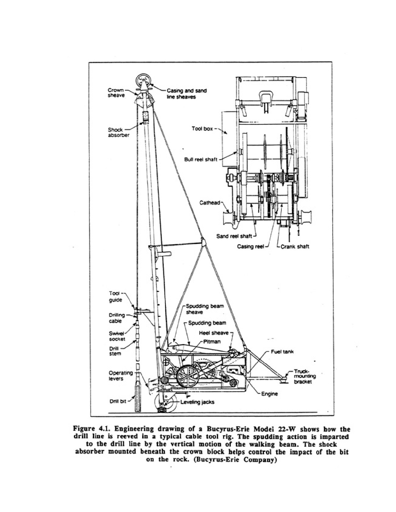
Page 40 of 360
Page 41 of 360
Drilling jars consist of a pair of linked, heat-treated steel bars. When the bit is stuck, it can be freed most
of the time by upward blows of the free-sliding jars. This is the primary function of the drilling jars;
except in unusual circumstances, they serve no purpose in the drilling operation itself. The stroke of the
drilling jars is 9 to 18 in and distinguishes them from fishing jars which have a stroke of 18 to 36 in or
longer.
The swivel socket connects the stung of tools to the cable; in addition, the weight of the socket supplies
part of the weight of the drill tools. It also supplies part of the upward energy to the jars when their use
becomes necessary. The socket transmits the rotation of the cable to the tool string and bit so that new
rock is cut on each downstroke, thereby assuring that a round, straight hole will be cut. The elements of
the tool string are screwed together with right-hand threaded tool joints of standard API (American
Petroleum Institute) design and dimension.
The wire cable that carries and rotates the drilling tool is called the drill line. It is a 5/8-to 1 in left-hand
lay cable that twists the tool joint on each upstroke to prevent it from unscrewing. The drill line is reeved
over a crown sheave at the top of the mast, down to the spudding sheave on the walking beam, to the
heel sheave, and then to the working-line side of the bull reel (Figure 4.1). Bull reels are generally set up
with a separator on the drum to provide a working-line side and a storage-line side.
Bailers used to remove the mud or rock slurry consist of a pipe with a check valve at the bottom. The
valve may be either a flat pattern or a ball-and-tongue pattern called a dart valve. A bail handle at the top
of this tool attaches to a cable called the sand line. The sand line is threaded over a separate sheave at the
top of the mast and down to the sand-line reel. The diameter of the sand line can vary according to the
anticipated loads.
Another type of bailer is called the sand pump or suction bailer. This bailer is fitted with a plunger so
that an upward pull on the plunger tends to produce a vacuum that opens the valve and sucks sand or
slurried cuttings into the tubing. The sand pump can have a bit bottom, but more often in water well
drilling it has a flat bottom with a flap-type valve. Some sand pump bailers have a latch bottom for slurry
release. Most sand pumps are either 10 or 20 ft long.
The characteristic up and down drilling action of a cable-tool machine is imparted to the drill line and
dolling tools by the walking beam. The walking beam pivots at one end while its outer end, which carries
a sheave for the drill line, is moved up and down by a single or double pitman connected to a crank shaft.
The vertical stroke of the walking beam, and thus the drill tools, can be varied by adjusting the position
of the pitman pin on the bull gear and the pitman connection to the walking beam. The number of strokes
per minute can be varied by changing the speed of the drive shaft. The bull gear is driven by a pinion
mounted on a clutch. This clutch, the friction drive for the sand line (on smaller cable tool rigs only), and
the drive pinion for the drill-line reel are all mounted on the same drive shaft assembly.
Another drum, called a casing reel, is frequently added to the basic machine assembly. The casing reel is
capable of exerting a powerful pull on a third cable, the casing line. This cable is used for handling pipe,
tools, and pumps, or other heavy hoisting. It may be used to pull a string of casing when the cable is
reeved with blocks to make two-, three-, or four-part lines.
Another commonly used auxiliary hoisting device on a cable tool machine is called a cathead. Use of this
drum requires that a heavy line of manila rope be carried on a separate sheave at the top of the derrick.
This line may be used for handling light loads and alternately lifting and dropping tools such as a drive
block or bumper which are used to drive or lift casing.
Page 42 of 360
Every cable tool machine has certain interdependent limits on borehole depth and diameter. If a hole is
relatively small in diameter, it may be drilled to relatively great depth. In large diameter holes, the
weight of the drill string and cable may become so excessive that the machine cannot function.
Collapsing formations may further limit the effective depth for large-diameter casing, because
considerable friction develops between the casing and borehole wall while the casing is being driven. In
many cases, the casing size is progressively decreased as the hole is deepened, thereby reducing friction
and also the weight of the drilling tools. Friction between the borehole wall and casing can be reduced by
the addition of a drilling fluid slurry abound the outside of the casing during driving. This small amount
of slurry will also decrease the energy required for pulling back casing to expose screens set within the
casing. In water well drilling, the depth capability for cable tool rigs ranges from 300 to 5,000 ft.
The drilling motion of the cable tool machine must be synchronized with the gravity fall of the tools for
effective penetration. Several factors (thickness of the slurry in the borehole, whip in the cable, hole
alignment, and rocks protruding in the borehole) may interfere with the free gravity fall, and the driller
must adjust the motion and speed of the machine to the vertical movement of the tools. Effective drilling
action is obtained when the engine speed is synchronized with the fall of the tools and the stretch of the
cable, while paying out the correct amount of cable to maintain proper feed of the bit. The bit should
strike the bottom of the hole at the extreme (elastic) limit of the cable and immediately snap upward so
that a sharp blow is given to the earth material by the bit. This requires some resilience and elasticity in
the cable and certain parts of the rig mechanism. An elastic snubber or shock absorber is usually installed
in the mounting of the drill-line crown sheave to provide part of the resilience in the system. The shock
absorber compresses as the walking beam completes its upstroke and starts its pull on the cable. Cable
tension then reaches its maximum, because the tools are still moving downward. The shock absorbers
rebound helps to lift the tools sharply after they strike bottom. The objective is to give the tools that
peculiar whip at the end of the stroke which is essential to rapid drilling. At the surface, the cable will
appear to be constantly in tension. When properly done, this technique conserves power and increases
drilling speed. The shock absorber also dampens the vibration that occurs when the drill bit strikes the
bottom of the hole; it protects the derrick and the rest of the machine from severe shock stresses.
The cable tool method has survived for thousands of years because it is reliable for a wide variety of
geologic conditions. It may be the best, and in some cases the only, method to use in coarse glacial till,
boulder deposits, or rock strata that are highly disturbed, broken, fissured, or cavernous. In situations
where the aquifers are thin and yields are low, the cable tool operation permits identification of zones
that might be overlooked in other drilling methods. The cable tool method offers the following
advantages:
1. Rigs are relatively inexpensive.
2. Rigs are simple in design and require little sophisticated maintenance.
3. Machines have low energy requirements.
4. Borehole is stabilized during the entire drilling operation.
5. Recovery of samples is possible from every depth unless heaving conditions occur.
6. Wells can be drilled in areas where little make-up water exists.
7. Wells can be constructed with little chance of contamination.
8. The driller maintains intimate contact with the drilling process and the materials encountered by
keeping a hand on the drilling cable.
9. Because of size, machines can be operated in more rugged, inaccessible terrain or in other areas where
space is limited.
10. Rigs can be operated in all temperature regimes.
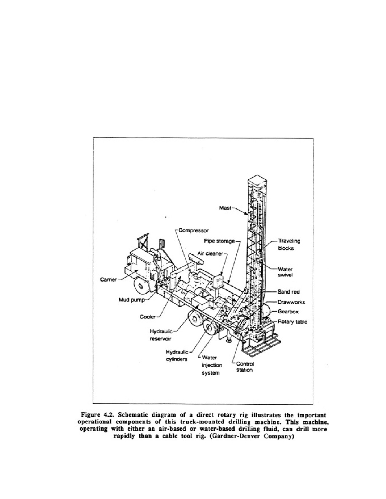
Page 43 of 360
11. Wells can be drilled in formations where lost circulation is a problem.
12. Wells can be bailed at any time to determine the approximate yield at that depth.
Some disadvantages of the cable tool method include the following:
1. Penetration rates are relatively slow.
2. Casing costs are usually higher because heavier wall or larger diameter casing may be required.
3. It may be difficult to pull back long strings of casing in some geologic conditions, unless special
equipment is available.
4.2 DIRECT ROTARY DRILLING
Page 44 of 360
The direct rotary drilling method was developed to increase drilling speeds and to reach greater depths in
most formations. The borehole is drilled by rotating a bit, and cuttings are removed by continuous
circulation of a drilling fluid as the bit penetrates the formation. The bit is attached to the lower end of a
string of drill pipe, which transmits the rotating action from the rig to the bit. In the direct rotary system,
drilling fluid is pumped down through the drill pipe and out through the ports or jets in the bit, the fluid
then flows upward in the annular space between the hole and drill pipe, carrying the cuttings in
suspension to the surface. At the surface, the fluid is channeled into a settling pit or pits where most of
the cuttings drop out. Clean fluid is then picked up by the pump at the far end of the pit or from the
second pit and is recirculated down the hole. For relatively shallow wells, 150- to 500-gal portable pits
may be used; much larger portable pits, 10,000 to 12,000 gal, are used for deeper wells. Mud pits may
also be excavated for temporary use during drilling and then backfilled after completion of the well.
Before 1920, the type of rotary drill used in water well drilling was commonly called a whirler. This
equipment used the well casing itself as the drill pipe. The lower end of the pipe was fitted with a
serrated cutting shoe with an outside diameter a little larger than the drill pipe couplings. The sawteeth of
the shoe cut and loosened the materials as the pipe was rotated. Water was pumped under pressure
through the pipe to lift the cuttings to the surface. Native clays and silt were depended upon to seal the
borehole wall to maintain circulation; prepared drilling fluids were not used The method was suitable for
drilling only relatively small-diameter, shallow wells in unconsolidated formations that did not contain
cobbles or boulders.
In the 1930's, shot-hole rotary drills, used for seismograph work in oil exploration, were successfully
adapted for drilling smog diameter water wells. Shot-hole machines, however, could not drill the large
diameter holes necessary for water well work because the mud pump and drill pipe were generally too
small to circulate enough drilling fluid to efficiently drill even an 8-in well. In time, truck-mounted
portable rigs for drilling large diameter water wells were developed from oil field exploration
technology.
The components of the rotary drilling machine are designed to serve two functions simultaneously:
operation of the bit and continuous circulation of the drilling fluid. Both are indispensable in cutting and
maintaining the borehole. For economic and efficient operation, rotary drillers must acquire considerable
knowledge concerning these factors and how they relate to various formation conditions.
In direct circulation rotary drilling for water wells, two general types of bits are used—the drag bit
(fishtail, three, and six-way designs) and the roller cone bit, usually called a rock bit. Drag bits have
short blades, each forged to a cutting edge and faced with durable metal. Short nozzles direct jets of
drilling fluid down the faces of the blades to clean and cool them. Drag bits have a shearing action and
cut rapidly in sands, clays, and some soft rock formations, but they do not work well in coarse gravel or
hard-rock formations.
Roller (cone) bits exert a crushing and chipping action, making it possible to cut hard formations. The
rollers, or cutters, are made with either hardened steel teeth or tungsten carbide inserts of varied shape,
length, and spacing, designed so that each tooth applies pressure at a different point on the bottom of the
hole as the cones rotate. The teeth of adjacent cones intermesh so that self-cleaning occurs. Long,
widely spaced teeth are used in bits designed to cut soft clay formations, whereas shorter, closer spaced
teeth are used for denser formations. Some roller bits are made with carbide buttons for particularly
dense and abrasive formations such as dolomite, granite, chert, basalt, and quartzite.
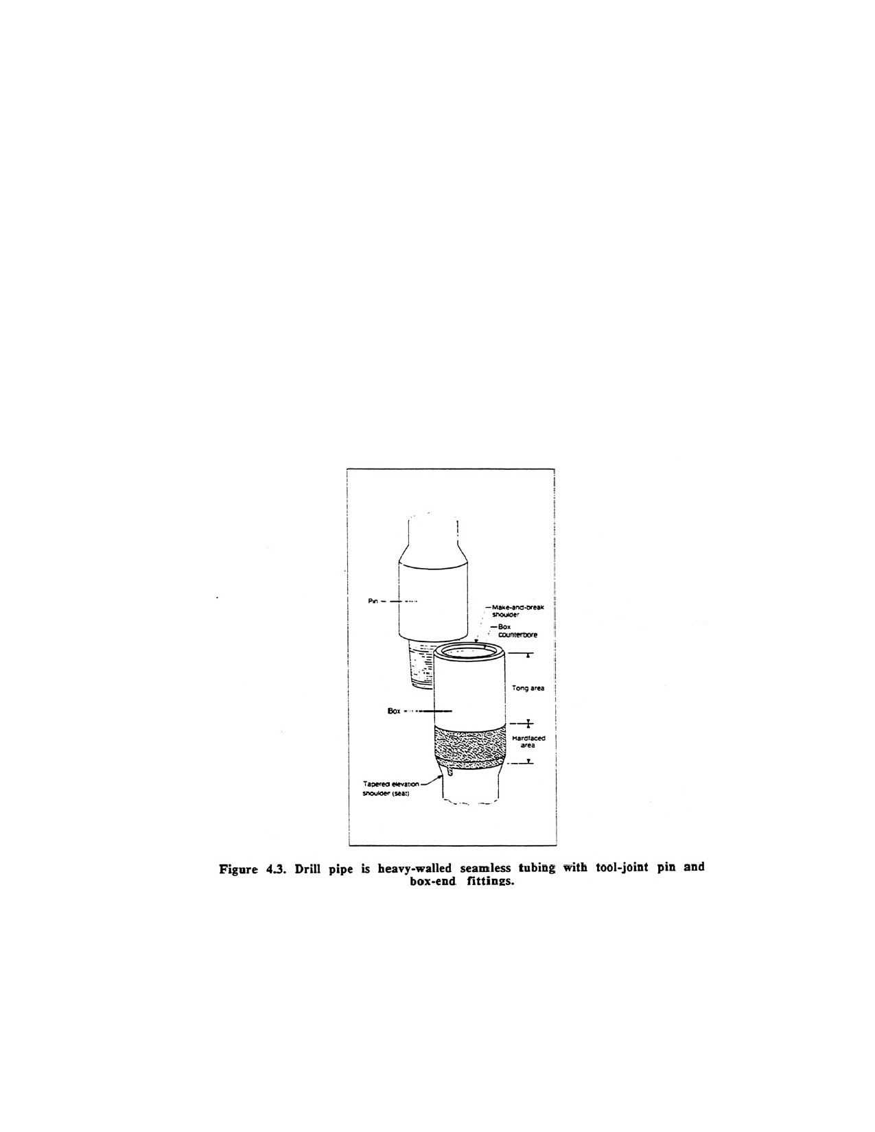
Page 45 of 360
The tricone bit, used as an all-purpose bit in every type of formation, has conically shaped rollers on
spindles and bearings set at an angle to the axis of the bit. Another design has four rollers; two are set at
an angle and two are nonnal to the vertical axis of the bit. The cutting surfaces of all roller bits are
flushed by jets of drilling fluid directed from the inside (center) of the bit. The jets can be sized so as to
maximize the cutting action of the bit. The jets are also effective in breaking up or washing away soft
formation materials.
The bit is attached to the lower end of the drill pipe, which resembles a long tubular shaft. The drill
string usually consists of four parts: the bit, one or more drill collars or stabilizers, one or more lengths
of drill pipe, and, in table-drive machines, the kelly. Selection of the bottornhole assembly will depend
on the physical conditions of the geologic materials. These include dip of the formation, presence of
faults or fractures, and drillability of the formation.
Each drill collar is a heavy-walled length of drill pipe; one or more drill collars are used to add weight to
the lower put of the drill-stem assembly. The concentration of weight just above the bit helps to keep the
hole straight, and provides sufficient weight for the bit to maintain the proper penetration rate. Drill
collars fitted with stabilizer bars or rollers are even more effective in drilling straight boreholes.
Stabilizers are an important component of the bottom-hole tools. To be effective in maintaining straight
holes in soft formations, the stabilizer must have large wall contact. Increased contact can be achieved by
using stabilizers with longer and wider blades, or by using longer stabilizers. The flow of drilling fluid
upward around the stabilizer must not be restricted too much, however, because cuttings may pack
around die stabilizer. This leads to sticking and a possible loss of circulation if back pressure builds up.
Weakening of the formation structure can also result from the pressme increase. Accumulation of
Page 46 of 360
cuttings around the stabilizer may also cause local zones of erosion in the borehole wall. In relatively
hard formations, the stabilizer can perform satisfactorily with less wall contact.
Drill pipe is seamless tubing manufactured in joints that are usually 5.0 to 20.0 ft long, although other
lengths are available. Each joint is equipped with a tool joint pin on one end and a tooljoint box on the
other (Figure 4.3). Outside diameters of drill pipe used for direct rotary drilling generally range from 2 to
6 in. High circulation rates for drilling fluids in water well drilling require that the drill pipe diameter be
adequate to hold friction loss in the pipe to an acceptable level so as to reduce the power required for the
pump. For efficient operation, the outside diameter of the tool joint should be about two-thirds the
borehole diameter; this ratio may be impractical, however, for holes larger than 10 in.
In table-drive machines, the kelly constitutes the uppermost section of the drill string column. It passes
through and engages in the opening in the rotary table, which is driven by hydraulic or mechanical
means. The outer shape of the kelly may be square or hexagonal, or round with lengthwise grooves or
flutes cut into the outside wall. Made about 3 ft longer than one joint of drill pipe, the kelly has an inside
bore that is usually smaller than that of the drill pipe because of the heavy wall thickness required. The
square, hexagonal, or grooved circular section of the kelly works up and down through drive bushings in
the rotary table. With the bushings properly in place around the kelly, the entire drill stem and bit are
forced to turn with the rotary table. While rotating, the kelly slips down through the drive bushings to
feed the bit downward as the hole is drilled. The upper end of the kelly connects to a swivel (by a left-
hand threaded joint) that is suspended from a traveling block in the derrick. A heavy thrust bearing
between the two parts of the swivel carries the entire weight of the drill string while allowing the drill
pipe to rotate freely.
Some rotary drilling machines use a towhead drive to rotate the drill string. In this system, the rotational
unit moves up and down the mast; energy is obtained from a hydraulic transmission unit powered by a
motor-driven pump.
In both the rotary table and top-head drive mechanisms, the driller can determine the rotation speed
depending on the resistance of the formation and the rate of penetration. For shallow boreholes of 200 to
400 ft. pull-down pressure may be applied to the bit. Down-hole pressures on the bit can be increased
beyond the weight of the drill string by exerting a pull-down force derived from the weight of the drilling
rig. The chain assemblies (or cables) on the mast are used to transfer part of the weight of the drilling rig
to the drill string. Caution should be used to avoid excessive pull-down pressure (weight) because hole
deflection (crooked holes) may result. Rotation speed is adjusted to the pull-down or existing pressures
on the bit. In general the higher the pressure on the bit the slower the rotation should be.
Adding drill rods to the drill string or removing rods to change bits or take split-spoon or core samples is
a major part of every rotary drilling operation. “Tripping in" and "tripping out" are the terms used to
describe the process of running the bit into or pulling the bit from the hole. Most newer drilling rigs have
been designed to make this process as fast and automated as possible. With some new machines, it is
possible to pull back a 20-ft rod and remove it from the drill string in approximately 30 seconds. In
general, top-head drive machines, especially those equipped with carousels (drill rod storage racks
mounted on the mast), offer an advantage in rod handling speed, although recent modifications in table-
drive machines have enabled this type of rig to match the speed of the top-head drive rotaries.
In top-head drive machines, no kelly is required and therefore the bottom sub of the hydraulic drive
motor is connected directly to the drill rod. Additional rods can be taken directly from a carousel by the
top-head drive unit. If the machine is equipped with side storage racks, a sand line must be used to raise
Page 47 of 360
the drill rod into position.
Internal pressure created by tile drilling fluid can cause a momentary but forceful surge of drilling fluid
out of the drill string at the point where the kelly is disconnected from the upper drill rod.
Drillers usually break this joint slowly to allow the pressure to dissipate so that drilling fluid is not
expelled violently. Occasionally during the addition of a drill mud, drilling fluid may continue to
overflow from the top of the rods. Confining pressures within permeable material in the borehole may be
causing this flow, but it is more likely that clay "collars" packed around the drill rods are falling deeper
into the borehole, thereby pushing drilling fluid back up the center of the rods.
When circulation of the drilling fluid is interrupted for some reason, to add drill pipe for example, the
cuttings being canted by the mud column tend to drop back toward the bottom of the hole. Cuttings can
bridge on tool joints and build up on top of the bit if they settle rapidly. Excessive pump pressures may
then be required to move these cuttings and resume circulation: if the cuttings cannot be removed, the
drill pipe and bit become stuck in the hole (sanded in). Many drilling fluids develop gel strength, that is,
the ability to suspend cuttings when flow slows or stops. It may be advisable before adding drill pipe to
circulate the fluid for a few minutes without applying bit pressure to clear the hole of most cuttings. This
is particularly important for deep holes.
The drilling fluid prevents caving of the borehole because it exerts pressure against the wall. As long as
the hydrostatic pressure of the fluid exceeds the earth pressures and any confining pressure in the
aquifer, the hole will remain open. The pressure at any depth is equal to the weight of the drilling fluid
column above that point.
If caving occurs while drilling, weighting material may be added to increase the drilling fluid weight or
special additives may be added to isolate any swelling clays. To prevent excessive intrusion of fine
drilling fluid particles into the formation, the drilling fluid weight should be just heavy enough to
maintain hole stability. Numerous additives are available for imparting specific properties to drilling
fluids. Chapter 5 discusses the various kinds of drilling fluids, with particular reference to their
advantages and disadvantages in certain geologic formations.
As drilling progresses, a film of small particles builds up on the wall of the borehole. This flexible lining,
which may consist of clay, silt, or colloids, forms when the pressure of the drilling fluid forces smog
volumes of water into the formation, leaving the fine, suspended material on the borehole wall In time,
the lining completely covers the wall and holds loose particles or crumbly materials in place. It protects
the wall from being eroded by the upward-flowing stream of drilling fluid, and acts to seal the wall and
reduce the loss of fluids into surrounding permeable formations. Although the flexible lining effectively
controls fluid losses in the borehole, it cannot prevent the hole from collapsing if the hydrostatic pressure
created by the drilling fluid is not greater than the pressure exerted by the water in the formation.
The drip bit is cooled and cleaned by the jets of fluid that are directed at relatively high velocity over the
cutting faces and body section of the bit. A properly prepared drilling fluid is an excellent lubricant, but
the viscosity must be controlled so that the concentration of cuttings does not become excessive.
In direct rotary drilling, water and special viscosity-building additives are usually mixed to produce a
drilling fluid. Drilling fluids can be mixed in either a portable pit canted from site to site or in a pit
excavated next to the drilling rig. Cuttings collecting on the bottom of the pit must be removed
periodically to maintain the efficiency of the pit. When enough drilling fluid has been mixed and
Page 48 of 360
sufficient time has elapsed to insure complete hydration, it is cad into the hole using a mud pump. The
size of the mud pump must be chosen carefully so that the correct uphole velocity can be maintained.
In clay-rich formations, the driller may begin drilling with clean water which quickly mixes with the
natural clays in the borehole to form a thin clay slurry. This drilling fluid is used in the upper potion of
the borehole, commonly the first 100 to 300 ft. Thereafter, most drillers will mix fluids with additives of
either high-quality clays or natural or synthetic polymers so that proper viscosity and hydrostatic
pressure can be maintained in the borehole.
Direct rotary drilling, the most common method, offers the following advantages:
1. Penetration is relatively high in all types of materials.
2. Minimal casing is required during the drilling operation.
3. Rig mobilization and demobilization are rapid.
4. Well screens can be set easily as part of the casing installation.
Major disadvantages include the following:
1. Drilling rigs are costly.
2. Drilling rigs require a high level of maintenance.
3. Mobility of the rigs may be limited depending on the slope and condition (wetness) of the land
surface.
4. Collection of accurate samples requires special procedures.
5. Use of drilling fluids may cause plugging of certain formations.
6. Rigs cannot be operated economically in extremely cold temperatures.
7. Drilling fluid management requires additional knowledge and eminence.
4.3. REVERSE CIRCULATION ROTARY DRILLING
In direct rotary drilling, the viscosity and uphole velocity of the drilling fluid are the controlling factors
in removing cuttings effectively. Unless cuttings can be removed, drilling cannot continue. Because of
limitations in pump capacity and therefore effective cuttings removal most direct rotary machines used to
drill water wells are limited to boreholes with a minimum diameter of 22 to 24 in. This size may not be
sufficient for high capacity wells, especially those that are to be filter packed. Also, as hole diameters
increase past 24 in, the rate of penetration by direct rotary machines becomes less satisfactory. To
overcome the limitation on hole diameter and drilling rate, reverse circulation machines were designed,
originally they were used only in unconsolidated formations. Recently, reverse circulation drilling has
been used in soft consolidated rocks such as sandstone and even in hard rocks using both water and air as
the drilling fluid.
The design of a reverse circulation rig is essentially the same as that of the direct rotary rig except most
pieces of equipment are larger. For example, larger compressors and mud pumps are required because of
the larger diameter boreholes. Only table drives are used in reverse circulation drilling because of the
large borehole diameter and the torque required to turn the bit.
In reverse circulation rotary drilling, flow of the drilling fluid is reversed when compared with the direct
rotary method. The suction end of the centrifugal pump, rather than the discharge end is connected
through the swivel to the kelly and drill pipe. The drilling fluid and its load of cuttings move upward
inside the drill pipe and are discharged by the pump into the setding pit (Figure 4.4). Centrifugal pumps
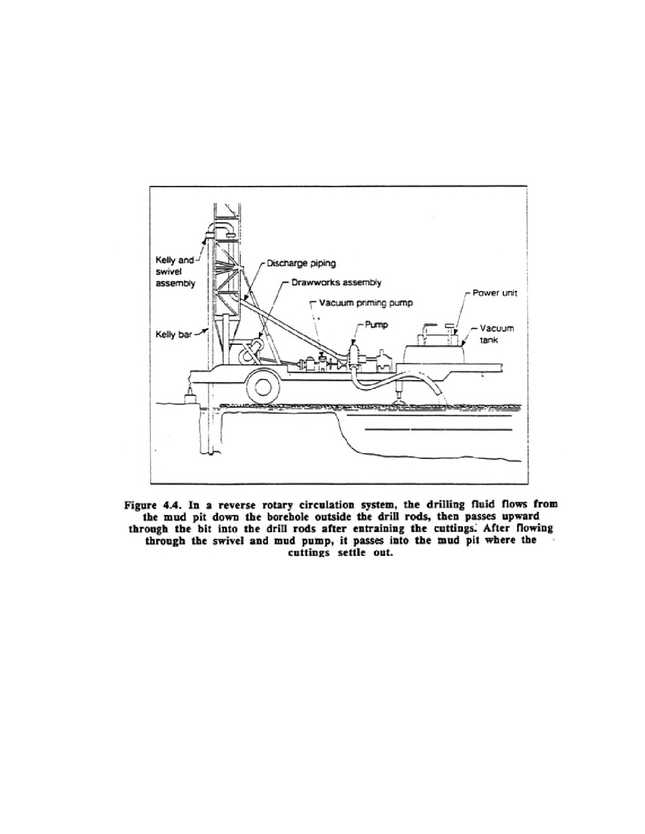
Page 49 of 360
with large passageways are often used to pump the drilling fluid because they can handle cuttings
without excessive wear on the pump. In operation, however, most of the cuttings do not actually enter
the pump but bypass it by means of an eductor system. An uphole velocity of at least 150 ft/min is
recommended. The fluid returns to the borehole by gravity flow. It moves down the annular space
between the drill pipe and borehole wall to the bottom of the hole, picks up the cuttings, and reenters the
drill pipe through ports in the drill bit.
In the reverse circuladon romy method, die drilling fluid can best be described as muddy water rather
than drilling fluid; drilling fluid additives are seldom mixed with the water to make a viscous fluid
Suspended clay and silt that recirculate with the fluid are mostly fine materials picked up from the
formations as drilling proceeds. Occasionally, low concentrations of a polymeric drilling fluid additive
are used to reduce friction, swelling of water-sensitive clays, and water loss.
To prevent caving of the hole, the fluid level must be kept at ground level at all times, even when drilling
is suspended temporarily, to prevent a loss of hydrostatic pressure in the borehole. The hydrostatic
pressure of the water column plus the velocity head (inertia of the water moving downward) outside the
drill pipe support the borehole wall. Erosion of the wall is usually not a problem because velocity in the
annular space is low.
4.3.1. During Drilling
Water infiltrates the permeable formations surrounding the borehole. Some of the fine particles
Page 50 of 360
suspended in the fluid are filtered out on the wall of the hole, resulting in a thin mud deposit that
partially clogs the pores and reduces the water loss. A considerable quantity of made-up water is usually
required and must be immediately available at all times when drilling in permeable sand and gravel.
Under these conditions, water loss can increase suddenly, and if this causes the fluid level in the hole to
drop significantly below the ground surface, caving usually results. Water loss can be reduced by nixing
clay additives with the fluid, but this is usually avoided unless absolutely necessary. As little as 20 gpm
of make-up water is enough in some cases, whereas as much as 1,000 gpm may be needed when drilling
through a highly permeable aquifer such as coarse, dry gravel.
The settling pit and water supply pit should hold at least three times the volume of the material to be
removed during the drilling operation. The circulation rate for the water used in drilling is commonly
500 gpm or more.
Many reverse rotary drilling rigs are equipped with air compressors to aid in circulating the drilling fluid.
When drilling has reached a depth sufficient for proper operation of an air lift within the drill pipe, the
mud pump is bypassed. Compressed air is introduced through a 1-1/4 or 1-1/2 plastic or metal air line
suspended inside the drill pipe, or through an external air line attached to the outside of the drill pipe.
The external air line system may consist of two pipes welded on opposite sides of the drill pipe. The air
is injected by means of a manifold into the drill string at the proper depth. In these processes, water is
lifted to the surface from the borehole.
Any cobbles or boulders larger than the drill pipe or the openings in the drill bit cannot be brought out in
the drilling operation, because most reverse rotary bits cannot break cobbles. Thus, further penetration is
impossible when a few large cobbles or boulders collect in the bottom of the hole. If the boulders are
relatively stable in the hole, a roller cone bit can be used to grind them into small fragments: cement may
be used to stabilize the boulders prior to grinding.
Most new drill pipe used in reverse circulation rotary drilling is threaded and coupled pipe that can be as
much as 8 inches in diameter and operated at depths of 2,000 ft or more.
Reverse circulation drilling is most successful in soft sedimentary rocks and unconsolidated sand and
gravel where the static water level is 10 ft or more below ground level. In cases of high static water level,
ramps are built above glade to support the drilling rig, or the weight of the drilling fluid is increased to
obtain the necessary hydrostatic pressure. The reverse circulation drilling method may not be satisfactory
when the static water level is too high and adequate water supplies are not available.
Advantages of the reverse circulation method include the following:
1. The porosity and permeability of the formation near the bore hole is relatively undisturbed compared
to other methods.
2. Large diameter holes can be drilled quickly and economically.
3. No casing is required during the drilling operation.
4. Well screens can be set easily as part of the casing installation.
5. Most geologic formations can be drilled, with the exception of igneous and metamorphic rocks.
6. Little opportunity exists for washouts in the borehole because of the low velocity of the drilling fluid.
Disadvantages include the following:
1. Large water supply is generally needed.
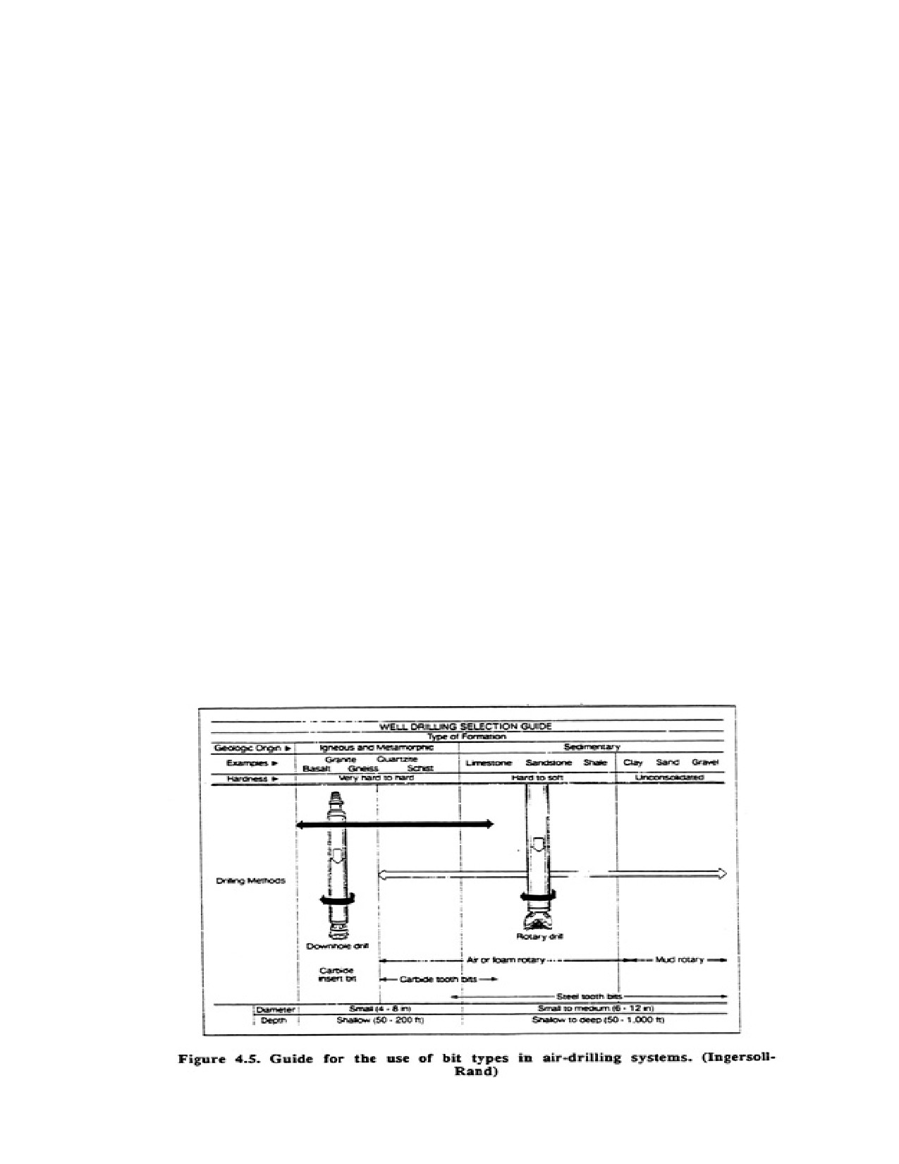
Page 51 of 360
2. Reverse rotary rigs and components are usually larger and thus more expensive.
3. Large mud pits are required.
4. Some drill sites are inaccessible because of the rig size.
5. For efficient operation more personnel are generally required than for other drilling methods.
4.4. AIR DRILLING SYSTEMS
Two different drilling methods use air as the primary drilling fluid—direct rotary air and down hole air
hammer. In conventional reverse circulation methods, air is used as an assist but not as e primary drilling
fluid. In the air rotary method, air alone lifts the cuttings from the borehole. A large compressor provides
air that is piped to the swivel hose connected to the top of the kelly or drill pipe. The air, forced down the
drill pipe, escapes through smut pons at the bottom of the drill bit, thereby lifting the cumags and cooling
the bit. The cuttings are blown out the top of the hole add collect at the surface around the borehole.
Injecting a small volume of water or surfactant and water (foam) into the air system controls dust and
lowers the temperature of the air so that the swivel is cooled. Air drilling can be done only in
semiconsolidated or consolidated materials. Therefore, to achieve the capability to operate in completely
unconsolidated as well as consolidated formations, air rotary drilling machines are often equipped with a
mud pump in addition to a high capacity air compressor. Conventional water based drilling fluids are
then used when drilling through the overlying, caving formations above the bedrock (or more
consolidated formations), whereas air is used once bedeck has been reached. Thus drillers are utilizing
various options of drilling technology to adjust to the different physical characteristics of the formation.
In many instances, cawing may have to be installed through the overburden to avoid caving or excessive
erosion of the borehole wall after changing to air circulation.
Cuttings are removed by grinding the material finely enough so that the uphole velocity of the air is
sufficient to lift them to the surface. The lifting capacity of the air can be enhanced by adding a small
amount of surfactant and water solution to the air. Larger cuttings can then be removed, thereby
increasing the drilling rate. Foam also reduces loss of air to the formation. Suggestions for use of various
drilling fluid additives are presented in Chapter 5.
Roller-type rock bits, similar to those designed for drilling with water-based fluids, can be used when
Page 52 of 360
drilling with air. Tricone rock bits up to about 12-in diameter are commonly used. Larger sizes are
available. Button bits, made with sintered tungsten-carbide inserts set into the perimeters of steel rollers,
are used successfully in many areas. Figure 4.5 lists the formations drilled effectively by carbide and
steel-tooth bits in rotary air drilling.
Weld tests with various sizes of bits have shown that the penetration rate is often faster and the bit life
longer when using air as compared with water-based drilling fluids. Better bottom-hole cleaning is partly
responsible for this difference in performance. If too much water comes into the hole during drilling,
however the penetration rate is no better than when drilling with water-based drilling fluids. Air also
keeps the bit bearings cool and clean and causes some oxidation of the bearings: the oxidized material
then becomes a lubricant. On the other hand, water-based drilling fluids are often abrasive and cause
wear on the bearings.
A second direct rotary method using air is called the "down-hole" drilling system. A pneumatic drill
operated at the end of the drill pipe rapidly stakes the rock while the drill pipe is slowly rotated. The
percussion effect is similar to the blows delivered by a cable tool bit. The hammer is constructed from
alloy steel with heavy tungsten-carbide inserts that provide the cutting or chipping surfaces. Tungsten-
carbide is extremely resistant to abrasion, but drill bits do become dull with continued use. The inserts
are sharpened by grinding when operating conditions indicate that the bit is not cutting properly.
Alternatively, the bits can be provided with carbide buttons that can be periodically replaced when worn.
Rotation of the bit helps to assure even penetration and, therefore, straighter holes even in extremely
abrasive or resistant rock types. The rates of penetration in several rock types are higher than those
obtained by other drilling methods or other types of tools. 6-in and 6-1/2-in hammer bits are most
commonly used, although sizes range up to 17-1/2-in. Cuttings are removed continuously by the air used
to drive the hammer. Unlike the conventional cable tool bit that is constantly striking previously broken
rock fragments, the bit (or buttons) on the air hammer always strike a clean surface. Thus, the air
hammer is highly efficient.
Compressed air must be supplied to the hemmer at a pressure of 100 to 110 psi. Some tools require as
much as 200 psi. To remove cuttings effectively, the upward velocity in the space outside the drill pipe
should be about 3,000 ft/min or more. For drilling 4-in holes, the air supply must be at least 100 cfm
(assuming a 2-7/8-in drill rod); for 6-in holes, at least 330 cfm is needed. Proper rotation speed is from
10 to 30 rpm; reduced speed is best in harder and more abrasive rock.
Advantages of using air drilling methods include the following:
1. Cuttings removal is extremely rapid.
2. Aquifer is not plugged with drilling fluids.
3. No maintenance costs for mud pumps (mud pumps are not used during air drilling).
4. Bit life is extended.
5. Drilling operations are not hampered by extremely cold weather.
6. Penetration rates are high, especially with down-hole hammers, in highly resistant rocks such as
dolomite or basalt.
7. An estimate can be made during drilling of the yield from a particular formation.
Disadvantages include the following:
1. Restricted to semiconsolidated and well-consolidated materials.
//////////////////////////////////////////