NATIONAL DRILLING ASSOCIATION DRILLER’S MANUAL (2005) - page 2
Page 53 of 360
2. Initial cost and maintenance costs of large air compressors are high.
Page 54 of 360
4.5. IN-VERSE DRILLING
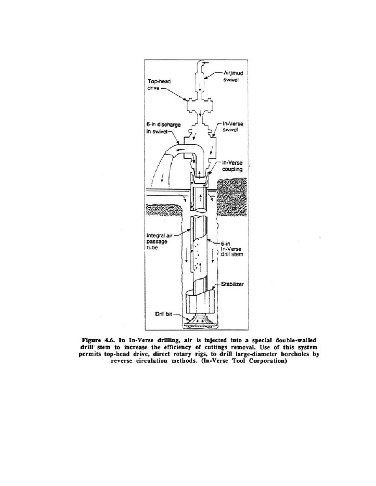
A recent innovation for the top-head drive, direct rotary machine involves the addition of an air assist by
using a special 6-in inside diameter, side discharge swivel assembly and 5-7/8 in drill pipe with built-in
air channels. This equipment permits compressed air to be injected through an injection stem into air
channels mounted outside the drill pipe and then into the drilling fluid as it moves up inside the drill pipe
(Figure 4.6). Thus, the drilling fluid and cuttings are assisted to the surface by an airlift inside the 6-in
diameter conductor (drill) pipe. This method is known as the In-Verse system and converts a direct
rotary, towhead drive machine into a reverse circulation rig. Use of the In-Verse system can increase the
capacity of a direct rotary rig to drill large-diameter wells. Depending on the rig, boreholes from 20 to 30
in can be drilled routinely. If the pulling capabilities of the rig are sufficient, enough torque is available,
and larger bits can be accommodated under the centralizer, boreholes of 30 to 60 in are possible in
Page 55 of 360
unconsolidated formations. Boreholes smaller than 12 in are not recommended because the drill pipe has
an outside diameter of approximately 9 in at the tool joint and significant erosion of the borehole wall
may occur depending on the degree of formation consolidation.
It is recommended that at least a 300 cfm compressor operating at 125 psi be used for the In-Verse
system. At this pressure, the maximum stem submergence is approximately 250 ft. If the borehole must
extend past 250 ft 50 to 60 ft of drill pipe are pulled and another injector stem is installed in the drill
string. Thus, if the drilling rig is equipped with only 250 ft of air channel pipe and the hole will be 500 ft
deep, the drill pipe with the air channels must be mounted above the conventional drill pipe for any
depth over 250 ft. This requirement increases drill pipe handling time somewhat.
The In-Verse equipped rig operates most satisfactorily with a centrifugal pump or a 3 x 4 or 5 x 6 piston
pump. The latter pump will operate at approximately 300 psi. This size pump would be required to drill
test holes or wells smaller than 12 inches in diameter using direct rotary drilling.
Advantages of the In-Verse system include the following:
1. Large-diameter boreholes can be drilled.
2. Penetration rates are high in unconsolidated sediments.
3. Less drilling fluid additives are required to lift the cuttings.
4. Development time is reduced.
Disadvantages include the following:
1. Extra costs for drip pipe, special swivel and air compressor (if the rig is not equipped with one).
2. Drill pipe handling time may increase for deep holes.
4.6 DUAL WALL REVERSE CIRCULATION ROTARY METHOD
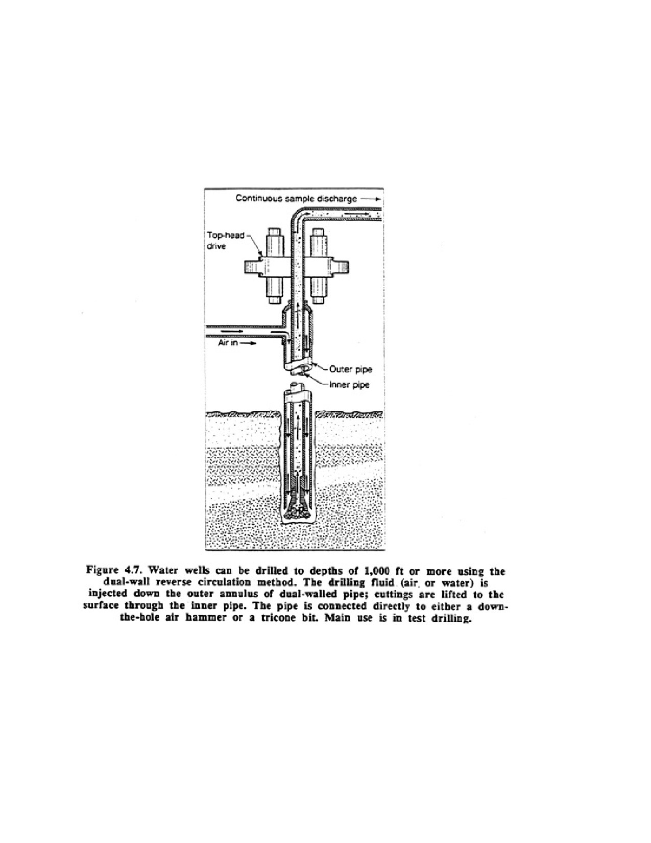
In mining exploration, a drilling system called the dual wall method has been used for many years to
obtain accurate geologic samples from known depths. The dual wall method uses flush jointed, double
wall pipe in which the drilling fluid (air or liquid) moves by reverse circulation (Figure 4.7). Unlike
conventional reverse circulation, however, the drilling fluid does not run down the outside of the drill
pipe. Instead, the flow is contained between the two walls of the dual wall pipe and only contacts the
walls of the borehole near the bit. Recently this method has been applied to water well exploration and
construction in all types of geologic formations, although its principal use is still test drilling
Available drill pipe diameters for the dual-wall method are:
3-1/2 in OD x 1-3/4 in ID
4-1/2 in OD x 2-1/2 in ID
5-1/2 in OD x 3-1/4 in ID
6-5/8 in OD x 4-1/4 in ID
9-5/8 in OD x 6-1/4 in ID
The 4-1/2 in OD size is the most common. Male and female tool joints are used to connect the outer
pipes; a connector sleeve with an "O" ring seals the joint between the inner pipes.
Page 56 of 360
Dual-wall pipe can be driven into place in loosely consolidated materials by a steam, gasoline, or diesel
operated pile hammer as the formation is being cut by a drive bit. Air or water is forced down the
annulus to lift the cuttings to the surface through the inner pipe. If bedrock is reached, drilling may be
continued by direct rotary methods using the dual-wall pipe as temporary casing. The pile driving
method is generally not used in the water well industry because the hammering compacts unconsolidated
formation materials. In addition, the method may not penetrate deeply enough for most water well
applications.
More frequently, dual-wall pipe is set by standard reverse circulation methods using a top
head-drive unit. The top-head drive should deliver about 4,500 to 5,000 ft-lb of torque to be effective.
Down-the-hole air hammers and tricone bits can be used to cut the formation. As in the pile-driving
method, air or water lifts the cuttings. Surface casing is not needed when the dual-wall system is used.
The outer pipe of the dual-wall system must be able to operate within the normal tensile, column, and
collapse pressures associated with rotary drilling. The inner pipe is under little physical stress, but the
abrasion caused by earth materials moving up the pipe from the bit causes wear. In practice this abrasion
will generally cause the inner pipe to wear out more rapidly than the outer pipe. The inner pipe can be
replaced if necessary.
Page 57 of 360
If dual-wall casing is being set by a top-head drive, several different types of bits can be used, but the bit
size is normally one nominal size larger than the drill pipe. Thus, the space between the outer pipe and
the borehole wall is small and the pipe partially (or totally) supports the wall like a conventional
stabilizer. The bit is counted into a permanent sub that has ports for passage of the drilling fluid. If a
tricone bit is used, the drilling fluid passes upward through the inner part of the bit. A bit-wear sleeve is
attached as close as possible to the cutting face and serves as a wear ring. The drilling fluid passes from
the annular space between the two pipes, through a predrilled bit sub, and is discharged toward the
cutting surface along the periphery of the bit sleeve; after entraining the cuttings, the fluid passes upward
through the inner pipe.
When a tricone bit is used, the formation sample passing upward through the inner casing originates
from a small vertical section of the formation. In the use of a down-the-hole hammer, however, the bit
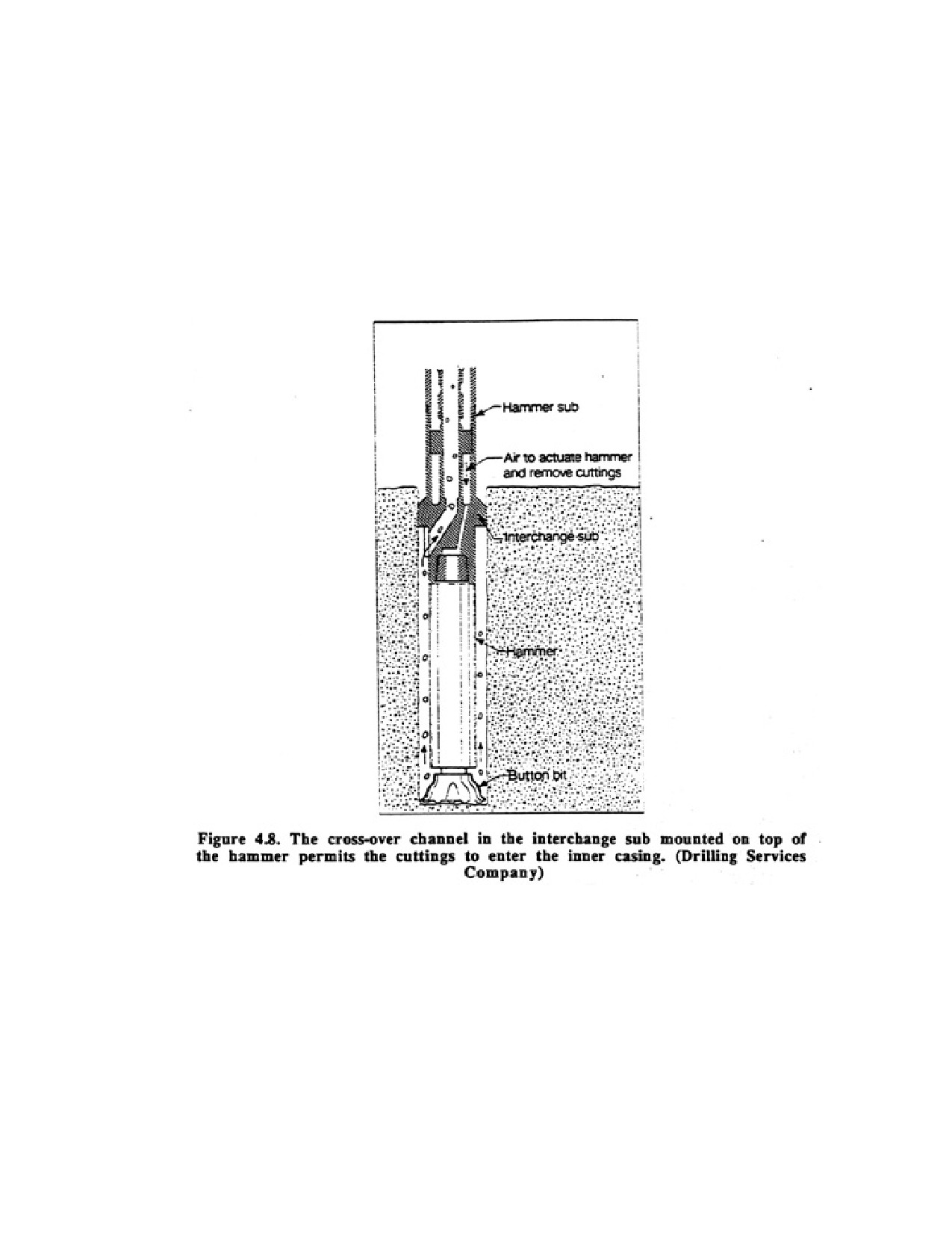
extends 4 to 5 ft out from the bottom of the dual-wall pipe. Air is forced down inside the hammer, out
the ports, and then passes up around the outside of the hammer shaft and into a special type of crossover
channel (interchange) sub and then into the inner casing (Figure 4.8). Thus, the formation sample or
water sample passing up the pipe can originate over a longer vertical section (3 to 4 ft) of the formation.
It must be remembered, however, that this distance is still small when compared with intervals sampled
by other types of rotary air drilling.
At the surface, drilling fluid enters the annular space between the inner and outer pipes by a special side
inlet swivel. Drilling fluids can consist of dry air, air and water, air and water with surfactants, or water
with clay or polymers. When air is used, velocities in the dual-wall system average 4,500 to 6,000 ft/min.
After passing down the annular space and up inside the inner pipe, air passes with the formation sample
Page 58 of 360
into a cyclone that can be equipped with an automatic splitter. The sample is collected in a sample bag.
Under ordinary drilling conditions, 5 ft of sample bag will be filled for every 20 ft of hole drilled.
In the past, most boreholes drilled using the dual-wall method rarely exceeded 500 ft. Recently,
however, depths of 800 to 1,400 It have been reached by using booster compressors.
Screens and conventional casing can be installed when using the dual-wall drilling method. Screen and
casing can be washed in over the dual pipes; small-diameter screens (1 to 2 in) can be installed through
the bit; or the dual pipe can be pulled from the hole before a screen and casing are set.
Advantages of the dual-wall system include the following:
1. Continuous representative formation and water samples can be obtained.
2. Estimates of aquifer yield can be made easily at many depths in the connation.
3. Fast penetration rates are possible in coarse alluvial deposits or broken or fissured rock.
4. Problems of lost circulation are either eliminated or reduced drastically.
5. Washout zones are reduced or eliminated.
Disadvantages of the dual-wall system include the following:
1. Initial cost of drilling rig and equipment is high.
2. System is limited to rather slim holes (less than 9 to 10 in).
3. System is limited to depths of approximately 1,200 to 1,400 ft in alluvial deposits (works best to 600
ft) and generally up to 2,000 ft in hard rocks.
4. Well-trained drilling crews are needed.
4.7. DRILL-THROUGH CASING DRIVER
Drilling rig manufacturers have long sought to build drilling machines that could combine the hole
stability of the cable tool rig and the speed of an air rotary rig. Some manufacturers are now providing
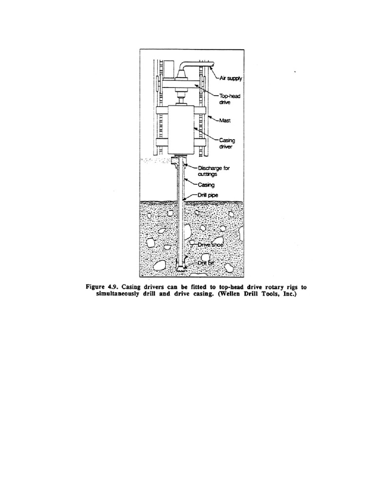
casing drivers that can be fitted to top-head drive, direct air rotary rigs (Figure 4.9). The driver can be
suspended in the most independent of the rotary drive unit because of its rather short length. Use of a
casing driver permits the casing to be advanced during drilling, but both drilling and driving can be
adjusted independently depending on the nature of the formation. Drivers are usually equipped so that
they can be used to drive upward to remove casing or expose a screen In the casing driver system, the
drill pipe and casing are usually preassembled as a unit (must be the same length, usually 20 ft) and
raised into position on the mast. The bottom of the casing is fitted with a forged or cast alloy steel drive
shoe as in cable tool operations. A bit that fits inside the casing is attached to the bottom of the drill pipe.
The top of the casing fits in the bottom of the casing driver by means of an anvil. The casing is driven by
a piston that is activated by air pressure. Table 4.1 shows this relationship between air pressure, air
consumption, and blows per minute for two sizes of drivers.
Page 59 of 360
Three drilling procedures can be followed when using the casing driver (1) the drill bit and casing
advance as a unit, (2) the casing is driven first (in unconsolidated materials only) and then the plug in the
casing is drilled out, and (3) the drill bit advances beyond the casing a few feet, is withdrawn into the
casing, and then the casing is driven.
As drilling commences using the first procedure, the cone-type bit protrudes out the bottom of the
casing, but rarely more than 12 in. Cuttings are blown up the short open hole into the casing, and pass
out the top through a horizontal tube during drilling, the casing is simultaneously driven into the ground;
that is, the casing advances at the some rate as the drill bit. The dealer adjusts the pulldown and distance
the bit is outside the casing according to the rate of advance and speed of cuttings removal. Occasionally
the bit may be pulled up within the casing for a few moments to allow the air pressure to blow out the
cuttings. Cuttings removal is facilitated by periodically adding small volumes of water if the borehole
has not encountered water. This method is particularly suitable for drilling in stratified deposits that hove
large differences in particle size, for example, sand and silt to boulders.
In the second procedure, the casing is driven into the ground approximately 0.5 to 1.5 ft and the plug in
the casing is then drilled out. The casing is usually driven only short distances so that each formation can
be identified and sampled. During the casing-driving procedure, the drill bit is withdrawn inside the
Page 60 of 360
casing and rotation is continued. Air is constantly circulated down the drill pipe to prevent clogging of
the casing.
In the third procedure, the drill bit advances out the end of the casing a few feet. When the hole begins to
become unstable, the bit is retracted into the casing and the casing is driven with the air pressure still
applied to the borehole. This method is particularly successful in semiconsolidated sands, but also
functions well in loose alluvium.
The drill-through casing driver arrangement achieves high drilling rates in most unconsolidated
formations, even in bouldery till. In fact, welding two joints of casing together often requires more time
than drilling and driving a 20-ft section of casing. When welding casing, some drillers weld straps across
the welded joint for added strength. If rock underlies an unconsolidated formation, a down-the-hole
hammer can be substituted for the cone bit once the casing is seated in the rock
Table 4.1. Relationship Between Air Pressure, Air Consumption, and Blows
per Minute for Two Sizes of Casing Drivers
Banger Model
Slammer Model
Air pressure at:
Air pressure at:
50 blows/min
40 psi
50-60 blows/min
60 psi
120 blows/min
80 psi
90-100 blows/min
90 psi
Air consumption
245 cfm
Air consumption
450 cfm
Driving Energy
2,100 ft/lb
Driving Energy
6,300 ft/lb
(Tiegre Tierra, Inc.)
If a screen is to be set, the casing can be pulled back by the top-head drive line, casing line, or, if some
simple adjustments are made, by the casing driver (the driver can be adjusted to drive upward). It is wise
to add a short piece of riser pipe to the top of the screen to prevent its loss if the casing is pulled back too
far.
For some borehole diameters, it is possible to eliminate the casing driver but still drill and install casing
at the some time. In loose overburden, an eccentric (off-centered) bit unit can be attached to a
down-the-hole hammer. In this arrangement, the bit can cut a borehole slightly larger than the casing,
allowing the casing to drop into place under its own weight. It may be necessary to drive the casing
occasionally if it does not fall into place. This can be done in shallow holes by bringing the
down-the-hole hammer out of the hole and driving on a driving cap placed on top of the casing. When
consolidated rock is reached and the casing is seated, the rotation of the drill string is reversed for one
revolution, causing the eccentric bit to center itself in the casing. It can then be withdrawn from the
borehole and a conventional bit attached to the drill pipe. The new bit will cut a hole slightly smaller
than the casing diameter.
The ability to drill and drive casing simultaneously is a major technological advance. It reduces costs and
minimizes operational difficulties for the drilling contractor, especially during extremely cold weather.
The drill-through casing method is particularly successful in bouldery tills or coarse, highly stratified
alluvial deposits where rotary methods are ineffective or cable tool methods too time consuming.
Advantages of using the drill-through casing driver include the following:
Page 61 of 360
1. Wells can be drilled in unconsolidated geologic materials that may be difficult to drill with cable tool
or direct rotary methods.
2. Unlike other rotary methods, the borehole is fully stabilized during the entire drilling operation.
3. Penetration rates are rapid even under difficult drilling conditions.
4. Lost-circulation problems are eliminated.
5. Accurate formation and water samples can be obtained.
6. Casing drivers can be used in all weather conditions.
7. No water-based drilling fluid is required in unconsolidated materials.
Disadvantages include the following:
1. Additional cost of the casing driver.
2. Noise of operation (driving casing).
When air drilling techniques are used, the driller can easily see how much water is being blown out with
the cuttings as the hole is deepened. From this observation, the driller can estimate when the borehole is
deep enough to produce the desired yield. When static water levels are low, however, the air pressure in
the hole may prevent water from entering the borehole.
The cost per foot of drilling with the air rotary system in consolidated formations is sensitive to the life
and cost of the bits as well as to penetration rates. Experience in a given locality for specific types of
consolidated rock must be depended upon for choosing the bit type that produces the best results
economically.
4.8. BORING WITH EARTH AUGERS
Earth augers of various sizes and designs are used in certain areas for drilling water wells. Three
principal types are used commonly: (1) large-diameter bucket auger, (2) solid-stem auger, and (3)
hollow-stem auger.
4.8.1. Bucket Auger
The first method utilizes a large-diameter bucket auger to excavate earth materials. This method is
referred to as rotary bucket drilling. The excavated material is collected in a cylindrical bucket that has
auger-type cutting blades on the bottom. The bucket is attached to the lower end of a kelly bar that
passes through and is rotated by a large ring gear that serves as a rotary table.
The kelly is square in cross section and consists of two or more lengths of square tubing, one length
telescoped inside the other. This design permits boning to a depth several times the collapsed length of
the kelly bar before having to add a length of drill rod between the kelly and bucket. In drilling with only
the telescoping kelly serving as the drill stem, the bucket is lifted from the hole and dumped without
disconnecting. If one or more drill rods are used for deeper boring, the drill rods must be removed each
time the bucket is brought to the surface.
Wells more than 250 ft deep have been drilled by this method, although depths of 50 to 150 ft are more
common. Water wells drilled with the bucket auger are from 18 to 48 inches in diameter, but few wells
are larger than 36 in. Special hardened teeth or tungsten carbide inserts are fixed to the cutting blades on
the bottom of the bucket when augering in dense formations.
Page 62 of 360
Rotary bucket drilling of water wells has found primary application in areas of clay formations that stand
without caving while the borehole is drilled and pipe is installed to serve as well casing. Drilling in sand
below the water table is difficult, but not impossible if the hole is kept full of water or drilling fluid. A
considerable supply of water may be needed if the sand formation is quite permeable. Thus, many
drillers will use drilling fluid additives such as bentonite or polymers to control fluid loss.
Cobbles and boulders can cause much difficulty in the bucket auger procedure because they must be
picked out of the bottom of the hole individually by using an orange-peel bucket, stone tongs, or
ram's-horn tool. The hole diameter must be large enough to permit the use of these tools when necessary.
In operation, an auger bit will remove a cylinder of material 24 to 48 in deep in a contiguous mass.
Therefore, samples obtained by the bucket auger method are representative of the formation being
drilled, unless sloughing or caving of the borehole walls has occurred.
4.8.2. Solid-Stem Auger
A second boring method uses a solid-stem auger with either a single flight (one section) or continuous
flighting (multiple sections). Augers having a single section of flighting are commonly called earth
augers, construction augers, or large diameter augers. Earth augers with diameters as large as 54 in have
been used in shallow holes, but 14- to 24-inch single-flight augers are more common. Borehole depths of
60 ft are not unusual in stable ground using the smaller diameter augers.
Drilling rigs equipped with large-diameter earth augers are similar in most respects to bucket auger rigs.
They usually employ a kelly bar drive system. As with bucket augers, special hardened teeth or cutters
are used when angering through hard ground, cobbles, or soft rock. This method is ineffective in loose
ground or when drilling below the water table. It is sometimes used to bore a large-diameter hole to the
water table; thereafter, casing is set and other drilling methods are used to complete the well. Shallow
water wells are often constructed by augering to the top of a sand aquifer, lowering small-diameter pipe
to that depth, and then advancing the pipe into the saturated formation by a bail-down or jetting
operation.
Solid-stem augers with continuous flighting are used to advance holes in stable formations. Solid-stem
augers are not truly solid, because the continuous flight design is welded onto small-diameter pipe; but
the hexagonal pin placed at both ends of the flight (section) makes this type of auger nonhollow. Drill
rigs turn the auger sections using a rotary drive head mounted on a hydraulic-feed mechanism that
pushes the auger section down or pulls it back. Single auger lengths are generally 5 ft; diameters range
from 4 to 24 in, with diameters of 6 to 14 in used in well drilling. Although depths of 400 ft have been
recorded with the 6-in auger, auger depths of 40 to 120 ft are more usual for the common diameters.
For drilling, a special auger bit or cutter head is attached to the leading auger flight section and cuts a
hole for the flights to follow. The cutter head is usually 2 in larger in diameter than the flights, providing
about 1 in clearance. The cuttings are brought to the top of the hole by the flights which act as a screw
conveyor. As the auger drills into the earth, more auger sections are added until the desired depth is
reached or penetration is halted by obstructions, hard ground, or caving conditions.
4.8.3. Hollow-Stem Auger
Page 63 of 360
The third augering method is the hollow-stem continuous-flight angering method. Although geotechnical
and exploration drillers have been using the hollow-stem auger since the early 1950's its use by the water
well drilling industry has been quite limited until recently. The flights for the hollow-stem auger are
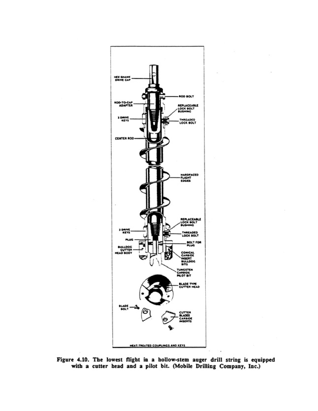
welded onto larger diameter pipe with a cutter head mounted at-the bottom (Figure 4.10). Unlike the
solid-stem method, drill rods (drill stems) can pass through the center of the auger sections. A plug is
inserted into the hollow center of the cutter head to prevent soil from coming up inside the auger. This
center plug has an attached bit that helps advance the auger. The drill rod and plug connect through the
auger flights to the top-head drive unit by small-diameter drill rods to insure that the drill rods and plug
rotate with the flights.
Hollow-stem augers with outside diameters ranging from 6-1/4 to 22 in (2-1/2 to 13 in ID) have been
used to drill water wells, although the common outside diameters are 6-1/4 to 13 in ID. Auger lengths are
usually 5 ft. but on larger hollow-stem rigs, especially those equipped with carousel racks, the auger
flights are 10 ft long and are stored in 20-ft sections. Holes as deep as 300 ft have been drilled with 6-
1/4-in diameter hollow-stem augers; more corrosion depths in stable formations are 120 ft with 6-1/4-in
diameter hollow-stem augers and 40 ft with 12-in diameter hollow-stem augers. Hollow-stem augers are
more effective than solid-stem augers because they can be used as temporary casing to prevent caving
and sloughing of the borehole wall. The hollow-stem method is a fast and efficient means of drilling and
completing small diameter wells to moderate depths. Screens can be installed and filter packed without
using casing or drilling fluids. Use of the hollow-stem auger method is also particularly advantageous in
obtaining accurate samples. A major disadvantage of this method is the relatively high cost of
hollow-stem flight augers.
Page 64 of 360
Page 65 of 360
4.9. DRILLING PROCEDURES WHEN BOULDERS ARE ENCOUNTERED
In many formations, boulders or large cobbles can slow or even stop drilling progress regardless of the
drilling method being used. If the casing or borehole is being deflected, the driller must do something
about the boulders before drilling can be continued. Boulders occur commonly in glacial tills, extremely
coarse outwash deposits, former beach zones now buried, conglomerate deposits that formed near the
base of steep slopes, alluvial fans, and alluvial deposits in mountainous regions. Drilling costs can rise
significantly when boulders are encountered in the hole.
In general, do not drill below a protruding boulder because it may fall pardy into the hole causing the bit
to become lodged. Whether boulders are removed or destroyed will depend on the drilling method being
used. Alternative procedures include the following:
4.9.1. Cable Tool:
1. Change the bit.
2. Increase drill-string weight to break the rocks.
3. Bail out material below the boulder so that it drops into the hole. Fluid levels may have to be increased
to keep the borehole open.
4.9.2. Direct Rotary:
1. Increase the weight on the bit to grind through or crush the rock or force it to the side of the borehole.
2. Install a new or different bit.
3. Fish out the boulder if it is completely within the borehole.
4. Switch to air and use an air hammer.
5. Cement the boulder if it is sufficiently far above the aquifer, then continue drilling.
4.9.3. Reverse Rotary:
1. Install a new bit to either push the boulder into the borehole or grind up the rock, cement can be used
to stabilize the rock (if boulders are not near the aquifer).
2. Increase the weight on the bit.
3. Fish out the boulder.
4.9.4. Air Rotary with Casing Driver:
1. Keep the bit close to the bottom of the casing so boulders cannot become lodged between the bit and
casing.
2. Drill and drive only short distances.
3. Increase the weight on the bit.
4. Pull back slightly allow the boulder to fall into the borehole or be pushed into die borehole wall.
5. Change the bit, preferably to a down-the-hole hammer.
6. If boulders are sufficiency far above the aquifer, cement them into position so they can be drilled.
4.9.5. Several general points can be made concerning drilling through boulders:
Page 66 of 360
1. The driller should proceed cautiously to prevent damaging the drive shoe or deflecting the casing.
2. It may be best to case through boulders.
3. Drill at least 5 to 10 ft into the rock to make sure that bedrock has been reached.
4. If the casing has been dented by a boulder during driving, the casing diameter should be restored by
using a casing swedge (the swedge is also useful in lining up broken casing so it can be lined with a
sleeve).
4.10. FISHING TOOLS
In most drilling methods, tools can be broken off or dropped into the borehole. The object or tool that is
lost-in the hole is called the "fish," which the driller retrieves by "fishing." Fishing jars are used in the
cable tool method to retrieve tools from the hole. They are placed between the fishing stem (usually 10 ft
long) and a fishing tool such as a ham socket or center spear. In this position, the stem increases the
impact of the jars on the fishing tool during the upstroke. The greater stroke of the fishing jars prevents
accidental downstroke hitting during retrieval of the lost tool. Hitting both up and down will usually free
the "fish" to be removed from the hole.
In the rotary drilling method, the shear stresses placed on the drill string are often excessive, unlike the
cable tool method where only the force of gravity is utilized for drilling. These shearing stresses are
magnified because the weight of the entire drill column is augmented by the hydraulic driven pull-down
weight that may be applied by the driller. These pull-down weights may reach 30,000 lb or more.
Because the torque applied to the drill string can occasionally exceed the breaking strength of the
equipment, special fishing tools have been developed to extract pieces of the sheared drill string from the
hole.
Six fishing tools are used most commonly in rotary drilling operations: tapered tap, die collar, releasing
spear, junk mill, circulating overshot, and magnet. Many drillers construct fishing tools that may be
particularly suitable for their own equipment. After determining the depth at which the string or tool has
been lost, the driller attempts to enter or overshoot the top of the lost drill rod and then rotate the fishing
tool until it is firmly attached. Releasing spears can be used in place of a taper tap. They offer the
advantage of quick release from the fish and provide easy re-engagement if necessary. If greater force is
required to pull the fish, another type of tool called a releasing and circulating overshot is used. It
consists of three main components—a top sub, a bowl that houses the engaging and packing-off element,
and a "guide to center the tool over the fish. A junk mill is used to grind up smaller objects lost in the
borehole. Powerful magnets are useful in moving relatively small tools or other parts from the hole. To
be successful, circulation must be established or maintained during most fishing operations.
One particularly common fishing operation in large-diameter holes involves retrieval of roller cones that
have become detached from the bit. Failure of the bearings on which the cones rotate is the principal
cause of cones falling to the bottom of the borehole. Bearing failure is usually attributable to excess
weight on the bit, high operating temperatures, or excessive use. The most common techniques for
retrieval of lost cones include the use of a junk basket, a strong magnet, or a button or diamond bit to
grind up the cone. Lost cones can sometimes cause abandonment of the well. To avoid this problem, the
driller should immediately replace any bit on which a cone has become damaged or locked in place.
4.11. GRATING AND SEALING WELL CASING
Page 67 of 360
In engineering practice, grouting is the act of injecting certain substances into the void space of earth
materials to reduce or eliminate their permeability, consolidate them, or increase their strength (Bower,
1981). Thus, grouting is widely used in constructing tunnels, dams, bridges, and foundations for
buildings. Low-viscosity grouting materials are used in soils having low hydraulic conductivity, whereas
high viscosity grouts are used in coarse-grained, highly permeable soils. Although several basic types of
grouting materials exist, multiphase (suspension) systems are common in the water well industry.
Grouting (cementing) well casing involves filling the annular space between the casing and the drilled
hole with a suitable slurry. The term "grouting" is used by drillers to describe the process of mixing and
placing grout. The length of the borehole section to be grouted will vary according to well codes, aquifer
structure, and water quality.
Wells constructed in rock that is overlain by relatively thin, loosely consolidated sediment will usually
be grouted from the surface to the rock. In some formations where poor-quality aquifers are interspersed
with high-quality water zones, the poor-quality aquifers are cemented off. Grouting is also standard
practice in monitoring well construction.
The grouting methods described below focus primarily on the use of cement and water (neat cement),
although the slurry may contain sand and bentonite. A clay slurry made with a high-grade bentonite can
serve for grouting, provided it is used at a depth where drying and shrinking of the grout will not occur,
and where water movement will not wash away the clay particles.
Various types of cement are manufactured to accommodate different chemical and physical conditions
found in the subsurface environment. Five types are given in ASTM specifications and are used
generally at the ground surface. The high pressures and temperatures encountered in deep wells,
especially oil wells, has led to the development of eight classes of cement under API specifications.
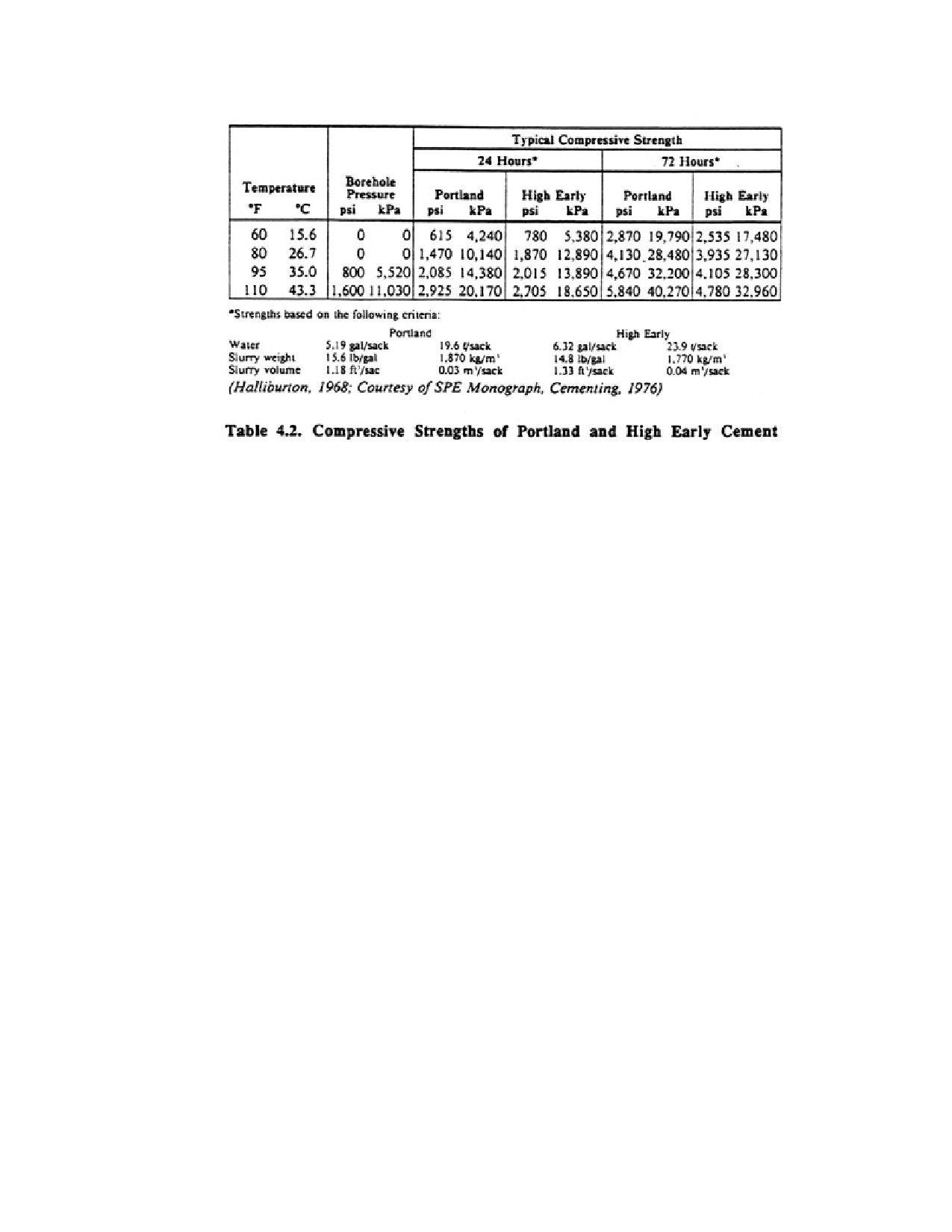
The compressive strengths of portland (types A and B) and high early cements (type C) are shown in
Table 4.2 for setting times of 24 and 72 hours at various temperatures. Various compositions of cement
have different compressive and tensile strengths after curing; compressive strengths are usually about 10
times greater than tensile strengths. For most drilling operations, the cement should reach a compressive
strength of 500 psi before drilling is resumed. The temperature in the borehole, chemistry of the
formation water, dilution of the cement, and downhole pressure affect the rate at which the cement cures.
Generally, the 500 psi compressive strength is reached between 12 and 24 hours after placement.
The chemical reaction that causes gout to set and harden begins as soon as cement and water are mixed
The equipment used to mix and place the grout must be adequate to complete the installation while the
grout is still fluid.
The size of the annular space required for grouting depends on the method of grouting. Thus, planning
the size of the borehole is important. The annular space to be grouted should have a diameter that is 2.0
to 8.0 in larger than the casing. The ideal result is a uniform sheath of cement around the casing for the
entire vertical distance to be grouted. Tight places and "dead spots" result where casing not properly
centered touches the wall of the hole, causing channeling of the slurry.
Page 68 of 360
State or federal laws may dictate the minimum length of grout required for various casing diameters for
certain types of wells. The drilling contractor should become familiar with specific regulations for the
type of wells drilled.
4.11.1. Proportioning Cement Grout
Laboratory tests indicate that 5.2 gal of water are needed to hydrolyze one 94-1b sack of portland
cement. This mixture produces a slurry weight of 15.6 lb/gal. An advantage of using the proper
water-cement ratio is more effective bridging of cement particles in the pores of permeable formations,
which prevents excessive penetration of the grout into these formations. Although thinner mixtures with
more than 6 gal per sack are used for grouting foundation materials, this ratio is less suitable for well
work. Shrinkage increases with greater water content, because water is squeezed out of the thinner
mixtures by pressure against fine sand or other permeable formation materials. Cement will settle out of
the slurry if the ratio is greater than 10 gal per sack of cement. Water used for grout should be free of oil
and other organic material.
Bentonite clay can be added to the cement to hold cement particles in suspension, reduce shrinkage, and
improve fluidity of the mixture. Approximately 3 to 5 lb of bentonite should be mixed with 6.5 gal of
water per sack of cement. If the amount of bentonite exceeds 6 percent, excessive shrinkage of the
cement will occur. It is best to mix the bentonite and water few, then add cement to the clay-water
suspension.
4.11.2. Mixing the Grout
It is important that grout be mixed thoroughly and be free of lumps. Some drillers use small portable
grouting morphines that combine both the mixing and pumping operations. Many of these machines are
equipped with a positive displacement pump because this type of pump can work efficiently against
much greater head pressures with lithe loss in emplacement volume. Most drillers avoid using the mud
pump on their rotary rigs because of the abrasive qualities of the cement and the difficulty in removing
all traces of the cement from the pump after completing the cementing operation.
Page 69 of 360
The volume of grout required cannot always be determined accurately. Regularities in the size of the
borehole and losses into fractured rock occur in many wells. Therefore, the driller must be prepared to
augment initial estimates on short notice.
When water is mixed with cement and hydration occurs, heat is released. The amount of heat released is
a function of the volume of cement—the more cement, the more heat. If the formation temperature is
high, the hydration process is accelerated and heat is released more quickly. If cement fills a 2-in
annulus, the heat produced during hydration creates a maximum temperature rise of 35° to 45°F.
4.11.3. Slurry Placement Methods
Successful placement of the cement will depend on the temperature and pressure in the borehole, how
well the casing is centered in the hole, and the emplacement method. Temperature has a significant effect
on how fast the cement slurry hydrates and thus how fast the cement develops strength. Pressures caused
by the weight of the drilling fluid can reduce the rate at which the cement can be pumped. At high
pressures (only a problem in deep water wells), the hardening time for the cement can be substantially
reduced. The use of centralizers is important to assure a uniform thickness of cement around the casing.
Centralizers should be placed every 40 ft on the casing. Several placement methods are described below.
Each method is satisfactory but care should be taken to assure that channeling does not occur, thus
avoiding gaps in the cement.
To assure that grout will provide a satisfactory seal, it is necessary to place it in one continuous
operation, before setting begins. Regardless of the grouting method used, the grout should be introduced
first at the bottom of the space to be grouted. This procedure minces both contamination or dilution of
the slurry and bridging of the mixture. If the cement is pumped under turbulent flow conditions, drilling
fluid removal is enhanced and voids are filled more completely.
Moyno, diaphragm, and piston pumps are most often used to pump cement grout. The Moyno pump is a
positive displacement pump with an effective output pressure of 225 to 250 psi; it cannot be permitted to
pump sand, however. Diaphragm pumps, although having lower output pressures of 100 to 110 psi, can
handle particles up to 1/4 to 3/8 inches in diameter. They are not as efficient as the Moyno pump because
of higher friction losses. Both types are used for batch mixing.
For larger grouting jobs, either piston pumps or, less frequency, centrifugal pumps are favored. Piston
pumps of various sizes (2 x 3, 3 x 4, or 5 x 6) can build pressures to 120 psi, and have been used
successfully to place grout to 3,000 ft or more with a 2-in tremie pipe.
In cases where an open borehole has been drilled below the depth to which the casing is to be grouted,
the lower part of the hole must be backfilled, or a bridge (cementing basket or formation packer shoe)
must be set in the hole, to retain the slurry at the desired depth.
When the borehole cannot be backfilled, external packers combined with a float shoe or cement baskets
are used to support the cement column. Cement baskets are installed on the outside of the casing by
clamps. External packers must be installed in the casing string as the casing is run into the borehole; the
packers are expanded before cementing begins.
Cement should be allowed to harden for 24 hours before drilling resumes, although some types of
cement may require longer curing times.
4.11.4. Tremie Pipe Outside Casing
Page 70 of 360
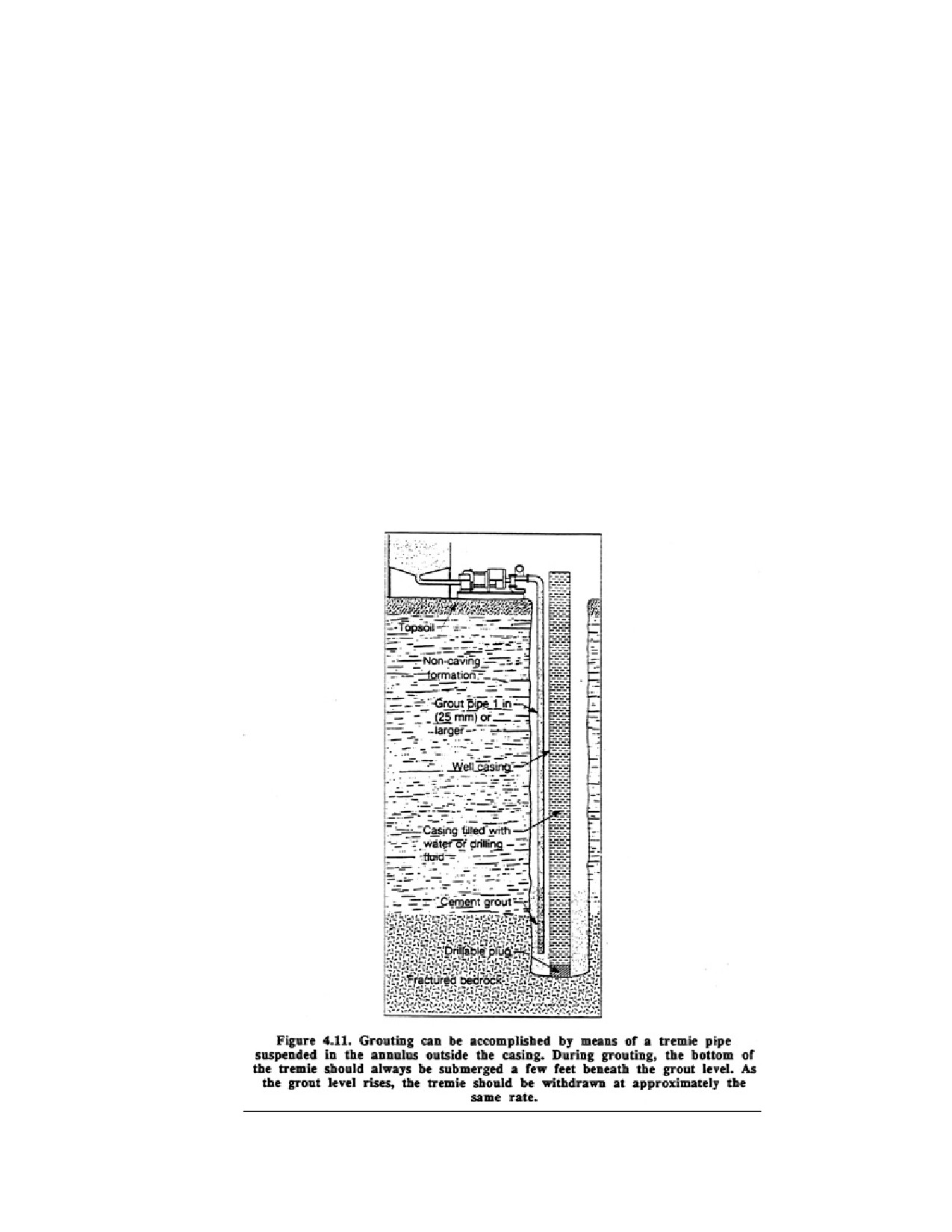
Grout can be placed through a string of small diameter pipe (tremie or grout pipe) placed outside the
casing. The casing is lowered into the hole with centering guides attached. Care must be taken to align
the centering guides along the entire length of casing to be grouted so that the tremie pipe can pass by
them. The lower end of the casing should be closed with a drillable plug or driven into clay so the grout
cannot enter. To overcome the buoyant effect of the slurry, the casing may be filled with water or be held
down by the weight of the drill rig.
Grout can be placed by gravity through a tremie pipe, but pumping is preferred because the required
volume of grout can be introduced rapidly and with little chance of leaving voids in the grout. Pump
pressure must equal the hydrostatic pressure of the Bout the fluid friction in the grout pipe and annular
space.
For shallow holes where the grout is placed by a positive displacement pump, the cementing operation
may be completed in a single step; that is, the position of the tremie pipe is not changed as the annulus is
filled. If a centrifugal pump is used or if the hole is deep, the tremie must be raised periodically so the
hydraulic head created by the cement does not exceed the working pressure of the pump. Usually the
tremie is withdrawn one or more joints at a time, but the bottom
of the tremie should always remain beneath the surface of the cement. The rate of tremie withdrawal will
depend on the pumping rate and the volume of the annulus. The depth to the top of the grout can be
Page 71 of 360
detected by using a weighted line or a weight indicator. The volume (and therefore the height) of the
grout can also be estimated by knowing the volume of material in the hopper before grouting begins.
The grout pipe must be large enough so that all the grout can be placed before hardening begins. A 3/4-
or 1-in grout pipe may be used, although 2 in pipe is used for deeper holes. The borehole should be 4 to 8
in larger than the casing to accommodate the grout pipe. Initially, the pipe should extend to the bottom of
the annular space and should remain submerged in the slurry while the grout is being placed (Figure
4.11). Should the tremie become plugged, the output pressure can be increased, the tremie can be raised
to reduce the pressure at the bottom of the line, or it can be vibrated or struck to dislodge the stuck
material. If operations are interrupted for any reason, the pipe should be raised above the grout level and
not be lowered into the slurry again until all air and water in the pipe have been displaced by grout.
4.11.5. Tremie Pipe Inside Casing (Inner String Method)
Page 72 of 360
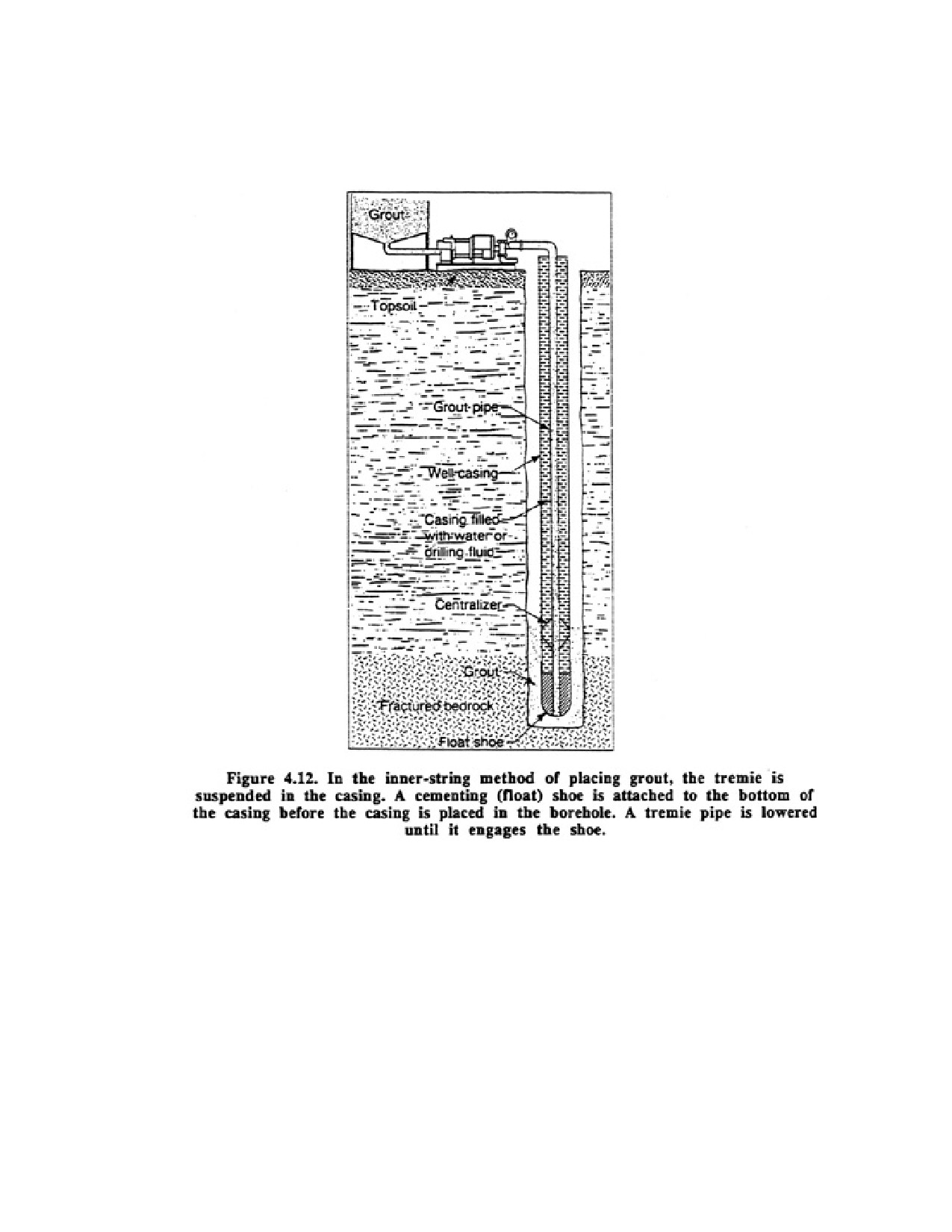
When the use of a grout pipe outside the casing is impractical, grouting may be done by using a grout
pipe installed temporarily within the casing (Figure 4.12). In the oil-well industry, this is referred to as
the inner-string method of cementing. A cementing plug (float shoe) is attached to the bottom of the
casing, which permits the grout to pass into the annular space but prevents it from leaking back into the
casing while grouting or after removing the grout pipe.
In the grouting process, the casing is filled with water and suspended just above the bottom of the
borehole. Grout is pumped through the grout pipe and—float shoe and forced upward around the casing.
When cement appears at the surface, displacing all other fluid in the annular space, the grout pipe is
disconnected from the float shoe. Cement is washed out of the pipe by pumping water through it before
removing it from the well. Because calcium residues may have a deleterious effect on the
viscosity-building characteristics of some drilling fluid additives, the casing should be completely
flushed with clean water after completing the cementing operation.
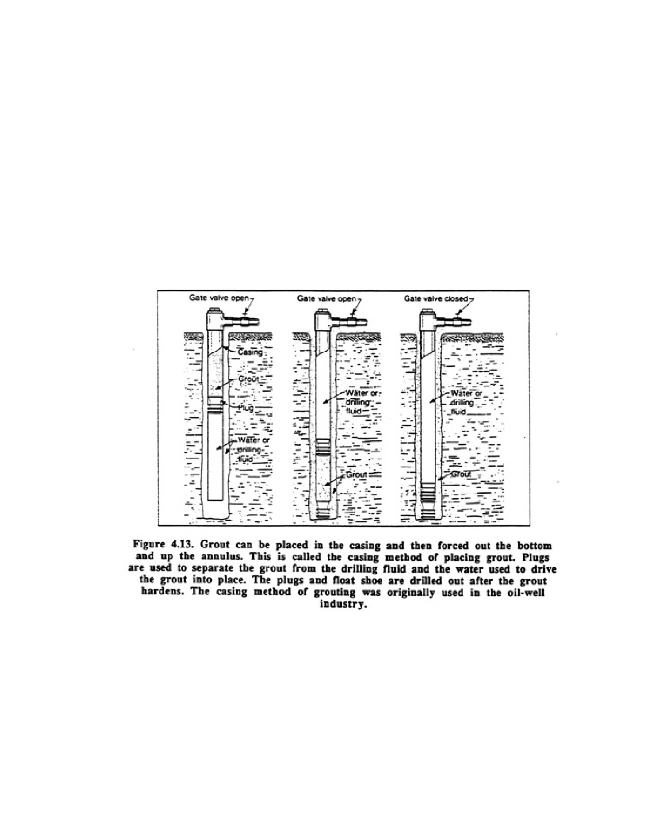
4.11.6. Casing Method of Grouting
The casing method of grouting, in which the slurry is forced down the casing and into the annular space,
has been adopted from the oil-well industry. In one method, two spacer plugs are used. One plug,
introduced first, separates the cement slurry above from the drilling fluid in the caning; the other
separates the slurry from water pumped in above it to wash the slurry from the casing (Figure 4.13).
After punning water or drilling fluid through the casing to circulate fluid in the annular space and clear
any obstructions from the hole, the first plug is inserted and the casing capped. A measured volume of
grout is then pumped in, the casing is opened, a second plug is inserted, and the casing recapped. A
measured volume of water is then added and pushed to the bottom of the casing, forcing most of the
Page 73 of 360
cement slurry from the casing and into the annular space. The water in the casing is held under pressure
to prevent backflow of the slurry until it has set and hardened. When the cement has hardened
sufficiently, the second plug and any cement remaining in the casing are drilled out, drilling is continued
below the grouted section, through the first plug and into the formation.
A modification of the double-plug procedure is favored by many drillers. After pumping a predetermined
quantity of grout into the casing, a plug is installed on top of the grout and enough water is added to
force most of the grout from the casing. The usual practice is to leave 10 to 15 ft of grout in the casing. If
only a single plug is used, that part of the slurry diluted by the drilling fluid must be expelled to waste at
the surface so that a sound, uncontaminated grout seal is achieved at the upper end of the casing. The use
of a plug insures slurry and water separation, resulting in a proper grout seal at the lower end of the
casing. To eliminate over or under displacement of the cement, a landing collar is set 10 to 20 ft above
the bottom of the casing to stop the drivable plug at the appropriate depth.
Spacer plugs should be made of materials that can be drilled easily (wood and cement are often used).
When a plug settles on sand or clay, the cushioning effect of the soft formation permits the plug to sink
into the formation before it iS drilled out.
4.11.7. Grouting Failures
Several factors may contribute to grouting failures. Some common problems are premature setting,
partial setting, insufficient grout column length, voids or gaps in the grout, excessive shrinkage, and
casing collapse. Premature setting of the cement can be a serious problem and is usually caused by
incorrect assumptions concerning borehole temperature, or by hot mixing water, improper
water-to-cement ratios, contaminants in the mixing water, mechanical failures, and interruptions of the
pumping operation. Voids within the grouted annulus, another major grouting problem, are usually
caused by contact of the casing with the borehole wall or by the presence of washouts.
4.11.8. Installation of Bentonite Grout
Bentonite (essentially montmorillonite) is widely used as a grouting material, especially for monitoring
wells and water wells where surface contamination may occur, because of its low cost and ease of
placement. Commercial bentonite used for grouting is available in either pelletized or granular form.
When either of these forms are mixed with water, they begin to hydrate within seconds. Thus, it is
impossible to place the granular form by dropping the particles into the annulus. Even pellets dumped
down the annulus will begin to stick together and to the walls of the annulus within a few feet of the
surface, and therefore may bridge high above the intended depth. It is possible to freeze the pellets first
and then carry them to the drilling site in a cooler containing dry ice. In this condition, the pellets will
settle a greater distance before sticking. The pellets can also be cooled with liquid nitrogen; in this case,
an icy outer layer forms which further protects the pellets so that they may fall 40 ft or more before
hydration begins. In general the pellets should always be tamped into place to eliminate any bridging that
may have occurred. A much better practice is to pump a prepared bentonite slurry by means of a tremie
pipe, using a Moyno pump (40 to 60 gpm) or diaphragm pump (60 to 100 gpm). If the mixture of
bentonite (usually granules) and water is used, only 1 lb of bentonite can be mixed per gal of water
because the resulting viscosity will be at the limit of pumping capacity. After being placed, grout with
this concentration of bentonite may eventually shrink 25 percent, even though the ground around the
grout usually remains somewhat moist. This is a highly unsatisfactory shrinkage rate. Virtually no
shrinkage will occur in grout mixed at concentrations of 1.5 lb bentonite per gal of water. This
concentration can be pumped only if the water has been pretreated with 1 qt of polymer per 100 gal. The
Page 74 of 360
polymer prevents the clays from hydrating immediately, and once the particles are evenly distributed in
the water the viscosity remains low enough so the slurry can be pumped for about 20 minutes. The
granular Bentonite should be mixed gently into the water with a paddle, not a mixer or pump; these latter
devices will break up the particles and cause the viscosity of the slurry to increase prematurely.
Bentonite grouts should be mixed in batches so they can be pumped before the slurry becomes too
viscous. Ideally, the diameter of the suction hose should be as large as possible. In most cases, the slurry
reservoir is above the pump intake so that hydrostatic pressure created by the reservoir makes the pump
operate more efficiency. The pump and all piping should be flushed with clean water after each batch of
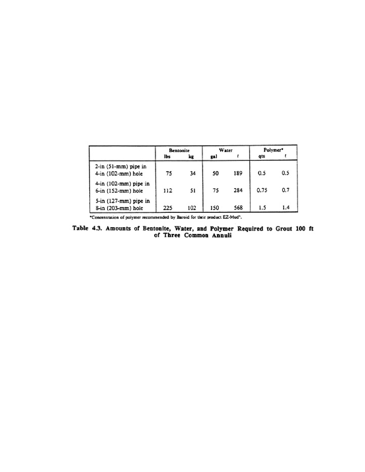
grout is pumped into place. The volumes of bentonite, polymer, and water for various annulus sizes, per
100 ft of depth, are given in Table 4.3.
Bentonite grout has several advantages over cement grout. It has a faster setting time, no heat of
hydration, a lower hydrostatic pressure (specific gravity is 9.2 for the grout given in Table 4.3), and the
cost is one-third that of cement. Also, Bentonite will adhere to both walls of the annulus, whereas cement
will adhere finely only to the soil.
There are several 1imitadons on the use of Bentonite grout. Bentonite grouts cannot be used when the
borehole is underreamed, because the "set" taken by the grout is not sufficient to withstand the vertical
hydrostatic pressures. Thus, the grout may eventually flow into the underreamed section.
Another limitation is that Bentonite gout should not extend so close to the ground surface that it can dry
out and shrink because of low soil moisture. Cement is always used at or near the top of the borehole.
The presence of salt water will cause Bentonite grout to flocculate and thereby lose viscosity. Organic
acids can also destroy the impervious character of the grout seat
4.12. PLUMBNESS AND ALIGNMENT
A well should be both straight and plumb, although in practice any borehole of substantial depth may not
be perfectly straight perfectly plumb. A straight well is one in which each casing section is joined to
adjacent sections in a manner that maintains perfect alignment. A borehole that is plumb is one whose
center does not deviate from an imaginary vertical line running from the ground surface to the center of
Page 75 of 360
the Earth. A well bore may be straight, but not plumb; if the borehole is plumb, however, it will be
straight. Some tolerance or deviation in straightness (alignment) and
Page 76 of 360
plumbness is normally allowed in practice. By custom, a deviation from plumbness of two-thirds the
well's inside diameter per 100 ft is allowed and thought to be reasonable, considering the inherent
difficulties of drilling in earth materials. The U.S. Environmental Protection Agency (1975) has
suggested that wells should be constructed so that the borehole deviation from plumbness is 1 degree or
less per 50 ft when using drift indicators.
Page 77 of 360
Of the two factors, straightness of the well bore is the most important.
Some conditions that cause wells to become misaligned and out of plumb are (1) character of the
subsurface material (faults, boulders in the borehole, inclined strata), (2) too much or too little weight on
the drill bit, (3) trueness of the casing and drill pipe, and (4) the pull-down force applied to the drill pipe
in rotary drilling. While the force of gravity tends to make the drill bit cut a vertical hole, the varying
hardness of different materials being penetrated deflects the bit from a truly vertical course. In glacial
drift, the edge of a boulder can deflect a cable tool or rotary bit. In cable tool drilling, a boulder may
deflect the well casing, causing the hole to drift increasingly as the well is deepened.
When drilling by the rotary method, too much force applied at the top of the drill stem will bend the
slender column of drill pipe. This tends to cause the bit to cut off center. Heavy drill collars in the lower
part of the drill stem help to put weight just above the bit, which overcomes the tendency to drift off a
true vertical course. They are also more rigid than ordinary drill pipe, and thus help keep the lower part
of the drill string straight. Large stabilizers are also used by many drillers to keep holes straight.
In recent years, special deviation instruments have been developed to measure the misalignment that
occurs during drilling. A deviation survey is conducted along with the standard suite of logs after the
maximum hole depth has been reached.
4.13. CONCLUSIONS
Selection of the best drilling method for a particular job requires an understanding of the geologic
conditions and the physical limitations of the drilling rig. In addition, the value of experience cannot be
overestimated, for many drilling difficulties occur because either the driller is unprepared to handle the
wide range of subsurface conditions or has pushed the rig beyond safe operating limits. Good record
keeping, patience, and a willingness to learn are some important characteristics of good drillers; the age
of the machine or the particular drilling method used are of secondary importance in drilling successful
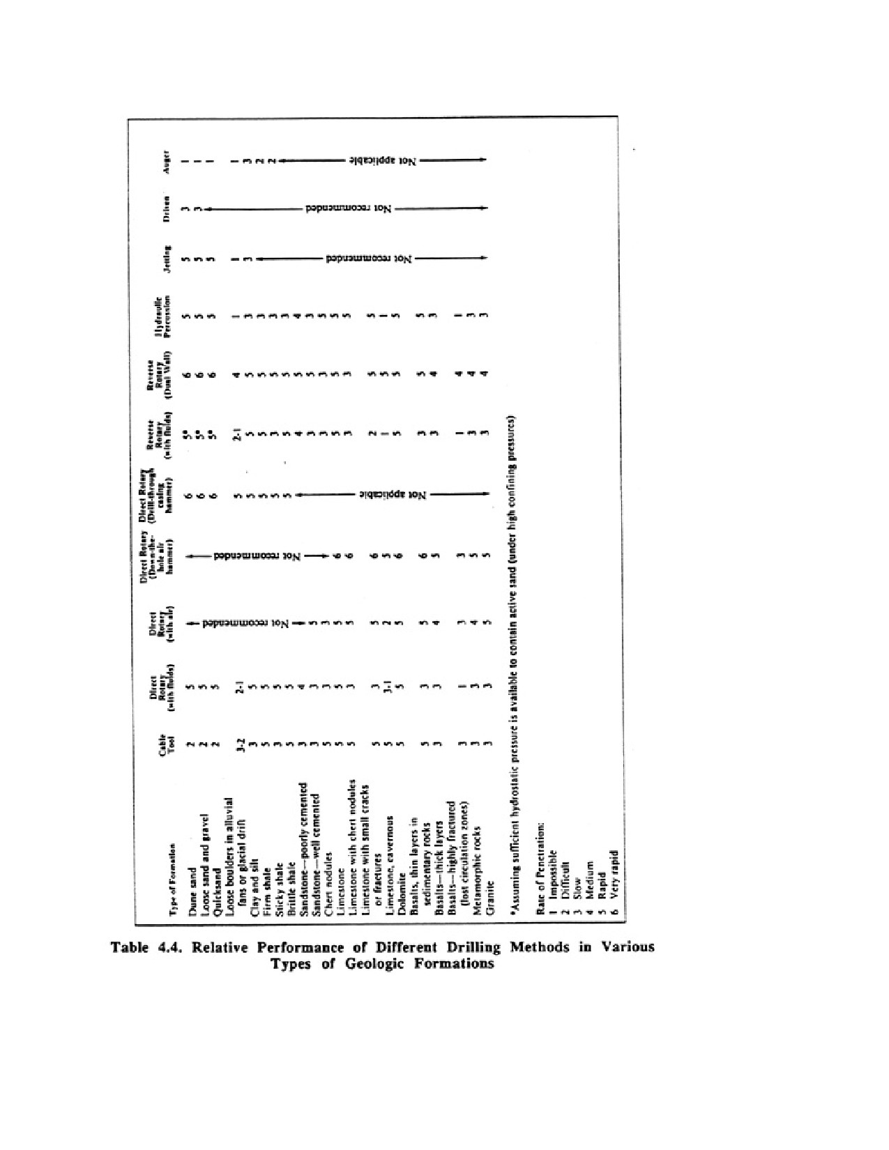
wells. Table 4.4 gives the drilling performance of different drilling methods in various geologic
formations. The relative performance differences between drilling methods, however, will also depend
on the experience of the driller, the presence of geologic anomalies at the site, and the pressure
conditions affecting the groundwater.
CHAPTER 5.
DRILLING FLUIDS
The technology of drilling fluids has advanced as rapidly and extensively as the rotary drilling machine.
In the late 19th century, water alone was the principal fluid used in rotary drilling, although some
entrainment of natural clay particles into the fluid must have occurred much of the time. The general
term "mud" originated when certain kinds of clays were added to water to form drilling fluid. Recent
advances, however, have made the term "mud" somewhat obsolete. Modern mud systems are now
referred to as drilling fluids because of the large number of additives that can be used to impart special
properties to drilling fluids. Much of the progress in drilling fluid development has occurred in the oil
industry and has been applied thereafter in the water well industry. Today, the drilling fluid system can
represent a major cost for deeper rotary-drilled holes; therefore, the economic success of the drilling

Page 78 of 360
operation may be determined by the contractor’s ability to control the physical characteristics of the
drilling fluid.
5.1. TYPES OF DRILLING FLUIDS
Drilling fluids used in the water well industry include water-based and air-based systems (Table 5.1).
Water-based drilling fluids consist of (1) a liquid phase, (2) a suspended-particle (colloidal1) phase, and
(3) cuttings entrained during drilling. The colloidal phase may range from less than 1 percent to as much
as 50 percent by volume. Air-based drilling fluids may consist of only a dry air phase, but more often
they contain some water to which a surfactant (soap) is added to produce a foam. Occasionally a small
amount of clay or polymer may be added to stiffen the foam. Thus, the primary drilling fluids, water and
dry air, may be used alone, but a great variety of additives are available to modify their physical and
chemical properties so they will perform more satisfactorily.
1 Suspended particles that are approximately 0.0005 to 0.5 microns in size, do not settle out of the liquid
rapidly, and are not readily filtered.
(There are 25,400 microns per inch.)
Page 79 of 360
In this chapter, three major, but vastly different, types of drilling fluid additives are discussed and
contrasted---clays, polymers, and surfactants. Clays and polymers are commonly added to waterbased
systems and surfactants and occasionally clays or polymers are added to dry air systems.
Water with clay additives produces a high-solids drilling fluid, whereas a combination of polymeric
additives and water produces a low-solids drilling fluid. Many other special additives, such as
flocculants, thinning agents (dispersants), weighting materials, corrosion inhibitors, filtrate reducers,
lubricants, preservatives, bactericides, and lost-circulation materials, are used to further adjust the
properties of drilling fluids.
The exact driving fluid system selected will depend principally on the rock formation or stratigraphy
expected and the equipment available. Drilling in hard rock for example, requires procedures different
from drilling in sedimentary rock or unconsolidated overburden. Waterbased drilling fluid systems with
clay or polymeric additives are typically used in unconsolidated formations; air is used in
well-consolidated or semiconsolidated rocks and sediment; and clean water is used with reverse rotary
drilling equipment for large diameter wells in unconsolidated, semiconsolidated, and nonsensitive
(nonswelling) sediments.
5.2. FUNCTIONS OF A DRILLING FLUID
Drilling fluids can perform many functions, depending on the physical and chemical conditions found in
the borehole. The primary functions are:
1. Remove cuttings. The primary purpose of the fluid system is to remove cuttings from the borehole
during drilling. The rate at which cuttings can be removed depends on the viscosity, density, and uphole
velocity of the drilling fluid, and the size, shape, and density of the cuttings. Ideally, the fluid should
entrain the cuttings at the bit, carry them to the surface, and allow them to drop into a settling pit or tank
before the fluid is recirculated. Inefficient removal of cuttings can reduce the penetration rate of the drill
bit, adversely affect the physical properties of the drilling fluid, and increase the energy required to
recirculate the drilling fluid.
2. Stabilize the borehole. To maintain an open borehole, the drilling fluid stabilizes the borehole walls
and prevents expansion of swelling clays. When using water-based systems, the drilling fluid must
provide a pressure greater than that existing in the formations penetrated. The pressure exerted against
the borehole wall depends on the height of the fluid column and the weight of the drilling fluid. If water
is permitted to flow into the well bore from the penetrated formations, sloughing of the hole may occur,
resulting in lost time and increased driving costs.
Drilling fluids should prevent formation clays from expanding into the borehole during drilling. Some
hydrating clays can absorb large volumes of water, thereby increasing the physical dimensions of the
clay. To control this problem, the drilling fluid must isolate formation days from the water in the drilling
fluid. This is usually achieved by adding certain chemicals such as potassium chloride to water-based
drilling fluids that contain clay additives, or by using polymeric drilling fluid additives which coat the
formation clays and minimize swelling caused by hydration.
Page 80 of 360
3. Cool and lubricate the drill bit. Fluids circulating through the drill string cool and lubricate the bit,
thereby avoiding unnecessary bit wear and reducing maintenance.
4. Control fluid loss. All water-based drilling fluid systems must control drilling fluid loss in highly
permeable formations by creating a nearly impermeable clay filter cake or polymeric film on the
borehole wall. Insufficient filter cake or polymeric film deposition may allow excessive fluid loss or
even complete loss of circulation.
5. Drop cuttings into a sealing pit. As the drilling fluid is circulated through the sealing pit, cuttings
should drop out so they are not recirculated. The gel strength of the drilling fluid is the primary factor
controlling the rate of settlement. Gel strength is a measure of the fluid's ability to suspend cuttings when
the fluid is at rest. The flow rate in the settling pit is also important and is controlled by the shape and
size of the settling pit.
6. Facilitate acquisition of information about the formation being penetrated. Drilling fluid systems
should facilitate the recovery of representative cuttings and permit accurate geophysical logging of the
well.
7. Suspend cuttings in the borehole when the drilling fluid is not being circulated. During the time the
drilling fluid is not in motion, cuttings tend to settle in the borehole. If the rate of settlement is excessive,
cuttings may settle around the drill bit or stabilizer and jam the rotation of the drill string when drilling is
resumed.
During drilling, the principal objective is to maintain the drilling fluid in a suitable condition in spite of
changing downhole or surface conditions and the continuous addition of suspended drill cuttings. In
most cases, continuous monitoring of the drilling fluid is necessary to achieve the best results.
5.3. PROPERTIES OF WATER-BASED DRILLING FLUIDS
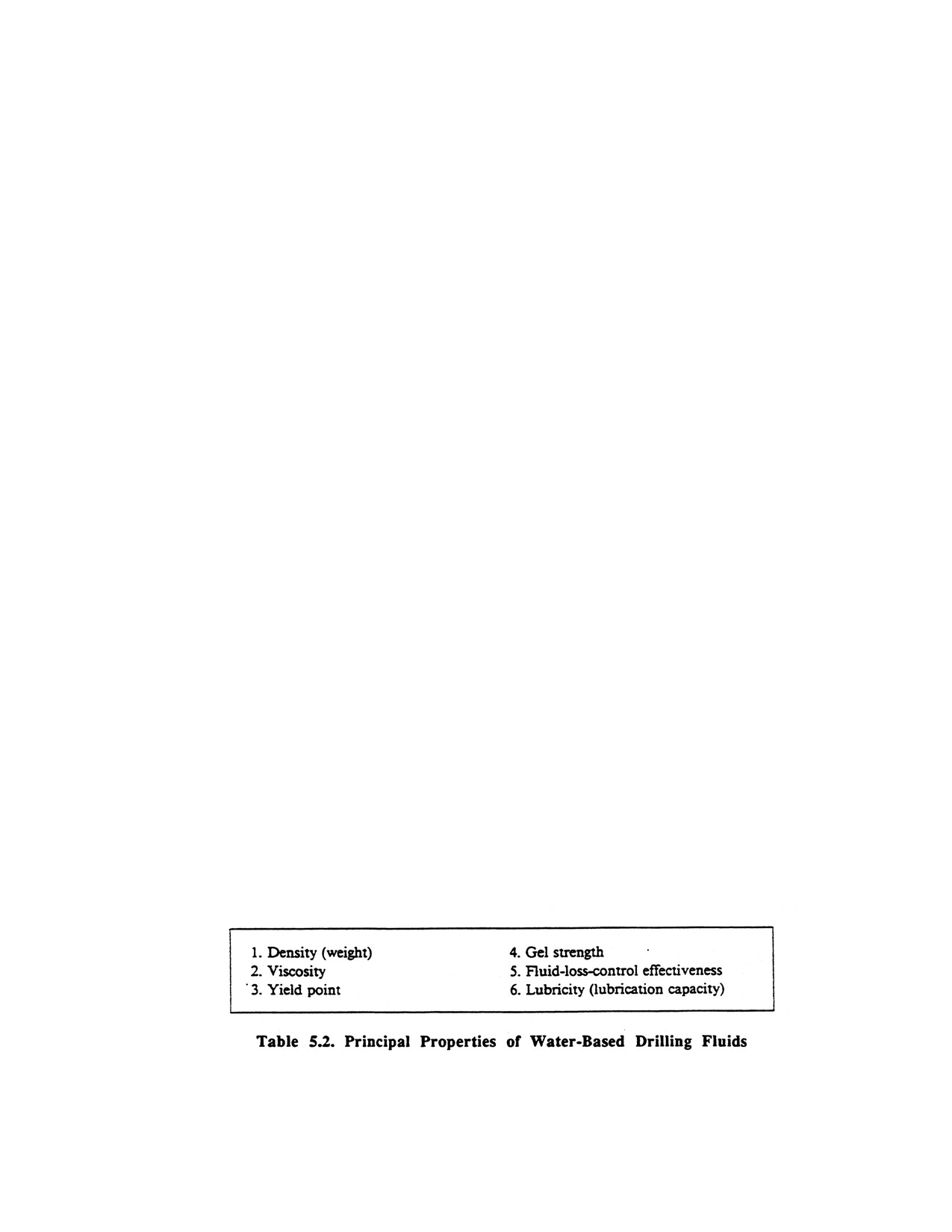
The drilling fluid properties listed in Table 5.2 should be understood thoroughly by the drilling
contractor. Regardless of which drilling fluid system is used, its effectiveness will depend upon the
contractor’s ability to anticipate the chemical and physical changes taking place during drilling and to
make modifications as required. At a minimum, all rotary drilling crews should be able to measure
drilling fluid density and viscosity, and understand the relationship of these properties to hole stability,
cuttings removal and fluid-loss control. The physical and chemical behavior of bentonite and polymers
differs significantly. These differences are examined separately as each drilling fluid property is
discussed below.
5.3.1. Density
Control of drilling fluid density is a fundamental factor in successful well drilling. Density is defined as
the weight per unit volume of fluid. Thus, the terms density and weight can be used interchangeably. In
Page 81 of 360
the English system, density is expressed in pounds per gallon (lb/gal) or pounds per cubic foot (lb/ft3).
The actual pressure exerted at any point in a borehole by a static drilling fluid depends on the fluid
density and the height of the fluid column above that point. Specific gravity is another way to express the
density of a drilling fluid. It is the ratio of the weight of a given volume of drilling fluid compared with
the weight of an equal volume of water. Drilling fluid density is measured easily with a balance scale.
Selection and maintenance of proper drilling fluid density prevents collapse of the hole and flow of water
into the borehole. To maintain an open borehole, the pressure exerted by the drilling fluid column must
exceed the pore pressure (water and gas) in the aquifer. Typically, a minimum excess pressure of 5 psi is
desirable, although this pressure requirement may be higher when pressures from confined formations
are encountered.
The drilling contractor should be able to calculate the downhole pressures exerted by the drilling fluid at
rest to determine whether the hydrostatic pressure is sufficient to control the pore pressure in the
formation. A simple equation for determining the hydrostatic pressure exerted by the drilling fluid in a
borehole is given by
Hydrostatic pressure =fluid density • height of fluid colwnn • 0.052
where hydrostatic pressure is in psi, density in lb/gal and height in ft.
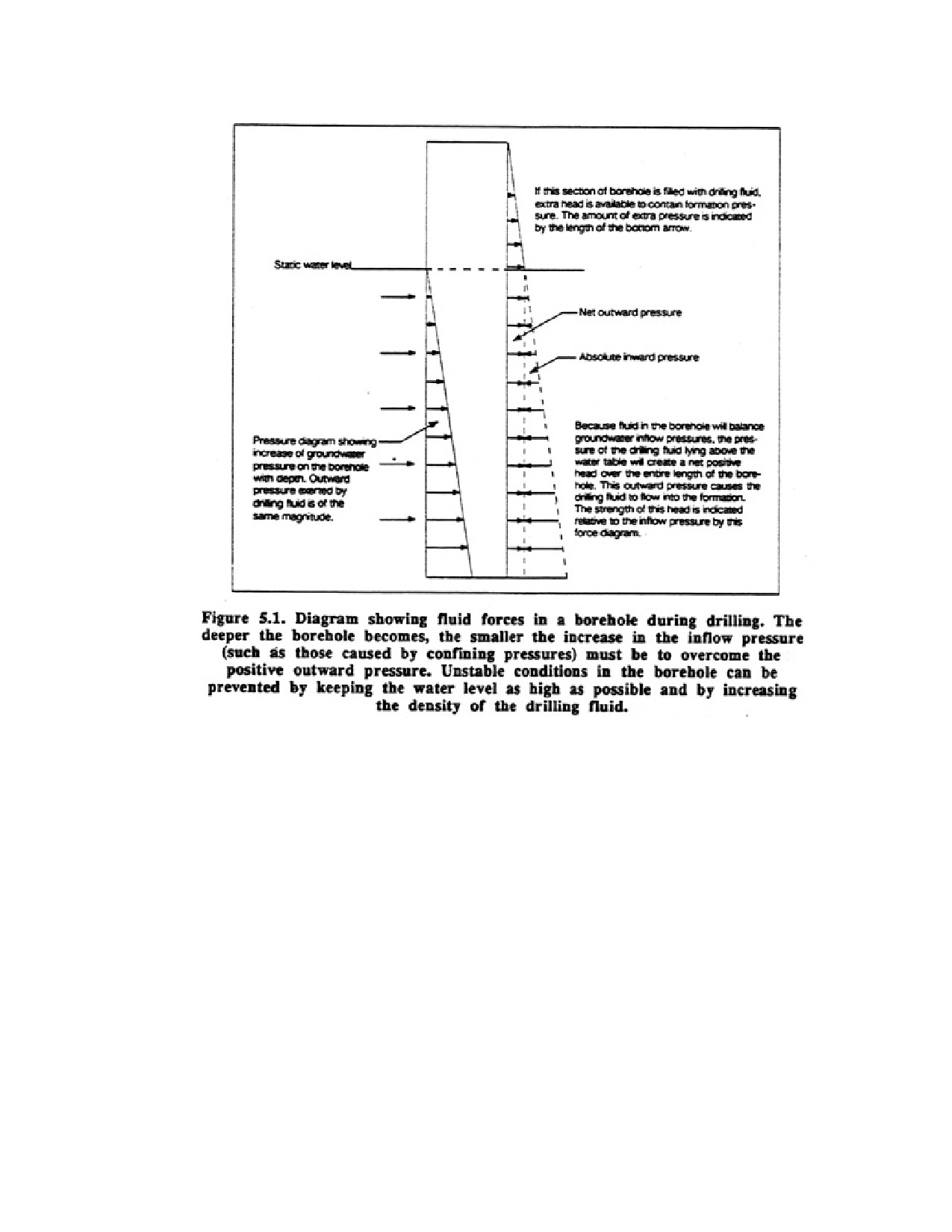
Under most drilling conditions, the hydrostatic pressure exerted by the weight of the drilling fluid
column above the static water level in the borehole is sufficient to create positive pressures in the
borehole; that is, the hydrostatic pressure created by the drilling fluid is great enough to keep the
borehole open (Figure 7.1). When static water levels are high, however, the weight of the drilling fluid
column above the static water level may not be sufficient to keep the borehole open.
Page 82 of 360
Under ordinary conditions, the maximum density that can occur in a clay system as a result of the
entrainment of solids during drilling is about 11 lb/gal. Further increases in density while maintaining a
proper solids/fluid ratio requires the introduction of higher density material so that less solids by volume
are needed for a specific density. Barite, wide a specific gravity of 4.2 to 4.35, is a standard weighting
material and is much heavier than clay additives and most formation materials, which have specific
gravities of 2.6 to 2.7. Barite particles are sized so as to remain suspended in the drilling fluid, but are
not small enough to affect the flow characteristics of the fluid.
To control the flow of water into the borehole, the contractor should increase the density of the drilling
fluid before reaching the confined formation. The additional drilling fluid density required to equalize
the confined pressure is determined by:
Drilling fluid density = weight of water · height of water above-ground level depth to top of confined
aquifer
The calculated drilling fluid density will only balance the confined pressure, however, and thus a safety
factor of 0.3 lb/gal is usually recommended. The total added density should be enough to control any
potential collapse of the formation during circulation of the drilling fluid and withdrawal of the drill
pipe.
Page 83 of 360
During the drilling process, solids generally begin to accumulate in the drilling fluid, causing the density
to increase. If silt, clay, or weakly consolidated shale is present, the density increase may be significant
and water must be added or solids removed to reduce the solids/fluid ratio. Too great an increase in
density can affect the drilling and well completion processes in the following ways:
• Large volumes of drilling fluid and cuttings can be forced into the aquifer during drilling.
Removal of the drilling fluid and cuttings during development can be extremely difficult,
especially if clay additives are used.
• Material costs increase because of high fluid losses, particularly in areas where mix water is
expensive or must be hauled long distances.
• Rate of penetration is reduced.
• Sample collection is more difficult and less reliable because cuttings do not drop out of the
drilling fluid at the surface.
• Wear on a mud pump is increased because it must keep recirculating the high volume of
unnecessary solids.
• Pumping costs increase because solids are continually recirculated.
5.3.2. Flow Characteristics of Drilling Fluids
The flow characteristics of a drilling fluid—viscosity, gel strength, and yield point—depend primarily on
the size, shape, and molecular structure of the particles in the fluid. Clay particles are less than 4 microns
in size, silt and barite are 4 to 63 microns, and fine to medium sand is 63 to 500 microns. The silt, and
barite if present, provide mainly density, whereas the clay particles enhance the viscosity and filtration
characteristics as described below. Polymeric particles are usually much smaller than clay. For example,
finely ground polymeric particles made from guar seeds are about 0.0001 micron in size. The addition of
even small volumes of polymers to a drilling fluid can have a significant effect on viscosity.
Particle shape is important in determining how a fluid flows. Flat, tabular particles have large surface
areas for their sizes and can “tie up" relatively large volumes of water. Some small particles, such as clay
colloids, possess powerful electrical charges that affect the fluid both while it is in motion and at rest. In
contrast, polymeric particles have a long-chained molecular structure that causes distinctive changes in
the flow characteristics of a drilling fluid, depending on the amount of stress applied at various points in
the circulation system.
5.3.3. Viscosity
Viscosity is the resistance offered by a fluid to flow, or, in this case, to being pumped. It has no
relationship to density and is measured in different units. The viscosity and uphole velocity are the
primary factors determining the ability of a drilling fluid to remove cuttings from around the bit and
move them up the borehole. The viscosity of any drilling fluid depends on many factors: (1) viscosity of
the base fluid used, (2) number of particles (solids) per unit volume of drilling fluid, (3) density, size,
and shape of particles, and (4) the attracting or repelling forces between the solid particles and between
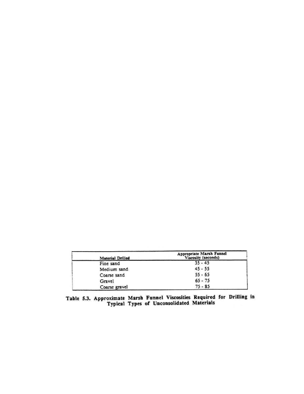
the solids and the base fluid (hydration potential). In general, high viscosity drilling fluids are required to
lift coarse sand or gravel, whereas lower viscosity drilling fluids are adequate to lift fine sand and silt.
Page 84 of 360
Viscosity of a fluid can be measured by a viscometer or a Marsh funnel. A certain volume of drilling
fluid is allowed to drain from a special funnel into a cup; the flow time is recorded and calibrated against
the time required for an equal volume of water to drain from the funnel (about 26 seconds at 70°F;).
These values, called apparent viscosities, are approximate and are good only in a relative sense.
Viscosities should be no higher than necessary to efficiently lift cuttings to the surface and control fluid
losses. Although drilling conditions can vary greatly, a Marsh funnel viscosity of 35 to 40 seconds will
usually be satisfactory in fine sand formations. If coarse sediment (gravel) is encountered, viscosities
must be substantially increased so that coarser particles do not have to be finely ground to be lifted by
the drilling fluid.
5.3.3.1. Viscosity of Drilling Fluids Made with Clay Additives
The viscous nature of drilling fluids made with clay additives originates from the small size of clay
particles (less than 4 microns) and their relatively large surface areas. Most clay particles have a platelike
structure; groups of these platelets are common. Clay particles generally swell when exposed to water
because the electrically unbalanced water molecules are strongly attracted to the plate surfaces and
thereby force the plates apart. This results in the clay particles occupying a larger space, which leads to a
more viscous fluid. Different types of clay have a wide range of hydration potential. Clays that hydrate
effectively are preferred because they produce a low-solids drilling fluid with high viscosity. Clays such
as montmorillonite, kaolinite, and illite are the primary clays used for fresh-water drilling fluids,
although montmorillonite is the only clay of these three that is available commercially. The
viscosity-building characteristics of sodium montmorillonite are the greatest of any clays, because the
sheets of atoms making up the flat clay particles are much thinner and come apart more easily in water
than those of other clays. Clays used for drilling fluids are rated by their yield, which is defined as the
number of 42-gallon barrels of drilling fluid with an apparent viscosity of 15 centipoise produced by
2,000 lb of clay. Water at 68°F has a viscosity of 1.005 centipoise. The term “bentonite" is used as a
commercial name for clays blat are predominancy sodium montmorillonite. Wyoming bentonite is most
common drilling fluid additive used in the water well industry.
5.3.3.2. Viscosity of Drilling Fluids Made with Polymeric Additives
In recent years, the use of natural and synthetic polymeric colloids in drilling fluids has increased. A
polymer is a long-chained chemical compound consisting of many small molecular units (monomers)
combined together. Polymers can be either natural or synthetic, usually have a high molecular weight,
and form chains of monomers several thousand units long. When the chains become tangled, they tend to
Page 85 of 360
make a strong film. Polymers may be used as the primary additive or to beneficiate bentonitic drilling
fluids. They are described as low-solids or clay-free drilling fluid additives. Polymers are used to
increase drilling rates and drilling fluid yields, thereby decreasing operational costs.
The unusual physical and chemical properties of polymers offer several specific advantages: (1) holes
can be drilled with reduced bottom-hole pressures; (2) fluid loss can be controlled without the buildup of
a thick filter cake; (3) torque and friction losses are reduced; (4) cores and other samples are not masked
by the drilling fluid additive; (5) some polymers are compatible with brackish water or even brine; and
(6) cuttings settle rapidly at the surface so it is possible to circulate clean, lightweight, nonabrasive
fluids. Polymers also increase the effectiveness of some well-logging methods because of their high
resistivity.
5.3.4. Gel Strength of Drilling Fluids Made with Clay Additives
Gel strength is a measure of a drilling fluid's ability to support suspended particles when the fluid is at
rest. The gel structure of a drilling fluid made with clay additives is produced when the clay platelets
align themselves to join together positive and negative charges. The positively charged edge of a plate
aligns itself with the negatively charged flat surface of an adjacent plate. This structure gives the liquid a
plastic form with strength properties caned gel strength. If enough stress (agitation) is applied to the
drilling fluid by the pump, the gel will break down.
When a drilling fluid is at rest, however, some of the clay plates will orient themselves to balance the
electrical charges on the edges and flat surfaces of the plates. This process is called flocculation and is
the main cause of gel strength.
A drilling fluid generally exhibits more than one physical condition. The four common drilling fluid
states are aggregated-flocculated, aggregated-deflocculated, dispersed-flocculated, and
dispersed-deflocculated. The greatest gel strength occurs when the drilling fluid is in a dispersed-
flocculated state. For example, if the driller has done a thorough job of mixing the clay additives so the
platelets are dispersed, and the drilling fluid is then allowed to remain at rest, the drilling fluid will
assume a dispersed-flocculated state leading to a high gel strength and a uniform solids content.
If a drilling fluid with clay additives is left standing in a borehole or mud pit for some time, it gains in
gel strength as increasing numbers of clay plates align themselves. This quality is called thixotropy and
is a characteristic of rainy paints and varnishes. After the drilling fluid has been allowed to remain at rest
for some time, excessively high gel strengths may demand so much pump pressure to resume circulation
that the drilling fluid may be forced into fractured or weak formations.
Adding bentonite win increase gel strength, but care must be taken not to add so much that settlement of
cuttings at the surface is retarded. Just enough bentonite should be used to lift the cuttings and support
any weighting material at the desired pumping rate.
Water chemistry also affects the gel strength of a drilling fluid made with clay additives. The use of soft
water helps clay additives attain a well flocculated condition, whereas in hard water groups of clay
platelets tend to remain together and gel strengths are somewhat less.
5.3.5. Gel Strength of Drilling Fluids Made with Polymeric Additives
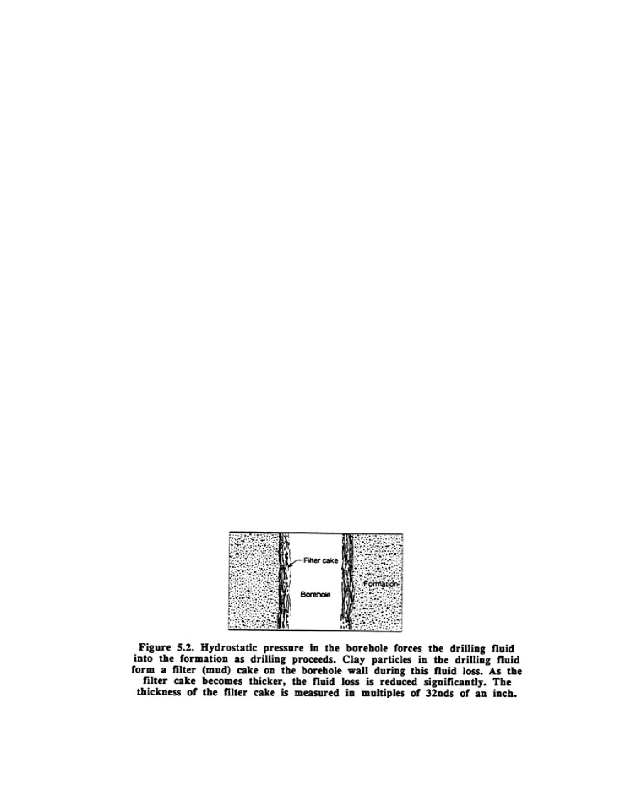
Page 86 of 360
Natural and synthetic polymeric drilling fluids have virtually no gel strength. This lack of gel strength
assures that cuttings removal is exceptionally good at the surface, wear on the mud pump by abrasive
material is minimized, and pumping pressures are minimized during normal circulation and resumption
of circulation. The drilling contractor should, however, clear the borehole of cuttings before circulation
is stopped, to prevent them from accumulating around the drill bit.
5.3.6. Filtration
Another of the principal requirements for a drilling fluid is to prevent fluid loss by forming a filter cake
or low-permeability film on the porous face of the borehole. The sealing property depends on the amount
and nature of the colloidal materials in the drilling fluid. The filter cake produced by clays and the thin
film created by polymeric colloids are physically dissimilar, because the size and shape of the particles
differ and their ability to hydrate is significantly different. Colloidal particles and suspended cuttings
entrained during drilling are important components of the total solids that create a filter cake or film.
Thus, the filtration properties of all drilling fluids are, in part, supplied by materials derived from the
borehole.
When drilling begins, hydrostatic pressure in the borehole causes the drilling fluid to flow into porous
formations. For drilling fluids made with clay additives, the fluid and some clay particles initially enter
the formation unhindered; but as the suspended solids and cuttings continue to close off the pores, clay
particles filter out and form a cake on the borehole wall. As the remaining pores around the borehole
become clogged with particles, progressively smaller volumes of water can pass into the formation
(Figure 5.2). In time, a filter cake effectively limits water flow through the borehole wall except in
highly permeable zones where lost circulation is apt to occur.
During drilling, the thickness of the clay filter cake will vary according to the rate of erosion caused by
the rotation of the tools and by the uphole velocity of the drilling fluid. In addition, thicker filter cakes
will form in formations that have higher hydraulic conductivity. When circulation stops, the filter cake
will continue to build up on the wall of the borehole.
The nature of this filter cake or film and the way it farms are quite different when drilling fluids are
prepared with polymers. Guar gum is a polysaccharide that provides natural fluid-loss control. This
property is derived from both the soluble guar gum particles (sols) dispersed in the drilling fluid and the
insoluble cell-wall residue (insols) of the gum.
Page 87 of 360
Although a filter cake is required during drilling, any residual clays on the borehole wall and in the
aquifer after the well has been completed are highly detrimental to the well's productivity. Well
development procedures should be conducted as soon as possible after a well has been drilled.
Otherwise, complete drilling fluid removal may become impossible, especially if clay additives are used.
Filter cake removal during development can be accomplished primarily by mechanical means, even
though the addition of polyphosphates can be helpful.
5.3.7. Design of Mud Pits
Drilling fluid is usually mixed adjacent to the drilling rig in either portable or excavated pits. The
capacity of portable pits for direct rotary rigs ranges from 200 to 10,000 gal. Large pits, 20,000 to 80,000
gal, are suitable for reverse circulation drilling. Although a mud pit is excavated prior to drilling with
reverse circulation, a premixed drilling fluid is usually not prepared because only clean water is
generally used. The size of the mud pit is dictated by the volume of drilling fluid contained in the
finished borehole and the need for a reserve volume, which varies according to the particular rotary
system used. Usually the volume of the pit is one and a half to three times the volume of the finished
hole. For reverse rotary drilling, where drilling fluid losses are usually high, the volume of the pit is
generally three times the volume of the finished borehole.
The design of the mud pit should take several factors into consideration (Figure 5.3). The principal
objectives of the pit are to store an adequate volume of drilling fluid and to act as an effective settling
basin for suspended cuttings. For efficient removal of the suspended cuttings, the pit should be
constructed in two sections—the settlement part and the suction part.
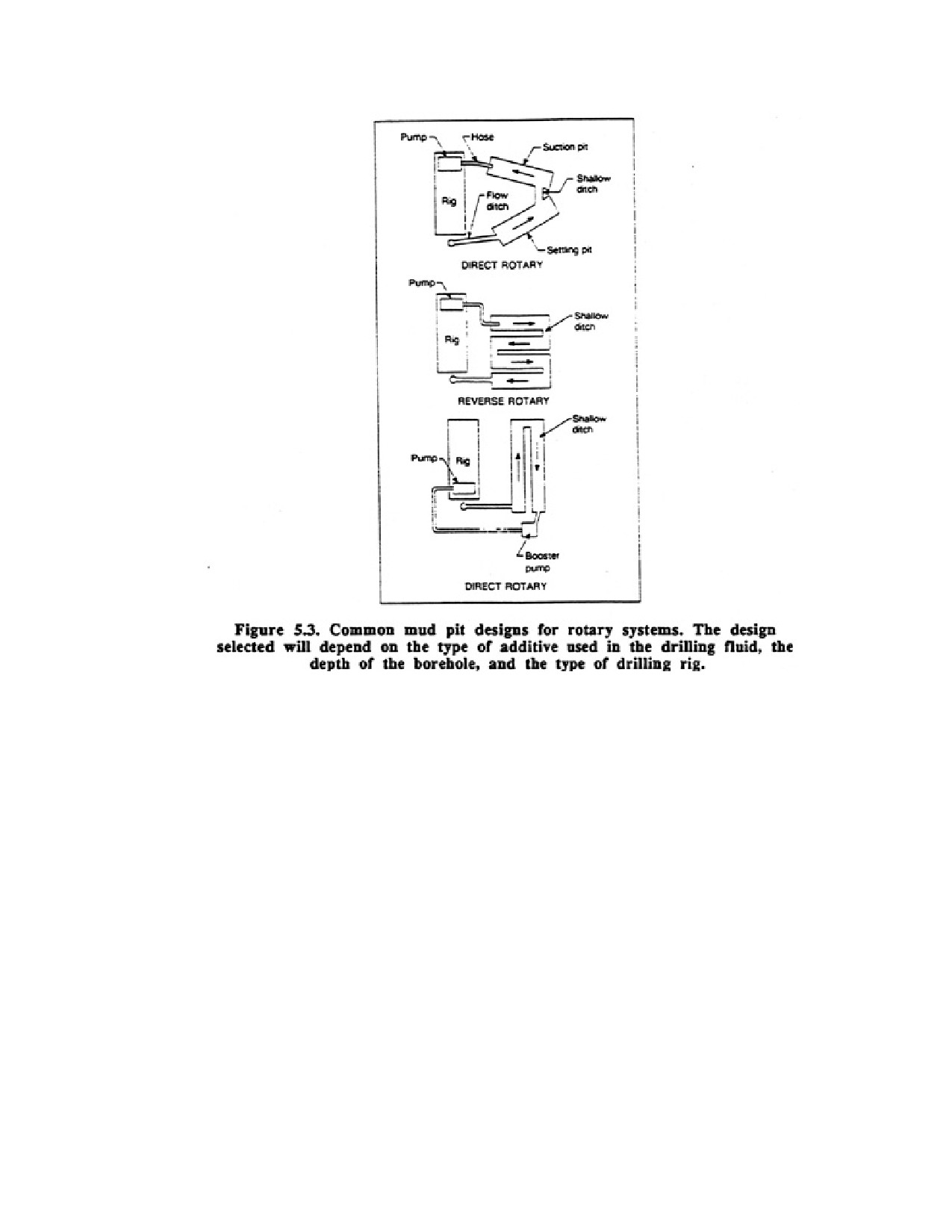
Page 88 of 360
Many drillers, however, use single-reservoir pits that serve both of these functions. The velocity of the
drilling fluid as it moves through the mud pit during the storage internal must be as low as possible. This
can be achieved by changing the direction of flow as the drilling fluid moves through the pits, as well as
by deepening part of the pit or by using baffles and overflows. Deeper, rather than wider, trenches are
more satisfactory in reducing drilling fluid velocity. When a single pit is used, some drillers will slope
the bottom of the pit downward toward the pump suction point to slow the velocity and create a place for
the cuttings to settle. The suction hose must be mounted above the bottom of the pit. The bottom of an
excavated mud pit should be sealed with a plastic film or a compacted layer of clay.
5.4. AIR DRILLING
Many water wells are now drilled with air because of the relative simplicity and effectiveness of air
systems and the increasing number of rotary rigs equipped with air compressors. The earliest attempts to
use air as a circulating medium during the 1950's showed that significant increases in penetration rates
and bit life could be obtained. Air drilling is now recognized as a primary method to reduce drilling time
and therefore the cost of a well. The mechanics of air drilling are more difficult to understand than
typical water-based systems because the drilling fluid is compressible and often contains water, an
incompressible fluid, and other special additives.
To drill with air, the drilling rig must have access to an adequately sized compressor and a water pump
that can inject up to 10 gal of water and chemicals into the air stream. On some rigs, a special pump is
used to inject surfactants into water before the water is injected into the drill rods.
Page 89 of 360
The compressor is usually the key to successful air drilling because insufficient air volume and pressure
are the principal problems in air drilling.
Compressors used on water well rigs are either the piston (reciprocating) type or the helical-screw type.
Piston-type compressors are efficient at compressions up to 30:1 and possess high pressure capacity. On
the other hand, screw-type compressors typically have somewhat lower pressure capacity than piston
compressors, but are positive displacement and consequently produce a constant air volume.
Compressors are rated to deliver a given air volume at a certain operating pressure. In practice, air
delivery at a rated pressure means that a specific number of cubic feet of air at atmospheric pressure can
be compressed and delivered to the rig at that pressure every minute. Once the air has been compressed
to the delivery pressure, it no longer has the original free-air volume. The compressor rating is valid at
sea level (maximum air density) at an air temperature of 60°F. The rating is usually designated at a
compressor speed of 1,800 to 2,100 rpm. As atmospheric pressure decreases or temperature increases
above 60°F, less standard air volume is compressed at a given rpm.
Both piston compressors and screw-type compressors can have one or more stages (compression units).
Air volume or pressure demands often require that more than one compressor be used. Compressors
connected in series will increase the pressure in an air system, whereas a parallel arrangement will
increase the volume. Although the output pressure can be regulated on a screw compressor, it should
never be reduced when a down-the-hole air hammer is being used in air drilling. The pressure may be
adjusted downward for well development work, however, so the screen is not damaged. This is
especially important if the pressure is greater than 300 psi.
The standard compressors used on water well rigs have increased in air-volume capacity and pressure
capability in order to drill deep, large-diameter holes, to achieve high penetration rates, and to maximize
drilling rates with down-the-hole hammers. A good method to verify that enough air is available to
remove the cuttings efficiently in dry-air drilling is to check the time needed for the air to clean up after
drilling ceases. The time required to clean the cuttings should not greatly exceed 6 to 7 seconds per 100
It of borehole. More air is needed as boreholes deepen, in addition, 30 to 40 percent more air is required
when drilling with air-mist systems.
For down-the-hole air hammers, higher pressures translate into increased penetration rates when drilling
with dry air because the hammer action is more rapid. Higher available pressure can also be used to
overcome static heads following a temporary cessation of drilling.
Several options exist when air is used as the drilling fluid:
1. Air alone (dry air)
2. Air mist—a. Air plus a small volume of water b. Air, small volume of water, plus a small amount of
surfactant
3. Air-foam--- a. Stable foam—air plus surfactant b. Stiff foam—air, surfactant, plus high-
molecular-weight polymer or bentonite
4. Aerated mud---water-based drilling fluid plus air
Page 90 of 360
Decisions on which of these systems to use depend on the volume of water entering the borehole, the
penetration rate, the volume of air available, the nature of die formations being drilled, and
environmental conditions affecting the drilling process.
5.4.1. Dry-Air Systems
The simplest air drilling system involves using only dry air as the drilling fluid. Optimum drilling rates
are achieved by using dry air because the column of air puts minimum pressure on the bottom of the
borehole. As removal of the rock overburden proceeds, the cuttings become progressively easier to chip
off because the overlying weight of the rock has been removed. Water well drillers will ordinarily begin
all boreholes with only dry air, but dust problems and influx water will usually create the need to alter
the dry-air system.
Compared with water-based drilling fluids, dry-air systems offer the following advantages:
1. Higher penetration rates in dense, consolidated rock
2. Reduced bit wear
3. High solids-carrying capacity
4. Reduced formation damage and self-induced fluid loss
5. Low water requirements
6. Minimized swelling problems associated with water-sensitive clays
Air drilling is extremely effective in drilling hard, stable formations such as igneous and metamorphic
rocks, and tough, dense sedimentary rocks such as dolomite where penetration rates are often
exceptional. Because air has the lowest density of any drilling fluid and therefore places minimum
downward pressure on the formation being drilled, cuttings chip off readily with either a roller or a
down-the-hole air hammer bit. Boreholes are kept clean by the high annular fluid velocity, which ranges
from 3,000 to 5,000 ft/min for dry air. Uphole velocities to 7000 ft/min may be desirable for deep holes
drilled at high penetration rates. In general, the lifting capacity of air is proportional to its density and to
the square of its annular velocity. Thus, the driller adjusts air volume and pressure at the surface to
compensate for the weight of the cuttings and for increases in density with depth in order to maintain the
required annular velocity.
Air drilling is particularly advantageous where drill and drive techniques are used for unconsolidated
formations such as glacial outwash and alluvial deposits or for semiconsolidated formations such as
bouldery tills. In this type of drilling, hole stability is not a major problem and the many benefits of
drilling with air make this technique attractive.
Air is helpful in overcoming lost-circulation problems in highly fractured igneous and metamorphic rock
and in highly porous formations. Many drillers who use waterbased drilling fluid systems will change
immediately to an air or air-foam system if large crevices or cavities are encountered. However, lost-
circulation problems can occur when air systems are used to drill permeable sandstone. In this type of
formation, so much air is lost that uphole velocities may be insufficient to lift the cuttings. To overcome
this problem in sandstone, polymers and water are sometimes added to the air. The thin polymeric film
seals the formation pores so air loss is minimized.
Problems with air drilling, especially dry-air drilling, usually involve an insufficient air supply, resulting
in an annular velocity that is not high enough to carry the cuttings to the surface. For a given diameter,
hole depth is a primary factor affecting cuttings removal because air-volume requirements are directly
Page 91 of 360
related to depth. Erosion of the borehole walls can also create an increase in the demand for air that may
exceed the capacity of the compressor. On the other hand, too much air can be a problem because soft
spots in a borehole wall can be eroded, resulting in blowouts (borehole enlargement) which, in turn, can
lead to even higher air-volume demands.
Another drilling problem occurs when small amounts of water begin to enter the borehole during dry-air
drilling. Water mixes with the smallest rock cuttings to produce muds that can plug the formation and
limit the potential yield of the well. If enough mud is present to form rings, or collars, on the drill string
or borehole wall, air flow is restricted and the drill rods may stick in the borehole. When mud collars
form, restriction of the annulus causes excessive pressure build up below the collar, and fracturing of the
formation materials can occur. Fracturing and blowouts can be minimized if the rig is equipped with
compressors that can be controlled by a relief valve at the operator’s station. The driller can then take
immediate action when the pressure rises suddenly to reduce the chance for blowouts and fracturing in
loose formations.
5.4.2. Air-Mist Systems
Adding small amounts of water to air creates an air-mist system. Many drillers add water to the air
system to control dust and to help break down any mud collars forming on the drill muds. To help
increase the wetting action of the injected water, small amounts of surfactant may also be added to the
airstream. Air-volume requirements usually increase substantially when switching from dry air to air
misting, because greater downhole pressure prevents immediate expansion of the air as it leaves the bit.
Air-mist techniques can be used satisfactorily as long as only small volumes of influx water, 15 to 25
gpm, enter the borehole from the aquifer. When the volume of water entering the borehole increases, an
air-foam system must replace the mist system.
5.4.3. Air-Foam Systems
Ordinarily, foam is defined as a dispersion of air in water. In an air-foam drilling system, however, air is
the continuous phase and water is the dispersed or discontinuous phase. Thus, drilling foam is created
when a small volume of water and surfacing is injected into an airstream. Although some foam forms
naturally when water enters an airstream, the amount and stability of the foam is enhanced significantly
when a surfactant is added. The term "foam drilling" is associated with the introduction, into air, of a
surfactant mixed with water. Surfactants include anionic soaps, alkyl polyoxethylene nonionic
compounds, and cationic amine derivatives. All of these are available as commercial products.
The addition of a surfactant to an air-based drilling fluid has several advantages over the use of air alone.
These include:
1. Higher solids-carrying capacity
2. Ability to lift large volumes of water
3. Reduced air-volume requirements
4. Reduced erosion of poorly consolidated formations
5. Effective dust suppression
6. Increased borehole stability
Air-foam systems are not effective, however, when confined formations are intercepted, because the
downhole pressure is so low that the borehole may become unstable or so much water may enter the
borehole that the air-foam system cannot remove it.
Page 92 of 360
Foams are used primarily to enhance the rate of cuttings removal by preventing them from aggregating
so they can be lifted more easily to the surface. Foaming agents are also added to air when the airstream
can no longer lift the water entering the borehole. The required volume of surfactant will usually range
from 1 qt to 3 gal per hour, depending on the type of surfactant, the volume of water entering the
borehole, the diameter and depth of the borehole, and the quantity and size of the cuttings. The surfactant
concentration commonly varies from 0.25 to 2 percent of the injected water, but may be increased
significantly in deep, large diameter boreholes with large quantities of influx water.
5.4.4. Aerated Drilling Fluids
Air is sometimes injected into water-based drilling fluids to lighten the weight of the drilling fluid
column. This procedure is common in the Inverse system and for air-assist reverse-circulation rotary
drilling. The introduction of air increases the penetration rates 10 to 50 percent over conventional mud
drilling. In addition, fluid loss to highly permeable zones is often reduced or eliminated. One
disadvantage of aerating water-based drilling fluids is that it causes higher rates of drill-pipe corrosion.
5.4.5. Regulating the Air-Foam Drilling System
In most air-foam drilling operations, the contractor will have an intuitive feeling as to whether the
drilling fluid system is functioning properly, mainly on the basis of penetration rate. But just as in
water-based drilling fluid systems, adjustments of the physical characteristics of the drilling fluid should
be based on more than just intuition if maximum drilling efficiency is to be maintained. Because
conditions change as the drilling fluid circulates in the system, the required pressure, air volume, and
liquid-volume fraction (LVF) normally should be established for the most critical point—in the annulus
just above the bit. At this point, the LVF should be 2 to 5 percent; in no case should it be more than 15
percent.
Unfortunately, it is rarely possible to actually measure pressure or temperature conditions at many points
in the circulation system. Therefore, the driller must observe (usually at the discharge point) various
physical characteristics of the air-foam system when possible and learn to relate these characteristics to
drilling efficiency. The important visual observations or measurements which indicate when the
adjustments should be made are listed below.
1. Water volume, air volume, and pressure.
2. Foam pressure at the standpipe.
3. Percentage of surfactant and other foam stabilizers being injected.
4. Foam consistency at the surface:
a Visual assessment for consistency
b. Density
c. Percent LVF
d. Percent and size of solids
e. Volume
5. Regularity of returns at the surface.
6. Drill-string torque requirements.
As a general operating guide for an air-foam system, the driller should attempt to maintain foam
consistency once the rates of penetration and water removal are satisfactory. The ability to make the
correct adjustments to the system by visual observations and actual measurements will improve as the
Page 93 of 360
experience and skill of the contractor increases. When initiating an air-foam system, the driller will
generally observe the following:
1. Before the foam has become stable downhole, a steady rush of air will leave the discharge tee. If the
foam does not form, fluid (injection) volume should be increased or air volume decreased for a few
minutes.
2. When the proper foaming action begins downhole, a gentle puffing of air can be felt at the discharge
tee.
3. When foam returns begin, the foam should extrude steadily and have good stiffness.
4. Good foam-carrying capacity usually occurs when a gentle surging action is observed at the discharge
tee. If the foam is too stiff, this surging action will not occur. If the foam surges violently, too much air is
being pumped into the borehole.
5. As conditions change, the proper foam concentration, water injection rate, and air volume must be
maintained to achieve good penetration.
Common problems with foam drilling fluids are indicated by the physical condition of the foam at the
surface and by pressure buildup in the borehole.
In summary, specific suggestions for successful air-foam drilling include the following:
1. The greatest lifting capacity occurs when the LVF is about 2 percent, therefore, the LVF at the bottom
of the borehole should be as close to 2 percent as possible. If the LVF exceeds 25 percent, the lifting
capacity of the foam will be unsatisfactory.
2. The annular velocity at the bottom of the borehole should be at least 50 ft/min.
3. To calculate the correct volume of water to be injected for an LVF of 2 percent and an uphole velocity
of 100 ft/min, multiply the annular volume for 1 ft of borehole by 2. Another good rule of thumb is to
inject at a rate of 0.5 to 1 gpm per 1 in of borehole diameter.
4. For most shallow water wells, 50 to 500 cfm of air are needed at pressures of 100 to 350 psi.
5. A safety factor for calculated air volume is usually 25 percent
6. A temperature corrosion for air-volume changes may be necessary, but for most drilling operations the
temperature change is not sufficient to necessitate a correction.
5.5. DRILLING FLUID ADDITIVES
A proliferation of drilling fluid additives has occurred since 1940. For most water well drilling
operations, certain standard procedures are followed which depend on the particular type of drilling fluid
used. Specific ranges for viscosities, uphole velocities, and additive concentrations are well established
and represent the starting point for mixing most drilling fluids. However, unusual borehole structure or
groundwater chemistry may dictate a change from these initial drilling fluid conditions.
5.6. GUIDELINES FOR SOLVING_SPECIFIC_DRILLING FLUID PROBLEMS
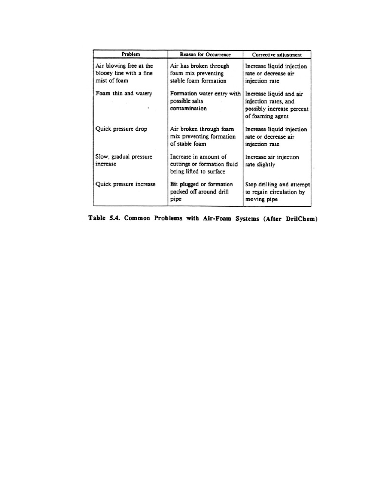
Page 94 of 360
The enormous variety of chemical and physical conditions that can exist in boreholes, and the large
number of commercial products available to remedy specific problems, preclude a simple prescription
for successful use of drilling fluids. Certain problems, however, occur regularly in typical geologic
formations when using ordinary additives. Swelling clays, for example, are a major problem when
drilling with rotary systems. The Corcoran Clay in the San Joaquin Valley of California, and the Laramie
Formation in the Denver Basin, are notable examples. As the clays hydrate and expand, the borehole is
partially or completely plugged, and occasionally the drill string may become stuck. The section below
contains recommendations for solving clay swelling and other common drilling fluid problems.
PROBLEM: Inadequate cuttings removal from borehole.
RECOMMENDED ACTION:
1. Clays and polymeric solids in water.
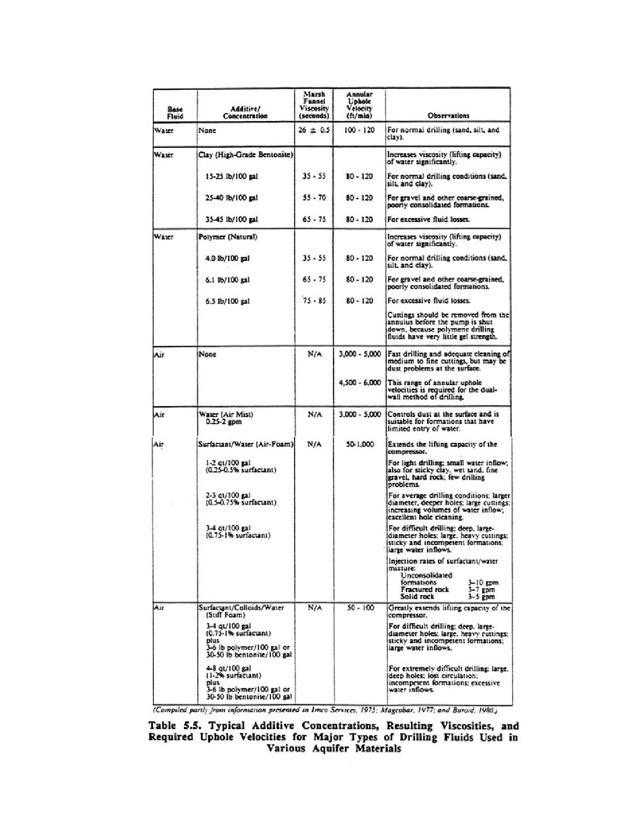
Page 95 of 360
Page 96 of 360
a. Increase uphole velocity of the drilling fluid
b. Increase viscosity of the drilling fluid by adding more colloidal material
c. Increase density of the drilling fluid by adding weighting material
d. Reduce penetration rate to limit cuttings load.
2. Air
a. Increase uphole velocity of fluid system by adding air or water
b. Add surfactant to produce foam or to increase concentration of surfactant
c. Decrease air injection rate if air is breaking through the foam mix and preventing
formation of stable foam
d. Decrease water content of the foam system
PROBLEM: The rate at which cuttings will drop out is too low because the inadvertent addition of
native clays during drilling has produced excessive viscosity in the drilling fluid
RECOMMENDED ACTION:
1. Add water to dilute the drilling fluid
2. Add commercial thinner to reduce the addictive forces between clay colloids
3. If using clay additives, convert to a polymeric system.
4. Separate the solids from a clay additive system with shale shakers and desanders connected in series,
or a shale shaker alone. Utilization of a desander or shale shaker may be unnecessary when a polymeric
system is being used.
5. Redesign or clean the pit system to increase rate of cuttings settlement.
PROBLEM: Gel strength becomes too great because of strong flocculation, high concentration of solids,
or contamination from evaporite deposits or cement. (Excessive gel-strength problems do not occur with
polymeric colloids.)
RECOMMENDED ACTION:
1. Add water to dilute the drilling fluid.
2. Add polyphosphate or commercial thinner to reduce electrical charges between clay colloids.
3. Use desander or shale shaker to remove solids from a clay additive system.
4. Lower the pH.
PROBLEM: Excessive fluid loss into the formation, causing thick filter cakes that can produce tight
places in the hole, development problems, formation (clay) sloughing, and misinterpretation of electric
or gamma-ray logs.
RECOMMENDED ACTION:
1. Increase viscosity by adding bentonite or polymeric colloids to any waterbased system.
2. Add commercial viscosifiers such as CMC or HEC.
3. Reduce density of the drilling fluid.
4. Prevent drastic changes in downhole pressures and maintain downhole pressures at a minimum.
Suggestions include:
a Raise and lower the drill string slowly.
b. Drill through any tight section; do not spud.
Page 97 of 360
c. Begin rotation of the drill pipe, and then start the pump at a low rate and gradually increase the rate.
d. Operate the pump at the lowest rate that will assure adequate cooling of the bit and removal of cuttings
from the bit face.
e. Prevent balling at the bit; do not drill soft formations so fast that the annulus becomes overloaded and
pressure builds up.
PROBLEM: Lost circulation in permeable formations, faulted and jointed rock, solution cavities in
dolomite and limestone, or fractures created by excessive borehole pressures in semiconsolidated or well
consolidated rock.
RECOMMENDED ACTION:
1. Reduce density of the drilling fluid system.
2. Switch from a clay additive drilling fluid system to an air-foam fluid, or add surfactant to a dry air
system.
3. Gel natural polymeric fluids at the point of fluid loss.
4. Use commercial sealing materials.
5. Drill remainder of the hole with a cable tool rig.
6. Case off, then resume rotary drilling.
7. Kill the borehole with clean sand to the point above lost circulation. Let the material stand in borehole
over night. Resume drilling, using low pump pressure.
8. Grout the lost-circulation zone and drill through the plug.
PROBLEM: Confined pressures in the formation.
RECOMMENDED ACTION:
1. Increase density by adding heavy mineral additives such as barite to defiling fluid systems made with
clay additives. To suspend barite, the minimum Marsh funnel viscosity must equal four times the final
(desired) drilling fluid weight (in lb/gal)
2. Increase density by adding a salt solution to polymeric drilling fluid systems
PROBLEM: Shale sloughing caused by hydration (swelling and dispersion), pore pressures, and
overburden pressure.
RECOMMENDED ACTION:
1. Use polymeric additive to isolate water from shale.
2. Maintain constant fluid pressures in the borehole.
3. Minimize uphole velocities.
4. Avoid pressure surges caused by raising or lowering drill rods rapidly.
5. Add 3 to 4 percent potassium chloride (KC1) to water-based systems.
6. Raise the pH of the drilling fluid to stiffen the clay.
PROBLEM: Presence of contaminants. Contaminants usually consist of cement, soluble salts, and gases
(hydrogen sulfide and carbon dioxide). Cement in the hole can cause polymeric drilling fluids to break
down, thereby inching fluid losses. Salts may cause drilling fluids with clay additives to separate into
liquid and solid fractions. Gases in water may affect the physical condition of the drilling fluid
Page 98 of 360
RECOMMENDED ACTION:
1. For cement problems:
a. Maintain the pH for natural polymeric drilling fluids at 7 or lower.
b. Add commercial chemicals such as sodium acid pyrophosphate to drilling fluids with clay additives
to restore original viscosity.
2. For salt problems:
a. Change the clay additive from montmorillonite toattapulgite.
b. Change to a natural polymeric drilling fluid additive
3. For gas problems:
a. Add a corrosion inhibitor.
PROBLEM: Drilling at air temperatures significantly below freezing, causing freezeup of the
recirculation system.
RECOMMENDED ACTION:
1. Add sodium chloride (NaCI) or calcium chloride (CaC12) to a natural polymeric drilling fluid See
Table 7.7 for the salt concentrations required to prevent freezing at specific temperatures. Salt must not
be added to a dotting fluid made with bentonite.
The problems enumerated above are not the only ones that can occur in water well drilling. Many other
problems result from inadequate pumping equipment, particle accumulation in the fluid system and at
the bottom of the borehole, slumping or expansion of active shales, and caving of resistant shelflike
rocks such as limestone and dolomite. Maintenance of borehole stability and careful drifting procedures
can help eliminate these problems, but once they occur, a solution must be determined rapidly for the
specific case.
5.7. CONCLUSIONS
This chapter has examined common drilling fluid systems and some typical problems that occur in
different geologic materials. Many specific problems associated with drilling can be resolved with the
help of the suppliers of drilling fluid products. Many times they can provide in-the-field help, and at least
one company sponsors regular training classes in drilling fluid systems. One point should be
remembered by the drilling contractor—whatever system you use, understand it well.
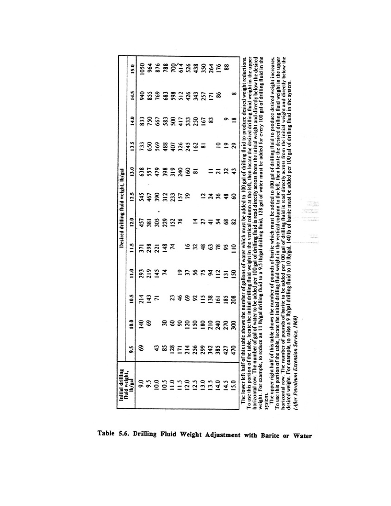
Page 99 of 360
Page 100 of 360
CHAPTER 6.
WELL SCREENS AND METHODS OF
SEDIMENT-SIZE ANALYSIS
A well screen is a filtering device that serves as the intake portion of wells constructed in
unconsolidated or semiconsolidated aquifers. A screen permits water to enter the well from
the saturated aquifer, prevents sediment from entering the well, and serves structurally to
support the unconsolidated aquifer material. The importance of a proper well screen cannot
be overemphasized when considering the hydraulic efficiency of a well.
Well screens are manufactured from a variety of materials. The value of a screen depends on
how effectively it contributes to the success of a well. Important screen criteria and functions
include:
1. Criteria
a. Large percentage of open area
b. Nonclogging slots
c. Resistant to corrosion
d. Sufficient column and collapse strength
2. Functions
a. Easily developed
b. Animal incrusting tendency
c. Low head loss through the screen
d. Control sand pumping in all types of aquifers
Maximizing each of these criteria in constructing screens is not always possible depending
on the actual screen design For example, the open area of slotted casing cannot exceed 11 to
12 percent or the column strength will be insufficient to support the overlying casing during
screen installation. However, open areas of 30 to 50 percent are common for continuous-slot
screens with no loss of column strength. In highly corrosive waters, the use of plastic is
desirable, but its relatively low strength makes its use impractical for deep wells.
The screen design must accommodate the varying physical and chemical characteristics of
ground water. Experience has shown that screens with the following characteristics provide
the best service in most geologic conditions and will satisfy the criteria listed above.
1. Slot openings should be continuous around the circumference of the screen, permitting
maximum accessibility to the aquifer so that efficient development is possible.
2. Slot openings should be spaced to provide maximum open area consistent with strength
requirements to take advantage of the aquifer hydraulic conductivity.
3. Individual slot openings should be V-shaped and widen inward to reduce clogging of the
slots and sized to control sand pumping.
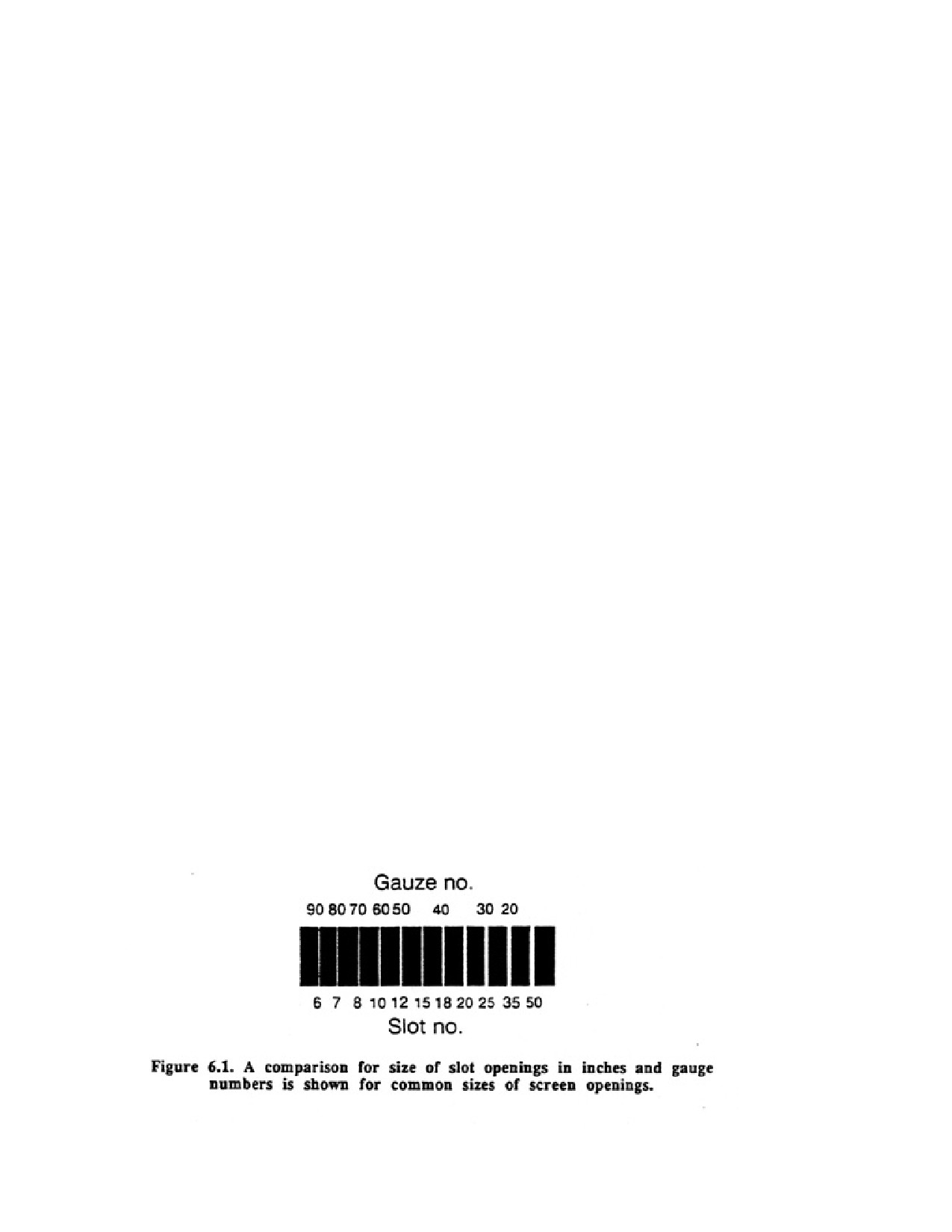
Page 101 of 360
4. Screen construction methods should permit the use of a wide variety of materials that are
compatible with differing groundwater environments to minimize corrosion and incrustation.
5. If constructed of metal, screens should be of single-metal construction to minimize
galvanic corrosion.
6. Screens must be sufficiently strong to withstand stresses normally encountered during and
after installation.
6.1. Continuous-Slot Screen
The continuous-slot screen is widely used throughout the world and is the dominant screen
type used in the water well industry. It is made by winding cold-rolled wire, approximately
triangular in cross section, around a circular array of longitudinal rods. The wire is attached
to the rods by welding, producing rigid one-piece units having high strength characteristics at
minimum weights. Welded screens are commonly fabricated from Type 304 and Type 316
stainless steel, monel, galvanic or ungalvanized low carbon steel, and thermoplastic
materials, mainly PVC and ABS or alloys of these materials.
Slot openings for continuous-slot screens are manufactured by spacing successive turns of
the outer wire to produce the desired slot size. These screens are typically fabricated in slot
sizes ranging from 0.006 to 0.250 in. Width of the openings can be held to close tolerances in
the all welded manufacturing method; allowable variations from the designated (ordered) slot
size generally range from 0.001 to 0.002 in, depending on the screen material and screen
size. Most high-quality screen manufacturers are concerned with slot variation because sand
pumping problems may occur if too many slots are significantly oversized slot control
quality is usually checked by comparing the designated size versus the average finished size.
All slots should be clean and free of burrs and cuttings.
Slot openings have been designated by numbers which correspond to the width of the
openings in thousandths of an inch A No. 10 slot, for example, is an opening of 0.010 in. Slot
size may also be expressed in metric units; for example, 0.010 in equals 0.25 rain. For
sm~l-diameter screens covered with wire mesh, the number of openings in the mesh per inch
me designated by gauze numbers. The size relationship of slot number and gauze number is
shown in Figure 6.1.
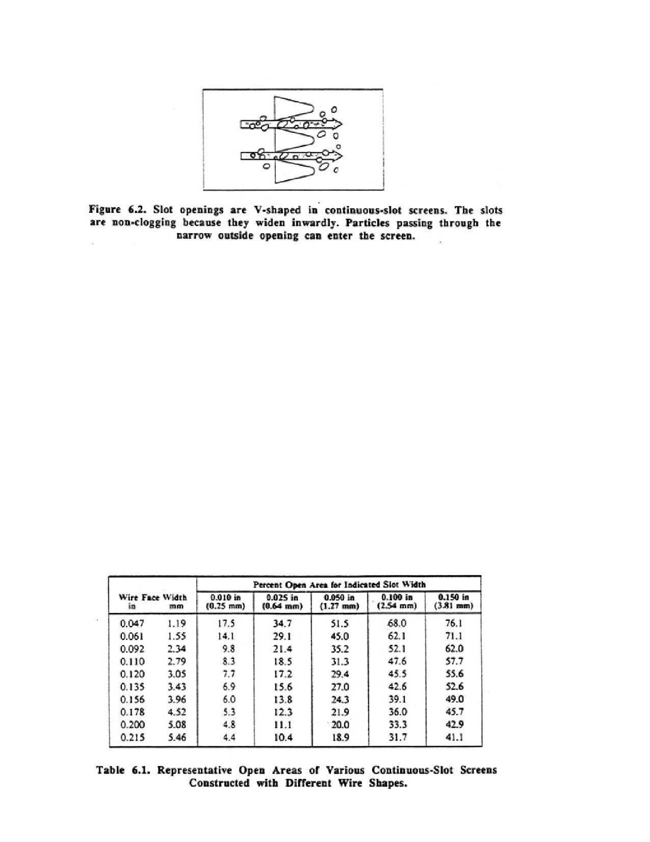
Page 102 of 360
For continuous-slot screens, individual slot spacing can be varied during fabrication. In fact,
a single section of screen may be made with many different slot sizes if geologic conditions
require these variations. In this way, maximum use of the hydraulic conductivity of each
stratum is possible.
Each slot opening between adjacent wires is V-shaped, resulting from the special shape of
the wire used to form the screen surface. The V-shaped openings, designed to be
nonclogging, are narrowest at the outer face and widen inwardly; they allow only two point
contact by any sand grains with a diameter larger than the slot size. Thus, oversized particles
are retained outside the screen and cannot close off the openings. Any sand grain that will
pass through the narrow outer part of the V-shaped opening enters the screen without
wedging in the slot. In screens with cut slots without V-shaped design, entering particles
often turn or twist sideways and, once lodged in the slots, the available intake area of the
screen is considerably reduced, causing either lower yield or greater drawdown (Figure 6.2).
Continuous-slot screens provide more intake area per unit area of screen surface than any
other type. For any given slot size, this type of screen has maximum open area Table 6.1
gives representative open areas of venous continuous-slot screens with differing outer wire
sizes (face widths) and slot sizes. Note that as the wire face width increases for a given slot
size, the open area decreases. However, larger wires increase the collapse strength of the
screen for any given diameter.