NATIONAL DRILLING ASSOCIATION DRILLER’S MANUAL (2005) - page 4
Page 153 of 360
11.1.7. DEEP-WELL TURBINE PUMPS
The centrifugal pump was designed originally as a suction-lift pump, although it was soon
adapted for water wells where suction lift was not possible by extending a shaft extension
from the aboveground driving unit to the impeller assembly. Today this pump is known as
the deep-well turbine pump.
11.1.8. VERTICAL TURBINE PUMPS
The pumping assembly of a vertical turbine pump consists of one or more impellers housed
in a single- or multi-stage unit called a bowl assembly. Each stage provides a certain amount
of lift; a sufficient number of stages (bowl assemblies) are assembled to meet the head
requirements of the system. When designing a pump system, the number of stages needed are
proportional to the head and horsepower requirements, whereas the discharge rate and
efficiency remain constant. The impellers are suspended on a vertical line shaft (drive shaft)
that is housed within the pump column which conducts the water to the surface. The size of
the outer column is selected on the basis of the pumping rate.
Individual sections of the pump column are generally 10 or 20 ft in length. The overall length
of column is determined by the pumping water level.
11.1.9. SUBMERSIBLE PUMP
Submersible pumps have bowl assemblies that are the same as those of vertical turbine
pumps. The motor, however, is submerged and is directly connected to and located just
beneath the bowl assembly. Water enters through an intake screen between the motor and
bowl assembly, passes through the stages, and is discharged directly through the pump
column to the surface.
Submersible motors are extremely compact and generally do not withstand overheating and
fluctuations in voltage. They are cooled by water passing by the motor casing and into the
intake of the pump, so a free flow of water must be maintained. Overheating may occur if the
well has cascading water or if the pump intake is set into a sump (casing below the screen).
Submersible pumps have several advantages:
1. The motor is directly coupled to the impellers.
2. It is easily cooled because of complete submersion.
3. Ground surface noise is eliminated.
4. The pump can be mounted in casings that are not entirely straight.
5. A pump house is not necessary if a pitless adaptor (underground discharge) is used.
Disadvantages of submersible pumps are:
1. Electrical problems caused by submerged cables and splicing of cables to the motor.
Page 154 of 360
2. Overall efficiency is generally lower.
3. They cannot tolerate sand pumping (will sand lock).
4. Motor is less accessible for repairs.
5. They cannot tolerate voltage fluctuations without proper protection.
11.1.10. JET PUMPS
Jet pumps are used in many domestic wells and are a combination of a centrifugal pump and
a nozzle-venturi arrangement. Water discharges under pressure through a nozzle inserted in
the pipe conveying the water. The nozzle is shaped so that it smoothly, but rather abruptly,
reduces the area through which the flow must pass, thus increasing the velocity of flow. In
accordance with the Bernoulli law, the water pressure in a pipe decreases in direct relation to
any increase in the flow velocity, and vice versa. That is, if the velocity increases at any point
because of a reduction in area, as would occur near the nozzle, the pressure decreases
proportionately at that point.
If the discharge velocity at the nozzle is great enough, the pressure at the nozzle will be
lowered sufficiently to draw water into the venturi assembly through an opening at this point,
and this water is added to the total volume of water flowing beyond the nozzle. The gradual
enlargement in the venturi tube to the full diameter of the pipe reduces the velocity with a
minimum of turbulence, and pressure in the pipe is recovered, minus the head loss caused by
Fiction. The prime mover in a jet pump is a centrifugal pump, which produces the flow to the
nozzle and maintains the combined flow through the intake pipe beyond this point. This
combined flow is composed of the recirculating water and the water picked up at the nozzle
from the well. The additional increment of water obtained from the well continues past the
control valve and goes into use or storage, while the volume required for producing the flow
is recirculated though the pressure line.
Jet pumps are inefficient when compared with ordinary centrifugal pumps, but this is not
necessarily objectionable in domestic installations, because of other favorable features, such
as:
1. Adaptable to small wells, down to 2-in inside diameter in deep-lift installations.
2. All moving parts are accessible at the ground surface.
3. Simple design combined with relatively low equipment and maintenance costs.
4. Capable of being installed with the moving parts offset from the well.
11.1.1 1. Priming Centrifugal Pumps
Priming is necessary to expel air from centrifugal pumps. Many devices and procedures are
used to obtain and maintain a primed condition in centrifugal pumps; the literature describing
them is fairly extensive. In general, however, all involve one or a combination of the
following: (1) a foot valve to hold water in the pump, (2) a means for venting to dispose of
entrained air, (3) an auxiliary pumping device to partially fill the centrifugal pump and intake
Page 155 of 360
line with water, (4) connection to an outside source of water under pressure for filling the
pump, and (5) use of self-priming construction. Self-pumping construction retains water for
priming in an auxiliary chamber which is integrated into the pump structure in such a way
that entrained air is exhausted as the pump circulates the priming water.
11.2. POSITIVE DISPLACEMENT PUMPS
Positive displacement pumps discharge the same volume of water regardless of the head
against which they operate, although in practice this is not quite true, because some water
slips past operating parts. This type of pump must be powered to meet maximum load based
on its discharge capacity and the greatest head under which it will operate. When used in a
water system, the rate of discharge is essentially the same at both low and high pressure, but
the input power varies in direct proportion to the pressure.
There are many designs of positive displacement pumps, but the types used most are:
1. Rotary pumps
2. Peristaltic pumps
3. Piston (reciprocating) pumps
11.2.1. Rotary Pumps
The rotary pump is widely used because there are many design modifications for special
applications. Most applications are of the suction-intake type, except when the pump is used
for booster purposes in conjunction with another pump to increase the pressure or to pump
hot water or other liquids having high vapor pressure; in this case, the pump operates under
positive intake pressure. Common designs use cogs or gears, and rigid vanes or flexible
vanes; none of these pumps require valves.
The original rotary pump was designed using gears, and is simple in principle and
construction. It consists of a plain housing with inlet and outlet ports, and openings for shafts
which carry the driver gear and a driven or idler gear. The gears are fitted closely in the
housing, and mesh with minimum clearance. When rotated, the gears squeaks the water from
between the teeth as they mesh together, bringing in a replacement supply of water along the
outer surface of the housing at the inlet side of the moving teeth of the gears.
A typical rigid-vane rotary pump has a series of dividers or vanes fitted into a slotted rotor.
When rotated, these vanes move radially to conform to the contour of the pump housing,
which is eccentric in comparison with the rotor, so that the water is pushed from the pump in
a continuous flow ahead of the vanes. Water moves into the housing behind the vanes
because a partial vacuum is created. A flexible-vane rotary pump has blades that bend to
provide the change in displacement volume which forces the water along its path.
11.2.2. Piston Pumps
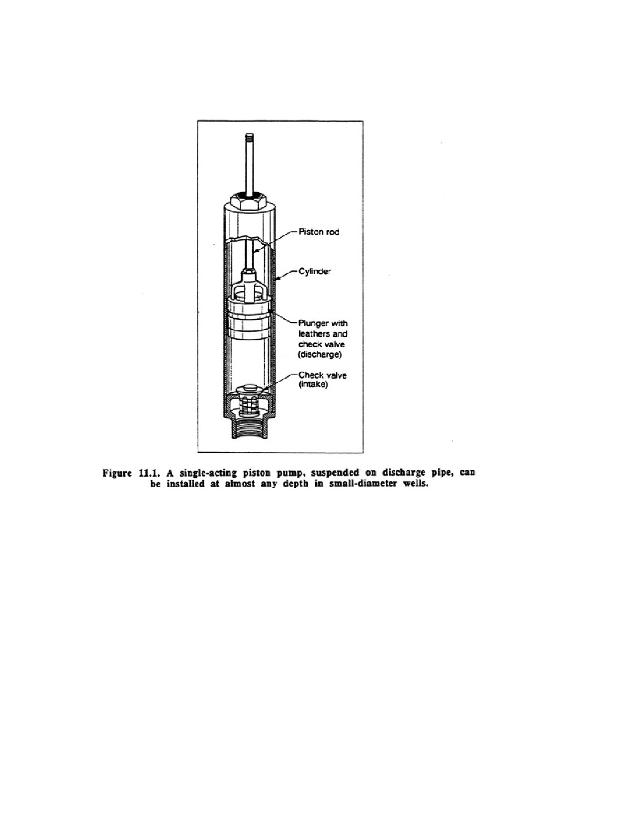
The simplest arrangement for a piston pump is the single-action pump shown schematically
in Figure 11.1. When the piston is drawn upward, the check valve in the piston is closed by
gravity and the water pressure above it. A lowering of pressure is therefore produced below
Page 156 of 360
the moving piston. Water flows through the intake valve into the pump cylinder as a result of
the pressure differential caused by the stroke of the piston.
As the piston moves downward, the intake valve closes when the pressure above it exceeds
the pressure below it, and the discharge valve opens when the pressure below it exceeds that
above it. Thus, water trapped in the cylinder during the downstroke of the piston is forced
upward into the discharge pipe on the next upstroke.
Because water is virtually incompressible, the piston moves the same volume of water at
each stroke, regardless of pressure, less any water that slips past the piston and valves. Piston
pumps must be powered to meet the maximum pressure application, and protection against
breakage must be provided by some device, such as a pressure-relief valve, in case the
pressure switch or other control mechanic fails.
The basic principles just described apply to all piston pumps; however, there are many design
modifications that adapt these pumps to specific uses. Double-action pumps, for example, are
constructed with piston and valves arranged so that water is pumped on both inward and
outward movement of the piston. These are most commonly suction-lift pumps, but are also
available for pressure-intake installations in wells. Duplex and triplex pumps consist of two
or three pistons, respectively, and are designed to pump a continuous stream with minimum
pulsation, often against high pressure. These pumps are often utilized for pumping drilling
fluid and grout.
Page 157 of 360
11.2.3. Priming Positive Displacement Pumps
Positive displacement pumps must be primed only to the extent necessary to stop leakage
past pistons, valves, or other working parts. They have the capability to move and compress
most fluids, including air, so that water (or another liquid) can be drawn into the pump
without priming.
11.3. PUMPS USED TO CIRCULATE DRILLING FLUID
Two basic types of pumps are used to circulate drilling fluid—reciprocating and centrifugal.
The reciprocating pump can be either single or double acting. Either of these designs can be
arranged in parallel by operating the pistons from a common crankshaft. They are then
referred to as simplex (1 cylinder), duplex (2 cylinders), and triplex (3 cylinders) pumps.
Additional pumps can be added if more volume must be moved.
Optimum operating conditions for reciprocating mud pumps are assured if:
1. The suction piping is as short as possible.
2. The diameter of the suction line is large enough so the fluid velocity is less than 3 ft/sec.
3. An intake strainer with two to four times the intake area of the suction hose is installed at
the end of the suction line.
4. The diameter of the discharge pipe is large enough so that the fluid velocity is less than 5
ft/sec.
5. The pump operates under proper net positive suction head conditions.
6. A surge suppressor is installed in the suction line as close to the pump as possible.
7. The pump is selected for a higher discharge than the expected demand.
8. Priming time does not exceed 30 seconds in order to minimize friction damage to the
plunger.
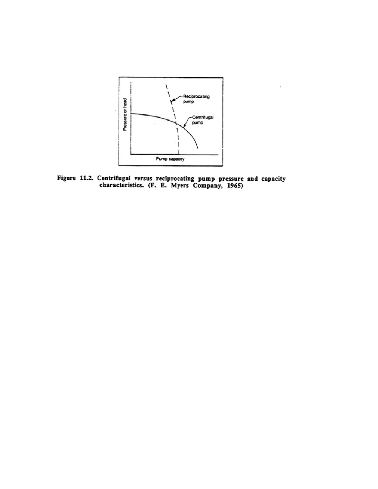
The operation of a centrifugal pump is described earlier in this chapter. When used for mud
pumps, they are designated by the size of the discharge and suction lines and the size and
rotation direction of the impeller. Unlike reciprocating designs, the rate of fluid delivery for a
centrifugal pump is variable depending on the pressure in the borehole. At maximum
discharge, the pressure head is usually about two-thirds the pressure obtainable at zero fluid
delivery. The actual drilling fluid discharge is a function of the rotation speed, fluid
efficiency, and the available power, as well as the downhole pressure. A centrifugal pump is
most suitable for low-pressure, high-volume situations, whereas reciprocating pumps are
ideal for high-pressure, low-volume applications. The basic difference in the operational
characteristics of the two mud pump types is illustrated in Figure 11.2.
11.4. AIR-LIFT PUMPING
Water can be pumped from a well by releasing compressed air into a discharge pipe (air line)
lowered into the well. Air bubbles mix with the water and reduce the specific gravity of the
water column sufficiently to lift it to the surface. Because air-lift pumping is inefficient in
comparison with other pumping methods, and because of the rather cumbersome and
expensive equipment required, this method of pumping is rarely used as a permanent
pumping system. In those instances where it is used, there is likely to be some special reason,
Page 158 of 360
such as the need for aeration to remove an objectionable gas, or the occurrence of a highly
corrosive or abrasive water that is destructive to pump parts. Air-lift pumping is used lather
extensively in the preliminary testing and development of wells.
11.5. PUMP SELECTION
Basic pump design, anticipated pumping conditions, and specific installation procedures are
factors that must be considered in choosing a pump for a water well. Pump engineers must
outline the general opening conditions for the pump before a specific type is selected. Design
parameters include:
1. Well diameter
2. Desired yield
3. Total dynamic head
a. Pumping water level (shallow- or deep-well conditions)
b. Above-ground head
c. All friction losses in column, pipe, fittings, etc.
4. Horsepower requirements
a. Brake horsepower
b. Horsepower required to offset shaft losses (vertical turbine)
c. Motor efficiency without thrust load
d. Losses caused by friction in the thrust bearing
e. Horsepower curve for varied discharge rates
5. Power source
a. rpm preferred or required
6. Pumping deviation - system-head-curve parameters
7. Sand-pumping potential
8. NPSH and specific speed, if required
9. Water quality
Page 159 of 360
10. Short- and long-term costs
a. Initial capital costs
b. Amortization of investment
c. Power costs
d. Supervision and maintenance
e. Cost of down time and standby equipment
After the most suitable type of pump has been determined from the available data, a specific
pump is selected that will best fit pumping requirements at the site.
11.6. PITLESS ADAPTORS
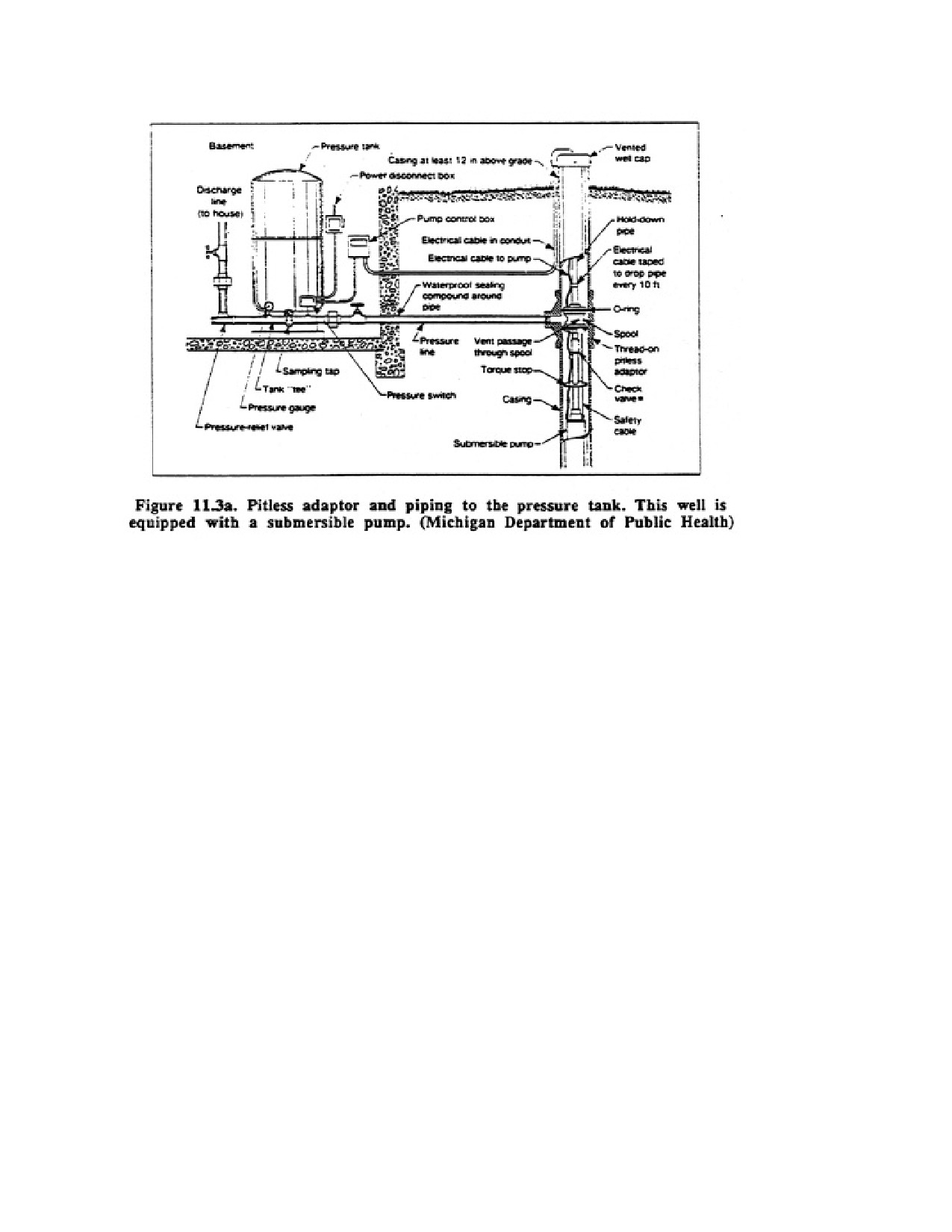
A sanitary underground discharge assembly, called a pitless adaptor, provides the most
practical solution to the sanitary completion of the upper part of a well when offset-pump
installations are specified.. This device, illustrated in Figures 11.3a and 11.3b, attaches
directly to the well casing and extends the casing above the ground surface. It provides a
watertight subsurface connection for buried pump discharge or suction lines. These pipes
must be buried below the frost line to prevent freezing.
Until the development of the pitless adaptor, installing pumps in pits below ground level was
common where frost protection for piping was required. Pump pits are always unsanitary,
and the pitless adaptor provides a practical means of eliminating them.
Besides their application in offset-pumping installations, pitless adaptors are equally useful
where the pump is installed in the well with the power drive mounted either on the well
casing or in the well (centrifugal and submersible pumps). The pump may be removed from
the well and replaced without disturbing the underground discharge pipe.
A removable device sealed inside the adaptor directs the water into the permanently
connected suction or pressure line. This device is suspended from the top of some pitless
adaptors and may be lifted out vertically, giving full-diameter access to the well for repair or
cleaning.
Page 160 of 360
CHAPTER 12.
GROUNDWATER MONITORING
TECHNIQUES
Approximately half the population of the United States is dependent upon groundwater for its
drinking water supplies. There is growing evidence that this resource, once considered
relatively pollution free, is being contaminated locally by municipal and industrial wastes.
Groundwater contamination occurs when soluble or insoluble substances are introduced into
the hydrogeologic environment as a result of man's activities. Groundwater pollution results
when the level of the contaminant concentration restricts the potential use of groundwater.
Groundwater contamination is so severe in certain localities that continued use of the water
could lead to serious health problems. Even though serious groundwater pollution problems
exist over rather small geographic areas, they often occur in areas having high population
densities. Irresponsible and ignorant waste-disposal practices of the past will continue to
affect groundwater quality for many years in spite of major detection and restoration efforts
now being pursued.
This chapter focuses on where and why groundwater contamination occurs, the methods used
to locate contaminant plumes, the design and construction of wells to monitor groundwater
quality, and the procedures used to clean up contaminated aquifers. Other aspects of
monitoring such as sampling procedures, equipment used to obtain samples from wells, and
procedures to assure quality of the samples are discussed only briefly because most of these
activities are performed by environmental consultants, not well contractors.
Page 161 of 360
Why has groundwater contamination occurred? In the past, people believed that nature
provided much better protection for groundwater quality than it actually does. Instances of
groundwater pollution such as the Love Canal near Niagara Falls, New York have caused
immediate and widespread concern for protection of the underground environment and a
realization that chemical contamination of this environment is both serious and widespread
(EOS, 1981). In St. Louis Park, Minnesota, for example, creosote contamination of soil and
underlying aquifers over a 50-year period has caused the closing of nearby municipal wells.
High concentrations of phenols, a potential carcinogen, have been found in these wells. In
another example, 100 water wells surrounding a landfill in Jackson Township, New Jersey
were closed because of organic chemical pollution (U.S. Environmental Protection Agency,
1980a). Although the landfill, which was constructed in a porous sand but never sealed
properly, was only licensed to accept sewage sludge and septic tank wastes, chemical
analyses of the groundwater in the vicinity of the landfill indicate high concentrations of
chloroform, benzene, methylene, chloride, trichloroethylene, ethylbenzene, and acetone.
Serious health problems have been reported by the well owners. On an even larger scale, 30
mi2 of the shallow aquifer underlying the Rocky Mountain Arsenal near Denver, Colorado
have become contaminated by chemical byproducts resulting from the manufacture of
pesticides.
In the United States alone, over 250,000 new chemicals are created each year. Of these, some
of the most troublesome are the widely used synthetic organic chemicals which are often
carcinogenic or toxic to man. Over a million organic chemicals already exist, and several
thousand new ones are developed each year. Sources of organic chemicals in groundwater
are leaking industrial lagoons, septic tanks, leaking gasoline storage tanks, agricultural
chemicals, and residues from paints and solvents.
After certain organic chemicals have entered an aquifer because of inadequate disposal
practices, Bushing of the aquifer or natural dilution of contaminants is so slow that total
cleansing of the aquifer may not occur except over extremely long periods of time—
hundreds or even thousands of years. Other organic chemicals have high mobility in the
subsurface environment and, once the source is cut off, the water quality returns to normal
within 10 to 20 years. The fate of organic compounds in groundwater and their rate of
movement through the system depends in part on their sorptive capacity, volatility, dilution,
biological activity, and chemical reactions.
Until recently, few people realized the extent of underground contamination or its adverse
impact on groundwater quality. Because groundwater contamination is usually difficult to
contain or control, governmental policies have been directed at its early detection, treatment,
and subsequent elimination. These policies are being expanded to eliminate waste disposal
practices that lead to subsurface contamination.
The water well industry must become involved in the successful detection and elimination of
threats to groundwater quality. Every drilling contractor should be aware of potential threats
to groundwater quality from abandoned wells, leaky sanitary landfills, poorly functioning
sewage treatment facilities, and industrial or municipal wastewater ponds.
12.1. MAJOR FEDERAL LEGISLATION PERTAINING TO GROUNDWATER
QUALITY AND MONITORING PROCEDURES
Page 162 of 360
Several federal laws and much recent state legislation have established groundwater
monitoring requirements for various potential contaminant sources. Some states that have
assumed the responsibility (primacy) for implementing federal laws may impose more
rigorous requirements than the federal law mandates. Thus, contractors installing monitoring
wells should ascertain which regulations must be followed in their state.
No single federal law deals specifically with the problem of groundwater contamination.
Various laws that affect groundwater were drafted to help solve specific environmental
problems. The first major federal law that recognized the importance of groundwater was the
Safe Drinking Water Act of 1974 (SDWA, PL 93-523), which established standards for
insuring the safety of drinking water. Part of this law, the Underground Injection Control
(IJIC) program, regulates injection wells to prevent contamination of groundwater used for
drinking water. Wells injecting wastes into the ground must be monitored to insure that
wastes are contained in the prescribed zone. Another aspect of this law protects sole-source
aquifers for drinking water. A sole-source aquifer is the dominant or only aquifer in a region.
The Resource Conservation and Recovery Act of 1976 (RCRA, PL 94~80) establishes
guidelines for managing solid and hazardous wastes. This is the major federal law relating to
groundwater monitoring. The primary objectives of monitoring under this act are to (1) detect
whether a facility is discharging hazardous wastes to the highest aquifer, (2) determine
whether the concentrations of specific hazardous waste constituents are within prescribed
limits, and (3) measure the effectiveness of corrective measures taken at the site. The Toxic
Substance Control Act of 1983 TSCA, PL 94-469) also recognized the significance of
groundwater quality protection.
Groundwater monitoring activities are also mandated under the Surface Mining Control and
Reclamation Act of 1977 (SMCRA, PL 95-87). This law specifies that pre-mining baseline
groundwater data be obtained, as well as data during mining activities and after closure of the
facility.
One other law, the Comprehensive Environmental Response, Compensation, and Liability
Act of 1983 (CERCLA, PL 96-510), was created to facilitate clean-up problems at waste
sites that resulted from accidents in transporting hazardous wastes and at waste sites where
ownership could not be determined. This act set up a trust fund (Superfund) to finance the
cleanup of spills and the reclamation of closed sites. Although specific groundwater
monitoring requirements are not prescribed in this law, it is likely that requirements
developed under this law will eventually follow those given in the Resource Conservation
and Recovery Act.
12.2. GROUNDWATER CONTAMINATION SOURCES
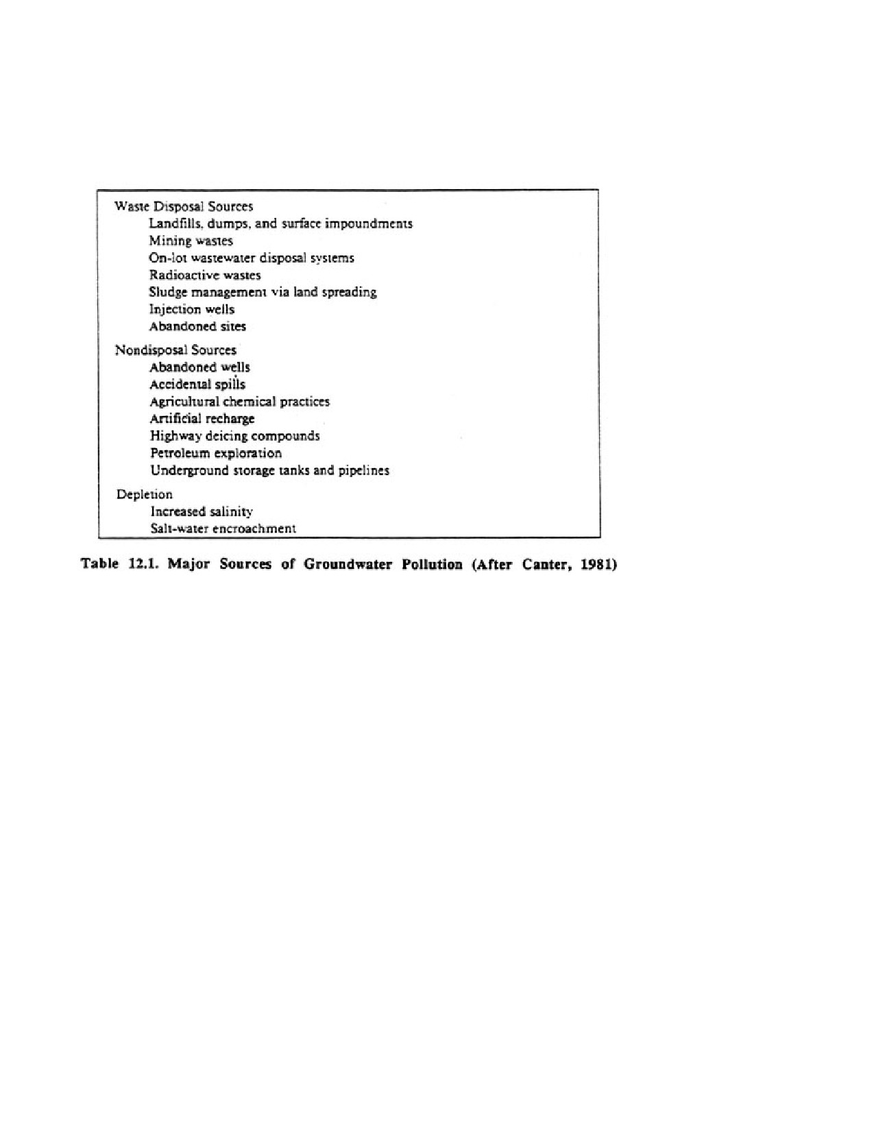
The major threats to groundwater quality Mom all contaminant sources are (1) septic tank
systems, (2) sanitary landfills, (3) chemical landfills, and (4) wastewater disposal ponds. The
presence of any of these sources can have a pronounced impact on groundwater quality
(Table 12.1). The total number of active hazardous and nonhazardous industrial and
municipal waste sites is estimated at 141,000 (U.S. Environmental Protection Agency,
1980b). Furthermore, there may be more than 150,000 inactive sites that may be potential
threats to groundwater quality. The U.S. Environmental Protection Agency (EPA, 1980b) has
indicated that, of the 32,000 to 50,000 disposal sites that may contain hazardous waste, 1,200
Page 163 of 360
to 2,000 could pose serious health or environmental problems. Until recently, about 80
percent of hazardous wastes were being disposed of improperly in landfills or lagoons and
they will present a long-term threat to groundwater quality.
Another U.S. EPA report, The Surface Impoundment Assessment, suggests that 181,000
impoundments exist at 25,800 industrial sites. A study of 8,200 of the industrial sites shows
that (IJ.S. EPA, 1980b):
1. 70 percent of the impoundments are unlined and possibly allow contaminants to enter the
ground.
2. 10 percent of the sites that are unlined overlie usable aquifers and are on permeable soils.
One-third are within 1 mi of a water supply well.
3. About 35 percent hold liquid wastes that may contain hazardous constituents.
4. As of 1980, only 5 percent of the sites were known to be monitored.
The degree of the contamination threat to groundwater supplies from landfills and
wastewater ponds depends on several factors: toxicity and volume of the contaminant
generated at each site, the nature of the geologic medium underlying the site, and the
hydrologic conditions dominant in the area.
The recent discovery that many volatile organic chemicals are emanating from landfills and
industrial disposal ponds is disturbing because they are known or suspected carcinogens and
are not removed easily by natural geochemical processes in the ground. Many of These
organic chemicals were found in a high percentage of wells recently tested by the U.S.
Page 164 of 360
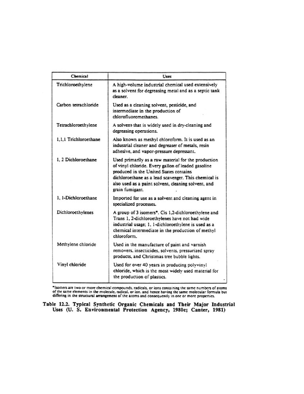
Environmental Protection Agency. The chemicals listed in Table 12.2 occur in groundwater
in many industrial areas and in groundwater adjacent to municipal landfills.
Other less obvious threats to groundwater quality come from a variety of sources. For
example, abandoned wells can be a severe problem if poor-quality water enters aquifers
having good-quality water via uncemented well bores. This problem is especially serious in
agricultural areas, where animal wastes, pesticides, and herbicides can easily enter the
groundwater system through open well bores. In many coastal communizes in Florida and
California, salt-water encroachment caused by overpumping of fresh-water supplies is a
major problem. In the North, heavy and often indiscriminate applications of road deicing
Page 165 of 360
salts, and poorly constructed (uncovered) storage areas, can lead lo high chloride
concentrations in underlying aquifers.
Leaking gasoline storage tanks at automotive service centers, most of which have been
installed in the last 35 years, are a serious local problem in an increasing number of
communities. This type of pollution is especially detrimental because drinking water
becomes unpalatable when it contains extremely low concentrations of petroleum products
(Clean Environment Commission, 1976).
Another example is the broad range of pesticides being applied to farmland. This nonpoint
source of potential contamination is extremely difficult to control. Any type of injection well
can also create a water-quality problem if some of the wastes reach an aquifer containing
good-quality water. Especially serious are radioactive wastes. These substances are
extremely dangerous to humans for anywhere from 30 to 500,000 years. Yet, while the
volume of these wastes has risen dramatically, no safe disposal sites have been identified or
built. Early attempts to bury radioactive wastes have been largely unsuccessful because the
wastes could not be prevented from contaminating groundwater supplies. Most
nuclear-power generators are now storing their wastes aboveground at plant sites until safe
sites can be identified.
Efforts to control contamination problems by regulation have been initiated by federal, state,
and local governments. Common methods of control include:
1. Reducing the volume of material to be discarded by compaction, incineration, or other
pretreatment schemes.
Page 166 of 360
2. Selection of disposal sites that utilize the natural ability of the underground environment to
remove contaminants, thereby preserving groundwater quality.
3. Improving engineering aspects of disposal sites, such as the addition of leachate collection
systems, installation of double clay liners, or the use of synthetic liners.
12.3. EFFECT OF AQUIFER CHARACTERISTICS ON THE SPREAD OF
GROUNDWATER CONTAMINATION
In the past, the least expensive and most widely used waste management option for both
municipal and industrial wastes has been the sanitary landfill, where wastes are compacted
and covered with earth. In any geographic area other than arid zones, the fill is subjected to
percolating rainwater or snowmelt which eventually flows out the bottom of the landfill site
and moves into the local groundwater system. These percolated waters, known as leachates,
can contain large amounts of inorganic and organic contaminants. At some sites, the leachate
is collected and treated. But even in the best engineered sites, some leachate escapes into the
groundwater system because no permanent engineering solution has been found to isolate the
leachate completely from the groundwater.
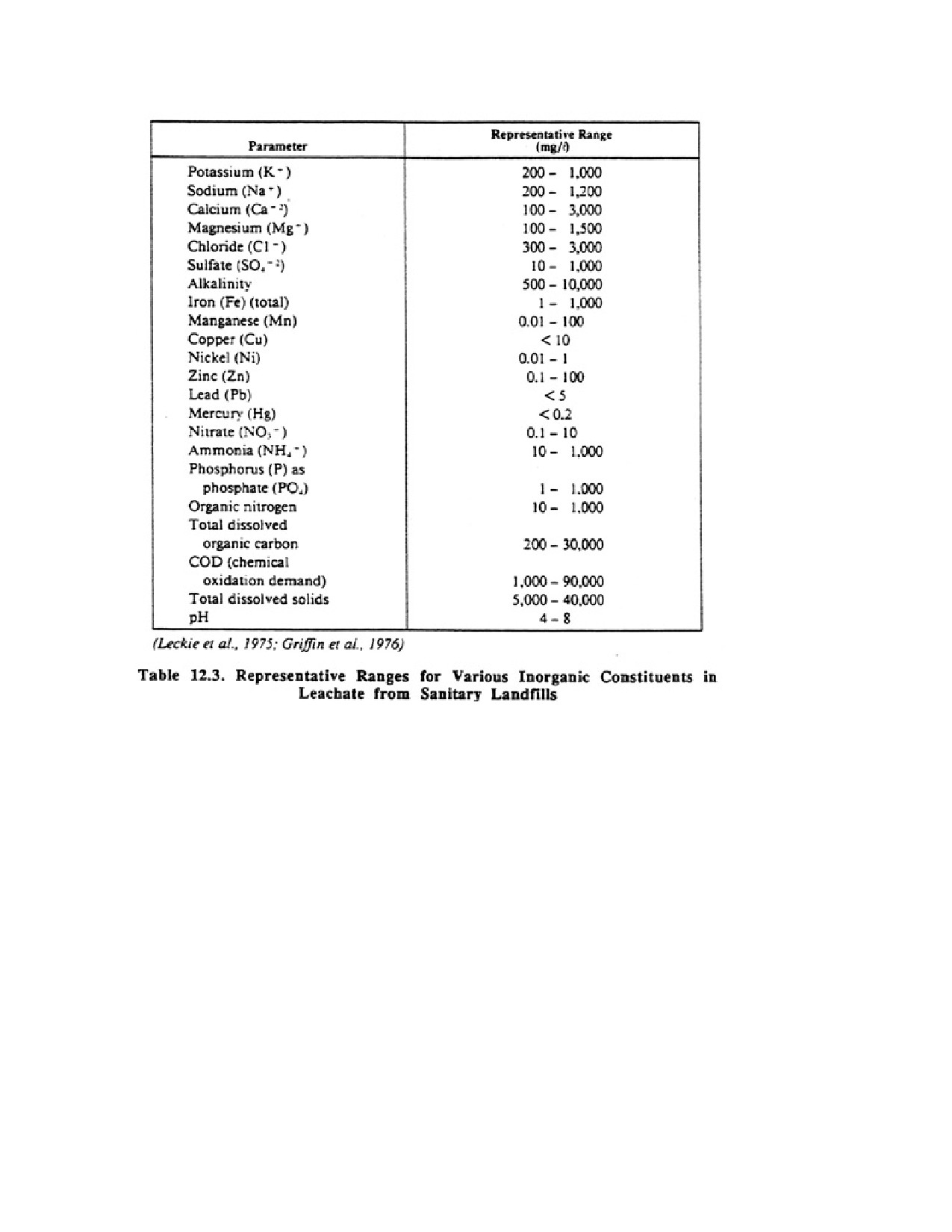
Common inorganic constituents found in leachates from sanitary landfills are listed in Table
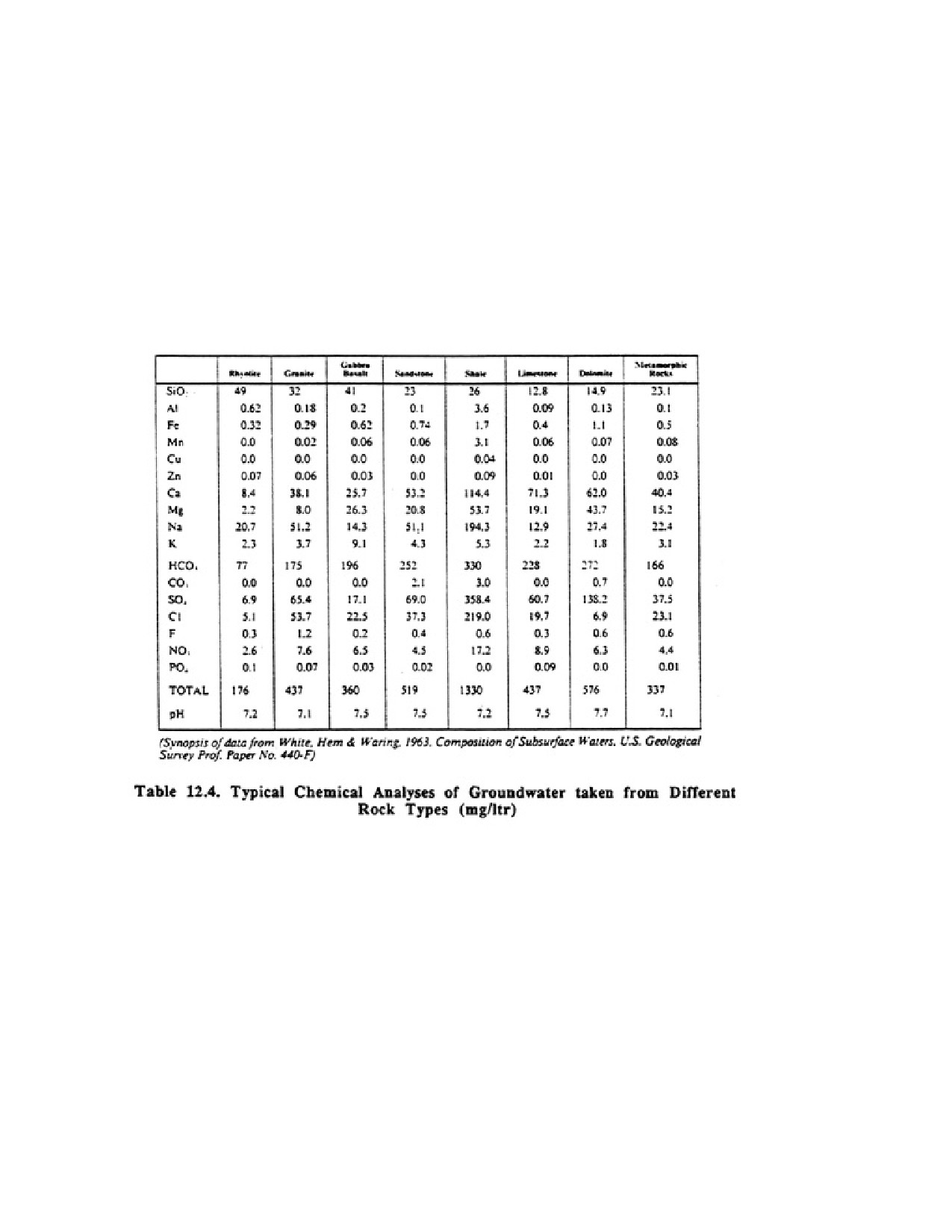
12.3. The concentration of inorganic materials in leachates can be compared with the typical
Page 167 of 360
inorganic levels found in groundwater existing in various rock media to determine the
leaching effect of water percolating through a waste site (Table 12.4). It is not known how
long leachates continue to contaminate aquifers underlying landfills, but some landfills from
the Roman Empire are still producing leachate (Freeze and Cherry, 1979). Contamination
plumes can spread thousands of feet down gradient from a source, and once in the ground,
they may remain there for many years even if the contaminant source is removed.
The hydrogeologic setting plays a role in determining the degree to which a landfill can alter
water quality in local aquifer systems. The type of soils and their ability to adsorb
contaminants, how far the landfill is situated above the water table or confined aquifer,
Page 168 of 360
and the hydraulic properties of the aquifer contribute to or reduce contaminant
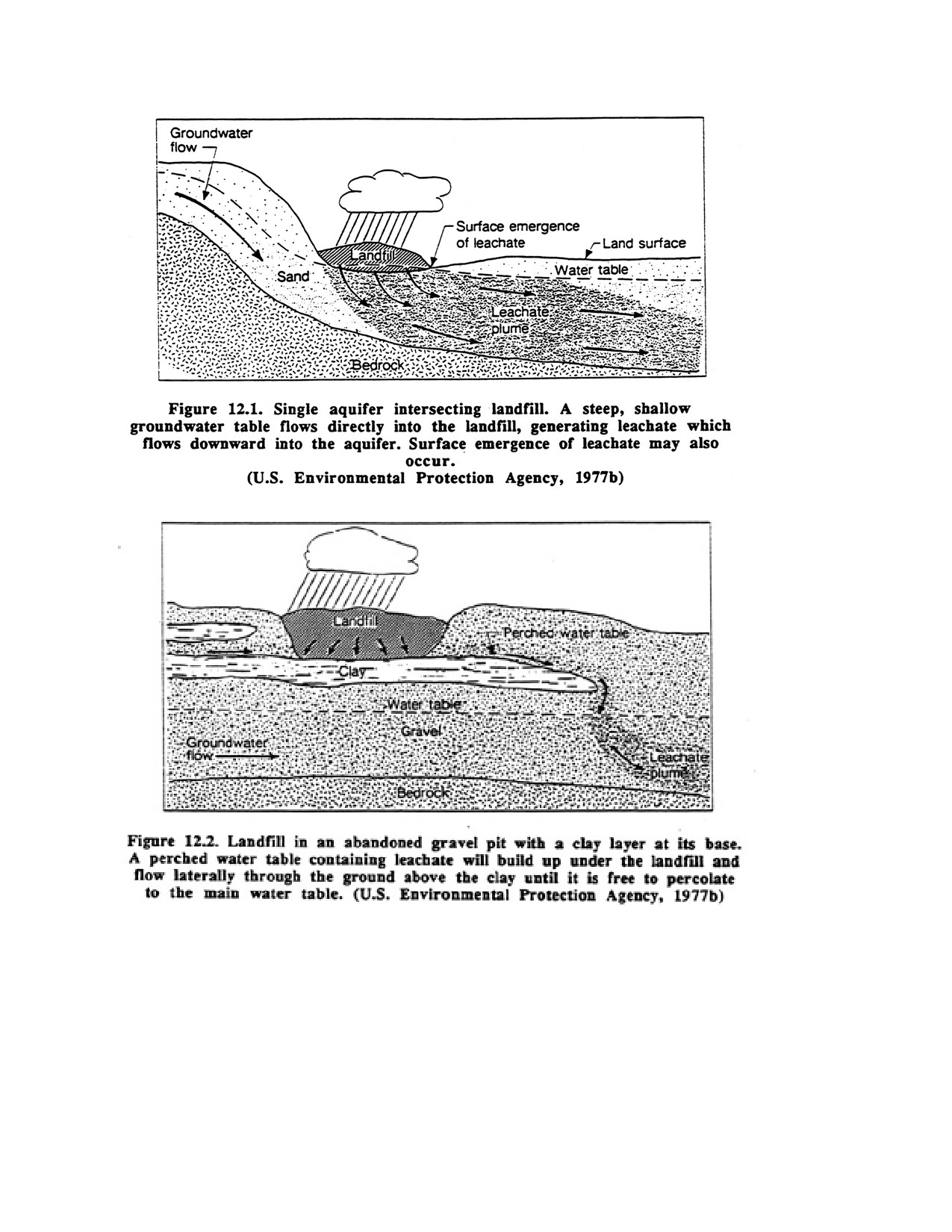
concentrations. Two typical geologic settings are presented in Figures 12.1 and 12.2 that
demonstrate the interaction between the landfill leachates and the local hydrogeology. These
illustrations are instructive in showing the potential flow paths taken by contaminants.
Drilling contractors and engineers should become familiar with potential contaminant flow
paws in any waste project area' because regulations require that most monitoring wells be
placed downgradient Cam the contaminant source. Initially, an estimate of the dimensions of
the plume must be made on the basis of assumed hydraulic conductivity, porosity, and
dispersion values for the aquifer. Any boundary conditions such as faults or changes in rock
type must also be considered. It is important to recognize that some contaminants will
Page 169 of 360
become soluble in water, whereas others such as hydrocarbons will float on the surface of the
groundwater. The density of a soluble contaminant relative to that of water will affect its
penetration into the aquifer.
In the discussion below, flow of the contaminant through the vadose wne will not be
considered, but the reader should be aware that many forms of instrumentation, mainly
lysimeters and various types of electrical and nuclear sensors, can be used to monitor this
zone.
Once in the aquifer, the primary driving force for contaminant movement is created by the
hydraulic gradient that produces groundwater flow. Contaminants entering the groundwater
system are thus carried downgradient, forming a contaminant plume. This type of
contaminant movement is termed "advection." Other factors also influence the shape of the
plume, including two types of hydrodynamic dispersion—mechanical mixing and molecular
diffusion. These two processes cause a spreading (dispersion) of the contaminant over a much
larger area than advection alone would produce, and, consequently, a dilution of the
contaminant away from the source area Mechanical raining processes include velocity
differences within the pore openings, velocity differences caused by differences in pore sizes
through which the water molecules move, and the degree of tortuosity (length) of the pore
channels.
Molecular diffusion (chemical dispersion) can also occur. In the absence of any groundwater
movement, a slug of highly concentrated chemical will move outward from its origin toward
points of lower concentration. This type of dispersion occurs because of the kinetic activity
of the ionic or molecular constituents. The effect of molecular diffusion on contaminant
dispersion is usually much less than the effect of mechanical mixing processes, and except in
the case of no groundwater movement at all (an improbability), it can probably be ignored in
most instances in estimating the spread of contaminant plumes. An exception occurs with
light organic chemicals which have moved upgradient in some cases.
Page 170 of 360
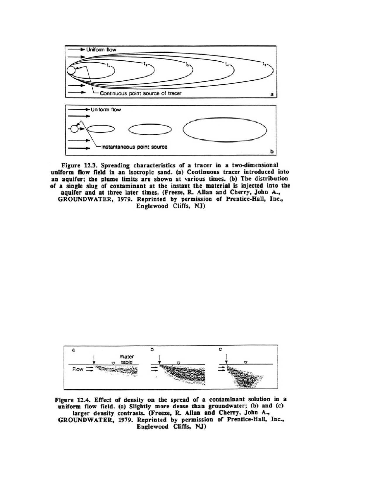
It is possible to project how a contaminant plume actually spreads by advection and
mechanical mixing. Figure 12.3a shows the theoretical downgradient movement of a plume
from a continuous contamination source. Note the marked dispersion of the contaminant as it
moves downgradient. Depending on the exact nature of the aquifer, the dispersion may be of
even greater magnitude than the longitudinal movement (advection) shown in Figure 12.3a.
In Figure 12.3b, a contaminant is injected periodically into the aquifer. Mechanical mixing
coupled with advective flow creates the ellipsoid-shaped plumes. Clearly, the larger the total
area covered by the plume, the more diluted the contaminant becomes.
The density of the contaminant plays a part in determining the vertical dimensions of the
plume. If a material entering an aquifer is heavier than water, it sinks slowly as it disperses
transversely and longitudinally. The density of the material in relation to water, as well as the
hydraulic nature of the aquifer, will govern the vertical penetration of the plume as it moves
downgradient (Figure 12.4).
Many chemical and biochemical reactions can take place in the subsurface environment to
either augment or, more likely, reduce the concentration of a contaminant. The most
Page 171 of 360
important of these are solution-precipitation, oxidation-reduction, adsorption-desorption,
acid-base reactions, and microbial cell synthesis. Some of these reactions may take place in
the unsaturated zone before the contaminant reaches the aquifer. Once in the aquifer,
different contaminants in the same plume may travel at different velocities depending on how
they react with the geologic medium. Any investigation of groundwater contamination
should include an analysis of the chemical or biological reactions taking place and the effect
of these reactions on the strength of the contaminant plume.
In summation, many factors play a part in the spreading and concentration rate of a
contaminant: anisotropic/isotropic properties of the rock medium, advection rate,
hydrodynamic dispersion processes, and reaction potential with the subsurface materials.
Therefore, underground movement of groundwater contaminants is often exceedingly
difficult to analyze in a straightforward manner. Many sophisticated methods are now being
used to determine contaminant movement, including special mathematical modeling
techniques, electrical (surface resistivity) methods, radioactive tracers, various dyes and salts,
water temperature, and baker's yeast. Some of these techniques are discussed later in this
chapter.
12.4. DELINEATING CONTAMINANT PLUMES
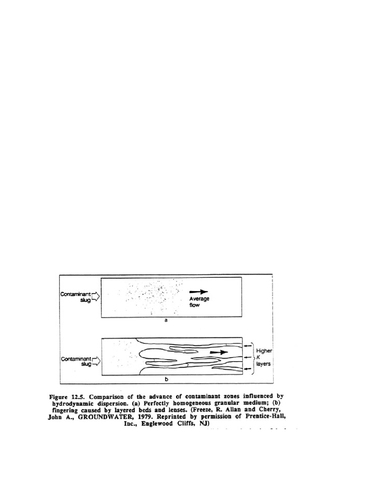
Openings in rocks or unconsolidated materials are not regularly spaced, and the permeability
of the aquifer material varies both vertically and horizontally. Thus, the flow of contaminants
is highly anisotropic (Figure 125). In spite of these difficulties, it is necessary to estimate
flow direction within the aquifer so that the source of contamination and the direction of
plume movement can be determined.
Usually, the general direction of groundwater flow can be established on the basis of the
local topography (use of topographic maps or aerial photos) and the presence of streams or
Page 172 of 360
rivers which act as groundwater discharge boundaries. Recall that near-surface groundwater
flow will generally follow surface drainage patterns. If the flow direction cannot be
established, three small-diameter wells are temporarily installed into the aquifer. An analysis
of the relative water table or potentiometric surfaces in the wells will reveal the direction of
flow. For anisotropic aquifers, however, the direction of flow may not be parallel to the
hydraulic gradient.
To determine the dimensions of a plume, test borings can be made and water samples taken.
Several borehole geophysical methods are used in defining the extent of plumes; the most
important of these are resistivity, conductivity, neutron, hole caliper, and temperature.
Resistivity and conductivity values of the groundwater are affected by the contaminating
substance and thus are an indication of the plume's presence at a site. Gamma ray and other
nuclear methods provide information on subsurface Ethology, particularly zones that have
high permeability. It can be expected that contaminant migration will be greatest in these
zones. Hole calipers indicate the presence of solution channels penetrated by a borehole in
hard terrains. Temperature logs are useful in tracing the movement of injected water in
highly permeable zones and detecting any changes in flow rate over time.
12.5. MONITORING CONTAMINANT MOVEMENT (TRANSPORT)
In many instances of groundwater contamination, the ability to predict how the contaminant
plume will behave in the future can only be done on the basis of expensive drilling and
sampling programs. Many scientists interested in the movement of contaminants in the
subsurface believe, however, that it will soon be possible to use mathematical modeling
techniques to estimate the spread of a contaminant and its strength at any point in the plume.
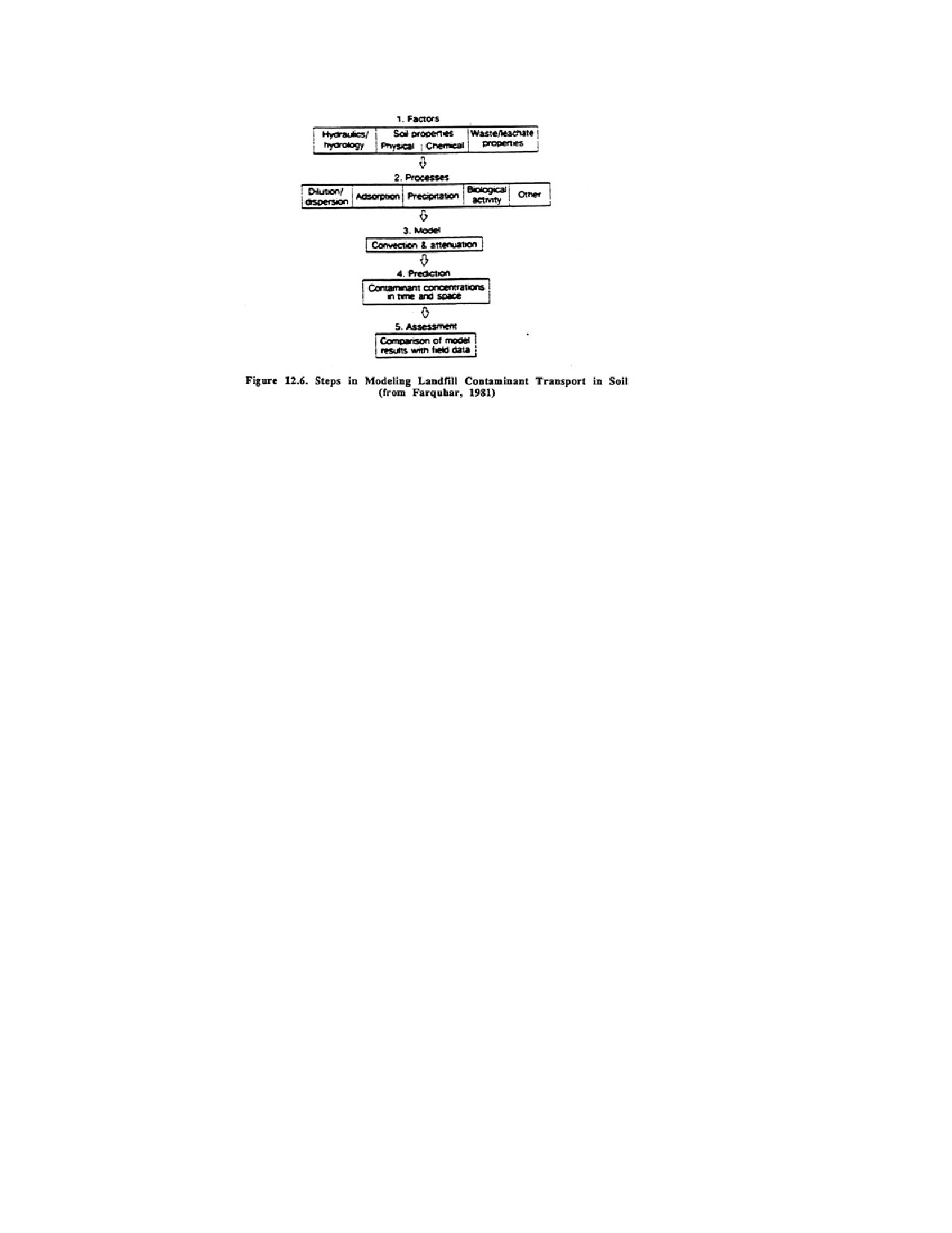
The steps or processes used to build the model are shown in Figure 12.6. Five basic steps are
accomplished in sequence:
1. In the first step, the basic factors affecting contaminant transport are identified—hydraulic
characteristics of the aquifer, the physical and chemical properties of the aquifer materials,
and the chemical and physical properties of the contaminants entering the groundwater
system.
2. The attenuating processes for single chemicals are established. Different chemicals will
move at varying rates and therefore occur at different concentrations in the aquifer.
3. In the third step, a mathematical model is set up to account for the attenuation processes,
and a method of solving the equation is determined.
4. Predictions are made on the basis of the answers obtained in Step 3 for the occurrence of
the various contaminant in the aquifer at a particular time.
5. In the last step, the validity of the model is assessed by comparing the model's results to
any known field data. If the results differ significantly, the various model inputs are adjusted
to produce better carnation with the field data.
Page 173 of 360
In this modeling process, the factors identified in Step 1 are the most difficult to determine.
This is true because the construction of virtually all aquifers is highly complex, with little
uniformity either vertically or horizontally. Thus, it is difficult to predict how fast the
contaminants will move through the aquifer, at what depth, and over what area they will be
dispersed within a certain time. Furthermore, the geochemical attenuation mechanisms for
many chemicals are not thoroughly understood. For these reasons, some transport models
have not yielded good results, and field data are much more reliable. Many groundwater
scientists are working on ways to improve model accuracy, however, and, because the use of
a model can be so much less costly than field work in estimating plume dimensions and
contaminant concentrations, the use of contaminant transport models will probably increase
significantly in the future.
Even though the mathematical analysis and the complex geochemical relationships that are a
fundamental part of any contaminant transport model may be beyond the experience of most
drilling contractors, much of this information will probably be available as "canned" models
adaptable to a wide range of geologic situations. The contractor or consulting hydrogeologist
will then be able to use the models to define a cost-effective field drilling program. Results
from the field data can then be used to calibrate the model for the specific site.
12.6. LOCATING MONITORING WELLS
Once the areal extent of the plume has been defined, several monitoring wells are installed in
or adjacent to the plume. The purpose of a monitoring well is to (Lewis, 1982):
1. Determine the hydrogeologic properties of the formation in which the contaminant exists.
2. Determine the water table or potentiometric surfaces of all aquifers in the system.
3. Permit access for the collection of water-quality samples for detection of contaminants
4. Monitor the movement of the contaminant plume.
Usually one well is sited near the center of the plume just downgradient from the
contaminant source. Another well is installed downgradient of the contaminant source,
outside the limits of the plume. For ambient environmental data, one well is placed
Page 174 of 360
upgradient of the contaminant source. Other wells may be installed to verify the amount of
dispersion taking place. The most difficult decision is rarely where to place the monitoring
wells, but at what depths should the samples be taken. Selection of the most appropriate
depths will depend on the density of the contaminant, the anisotropic characteristics of the
aquifer, and the slope of the water table or potentiometric surface. The design of the
monitoring network is extremely important if maximum information concerning the extent of
the contamination is to be obtained.
In the past, too few monitoring wells were required for each disposal site. Thus it was not
possible to adequately monitor contaminant movement. In practice, the number of wells
required to adequately monitor a specific disposal site will vary greatly, depending on the
local hydrogeology. If the disposal site is higher than the surrounding landscape, for
example, leachates may flow some distance in all four directions. In this instance, at least
four wells would be needed, plus one other to monitor the upgradient chemistry. Ideally,
some wells would be installed at more than one depth in the aquifer to verify if vertical flow
is occurring or if the spread of the contaminant varies at different depths. Proper placement
of monitoring wells must be based on accurate information concerning the groundwater flow
direction at the waste disposal site and the type of contaminant.
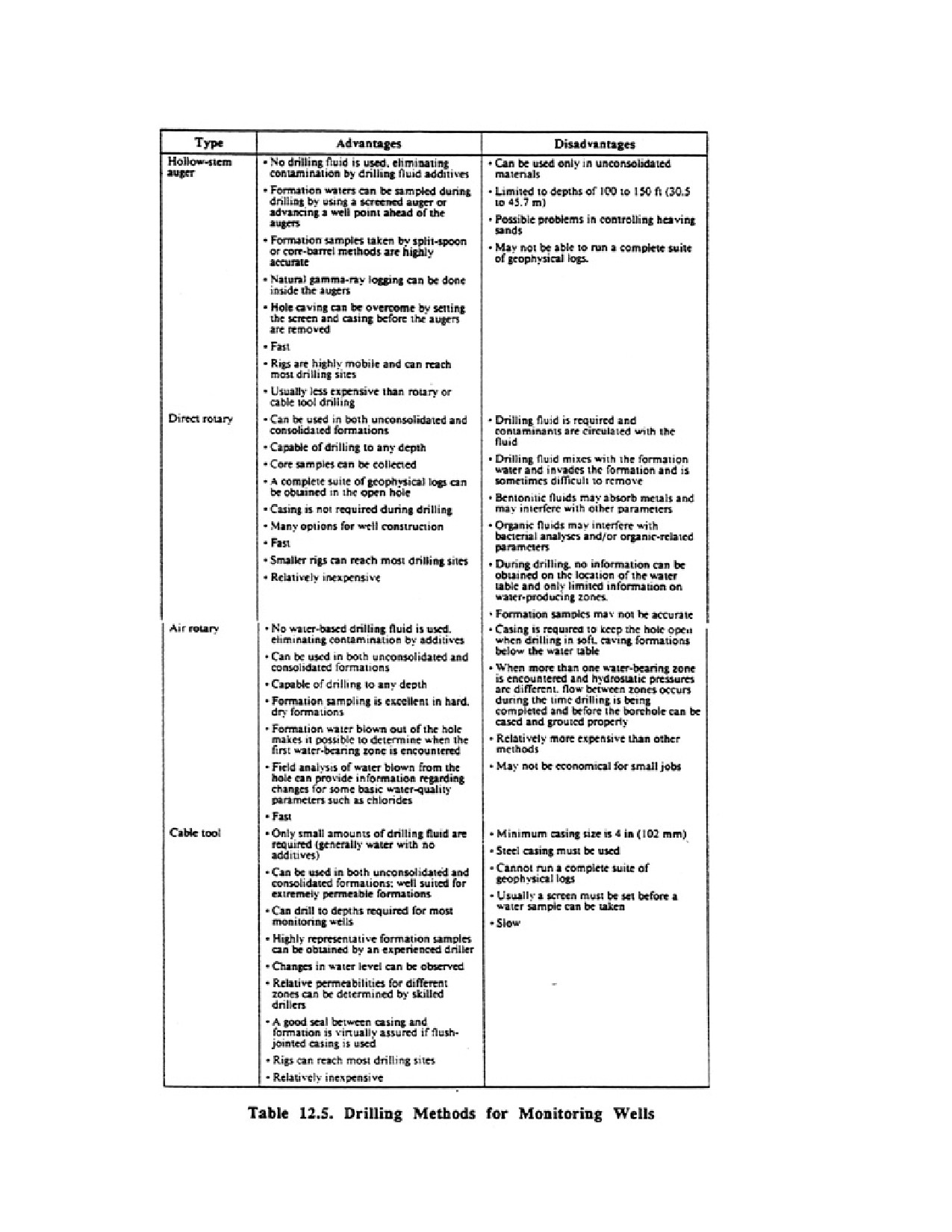
Although monitoring wells can be drilled by virtually any drilling method, some methods
may be more suitable in certain situations. Table 12.5 lists the major methods used to install
monitoring wells, and their advantages and disadvantages.
For monitoring work, many of the objectives of a drilling program are similar to those for a
water well, but some of the steps must be done with greater care to insure that the water
quality is protected and reliable water samples can be obtained. Specific steps in monitoring
well construction include:
1. Ability to penetrate all formation materials at a reasonable rate and to construct a borehole
diameter of the proper size, assuring that cross-contamination will not occur.
2. Ability to provide accurate information on all the formations being drilled.
3. Containment of cuttings and drilling fluids so they do not contaminate the formation.
4. Collection of water samples at various depths during drilling.
5. Ability to accommodate for lost-circulation problems, confining pressures, and flammable
and toxic substances.
6. Construction of the monitoring well either during the drilling process or immediately
thereafter.
7. Ability to maintain an open borehole long enough for geophysical exploration (if required)
and data analysis.
Page 175 of 360
Page 176 of 360
12.7. PERSONNEL SAFETY AT MONITORING SITES
Safety should be a primary concern of water well contractors engaged in drilling and
constructing monitoring wells. Besides the usual physical herds of normal drilling activities,
chemical, biological, radiological, and explosive hazards are added when drilling monitoring
wells. So many toxic chemicals have been placed in the ground, either accidentally or
intentionally, that drillers must use extreme caution when drilling in areas of known or
suspected waste sites. In the past, many extremely toxic chemicals were mixed
indiscriminately into ordinary municipal waste streams. Even the innocent disposal by
homeowners of many dangerous organic chemicals has led to their introduction into the
groundwater system beneath sanitary landfills. Unfortunately, the exact location or the extent
of many former waste disposal sites are not known with precision. Furthermore, many
chemicals may appear to be harmless and any injury may be rather insignificant on a
short-term basis. Yet long-term effects may be acute, causing premature death, unusual forms
of cancer, or generally poor health.
Some of the most significant dangers are:
1. Explosions from methane gas produced by the decay of organic materials in sanitary
landfills. An explosion potential also exists in monitoring work involving hydrocarbon
recovery.
2. Toxic substances used in manufacturing pesticides, herbicides, solvents, paints, and other
common products. Sometimes certain nontoxic chemicals placed in a disposal site will react
with other chemicals to produce highly toxic chemicals.
3. Biologic wastes from hospitals or medical laboratories at universities that contain bacteria
and viruses.
4. Chemical wastes that are corrosive, highly reactive, flammable, or explosive.
5. Vapors from any type of waste.
6. Radioactive wastes from hospitals and industrial and university laboratories.
One vital fact must always be kept in mind—the combination of substances at a waste site
may have a more powerfully adverse effect on human health than they would individually.
Before attempting to conduct monitoring work at a waste site, the drilling contractor should
learn exactly what types of wastes were buried there, provide the necessary protective
clothing and training for personnel, and stress that any physical changes in a worker's health
may be caused by contact with the waste. Always be prepared for "worst case" conditions.
Any form of drilling is relatively dirty in the sense that it is difficult to avoid contact with
cuttings, water encountered in the borehole, and surficial residues at the site. The following
practices must be followed at any known or suspected hazardous waste site. (Maslansky,
1983)
Page 177 of 360
1. "Personnel should wear properly selected and fitted protective clothing and respirators at
all times. Personnel must be given suitable training in the use, limitations, maintenance,
cleaning, and storage of protective clothing and equipment."
2. "Personnel should not eat, drink, chew gum or tobacco, smoke, take medicines, or perform
any other practice that might increase hand-to-mouth transfer of toxic materials from gloves,
unwashed hands, or equipment."
3. "Personnel should not have excessive facial hair (heavy mustaches, beards) which can
prevent the proper fit of respirators."
4. "Personnel should avoid unnecessary contact with hazardous materials by staying clear of
puddles, vapors, mud, discolored surfaces, and containers or site debris."
Carelessness during routine daily activities at the site can lead to serious personal
contamination or to contamination of others. Several important habits should be practiced:
1. Always wash hands before using rest room.
2. Leave the site for lunch, removing all protective (contaminated) clothing, and wash
thoroughly.
3. Wash hands after handling contaminated equipment.
4. Do not take contaminated clothing home to launder.
5. Wear the required protective clothing at all times, even if the need is not apparent.
Demand that it be fitted properly. Even a short exposure to a toxic substance can be deadly.
6. Because protective clothing is cumbersome to wear and is often uncomfortable in hot
weather, take appropriate rest periods to avoid accidents caused by fatigue or physical
irritation.
Even if every safety precaution is taken, an emergency may develop at any time when doing
monitoring work. Emergency plans should be well established and understood by everyone
involved in the project. First aid equipment should be available, the routes to emergency
care centers known, and the necessary personal contacts established at the care centers. All
steps of the standard emergency procedures should be practiced so that any team member can
take charge.
Page 178 of 360
12 8 DESIGN OF MONITORING WELLS
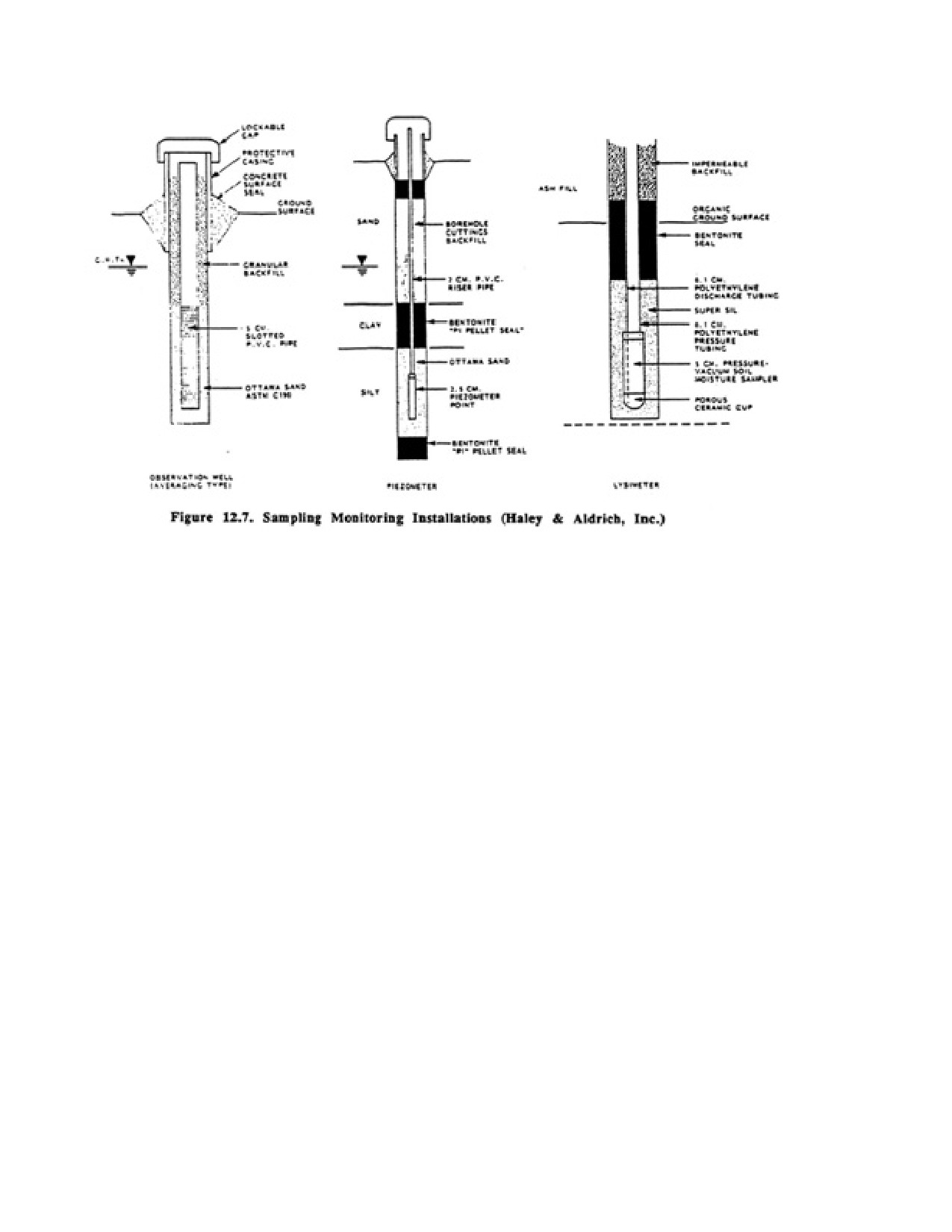
Figure 12.7 shows typical observation well, piezometer, and lysimeter construction schemes.
The particular design of a monitoring well will depend on (l) how the well is to be used—
whether for taking water samples for measuring the elevation of the water table or
potentiometric surface, or for recovering contaminants, (2) the hydrogeologic environment,
(3) the chemical nature of the contaminants, and (4) whether the well bore will be used to
conduct geophysical investigations. The design consultant should keep in mind that the cost
of the best engineered monitoring well constructed of the most suitable materials will be only
a fraction of the long-term costs for water quality analysis. Therefore, the most suitable well
materials and construction practices should be selected for monitoring wells.
Many monitoring wells are constructed of 2-in casing and screen, although a large number
are 4, 6, or 8 inches in diameter. The most appropriate diameter will depend on numerous
site-specific factors. For shallow monitoring wells or those used for measuring water level
and routine sampling 2-in well screens and casing may be suitable. For better development,
deeper wells, or where some form of pumping test or borehole geophysical investigation is
necessary, the screen and casing may need to be 4 inches in diameter. Taking representative
samples from Tin wells is more difficult than for 2-in wells because many pumps
manufactured for sampling 2-in monitoring wells are technically superior to larger pumps in
that they preserve the true chemical character of the sample. They can be pumped at only
extremely low rates, however, making their use impractical in wells 4 inches in diameter or
larger. If 2-in screens are installed in dirty or tight formations, the driller cannot develop the
well properly. Water samples taken from poorly developed wells may not be chemically
representative of the water in the formation because recharge to the well is so slow that the
person who takes the sample cannot spend the time needed to collect a representative sample.
12.8.1. Screen Criteria for Monitoring Wells
Page 179 of 360
Well screens used for monitoring work should have the following characteristics:
1. Screens should be constructed from a material that is inert in the water being tested.
2. Open area should be maximized to facilitate rapid sample recovery.
3. Slot sizes should retain filter pack or natural formation consistent with the capability to
develop the welt
4. Slot openings should be nonplugging in design.
5. Slot openings, slot design, open area, and screen diameter should permit effective
development.
Selection of the screen material must be done with care because many common screen or
casing materials such as PVC, low-carbon steel, and even stainless steel may react with the
groundwater, producing erroneous water quality data In general, the following factors should
be considered when selecting screen and casing materials:
1. Contaminants to be sampled
2. Chemical reactiveness/inertness
3. Strength of material
4. Ease of installation
5. Cost of material
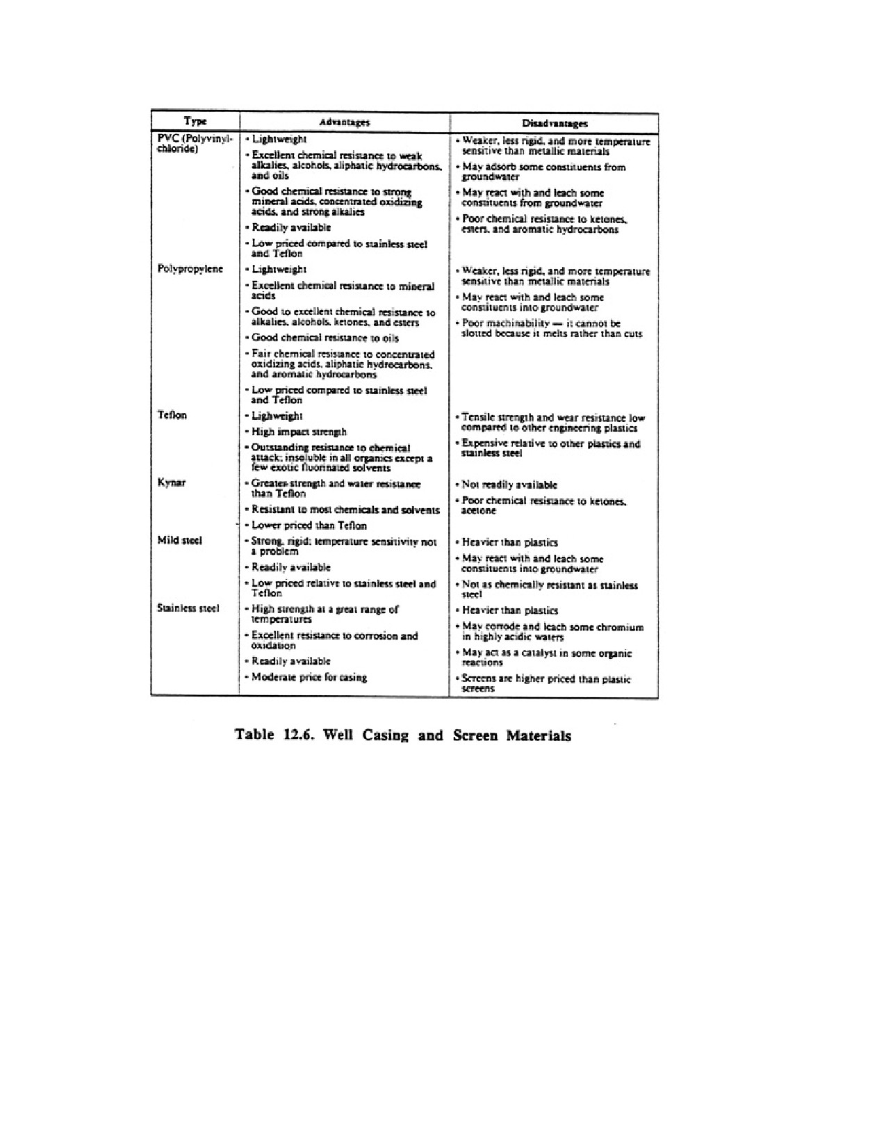
Table 12.6 lists the major types of materials used for monitoring wells, along with
recommendations for their use. Teflon (Teflon is a registered trademark of E.I. DuPont
DeNemours and Co., Inc.) is the most inert material currency being used, but its cost may
make its use inappropriate in groundwater environments where less costly materials are
satisfactory. PVC materials are suitable for monitoring most landfills unless organic
chemicals are present in the groundwater. If they are present, stainless steel or Teflon
materials must be used. Relatively inert metals such as 304 or 316 stainless steel are not
suitable for groundwater in which heavy metals are present, because leaching of chromium or
other metallic components may occur. Selection of the screen and casing material generally
depends upon die chemical manure of the groundwater, not cost of the screen or casing
material the laboratory doing the analytical chemistry of the water samples should be
informed of all materials used in the well.
Page 180 of 360
Screens used for monitoring are almost always placed in materials having extremely low
hydraulic conductivity. If possible, the open area of the screen should approximate the
natural porosity of the formation, that is, 15 to 20 percent, so that the tune required to take a
representative sample is minimized. Because most sampling methods require that a water
sample be taken only after 3 to 10 well-bore volumes have been removed, the amount of time
dedicated to taking a single sample can be excessive if low-open area screens are installed.
Screen slot sizes must retain a high percentage of the filter pack or natural formation for all
2-in wells because effective development of these wells is particularly difficult. For larger
diameter monitoring wells, the slot sizes can more nearly follow the recommendations for
water wells. Development is most effective when the slot openings are distributed uniformly
around the circumference of the screen so that as much of the formation and filter pack as
possible can be reached by the development action. The configuration of the slot should
permit all the development energy to reach the formation.
Page 181 of 360
Slot openings should widen inward so that finer formation materials are pulled through the
screen during development. Slots that are cut straight through the casing or those of the gauze
type will tend to plug with fine material during development, thereby reducing significantly
the open area of the screen. This is especially true for 2-in screens where any development
that is done is relatively inefficient. Plugging of the slots increases the time needed to obtain
a representative sample from the formation. For scientific purposes, water samples from
monitoring wells are usually obtained from relatively thin zones in the aquifer. This can be
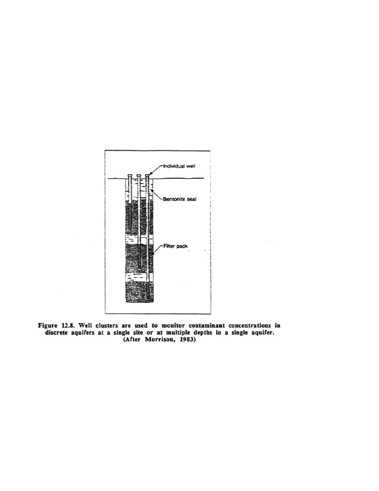
accomplished by using multiple wells with short screen segments. Commonly, a nest of weds
win be installed in single or multiple boreholes to gather water samples from several depths
in the aquifer (Figure 12.8). Using this method, the vertical dimensions and contaminant
strength of the plume can be determined.
Screens used for collecting water samples are typically 5 to 10 ft in length, because samples
should come from specific depths and high yields are relatively unimportant. The well yield
should be high enough, however, so that a reliable water sample can be collected quickly.
Screens that monitor groundwater quality at the top of the water table are usually 10 to 20 ft
in length, depending on the anticipated long-term changes in groundwater elevation. Some of
the screen is always above the water table in the vadose zone. These screens are then used to
monitor for the presence of hydrocarbons or other volatile substances that have reached the
groundwater table.
12.8.2. Filter Pack Design
Page 182 of 360
Monitoring wells are generally installed in formations having a wide range of particle sizes,
which makes it difficult to filter pack effectively. Filter packing procedures recommended for
water wells are not suitable for monitoring wells unless the hydraulic characteristics of the
formation materials are similar to those of an aquifer. To exclude the entrance of fine silts,
sands, and clays into a monitoring well, the grainsize distribution curve for the filter pack is
selected by multiplying the Percent retained size of the finest formation sample by 2. This
leads to a more conservatively sized filter pack than would be selected for a water well.
Selection of too fine a pack will reduce the yield of the well, causing longer sampling times.
Uniformity coefficients for filter pack material should range from 2 to 3. All pack material
should be purchased from reputable suppliers who have properly cleaned and bagged the
material A sample of the cleaned filter pack should be collected and chemically analyzed in
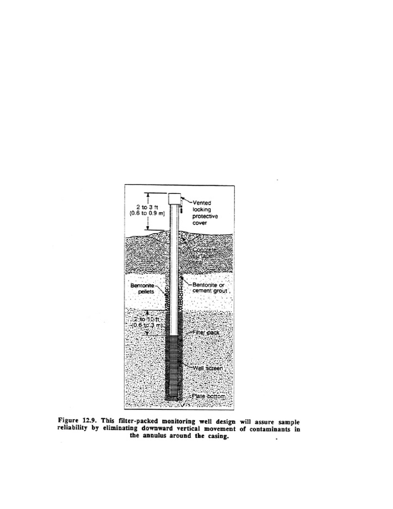
the event questions are raised regarding possible contamination from the pack The design of
a typical filter-packed monitoring well is shown in Figure 12.9.
12.8.3. Installation Procedures
Page 183 of 360
All screens and casings used for monitoring wells should be in a sterile and contaminant-free
condition when placed in the ground. Some manufacturers ship their products in this
condition, but handling in the field requires a final wash with detergent or other solution.
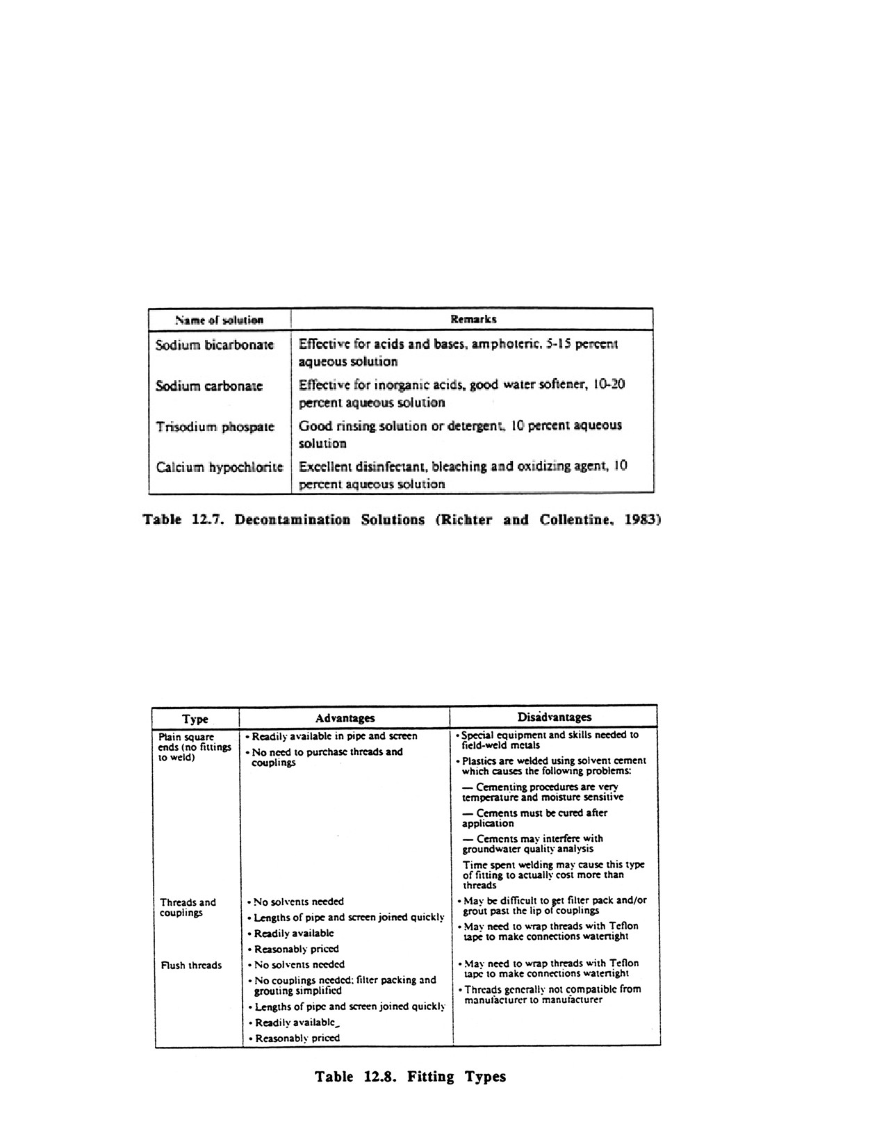
Table 12.7 lists typical decontamination solutions. Some form of steam cleaning, or
high-pressure water-spraying technique combined with a low-sudsing soap or detergent, is
recommended. In addition, acetone and hexane are used to clean drilling tools and sampling
equipment at hazardous waste sites. Working components of the drilling rig (drill pipe, subs,
collars, kelly. and all parts of the rig chassis near the borehole) should also be cleaned
The method of joining screens to casing and of assembling the casing string must also be
done so as to prevent contamination of the samples. In general, no solvent welds are
recommended; all plastic screens and casing should be joined by threads and couplings or
flush threads. The joints are made watertight by wrapping with Teflon tape or by placing a
Teflon or Viton (Viton is a registered trademark of E.1. DuPont DeNemours and Co., Inc.)
O-ring in the joint (Table 12.8).
Page 184 of 360
A ply objective of monitoring well construction is to make sure that contaminated
groundwater does not enter contaminant-free geologic formations. Although some minor
amount of cross-contamination may occur during drilling and well installation, the integrity
of individual formations must be protected thereafter. This is usually accomplished by
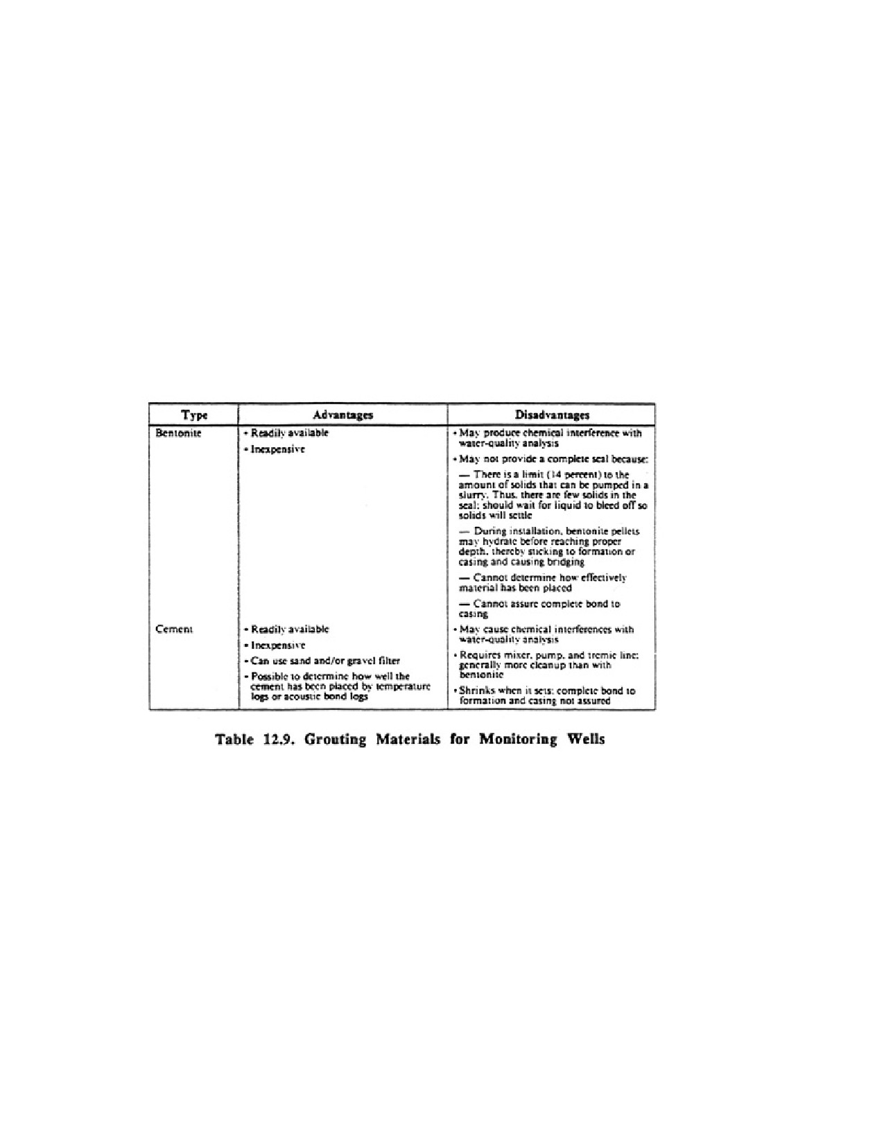
placing either bentonite or cement grout in the borehole above the filter pack in both single-
and multiple-screen wells. Drill cuttings should not be placed in any open borehole annulus.
To prevent downward migration of the bentonite or cement into the screen, the filter pack is
extended at least 2 to 10 ft above the fop of the screen. The filter pack should not extend into
an overlying formation, because this would permit downward vertical seepage in the pack
and either dilute or add to the contamination of the water being monitored See Table 12.9 for
a comparison of bentonite and cement grouts. Polymeric fluids are not recommended as an
alternative to bentonite or cement because they contain so few solids. See Chapter 10 for
grout placement procedures.
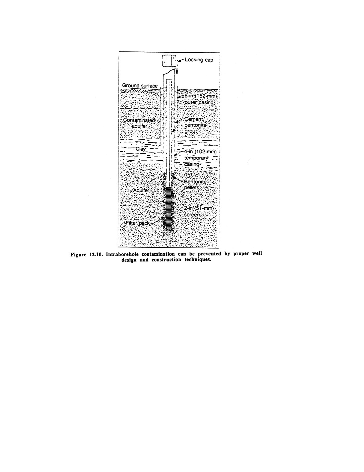
For monitoring wells drilled by cable tool rigs, contaminant migration in the borehole can
generally be eliminated by the well design shown in Figure 12.10. The 6-in casing is first
installed into the clay layer. After flushing the casing and changing the drilling fluid, the
borehole is extended using 4-in casing. A 2-in monitoring well is then installed and filter
packed. Before installing the pack the well bore should be thoroughly flushed. As the Win
temporary casing is extracted, cement or bentonite grout is placed as shown in Figure 12.10.
A protective surface casing with a locking cap is installed before the cement has hardened.
Normally the locking cap will be vented. The well should then be developed as thoroughly as
possible.
If the well is drilled by rotary methods, a 4-in casing can be grouted in an 8-in borehole that
is drilled through the contaminated aquifer into an underlying impermeable layer. After the
grout has hardened, the borehole is continued inside the 4-in casing to the desired depth. A
2-in casing and screen is filter packed and then grouted in the 4-in casing.
Page 185 of 360
In saline environments, a Dowell seal ring gasket (manufactured by Dow Chemical) may be
used in place of bentonite, because bentonite will not hydrate in a highly saline environment.
These gaskets can be made in variable lengths and mounted on the casing just prior to the
installation of the screen. They are suitable for use in regularly shaped boreholes and where
the organic and inorganic compounds in the gasket do not interfere with the chemical
analysis of the water in the welt Cement can be placed above the gaskets to complete the seat
A cement seal around the top of the well bore is recommended even if the annular seal is
carried to the surface. The cement seal is shaped so that surface water flows away from the
casing. If plastic casing is used, a short section of metal surface casing should be installed
around the top section of the plastic pipe and extended 3 to 5 ft into the ground. The metal
casing prevents accidents damage to the plastic pipe. The top of the casing should be fitted
with a locking cap.
Page 186 of 360
Frost heaving can be a major problem for small diameter PVC monitoring wells installed in
cold climates. As the soil freezes during the winter, it expands upward, occasionally pulling
the casing apart. Damage caused by fast heaving can be minimized by placing a metal
surface casing to a depth of 5 to 10 ft. A steeply inclined cement cap should be placed around
the surface casing. If frost action exerts pressure on the cement, the surface casing can rise
without disturbing the monitoring well casing.
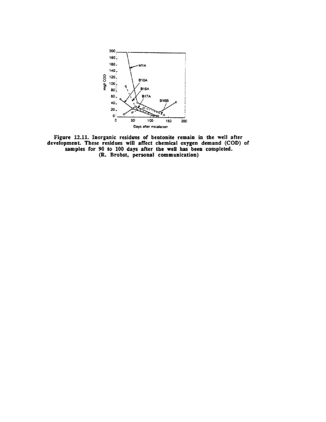
Development is especially important for monitoring wells, because drilling fluid residues
remaining in the borehole will affect the chemistry of the water samples. Figure 12.11 shows
that the presence of bentonite affects the chemical analyses of samples for at least 90 days
after completion of the well. More thorough development shortens the time the bentonite will
affect water quality. In some cases, the impact of drilling fluid additives on sampling
chemistry can last for 1 to 2 years.
It should be stressed that all monitoring wells must be developed as thoroughly as possible,
not only to remove all traces of the drilling fluid from the formation, but also to increase the
yield so at reliable samples can be collected in die shortest time. Development is also
important to assure that the ambient water quality is maintained in the sample container until
the water can be analyzed. Any sediment in the sample container, for example, can react with
the water, thereby altering the actual chemical quality.
Page 187 of 360
12.9. SAMPLING MONITORING WELLS
Sampling of monitoring wells will usually be done by field personnel from the testing
laboratory or by groundwater consultants. Nevertheless, drilling contractors should have an
appreciation of the difficulties in sampling protocol. In general, a sample is taken only after
the pH, electrical conductivity, and temperature of the water being pumped from the well
have stabilized. The methodology used in the sampling procedure is critically important if the
true chemical nature of the groundwater contamination at that site is to be determined.
Samples may not be representative of groundwater conditions for the following reasons:
1 . The sample was taken from stagnant water in the well, which is usually different
chemically from water in the ground near the wed bore. The transmissivity of the aquifer
should be determined so that the consultant can estimate the time required to remove enough
water to obtain a reliable sample. In most wells, a sample is taken after 3 to 10 well-bore
volumes have been removed.
2. Samples were not taken at appropriate intervals. Sampling intervals are usually established
based on the hydraulic conductivity of the formation—the faster the rate of contaminant
movement, the more often samples are taken.
3. The water sample was contaminated by entrained sediment because the wed was not
developed properly. When the sample is acidified for preservation, contaminants adhering to
the sediment, especially metallic ions, are released into the sample.
4. Sample accuracy was adversely affected by the hydraulic character of the formation. A
representative sample may not be obtained when the formation has a high hydraulic
conductivity near the screen and the contaminant is concentrated near the static water level in
less permeable material. In this case, the proportion of uncontaminated water is so high that
the dilution is sufficient to mask the presence of the contaminant.
Page 188 of 360
5. The sample was taken so long after pumping began that it represents water so far from the
well site that the groundwater chemistry is not representative.
6. Release of carbon dioxide during pumping caused an increase in pH which in turn caused
many metallic ions to come out of solution (iron, manganese, magnesium, cadmium, arsenic,
selenium, and boron).
7. Numerous chemical changes took place because the sample was oxidized during recovery.
Oxidation can occur in the pomp or can be caused by water cascading into a well installed in
tight formations. Because many groundwaters are in a reduced state, some of the changes that
can be expected include:
a. Oxidation of organics
b. Oxidation of sulfide to sulfate
c. Oxidation of ferrous iron and precipitation of ferric hydroxide [Fe(OH)3]
d. Oxidation of ammonium ion to nitrate
e. Oxidation of manganese and precipitation of manganese dioxide or similar hydrous
oxides. The water sample became contaminated by chemical residues in the pump or
sampling equipment. If sample recovery equipment is not dedicated to a single well, it
must be thoroughly cleaned each time it is used.
8. The sample was not preserved correctly, so chemical changes occurred in the sample
container during storage. Most samples requiring laboratory analysis are preserved by
immediately wrapping with foil to prevent light from reaching them and then storing
temporarily in a cold environment.
9. The sample was not analyzed quickly enough because either it did not reach the laboratory
within a reasonable time or the lab could not perform the analytical tests soon enough
because of poor scheduling.
10. The testing procedures at the laboratory were not set up properly and therefore did not
yield accurate results. The concentration of a particular contaminant may be in the parts per
billion or even parts per trillion range and the least malfunction in the analytical work can
produce erroneous results. Good testing procedures include sending split samples to different
labs to compare results and submitting spiked samples periodically to check the reliability of
a particular lab's testing procedures. A spiked sample usually contains one or more chemicals
that have been purposely added at specific concentrations.
The single most important parameter affecting the chemical quality of groundwater is pH and
any disturbance in pH during sampling can cause a distinct change in chemistry. In general,
air-lift or nitrogen-lift pumps produce the largest increases in pH during sampling by
stripping excess dissolved carbon dioxide from the-water. Peristaltic and diaphragm pumps
and bailers had less effect on pH. Air-lift pumps also reduce the concentration of volatile
organic compounds. It is a good idea to measure oxidation-reduction potential (Eh), pH, and
specific conductance in the field in a closed cell to determine their values as accurately as
possible.
In conclusion, sampling procedures are highly complex and must be tailored to fit the
chemical being monitored, the hydrogeologic situation, and the design of the monitoring
well. The presence of stagnant water in the well bore will usually have an adverse effect on
Page 189 of 360
the accuracy of the analysis, but time constraints may limit the number of well-bore volumes
that can be removed before sampling.
12.10. THE TASK OF GROUNDWATER PROTECTION
Contamination of groundwater is more serious than surface-water pollution because it is
more difficult to detect in a timely manner, moves more slowly, and requires special
expertise to predict the path and rate of contaminant movement. In addition, the complex
geochemical reactions taking place in the subsurface between myriad contaminants and earth
materials are not well understood, and thus the ability to predict the concentration of a
contaminant at any point is limited. The drilling contractor can take an active role in early
detection of contaminant problems by being aware of well-known pollution sources and the
various chemical and biological indicators that may indicate that contamination is occurring
Ideally, contamination should be prevented from occurring. Successful prevention means that
potential contaminants must be controlled so they cannot react with the groundwater system.
Land-use planning is a major form prevention in which the producers of hazardous wastes
are kept away from areas overlying groundwater resources so that, in the event of an
accidental spill, little damage will occur. When potential producers of contaminants are
discovered in a community or are allowed to build new facilities, action should be
undertaken to develop monitoring networks that will identify ineffective disposal practices
that could affect groundwater quality Vadose-zone sampling equipment should be placed
close to waste sites so contaminants can be detected as soon as possible—preferably before
they enter the local groundwater system. Monitoring wells should be installed at appropriate
places around the waste site to detect any contaminants reaching the groundwater system.
Once a contaminant reaches the groundwater, hydrogeologists should be consulted to
determine the direction and rate of plume movement.
After a contaminant or several contaminants are found in groundwater a decision must be
made on whether to rehabilitate the aquifer or find alternative groundwater resources. In
some cases, no remedial methods may be undertaken because the areal extent of the
contamination is limited or the concentration of the contaminant is below health-effect
standards. Occasionally, indirect remedial methods may be most suitable; for example, if a
new groundwater supply is available, the contaminated one can be abandoned In direct
remedial methods, the soil and groundwater are treated to eliminate the contamination, or the
source is removed and the groundwater allowed to recover naturally through time. In many
instances, however, the renovation cost may exceed the community's ability to pay for it.
In the past, the projected costs for restoration were usually sufficient to spur the search for
other water resources because new or deeper wells could be constructed at less cost than an
aquifer cleanup. When new water resources are not available, however, the costs for
restoration become secondary. Fortunately, some techniques used in construction and
dewatering practice have been combined with new chemical treatment methods to not only
contain the spread of contamination but also to begin the restoration of the aquifer.
12.11. AQUIFER RESTORATION
Once contamination of a local groundwater supply has occurred, some action must be taken
to (1) find and eliminate the source, (2) contain the contaminants in the area already affected,
Page 190 of 360
and (3) restore the water quality of the aquifer. Because groundwater may be the only
fresh-water resource in many areas, restoration of the aquifer may be of the highest priority
regardless of the costs involved Protection and restoration of groundwater resources must be
a major concern for drilling contractors, and they should become familiar with the options
available to handle contamination problems. Not only can drillers advise communities on
how to solve their groundwater contamination problems, they may also become involved in
the process itself.
All aquifer restoration projects have some general similarities. They are costly to perform,
are time consuming to plan and implement, may be only partially effective, and litigation
surrounding the contamination may prevent a full disclosure of the facts.
Containment of the contaminant source is the first step in aquifer restoration. Recent research
has shown that virtually all landfills leak, even if various types of plastic liners or clay layers
have been used to retain the leachate. Capping of abandoned landfill sites with bentonite or
other low-permeability material prevents rainwater from entering the site, thus eliminating
the formation of leachates.
A combined method of containment and abatement is one way to effect aquifer restoration.
Containment usually focuses on some hydraulic means of preventing the spread of the
contaminant either through withdrawal of contaminated water or the injection of clean water
to create a pressure ridge. Withdrawal of groundwater can reverse the local groundwater
gradient, thereby preventing the advance of the contaminant front. The water removed is
usually treated before use or is discharged to a surface-water body, where dilution takes
place. Contaminant plumes can also be contained by injecting large volumes of water to
create a local high in the potentiometric surface.
Slurry walls can also be used to isolate areas of contaminated groundwater. Slurry walls
consist of bentonite, water, and backfill material placed in deep trenches. The mixture of soil
material and hydrated bentonite can be placed deeper than 100 ft. This method is particularly
successful if the slurry walls can be tied into an underlying impermeable formation.
Rainwater percolating into the area isolated by the slurry walls is removed by wells to keep
the contaminated water from overtopping the walls. This water can be treated and then
reinfected downgradient. Steel sheet piling can also be used to construct cut-off walls to
contain groundwater contamination.
Ordinarily, a slurry wall will last 20 to 40 years or even longer. However, the service life of
the slurry wall is greatly affected by the type of chemicals in the groundwater. Organic
chemicals, for example, can cause a great increase in the hydraulic conductivity of a slurry
wall in only a few years.
Some wastes are so dangerous and long lasting that the only effective way to prevent
long-term groundwater contamination is to excavate the material, treat it, and replace it or to
simply haul it away to a safe disposal site. Where either of these options is not feasible, the
wastes are sometimes completely encapsulated by impermeable materials and left
permanently at the site. In other cases, chemical alteration of a contaminant in the ground can
sometimes be done successfully in relatively small areas.
Page 191 of 360
In many areas where various types of synthetic organic chemicals have contaminated the
groundwater, new water treatment methods such as air stripping and activated carbon are
used to decontaminate the water, either before use or before it is injected back into the
ground. It is fortunate that many organic chemicals have a low affinity for soil particles so that
the chemical remains in the water as the plume moves downgradient. Once the contaminant
source has been removed and the water cleaned up or normally replaced by recharge, no
large-scale contamination remains in the aquifer.
Hydrocarbon contamination results in severe taste and odor problems in wells, as well as
infiltration into storm and sanitary sewers and odors in basements. Hydrocarbons can exist as
free product at the top of the water table or as dissolved or emulsified product in the aquifer.
After the source has been identified and the contamination stopped, removal of hydrocarbons
from the surface or near surface of an aquifer involves one or more recovery wells in which a
one- or two-pump system is used Additional abatement and cleanup procedures may include
the following:
1. Treatment of contaminated water in an air-stripping tower to remove volatile organics and
to induce oxygenation of the contaminated groundwater.
2. Recharge of the treated groundwater by infiltration galleries to facilitate flushing and
leaching of gasoline absorbed onto soil particles.
3. Reoxygenate groundwater by means of air compressors and wells to accelerate the growth
of aerobic bacteria that metabolize hydrocarbons.
4. Addition of nutrients to wells to stimulate the growth of bacteria.
Standard water well design procedures are used for hydrocarbon recovery wells. High open
area screens are necessary because hydrocarbons provide an environment in which bacteria
can grow and thereby plug the screen. Somewhat longer screens should be used for
hydrocarbon recovery because all product (hydrocarbons) floating on the water table must
enter the welt Placement of the screen is also critical. Under ordinary circumstances, the cone
of depression should be just large enough to recover the product. Steeper drawdown cones
cause more of the hydrocarbons to become trapped in the aquifer materials (product retention
in the aquifer may range from 8 to 16 percent), reducing the total volume of hydrocarbons
that can be recovered.
Drilling contractors and well design engineers should become familiar with these and other
effective remedial procedures so they can advise individuals and communities on ways to
reduce the spread of contaminants and restore local groundwater quality.
12.1 2. CONCLUSIONS
Cleanup of contaminated aquifers is difficult, time consuming, and occasionally dangerous,
depending on the nature of the contaminant. Drilling contractors should be especially careful
when asked to drill in areas where venous forms of industrial waste have been deposited in
the past. Many of these sites may not be posted as old dumping sites. Fortunately, the
awareness of groundwater contamination problems, coupled with improved scientific