EVERDIGM Core Drill Rig ECR12 & ECR18. Operation and Maintenance Manual (2016.02.27) - page 3
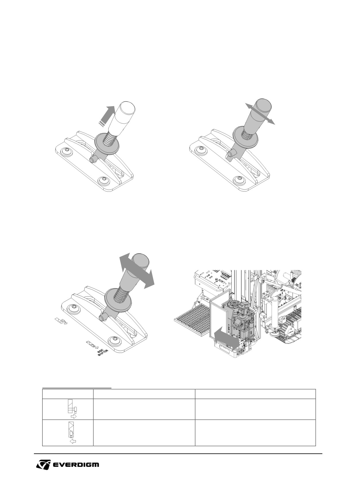
Safety levers
For safety reason, Some levers have self locking system on neutral position. To unlock the lever, pull
up the bottom plate with fingers until locking bar is released, then move lever for operation.
Figure: Unlocking safety lever and operation
Rotary head side shift
To add or remove pipe efficiently, move the rotary head from drilling position.
Figure: Side shift operation
Table: Side shift operation
Symbol
Description
Instruction
When lever is pushed, rotary head
Move rotary head to side position
moves to the side position.
Move rotary head to drilling
When lever is pulled, rotary head
position
moves to the drilling position.
100
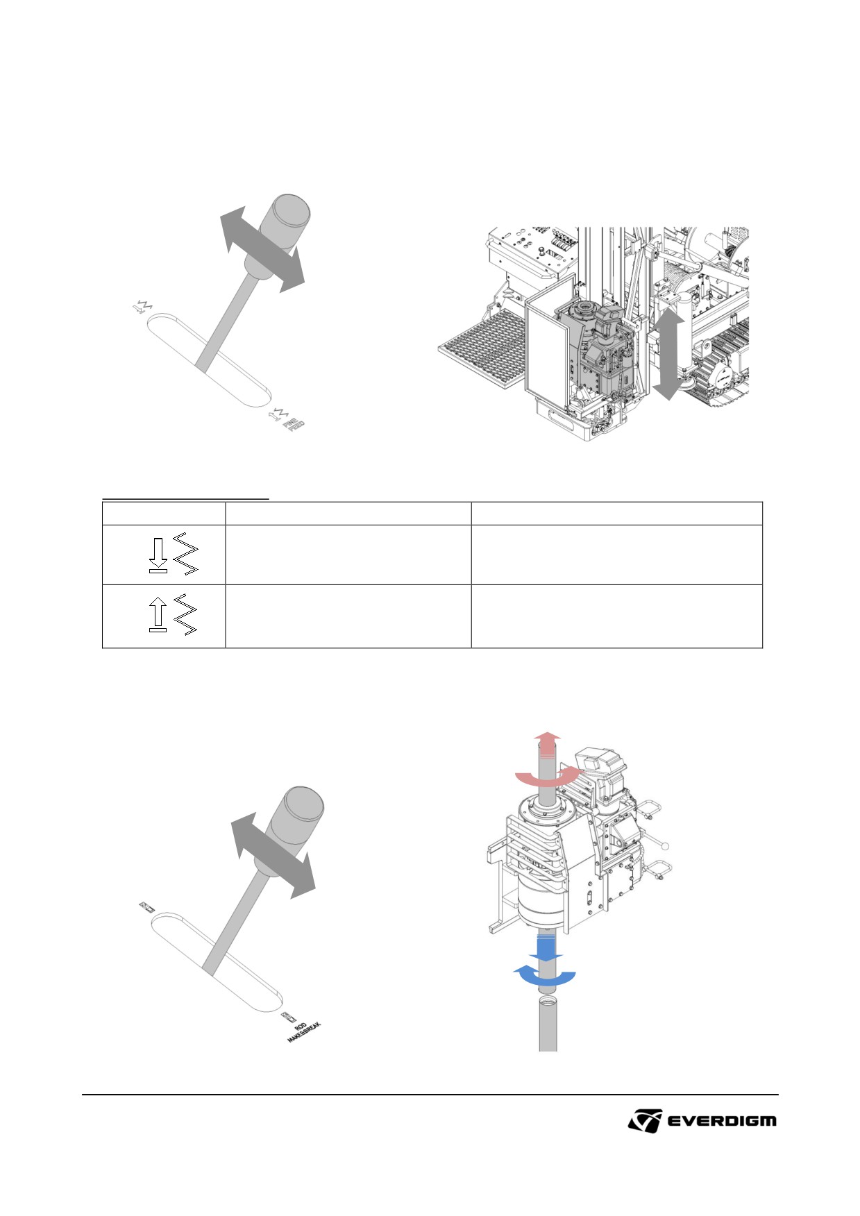
Fine feed
To precise and slow feed movement, operate fine feed during drilling.
Figure: Side shift operation
Table: Side shift operation
Symbol
Description
Instruction
Fine feed (Forward)
Slow feed to drilling forward
Fine feed (Backward)
Slow feed to backward.
Rod make and break
It control rotation feed speed of rotary head for connecting and disconnecting pipes
Figure: Rod make and break operation
101
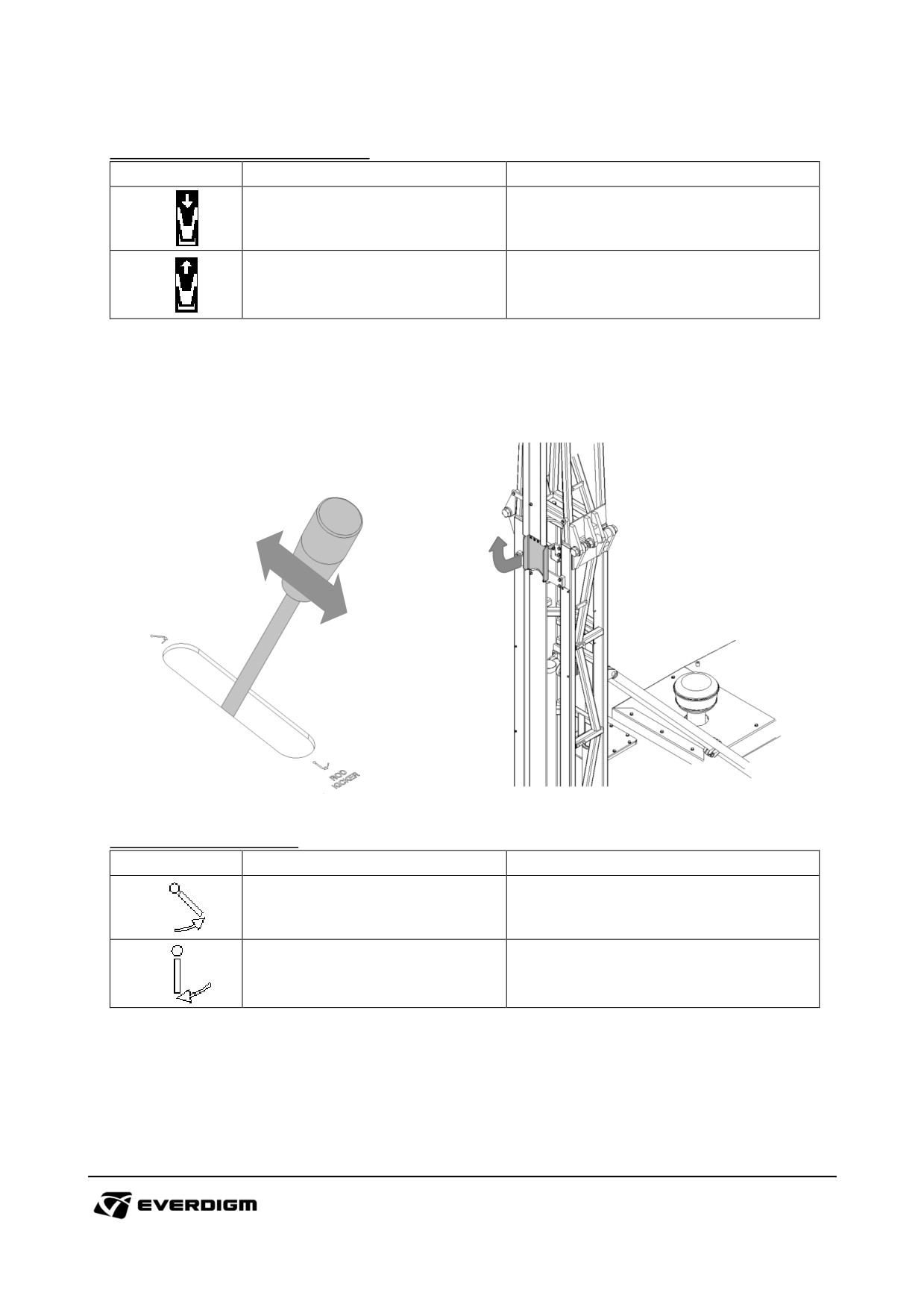
Table: Rod make and break operation
Symbol
Description
Instruction
Rod connect
Feed forward and normal rotation.
Feed backward and reverse
Rod disconnect
rotation.
Rod kicker
Rod kicker support pipe on the top side of mast.
Figure: Rod kicker operation
Table: Rod kicker operation
Symbol
Description
Instruction
Open rod kicker plate to support
Rod kicker open
pipe
Rod kicker fold
Fold rod kicker inside of mast.
102
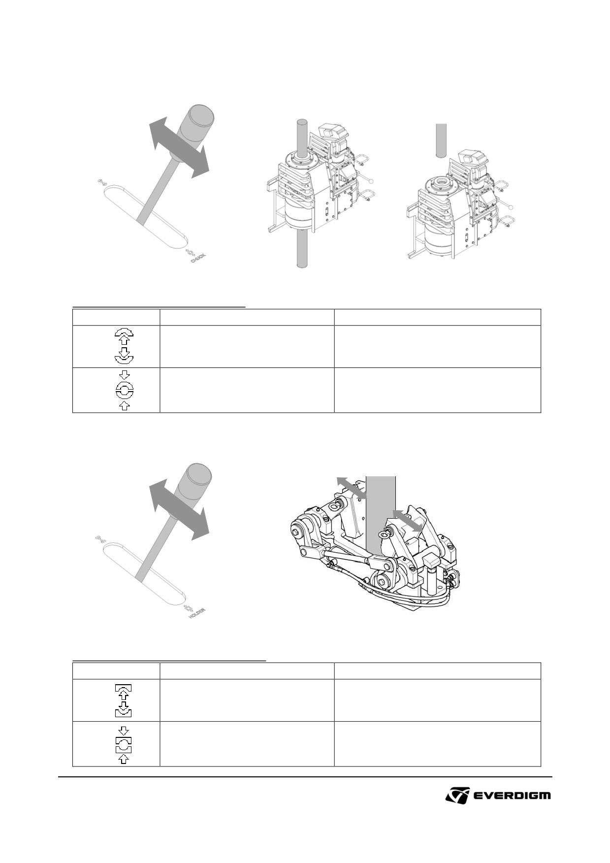
Chuck hold and release
Figure: Pipe hold and release by chuck
Table: Pipe hold and release by chuck
Symbol
Description
Instruction
Chuck open
Release pipe by opening chuck
Chuck close
Hold pipe by closing chuck
Foot clamp open and close
Figure: Pipe hold and release by foot clamp
Table: Pipe hold and release by foot clamp
Symbol
Description
Instruction
Foot clamp open
Release pipe by opening foot clamp
Foot clamp close
Hold pipe by closing foot clamp
103
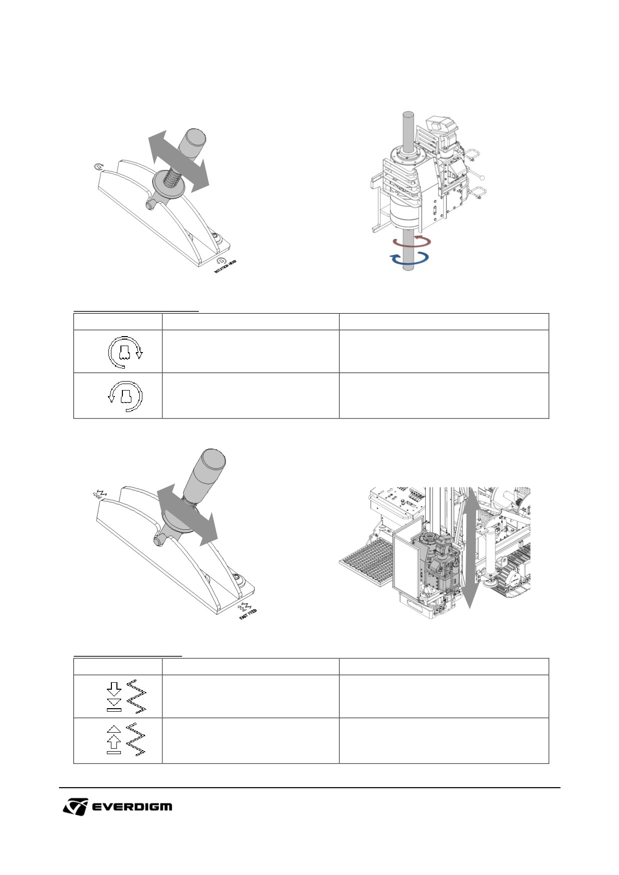
Rotary head rotation control
Figure: Rotary head rotation
Table: Rotary head rotation
Symbol
Description
Instruction
Normal rotation
Rotary head clockwise rotation
Rotary
head counterclockwise
Reverse rotation
rotation.
Fast feed control
Figure: Fast feed control
Table: Fast feed control
Symbol
Description
Instruction
Feed forward movement (with high
Fast feed forward
speed)
Feed backward movement
(with
Fast feed backward
high speed)
104
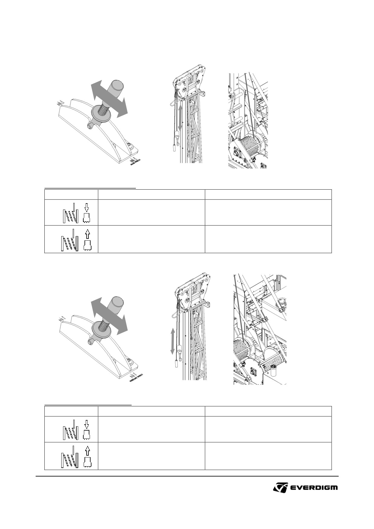
Main wire winch control
Figure: Main wire winch operation
Table: Main wire winch operation
Symbol
Description
Instruction
Main winch down
Drop main winch to down.
Main winch up
Lift main winch to up.
Wireline winch control
Figure: Wireline winch operation
Table: Wireline winch operation
Symbol
Description
Instruction
Wireline winch down
Drop Wireline winch to down.
Wireline winch up
Lift Wireline winch to up.
105
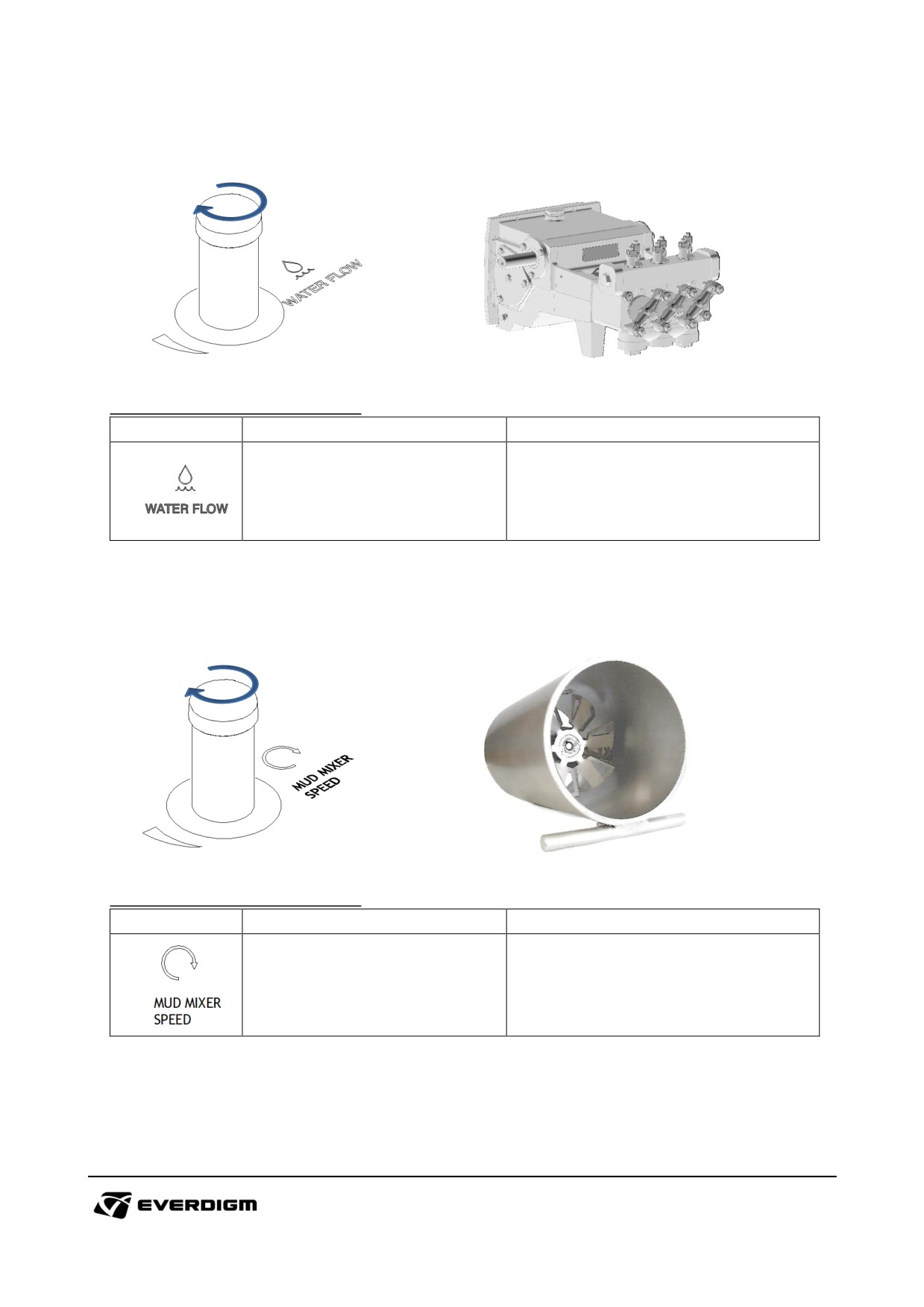
Water pump flow control knob
Figure: Water pump flow control knob
Table: Water pump flow control knob
Symbol
Description
Instruction
Rotate knob to clockwise :
Increase water flow.
Water flow amount control from
water pump
Rotate knob to counterclockwise :
Decrease water flow.
Mud mixer speed control knob
Figure: Water pump flow control knob
Table: Water pump flow control knob
Symbol
Description
Instruction
Rotate knob to clockwise :
Increase motor speed.
Mud mixer motor speed control
Rotate knob to counterclockwise :
Decrease motor speed.
106
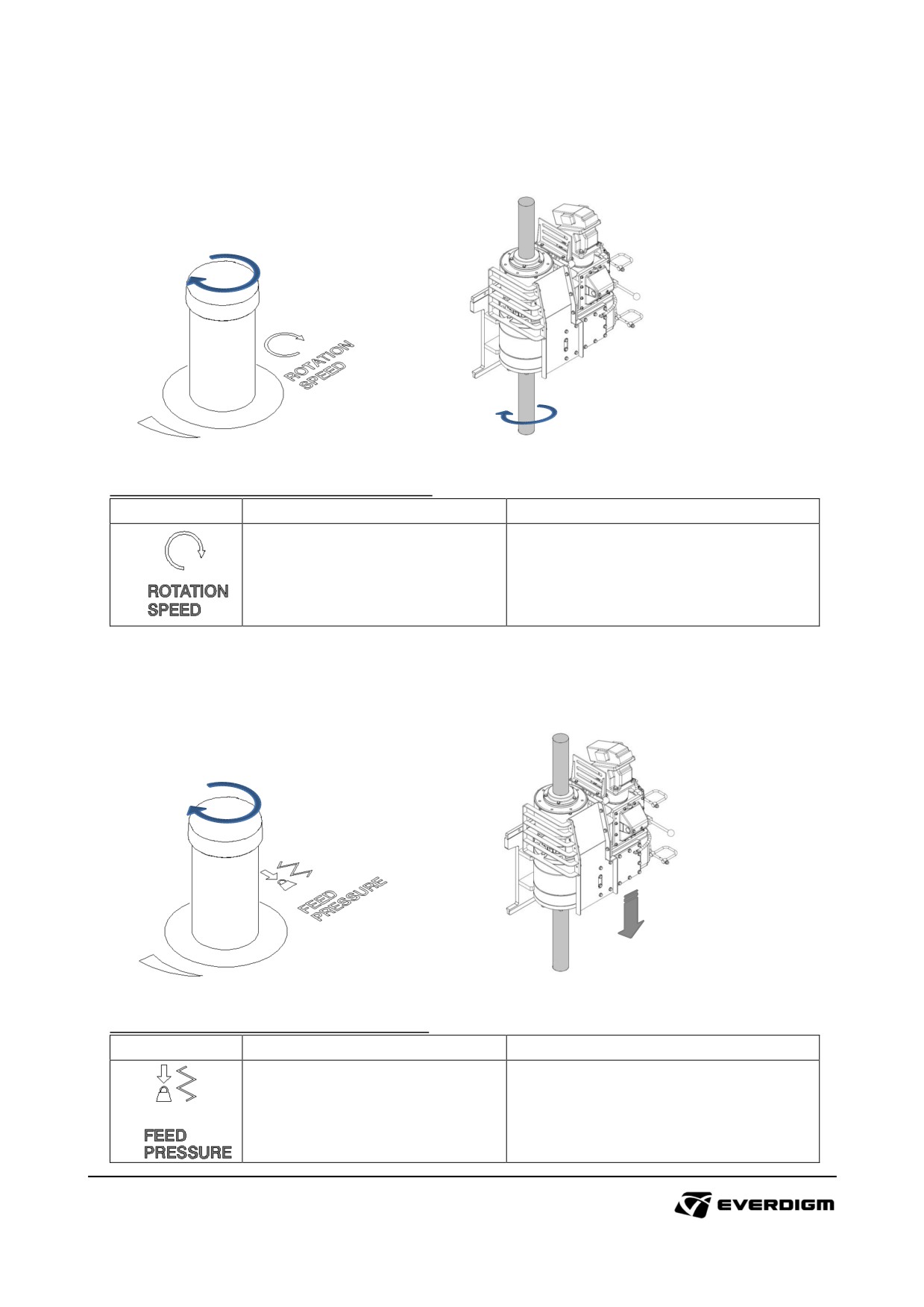
Rotary head rotation speed control knob
Figure: Rotary head rotation speed control knob
Table: Rotary head rotation speed control knob
Symbol
Description
Instruction
Rotate knob to clockwise :
Increase rotation speed.
Rotary head rotation speed
control
Rotate knob to counterclockwise :
Decrease rotation speed.
Feed pressure control knob
Figure: Rotary head feed pressure control knob
Table: Rotary head feed pressure control knob
Symbol
Description
Instruction
Rotate knob to clockwise :
Increase feed pressure.
Rotary head feed pressure
control
Rotate knob to counterclockwise :
Decrease feed pressure.
107
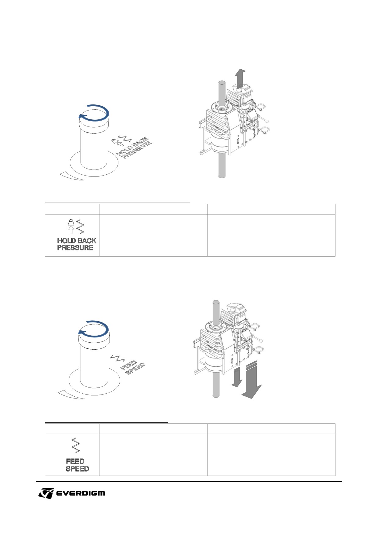
Hold back pressure control knob
Figure: Rotary head hold back pressure control knob
Table: Rotary head hold back pressure control knob
Symbol
Description
Instruction
Rotate knob to clockwise :
Increase hold back pressure.
Rotary head hold back pressure
control
Rotate knob to counterclockwise :
Decrease hold back pressure.
Feed speed control knob
Figure: Rotary head feed speed control knob
Table: Rotary head feed speed control knob
Symbol
Description
Instruction
Rotate knob to clockwise :
Decrease feed speed.
Rotary head feed speed control
Rotate knob to counterclockwise :
Increase feed speed.
108
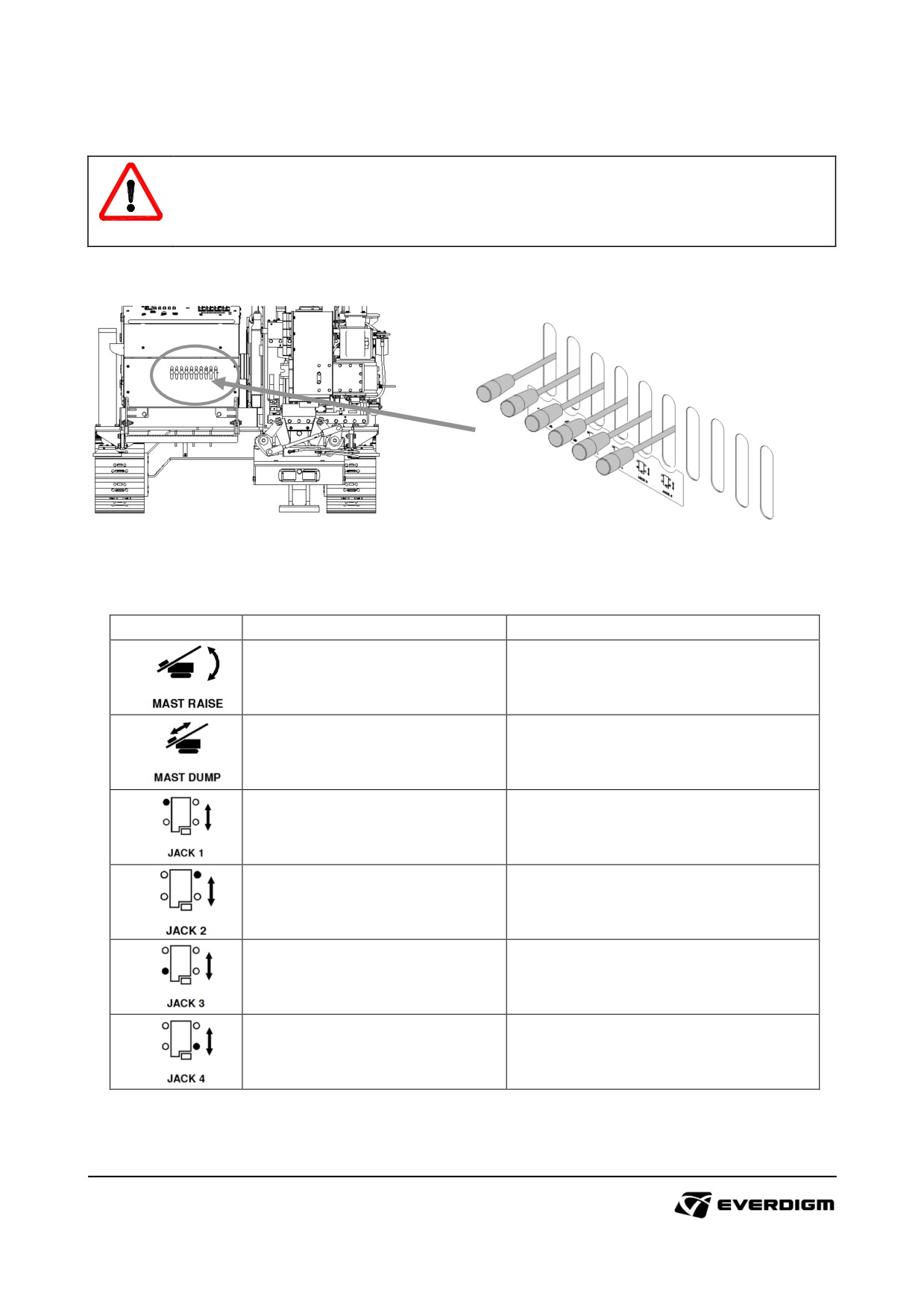
4.5.3 Mast positioning and outrigger operation levers
WARNING!
Check all obstacles before operating mast and outrigger. Clear the area where mast and
outrigger will be located.
Figure: Mast and outrigger operating levers
Table: Mast and outrigger operating levers
Symbol
Description
Instruction
Mast raise lever
Mast lift up or down movement
Mast forward or backward
Mast dump lever
movement
Outrigger raise up or down
Outrigger operation lever 1
operation
Outrigger raise up or down
Outrigger operation lever 2
operation
Outrigger raise up or down
Outrigger operation lever 3
operation
Outrigger raise up or down
Outrigger operation lever 4
operation
109
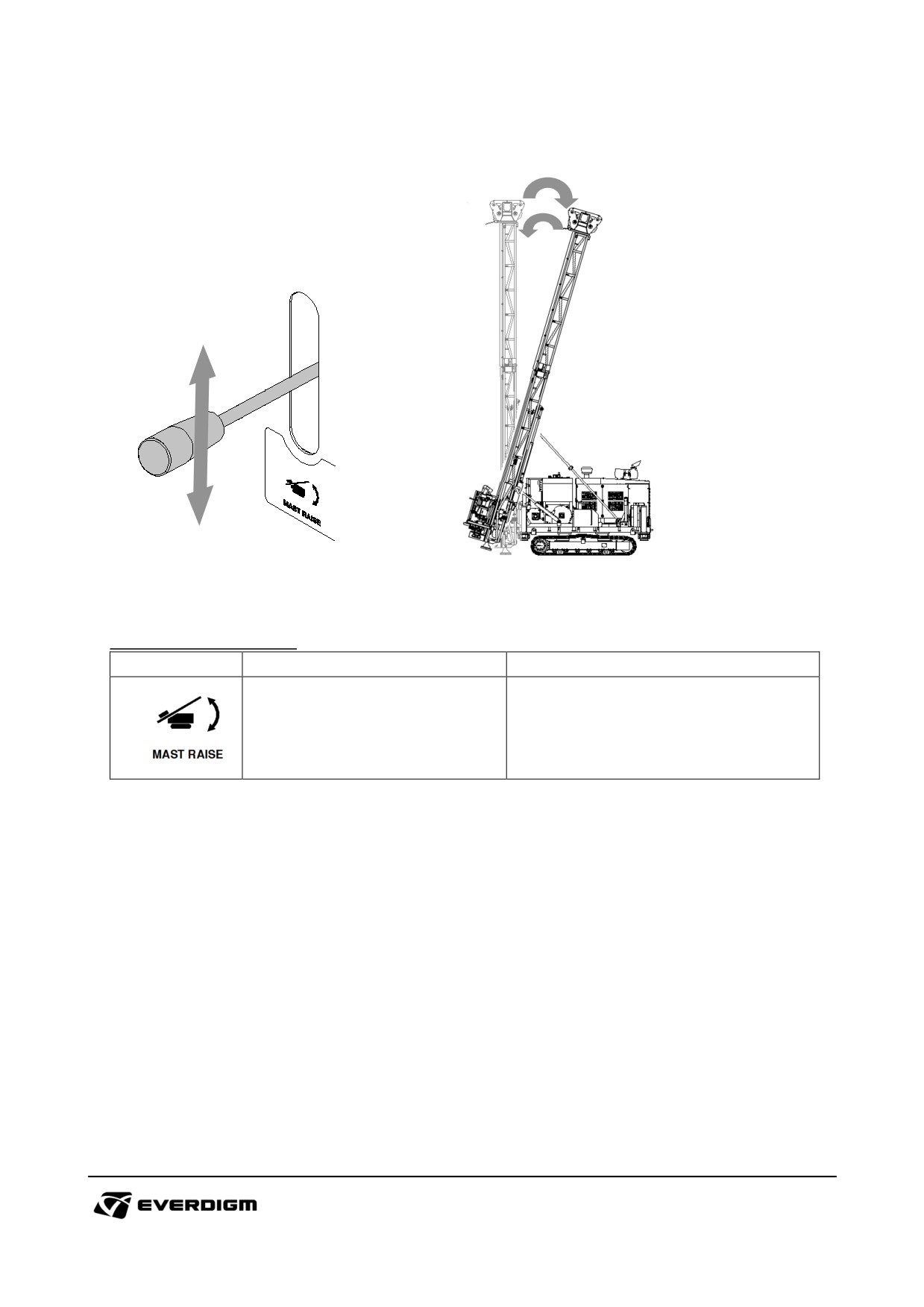
Mast raise operation
Figure: Mast raise operation
Table: Mast raise operation
Symbol
Description
Instruction
Lever up
:
Mast raise up.
Mast raise up or lay down
movement
Lever down :
Mast lay down
110
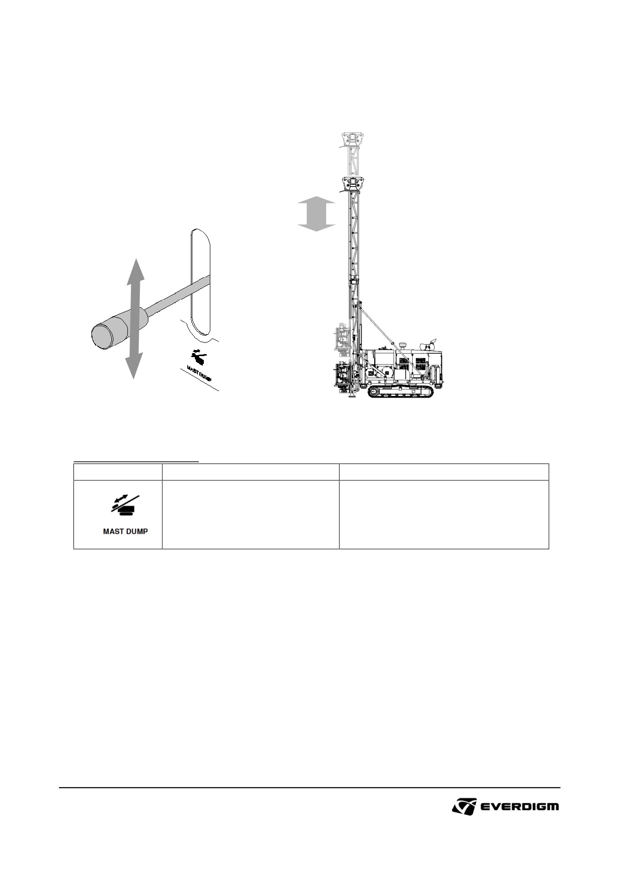
Mast dump operation
Figure: Mast dump operation
Table: Mast raise operation
Symbol
Description
Instruction
Lever up
:
Mast moves backward.
Mast forward or backward
movement
Lever down :
Mast moves forward.
111
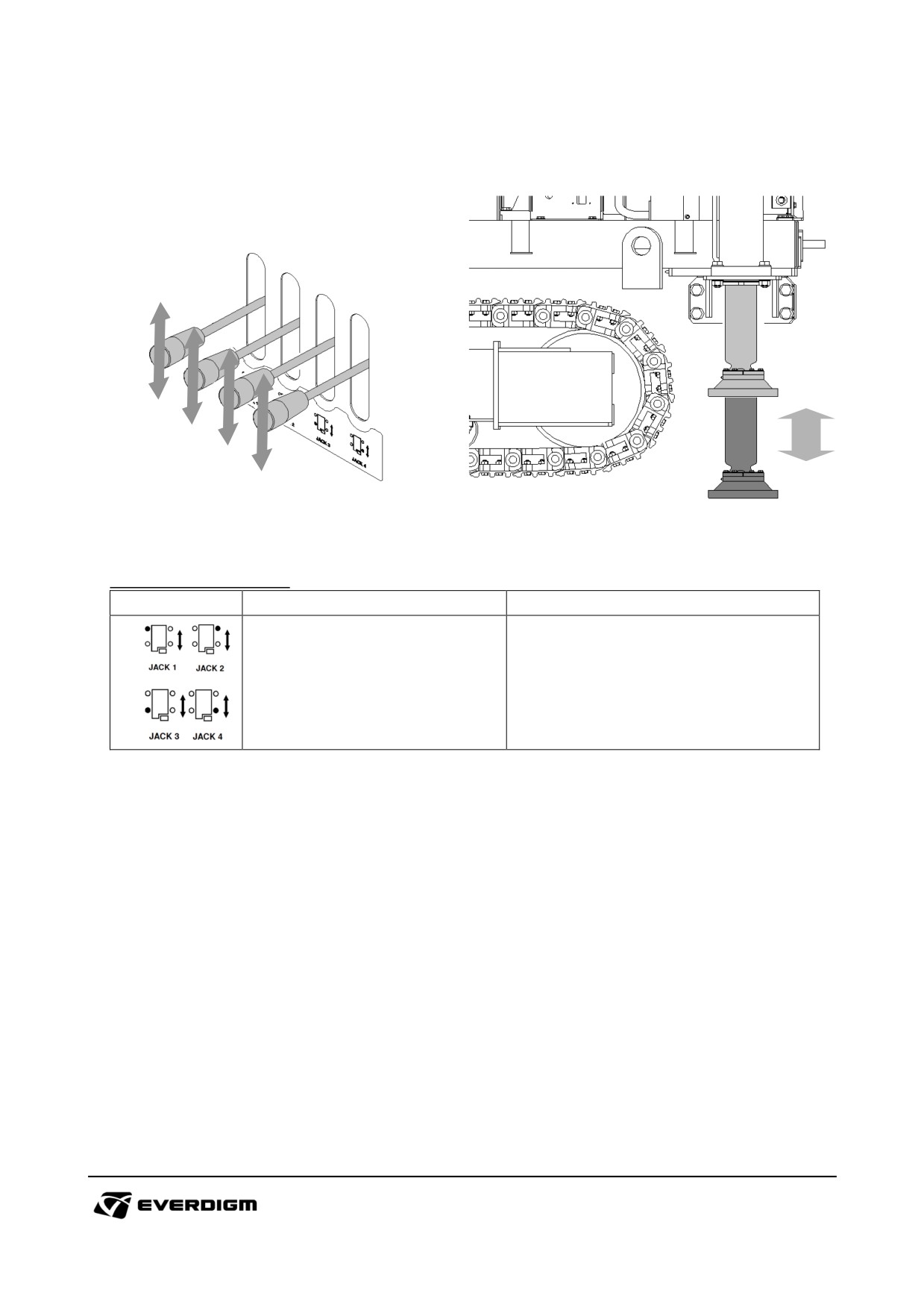
Outrigger operation
Figure: Outrigger operation
Table: Outrigger operation
Symbol
Description
Instruction
Lever up
:
Outrigger fold.
Outrigger operation
Lever down :
Outrigger extend.
112
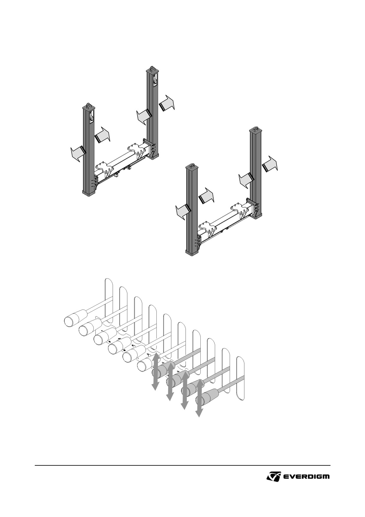
Extendable outrigger operation levers (Option)
Figure: Extendable outrigger operation
Figure: Extendable outrigger operation lever (Option)
Extending or folding outriggers by operating levers. Outriggers operation is done separately by each
levers.
113
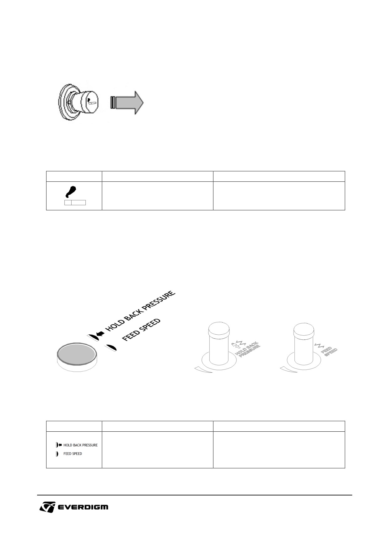
Cigar jack
Heat up cigar jack, or power connection for electric devices.
Figure: Cigar jack
Table: Cigar jack
Symbol
Parts
Instruction
Push : Heat up
Cigar jack
Pull out : Removal and disconnect
Note:
Before connecting electric device on cigar jack, check the rated capacity of the device and connector.
Hold back pressure / Feed speed control selection switch
During drilling, the Feed speed control / Hold back pressure can be switched .
Figure: Hold back pressure / Feed speed control selection switch
Table: Hold back pressure / Feed speed control selection switch
Symbol
Parts
Instruction
Pushed :
Hold back pressure / Feed speed
Hold back pressure activated
control selection switch
Pulled out :
Feed speed activated.
Note:
For more detail of use, refer to Chap. "4.6.7 Hold back pressure operation" section..
114
4.6. Drilling
DANGER!
Never approach rotary head, engine, wire line drums, pipe, bit and drilling area while machine
is operating.
Some parts may extremely hot. Do not touch hot components with bare hands until it is
cooled.
4.6.1 Caution for rotary operation
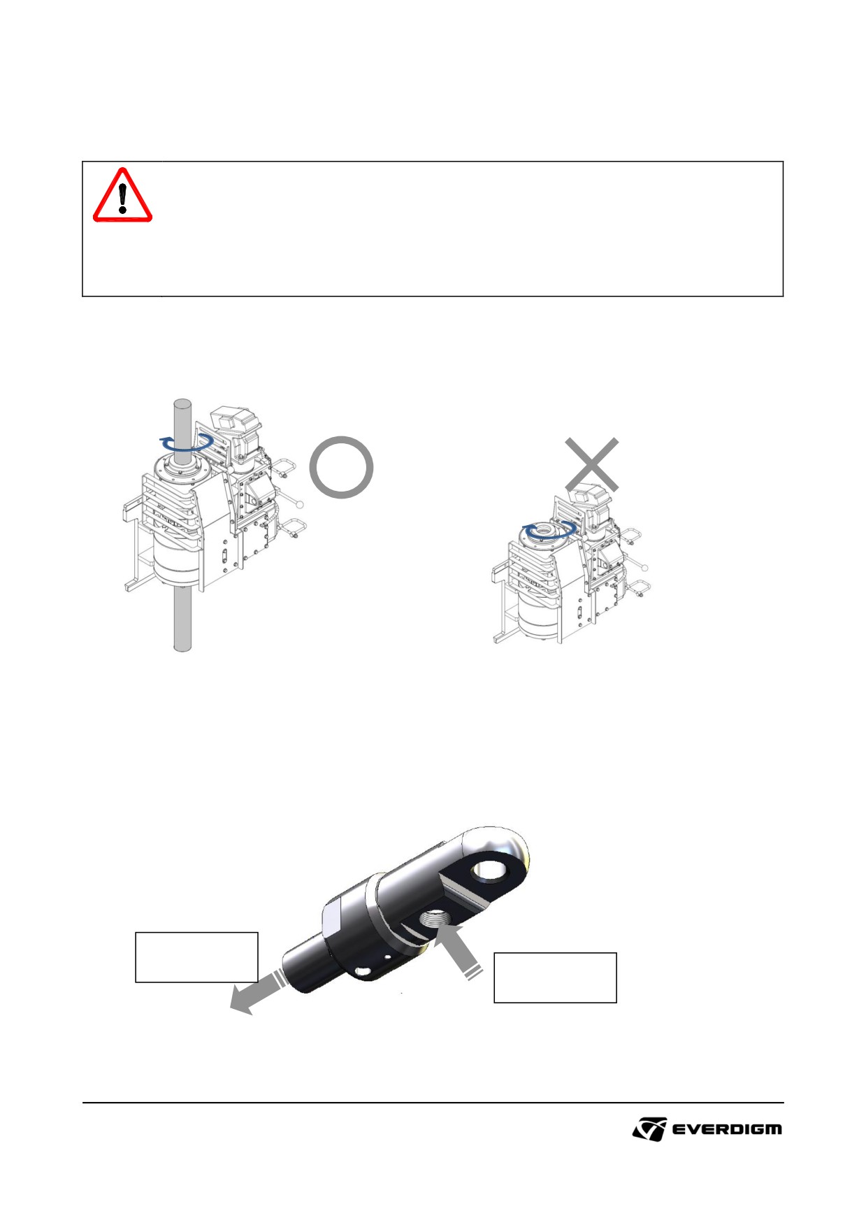
Do not operate rotary head without holding pipe
Rotary head operation without holding pipe will cause serious damage on the chuck and related parts.
4.6.2 Preparation of water swivel
Connect water swivel with pipe and water hose
Connecting with
pipe
Connecting with
water hose
Prepare water swivel to supply water to pipe and bit.
115
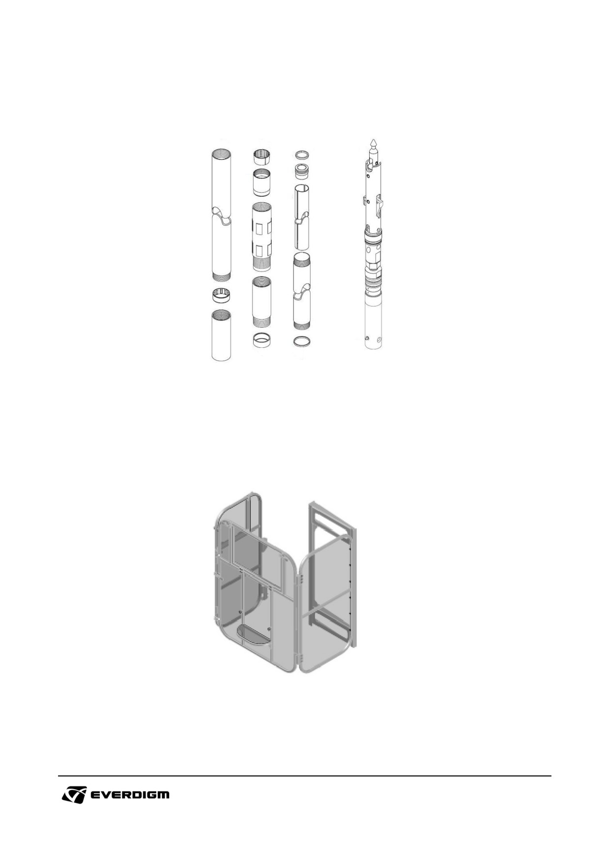
4.6.3 Preparation of core barrel
To collect core sample, prepare core barrel and put it on the pipe. Check core barrel, inner pipe and
components carefully. Bent or damaged parts should be replaced with new one.
4.6.4 Spin cage locking condition check
For safety measure, some operation can not be performed if spin cage gate is opened. Check
approximate sensor on the gate, and working condition of rotary head when the gate is closed.
116
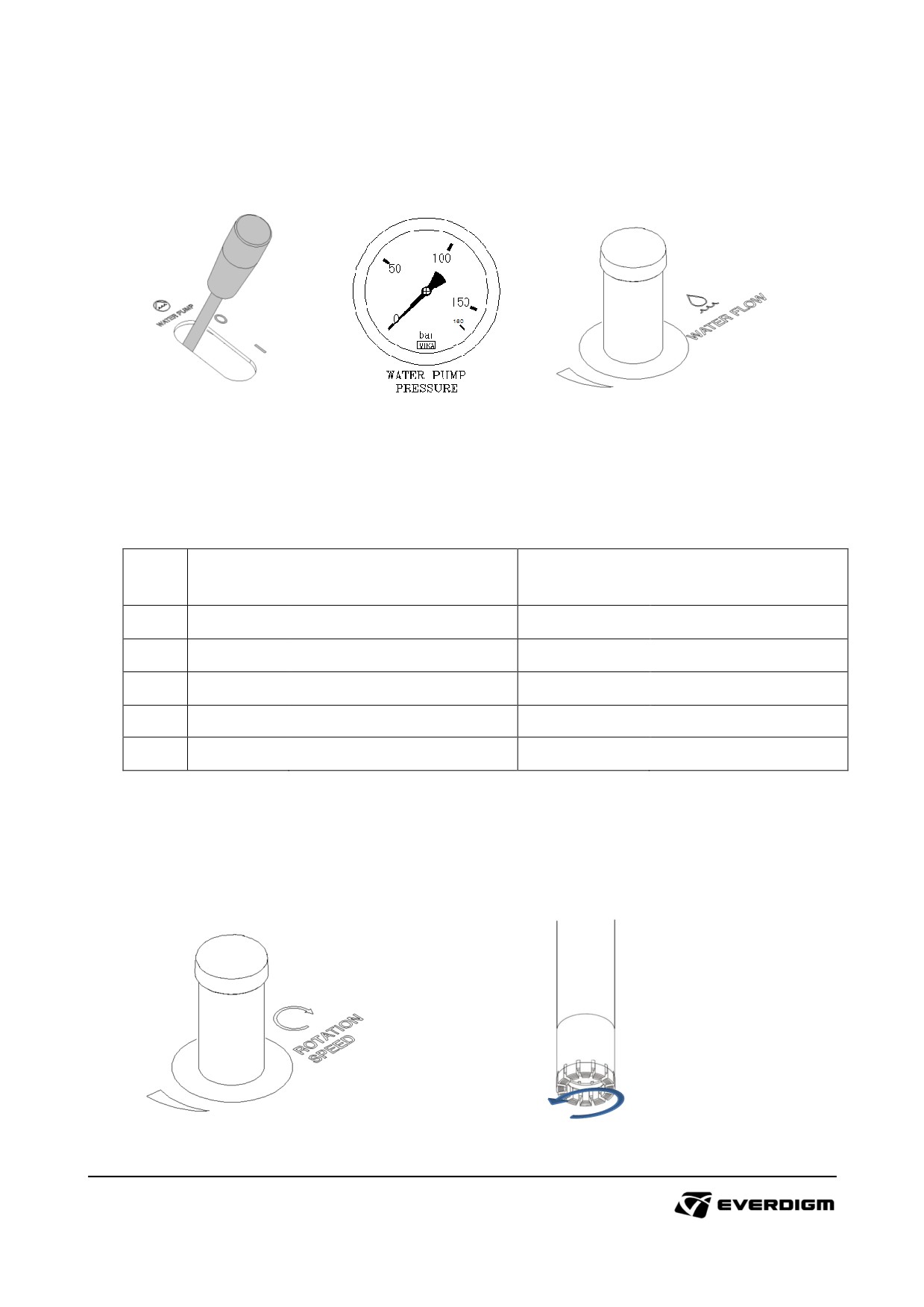
4.6.5 Before drilling
① Start water pump by operation lever, and check water pressure and adjust output water amount.
② Check water leakage from hose, fittings and swivel.
4.6.6 Start rotary head operation.
① Determined the rotation speed and torque according to ground condition and pipe size.
Trans
ECR12
ECR18
mission
Step
Speed, RPM
Torque, Nm (lb·ft)
Speed, RPM
Torque, Nm (lb·ft)
1
134 - 189
4,155 - 2,947 (3,064 - 2,173)
128 - 178
5,541 - 3,990 (4,086 - 2,942)
2
303 - 426
1,847 - 1,310 (1,362 - 966)
288 - 400
2,462 - 1,774 (1,815 - 1,308)
3
538 - 758
1,039 - 737 (766 - 564)
511 - 711
1,385 - 998 (1,021 - 736)
4
968 - 1,364
577 - 409 (425 - 313)
920 - 1,200
700 - 554 (567 - 408)
Chart: Rotary head RPM and Torque according to Transmission setting
② Open foot clamp and operate rotary head.
③ Adjust the bit rotation speed with rotation speed control knob.
117
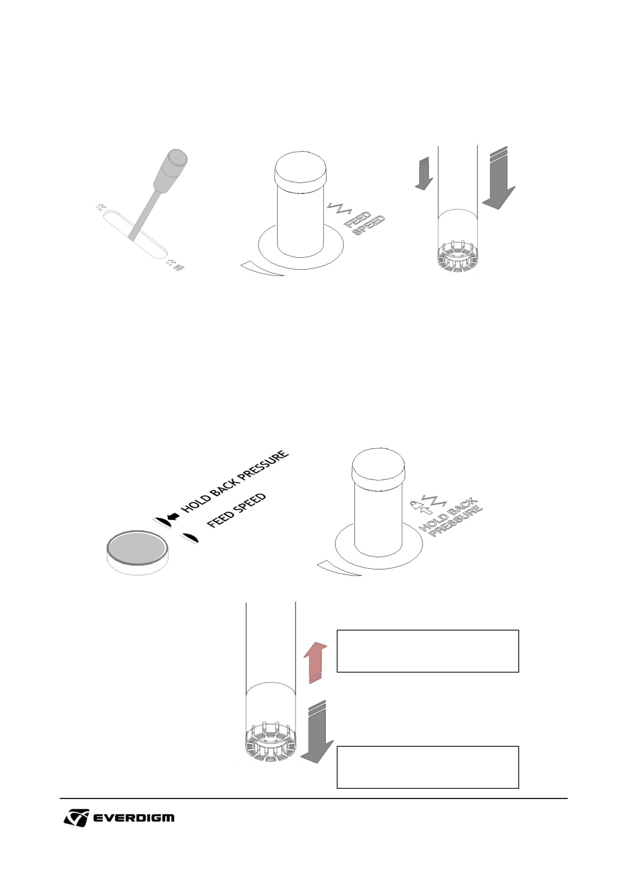
4.6.7 Starting fine feed
① Start find feed with operation lever, and adjust feed speed with feed speed control knob.
② Adjust feed pressure and speed with knobs. Too much feed pressure and speed may cause the bit
early wear or damage.
4.6.8 Hold back pressure operation
① When drilled hole is deep, the weight of accumulated pipe is naturally makes feed force. Under this
condition, the backward force on the feed is required to support drilling on the bit. To balance feed
force, operate and control hold back pressure
Select 'Hold back pressure' mode by pushing switch, and adjust hold back pressure with control knob.
To balance down feed force, hold back
pressure is required.
Force is naturally applied on the bit by
pipes weight
118
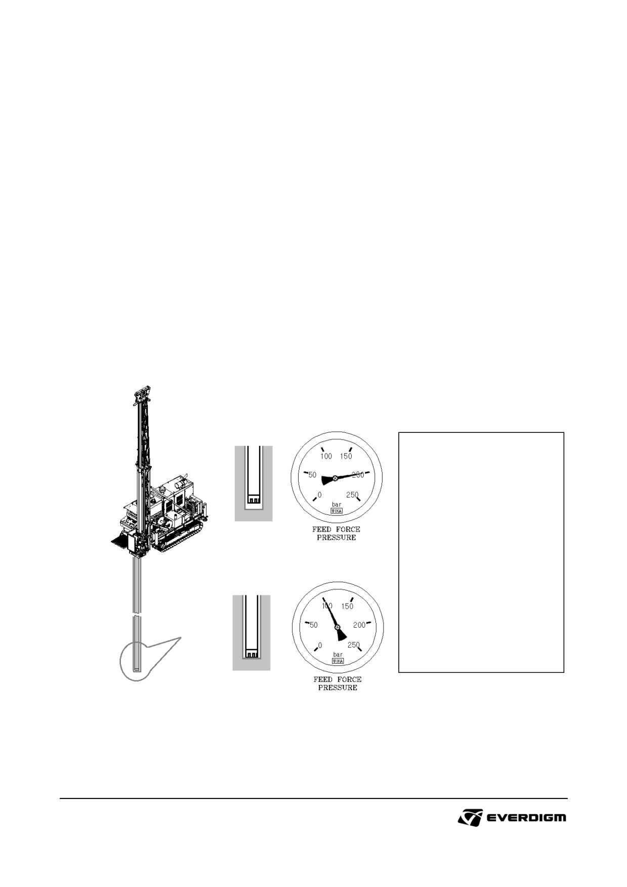
4.6.9 Understanding on the OFF Pressure and Down ward force on Bit
WOB (Weight On Bit, downward force on bit)
The force on the bit is approximately equal to the weight of pipe and feed force. Actual WOB can not
be measured, however it can be calculated by OFF Pressure method as described below.
Off Pressure measuring
(1) After adding the pipe, operate normal rotation of rotary head and fine feed forward.
Before the bit contacting on the ground, see the 'Feed force pressure' gauge.
(2) When the bit is contacting on the bottom of drilled hole and start drilling, read the 'Feed force
pressure' on the gauge.
(3) Then, calculate the actual decreased pressure difference as shown below.
* Measured feed force pressure before contacting bit with ground : A
* Measured feed force pressure when bit is contacting with ground : B
* Off pressure = A - B
* After calculating Off pressure, refer to the following chart to see the actual WOB (downward force
on the bit)
* Model : ECR18
* Feed force pressure before
contacting ground with bit :
200 BAR
* Feed force pressure after
contacting ground with bit :
100 BAR
* Off Pressure : 100 bar
* WOB (Weight On Bit,
Downward force on bit) :
9,530 kg
Example: Off Pressure calculation
* WOB (or Downward force on bit) calculation (kg base)
- ECR12 : Off pressure (BAR) x 63.62
- ECR18 : Off pressure (BAR) x 95.03
119
ECR12
Off Pressure
Downward Force on Bit
Off Pressure
Downward Force on Bit
BAR
PSI
kg
Lbf
BAR
PSI
kg
Lbf
5
73
318
701
105
1,523
6,680
14,726
10
145
636
1,403
110
1,595
6,998
15,428
15
218
954
2,104
115
1,668
7,316
16,129
20
290
1,272
2,805
120
1,740
7,634
16,830
25
363
1,590
3,506
125
1,813
7,952
17,532
30
435
1,909
4,208
130
1,885
8,270
18,233
35
508
2,227
4,909
135
1,958
8,588
18,934
40
580
2,545
5,610
140
2,030
8,906
19,635
45
653
2,863
6,311
145
2,103
9,225
20,337
50
725
3,181
7,013
150
2,175
9,543
21,038
55
798
3,499
7,714
155
2,248
9,861
21,739
60
870
3,817
8,415
160
2,321
10,179
22,440
65
943
4,135
9,116
165
2,393
10,497
23,142
70
1,015
4,453
9,818
170
2,466
10,815
23,843
75
1,088
4,771
10,519
175
2,538
11,133
24,544
80
1,160
5,089
11,220
180
2,611
11,451
25,245
85
1,233
5,407
11,921
185
2,683
11,769
25,947
90
1,305
5,726
12,623
190
2,756
12,087
26,648
95
1,378
6,044
13,324
195
2,828
12,405
27,349
100
1,450
6,362
14,025
200
2,901
12,723
28,050
Chart: ECR12 Off Pressure and Downward force on bit
ECR18
Off Pressure
Downward Force on Bit
Off Pressure
Downward Force on Bit
BAR
PSI
kg
Lbf
BAR
PSI
kg
Lbf
5
73
475
1,048
105
1,523
9,978
21,999
10
145
950
2,095
110
1,595
10,454
23,046
15
218
1,425
3,143
115
1,668
10,929
24,094
20
290
1,901
4,190
120
1,740
11,404
25,141
25
363
2,376
5,238
125
1,813
11,879
26,189
30
435
2,851
6,285
130
1,885
12,354
27,237
35
508
3,326
7,333
135
1,958
12,829
28,284
40
580
3,801
8,380
140
2,030
13,305
29,332
45
653
4,276
9,428
145
2,103
13,780
30,379
50
725
4,752
10,476
150
2,175
14,255
31,427
55
798
5,227
11,523
155
2,248
14,730
32,474
60
870
5,702
12,571
160
2,321
15,205
33,522
65
943
6,177
13,618
165
2,393
15,680
34,570
70
1,015
6,652
14,666
170
2,466
16,156
35,617
75
1,088
7,127
15,713
175
2,538
16,631
36,665
80
1,160
7,603
16,761
180
2,611
17,106
37,712
85
1,233
8,078
17,809
185
2,683
17,581
38,760
90
1,305
8,553
18,856
190
2,756
18,056
39,807
95
1,378
9,028
19,904
195
2,828
18,531
40,855
100
1,450
9,503
20,951
200
2,901
19,007
41,902
Chart: ECR18Off Pressure and Downward force on bit
120
4.6.10 Stop drilling operation
① Stop fine feed by put the fine feed operation lever on neutral position.
② Stop rotation of rotary head by put the rotary head operation lever on neutral position.
③ It is recommended to flush the drill hole for some minutes after stopping drilling to avoid problems
from cuttings and sludge.
4.6.11 Wireline operation and collecting sample
① Operate wireline lever, and put the wire to catch the core barrel.
② After catching the core barrel, and pull out the wire with wireline lever operation.
IMPORTANT!
Do not stop wireline winch suddenly. Otherwise, it may cause a jump and core barrel
locking will loose the grip, then it can be fallen inside of hole.
4.6.12 Adding and connecting the pipe
① Lift up a pipe with main wire winch, and put it inside of rotary head.
② Grab the pipe with rotary head chuck and move it until it reaches on the pipe which grab by foot clamp.
③ Use 'rod make' operation to connect pipes
④ If requires, use pipe wrench when pipe is adding or removing.
Figure: Pipe wrench
4.6.13 Removing and disconnecting the pipe
① Connect upper pipe with main winch, and lift up a pipe and hold bottom pipe with foot clamp.
② Disconnecting pipes with 'rod break' operation.
③ After disconnecting the pipe, remove upper pipe by using main winch operation.
121
5. Maintenance
DANGER!
Do not operate machine during maintenance.
Some parts may be very hot. Do not touch parts until they are cooled down.
Wear safety glove, helmet, glass and mask for personal safety.
WARNING!
Put safety sticker or warning tag and alert to others if maintenance of machine is not finished.
Observe maintenance schedule as describes in this manual. If you have doubt on
maintenance method, contact to Everdigm official distributor.
The failure resulted from the lack of maintenance will not be covered by warranty.
During the maintenance of electric devices, turn off master key and remove batteries in
advance.
Some parts are might be pressurized by hydraulic or air. Depressure the components before
maintenance. Please note that some parts may fall when pressure is falling.
IMPORTANT!
It is recommended putting the maintenance record.
Clean equipment and remove rock powder and dust before maintenance. Dust will cause
wear of moving parts, troubles on hydraulic components and blockage of air intake and
cooling system.
For environment protection, prepare empty bottle and oil cleaning papers. Drained liquid, oil
and grease from the machine should be disposed according to environmental regulation.
Register the engine warranty to official engine service which is located nearest by machine.
Engine warranty registration should be done before 200 engine hour on tachometer.
Use only genuine Everdigm parts.
Use recommended oils and grease. Do not mix oil.
Use high grade diesel which is recommended by engine manufacturers.
122
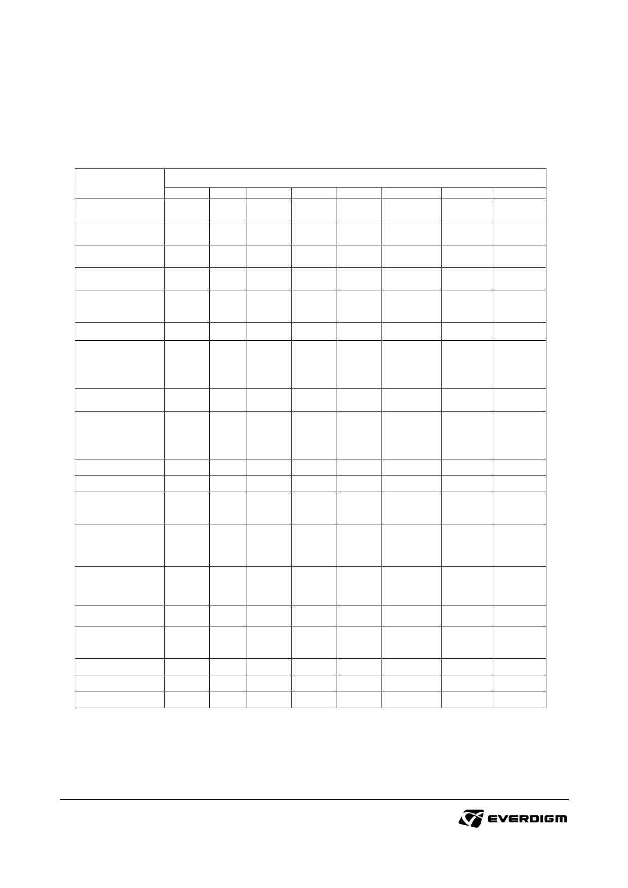
5.1. Maintenance schedule
5.1.1 Engine and related parts
O: Check ◎: Clean ◆: Lubricate ◈: Replace
Compartment or
Maintenance interval (Every)
System
Daily
50H
200H
250H
500H
1000H
1500H
2000H
Engine oil
1)◈
◈
Engine oil filters
1)◈
◈
Fuel level
O
Fuel leakage
O
Fuel·water
1)◈
◈
separator filter
Fuel filters
1)◈
◈
Drain of water
from fuel tank and
O
◎
separator.
Breather filter
◈
Leakage and
contamination of
O
◎
◈
Coolant
Fins on radiator
◎
Engine belt
O
Intercooler and
O
hose
Air cleaner
O
indicator
Air suction line
O
and connector
Main battery
O
Wiring and
O
connector
Primary air filter
O
2)◎
Secondary air filter
O
2)◎
◈
Centerflex
O
◈
*1) First replacement period
* 2) Daily check, clean if it blocked. Damaged filters should be replaced immediately.
123
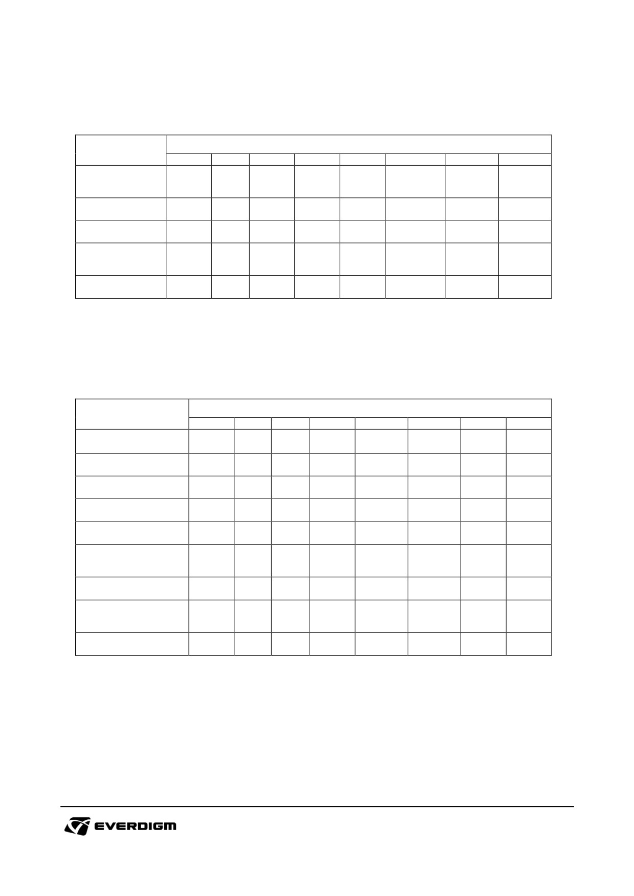
5.1.2 Track
O: Check ◎: Clean ◆: Lubricate ◈: Replace
Compartment or
Maintenance interval (Every)
System
Daily
50H
200H
250H
500H
1000H
2000H
4000H
Tension of track
O
shoe
Oil leakage
O
Motor gear oil
1)◈
◈
Wear of roller and
O
idler
Bolts loosening
O
*1) First replacement period
5.1.3 Hydraulic oil
O: Check ◎: Clean ◆: Lubricate ◈: Replace
Compartment or
Maintenance interval (Every)
System
Daily
50H
200H
250H
600H
1200H
1800H
2400H
Hydraulic oil
O
1)◈
◈
Cooler fan
◎
Hydraulic oil tank
◎
Return filter
1)◈
3)◈
Air breather
O
◈
Suction hose and
O
◎
connector
Suction filter
◈
Drain of water from
O
hydraulic oil tank
High Pressure Filter
◈
*1) First replacement period
*3) It needs to be change one time as indicated above table. It can be changed according to installed filter condition.
Check it when oil is replaced.
124
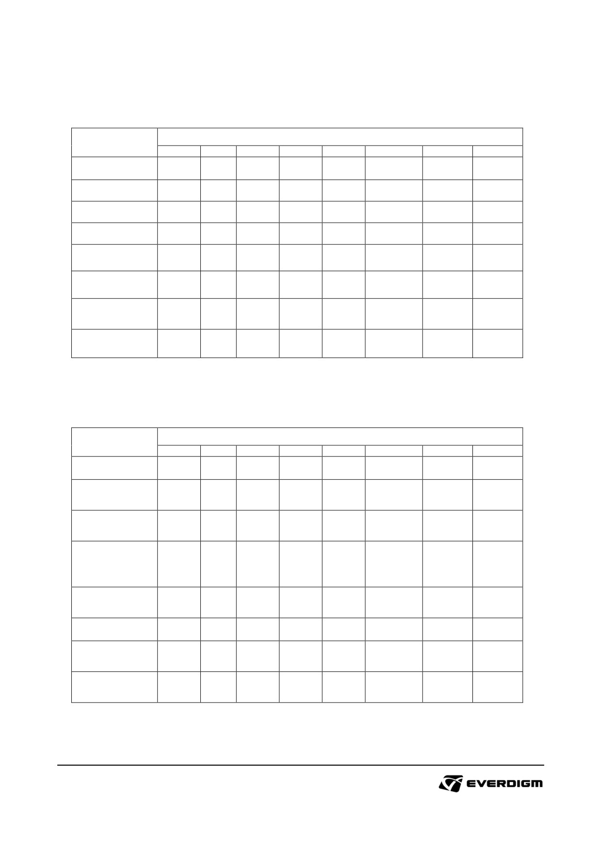
5.1.4 Rotary head
O: Check ◎: Clean ◆: Lubricate ◈: Replace
Compartment or
Maintenance interval (Every)
System
Daily
50H
200H
250H
500H
1000H
1500H
2000H
Gear box
O
Strainer filter
◎
Gear oil
◈
Oil filter
◈
Jaw on the chuck
◆
◎
Chuck ball bearing
◆
Rotary head
O
◆
cradle
Side Shift
◆
◈
5.1.5 Mast and foot clamp
O: Check ◎: Clean ◆: Lubricate ◈: Replace
Compartment or
Maintenance interval (Every)
System
Daily
50H
200H
250H
500H
1000H
2000H
4000H
Oil leakage
O
Bolts, nuts and
O
fittings
Crack, bent,
O
damages
Grease supply on
moving parts (Pin
◆
and bushes)
Upper crown
◆
pulley
Foot clamp jaw
◎
Foot clamp
O
◈
cylinder
Hose and
O
connector
125
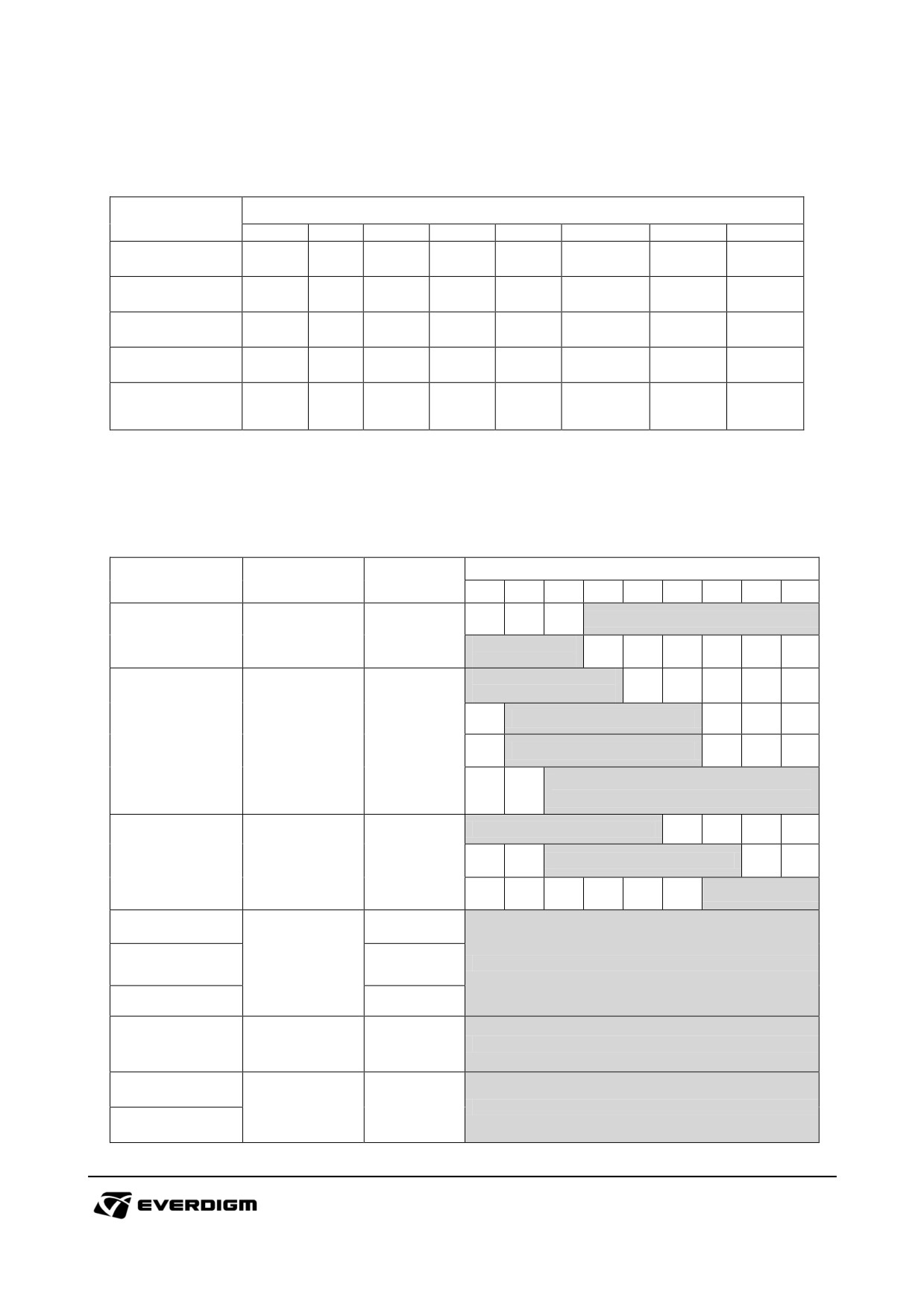
5.1.6 Wire winch
O: Check ◎: Clean ◆: Lubricate ◈: Replace
Compartment or
Maintenance interval (Every)
System
Daily
50H
200H
250H
500H
1000H
2000H
4000H
Main winch
◆
Wire line winch
◆
Main wire
O
◆
Wireline wire
O
◆
Main winch
1)◈
◈
motor oil
*1) First replacement period
5.2. Oils, lubricants and coolant
5.2.1 Specification of oils and lubricants
Compartment or
Category and
Ambient Temperature (℃)
Quantity
System
Classification
-30
-20
-10
0
10
20
30
40
50
No.2-D
Fuel Tank
Diesel
250 liter
No.1-D or
No.2-D
SAE 0W30
(-38~0℃)
SAE 5W30(-28~22℃)
Engine oil
Engine oil
API
18.9 litter
SAE 10W30(-22~22℃)
CH-4 or CI-4
SAE 0W40, SAE 5W40,
SAE 15W40(-15~55℃)
ISO VG32
Hydraulic Tank
Hydraulic oil
320 liter
ISO VG46
ISO VG 68
Rotary head
15 Liter
Gear oil,
Main winch motor
API
1.8 Liter
SAE 90
GL-4 or GL-5
Travel motor
1.3 Liter
Grease nipples
Grease EP
-
NLGI No. 2
Main winch wire
Brilube
Brilube 20 or Brilube 35
Wire line wire
Table: Specification of oils and lubricants
126
5.2.2 Coolant
DANGER!
Coolant contains toxic chemical. If you drink coolant by accident, throw up immediately, and
consult doctor right away.
If coolant get into eyes, clean it with purified water and consult doctor immediately.
Coolant may hot after running machine. Before maintenance of coolant, cool down system first
of all.
IMPORTANT!
Do not mix different coolant in radiator.
Use coolant water only. Mineral or normal water will cause corrosion and blockage of cooling
system.
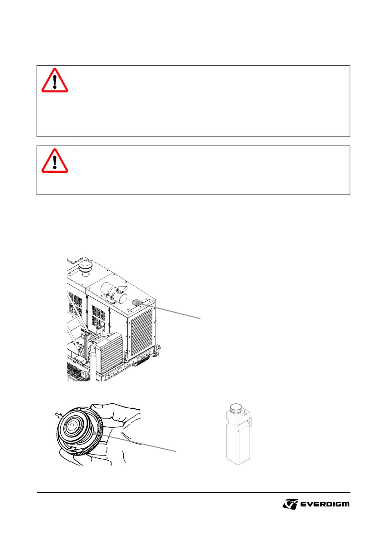
Check amount of coolant on radiator, and refill coolant. Open cover plate (marked "1") and open
radiator cap (marked "2"). Check sealing condition and spring on the cap.
For refill coolant, mix coolant water 50% and antifreeze 50% ratio. Hot or cold climate countries, check
the description of antifreeze and mix coolant according to antifreeze manufacturer recommendation.
1
Figure: Coolant inlet location
2
Figure: Radiator cap
Figure: Reservoir tank
127
5.3. Storage
IMPORTANT!
Improper storage condition may cause corrosion of components and machine.
When machine is likely to be stored more than 2 weeks, it is highly recommend following the guideline
below.
Preparation for machine storage
- Inspect machine and components of worn out and damaged parts thoroughly.
Replace new parts before storage.
- Remove all dusts and dried grease on the components.
- After washing machine, dry all components completely.
- Repaint area where paint peeled out. Put new safety sticker if it is lost or hard to read.
- Put the machine in door where has well ventilation and dry condition, and set the mast with parking
posture.
- Put grease on every lubrication points
- Spray anti rust fluid all around the machine and components.
- Check winding condition of wire inside of winch. Rewind wires and put oil or grease to prevent rust.
- Turn off master switch, and disconnect battery from machine.
- If machine will be stored outdoor storage area, machine should be covered with roof with good
ventilation.
- It is not recommended if machine is stored nearby sea shore.
Before operating machine after long term storage, it is highly recommend following the guideline below.
Machine operation after long term storage
- Drain water from fuel tank and compressor receiver tank
- Remove dried grease and anti rust fluid from the machine and components
- Check oil and fuel levels, and refill it if required.
- Check voltage on battery, then recharge or replace it if required. Then connect batteries with
machine.
- Start engine and run it at least 5 minutes
- During engine idling check components if oil is leaking.
- Carefully check all systems and functions before operating in the job site.
128
5.4. Maintenance guideline
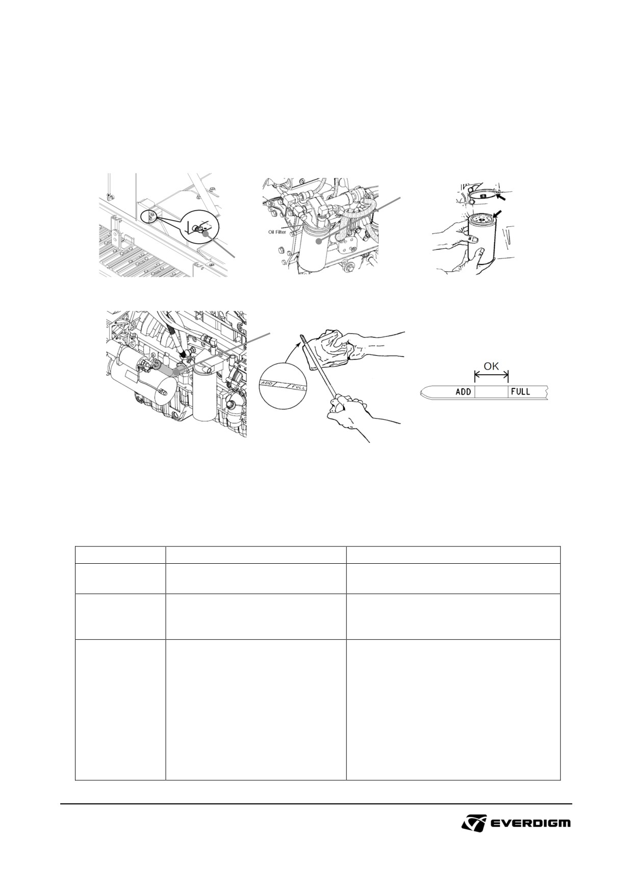
5.4.1 Engine oil, oil filter and fuel filter replacement.
Engine oil, oil filter
: Maintenance interval (50 hour after first operation, Every 250 engine hour)
2
1
Figure: Drain port
Figure : Oil filter
Figure: Filter change
3
Figure : Dip Stick
Note:
The above figures may be different according to engine models.
Table: Engine oil and filter maintenance
Check point
Parts
Instruction
Prepare empty bottle, and drain
1
Engine oil drain cock
engine oil by opening drain cock.
Remove old filter and replace with
Oil filter
new one. During filter change, check
2
the seal or gasket on the filter
Putting engine oil and pull out dip
stick.
Clean it with rug, and put the dip
stick and pull out then check oil
amount.
3
Dip stick
Refill the engine oil.
Run engine for 3 minutes with idle
rpm, then stop the engine and wait
10 ~ 20 minutes.
Check oil amount by dipstick, and
refill engine oil repeatedly.
129
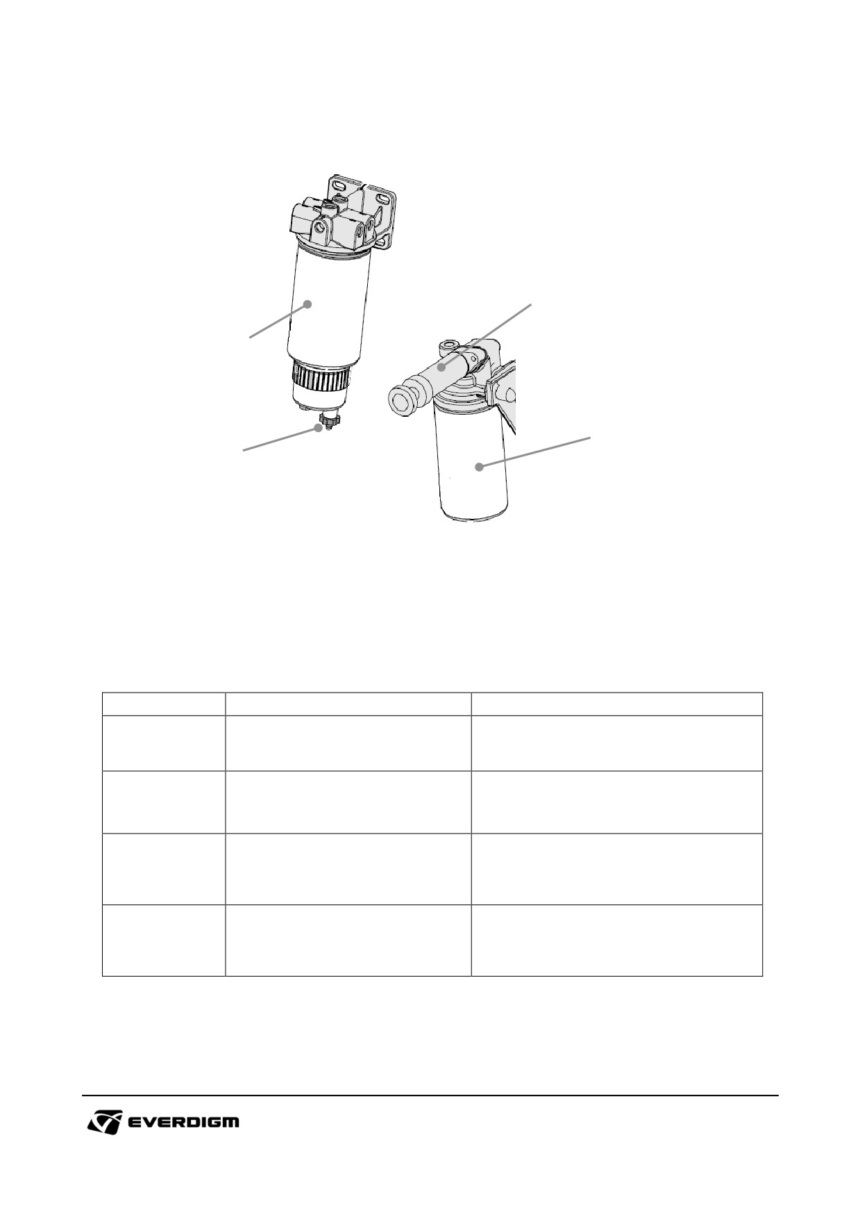
Fuel filter and water separator
: Maintenance interval (50 hour after first operation, Every 250 engine hour)
4
1
3
2
Figure : Fuel water separator and fuel filter
Note:
The above figures may be different according to engine models.
Table: Fuel-water separator and fuel filter
Check point
Parts
Instruction
Remove old filter and replace new
1
Fuel-water separator
filter
according to maintenance
schedule.
Before starting engine, drain water
2
Water drain cock
by drain cock (Everyday).
Remove old filter and replace new
3
Fuel filter
filter
according to maintenance
schedule.
After replacing fuel filter, push lifting
4
Fuel lift pump
pump several times to lift up the fuel
to engine.
130
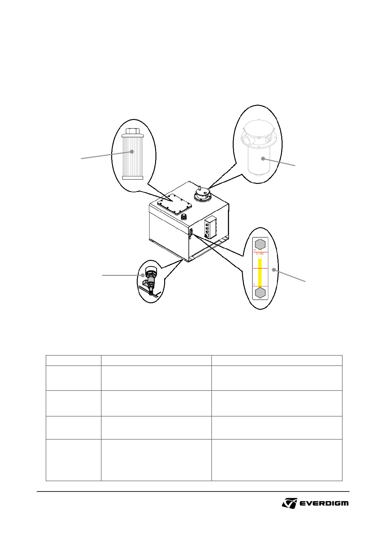
5.4.2 Hydraulic oil and return filter replacement.
Hydraulic oil and filter
: Maintenance interval (50 hour after first operation, Every 500 engine hour)
3
2
1
4
Figure : Hydraulic oil drain
Table: Hydraulic oil and return filter replacement
Check point
Parts
Instruction
Prepare empty bottle, and drain
1
Hydraulic oil drain
hydraulic oil by opening drain cock.
Dismantle hose connection and
2
Return filter
remove old filter and replace with
new one
Dismantle cover plate and remove
3
Suction filters
old suction filters and replace with
new ones.
After putting hydraulic oil, operate
equipment slightly, then turn off
4
Level gauge
engine and check oil level.
If required, refill hydraulic oil on the
tank
131
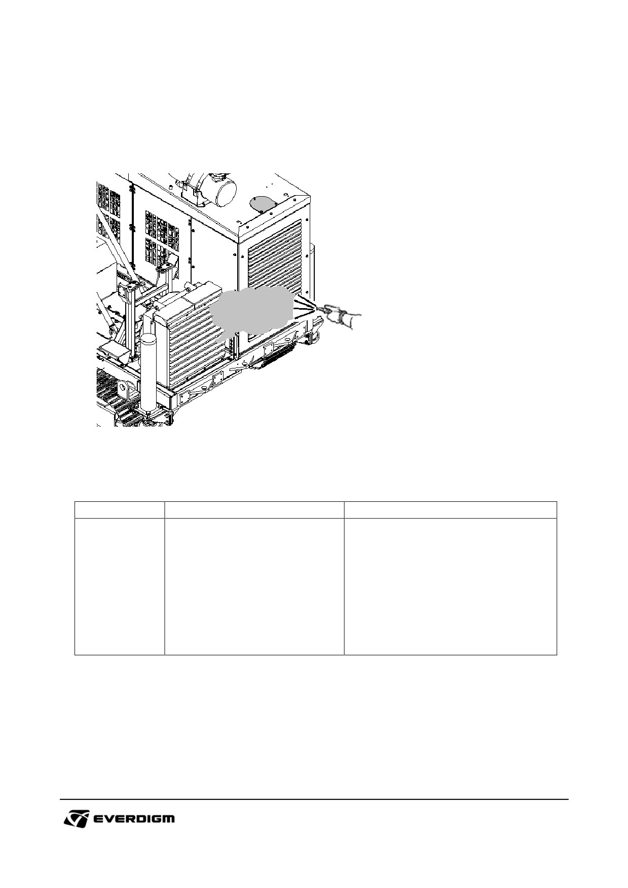
5.4.3 Cooler and radiator cleaning.
Radiator and cooler cleaning
: Maintenance interval (Daily, after operation)
Figure : Cooler and radiator cleaning
Table: Cooler and radiator cleaning
Check point
Parts
Instruction
Cleaning with air gun.
The cooling fins are very thin and
easy to be damaged by pressure.
Cooler, Radiator, Air conditioner
When using air gun, keep a distance
-
heat exchanger
unless fins will be damaged.
Do not use chemical cleaner on
cooler which can cause corrosion on
pin and cooler
132
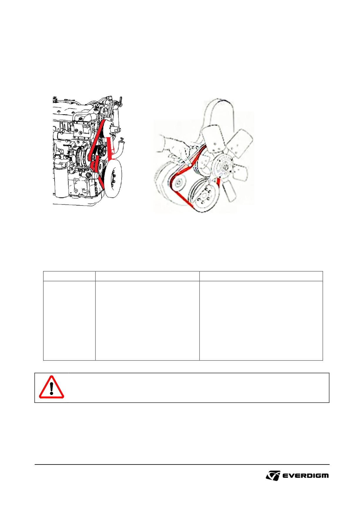
5.4.4 Engine belt tension check
Engine belt tension check
: Maintenance interval (Daily, before operation)
Figure : Engine belt and tension check
Note:
The above figures may be different according to engine models.
Table: Engine belt maintenance
Check point
Parts
Instruction
Dismantle belt cover, and push belt
with finger (about 10kg). Allowable
range of deformation is around 10 ~
15 mm.
If tension is too loose, adjust tension
-
Engine belt
according to engine maintenance
manual.
If belt is likely to break or worn out
badly, replace it with new one.
DANGER!
Do not run the engine during belt tension check.
133
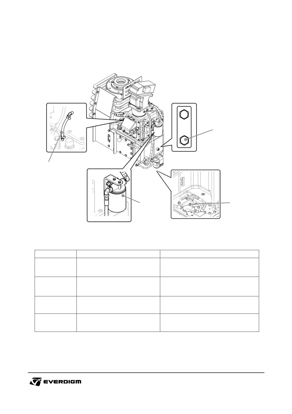
5.4.5 Rotary head maintenance
Maintenance intervals
: Maintenance interval (Daily, before operation)
2
1
3
4
Figure : Rotary head maintenance
Table: Rotary head maintenance
Check point
Parts
Instruction
Check lubrication oil circulation
1
Silicon hose
during operation.
Dismantle plug and check if oil
2
Lubrication oil level check plug
comes out from the hole.
Replace oil filter every 250 hr engine
3
Oil filter
hour operation with lubrication oil
Replace suction filter every 250 hr
4
Suction filters
engine
hour
operation
with
lubrication oil
134
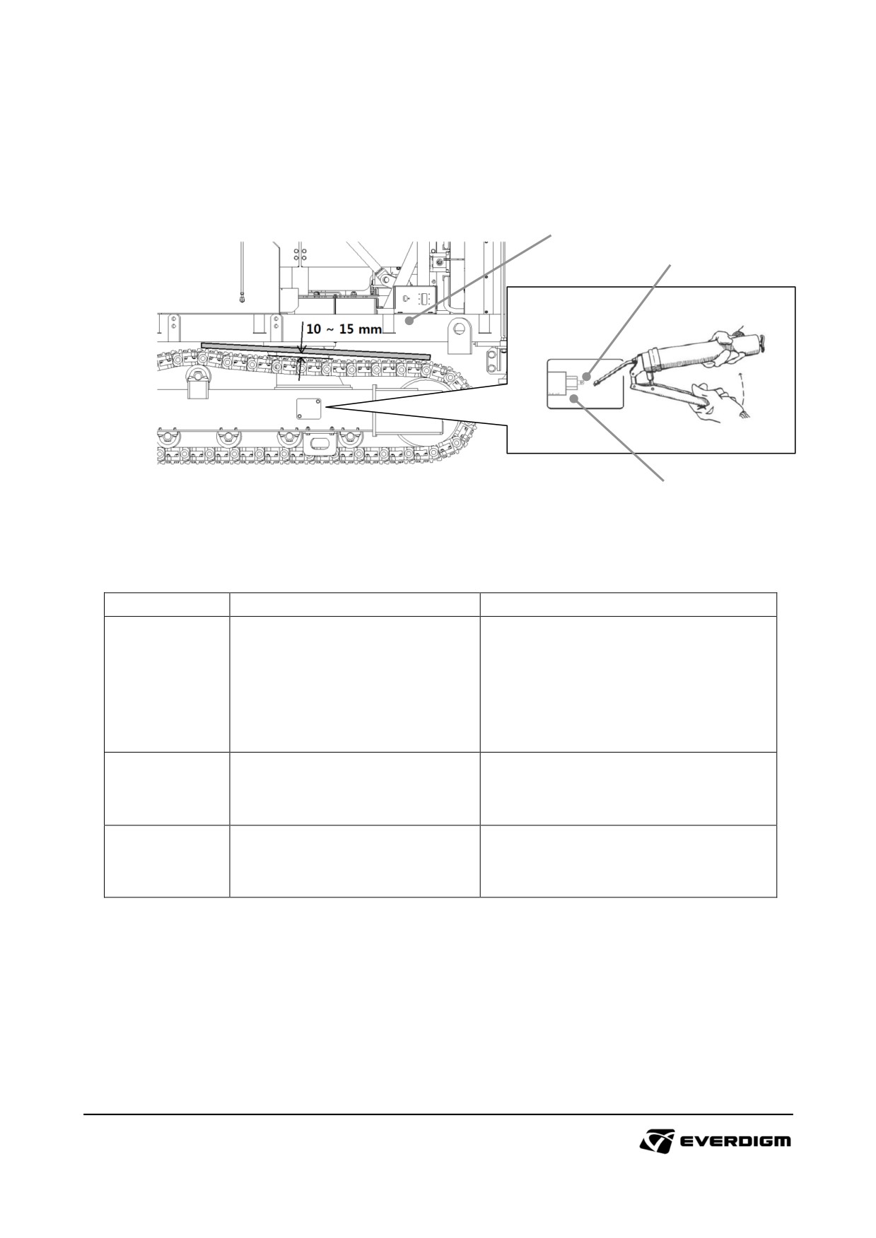
5.4.6 Track tension check
Engine belt tension check
: Maintenance interval (Weekly, before operation)
1
2
3
Figure : Track tension check
Figure : Track tension adjustment
Table: Track tension check and adjustment
Check point
Parts
Instruction
Put the machine on flat and firm
ground.
1
Track tension check
Put straight plate or bar on the track
and check the gap. Proper gap is 10
~ 15 mm.
If tension is too loose, open cover
2
Grease nipple
plate and supply grease on the
nipple.
If tension is too tight, dismantle
3
Check valve
check valve, and grease will come
out.
135
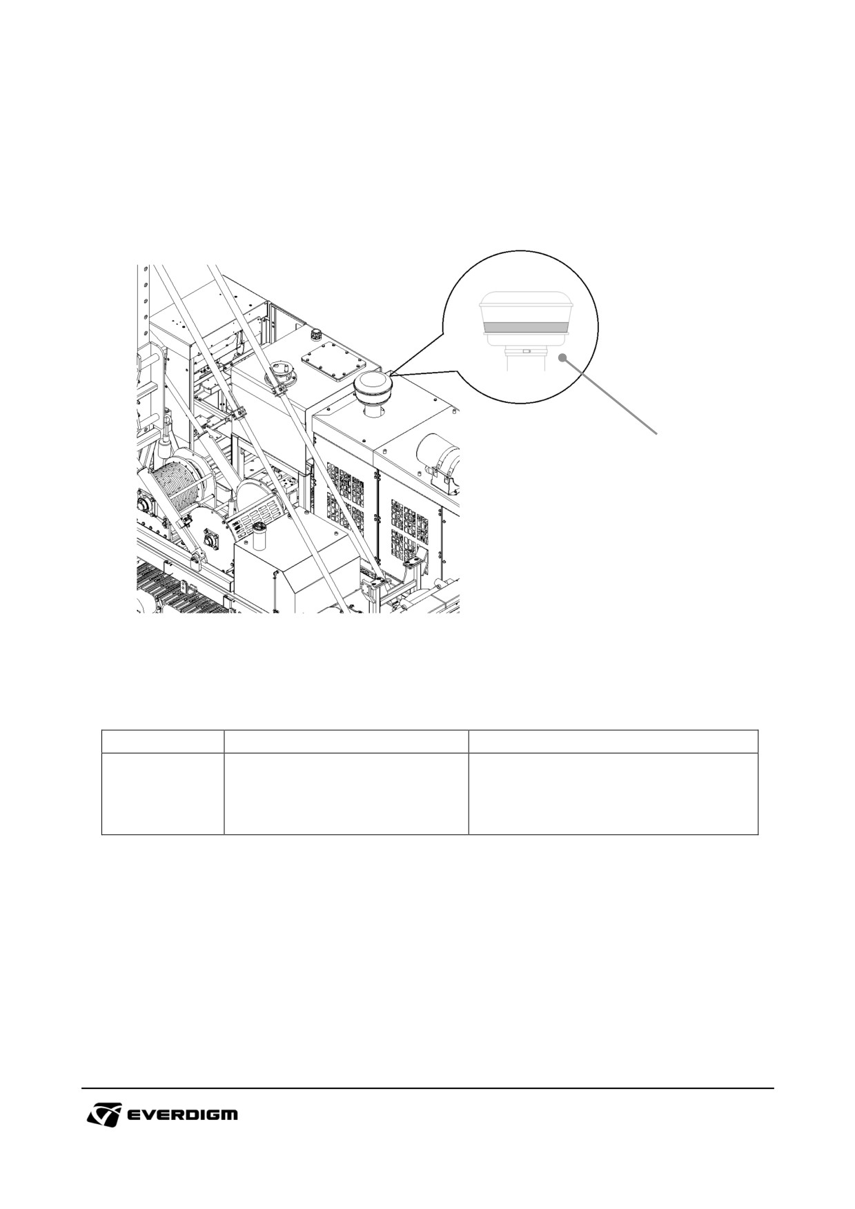
5.4.7 Air filter cleaning
Pre-cleaner
: Maintenance interval (Weekly, after operation)
1
Figure : Air pre-cleaner
Table: Air pre-cleaner maintenance
Check point
Parts
Instruction
Remove pre-cleaner and remove
1
Air pre-cleaner
dusts.
136
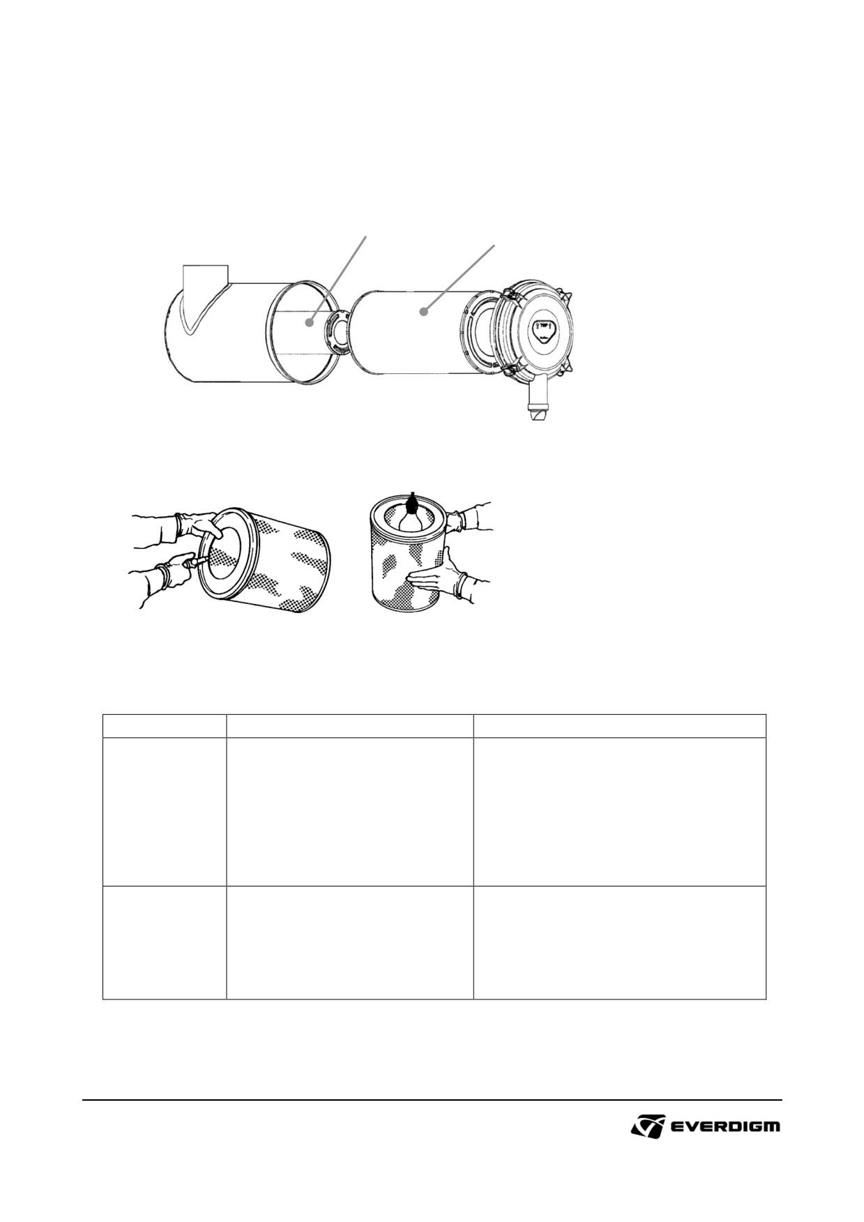
Air cleaner filter maintenance
: Maintenance interval (Weekly, after operation)
2
1
Figure : Air filters
Figure : Air filter cleaning and inspection
Table: Air cleaner filters maintenance
Check point
Parts
Instruction
Open air cleaner cap.
Dismantle primary air filter, and
1
Primary air filter
clean it with air gun.
Inspect, and replace new filter if old
one is damaged.
Dismantle secondary air filter, and
clean it with air gun.
2
Secondary air filter
Inspect, and replace new filter if old
one is damaged.
137
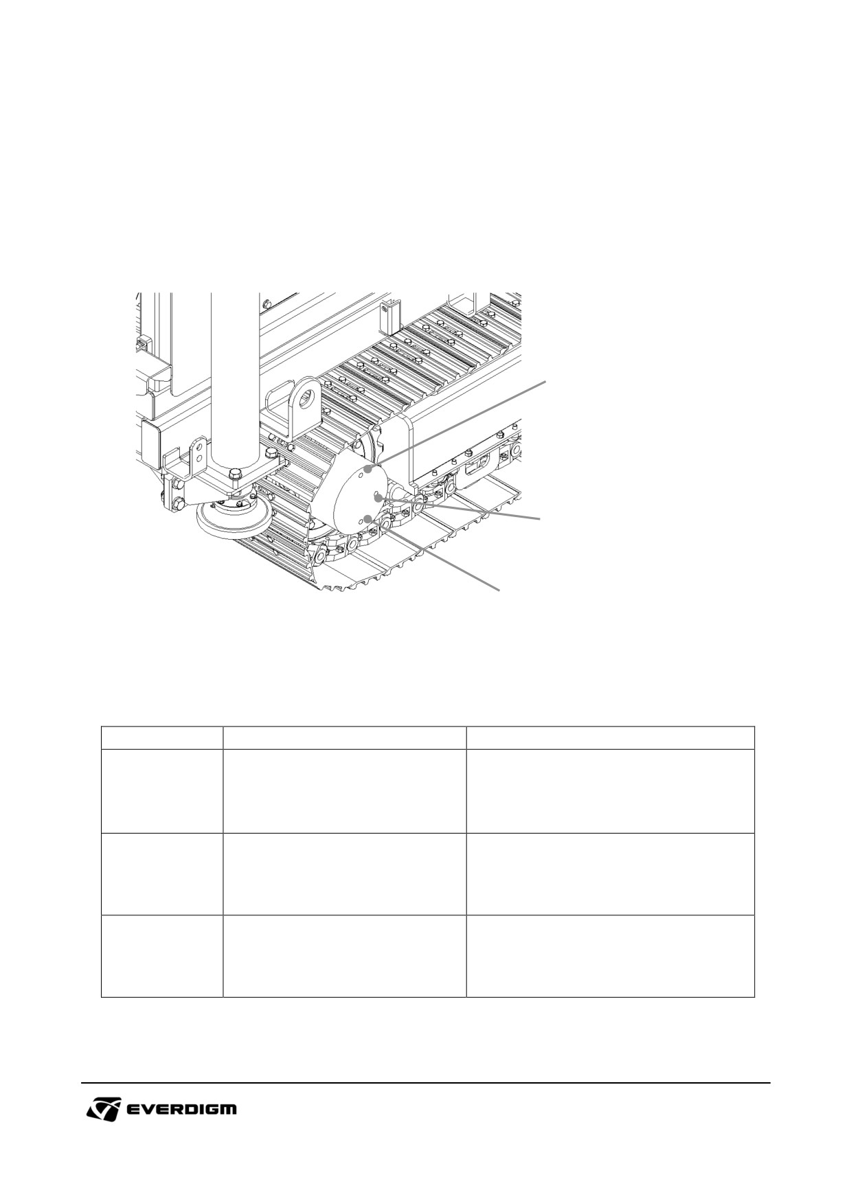
5.4.8 Travel motor oil replacement
Travel motor oil replacement
: Maintenance interval (500 hour after first operation, Every 1000 engine hour)
3
2
1
Figure : Travel motor oil replacement
Table: Feed motor oil replacement procedure
Check point
Parts
Instruction
Dismantle plug for draining oil.
1
Oil drain plug
After draining oil completely, tighten
it.
Before putting oil, open the plug.
2
Oil level check plug
When oil come out from the hole,
stop oil filling and assemble plug.
Loose plug for filling oil. After filling
3
Oil filling plug
oil tighten it.
138
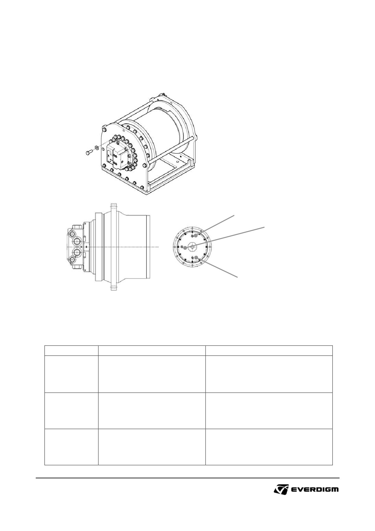
5.4.9 Main winch motor oil replacement
Main winch motor oil replacement
: Maintenance interval (500 hour after first operation, Every 1000 engine hour)
3
2
1
Figure : Main winch motor oil replacement
Table: Main winch motor oil replacement procedure
Check point
Parts
Instruction
Dismantle plug for draining oil.
1
Oil drain plug
After draining oil completely, tighten
it.
Before putting oil, open the plug.
2
Oil level check plug
When oil come out from the hole,
stop oil filling and assemble plug.
Loose plug for filling oil. After filling
3
Oil filling plug
oil tighten it.
139
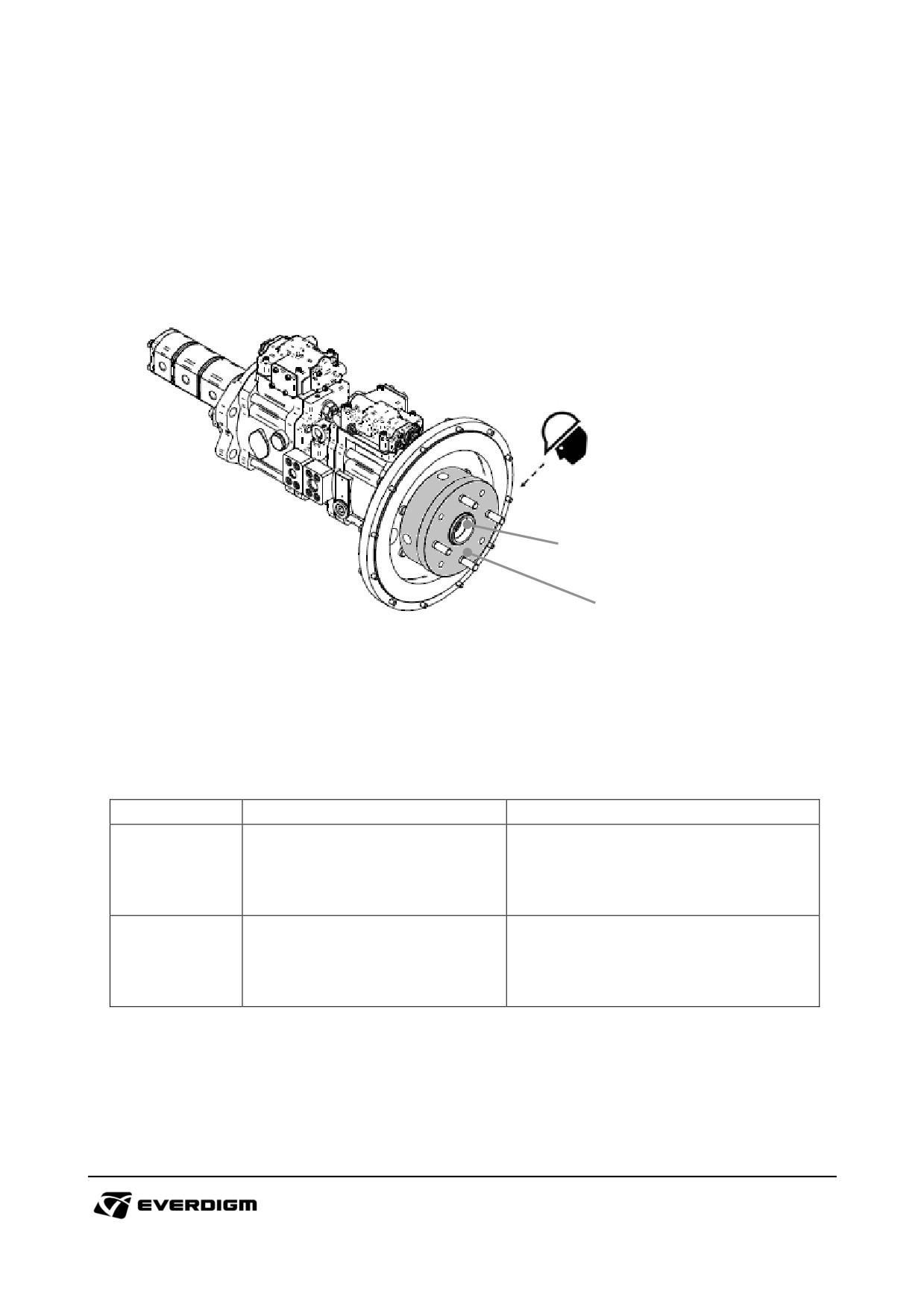
5.4.10 Flexible coupling maintenance
Flexible coupling maintenance
: Inspection (Every 50th engine hour)
: Replacement (Every 2000 engine hour)
2
1
Figure : Flexible coupling (Centerflex) and hubs
Note:
The above figures may be different according to engine models.
Table: Oil separator replacement
Check point
Parts
Instruction
Check wear condition by inspection
(every 50 engine hour)
1
Flexible coupling
Replace flexible couplings
(every 2000 engine hour)
Check damage and wear
(every 50 engine hour)
2
Hub
Replace hubs
(every 2000 engine hour)
140
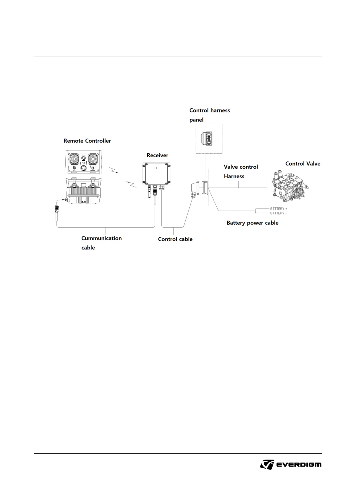
6. Options
6.1 Remote controller
For safe travel operation, remote control can be equipped and supplied as option.
6.1.1 Components
Figure: Remote controller.
Remote control send signal to operate travel motors. It provides safe operation for machine traveling.
Wireless control and cable control can be available.
When wireless control is out of order, connect communication cable and operate it with cable line until
it being repaired.
If cable / wireless operation has malfunction, operate it with manual lever and contact Everdigm official
service for repair.
141
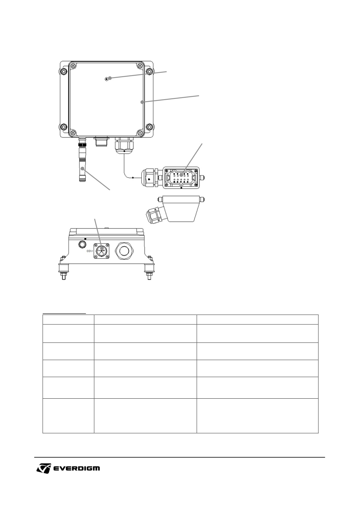
6.1.2 Receiver
1
5
2
3
4
Figure: Receiver.
Table: Receiver.
Item
Name
Description
1
Working LED lamp (Green)
It shows the condition of receiver.
It connects control valve and battery
2
Control harness connector
for operation.
It receives the wireless signals from
3
Antenna
remote controller
It
is the input line for cable
4
Control cable connector
connection with remote controller.
When receiver connects with remote
Cable / Wireless control mode
5
controller by cable, press the switch
selection switch
to activate the cable connection.
142
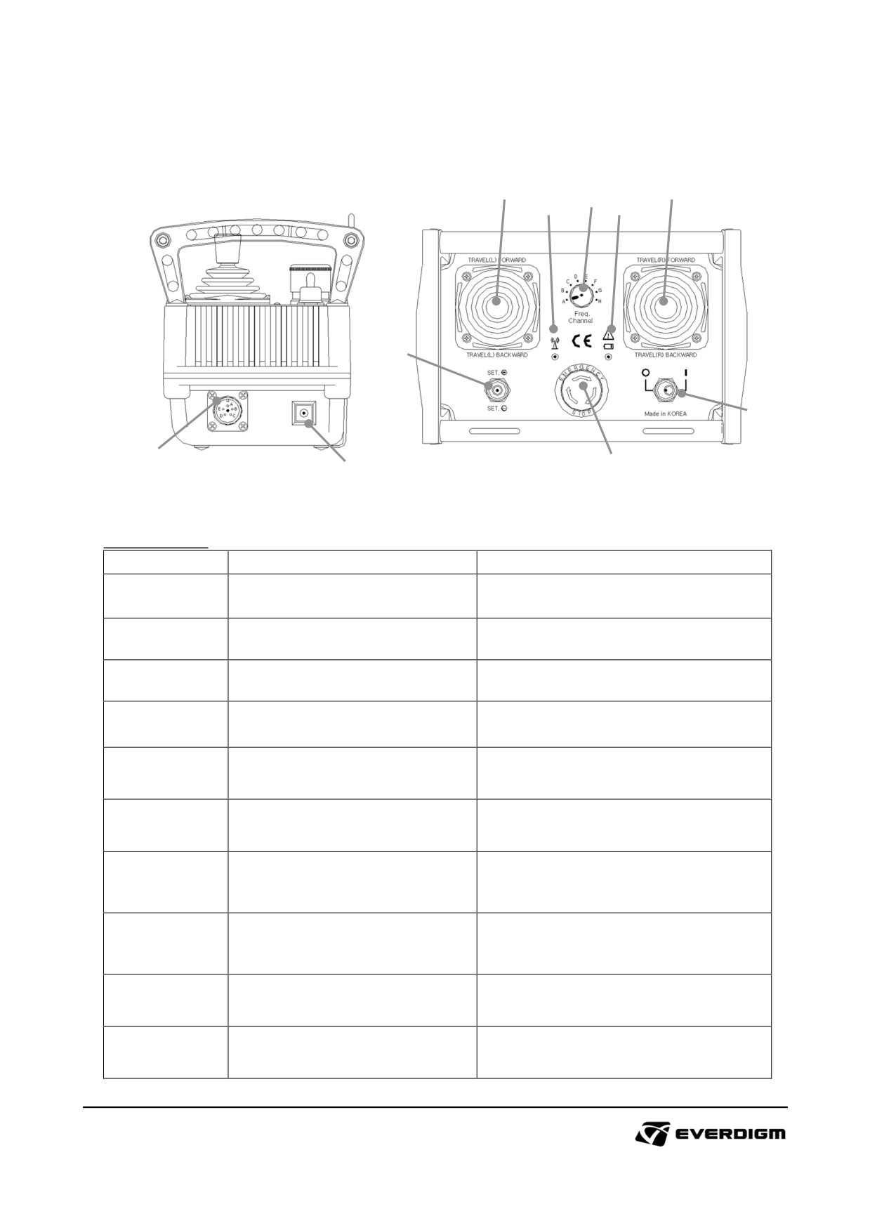
6.1.3 Remote controller
1
2
3
4
5
6
8
9
7
10
Figure: Remote controller.
Table: Receiver.
Item
Name
Description
Left track forward
/
Backward
1
Joystick (Left travel control)
operation.
Right track forward
/ Backward
2
Joystick (Right travel control)
operation.
Changing
wireless
frequency
3
Frequency channel switch
channel. See 6.1.3.1
It shows the condition of wireless
4
Working LED lamp (Green)
connection with receiver.
It blinks every seconds when low
5
Battery warning lamp (Red)
battery is detected.
When it has program mode, set the
6
Set switch
values with this switch. See 6.1.3.2
To stop operation immediately, press
7
Emergency stop switch
emergency switch. To release
emergency mode, rotate switch.
When power is ON and it connects
8
Power ON/OFF switch
with receiver correctly, the working
LED (4) blinks every 4 seconds
It is the output line for cable
9
Control cable connector
connection with receiver.
It can set the traveling speed. See
10
Program mode switch
6.1.3.2 for more details.
143
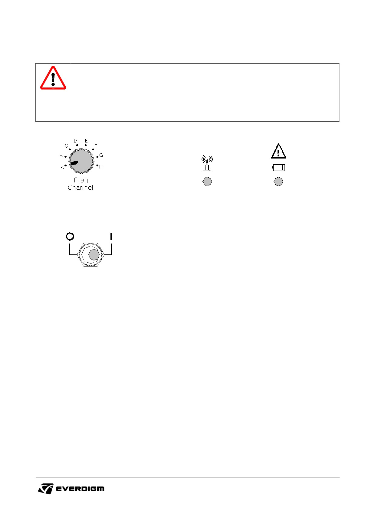
6.1.3.1 Wireless frequency channel setting
CAUTION!
All the remote controls have their own identification number to prevent interruption during the
radio control.
If both identification number of the remote controller and receiver do not correspond to each
other, remote control will not work.
Figure: Frequency channel switch
Fig: Working LED lamp & Battery warning lamp
Figure: Power ON (I) / OFF (O) switch
The wireless remote controller and the receiver have total eight radio frequency channels.
When there is wireless signal interruption by using same frequency channel or other external factors, it
should be changed to other channel by setting the frequency channel switch.
When you change the channel, make sure the power switch is on. After setting the channel, turn off
the power switch and turn on the power switch again. If the working LED lamp and the battery warning
lamp blink simultaneously, it indicates that frequency channel is changed.
144
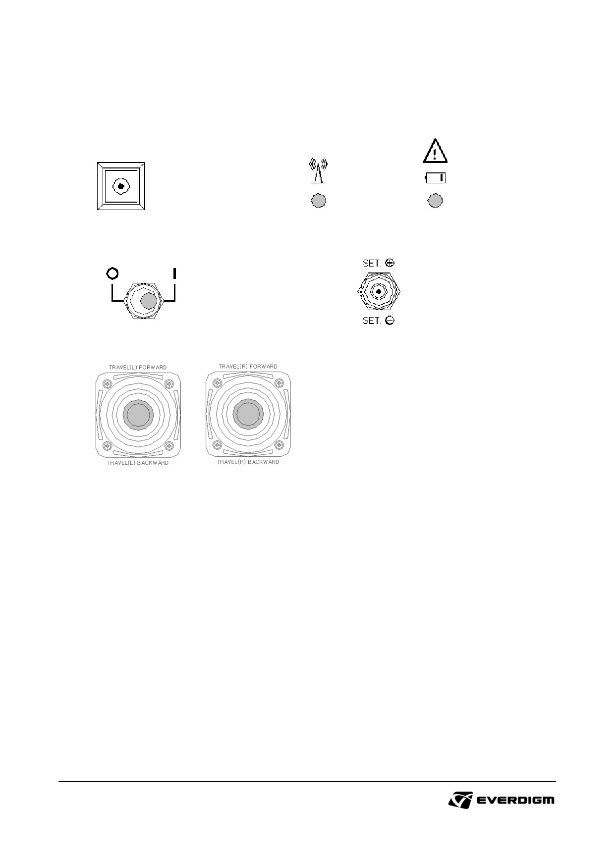
6.1.3.2 Program mode setting
Figure: Program mode switch
Fig: Working LED lamp & Battery warning lamp
Figure: Power ON (I) / OFF (O) switch
Fig: Set switch
Figure: Travel control joystick
(1) In order to switch to the program mode, turn off power switch and turn on power switch again with
the program mode switch being pressed.
(2) When working LED lamp starts to blink quickly, it indicates that it is changed over to the program
mode.
(3) To set the speed of crawler travel, tilt travel control joystick at about 15 degree angle and set the
MIN value with using the set switch, and then tilt travel control joystick at the maximum angle and
set the MAX value using the set switch.
(4) To change over to the action mode, turn off the power switch and turn on the power switch again
when all the setup is finished.
145
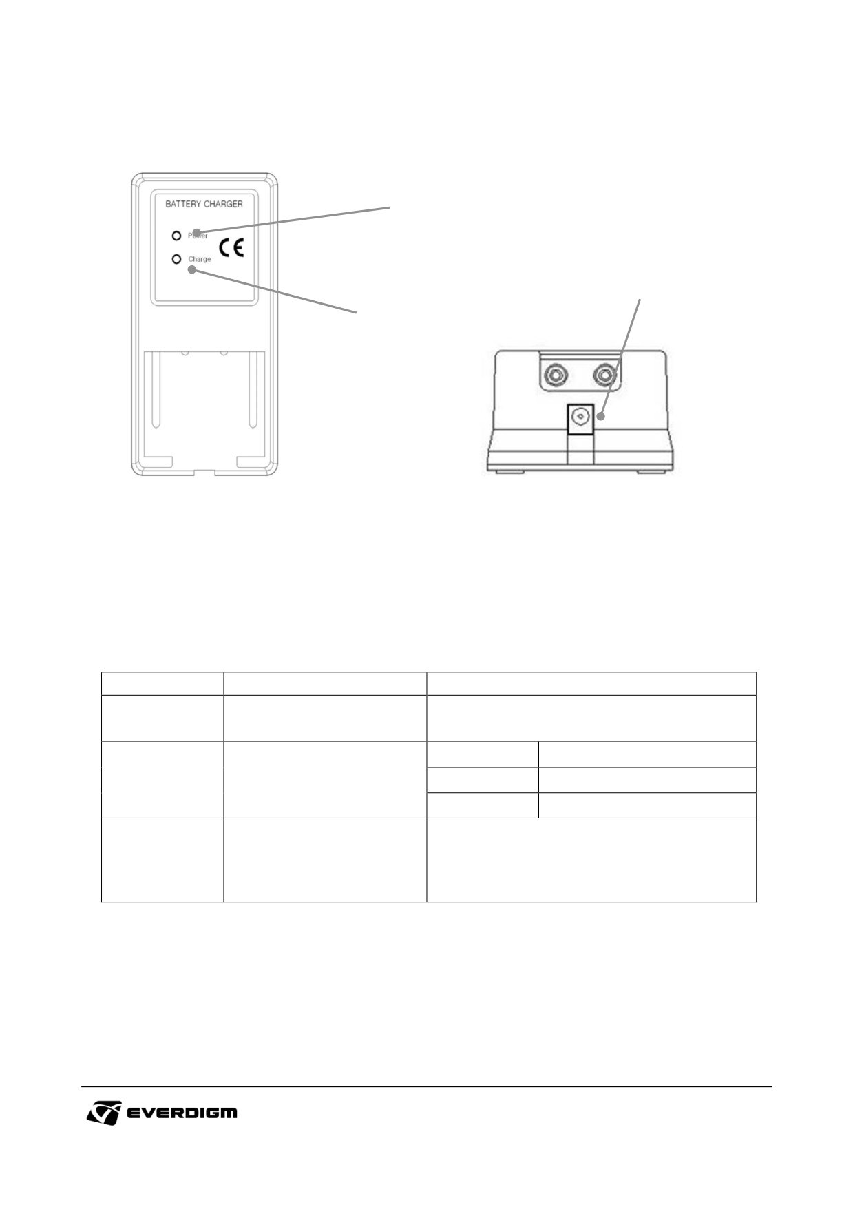
6.1.3.3 Battery and battery charger of remote controller
1
3
2
Figure: Battery
Fig: Battery charger
Use genuine battery only. Do not dismantle battery charger.
Charge battery after it is completely empty. Once battery is fully recharged, it can be used about
14~16 hours.
The number of repeat of charging and discharging battery is 600 times. It is not recommended
recharging the battery too frequently.
Table: Battery and battery charger
Check point
Parts
Instruction
It shows the condition of battery
1
Power LED lamp
Red light : Activated.
Red
Need recharge
2
Charge LED lamp
Orange
Charging is progressing
Green
Charging completed
3
Electric connector
DC connector (12V ~ 24 V)
146
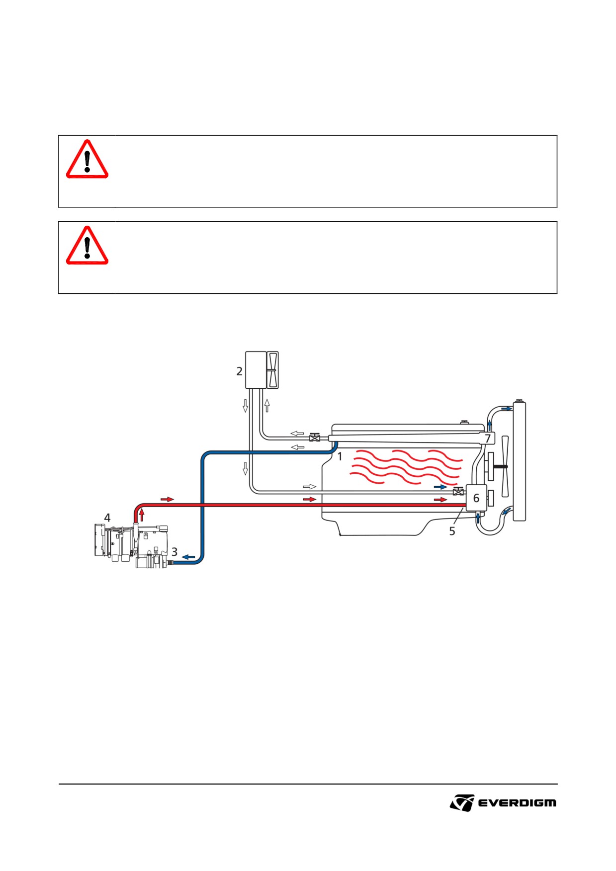
6.2 Engine coolant preheating system
Engine coolant preheating system is adapted as option to supply heat on engine at a designated time.
Webasto coolant heating system provides easy engine start in cold climate area.
DANGER!
Do not touch coolant preheating system including pipes while it is running. The heater will
generate heat, and you may hurt by heat.
IMPORTANT!
The electricity is constantly consumed by heater. When machine is likely stored more than 1
week, turn off master switch and disconnect battery from machine.
6.2.1 System configuration
Figure : Coolant preheating system
1
:
Coolant supply connection
2
:
Radiator
3
:
Coolant pump
4
:
Coolant heater
5
:
Coolant return connection
6
:
Engine coolant pump
7
:
Thermostat
147
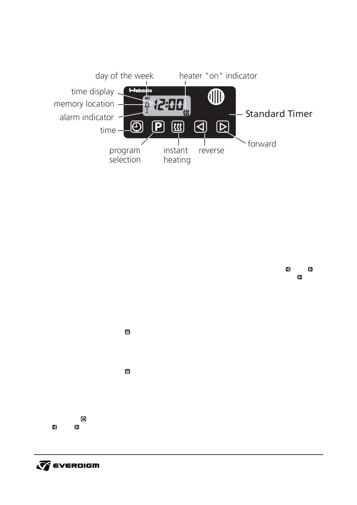
6.2.2 Timer setting
General
The standard digital timer enables you to preset the start of the heater operation up to 7 days in
advance. It is possible to program 3 different starting times, only one of which can be activated.
The standard digital timer features a wakeup alarm function.
When the ignition is switched on, the timer displays the current time and the day of the week. When
the heater is switched on, the display and buttons are illuminated.
After the power supply has been connected, all symbols on the display will flash. The current time and
weekday must be set.
Operation
The timer can be operated in that all flashing symbols can be adjusted by means of the
and
buttons. If the buttons are not pressed within 5 seconds, the time displayed will be stored. If
button
is pressed for more than 2 seconds, the fast time setting mode is activated.
If the ignition is switched off while the heater is operating in the continuous mode, the remaining
operating time of 15 minutes is displayed and the heater continues to operate for this period of time.
Switching the heater on
Manually : by pressing the
button (continuous heating mode).
Automatically : by programming the heater starting time.
Switching the heater off
Manually : by pressing the
button (continuous heating mode).
Automatically : after the programmed operating time has elapsed.
With the heater running : by programming the remaining operating time.
Setting time / day of the week
Press the
button for more than 2 seconds - time of the day is flashing - and set the clock using the
and
buttons. Day of the week is flashing - adjust the day of the week.
148
Viewing the time
With the ignition switched off : press the
button.
Programming heater starting time
Press the
button - the memory location is flashing - using
and
buttons set start of the
heater operating time. Day of the week is flashing - set the day of the week. By repeatedly pressing
the
button, memory locations 2 and 3 can be programmed or the timer display mode can be
reached.
Recalling / erasing preset times
Repeatedly press the
button until the desired memory location is displayed. To erase the preset
time, press the
button several times until the time of the day is displayed instead of the memory.
Programming duration of operating time
The heater must be switched off. Press the
button for 3 seconds - operating time is flashing - and
set the desired operating time (10 to 120 minutes) using the
and
buttons.
Setting the remaining operating time
Set the desired remaining operating time (1 to 120 minutes) using the
and
buttons. The
remaining operating time refers to the time the heater still continues to remains in operation. It can
only be changed while the heater is in operation and the ignition switched off.
Setting the wake up time
A wake up time can only be programmed on the standard digital timer. The wakeup time is not bound
to a specific day of the week.
Repeatedly press the
button until the bell symbol
appears on the display. Set the desired
wakeup time using the
and
buttons. The alarm clock turns off after 5 minutes or when one of
the buttons is pressed.
Recalling / erasing the wakeup time
Repeatedly press the
button until the bell symbol
appears on the display - read off wakeup
time. To erase the wakeup time : press the
button until the bell symbol
is no longer visible on
the display.
Remote control
Possible by means of an optional external "instant heating" button.
149