EVERDIGM Core Drill Rig ECR12 & ECR18. Operation and Maintenance Manual (2016.02.27) - page 2
STANDARD EQUIPMENT
Manual controlled crawler
4 hydraulic leveling jacks
Rod kicker
Drill speed gage
Mud pump pressure gauge
Front, rear headlight and work light
Hydraulic connection for mud pump and mud mixer
Mechanically fail safe hydraulic foot clamp
Side shift rotary head
Rotation guard
Rod make-up / break-out
Wire line hoist
Centralized grease lines for crown pulley
Chuck and foot clamp are equipped with HQ-sized jaws as a standard. Upon request, chuck can be equipped with
BQ/NQ/PQ-sized jaws, foot clamp can be equipped with BQ/NQ/PQ/PW-sized jaws.
OPTIONS
Hydraulic driven mud pump
Manufacture:
American manufacturing
Model:
AW1122BCD
Max flow:
130 Lpm (34.3 gpm)
Max pressure:
5 MPa (725.2 psi)
Hydraulic driven mud mixer
Max flow:
56.7 Lpm (15 gpm)
Max pressure:
10.4 MPa (1500 psi)
Remote controlled crawler (cable and wireless control available simultaneously)
Wireline hoist with level winder
Extendable outrigger
Upper hoist limit
Spin cage with safety device
Side safety guard
Dimension kit
BQ chuck jaw/bushing kit & foot clamp jaw kit
NQ chuck jaw/bushing kit & foot clamp jaw kit
HQ chuck jaw/bushing kit & foot clamp jaw kit
PQ chuck jaw/bushing kit & foot clamp jaw kit
PW foot clamp jaw kit
50
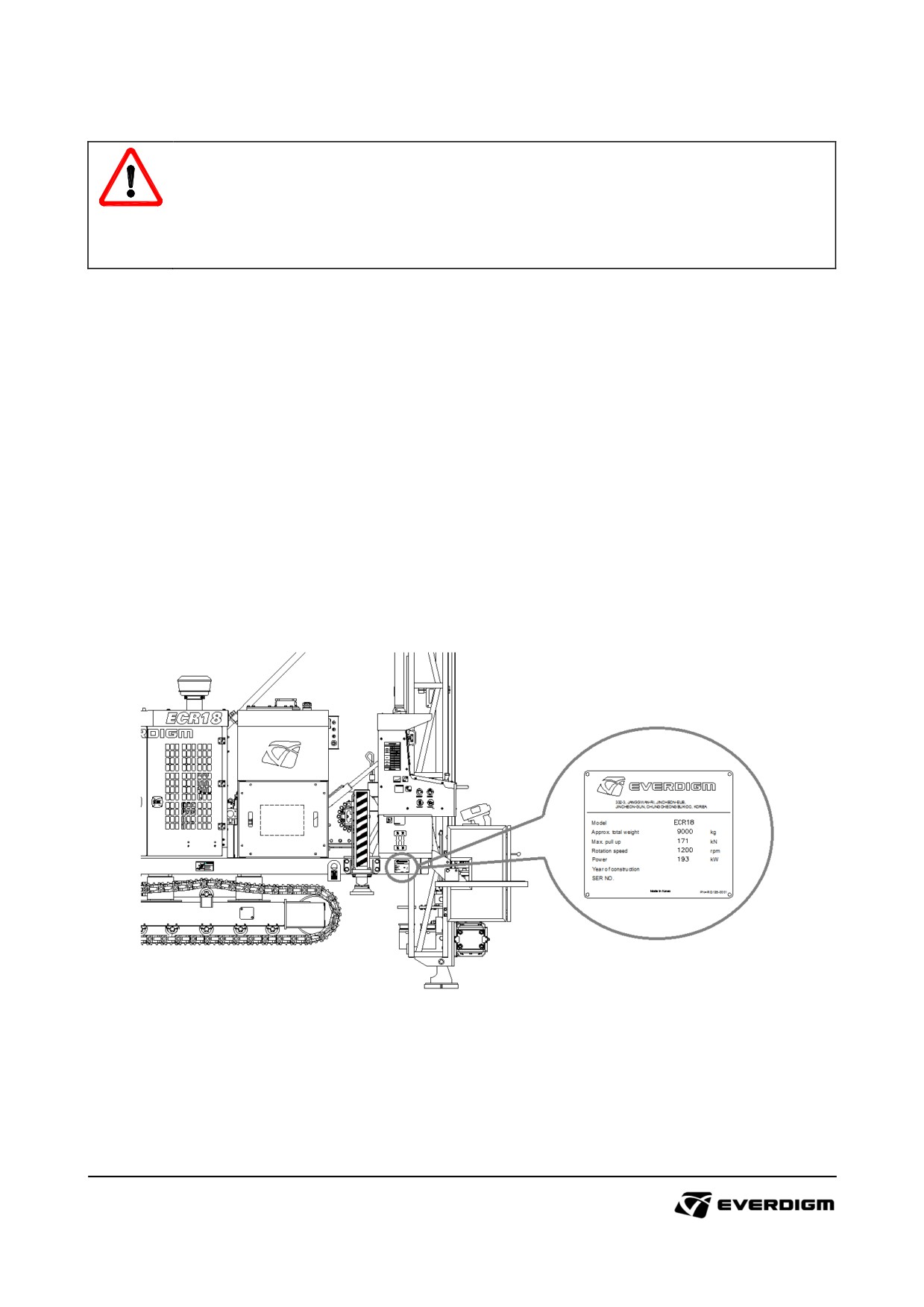
2.5. Information for ordering parts and service
IMPORTANT!
Parts may subject to changed for improvement. It is highly recommended ordering parts with
equipment serial number.
Using non-genuine or improper parts may cause shorten equipment parts life, or serious
damages on related parts.
The machine serial number is marked with the type and serial number on the nameplate. It is important to
make correct reference to the serial number of the equipment when making repairs or ordering spare parts.
Identification by serial number is the only proper means of maintaining and identifying parts for specific
machine.
Model Code and Serial Number
( {: Number, : Alphabet )
Model code: ECROO
Serial Number : {{{
Example : ECR18
Example : H001
ECR : Product prefix
(Drill Rig Model Code)
H : Factory code
18 : Pull back capacity
001 : Serial number
51
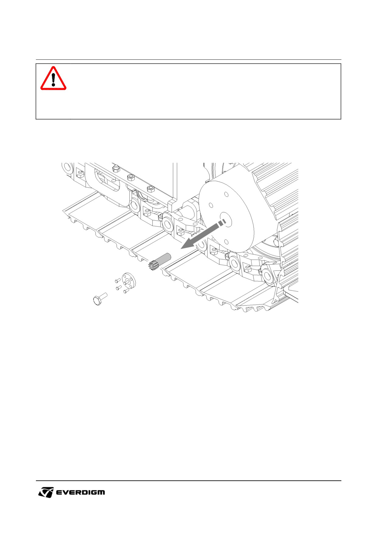
3. Towing, lifting and transporting method
DANGER!
Follow local road safety regulations on weight, width and height limits. (Transporting)
Check strength of wire and hook condition and weight capacity before towing and lifting
equipment.
Do not stay inside of cabin or operate equipment while it is towed, lifted and moved by trailer.
3.1 Towing
① Before releasing brake, the equipment should be stand on flat ground, or supported firmly with high
strength wires on uneven ground.
② Dismantle plug from travel motor.
③ Dismantle cover plate from travel motor.
④ Remove drive gear from inside of travel motor.
④ Assemble and tighten cover plate and plug.
52
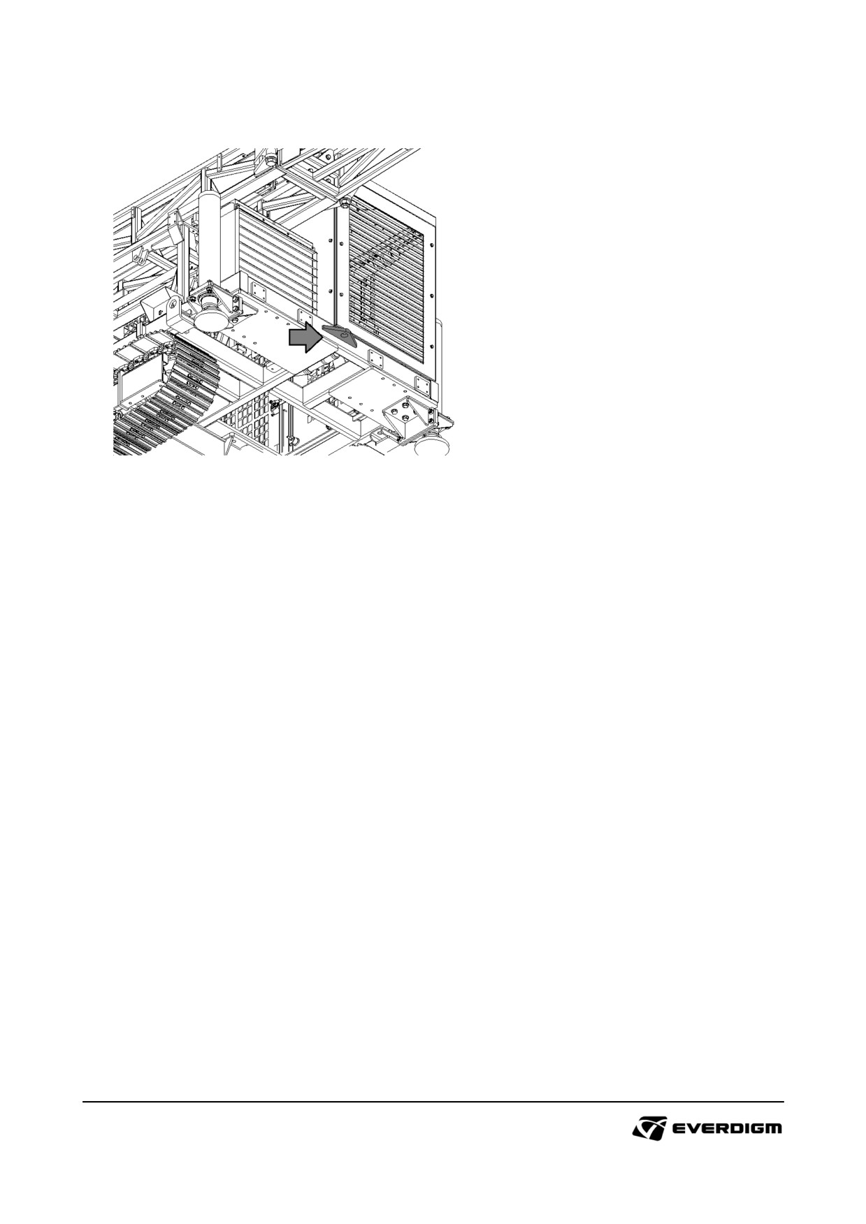
▶ Hook points
< Rear Side >
▶ Note
: Hook point location or shape may different according to core drill model.
: After towing, replace gear oil as describes "5.4.10 Travel motor oil replacement".
53
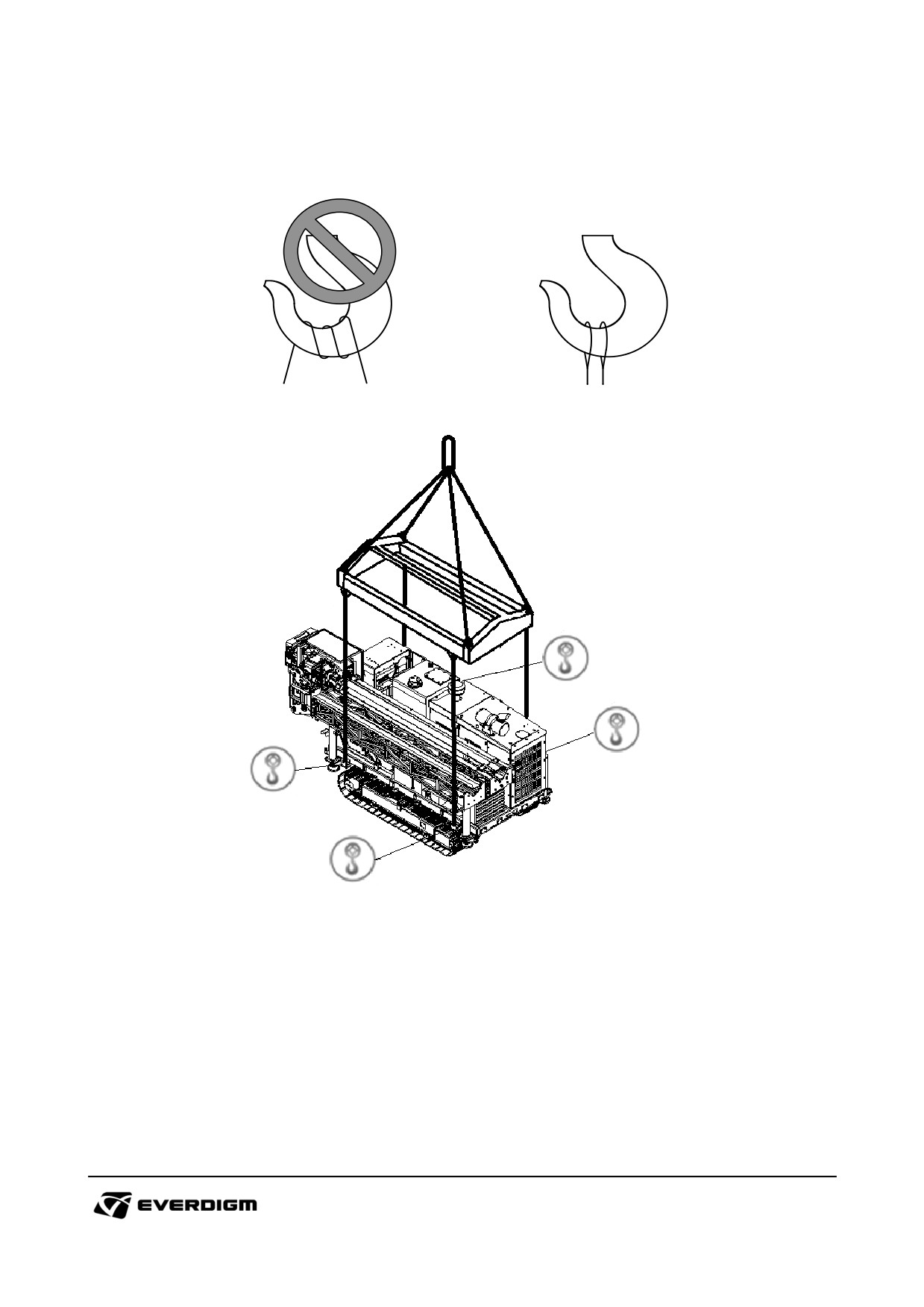
3.2. Lifting
Incorrect
Correct
• Wires and blocks which support the machine should be strong to lift it.
• Mast should be folded and firmly settled on the supporter. No movement of mast is allowed.
• Wires should not touch mast or bonnet during lifting procedure.
• Do not wind wire on hook. Wire should be securely hold.
54
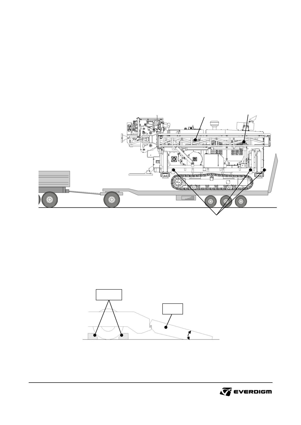
3.3. Transportation
Guideline for transportation
① Fold mast, and set the mast to horizontal position.
② Mast should be firmly settled on the supporter above the frame. If possible, tied up the mast with
supporter and trailer.
③ Tied up equipment with trailer bed correctly.
1
2
3
Loading and unloading on trailer
① Width of trailer should be wider than equipment track.
② Pay special attention for driving when the equipment is loaded on the trailer.
③ Fix ramps on the trailer tightly, and angle of slope need to be less than 15 degree from ground.
Stopper
Ramp
Max 14˚
55
4. Operation
DANGER!
Follow recommended guideline on this chapter. Improper operating method will cause injury
or death of person, and damages to equipment.
Only trained and skilled operator can operate the equipment. Do not leave from the operator
panel while it is in operation.
Do not stand nearby machine.
Never attempt operate the machine when danger situation is predicted.
Failure or damage on machine is noticed, stop the machine immediately. Then, put warning
stickers or label to alert others until being repaired.
4.1. Before operation
Operator
√ Operator should be in good condition before operation.
√ Wear safety helmet, goggle, shoes and others for safety.
Drilling machine
√ Check wear status of sliding and rotating parts
√ Check oil leakage on hydraulic parts, fittings and hoses.
√ Check lubricating oil flow condition on rotation unit, and apply grease.
√ Check greasing condition on moving parts, and apply grease.
√ Check external condition of main parts whether it is deformed, bent or cracked.
√ Check fasteners (bolts and nuts) and pins whether it is loosen.
√ Check remained amount of engine oil, compressor oil, hydraulic oil, rotary head lubricant and fuel on
tanks.
√ Check tensions on chain, track, hoses on mast and fan belt on engine.
√ Drain water on fuel separator and fuel tank.
☞ See the details in Chapter "5. Maintenance"
56
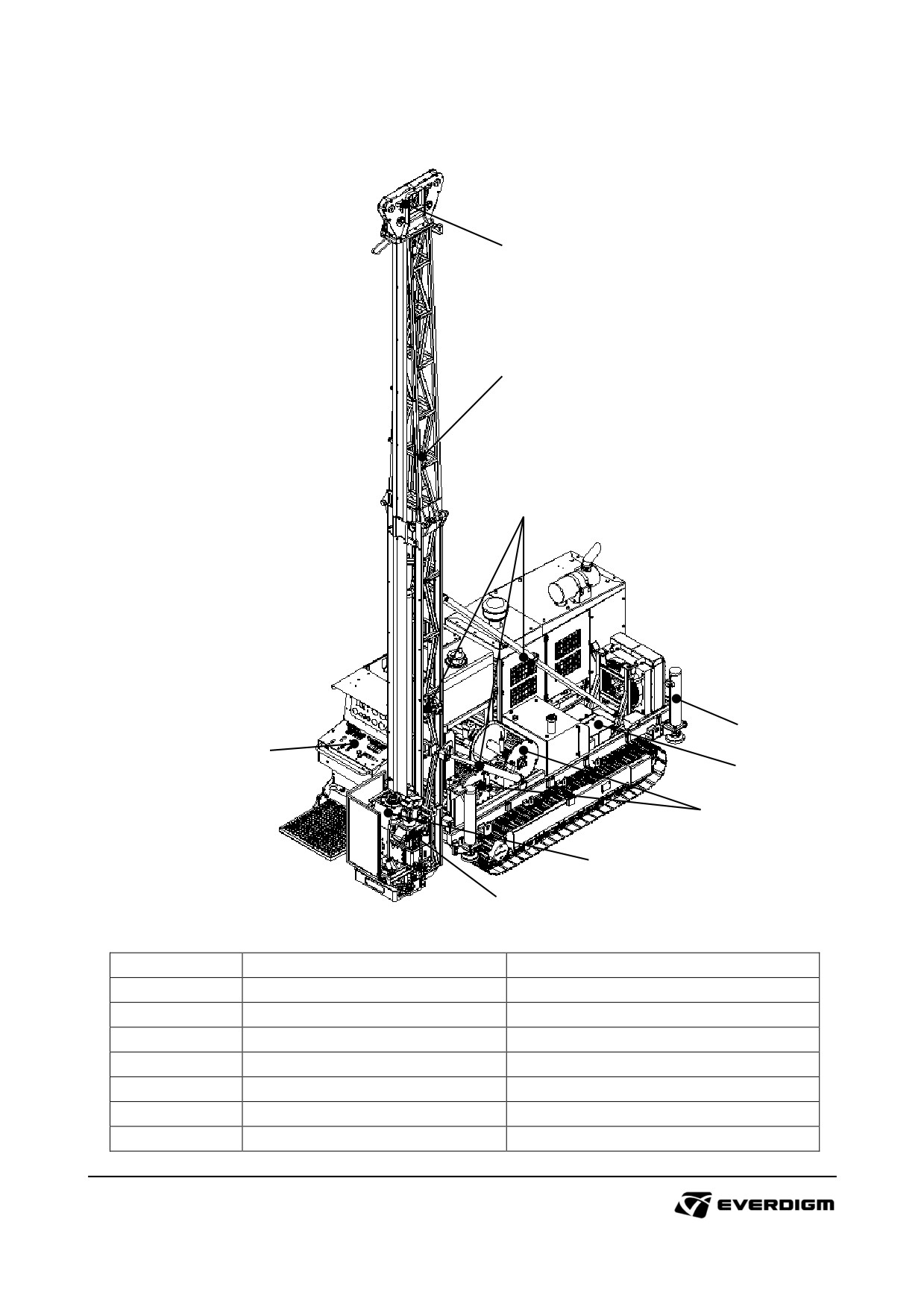
4.1.1 Check points before operation
2
1
4
9
3
8
7
5
6
Figure: Check points.
Check point
Parts
Instruction
1
Mast
Wear, deformation, crack or damage
2
Wire line pulley
Wire condition, deformation and wear
3
Control levers and switches
Functionality
4
Cylinders
Oil leakage
5
Chuck
Wear or damage on jaw bites
6
Transmission lever
Damage and functionally check
7
Wire winches
Functionally check, Damage check
57
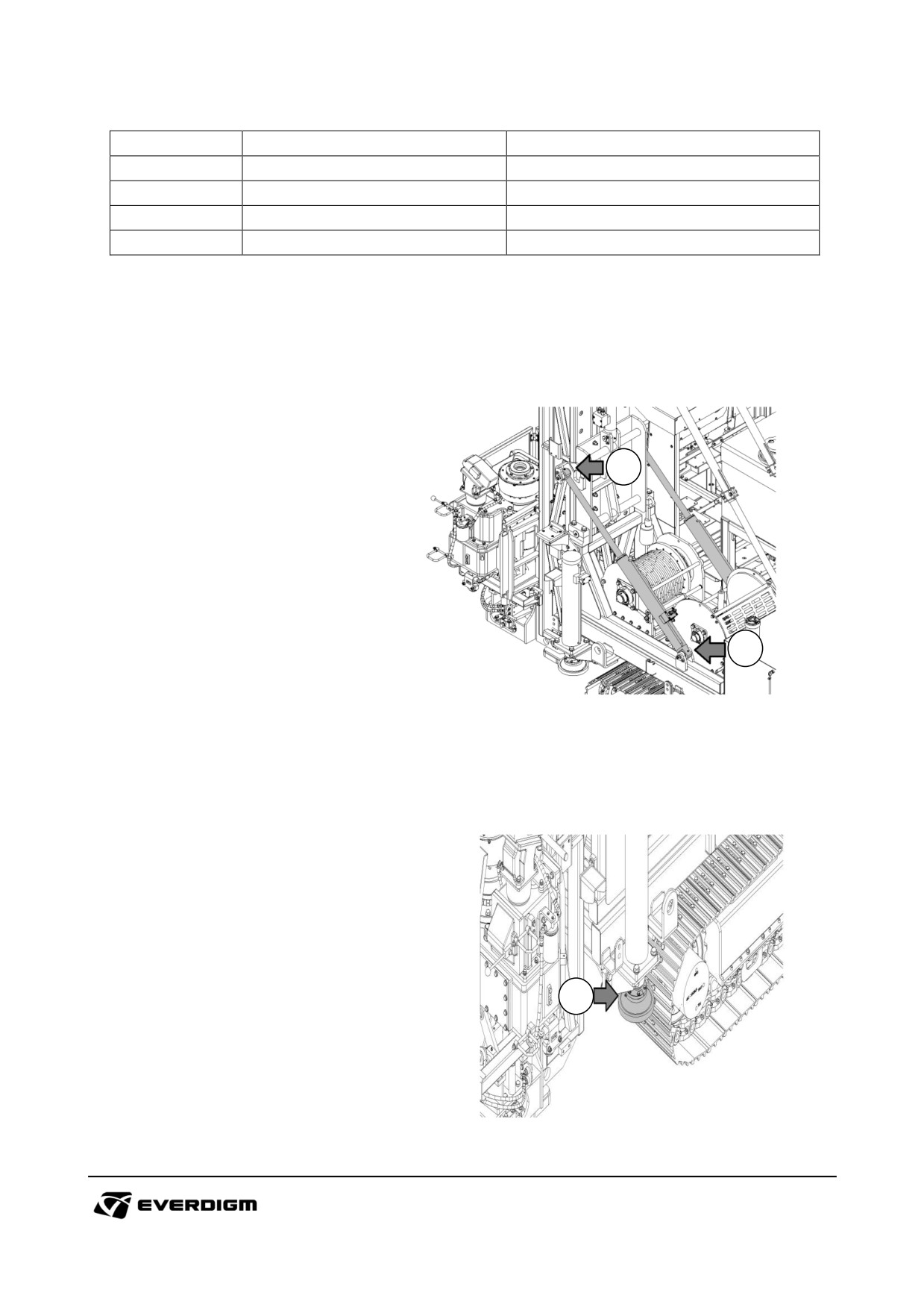
Check point
Parts
Instruction
8
Battery
Electric line connection status
9
Outrigger
Oil leakage (Internal & External)
-
Hose and pipe
Oil, fuel or gas leakage
-
Wires
Wear, loose, bending and breakage check
4.1.2 Lubrication points
Mast raise cylinders
① Lower mast raise cylinder pin
(2 places)
② Upper mast raise cylinder pin
(2 places)
2
1
Outrigger pad
① Outrigger pad (4 places)
1
58
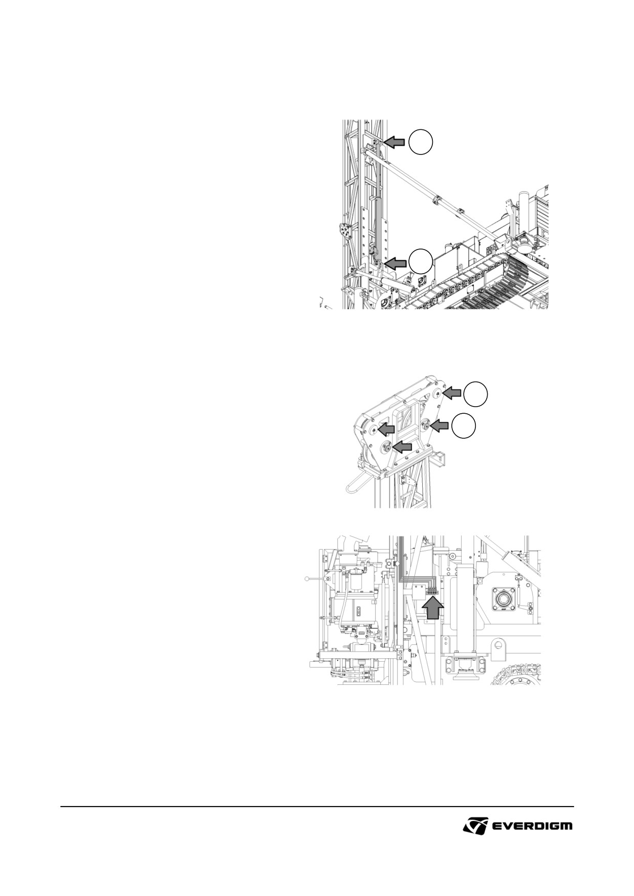
Mast dump cylinder
① Upper cylinder (1 place)
② Lower cylinder (1 place)
1
2
Wire pulley (from mast grease injection points)
① Main winch wire pulley (2 places)
② Wireline winch wire pulley (2 place)
2
1
59
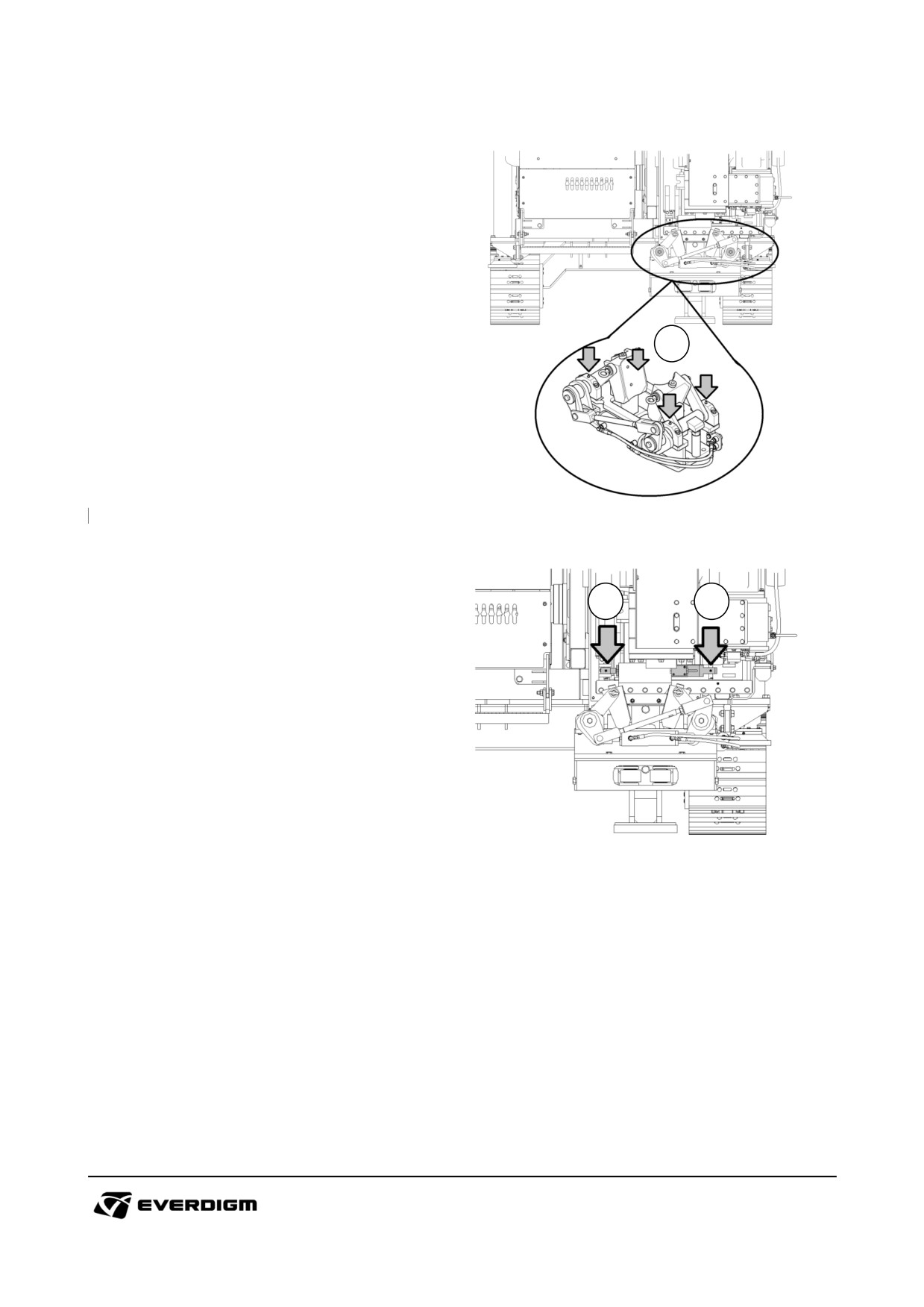
Link on foot clamp
① Link on foot clamp (4 places)
1
Side shift cylinder
① Side lift cylinder (right) (1 place)
② Side lift cylinder (left)
(1 place)
1
2
60
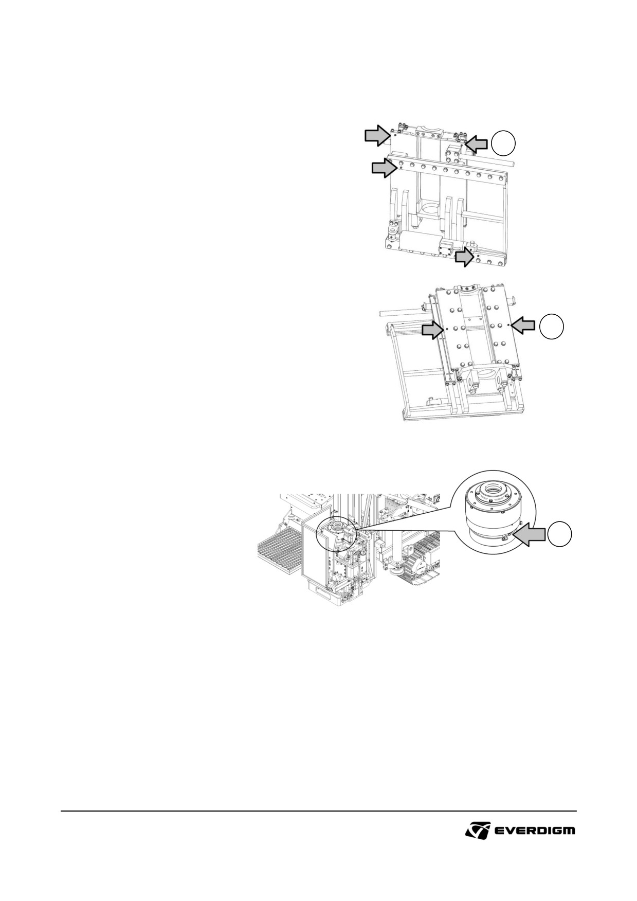
Rotary head cradle
1
① Front side on cradle (4 places)
② Rear side on cradle (2 places)
2
Chuck
① Chuck (1 place)
1
61
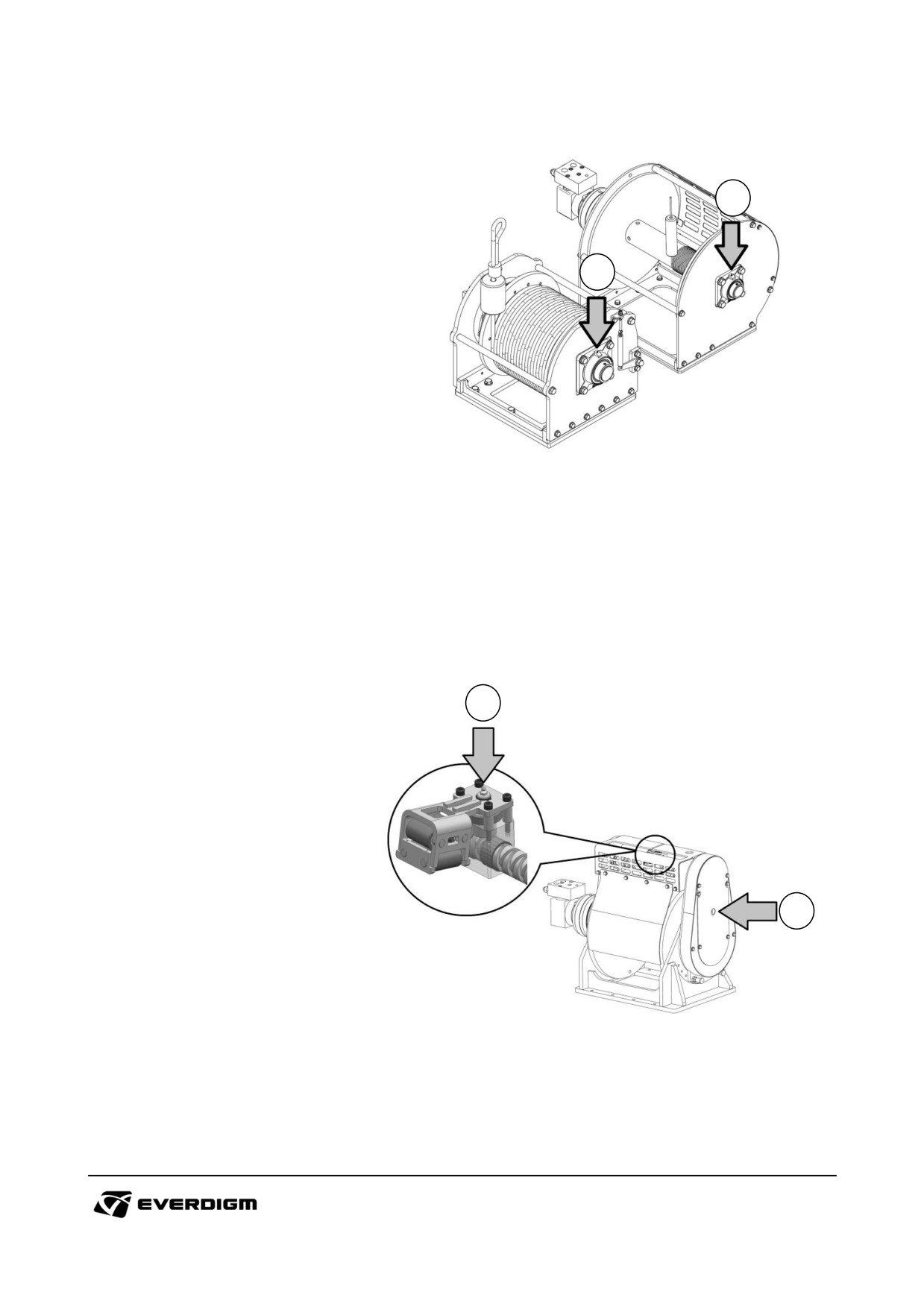
Wire line winches (Standard)
① Outrigger pad (4 places)
2
1
1
Level winder (Option)
① Screw bracket (1 place)
② Drum (1 place)
2
62
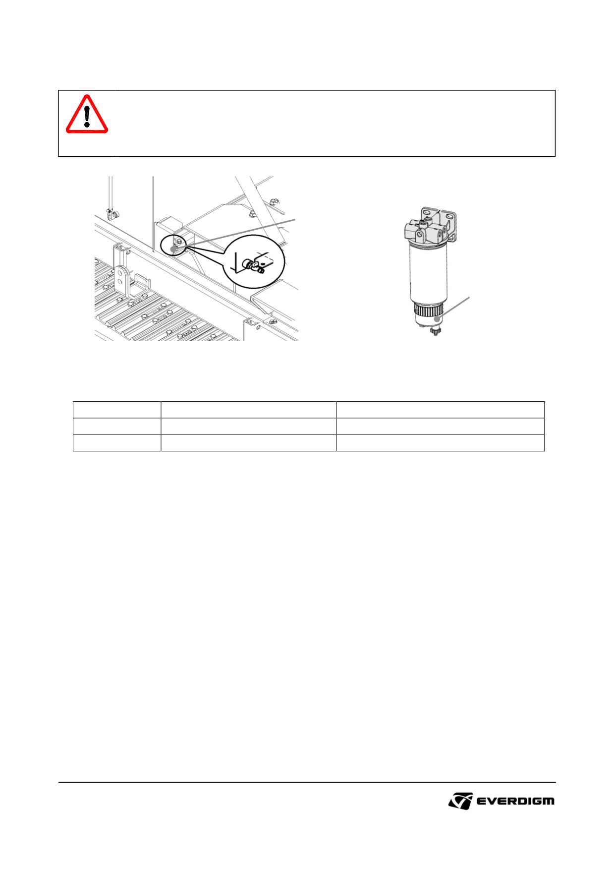
4.1.3 Water drain on fuel
IMPORTANT!
Contained water or impurities on fuel will cause serious damages on engine and related
parts. It is recommended drain water on the fuel tank and water separator before starting
engine.
1
2
Figure: Fuel drain cock
Figure: Fuel-Water separator
Table: Water drain on fuel
Check point
Parts
Instruction
1
Fuel drain cock
Open drain cock and drain water
2
Fuel-water separator
Open drain cock and drain water
63
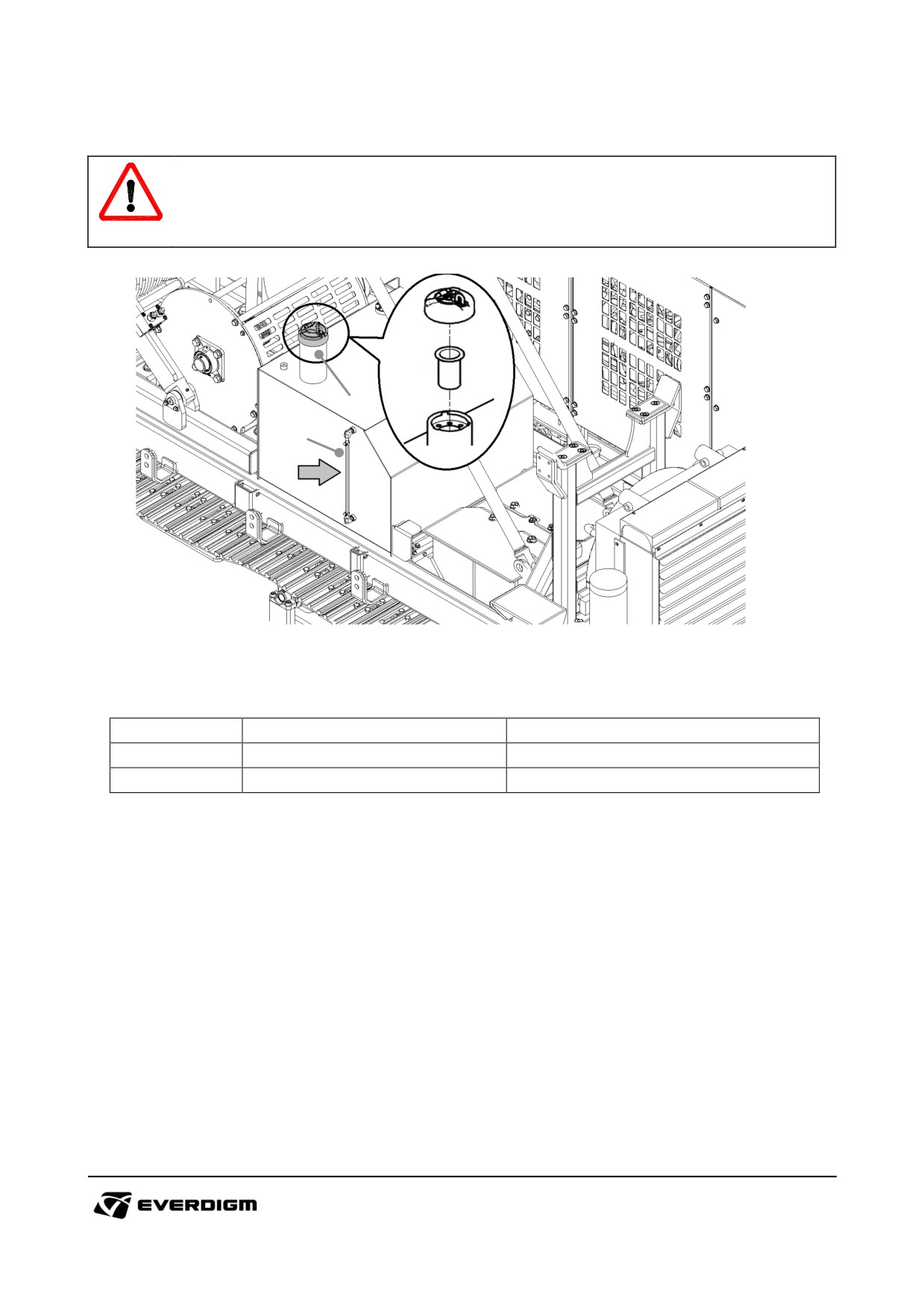
4.1.4 Fuel level check
WARNING!
The fuel is flammable. Avoid heat, fire and electricity during refilling fuel.
Stop the engine during refilling fuel.
2
1
Figure: Fuel level check
Table: Fuel level check
Check point
Parts
Instruction
1
Fuel level indicator
Check remained fuel on the tank
2
Fuel cap
Open fuel cap and refill the fuel.
64
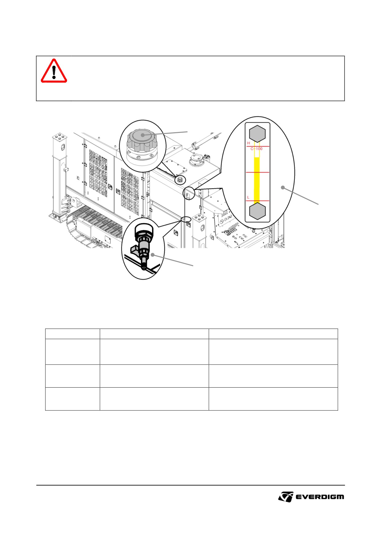
4.1.5 Hydraulic oil level check
WARNING!
Do not mix with other type of hydraulic oil.
Check oil contamination and water insertion regularly, and replace hydraulic oil according to
maintenance schedule.
2
1
3
Figure: Hydraulic oil tank
Table: Hydraulic oil level check
Check point
Parts
Instruction
Check remain amount of hydraulic
1
Hydraulic oil level gauge
oil, and refill it if required.
2
Hydraulic oil tank cap
Refill hydraulic oil if required.
3
Hydraulic oil drain cock
Drain hydraulic oil if required.
65
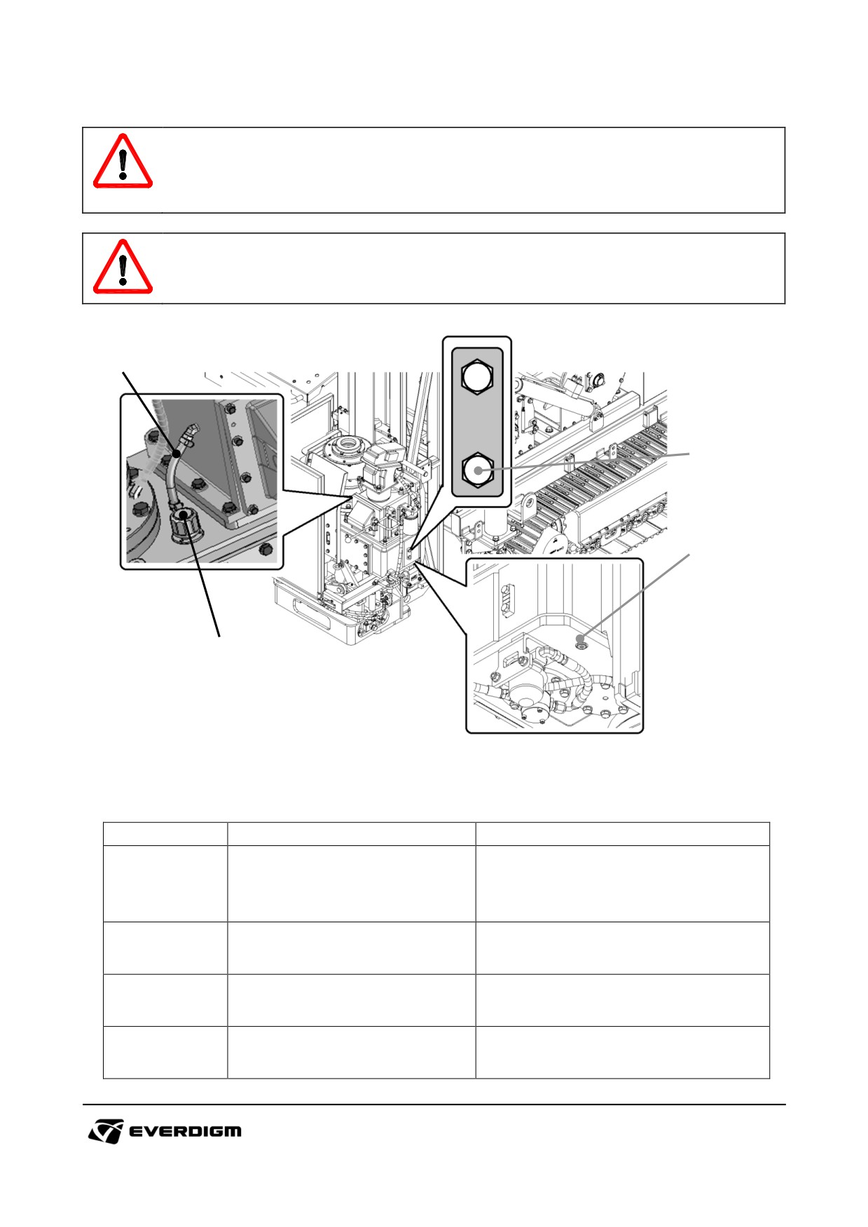
4.1.6 Rotary head lubrication oil
WARNING!
Lack of drifter lubrication oil will cause early wear or damage of drifter rotation parts.
Too much lubrication oil will cause excessive heat on the rotary head.
DANGER!
Do not run rotary head while maintenance is performed.
4
1
1
2
3
Figure: Rotary head check points
Table: Rotary head check list
Check point
Parts
Instruction
Open plug and check if oil comes
out from the hole. A little oil comes
1
Oil level check plug
out from the hole, it is OK to
operate.
If too much oil is existed in the gear
2
Oil drain plug
box, drain oil by opening drain plug
When rotary head is operated, check
3
Oil circulation check hose
the oil condition which is circulated
correctly.
If oil is not filled sufficiently on the
4
Oil refill cap
rotary head, open the cap and fill the
lubrication oil.
66
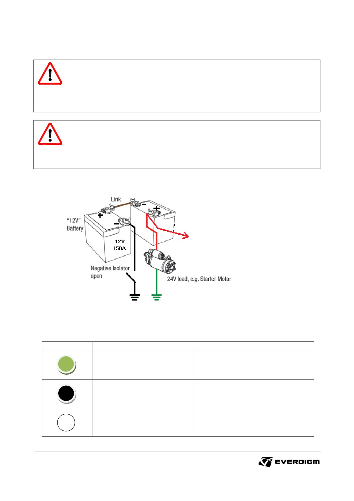
4.1.7 Electric device check
DANGER!
Gas from battery may be explosive.
When liquid of battery is contacted with skin or eye, clean it immediately with clean water, and
consult with doctor.
Do not touch electric devices with bare hands. Turn off master switch before repairing.
WARNING!
Before welding, turn off master switch and disconnect battery. Exposing high voltage may
burn electric lines and devices.
If abnormal condition is noticed during checking procedure, shut off main switch and repair
failed parts for safe operation.
Battery check
Figure: Battery connection
Table: Indicator on battery
Indicator
Condition
Check point
Normal
OK to use
Low battery. Charging is required.
Need to charge
If
indicator shows 'black' after
recharging, replace battery.
Need to replace
Replace battery with new one
67
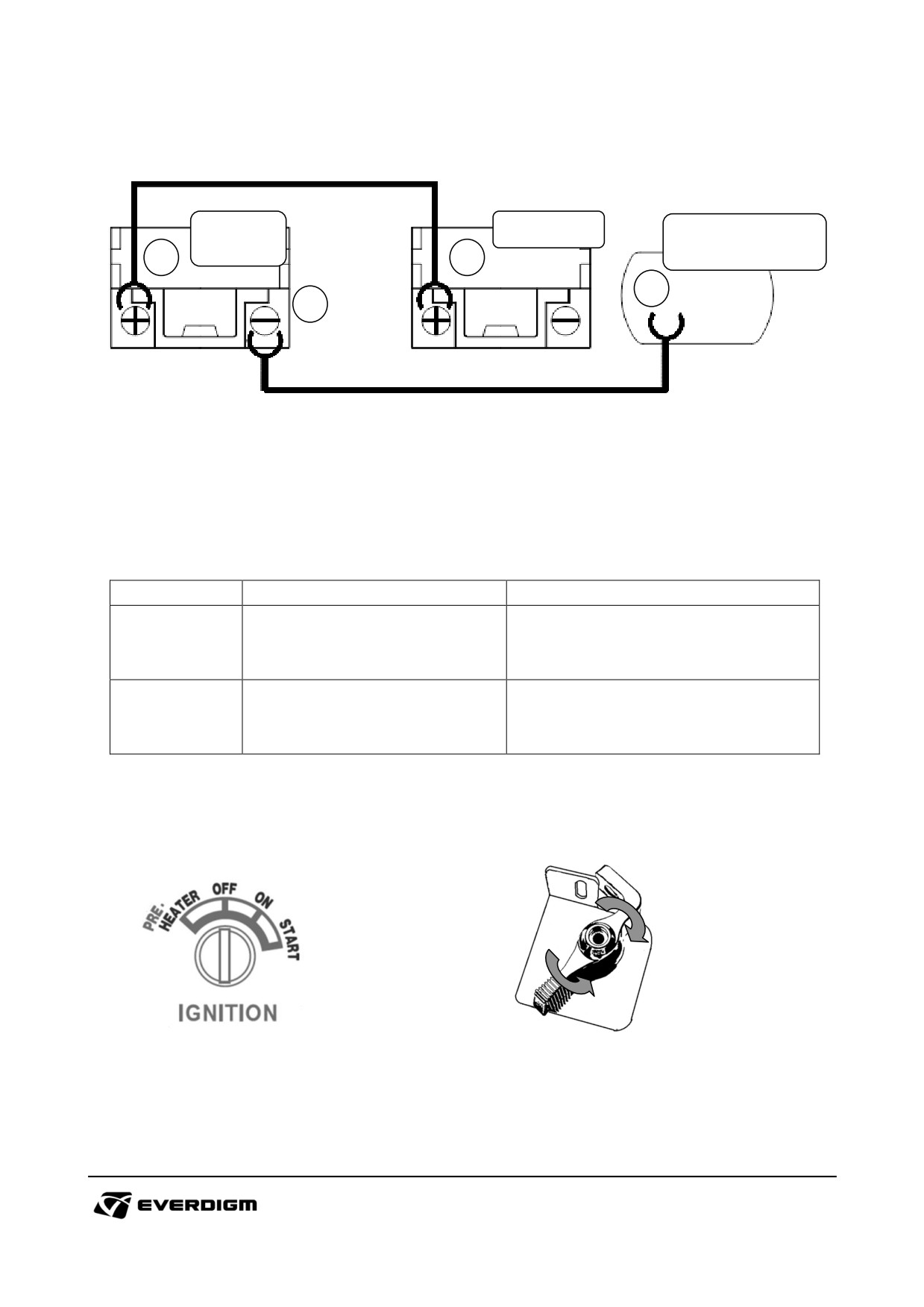
Battery recharge procedure
Rescue
Low battery
Engine Block
Vehicle
< Machine>
2
1
4
3
Figure: Battery connection for recharging
* Electric cable connection order (for recharging battery)
:
① → ② → ③ → ④
* Electric cable disconnection order (after recharging)
:
④ → ③ → ② → ①
Table: Main control panel
Check point
Parts
Instruction
Check if electric cables are loosen
-
Electric cables
or damaged
Plastic cover damage
Check if connections are loose or
-
Electric connection port on battery
rusted.
Turn on electric system
Figure: Engine starter switch
Figure : Master switch (2 places)
① Turn on master switches in bonnet
② Turn engine starter key to "ON" position
68
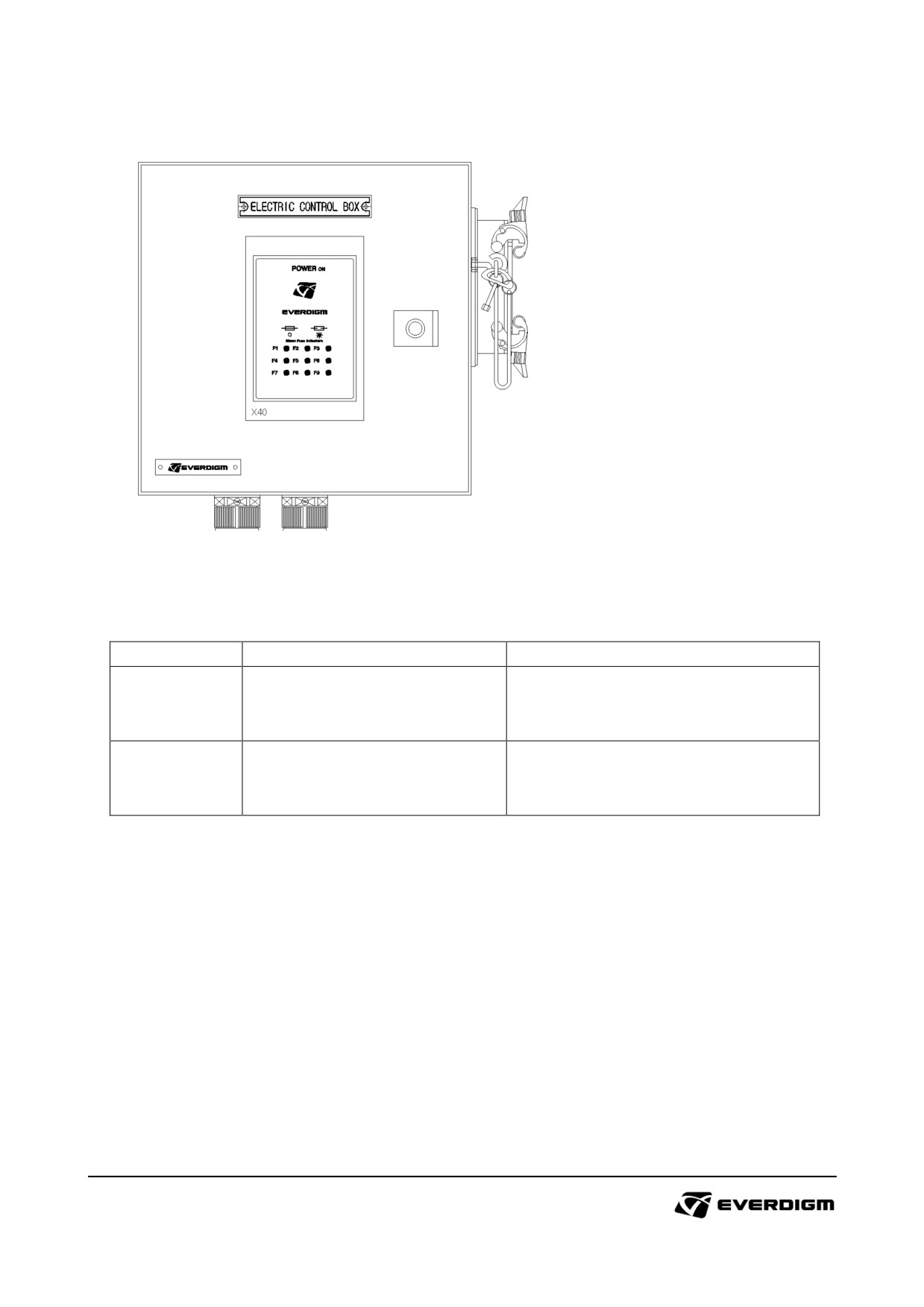
Main control panel
Figure: Main control panel
Table: Main control panel
Check point
Parts
Instruction
Check if fuse or relay lamp is ON.
-
Main control panel
If lamp is ON, replace fuse or relay.
Check electric cables and connector
-
Electric connection
whether it is damaged or rusted.
69
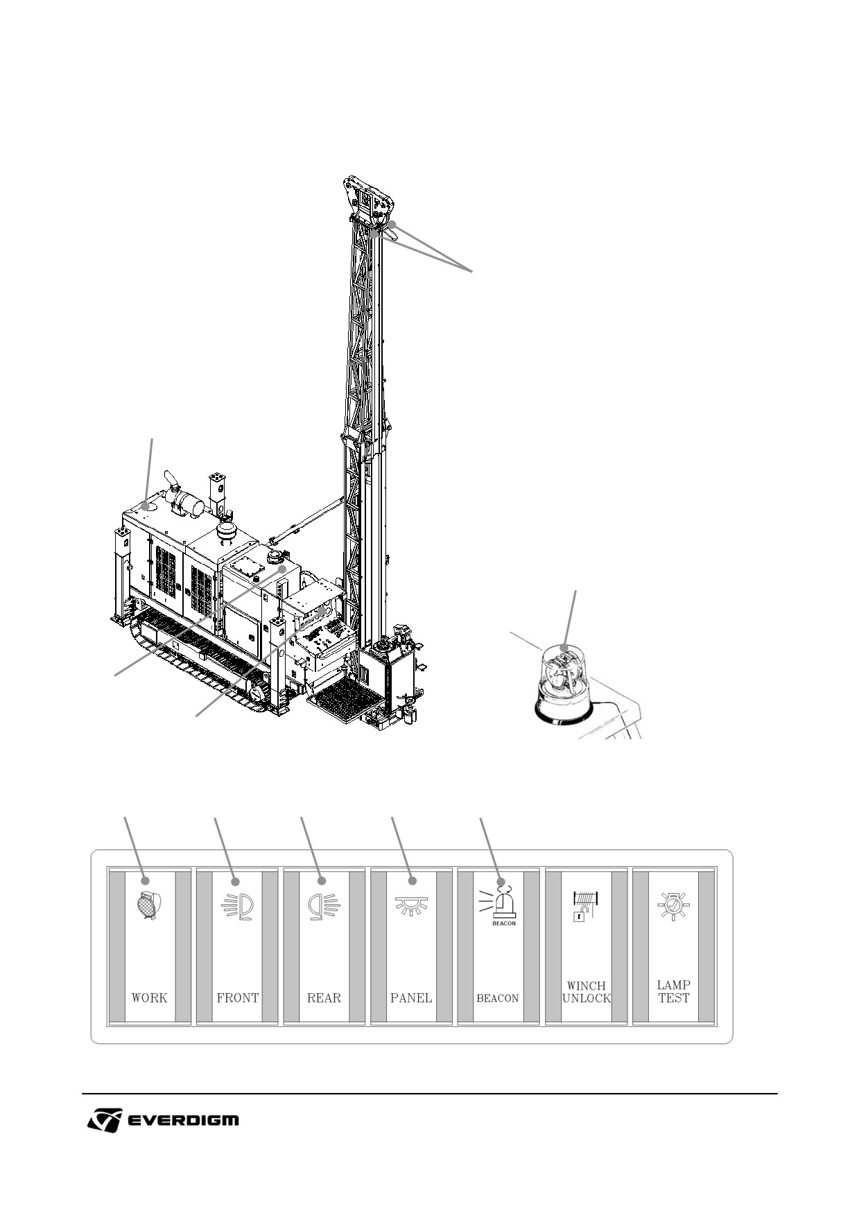
Working lights and rotating beacon
1
3
5
2
4
Figure: Work lights
Figure : Rotating beacon
1
2
3
4
5
Figure: Lights and Rotating beacon control switch
70
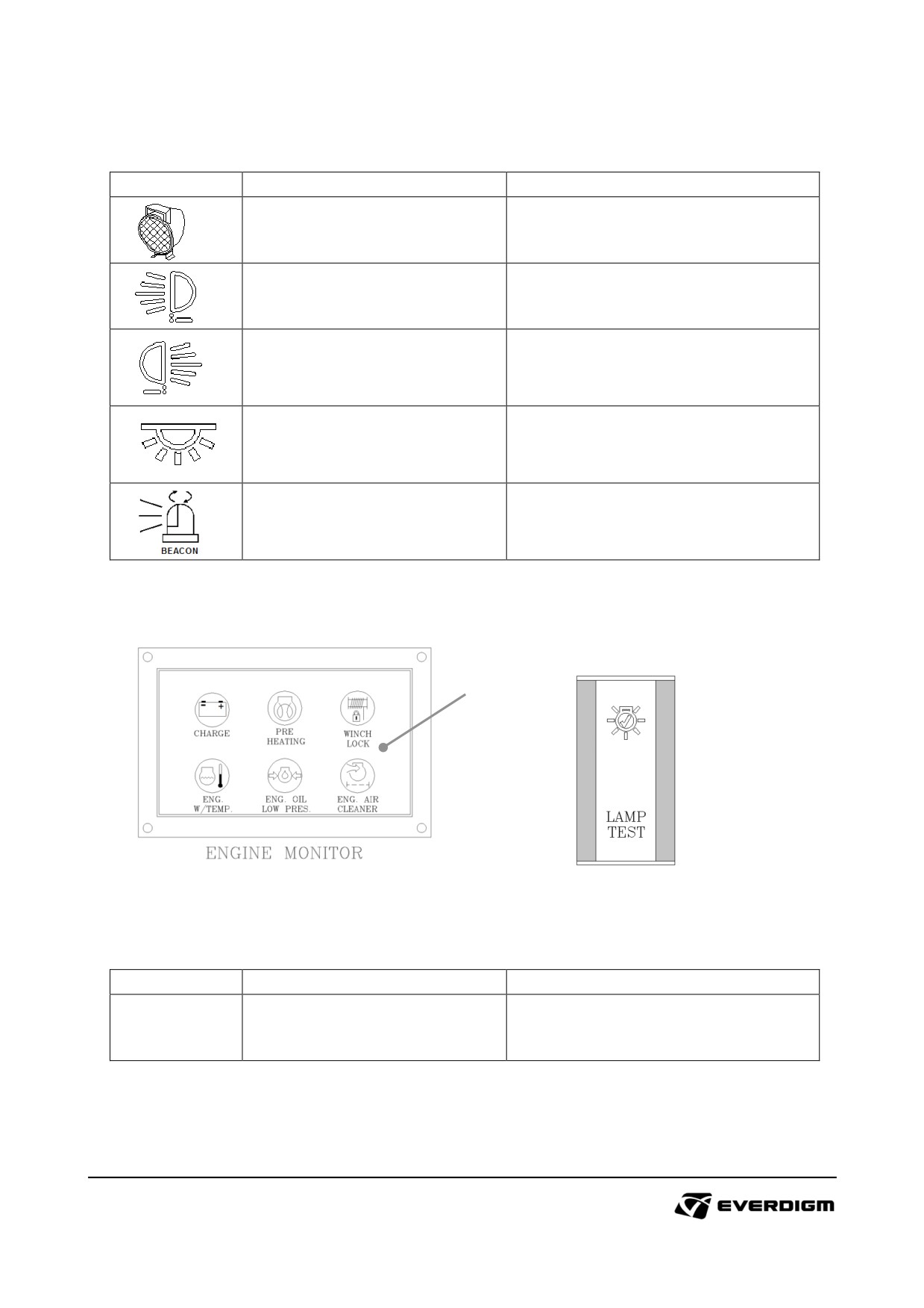
Table: Working lights and rotating beacon
Symbol
Parts
Instruction
Push working light switch and check
1. Working light (Mast, 4 pcs)
lamp if lights are ON.
Push working light switch and check
2. Working light (Front, 1 pc)
lamp if lights are ON.
Push working light switch and check
3. Working light (Rear, 1 pc)
lamp if lights are ON.
Push working light switch and check
4. Working light (Panel, 1 pc)
lamp if lights are ON.
Push rotating bacon switch and check
Rotating beacon (Rear, 1 pc)
lamp if lights are ON.
Lamp test
1
Figure: Diagnostic lamp
Figure : Lamp test
Table: Lamp test
Check point
Parts
Instruction
Push lamp test switch and check all
1
Lamp test and diagnostic lamp
diagnostic lamps are ON.
71
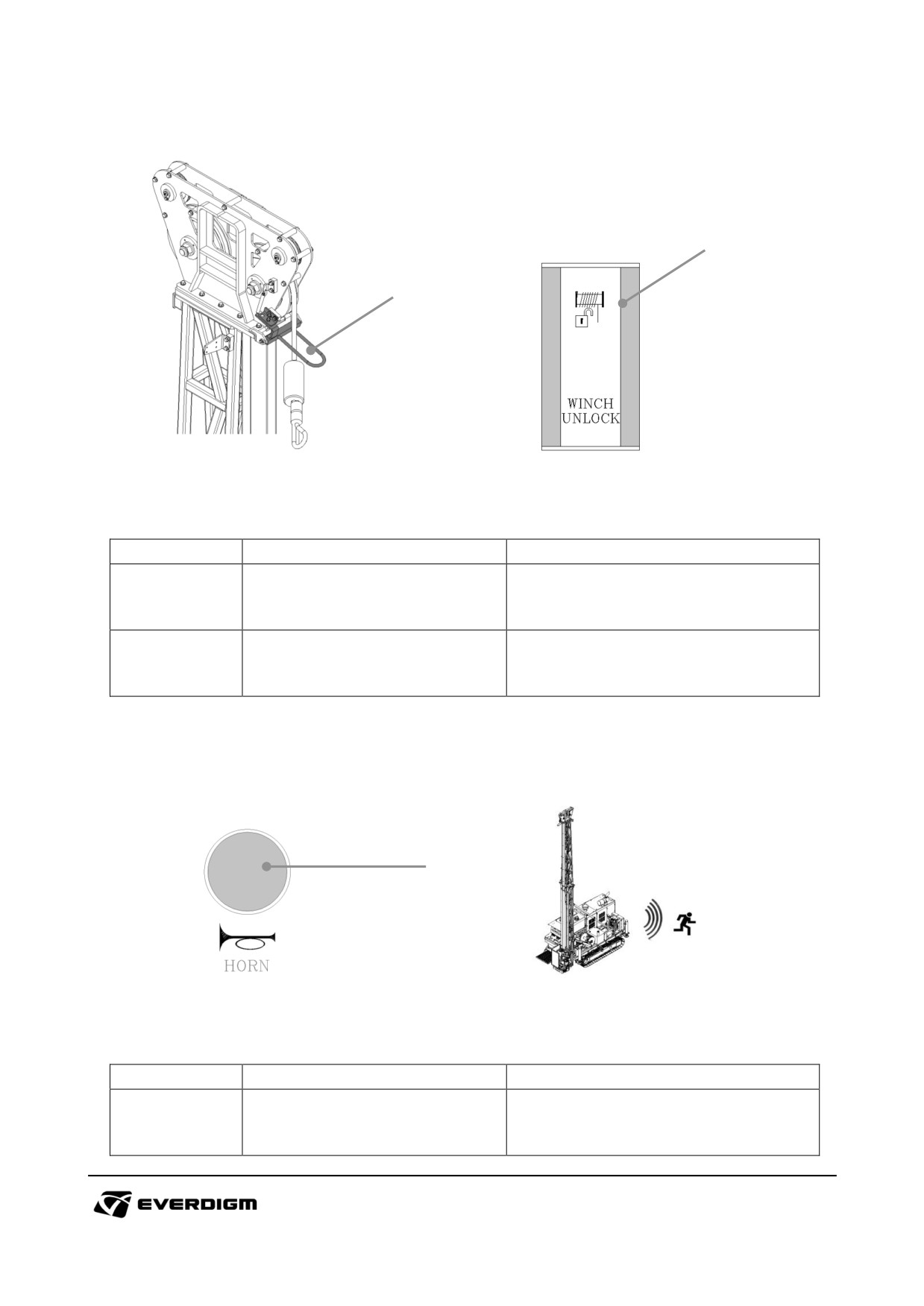
Winch unlock switch
1
1
Figure: Upper hoist limit
Figure : Winch unlock switch
Table: Lamp test
Check point
Parts
Instruction
When main line wire weight hits the
1
Upper hoist limit
upper hoist limit, the main line winch
is stopped automatically.
When upper hoist limit sensor is
2
Winch unlock switch
activated, this switch enable to
operate main wireline winch.
Horn switch
1
Figure: Horn switch
Table: Horn switch
Check point
Parts
Instruction
Push horn switch and check sound if
1
Horn switch
it is enough loud to alert to others.
72
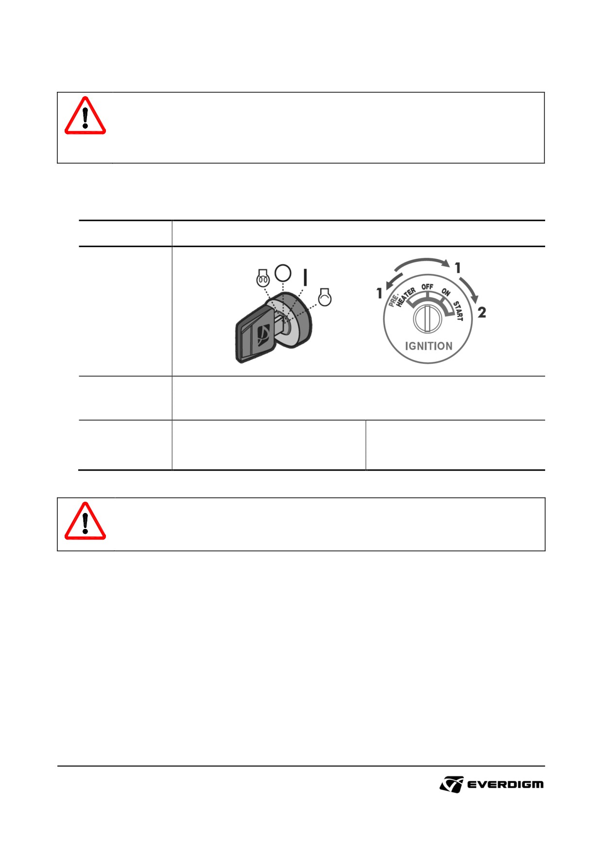
4.2. Engine start
WARNING!
Check inner side of bonnet before starting engine. Tools and any other objects on the engine
room may cause serious damage.
Alert to others before starting engine.
4.2.1 Starting engine
Engine type
Instruction
Starter key
configuration
15˚C or above
Turn starter key and hold for 3 seconds "ON" position.
(ambient
Start engine and release key after starting
temperature)
0˚C or below
Hold starter key "PREHEATER"
(ambient
Hold starter key "ON" position for 10
position for
10 seconds before
temperature)
seconds before staring engine.
staring engine.
IMPORTANT!
Do not set high engine RPM immediately after starting engine. Warming up the engine and
equipment properly before operation.
Warm up the equipment and engine with idle rpm at least 3 minutes before operation.
Check equipment condition after starting engine.
When abnormal engine condition is noticed, contact local engine distributor for more support.
73
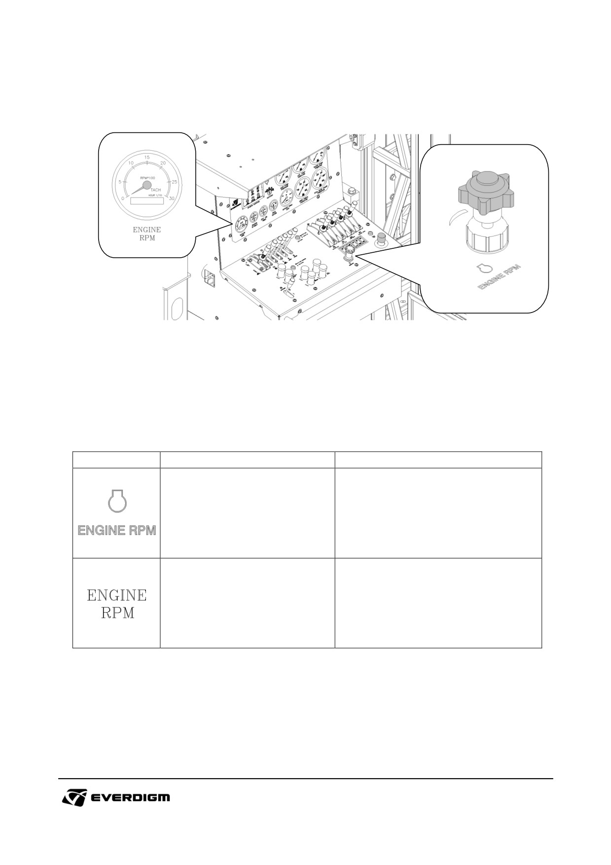
RPM Throttle control
Figure: RPM throttle switch
According to working condition of drill rig, the engine rpm can be controlled and adjusted by rotating
switch.
Table: RPM throttle control switch and max. rpm mode selection switch
Symbol
Description
Engine rpm range (rpm)
Engine RPM Throttle control switch
1,000 (Idle) ~ 2,200 (Max)
It shows current running engine rpm.
Engine RPM tachometer
Also, engine hour is indicated on
this tachometer.
74
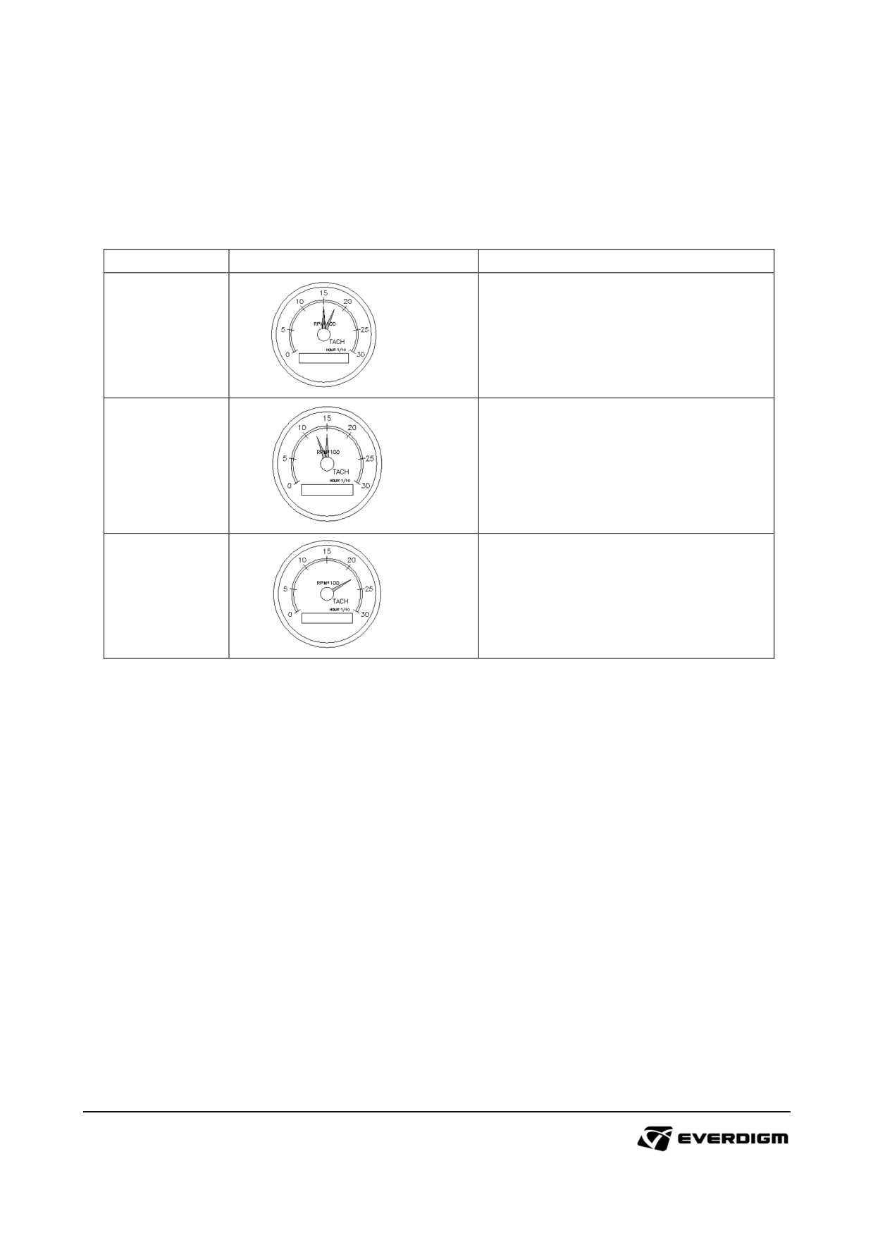
For the efficient work, the following is reference for optimal operation. Operator may set engine RPM
manually according to working condition.
Table: Proper engine RPM range for operation
Operation
Proper RPM Range
Remarks
Increase engine RPM when more
Traveling
torque and speed is required
1500 ~ 1700
Mast
Adjust engine RPM for precise
positioning
movement.
1300~1500
According to pipe size, adjust the
Drilling
engine rpm with optimal bit rotation
speed.
2200
75
4.2.2 Emergency switches
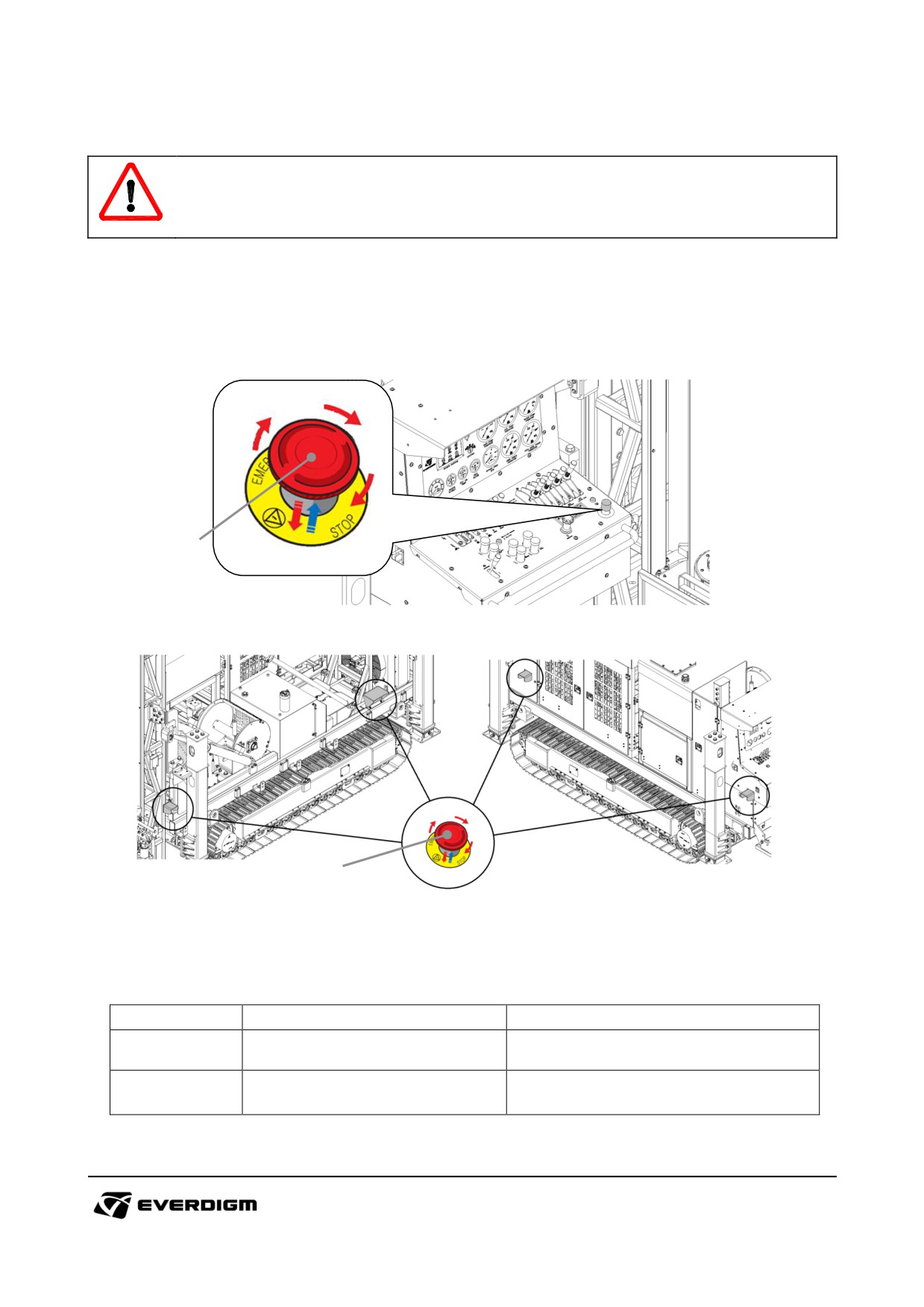
IMPORTANT!
Emergency switches should be checked regularly. When danger situation is noticed, stop the
machine immediately.
When engine would not run, check emergency switches if it is activated.
Emergency switch on control panel
1
Figure: Emergency switch on the control panel
2
Figure: Emergency switch on side bonnet (4 places)
Table: Emergency switches
Check point
Parts
Instruction
Push button and check if engine is
1 & 2
Emergency button push
stopped.
Turn button and check if engine
1 & 2
Emergency button turn
starts normally.
76
4.3. Engine stop and parking
IMPORTANT!
Do not stop engine when it has high RPM.
Before stop the engine, set idle RPM for 30 seconds. Sudden engine stop on high RPM will
cause engine failure or damages.
4.3.1 Parking
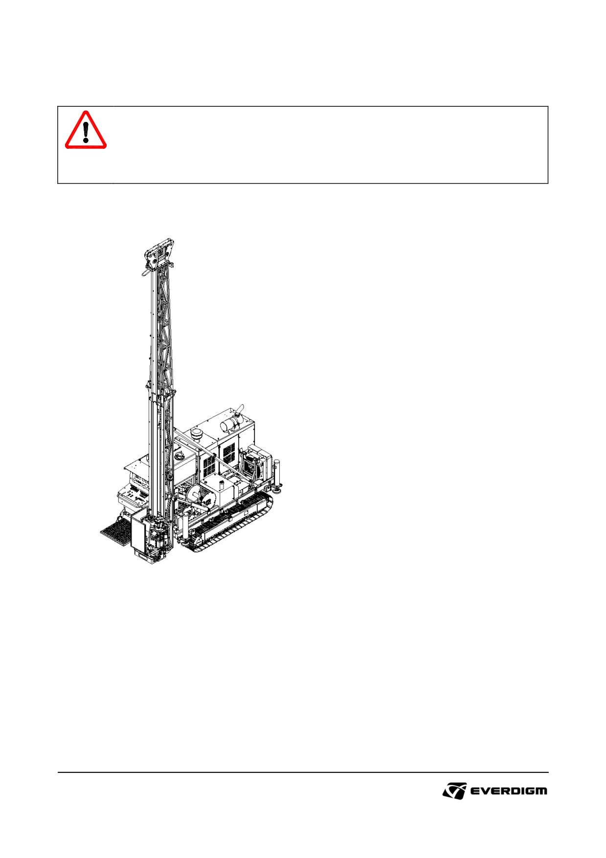
Figure: Parking posture of machine
① Place machine on the safe, firm and even ground. Do not put the machine on slope.
② Put the mast on firm ground with vertical position.
77
4.3.2 Engine stop
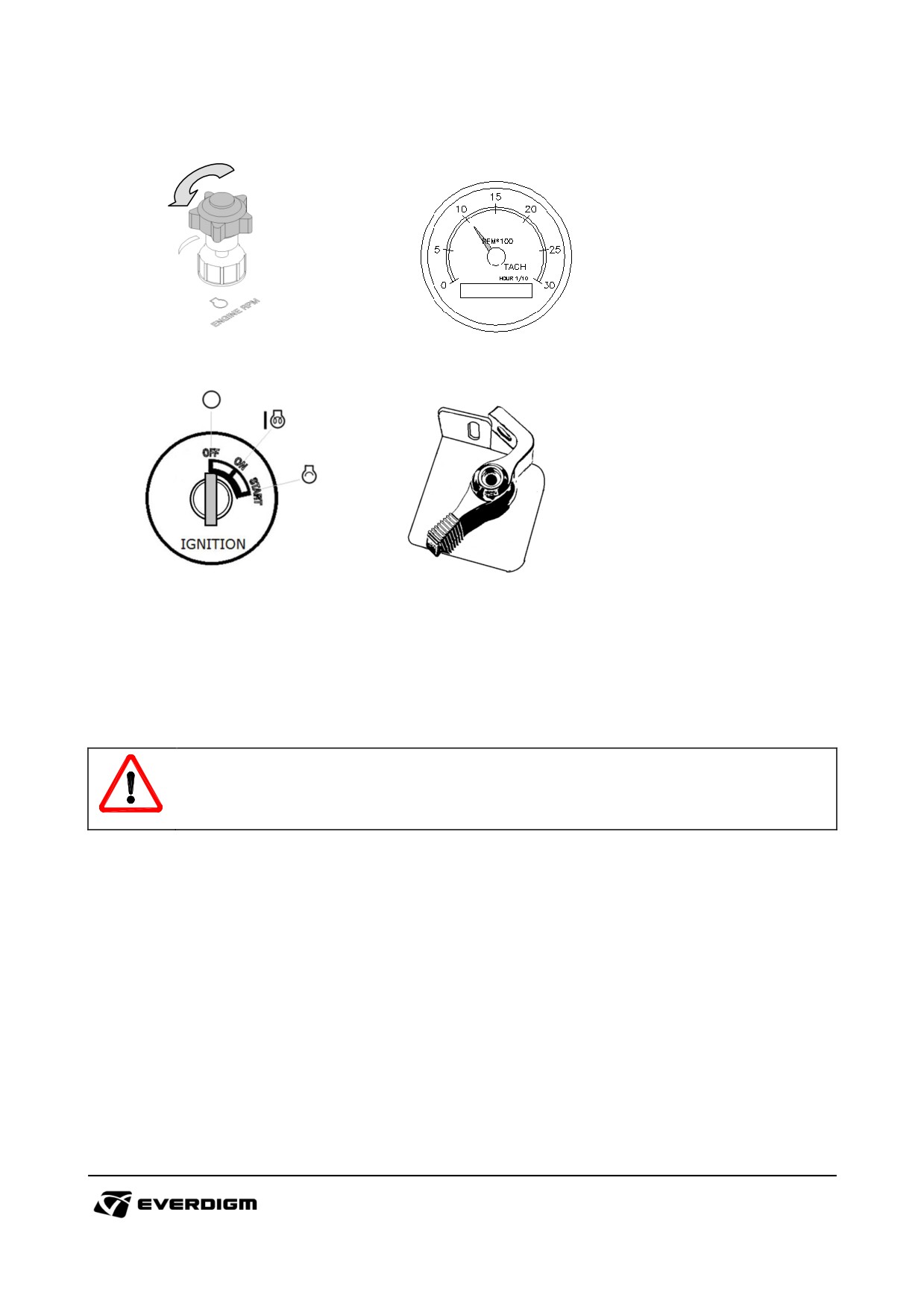
Figure: RPM throttle lever
Figure : Idle engine RPM
Figure: Engine starter switch
Figure : Master switch
① Set the engine RPM to idle mode (1000 rpm), and wait for 30 seconds
② Turn off all switches and set the levers to neutral position in the cabin
③ Turn engine starter key to "OFF" position
④ Turn off master switch in bonnet
(O : off, I : on)
IMPORTANT!
Do not stop the engine in high engine RPM except emergency. Before stopping engine, set
idle rpm for 30 seconds.
78
4.3.3 Locking the machine
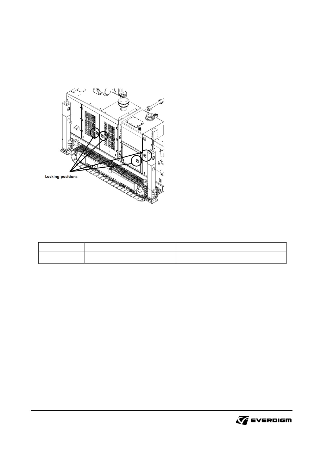
Figure: Locking on machine
Table: Locking positions
Check point
Parts
Instruction
-
Bonnet locking
Lock the doors.
79
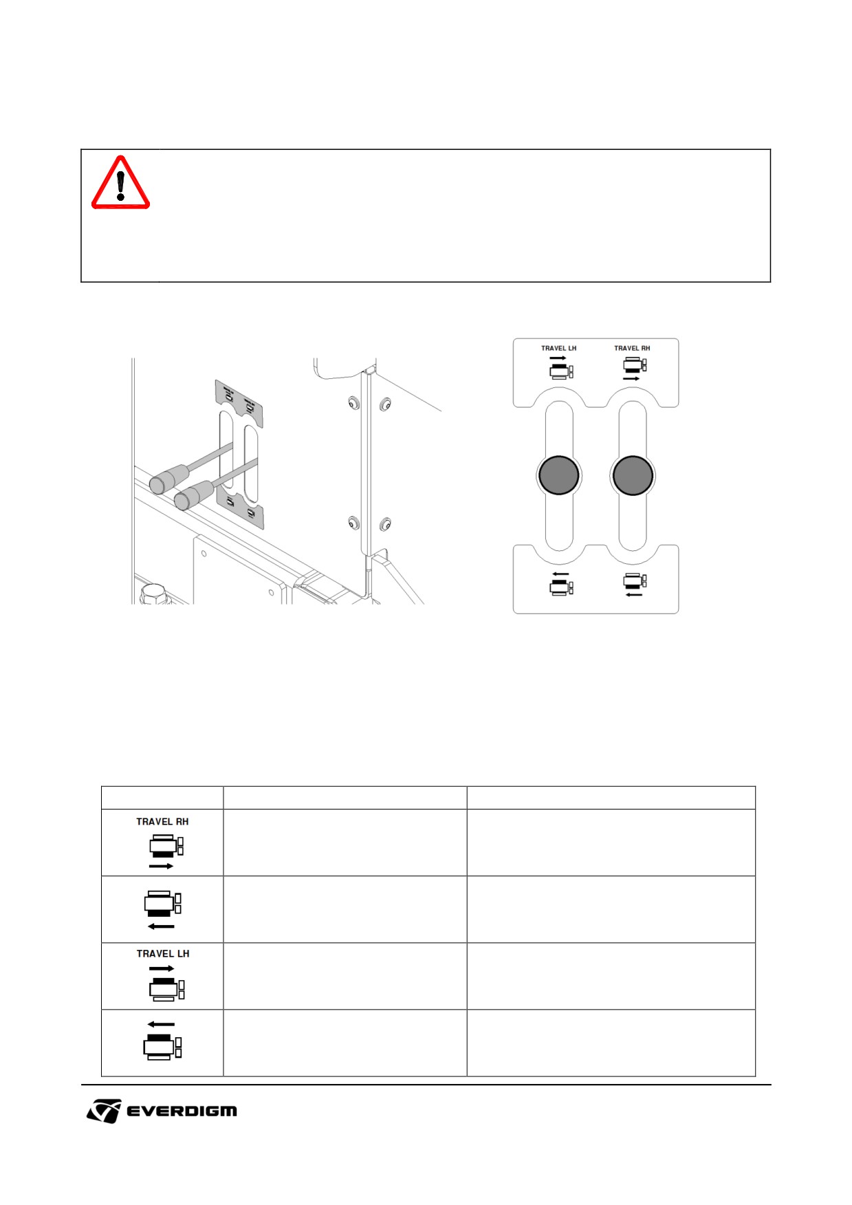
4.4. Traveling
DANGER!
Do not allow others to approach to the machine while it is traveling.
Pay attention on ground condition while it is moving. Do not attempt to move the machine
where danger situation is predicted.
Pay special attention to your feet while machine is moving.
4.4.1 Travel control
Figure: Travel lever
Travel lever has proportional control which means the travel motor speed can be adjusted according to
how much lever is pushed or pulled.
The travel speed can be increased or decreased by engine RPM settings.
Symbol
Parts
Instruction
Travel control lever (Right, Forward)
Right track forward movement
Travel control lever (Right, Backward)
Right track backward movement
Travel control lever (Left, Forward)
Left track forward movement
Travel control lever (Left, Backward)
Left track backward movement
80
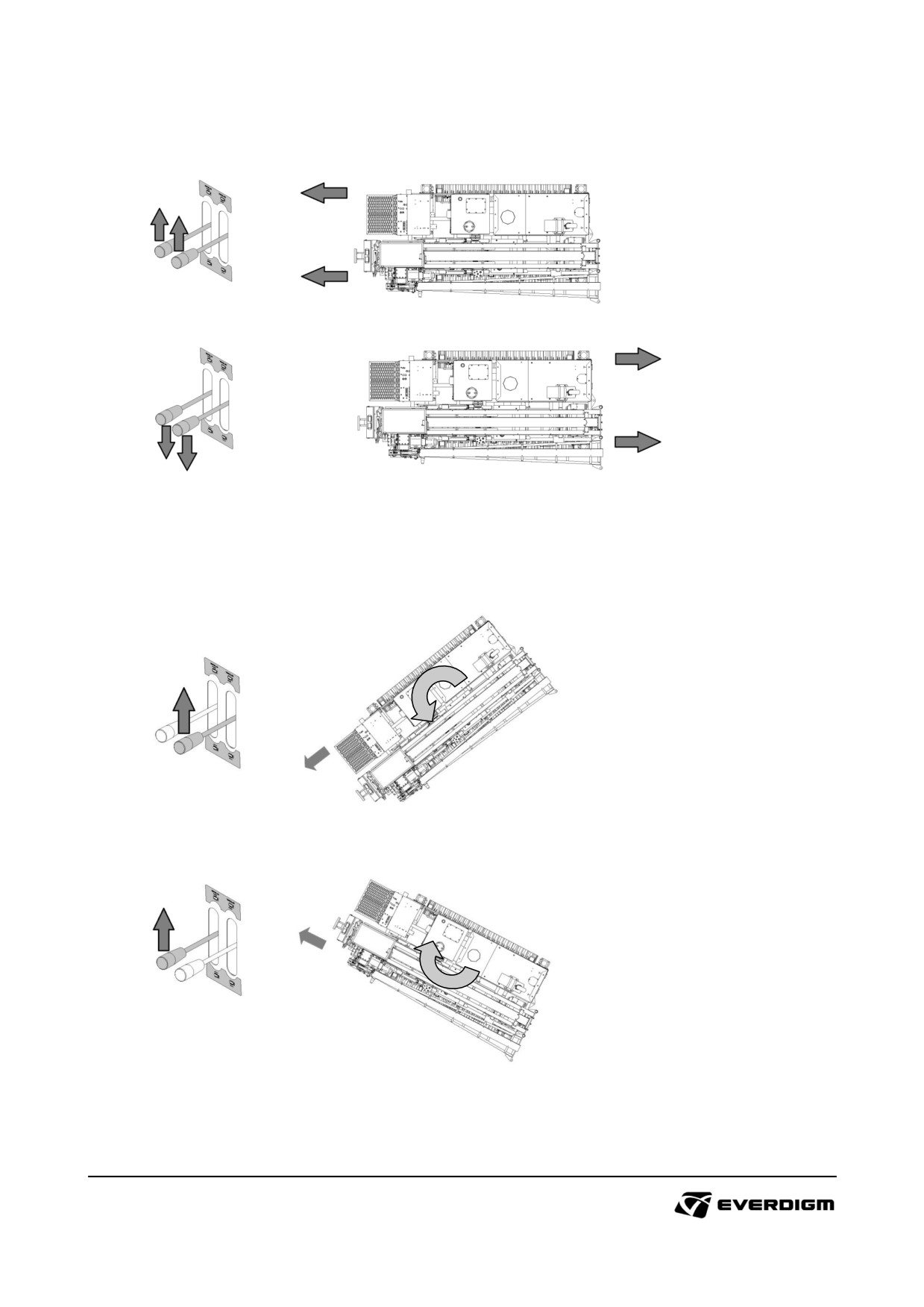
Forward and backward movement
Figure: Forward and backward movement
Pull up or pull down both travel levers (L and R) for moving the machine to forward or backward.
Left and right turn
Figure: Left or right turn
Pull up or pull down one lever (L or R) for turning the machine.
81
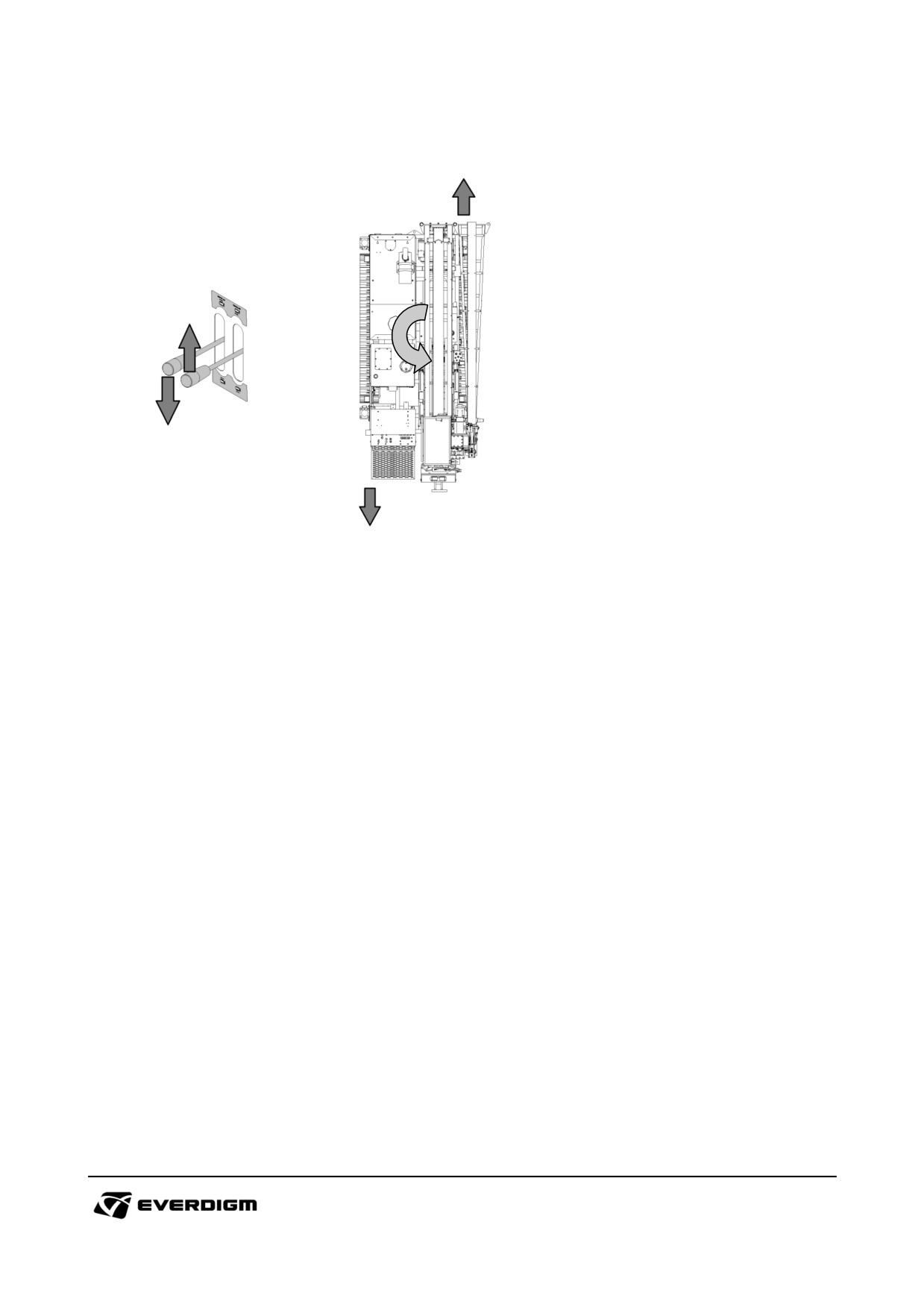
Spin turn
Figure: Spin turn
Machine can make sharp turn in the arrow area by pushing or pulling the levers (L and R) to opposite
sides.
82
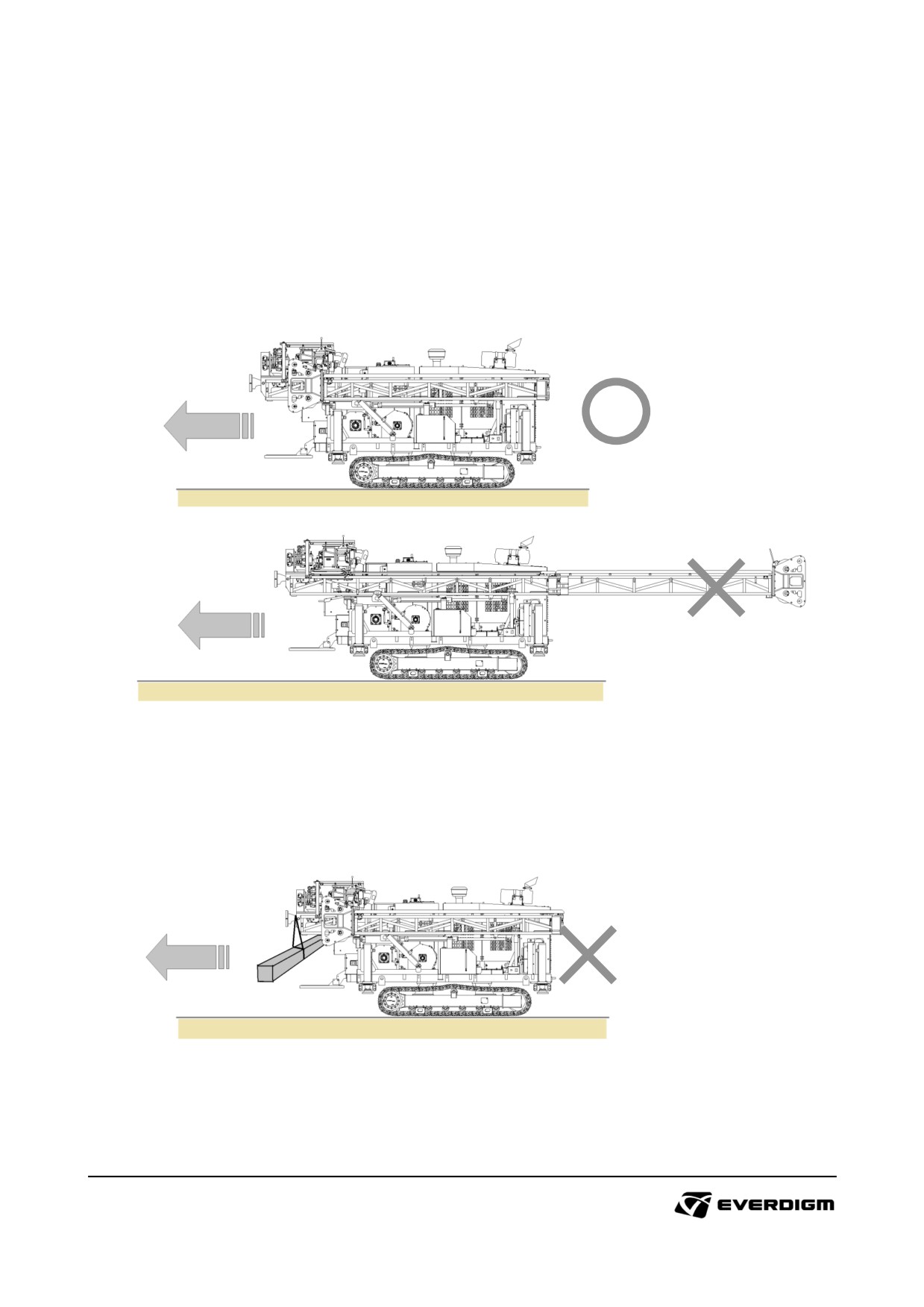
4.4.2 Correct posture for moving equipment
Machine posture before moving
Fold upper mast with lower mast and put the mast on the supporter firmly. Mast and related parts
should not move freely on uneven ground while machine is traveling.
Check ground condition where the machine will move.
Do not carry heavy object with machine
Carrying heavy objects will break down the balance of machine, and cause damage or deformation of
components.
83
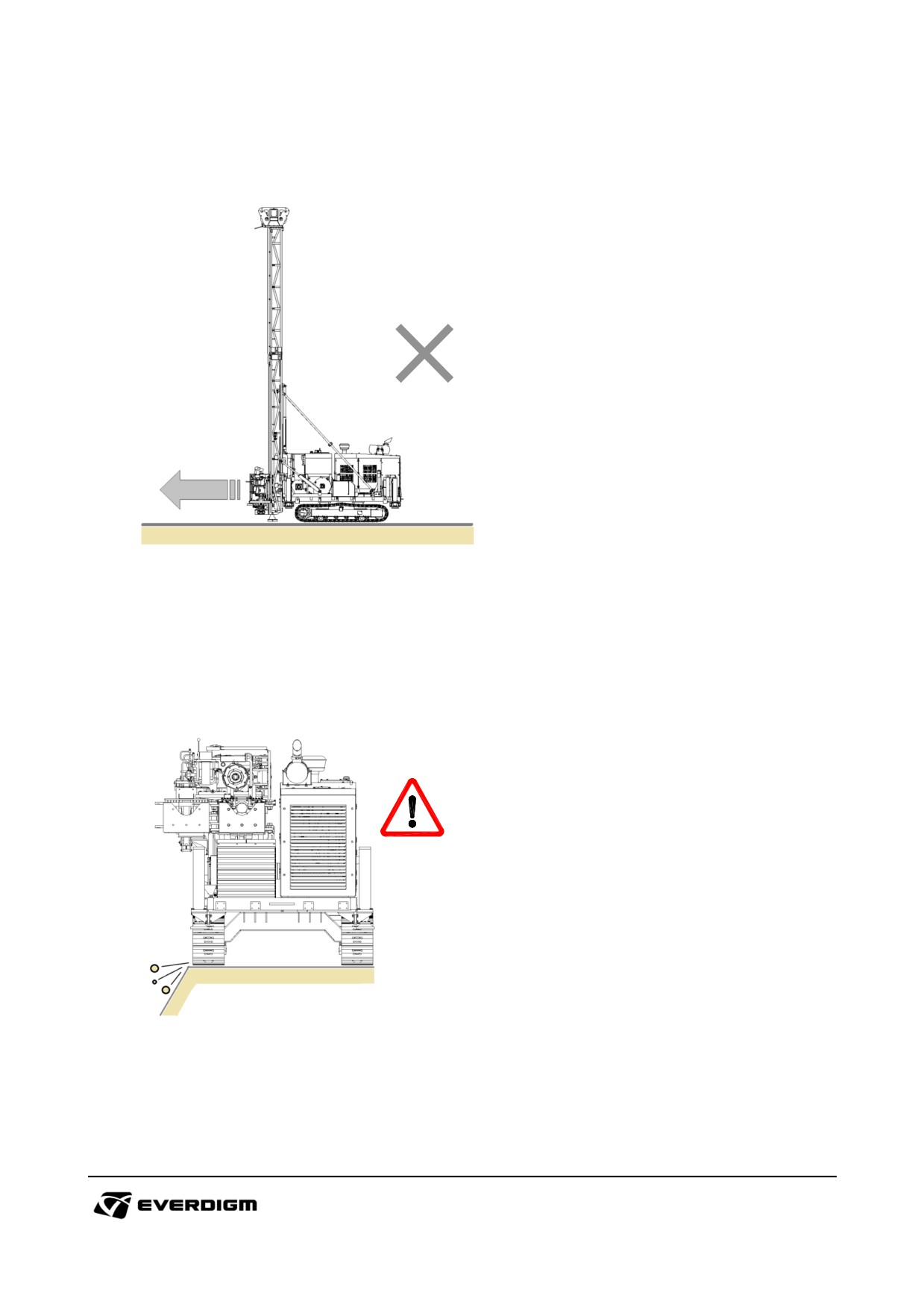
Do not move machine with mast in the air while traveling
External shock or bending stress will cause damage to the machine.
Pay special attention while traveling narrow area
The slope and ground may not be strong enough to support machine. Check track location while
driving narrow area.
84
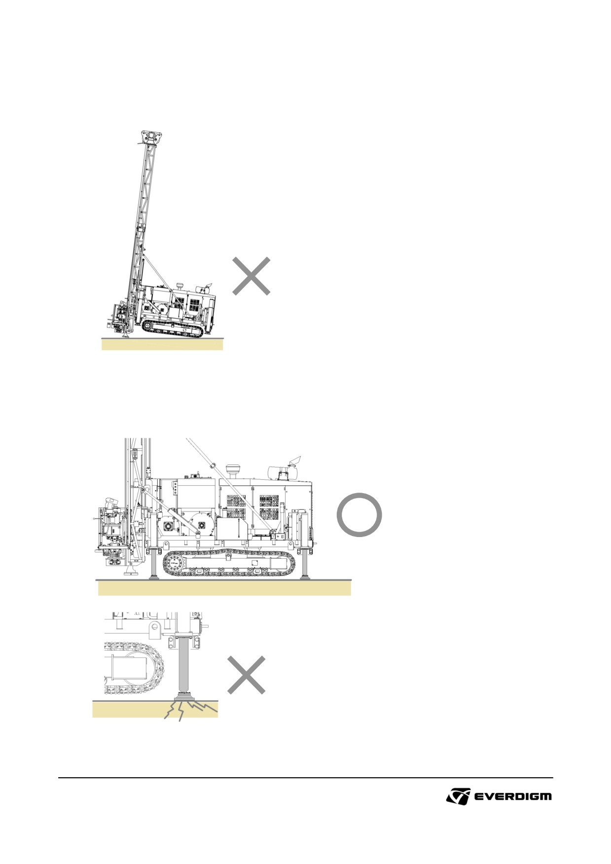
During operation
Do not support machine or press mast with excessive force. It will cause damages to the machine.
The machine should be securely supported with 4 outriggers during operation. The outriggers should
be settled on the strong and firm ground.
85
4.5. Controller and switches
DANGER!
Do not allow others to approach to the machine while it is operating.
Wear ear plug, safety helmet, mask and safety glass for your safety. High noise during drilling
can hurt your hearing, and rock powder will be very harmful to your health.
Pay attention to the moving parts. It may hit machine or other objects.
4.5.1 Before operation
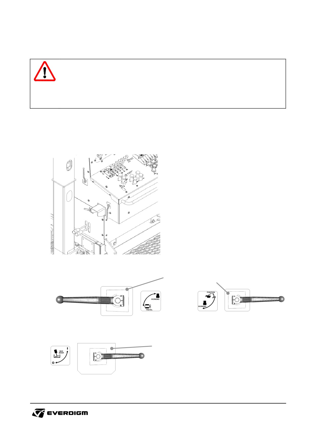
Check work mode selection levers
Check work mode by lever location.
Figure: Work mode selection levers, and mud mixer ON / OFF lever
1
2
Figure: Travel and drilling mode selection levers
Figure: Positioning and drilling mode selection levers
3
Figure: Mud mixer ON / OFF lever
86
Table: Work mode selection levers, and mud mixer ON / OFF lever
Check point
Parts
Instruction
Drilling mode and travel mode
selector lever:
Drilling mode : Rotary head, Feed,
Travel and drilling
Main winch, Wireline winch
1
mode selection levers
Travel mode : Travel motors
When one of the two modes is
selected, the other one is disabled.
Drilling mode and positioning mode
selector lever:
Drilling mode
:
Water pump,
Mud mixer
Positioning and drilling
2
mode selection levers
Positioning mode : Mast raise, mast
dump, outrigger
When one of the two modes is
selected, the other one is disabled.
3
Mud mixer ON / OFF lever
Mud mixer operating switch
87
Water pump and mud mixer
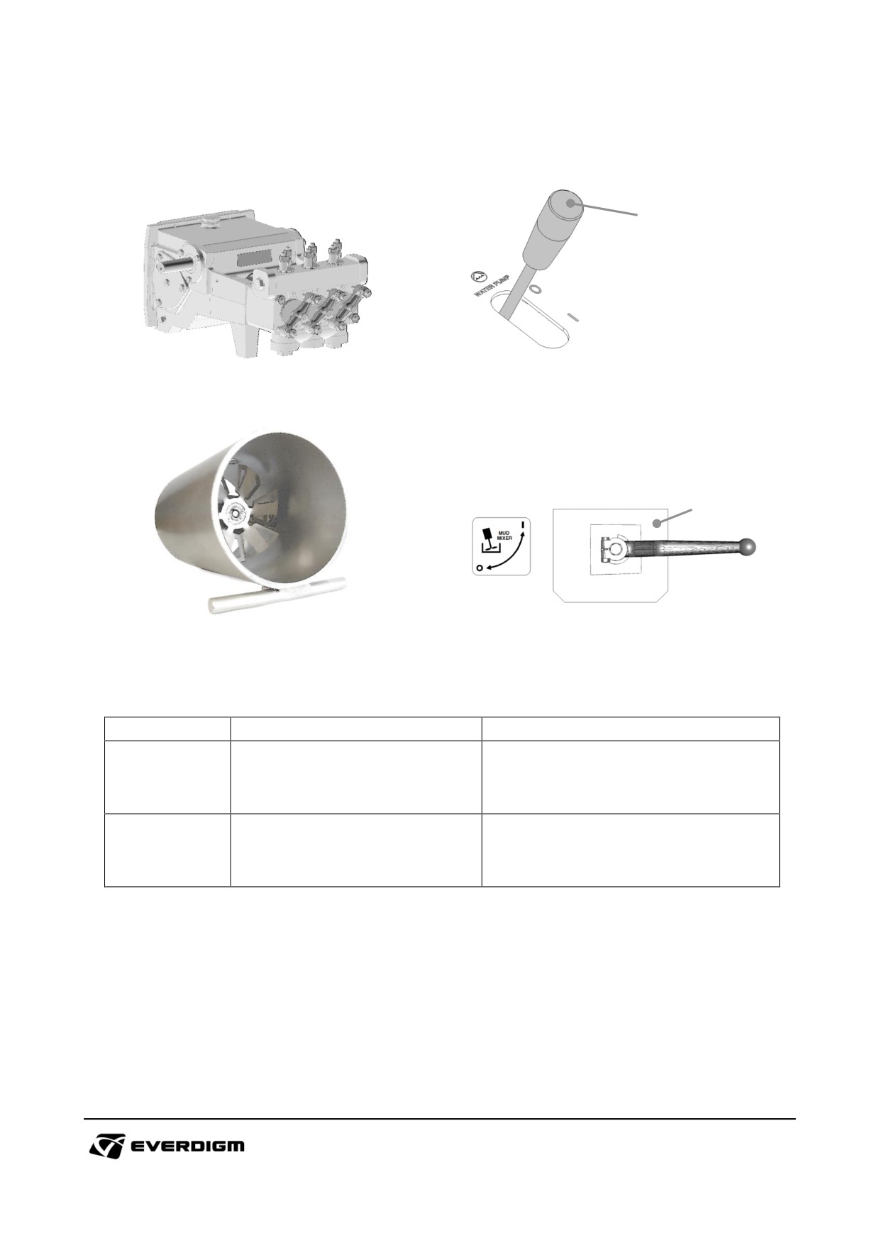
Check water pump and mud mixer operating condition.
1
Figure: Water pump (Option)
Figure: Water pump operating switch
2
Figure: Mud mixer (Option)
Figure: Mud mixer operating lever
Table: Water pump and mud mixer check
Check point
Parts
Instruction
Turn ON the water pump operating
1
Water pump
lever, and check if water pump is
operating correctly.
Turn ON the mud mixer operating
2
Mud mixer
lever, and check if water pump is
operating correctly.
88
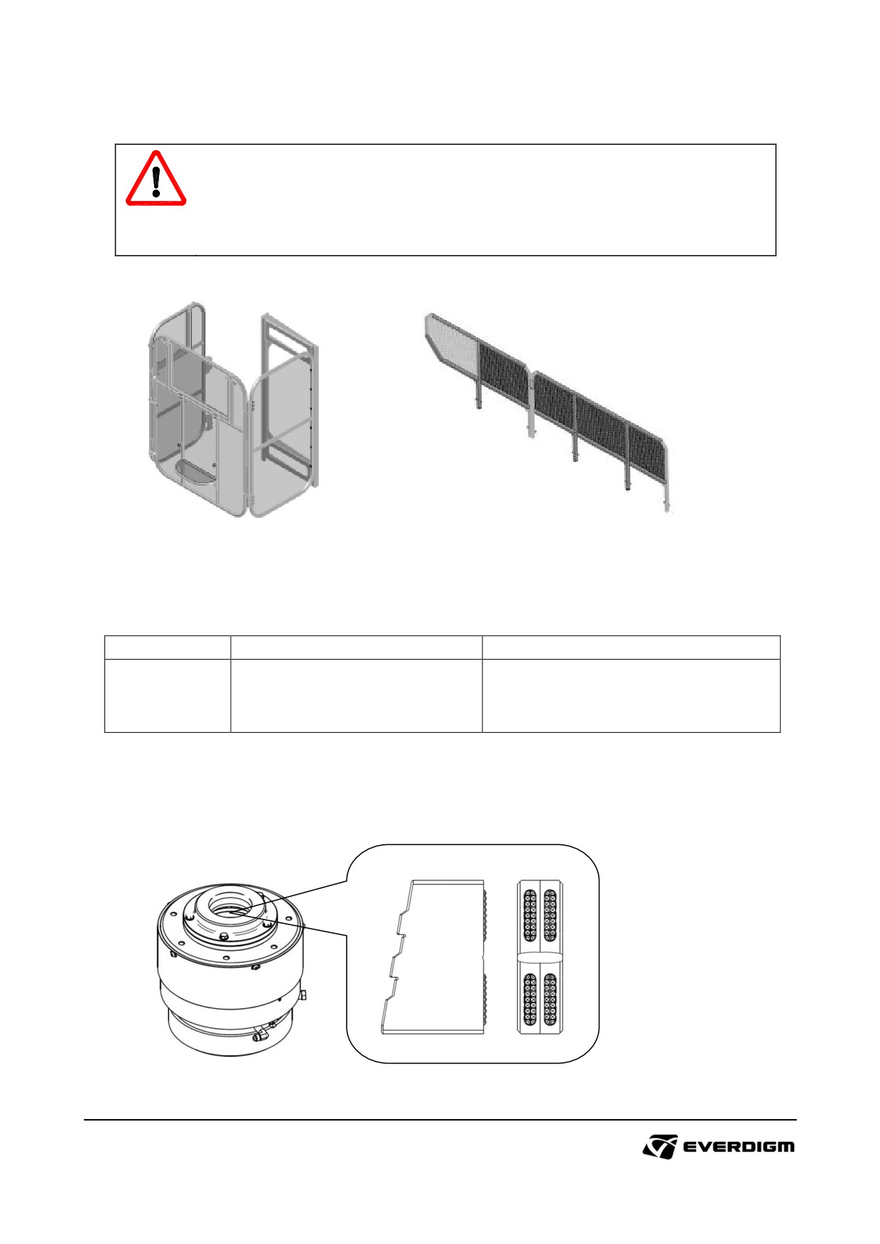
Spin cage or safety guard locking condition check
DANGER!
It is very dangerous if someone try to touch rotating parts while it is operating.
Do not allow to enter anybody on the machine during operation.
Close and lock safety devices completely before operation.
Figure: Spin cage (Option)
Figure: Side guard (Option)
Table: Safety guard check
Check point
Parts
Instruction
Check loosening of bolts and parts.
Spin cage
Tighten all loosen parts.
-
Close and lock the cage and guard
Side guard
before operation.
Wear of jaw tip check
Check wear condition of jaw tip inside of chuck before using it. Tips worn out, replace jaw with new
one.
Figure: Jaw tip inside of chuck
89
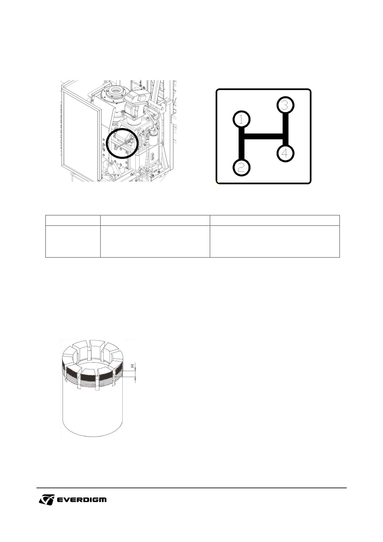
Rotary head transmission gear lever check
Figure: Transmission lever
Figure: Speed mode by transmission
Check point
Parts
Instruction
Change speed mode by gear and
check the rotation speed rpm.
-
Transmission gear
Check abnormal noise or sound
from transmission.
Diamond core bit condition check
Check wear condition of tip on the bit before using it. Tips or bit are damaged or worn out badly,
replace it with new one.
Figure: Diamond core bit wear check
90
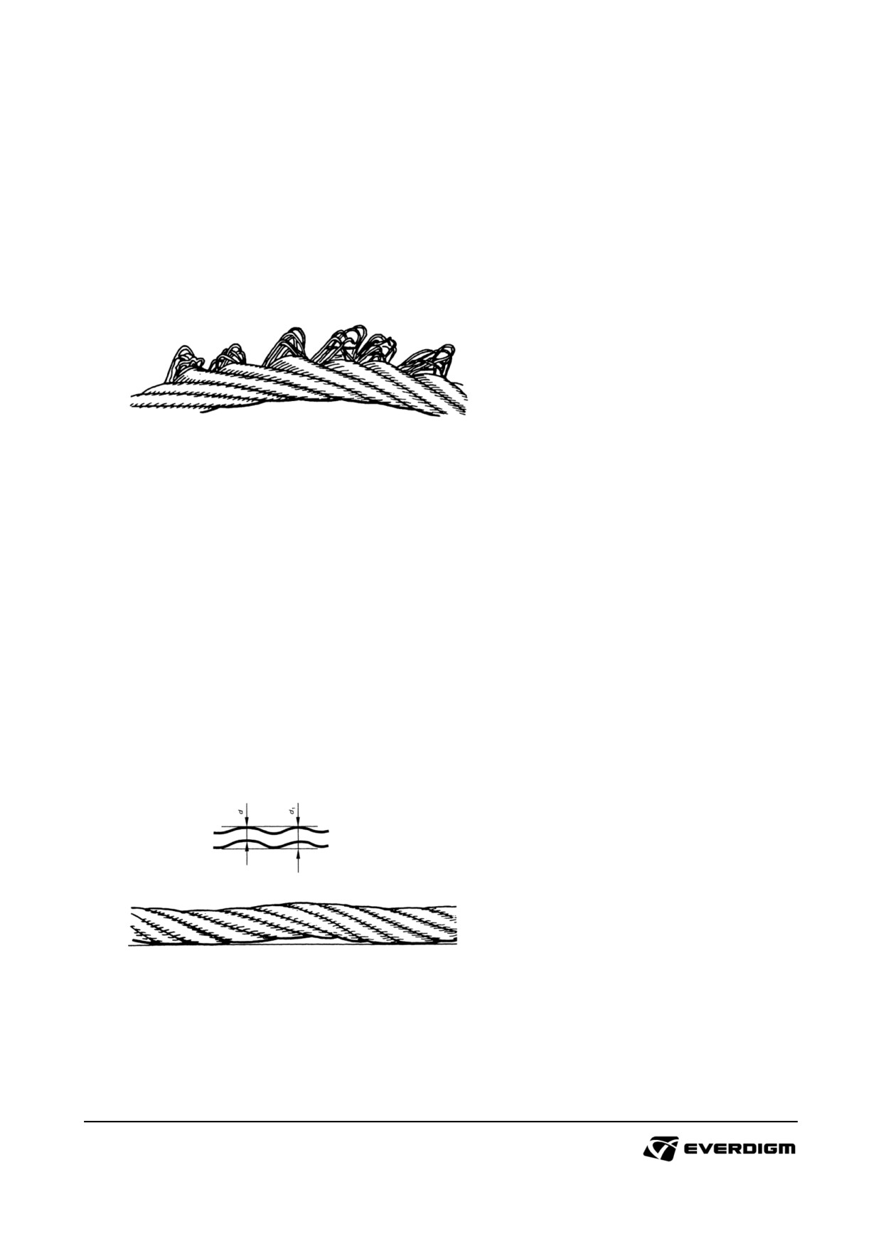
Wear or damages of steel rope
Check steel rope condition, and replace it if it is damaged as shown following examples.
Wire displacement
Individual wires or wire groups stick out like hairpins on the side facing away from the drum. Wire
displacement is caused by spasmodic loads.
Ropes with wire displacement must be scrapped.
Figure: Example of wire displacement
Waviness
Waviness is a deformation that gives the rope's longitudinal axis a helical curve. Even though wave
formation does not necessarily cause weakening of the rope, such a deformation can cause a pulsing
movement.
After a long time of operation, this can increase surface wear and wire breaks. In the event of
waviness, the rope should be scrapped if
d 1
> 4d/3
d = Rope's nominal diameter
d 1
= Diameter of the circle that would be formed if the rope were not deformed. Check over a length
not exceeding 25d.
Figure: Waviness
91
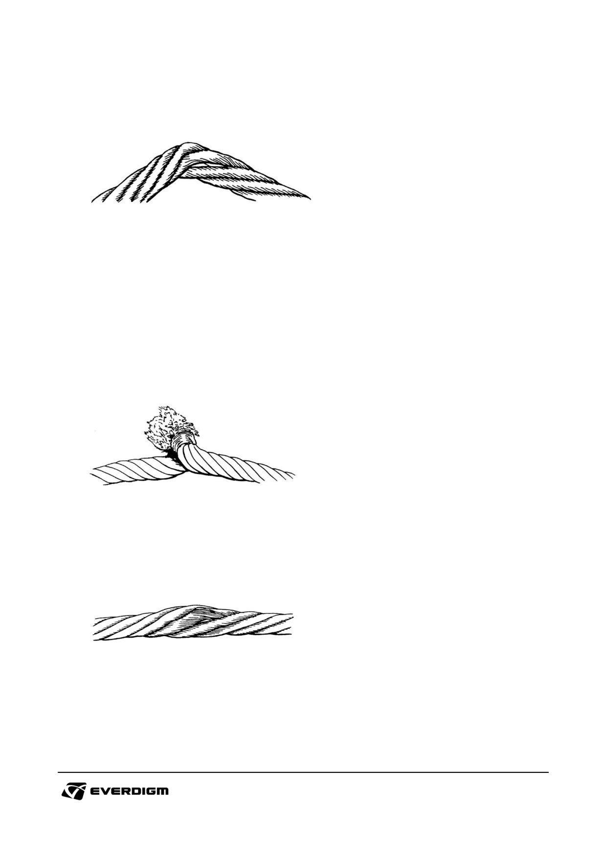
Cracks
Cracks are deformations through outer, violent influences. Ropes with cracks must be scrapped.
Figure: Cracks
Kinks
A kink is a deformation caused by the rope forming an eye that is contracted with out the rope being
able to rotate around its own axle.
Strand pitch is altered, which leads a great deal of surface wear and, in severe cases, very low static
strength.
Ropes with kinks must be scrapped.
Figure: Kinks
Flattening
Flattening is deformation caused by mechanical damage. Ropes with severe flattening must be
scrapped.
Figure: Flattening
92
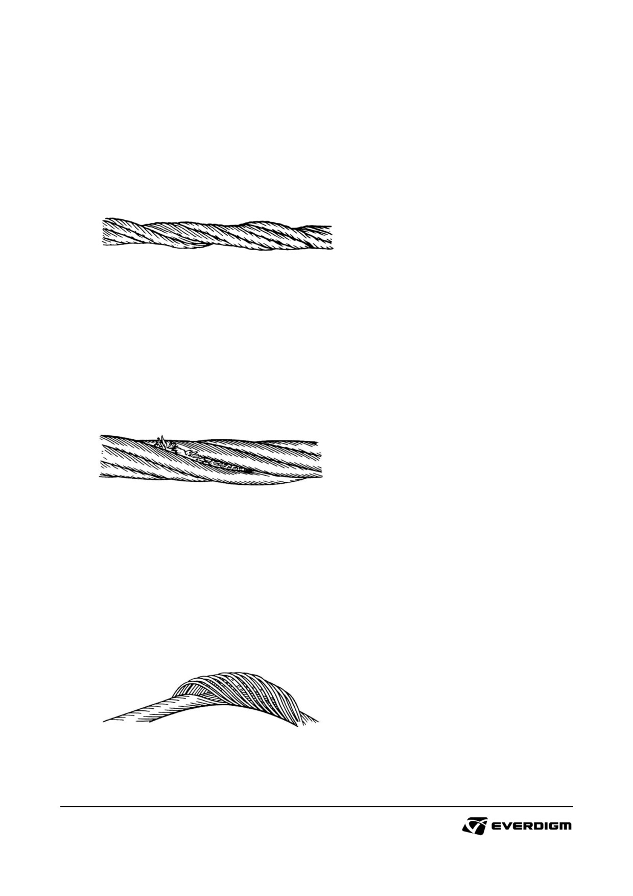
Local rope diameter decrease
Local decrease in rope diameter is often connected to core break.
The area near the end attachments must be inspected especially carefully as it can be difficult to
detect rope diameter decrease at these spots.
Ropes with severe rope diameter decrease must be scrapped.
Figure: Local rope diameter decrease
Local rope diameter increase
This means repeated thickening of the rope over a long stretch. At the thicker spots, the core pushes
out of the rope and causes unevenness of the outer strands.
Ropes with severe rope diameter increase must be scrapped.
Figure: Local rope diameter increase
Basket formation
Basket formation occurs on ropes with steel reinforcement or steel core when the outer strand layer
becomes longer than the inner strand layer.
Basket formation can also be caused by shock loads on slack ropes. Ropes with basket formation
must be scrapped.
Figure: Basket formation
93
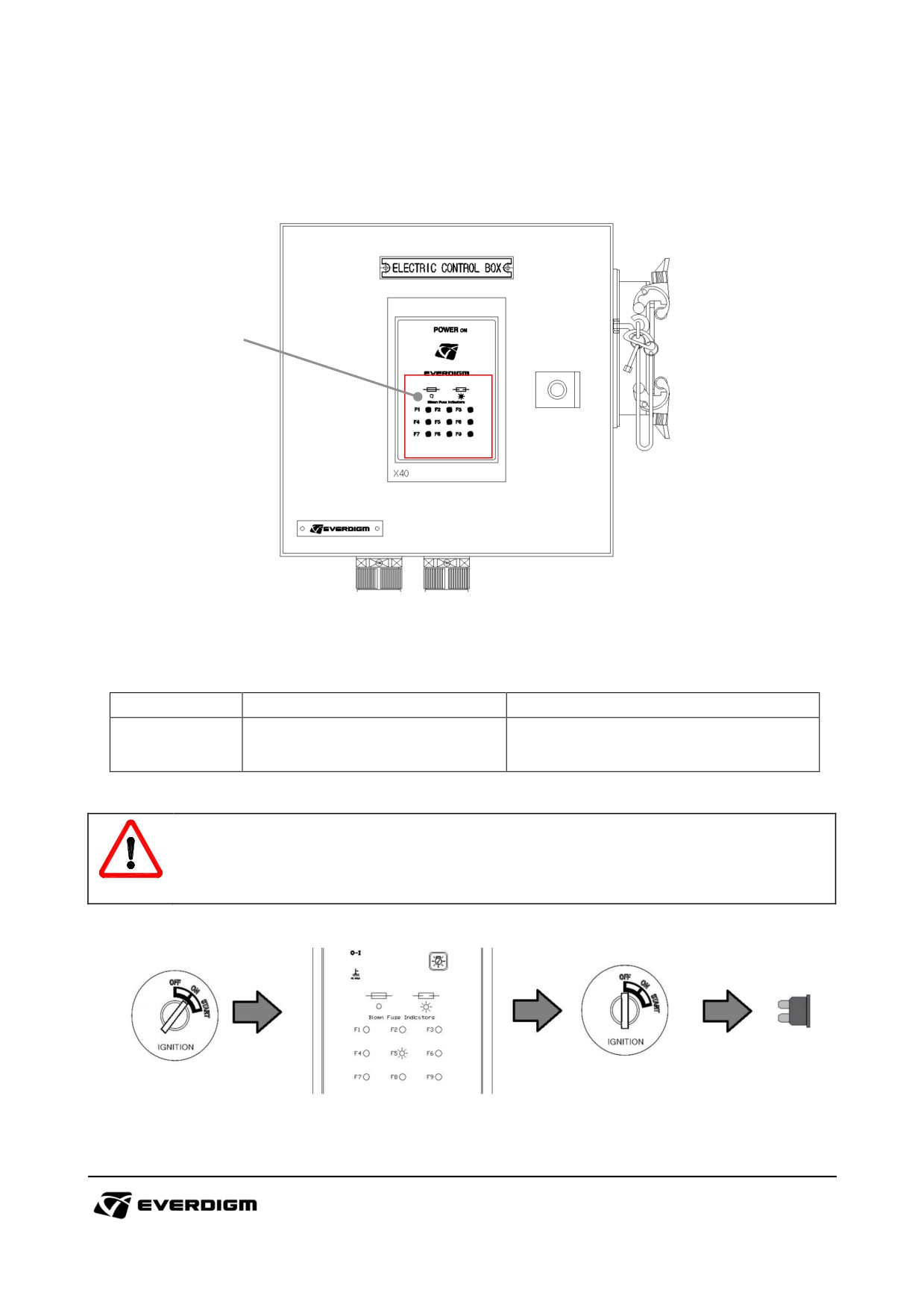
Main control panel check
Open bonnet and check if a fuse is blown. If fuse is disconnected, indicator will be lighted.
1
Figure: Main control panel front cover
Table: Main control panel front cover
Check point
Parts
Instruction
When light is "ON", the fuse is
1
Fuse lamp
disconnected.
IMPORTANT!
When replace a fuse, use the same capacity fuse unless it will burn electric system or devices.
Before changing fuse, turn off starter key switch in the cabin.
Figure: Fuse check and change procedure
94
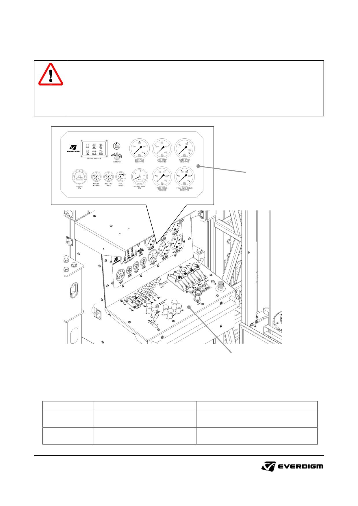
4.5.2 Main controllers
WARNING!
Only trained operator can be allowed to operate the machine.
When training for operation is required, contact official Everdigm distributor for assistance.
Mast is very long structure and it may hit other objects during operation. Always observe
movement of mast and rotary head while it is operating
1
2
Figure: Main controllers
Table: Main controllers
Check point
Parts
Instruction
Gauges (temperatures, pressures ,
1
Gauge panel
engine), Ignition and cigar jack.
Drilling control, pressure adjusters,
2
Control panel
switches.
95
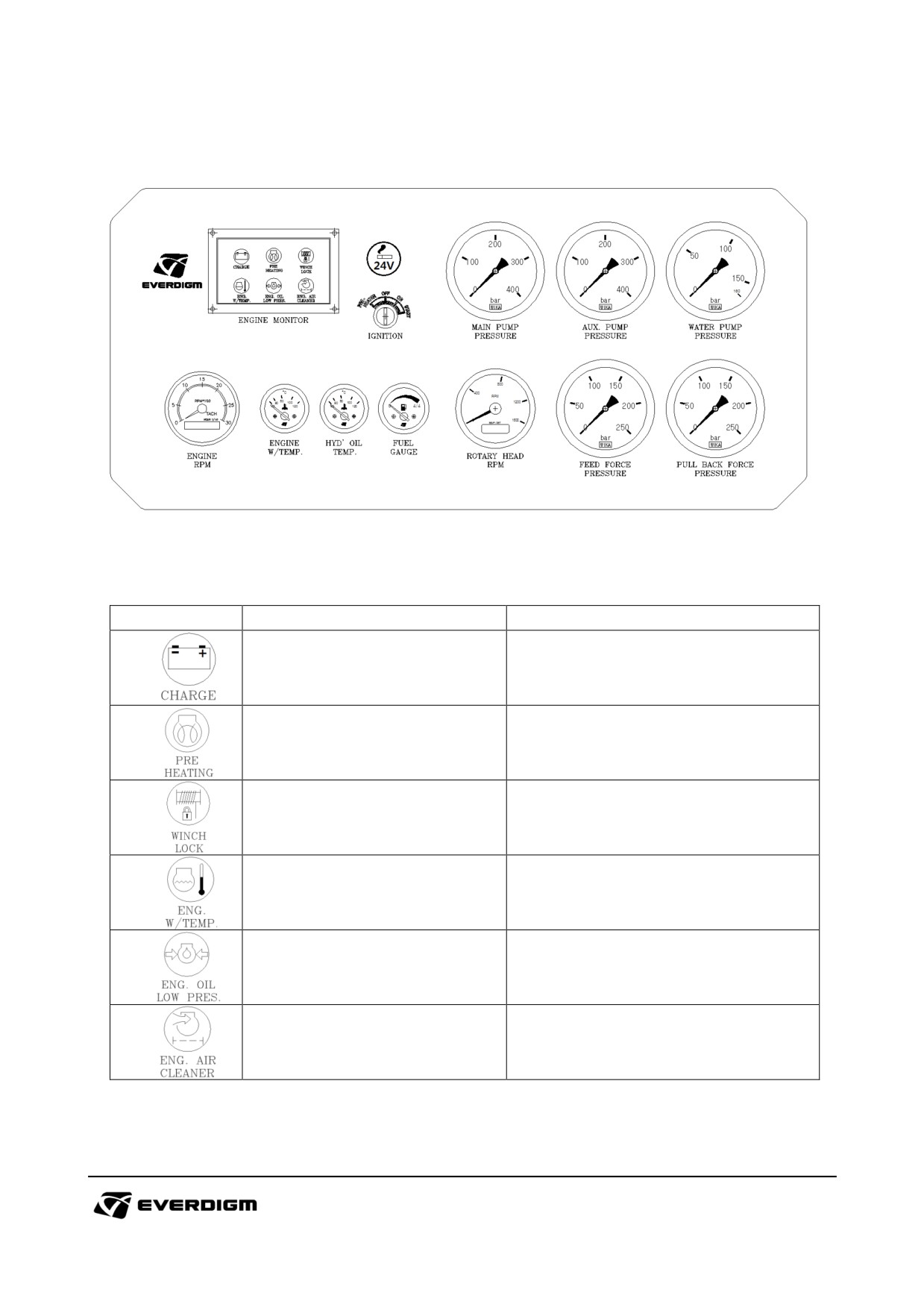
4.5.2.1 Gauge panel
Figure: Gauge panel
Table: Engine monitor
Symbol
Description
Instruction
Low voltage is detected when it
Low electricity
light. Check battery condition.
Engine preheating
Engine preheating is activated.
Winch lock indicator
Winch lock is activated
High coolant temperature is
Engine coolant temperature
detected when it light. Check the
warning
coolant temperature.
Low engine oil pressure is detected
Low engine oil pressure
when it light. Check engine oil level
warning
and condition.
Engine air filter blockage is
Air filter blockage warning
detected. Check air filter, and clean
or replace filter.
96
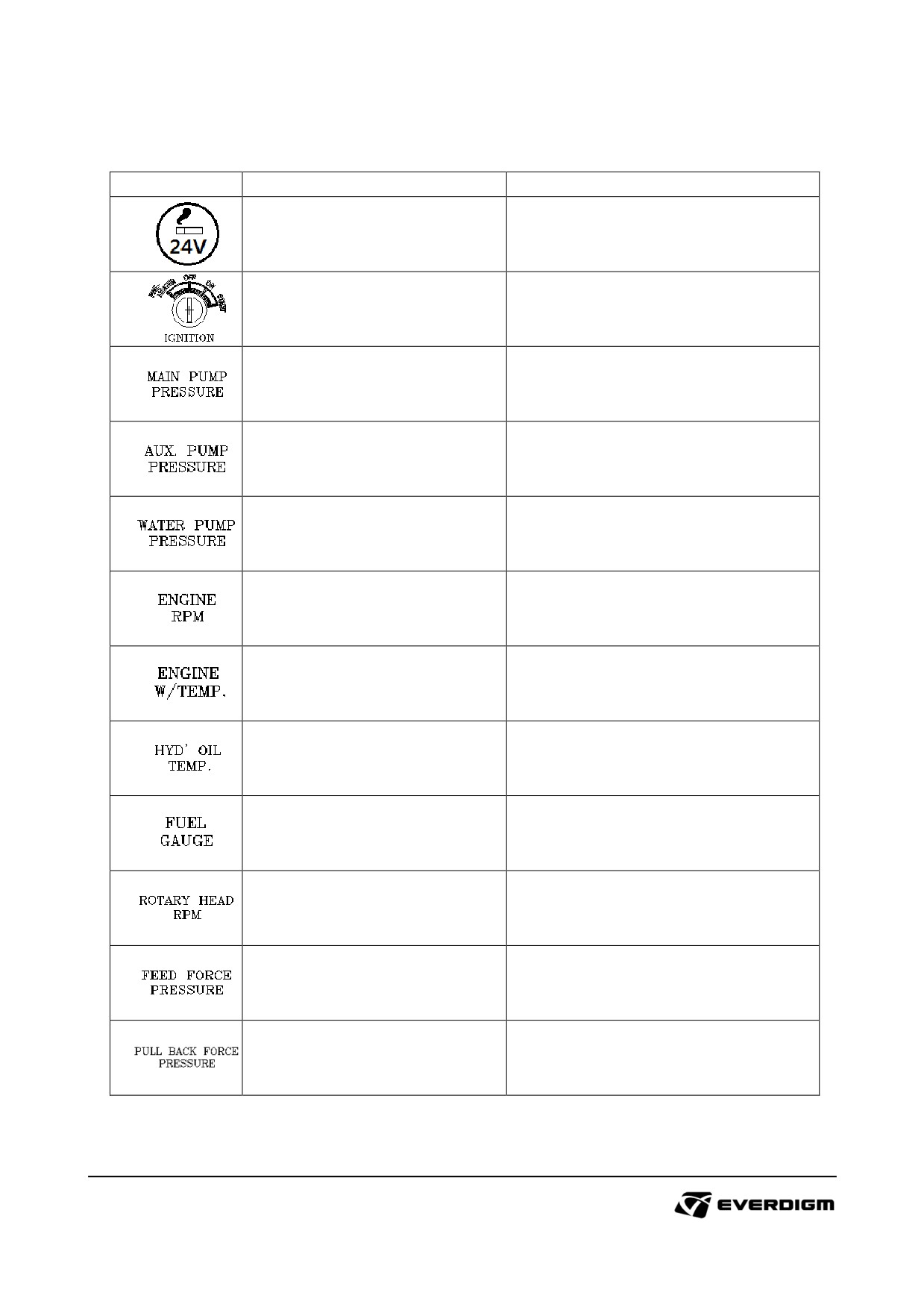
Table: Gauge panel
Symbol
Description
Instruction
Cigar jack
24V D/C output port
Starting or stop engine with master
Engine starter
key.
It shows the current main pump (P1)
Main pump pressure gauge
pressure.
It shows the current auxiliary pump
Auxiliary pump pressure gauge
(P2) pressure.
It
shows current water pump
Water pump pressure gauge
pressure.
It shows current engine rpm with
Engine RPM tachometer
engine hour.
Engine coolant temperature
It shows current engine coolant
gauge
temperature.
It shows the current hydraulic oil
Hydraulic oil temperature gauge
temperature.
It shows remained fuel level on the
Fuel level gauge
fuel tank
It shows the current rotary head
Rotary head rpm gauge
rotation speed.
Feed force pressure gauge
It shows current feed pressure.
Pull back force pressure gauge
It shows the pull back pressure.
97
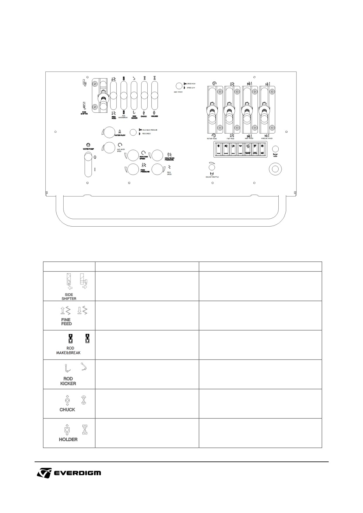
4.5.2.2 Control panel
Figure: Main control panel
Table: Main control panel
Symbol
Description
Instruction
Lever for moving rotary head to
Rotary head side shift lever
each sides.
Lever for fine feed forward and
Fine feed operation lever
backward movement.
Lever
for
connecting
and
Rod make and break lever
disconnecting pipe operation.
Rod kicker lever
Lever for rod kicker operation
Lever for opening and closing chuck
Chuck operation lever
to hold pipe
Lever for opening and closing foot
Foot clamp operation lever
clamp to hold pipe
98
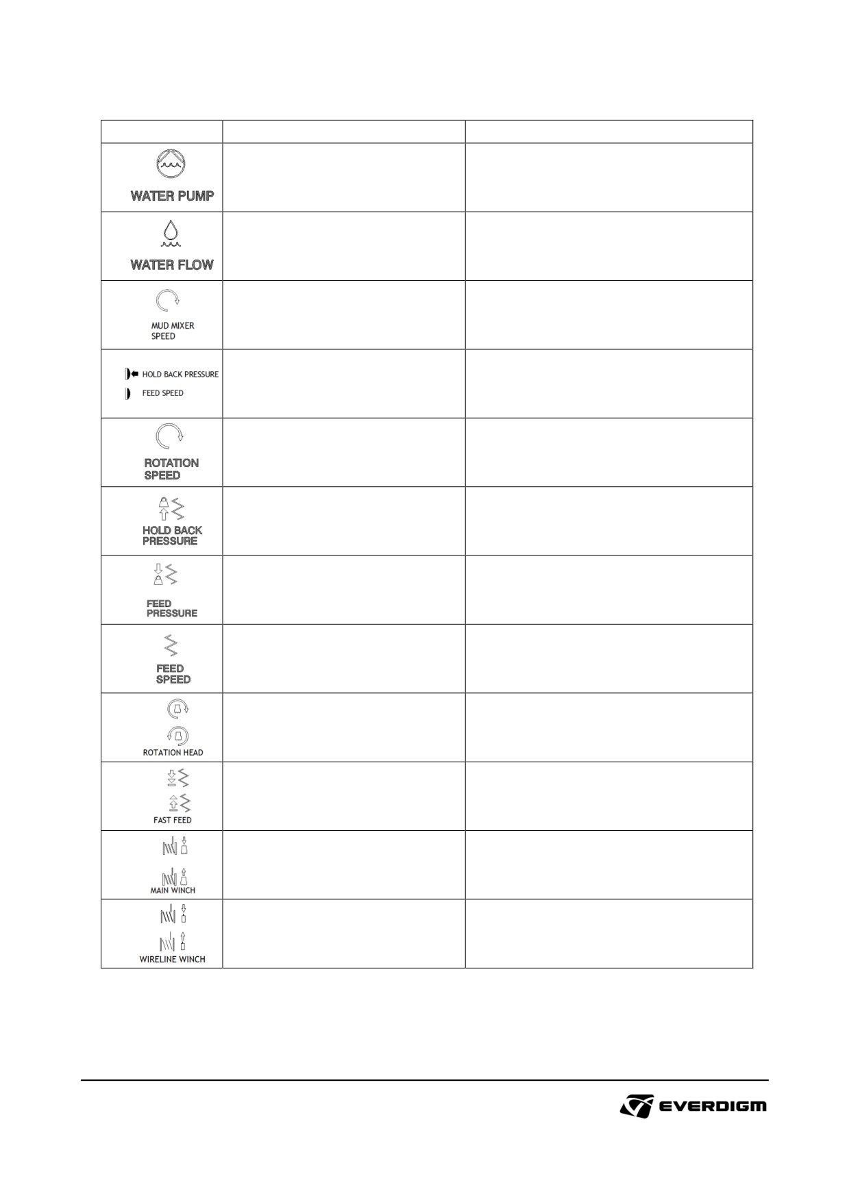
Symbol
Description
Instruction
Water pump operation.
Water pump operating lever
O : OFF
I : ON
Water flow knob
Water flow adjusting valve
Mud mixer rotating speed knob
Mud mixer speed adjusting valve
Selects between fine feed speed
Hold back pressure / Fine feed
valve and hold back pressure valve
speed valve selection s
to control penetration rate and
balance rod weight during drilling.
Rotary head rotation
speed
Rotation speed knob
adjusting valve
Hold back pressure knob
Hold back pressure adjusting valve
Feed pressure knob
Feed pressure adjusting valve.
Feed speed knob
Feed speed adjusting valve
Rotary head operation lever
Rotary head operation lever
(Clockwise or counterclockwise)
Rotary head feed movement
Rotary head feed operation lever
operation. (Forward or Backward)
Main winch operation lever
Winding or unwinding main wire
Wireline winch operation lever
Winding or unwinding wireline wire.
99