EVERDIGM Core Drill Rig ECR12 & ECR18. Operation and Maintenance Manual (2016.02.27) - page 4
6.2.3 Trouble shooting for coolant preheater
In the event of a mal function, fuses and electrical connections should be checked for proper condition
and security.
If this action does not correct the failure, consult with your authorized Webasto dealer.
After the heater has been shut down due to a fault lock-out, coded flashing signal is emitted through
the operation indicator during the after-run cycle of the heater. These coded flashing signals are
designed to assist the authorized Webasto dealer in isolating the fault.
Heater turns itself off automatically (=fault lock-out)
Cause
Remedy
Combustion was not established during
√ Switch heater off and then on again.
start-up and start-up repetition.
√ If the heater fails to re-start, consult with authorized
Frame goes out during operation.
Webasto dealer nearby you.
Voltage drop for more than 20 seconds
√ Check fuses, electrical connections and battery
Heater overheats due to lack/loss of coolant
√ Fill up coolant according to instruction
Fault code display
The following error code will be shown in the digital timer display by self diagnostic system.
F 01
: No start-up (after 2 start-up attempts)
F02
: Fame extinguished
F03
: Undervoltage or overvoltage
F04
: Premature flame detection
F05
: Fame detector interruption or flame detector short-circuit
F06
: Temperature sensor interruption or temperature sensor short-circuit
F07
: Metering pump interruption or metering pump short-circuit
F08
: Fan motor interruption or fan motor short-circuit or incorrect fan motor speed
F09
: Pencil-type glow plug interruption or pencil-type glow plug short-circuit
F10
: Overheating
F11
: Circulating pump interruption or circulation pump short circuit
150
6.3 Operator cabin
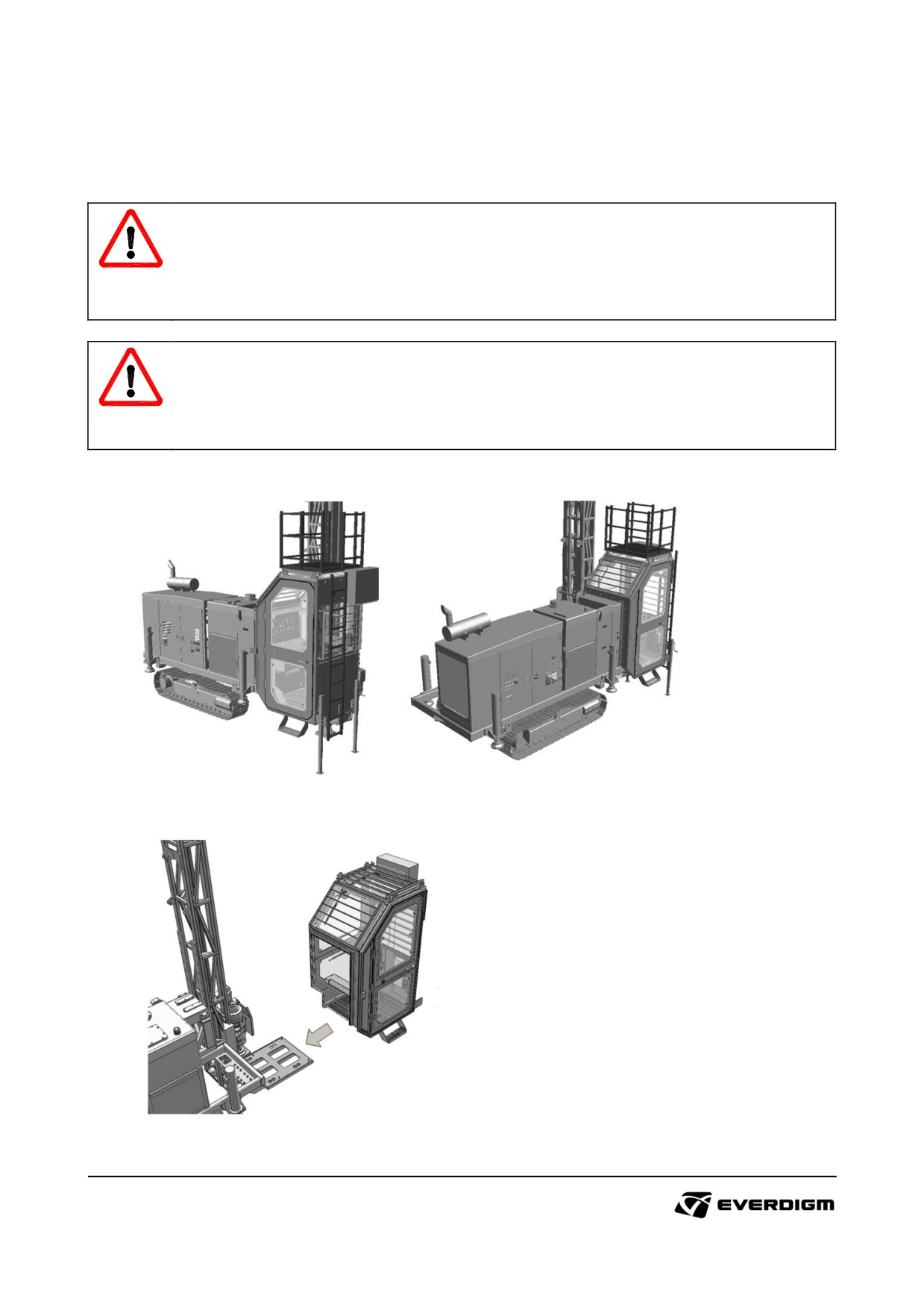
Operator cabin provides clean and safe operation by isolating operating area. Cabin can be supplied
as option kit.
DANGER!
Installing cabin on the machine will break weight balance of machine. Do not travel the
machine when cabin is installed on.
Before installing cabin, extend outriggers for supporting machine correctly.
WARNING!
Cabin can not completely isolate the operator with atmosphere air, and toxic air and dust may
come inside of cabin.
6.2.1 External figure and dimensions
Figure : External figure after installation
Figure : Cabin installation
151
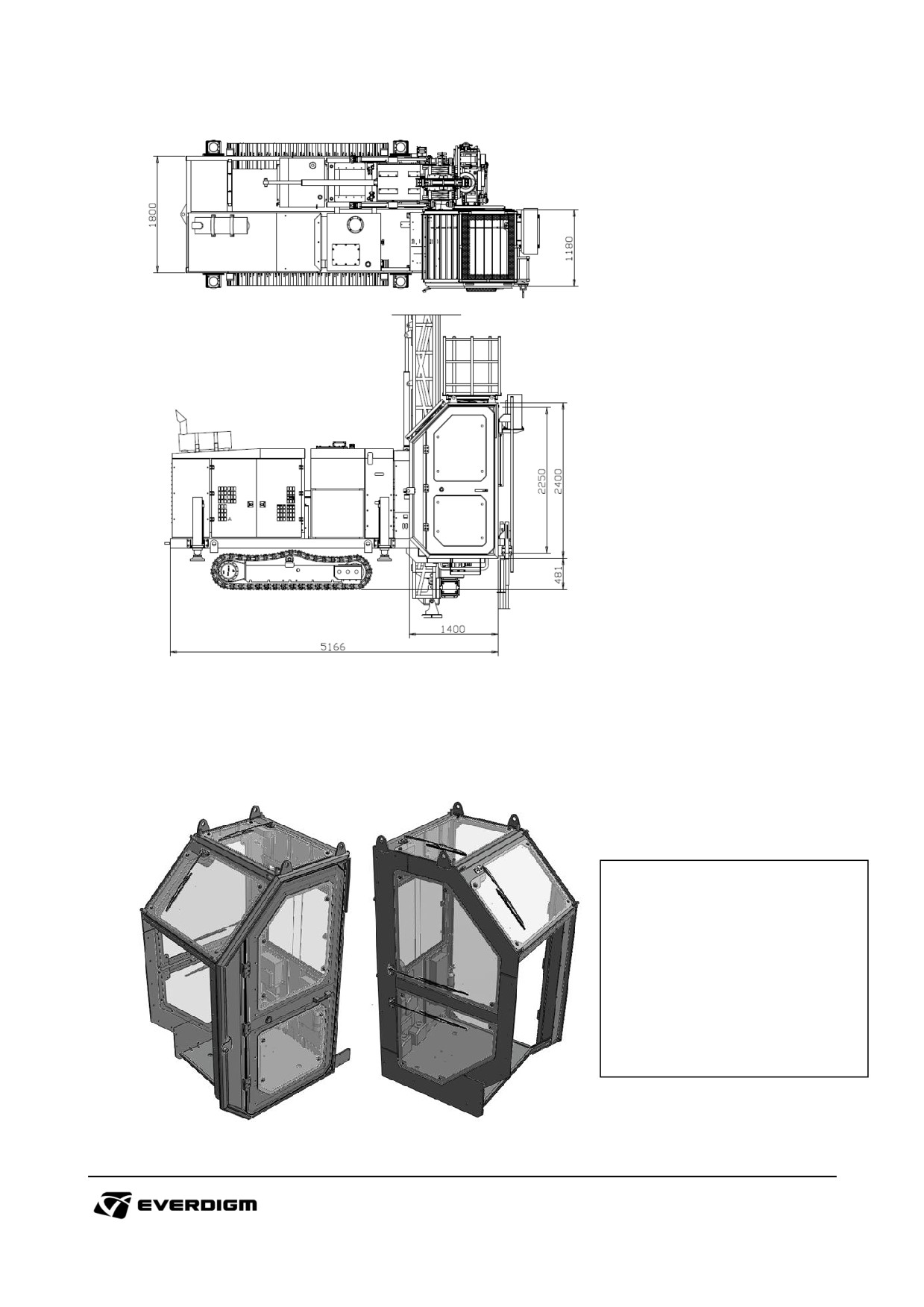
Figure : Dimensions
6.2.2 Features and benefit
Window and wipers
Two Large Tempered Glasses (5mm)
and Wiper at Top
Two Large Tempered Glasses and
Wiper at Rotary Head Side
Two Large Tempered Glasses at Door
One Sliding Chassis (with Tempered
Glassed) at Rear
Figure : Window and wipers
152
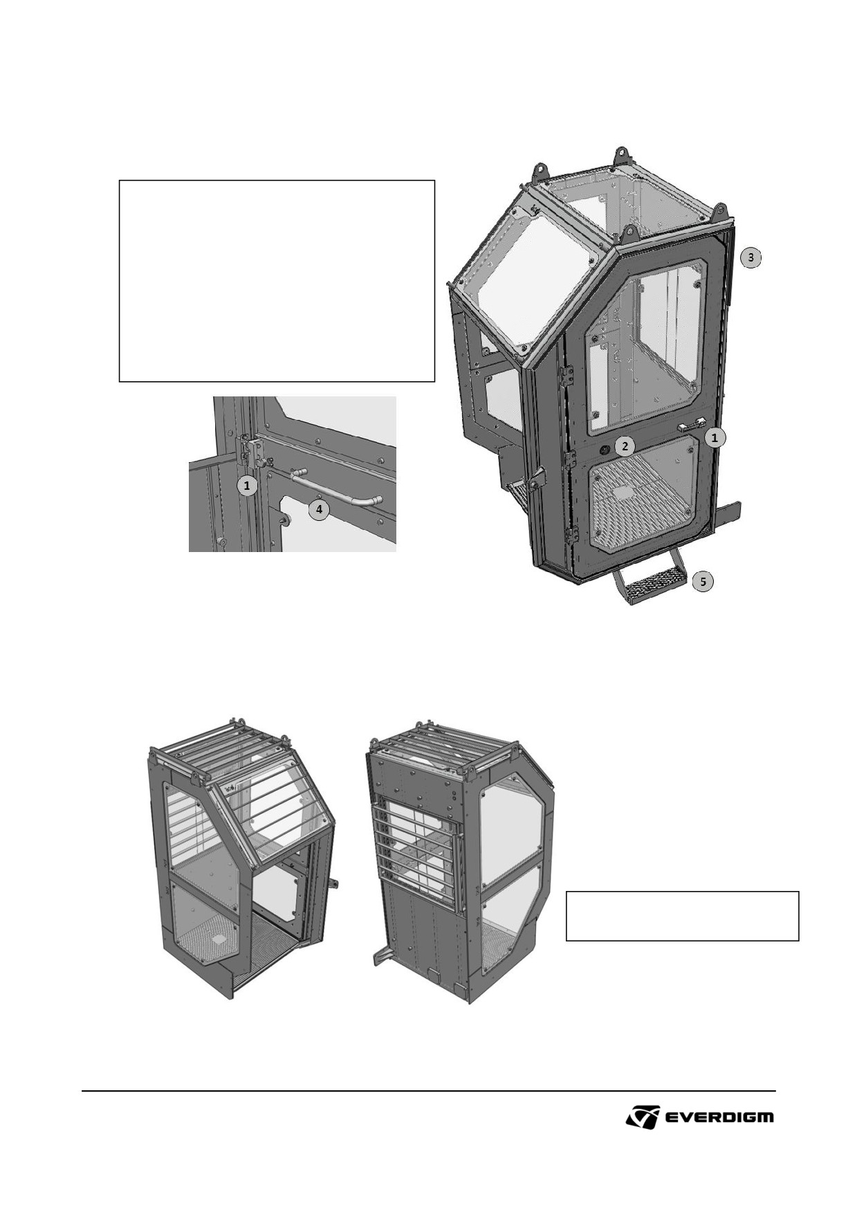
Window and wipers
① Strong and Durable Door Handle and Catch
② Wide Door Opening (170°) and Door Lock-
Release Catch
③ Rain eaves to prevent leakage
④ Door Grab Bar
⑤ Step plate for easy Access
Figure : Window and wipers
Protection guard
Strong and Rugged Guard to guard
glasses from damage
Figure : Protection guard
153
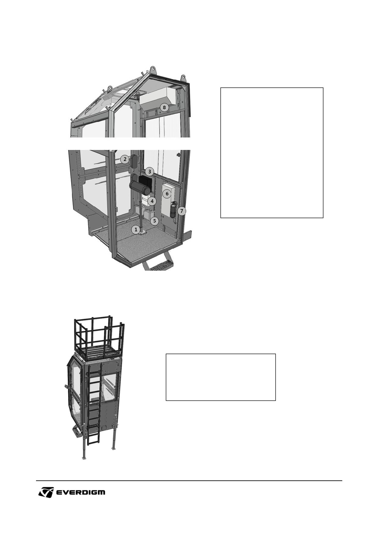
Interior
① Standing Seat (Adjustable)
② Wiper Motor 4ea
③ Wiper Motor Control Box
④ Inverter (DC24 to DC12)
⑤ Wiper Washer Bottle
⑥ Inverter (DC to AC)
⑦ Extinguisher
⑧ Air conditioner ⑧
Figure : Interior
Ladder
Ladder and Guardrail Structure to
maintenance the mast, rotary head
at High position
Support Jack to hold the cabin strong
Figure : Ladder
154
7. Torque table
Bolt
Strength
8.8
10.9
12.9
Normal Fine
Spec
N.m
kgf.m
N.m
kgf.m
N.m
kgf.m
●
M4 x 0.7
2.8
0.3
4.1
0.4
4.8
0.5
●
M5 x 0.8
5.5
0.6
8.1
0.8
9.5
1.0
●
M6 x 1.0
9.5
1.0
14
1.4
16.5
1.7
●
M8 x 1.0
24.5
2.5
36
3.7
43
4.4
●
M8 x 1.25
23
2.3
34
3.5
40
4.1
○
M10 x 1.0
52
5.3
76
7.8
89
9.1
●
M10 x 1.25
49
5.0
72
7.3
84
8.6
●
M10 x 1.5
46
4.7
68
6.9
79
8.1
●
M12 x 1.25
87
8.9
125
12.5
150
15
○
M12 x 1.5
83
8.5
122
12.5
145
15
●
M12 x 1.75
79
8.1
117
12
135
14
●
M14 x 1.5
135
14
200
20
235
24
●
M14 x 2.0
125
13
185
19
215
22
●
M16 x 1.5
205
21
300
30
360
37
●
M16 x 2.0
195
20
280
28
330
34
●
M18 x 1.5
310
32
440
45
520
53
○
M18 x 2.0
290
30
420
43
490
50
●
M18 x 2.5
280
29
390
40
460
47
●
M20 x 1.5
430
44
620
63
720
73
●
M20 x 2.5
390
40
560
57
650
66
●
M22 x 1.5
580
59
820
83
960
98
●
M22 x 2.5
530
54
750
76
880
90
○
M24 x 1.5
760
77
1,090
110
1,270
130
●
M24 x 2.0
730
74
1,040
105
1,220
125
●
M24 x 3.0
670
68
960
98
1,120
115
○
M27 x 1.5
1,110
115
1,580
160
1,850
190
●
M27 x 2.0
1,070
110
1,500
150
1,800
185
●
M27 x 3.0
1,000
100
1,400
140
1,650
170
○
M30 x 1.5
1,540
155
2,190
225
2,560
260
●
M30 x 2.0
1,490
150
2,120
215
2,480
255
●
M30 x 3.5
1,350
140
1,900
195
2,250
230
○
M33 x 1.5
2,050
210
2,920
300
3,420
350
●
M33 x 2.0
2,000
205
2,800
285
3,300
335
●
M33 x 3.5
1,850
190
2,600
265
3,000
305
○
M36 x 1.5
2,680
275
3,820
390
4,470
455
●
M36 x 3.0
2,500
255
3,500
355
4,100
420
●
M36 x 4.0
2,350
240
3,300
335
3,900
400
○
M39 x 1.5
3,430
350
4,890
500
5,720
585
●
M39 x 3.0
3,200
325
4,600
470
5,300
540
●
M39 x 4.0
3,000
305
4,300
440
5,100
520
155
8. Trouble shooting
8.1. Engine
Cause
Main cause
Remedy
Lack of coolant
√ Refill or replace coolant
Blocked radiator fins
√ Clean radiator
Leak from reservoir tank
√ Tighten cap
cap
Engine coolant
√ Check the inner side of radiator and clean it
temperature is too high.
Blockage of coolant line
√ Check coolant piping and clean it
Malfunction of sensor or
√ Repair or replace
temperature gauge
Lack of fan motor
√ Check blow condition from fan and hydraulic
efficiency, or failure
motor
Emergency stop system is
√ Check and disable emergency condition
activated.
Master switch is off
√ Turn on master switch
Engine can not be
started.
Disconnected electric line
√ Check electric connections
(Engine is not cranked)
Empty batteries
√ Check and recharge batteries
Ignition switch failure
√ Repair or replace
Lack of fuel
√ Refill fuel
Mixed air into fuel
√ Exhaust air on fuel line
Engine can not be
Fuel injection pump or
√ Contact official engine service dealer. Change
started.
nozzle failure
failed parts
(Engine is cranked)
Blockage of fuel line or
√ Replace fuel filters and cleaning fuel line
filters
Fuel leakage from piping
√ Check and repair the fuel line
and hoses
Lack of alternator efficiency
√ Check the tension of alternator
Battery charging lamp is
"ON"
Alternator failure
√ Check and change alternator
Lack of engine oil
√ Check the pressure of engine oil and refill it
Sudden engine stop
High coolant temperature
√ Check radiator and coolant condition
during operation
High compressor oil
√ Check compressor oil condition
temperature
√ Check oil fan condition
156
Cause
Main cause
Remedy
Engine RPM can not be Cable connection failure
√ Check cable (wire) connection between rpm
adjusted
(Cummins Engine)
adjuster and engine
√ Turbo charger is polluted. Clean turbo
charger.
Dark color
√ Air filter is blocked. Clean or replace air filters.
Abnormal exhaust gas
√ Engine oil can be burned. Check remained
from muffler
engine oil level, and repair piston rings.
White color
√ Air may be mixed with fuel. Check and
exhaust air in fuel.
8.2. Traveling
Cause
Main cause
Remedy
Excessive track tension
√ Adjust tension
√ Check pilot line pressure. Clean pilot line and
Pilot line blockage
replace filter
Failed track motor
√ Repair or replace
Machine won’t travel.
Control lever or valve
Traveling is difficult.
√ Repair or replace
failure
Insufficient hydraulic
√ Adjust hydraulic pressure
pressure from relief valve
Main pump failure
√ Repair or replace
Break valve failure
√ Check spool and valve
Machine slips on a slop
with parking position
Too much load on the
√ Remove heavy object on the machine
machine
Loosen track tension
√ Adjust tension
Worn out idler, roller, or
Track shoe gets out of
√ Replace parts
sprocket
it's place
Worn out or broken track
√ Replace track shoe assembly
shoe
157
8.3. Rotary head
Cause
Main cause
Remedy
Too much gear oil in
√ Check and adjust oil level
transmission
Too much heat is
√ Check oil circulation condition through silicon
generated from
No oil circulation
hose. Change oil pump.
transmission
Blockage of filters
√ Check and change oil and suction filters.
Internal gear damage
√ Check gear condition
Abnormal sound from
Wear of bush and bearing
√ Change bush and bearing
transmission
Abnormal contact of
√ Check if a components interrupt of other
components
components during rotation.
√ Check pipe size and jaw size if they are
Wrong sized jaw
matched correctly.
Chuck does not hold
√ Check jaw tip wear condition and change
Worn out jaw tip
pipe
jaws.
√ Check if chuck hold / opening condition and
Chuck hold lever
operate lever
Transmission shift lever
√ Check if gear shift lever is set correctly
Rotary head rotation
√ Adjust Rotary head rotation speed control
Low rotation speed setting
speed is too slow
knob
Low engine RPM
√ Adjust engine RPM
158
8.4. Oil cooler
Cause
Main cause
Remedy
Blocked oil cooler by dust
√ Clean oil cooler
Low cooling motor
√ Check hydraulic condition to motor
Hydraulic oil
efficiency
√ Repair or replace motor
temperature is too hot
Low hydraulic oil level
√ Fill hydraulic oil in tank
Temperature gauge or
√ Repair or replace
sensor failure
8.5. Hydraulic cylinders
Cause
Main cause
Remedy
Damaged seals
√ Replace internal seals
Hydraulic setting problem
√ Check hydraulic pressure and flow, and adjust
Hydraulic cylinder is not
Control lever or valve
operated or moves slow
√ Repair or replace
failure
Electric solenoid valve
√ Check electric signals
failure
√ Replace solenoid valve
159