Dynapac Asphalt paver wheeled F80W Hatz. WORKSHOP MANUAL (2019) - page 5
14
Belt conveyors and augers
14.7.1
Measuring the belt conveyor drive
switch S7
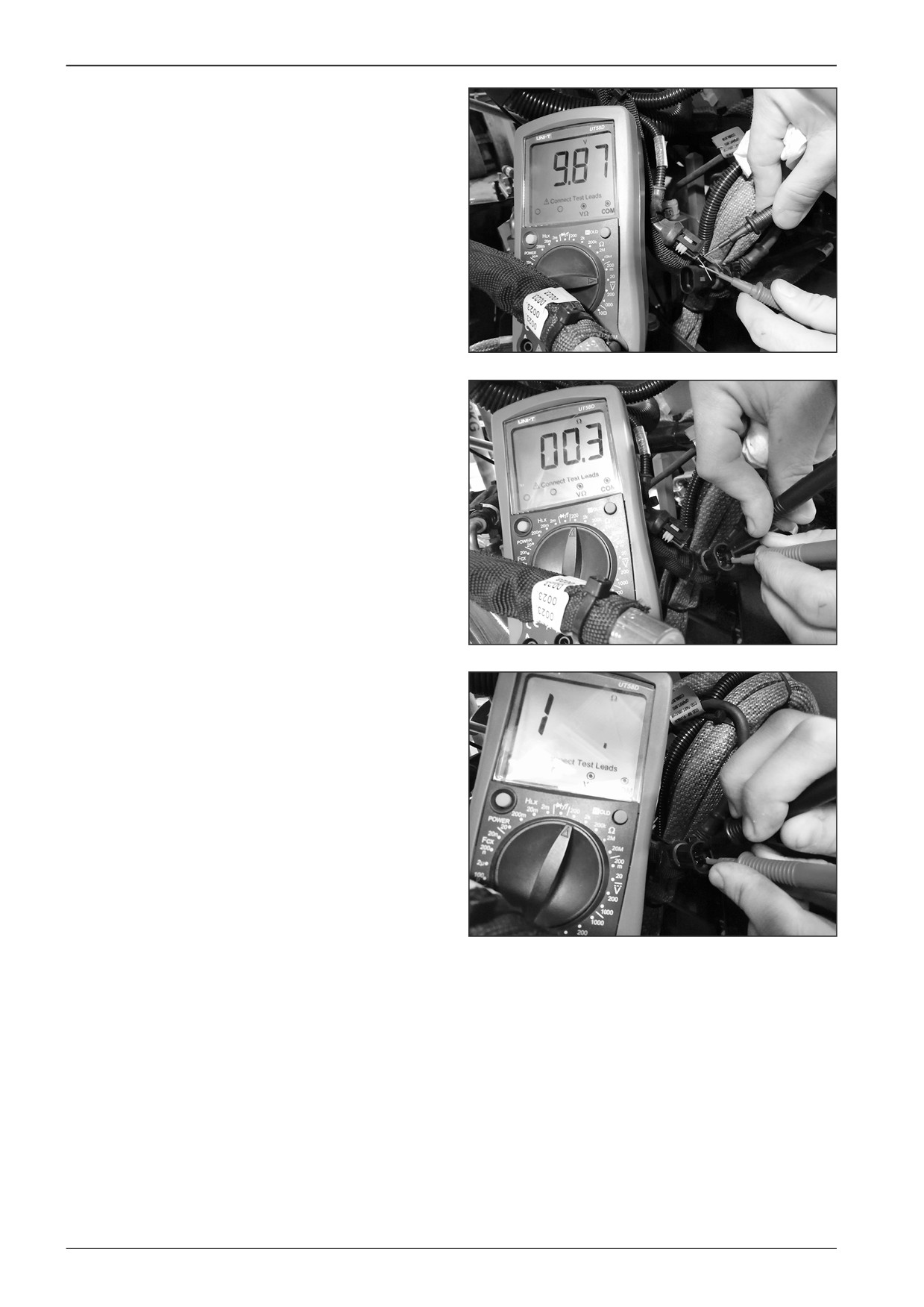
Voltage measurement
•
Disconnect the connector X43.
•
Turn the key in the ignition box to the “I“ position.
•
Measure the voltage of 9.9 V on the connector on the cable
harness side.
DD451039
Resistance measurement
•
Disconnect the connector X43.
The switch in the ON status (the material delivery is active).
•
Measure the resistance of approximately 0.3 Ω on the con-
nector on the switch side.
DD451040
The switch in the disconnected status (the material delivery is
interrupted).
•
Measure the opened circuit on the connector on the switch
side.
DD451041
170
F80W
WORKSHOP MANUAL
14.8
Dismounting the driving gear wheel of
augers
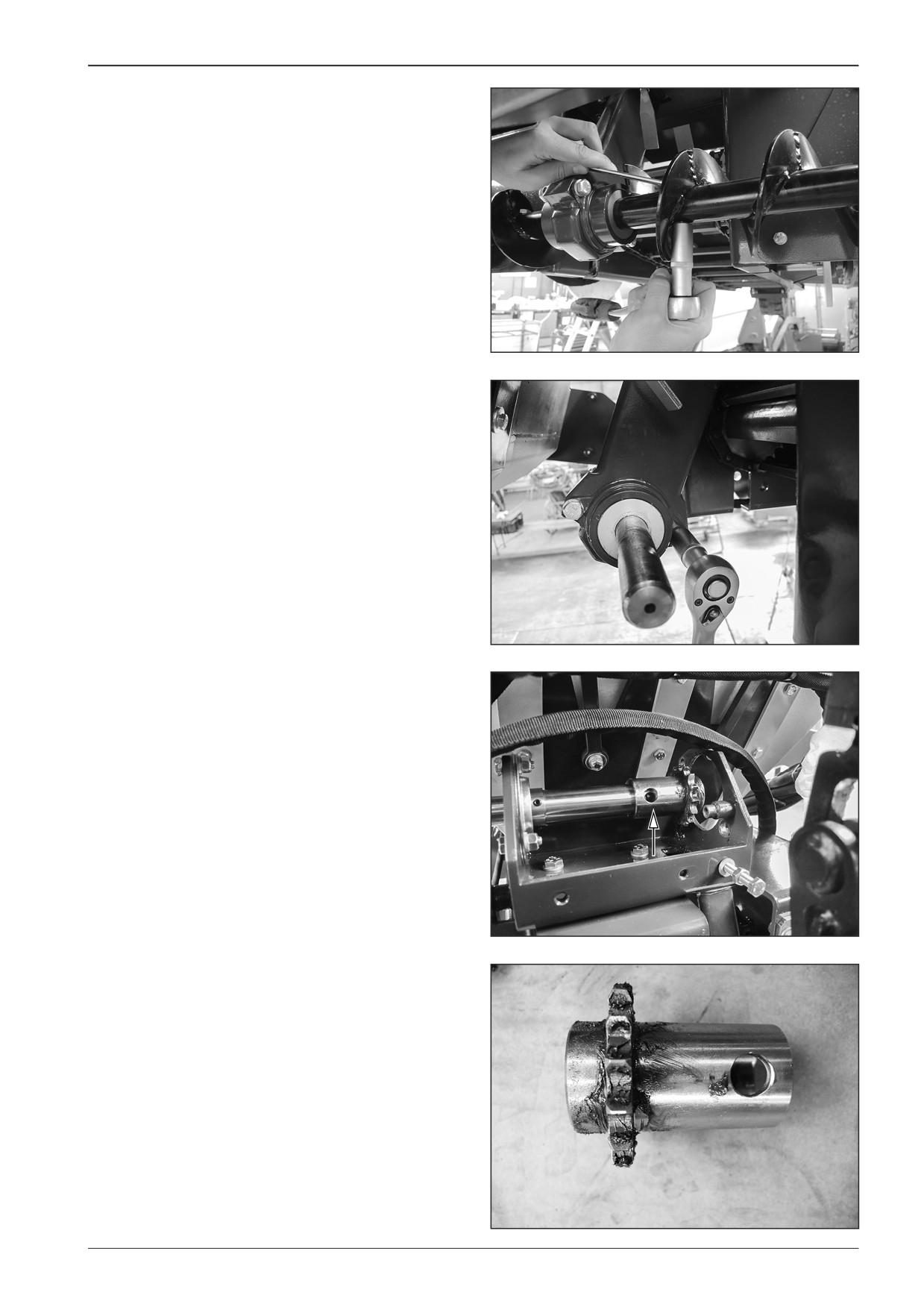
Dismount the driving gear wheel of augers from the machine
with the switched off battery disconnecter and with the closed
gas bottle valve.
Remove the augers.
Remove the lock screws.
D451549
Remove the screws on the right and left side (4x).
Remove the auger chain according to Chapter 14.6.
D451550
Remove the screw.
Dismount the driving gear wheel of augers.
D451572
D451573
F80W
171
14
Belt conveyors and augers
14.9
Replacement of consumables
14.9.1
Belt conveyor chain guide plate
Replace the belt conveyor chain guide plate on the machine
with the switched off battery disconnecter and with the closed
gas bottle valve.
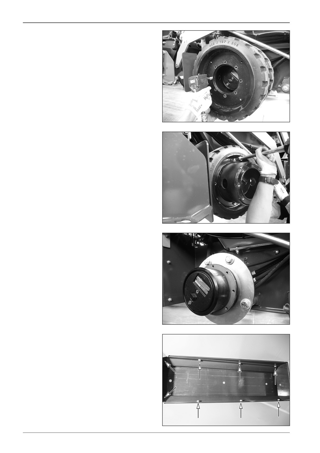
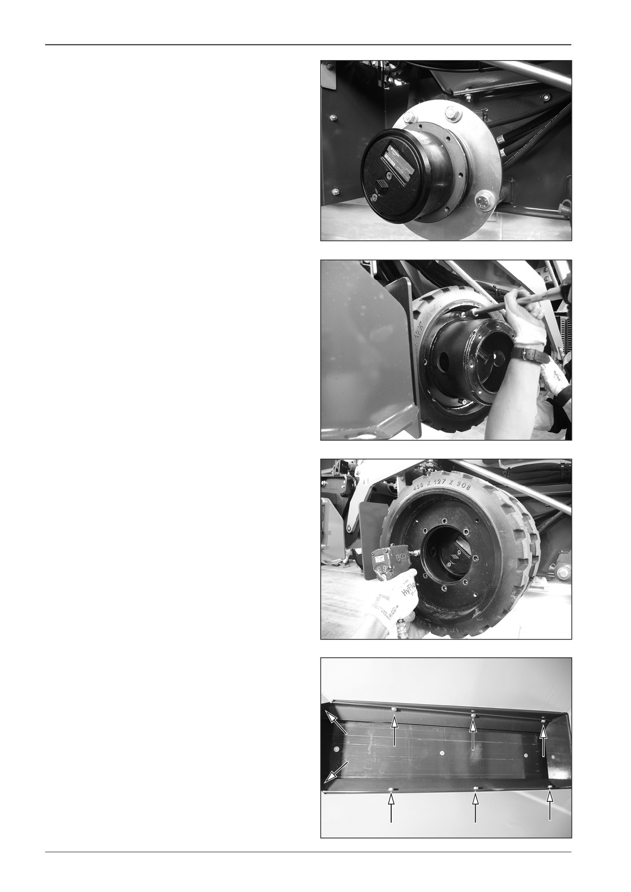
Remove the rear wheels on the left and right side of the ma-
chine.
Remove the belt conveyor drive chain according to Chapter
14.5.
Remove the belt conveyor chain according to Chapter 14.2.
D451517
D451518
D451519
Remove the cover plates.
•
Remove the screws (8x).
D451557
172
F80W
WORKSHOP MANUAL
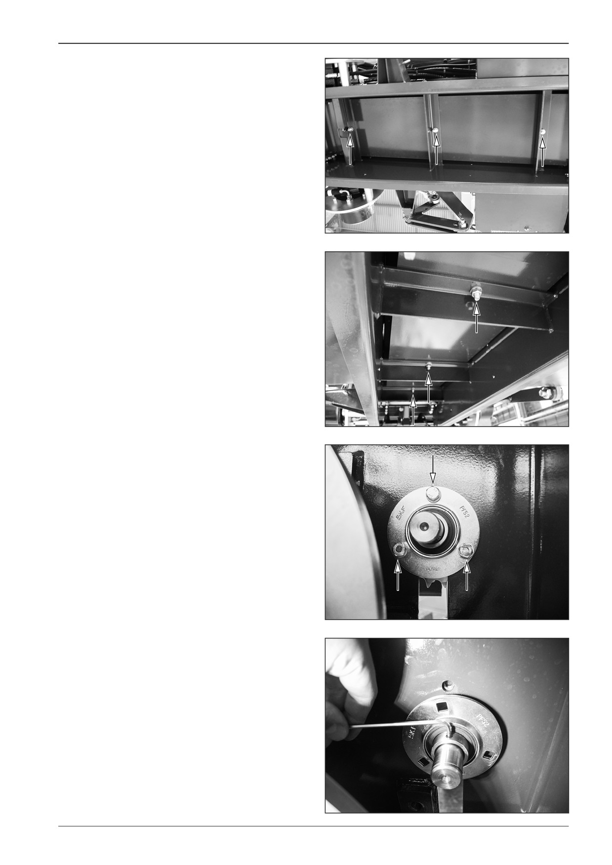
Remove the screws (3x).
D451560
D451559
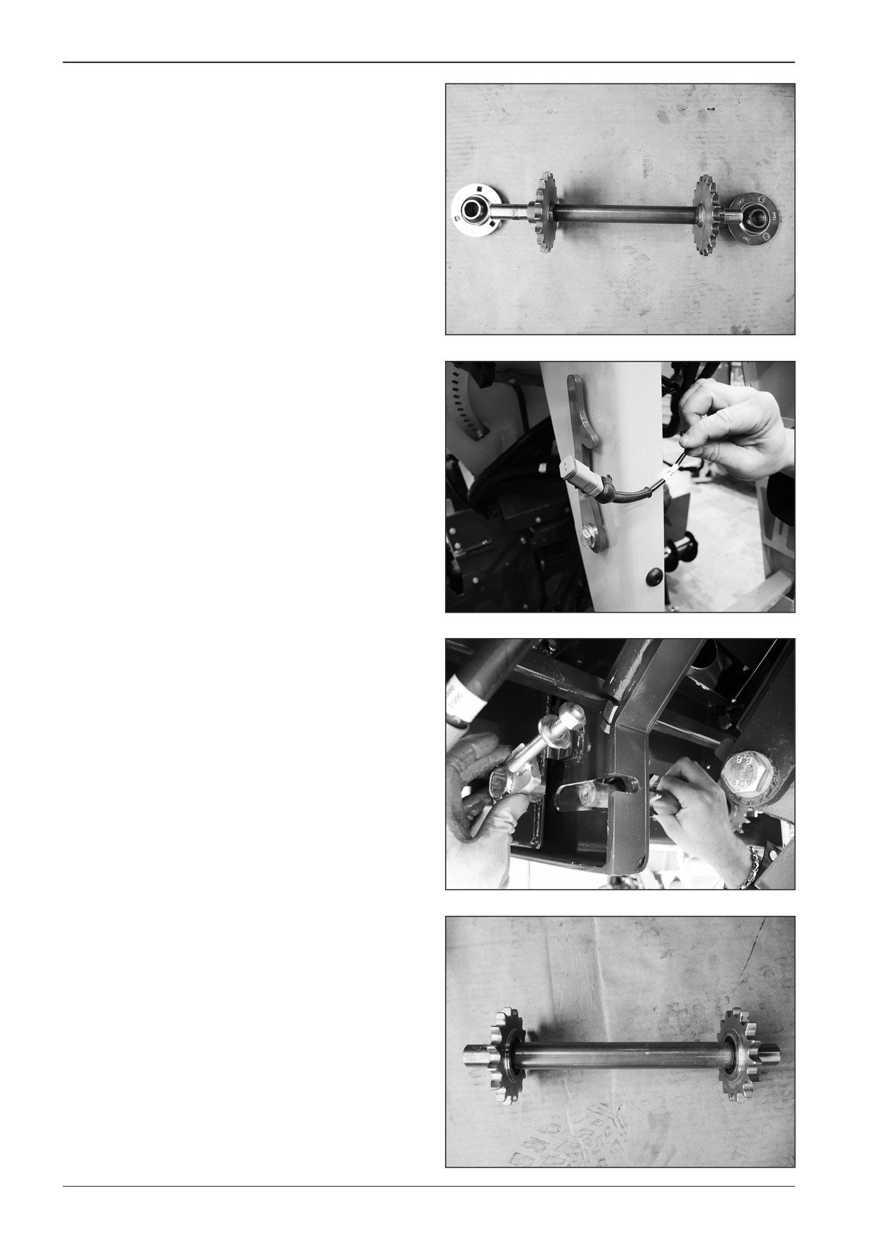
Remove the rear shaft with gear wheels.
•
Loosen the tension screws on the left and right side.
D451558
•
Remove the bearing housing on the left and right side.
D451561
F80W
173
14
Belt conveyors and augers
•
Pull out the shaft with the gear wheels.
D451562
Remove the front shaft with gear wheels.
•
Loosen the screws on both sides of the machine.
D451563
•
Remove chain tensioners.
D451564
•
Remove the shaft out of the machine.
D451565
174
F80W
WORKSHOP MANUAL
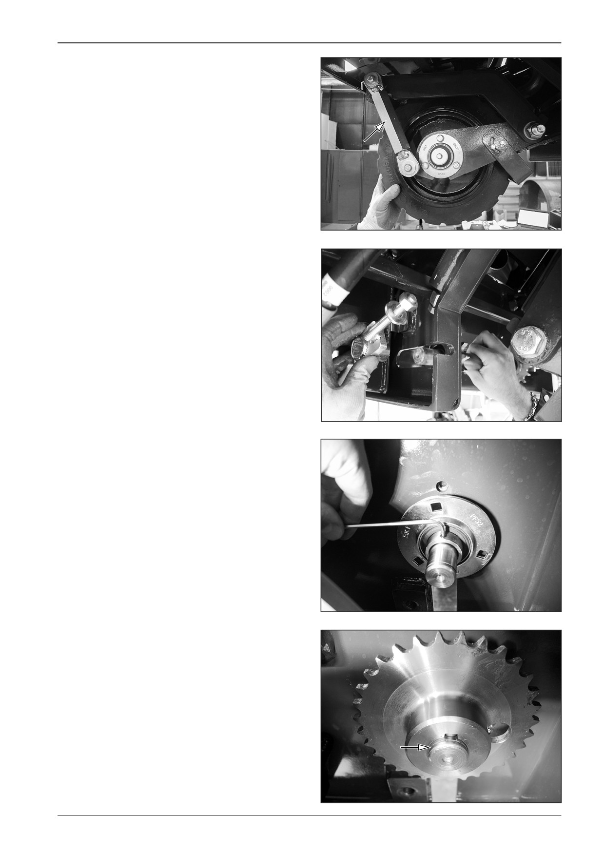
Having the front wheel levelled, completely screw the adjusting
mechanism of the front wheel height.
Take out the guide plate of the belt conveyor chain and replace
it with the new one.
D451566
Mount the front shaft and the chain tensioners.
D451564
Mount the rear shaft and the bearing housing on the left and
right side.
D451561
Note
Ensure that the groove for the lock ring can be seen when reas-
sembling the shaft.
D451570
F80W
175
14
Belt conveyors and augers
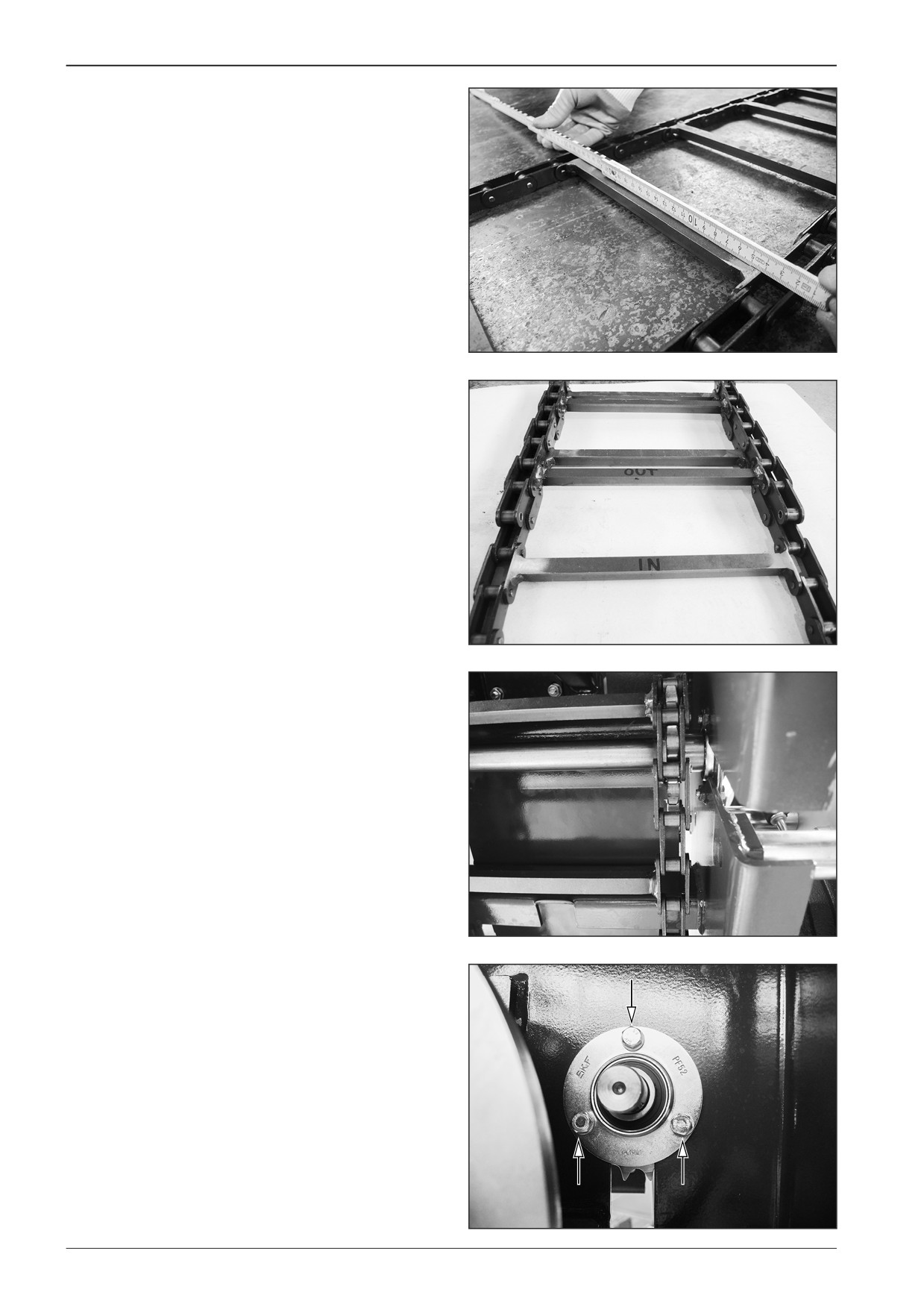
Mount the belt conveyor chain according to Chapter 14.3.
Note
Ensure that the conveyor chain is installed with the contact sur-
face to the chain guide plate.
451567
D451568
Ensure that the chain is at the same distance from the machine
frame on both sides.
D451569
Tighten the tension screws of the rear shaft on the left and right
side.
D451558
176
F80W
WORKSHOP MANUAL
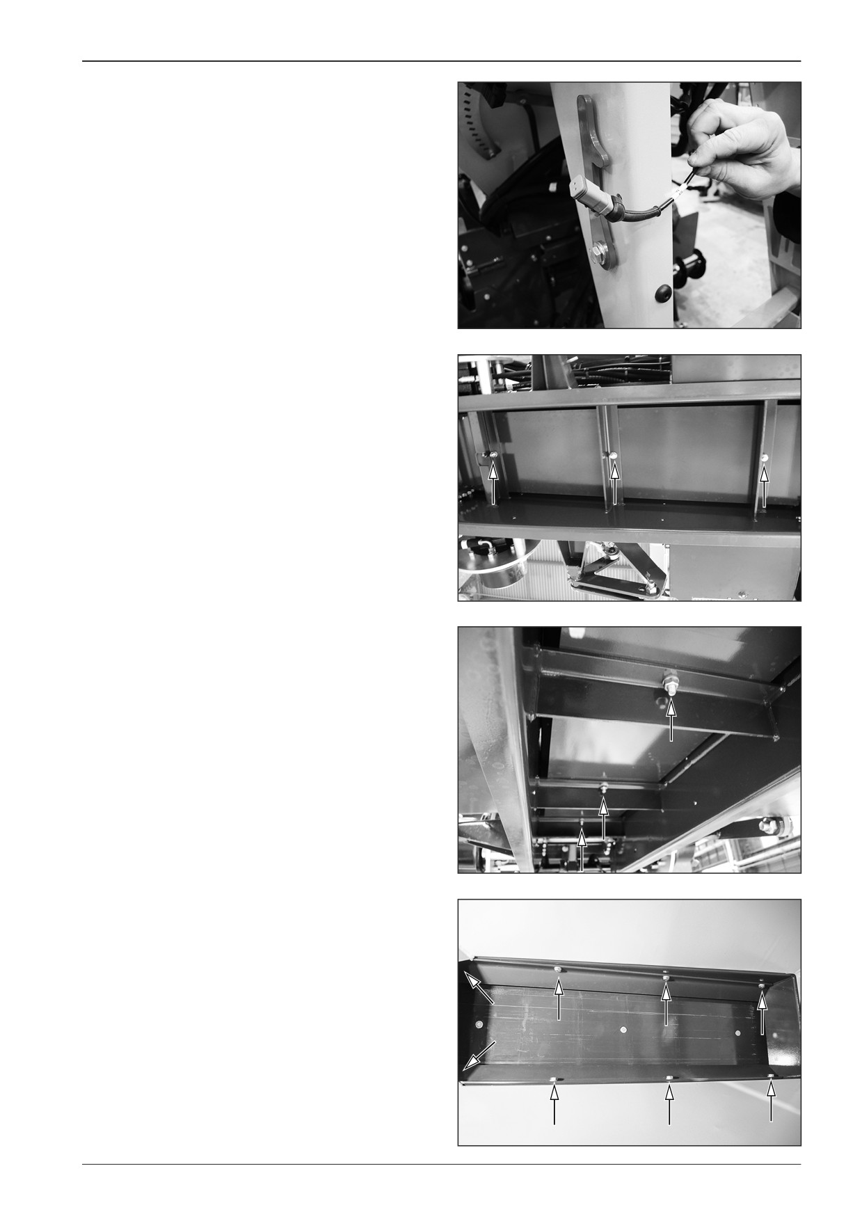
Tighten the screws of the front shaft on both sides of the ma-
chine.
D451563
Mount the screws (3x).
D451560
D451559
Mount the cover plates.
•
Mount the screws (8x).
Note
Secure the screws with the LOXEAL 83∙54 adhesive.
Mount the belt conveyor drive chain by proceeding in the re-
verse order according to Chapter 14.5.
Note
Observe the correct chain tension according to Chapter 14.4.
D451557
F80W
177
14
Belt conveyors and augers
Mount the rear wheels on the left and right side of the machine.
•
Mount the screws.
D451519
D451518
D451517
14.9.2
Cover plates
Remove the screws (8x).
Note
During reverse assembly glue the screws with the LOXEAL 83∙54
adhesive.
D451557
178
F80W
WORKSHOP MANUAL
15
Wiring
F80W
179
15
Wiring
4
2
1
3
3
5
3
D451647
15.1
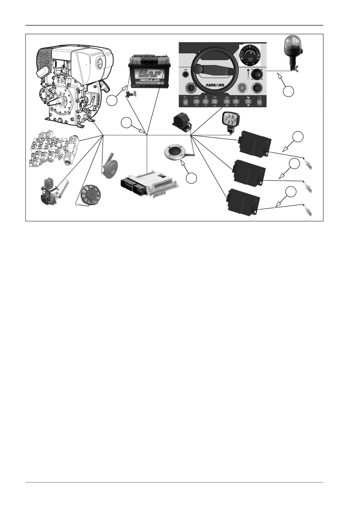
Description of basic components
1
Main harness
2
Battery cable
3
Gas ignition cable
4
Beacon cable
5
Foot switch cable
180
F80W
WORKSHOP MANUAL
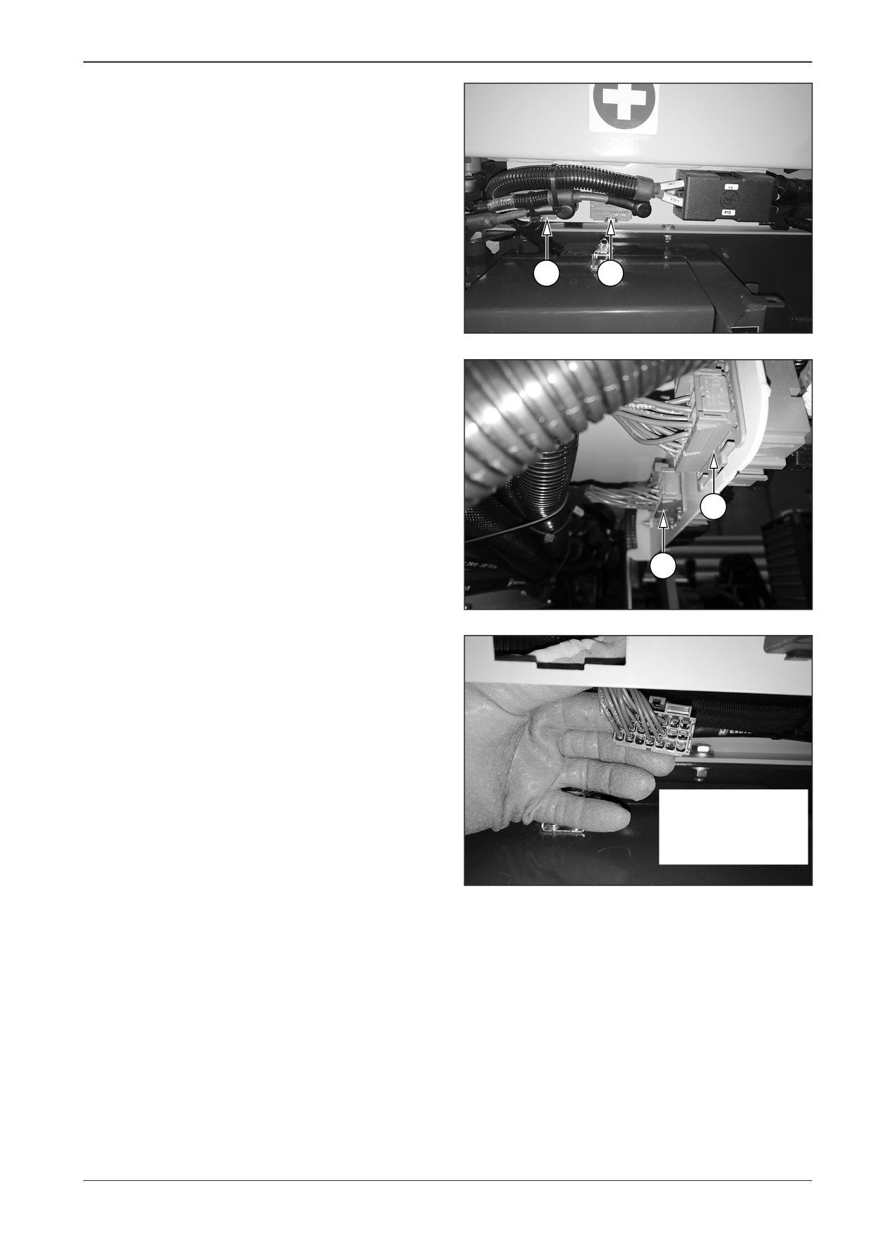
15.1.2
Central earthing points X6 and x7
Location of earthing points.
X7
X6
DD451042
X6
X7
DD451043
Numbering of pins.
1
4
7
10
13
16
19
2
5
8
11
14
17
20
3 6 9 12 15 18 21
DD451044
F80W
181

15
Wiring
15.2
Diagnostics
Perform diagnostics of electrical wiring on the machine with the closed gas bottle valve.
15.2.1
List of error codes displayed on the display
Code F
Short description
Causes and troubleshooting
F01
hydraulic oil sensor
short circuit to the ground detected - check the connection (X41, RD 141, WH 227)
F02
material feed sensor
short circuit to the ground detected - check the connection (X43, RD 143, WH 229)
F03
F03 brake pressure sensor
short circuit to the ground detected - check the connection (X42, RD 142, WH 228)
F04
engine cooling sensor
“short circuit on the battery detected - check the connection (X18:5, X35)”
F05
engine oil level sensor
“short circuit on the battery detected - check the connection (X17:4)”
F06
engine air filter sensor
“short circuit on the battery detected - check the connection (X18:3)”
F07
drive pump sensor
"short circuit to the ground or on the battery detected or no connection - check
the connection (X38, WH 214, WH 217, WH 222)"
F11
controller
“the most frequent cause: the controller is not calibrated; - parameter error 1
through 6: redundancy fault; - parameter error 7: not calibrated; - parameter error
8: error in the main channel; - parameter error 9: error in the redundant channel
(X36)”
F12
speed potentiometer
“the most frequent cause: an error in the main channel; - parameter error 1 through
(Paving speed controller)
6: redundancy fault; - parameter error 8: error in the main channel; - parameter
error 9: error in the redundant channel (X37)”
F13
travel mode switch
short circuit to the ground detected - check the connection (X53, RD 153, WH 243)
F14
material feed mode switch
short circuit to the ground detected - check the connection (X52, RD 152, WH 242)
F15
material feed direction switch
short circuit to the ground detected - check the connection (X51, RD 151, WH 240,
WH 241)
F16
screed height switch
short circuit to the ground detected - check the connection (X48, RD 148, WH 236,
WH 237)
F19
screed vibration switch
short circuit to the ground detected - check the connection (X49, RD 149, WH 238)
F21
horn button
short circuit to the ground detected - check the connection (X45, RD 145, WH 231)
F22
engine start switch
short circuit to the ground detected - check the connection (137)
F23
safety button
short circuit to the ground detected - check the connection (X44, RD 144, WH 230)
F24
screed extension switch - left,
short circuit to the ground detected - check the connection (X46, RD 146, WH 233)
inside
F25
screed extension switch - left,
short circuit to the ground detected - check the connection (X46, RD 146, WH 232)
outside
F26
screed extension switch - right,
short circuit to the ground detected - check the connection (X47, RD 147, WH 234)
inside
F27
screed extension switch - right,
short circuit to the ground detected - check the connection (X47, RD 147, WH 235)
outside
F28
forward control switch
short circuit to the ground detected - check the connection (X36)
F29
rearward control switch
short circuit to the ground detected - check the connection (X36)
F30
control neutral position switch
short circuit to the ground detected - check the connection (X36)
F31
travel pump - forward
"short circuit to the ground or on the battery detected or no connection - check
the connection and the coil (X65, Y12, WH 263, WH 265, WH 266)"
F32
travel pump - rearward
"short circuit to the ground or on the battery detected or no connection - check
the connection and the coil (X66, Y13, WH 264, WH 266)"
F33
drive pump safety
"short circuit to the ground or on the battery detected or no connection - check
the connection and the coil (X65, X66, Y12, Y13, WH 263, WH 264, WH 265, WH 266)"
F34
brake release output
"short circuit to the ground or on the battery detected or no connection - check
the connection and the coil (X60, Y7, WH 256, WH 257)"
F35
brake release safety
"short circuit to the ground or on the battery detected or no connection - check
the connection and the coil (X60, Y7, WH 256, WH 257)"
F36
material feed forward valve
"short circuit to the ground or on the battery detected or no connection - check
the connection and the coil (X54, Y1, WH 244, WH 246, WH 247)"
182
F80W

WORKSHOP MANUAL
Code F
Short description
Causes and troubleshooting
F37
material feed rearward valve
"short circuit to the ground or on the battery detected or no connection - check
the connection and the coil (X55, Y2, WH 245, WH 247)"
F38
material feed safety
"short circuit to the ground or on the battery detected or no connection - check
the connection and the coil (X54, X55, Y1, Y2, WH 244, WH 245, WH 246, WH 247)"
F39
floating mode valve
"short circuit to the ground or on the battery detected or no connection - check
the connection and the coil (X61, Y8, WH 258, WH 259)"
F40
floating mode safety
"short circuit to the ground or on the battery detected or no connection - check
the connection and the coil (X61, Y8, WH 258, WH 259)"
F41
screed activation valve
"short circuit to the ground or on the battery detected or no connection - check
the connection and the coil (X62, Y9, WH 260, BN 326)"
F42
screed lifting valve
"short circuit to the ground or on the battery detected or no connection - check
the connection and the coil (X63, Y10, WH 261, BN 327)"
F43
extension valve - to the left,
"short circuit to the ground or on the battery detected or no connection - check
outside
the connection and the coil (X56, Y3, WH 248, WH 250, WH 251)"
F44
extension valve - to the left,
"short circuit to the ground or on the battery detected or no connection - check
inside
the connection and the coil (X57, Y4, WH 249, WH 251)"
F45
left extension safety
"short circuit to the ground or on the battery detected or no connection - check
the connection and the coil (X56, X57, Y3, Y4, WH 248, WH 249, WH 250, WH 251)"
F46
extension valve - to the right,
"short circuit to the ground or on the battery detected or no connection - check
outside
the connection and the coil (X59, Y6, WH 253, WH 255)"
F47
extension valve - to the right
"short circuit to the ground or on the battery detected or no connection - check
inside
the connection and the coil (X58, Y5, WH 252, WH 254, WH 255)"
F48
right extension safety
"short circuit to the ground or on the battery detected or no connection - check
the connection and the coil (X58, X59, Y5, Y6, WH 252, WH 253, WH 254, WH 255)"
F49
vibration valve
"short circuit to the ground or on the battery detected or no connection - check
the connection and the coil (X64, Y11, WH 262, BN 328)"
F50
cooling fan output
"short circuit to the ground or on the battery detected or no connection - check
the connection and the relay (X68, K2, WH 268, BN 330)"
F51
alarm backup output
"short circuit to the ground or on the battery detected or no connection - check
the connection and the relay (X70, K4, WH 270, BN 332)"
F52
engine start output
"short circuit to the ground or on the battery detected or no connection - check
the connection and the relay (X67, K1, WH 267, BN 329)"
F53
fuel valve output
"short circuit to the ground or on the battery detected or no connection - check
the connection (X17:5, WH 205)"
F54
conveyor output, lower side
"short circuit to the ground or on the battery detected or no connection - check
the connection and the coil (X54, X55, Y1, Y2, WH 244, WH 245, WH 246, WH 247)"
F55
left extension output, lower side
"short circuit to the ground or on the battery detected or no connection - check
the connection and the coil (X56, X57, Y3, Y4, WH 248, WH 249, WH 250, WH 251)"
F56
right extension output, lower side
"short circuit to the ground or on the battery detected or no connection - check
the connection and the coil (X58, X59, Y5, Y6, WH 252, WH 253, WH 254, WH 255)"
F57
drive pump output, lower side
"short circuit to the ground or on the battery detected or no connection - check
the connection and the coil (X65, X66, Y12, Y13, WH 263, WH 264, WH 265, WH 266)"
F58
brake release output, lower side
"short circuit to the ground or on the battery detected or no connection - check
the connection and the coil (X60, Y7, WH 256, WH 257)"
F59
floating screed output, lower side
"short circuit to the ground or on the battery detected or no connection - check
the connection and the coil (X61, Y8, WH 258, WH 259)"
F60
brake not adjusted
"pressure in the brake release hydraulic system although it should be zero - check
the sensor and the pressure valve (X42, X60, S6, Y7, RD 142, WH 228, WH 256,
WH 257)"
F61
brake not released
"zero pressure in the brake release hydraulic system although it should not be
zero - check the sensor and the pressure valve (X42, X60, S6, Y7, RD 142, WH 228,
WH 256, WH 257)”
F62
beacon light output
"short circuit to the ground or on the battery detected or no connection - check
the connection and the relay (X71, K5, WH 271, BN 333)"
F63
neutral switch general error
“control safety check failed - check control connection (X36)”
F64
forward switch general error
“control safety check failed - check control connection (X36)”
F80W
183
15
Wiring
Code F
Short description
Causes and troubleshooting
F65
rearward switch general error
“control safety check failed - check control connection (X36)”
F70
screed temperature sensor
“short circuit to the ground detected or no connection - check the connection and
the sensor”
F71
glowing of ignition 1
short circuit to the ground detected - check the connection (X27, A6, RD 126,
WH 206)
F72
glowing of ignition 2
short circuit to the ground detected - check the connection (X28, A7, RD 127,
WH 207)
F73
glowing of ignition 3
short circuit to the ground detected - check the connection (X29, A8, RD 128,
WH 208)
F74
glowing switch
short circuit to the ground detected - check the connection (X50, S14, RD 150,
WH 239)
F75
fault of ignition 1
"ignition box 1 indicates a fault - check the gas flow and burner ignition
1 (X73, X76, I1)"
F76
fault of ignition 2
"ignition box 2 indicates a fault - check the gas flow and burner ignition
2 (X74, X77, I2)”
F77
fault of ignition 3
"ignition box 3 indicates a fault - check the gas flow and burner ignition
3 (X75, X78, I3)"
F78
glowing output
"short circuit to the ground or on the battery detected or no connection - check
the connection and the relay (X72, K6, WH 272, BN 334)"
F79
horn output
"short circuit to the ground or on the battery detected or no connection - check
the connection and the relay (X69, K3, WH 269, BN 331)"
F80
electronics temperature too high
the internal temperature of the electronic control unit exceeds 80°C
F81
air filter service required
the diesel engine requires air filter service
184
F80W
WORKSHOP MANUAL
15.2.2
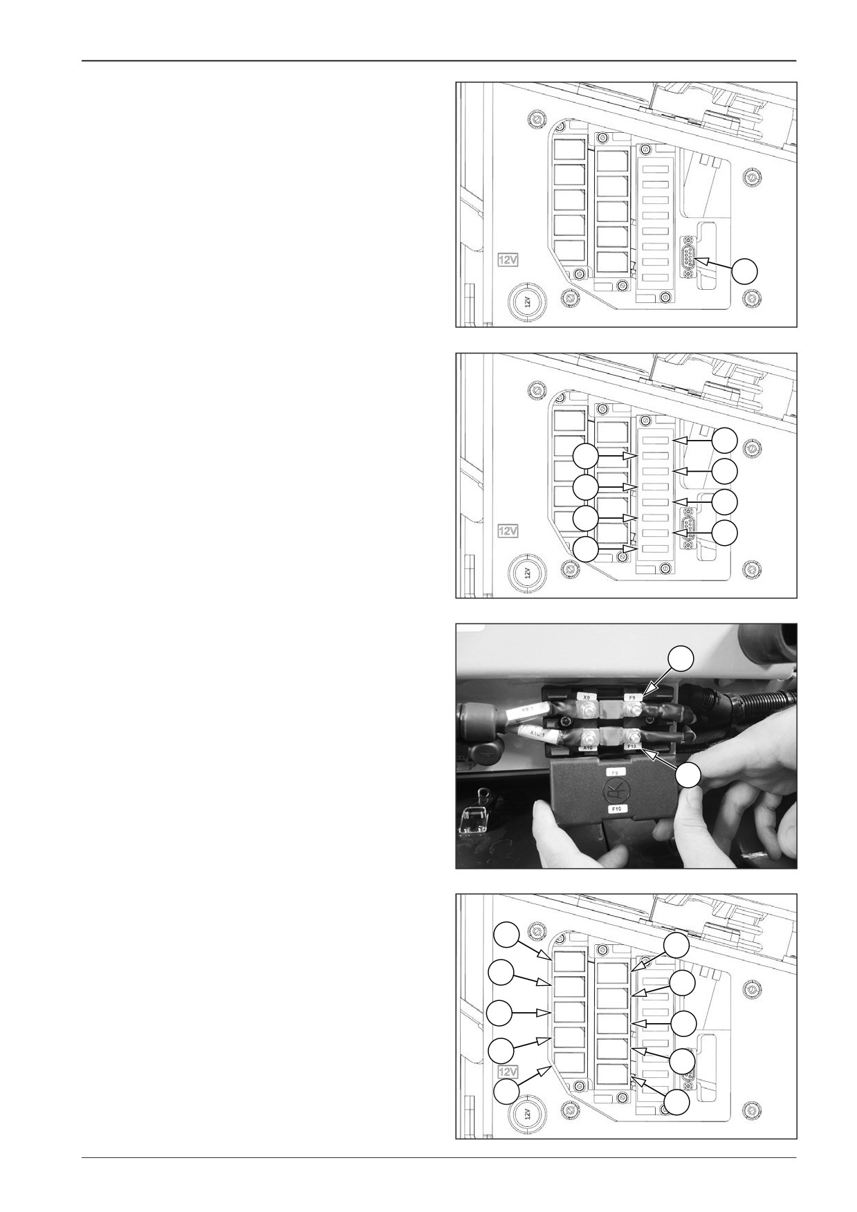
Fuse box
1
Diagnostics connector
1
451046
F1
Fuse at the input of the power supply
of the control unit
(3 A)
F2
Fuse at the output of the power supply of the
control unit
(25 A)
F3
Oil cooler fan fuse
(15 A)
F1
F4
Horn and reverse travel with horn fuse
(5 A)
F2
F5
Fuse of beacon and auger area lighting
(7.5 A)
F3
F4
F6
Screed heating fuse
(5 A)
F5
F7
Universal display fuse
(2 A)
F6
F7
F8
Fuse of the power supply of the electronics
F8
of the control unit
(5 A)
451045
F9
Main fuse
(30 A)
F10
Starter fuse
(30 A)
F9
F10
DD451002
K1
Engine starting relay
K2
Oil cooler relay
K1
K3
Horn relay
K6
K4
Relay of the warning acoustic signal of the reverse run
K2
K5
Warning beacon relay;
K7
K6
Screed heating relay
K3
K7
Not used
K8
K8
Not used
K4
K9
K9
Not used
K10
Screed heating relay
K5
K10
451047
F80W
185
15
Wiring
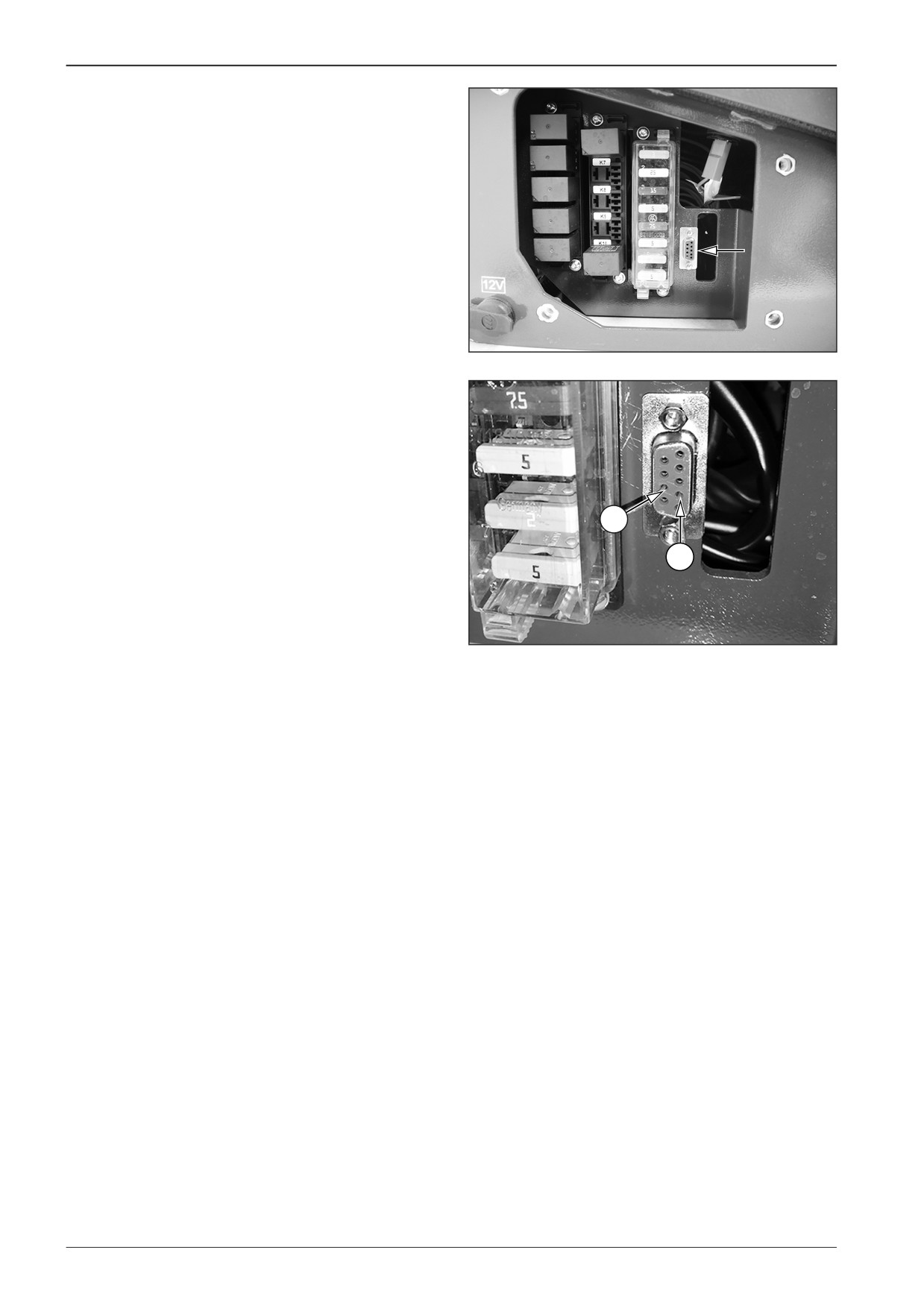
15.2.3 Diagnostics socket
Location of the diagnostic socket.
D451648
Basic description of the diagnostic socket.
1
CAN-Low (pin 7)
2
CAN-High (pin 2)
2
1
DD451062
186
F80W
WORKSHOP MANUAL
15.2.3.1
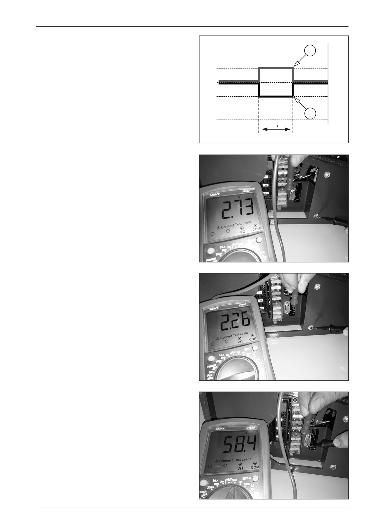
Measuring of the CAN BUS data bus
2
Measure 2.5 - 3.5 V at the diagnostic socket of CAN-High pin (2).
Measure 1.5 - 2.5 V at the diagnostic socket of CAN-Low pin (1).
3,5V
2,5V
1,5V
1
0V
2 S
DD451027
15.2.3.1.1
Measuring voltage of the CAN BUS
data bus
Turn the key in the ignition box to the “I“ position.
Measure a voltage at the range of 2.5 - 3.5 V at the CAN-High
output (pin 2).
DD451028
Measure a voltage at the range of 1.5 - 2.5 V at the CAN-Low
output (pin 7).
DD451029
15.2.3.1.2
Measuring resistance of the
CAN BUS data bus
Measure a resistance of approximately 60 Ω between CAN-High
(pin 2) and CAN-Low (pin 7) outputs.
DD451030
F80W
187
15
Wiring
15.2.4
Communication with the control unit A2
by means of Bodas - service 3.5
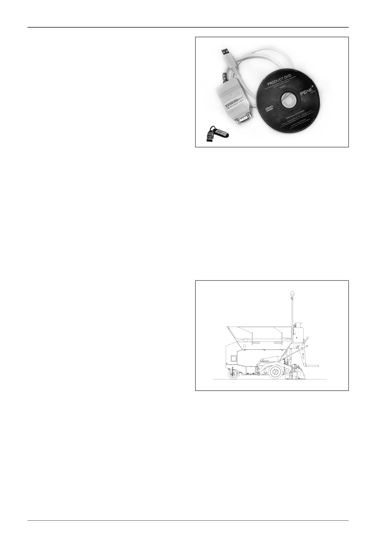
To communicate with the control unit, Bodas - service 3.5 must
be installed.
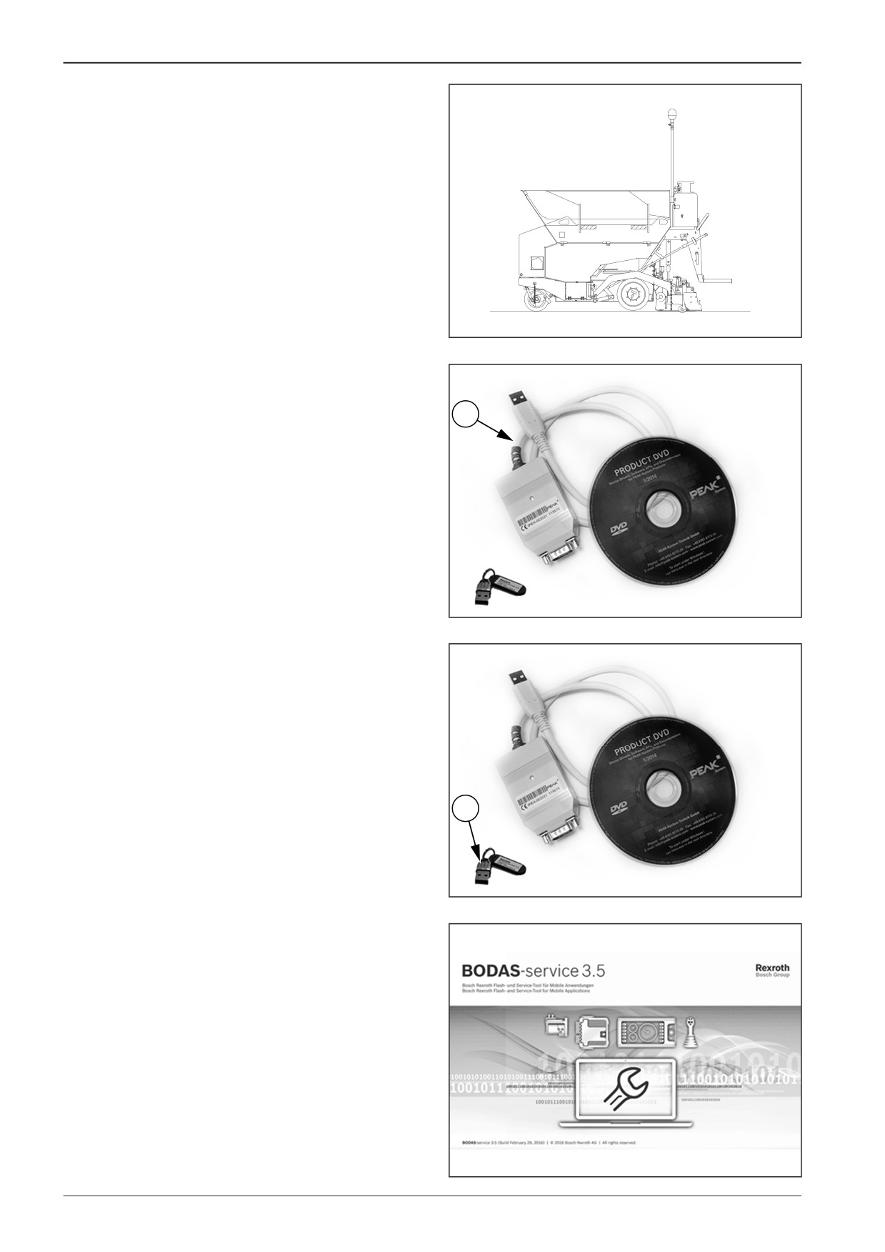
Components necessary to connect to the machine:
•
Bodas - service 3.5 software
•
connecting cable and a USB key.
D451649
15.2.4.1
Connecting the machine to PC
Park the machine on a solid and flat surface.
451C003
188
F80W
WORKSHOP MANUAL
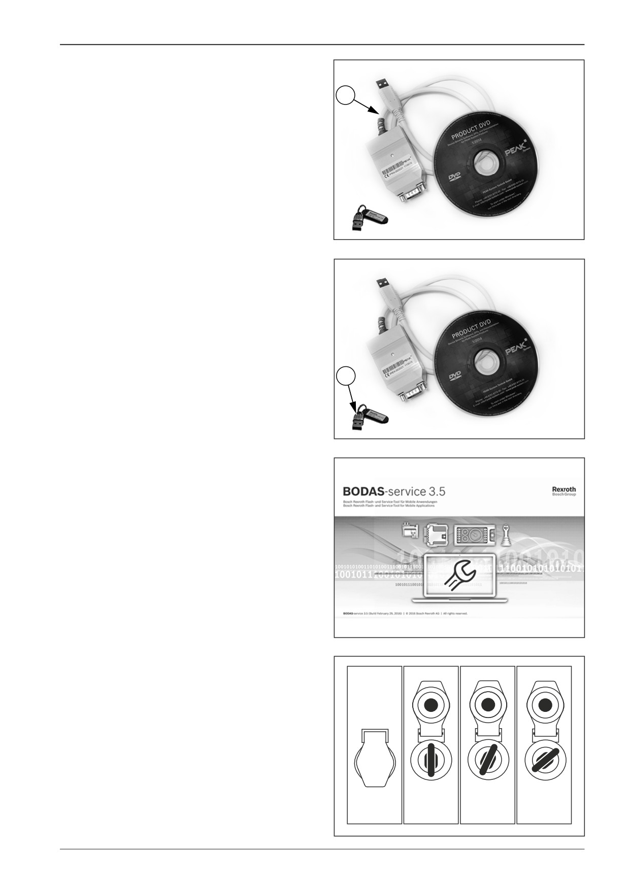
Connect the computer to the machine using the connecting
cable (1).
1
D451C001
Connect the USB key (2) to the computer.
2
D451C002
Start the Bodas software.
D451C004
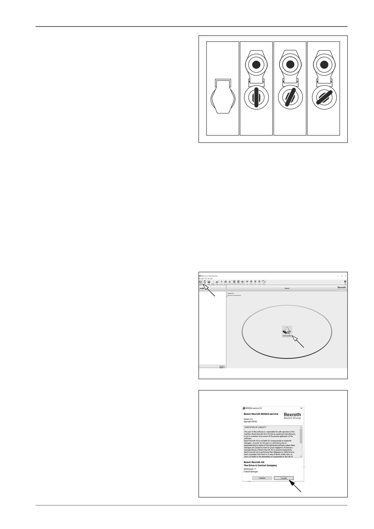
Turn the key in the ignition box to the “I“ position.
0
I
II
380K0022
F80W
189
15
Wiring
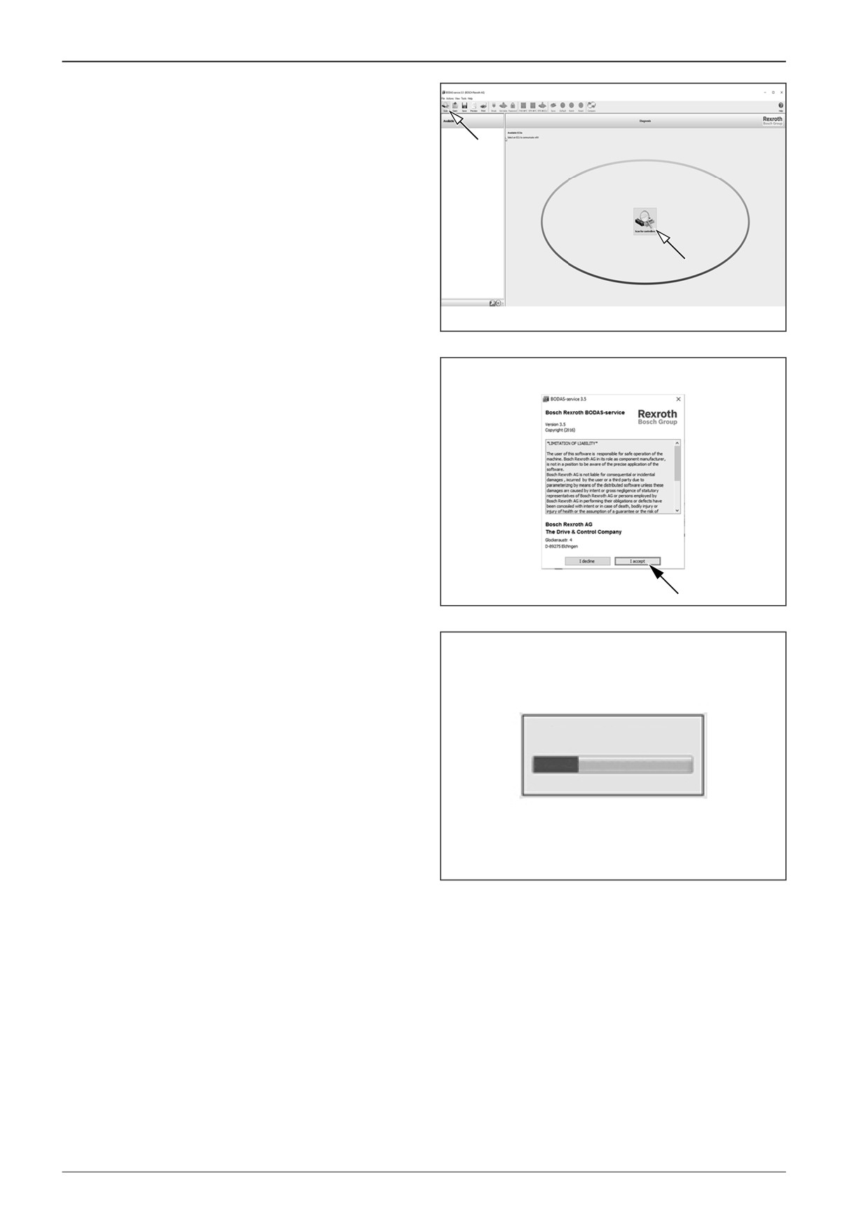
Press the “Scan” icon for connecting the computer.
D451C005
Press the button to confirm licence conditions.
D451C006
The computer is connecting.
Number of found controllers: 0
Scanning for controllers
D451C007
190
F80W
WORKSHOP MANUAL
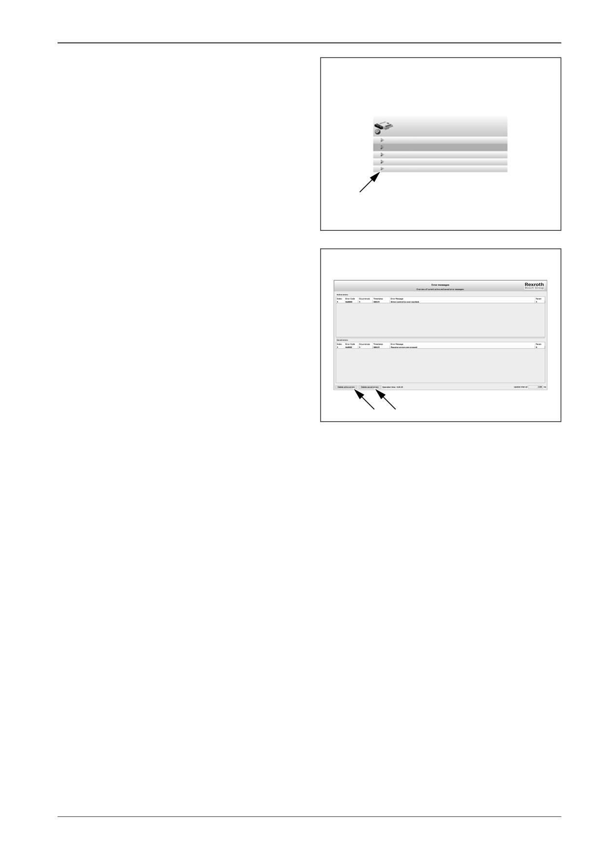
15.2.4.2
Uploading and deleting errors
If the name of the computer and software version are written
in red, some errors are active. If they are written in black, the
computer is without errors.
SN: 00056112
Unroll the “Error Messages” tab.
RC28-14/30
HwCode:0000O6
AFW150-2
Errors detected
Parameter
Processdata
I/O Status view
Custom view
Error messages
D451C035
A list of error will be displayed.
To delete errors, press the “Delete active errors” and “Delete
saved errors” buttons.
Note
If any of the errors remains active, they will appear in the list
after deletion. Repair the failures!
D451C036
F80W
191
15
Wiring
15.2.4.3
Check of parameters
The check of parameters serves for the evaluation of faults or for
checking the values on inputs and outputs of the RC unit.
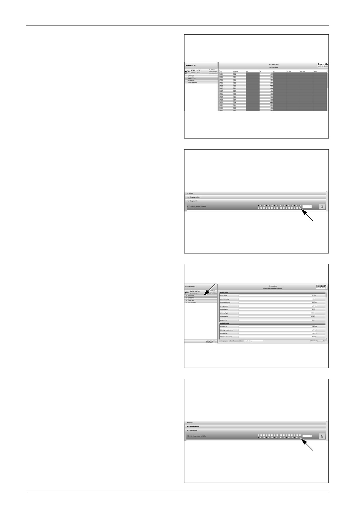
There are two ways how to display the values.
Method No. 1
Display the “I/O Status view” tab - the check of the voltage level
on individual pins.
D451C038
Method No. 2
Select item “4. Setup”.
Check the last box in “4.3.1 Service process variables”.
D451C039
Parameters can be seen in the “Processdata” tab.
D451C040
To remove the fault or check the parameters, uncheck the last
box in “4.3.1 Service process variables”.
D451C039
192
F80W
WORKSHOP MANUAL
15.2.5
Display measurement
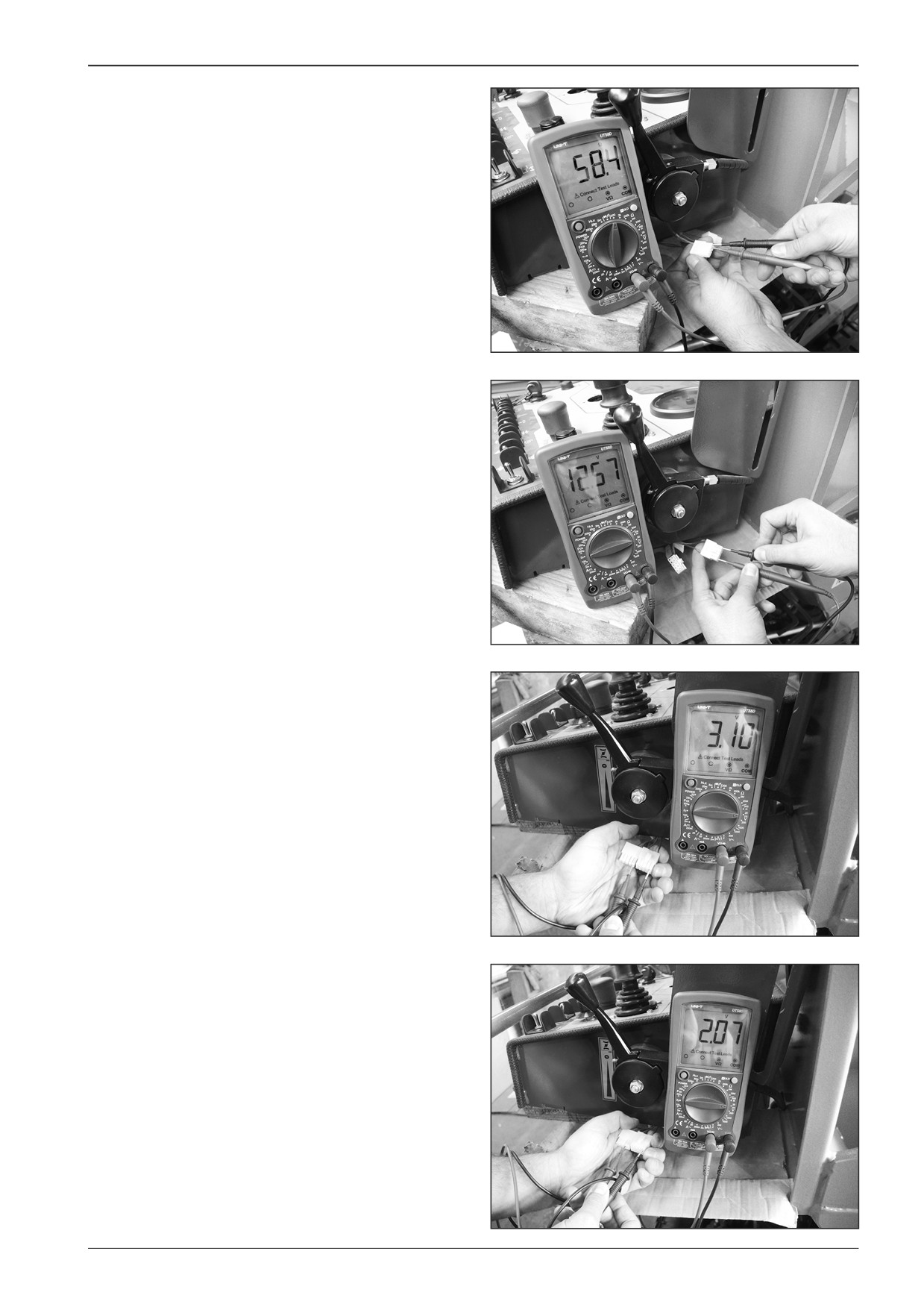
Disconnect connectors X33 and X40 from display A3.
Measure a resistance of approximately 60 Ω on the connector
X40 between the blue and yellow wire.
DD451006
Turn the key in the ignition box to the “I“ position.
Measure the voltage of battery (12 V) on the connector X33 be-
tween the wires.
DD451008
Measure the voltage of approximately 3.1 V on the connector
X40 between the yellow wire no. 6 and the machine casing (the
brown wire of connector X33).
DD451007
Measure the voltage of approximately 2.07 V on the connector
X40 between the blue wire no. 7 and the machine casing (the
brown wire of connector X33).
DD451009
F80W
193
15
Wiring
15.2.6
Foot switch measurement
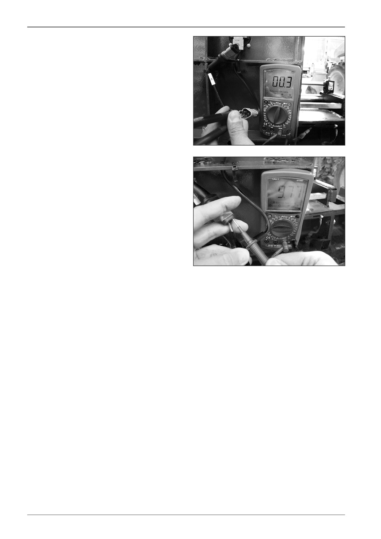
Disconnect the connector X44 of the foot switch S8.
Measure the resistance on the connector X44 on the switch side
between pin A and pin B. The measured value will be displayed
after activating the foot switch.
DD451010
Turn the key in the ignition box to the “I“ position.
Measure the voltage of approximately 9.77 V at the foot switch
on the connector X44 between pin A and pin B.
If a different voltage value is measured, check:
•
fuse F1 (3 A)
•
wiring between the ignition box (pin 15) and the connector
X44 (pin A)
•
wiring between the connector X44 (pin B) and the connec-
tor X34 of the control unit (pin 42).
DD451011
194
F80W
WORKSHOP MANUAL
15.2.7
Travel controller measurement
In case of a failure of the travel controller, error messages F11,
F28, F29 or F30, F63, F64 and F65 will be displayed on the dis-
play.
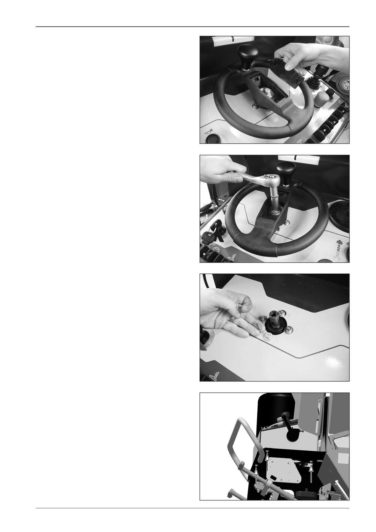
Remove the steering wheel:
•
Remove the cover
D451461
•
Remove the screw
D451462
•
Take out the steering wheel and remove the screws
D451463
Remove the control panel:
•
Remove the screws (3x)
DD451004
F80W
195
15
Wiring
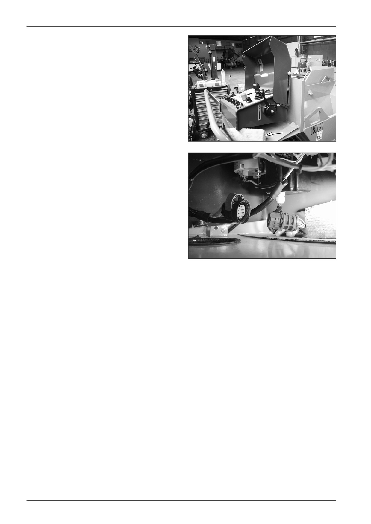
•
Support the control panel
DD451003
•
Disconnect the connector X36
Measure the voltage on the connector X36 on the machine side:
•
approximately 2.71 V between pin 14 and pin 3.
•
approximately 5.08 V between pin 14 and pin 7.
•
approximately 2.71 V between pin 14 and pin 8.
•
approximately 5.08 V between pin 14 and pin
•
of the battery (12 V) between pin 14 and pin 9.
Measure the resistance on the connector X36 on the travel con-
troller side:
•
0.8 kΩ between pin 6 and pin 7 with the travel controller set
DD451012
in the forward position
•
3.1 kΩ between pin 6 and pin 7 with the travel controller set
in the neutral position
•
5.4 kΩ between pin 6 and pin 7 with the travel controller set
in the reverse position
•
approximately 5.5 kΩ between pin 13 and pin 12 with the
travel controller set in the forward position
•
3.1 kΩ between pin 13 and pin 12 with the travel controller
set in the neutral position
•
0.8 kΩ between pin 13 and pin 12 with the travel controller
set in the reverse position
•
6.2 kΩ between pin 5 and pin 7 with the travel controller set
in any position
•
6.2 kΩ between pin 14 and pin 12 with the travel controller
set in the any position
196
F80W
WORKSHOP MANUAL
15.2.8
Paving speed selector measurement
Measure the paving speed selector on the machine with the
switched off battery disconnecter and with the closed gas bot-
tle valve.
Remove the paving speed selector.
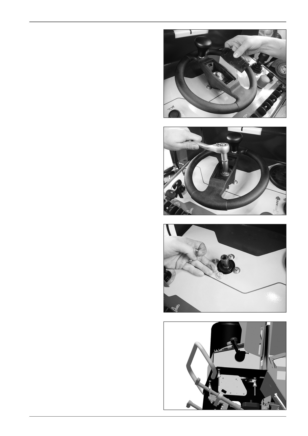
•
Remove the steering wheel.
--
Remove the cover.
D451461
--
Remove the screw.
D451462
--
Take out the steering wheel and remove the screws.
D451463
•
Remove the control panel.
--
Remove the screws (3x).
DD451004
F80W
197
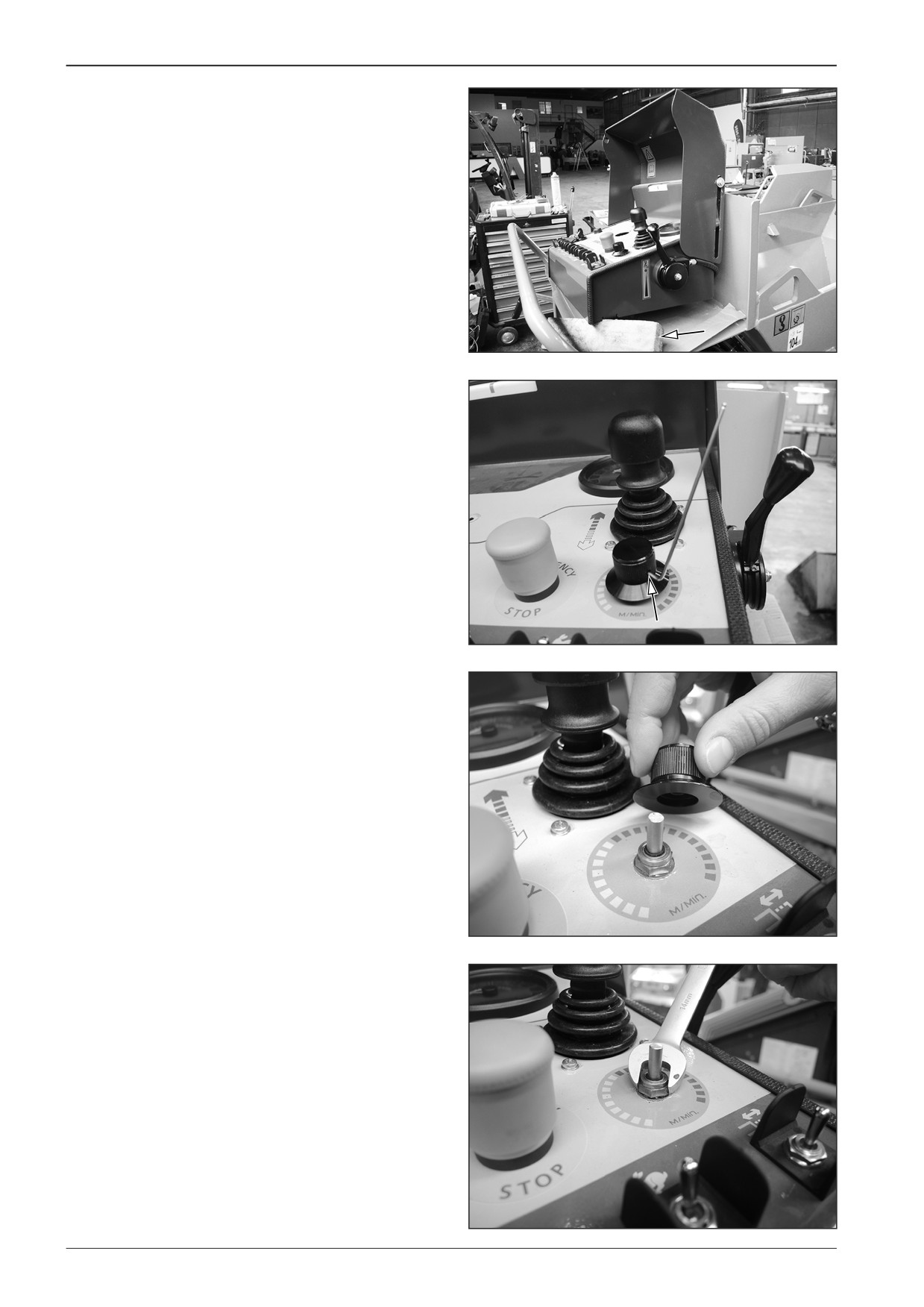
15
Wiring
•
Support the control panel.
DD451003
•
Remove the paving speed selector regulator.
--
Loosen the screw.
DD451014
DD451015
--
Remove the nut.
DD451016
198
F80W
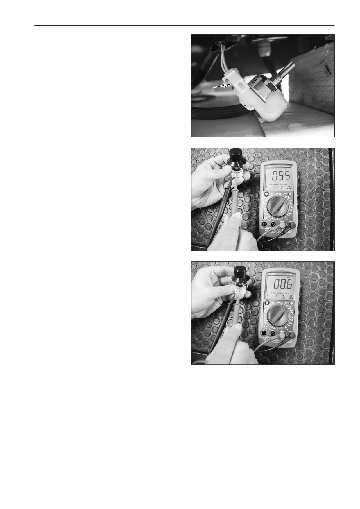
WORKSHOP MANUAL
- Slightly pull out the selector and disconnect the X37 connec-
tor.
DD451017
Measure the resistance of the paving speed selector.
•
6.2 Ω between pin 1 and pin 3
•
5.5 Ω between pin 1 and pin 2 in the minimum selector
position
•
0.6 Ω between pin 1 and pin 2 in the maximum selector
position
•
0.6 Ω between pin 2 and pin 3 in the minimum selector
position
•
5.5 Ω between pin 2 and pin 3 in the maximum selector
position
DD451018
DD451019
F80W
199
15
Wiring
15.3
Calibration
Perform calibration on the machine with the closed gas bottle
valve.
15.3.1
Connecting the machine to PC
Park the machine on a solid and flat surface.
451C003
Connect the computer to the machine using the connecting
cable (1).
1
D451C001
Connect the USB key to the computer (2).
2
D451C002
Start the Bodas software.
D451C004
200
F80W
WORKSHOP MANUAL
Turn the key in the ignition box to the “I“ position.
0
I
II
380K0022
15.3.2
Calibration of the travel controller and
the paving speed selector
Press the “Scan” icon for connecting the computer.
D451C005
Press the button to confirm licence conditions.
D451C006
F80W
201
15
Wiring
The computer is connecting.
Number of found controllers: 0
Scanning for controllers
D451C007
Unroll the “Parameter” tab.
SN: 00065112
RC28-14/30
HwCode: 0000D6
AFW150-2
Parameter
Processdata
I/O Status view
Custom view
D451C008
Select - 1.8 “Calibration operation”
Confirm - 1.8.1 “Calibrate”
1.8 Calibration operation
1.8.1 driving lever
Minimum
Maximum
Current
Accept
Calibrate
0.67V
3.97V
- - -
STD
1.8.2 driving lever middle
Saved
Current
Accept
Calibrate
2.20V
- - -
STD
Minimum
Maximum
Current
1.8.3 speed poti
Accept
Calibrate
0.62V
4.20V
- - -
STD
451C009
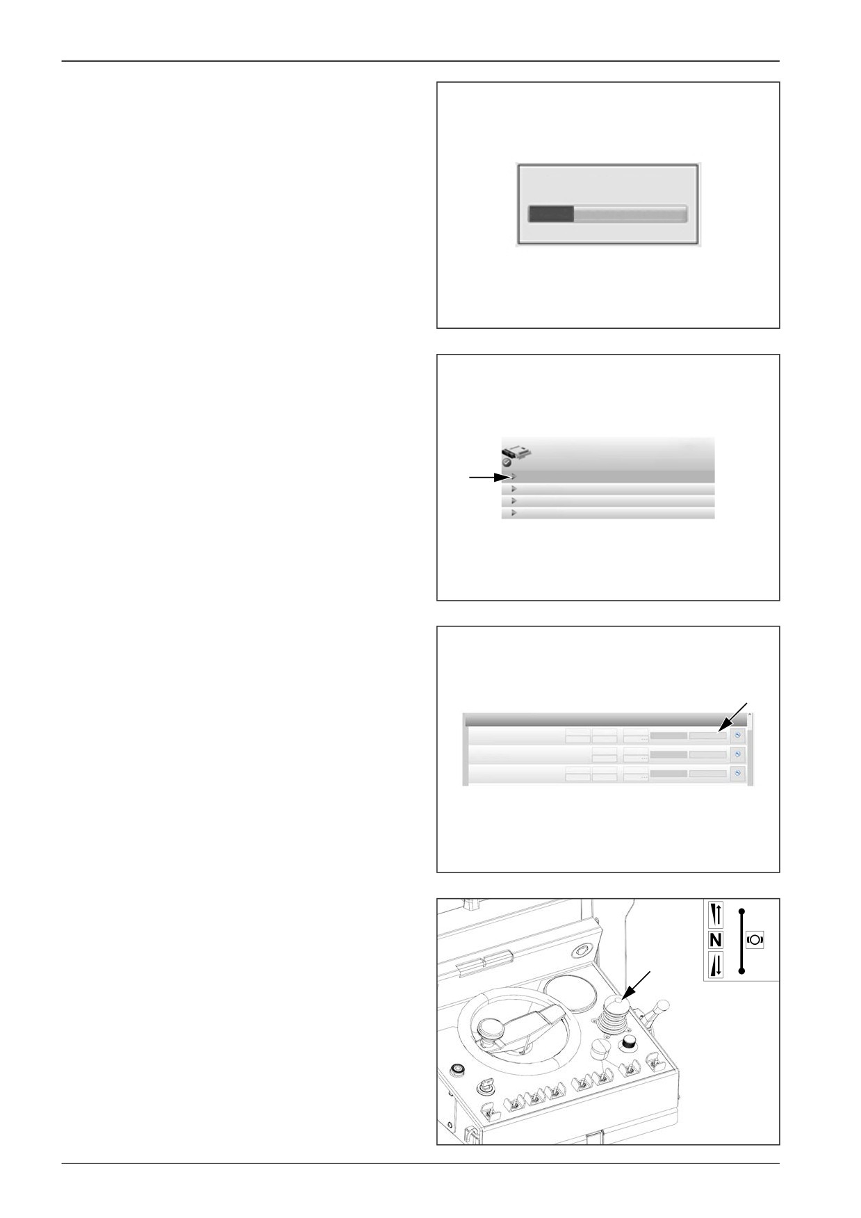
Set the position for reverse travel by the travel controller.
F
0
P
R
451C010
202
F80W
WORKSHOP MANUAL
Confirm it by pressing the “Set min value” button.
The red highlighting means that the value has been changed.
1.8 Calibration operation
1.8.1 driving lever
Minimum
Maximum
Current
Set min value
Cancel
0.57V
3.97V
0.56V
STD
Saved
Current
Accept
1.8.2 driving lever middle
2.20V
- - -
Adjust
STD
1.8.3 speed poti
Minimum
Maximum
Current
Accept
Calibrate
0.62V
4.20V
- - -
STD
D451C011
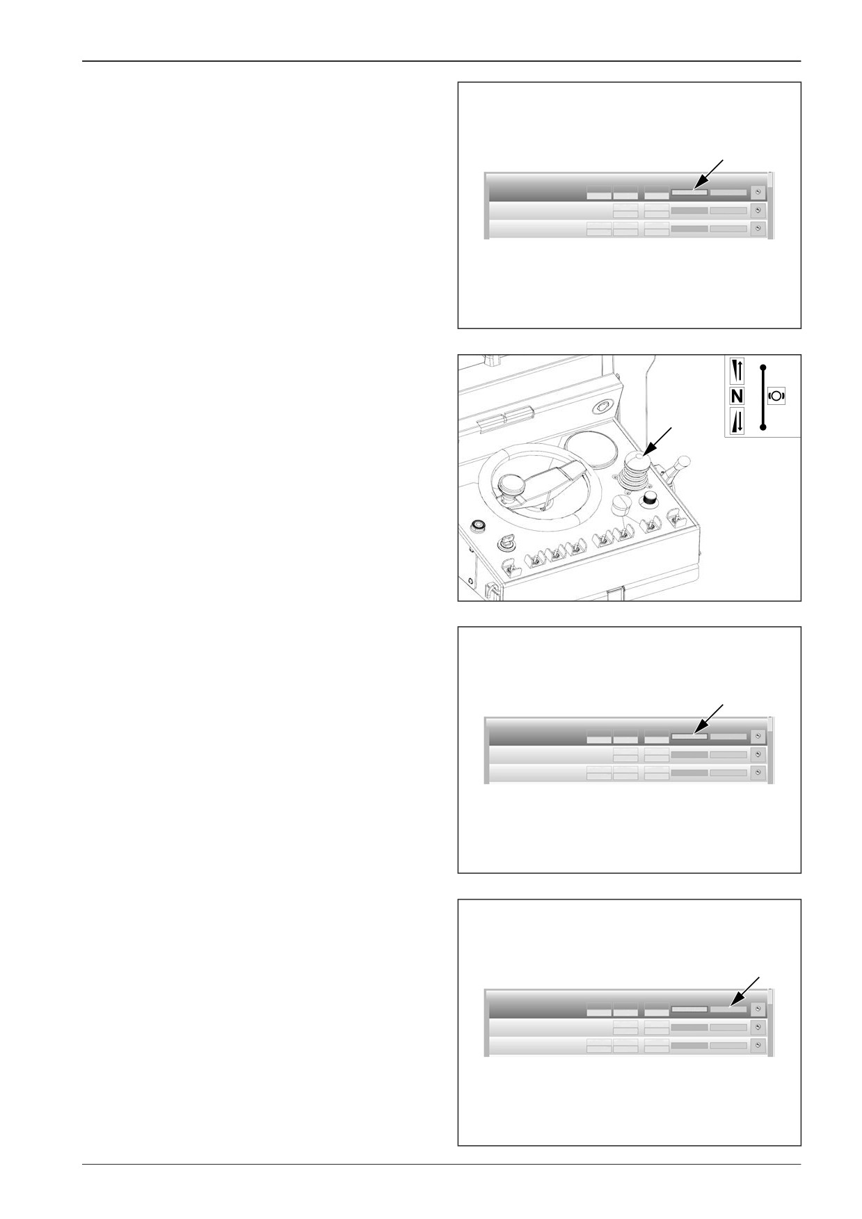
Set the position for forward travel by the travel controller.
F
0
P
R
451C010
Confirm it by pressing the “Set max value” button.
1.8 Calibration operation
1.8.1 driving lever
Minimum
Maximum
Current
Set max value
Cancel
0.57V
3.97V
4.12V
STD
Saved
Current
Accept
1.8.2 driving lever middle
2.20V
- - -
Adjust
STD
Minimum
Maximum
Current
1.8.3 speed poti
0.62V
4.20V
- - -
Accept
Calibrate
STD
D451C012
After setting both values press “Cancel” to end the calibration.
1.8 Calibration operation
1.8.1 driving lever
Minimum
Maximum
Current
Set max value
Cancel
0.57V
3.97V
4.12V
STD
Saved
Current
Accept
1.8.2 driving lever middle
2.20V
- - -
Adjust
STD
1.8.3 speed poti
Minimum
Maximum
Current
Accept
Calibrate
0.62V
4.20V
- - -
STD
D451C013
F80W
203
15
Wiring
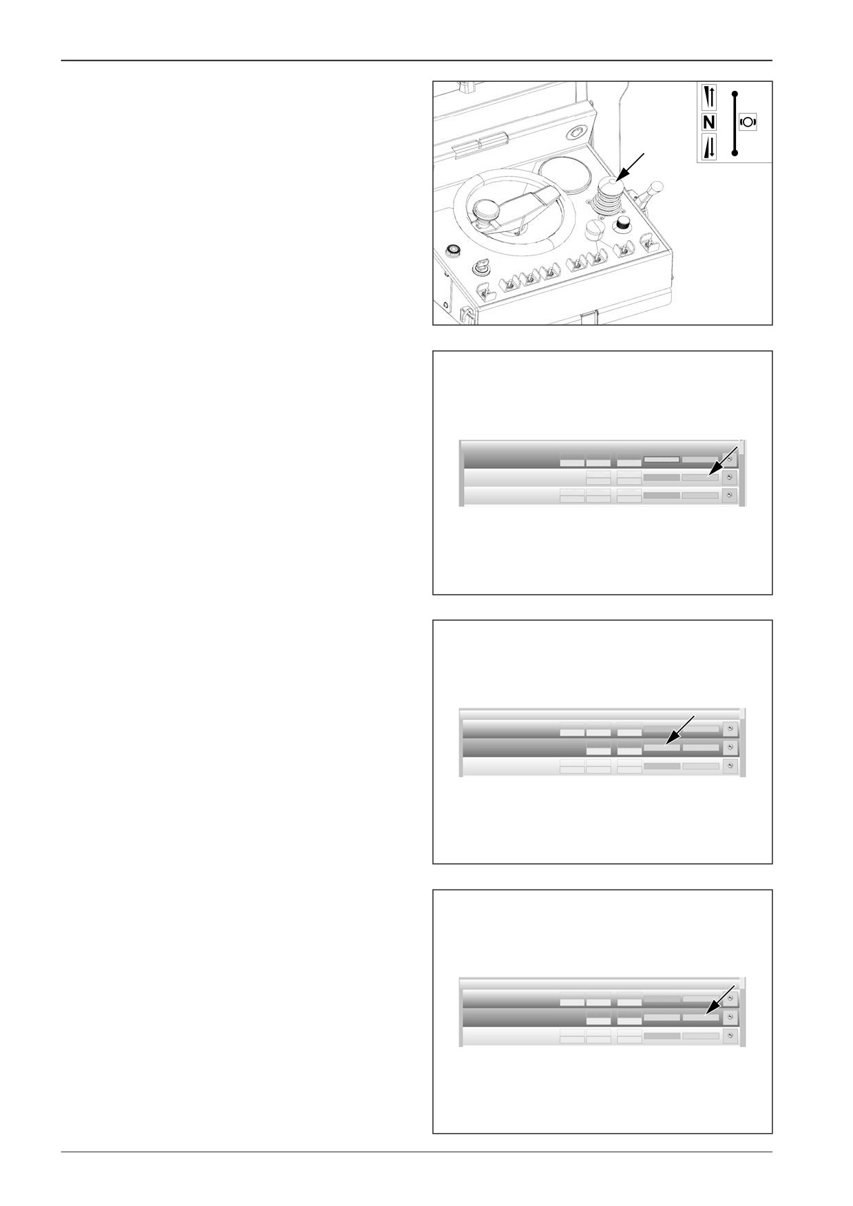
Set the neutral position by the travel controller.
F
0
P
R
451C010
Confirm it by pressing “Adjust”.
The current value will be saved.
1.8 Calibration operation
1.8.1 driving lever
Minimum
Maximum
Current
Set max value
Cancel
0.57V
3.97V
4.12V
STD
Saved
Current
Accept
1.8.2 driving lever middle
2.20V
- - -
Adjust
STD
1.8.3 speed poti
Minimum
Maximum
Current
Accept
Calibrate
0.62V
4.20V
- - -
STD
D451C014
Confirm it by pressing “Accept”.
The red highlighting means that the value has been changed.
1.8 Calibration operation
1.8.1 driving lever
Minimum
Maximum
Current
Accept
Calibrate
0.61V
4.09V
- - -
STD
Saved
Current
1.8.2 driving lever middle
Accept
Cancel
2.24V
2.24V
STD
Minimum
Maximum
Current
1.8.3 speed poti
Accept
Calibrate
0.05V
4.98V
- - -
STD
451C015
After setting the value press “Cancel”.
1.8 Calibration operation
1.8.1 driving lever
Minimum
Maximum
Current
Accept
Calibrate
0.61V
4.09V
- - -
STD
Saved
Current
1.8.2 driving lever middle
Accept
Cancel
2.24V
2.24V
STD
1.8.3 speed poti
Minimum
Maximum
Current
0.05V
4.98V
- - -
Accept
Calibrate
STD
D451C016
204
F80W
WORKSHOP MANUAL
Calibrate the paving speed selector by pressing the “Calibrate”
button.
1.8 Calibration operation
1.8.1 driving lever
Minimum
Maximum
Current
Accept
Calibrate
0.61V
4.09V
- - -
STD
1.8.2 driving lever middle
Saved
Current
Accept
Adjust
2.24V
2.24V
STD
Minimum Maximum
Current
Accept
Calibrate
1.8.3 speed poti
0.05V
4.98V
- - -
STD
D451C017
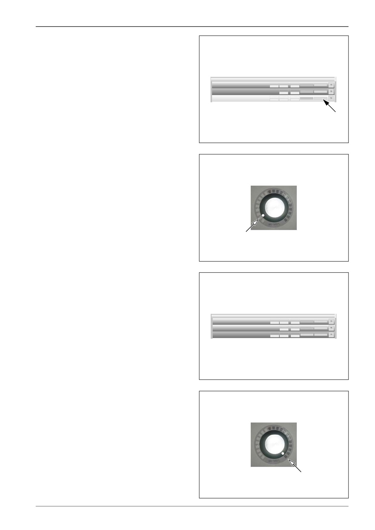
Set the paving speed selector to the min. position.
451C018
Confirm it by pressing the “Set min value” button.
The red highlighting means that the value has been changed.
1.8 Calibration operation
1.8.1 driving lever
Minimum Maximum
Current
Accept
Calibrate
0.61V
4.09V
- - -
STD
1.8.2 driving lever middle
Saved
Current
Accept
Adjust
2.25V
- - -
STD
Minimum Maximum
Current
Set min value
Cancel
1.8.3 speed poti
0.55V
4.98V
0.55 V
STD
D451C019
Set the paving speed selector to the max. position.
451C020
F80W
205
15
Wiring
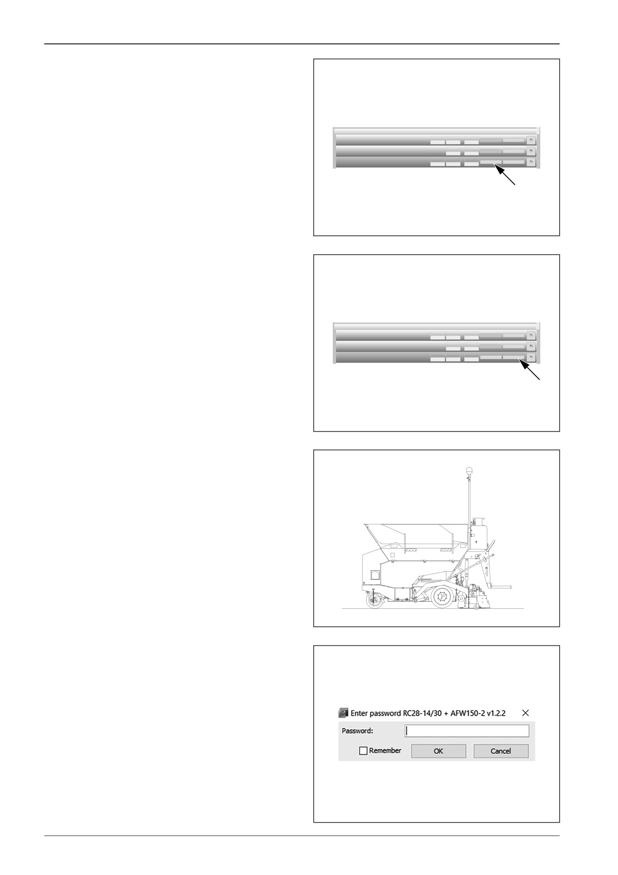
Confirm it by pressing the “Set max value” button.
1.8 Calibration operation
1.8.1 driving lever
Minimum Maximum
Current
Accept
Calibrate
0.61V
4.09V
- - -
STD
1.8.2 driving lever middle
Saved
Current
Accept
Adjust
2.25V
- - -
STD
Minimum Maximum
Current
Set max value
Cancel
1.8.3 speed poti
0.55V
4.28V
4.29 V
STD
D451C021
After setting both values press “Cancel” to end the calibration.
1.8 Calibration operation
1.8.1 driving lever
Minimum Maximum
Current
Accept
Calibrate
0.61V
4.09V
- - -
STD
1.8.2 driving lever middle
Saved
Current
Accept
Adjust
2.25V
- - -
STD
Minimum Maximum
Current
Set max value
Cancel
1.8.3 speed poti
0.55V
4.28V
4.29 V
STD
D451C022
15.3.3
Travel pump calibration
Place the machine onto a flat, firm surface.
With the motor running, heat up the hydraulic oil to the tem-
perature of 40°C.
451C003
Before starting calibration, enter the password.
Note
To obtain the password to the Bodas - service 3.5 system, con-
tact your dealer or the DYNAPAC Technical Support.
D451C023
206
F80W
WORKSHOP MANUAL
A new connection will be uploaded.
D451C024
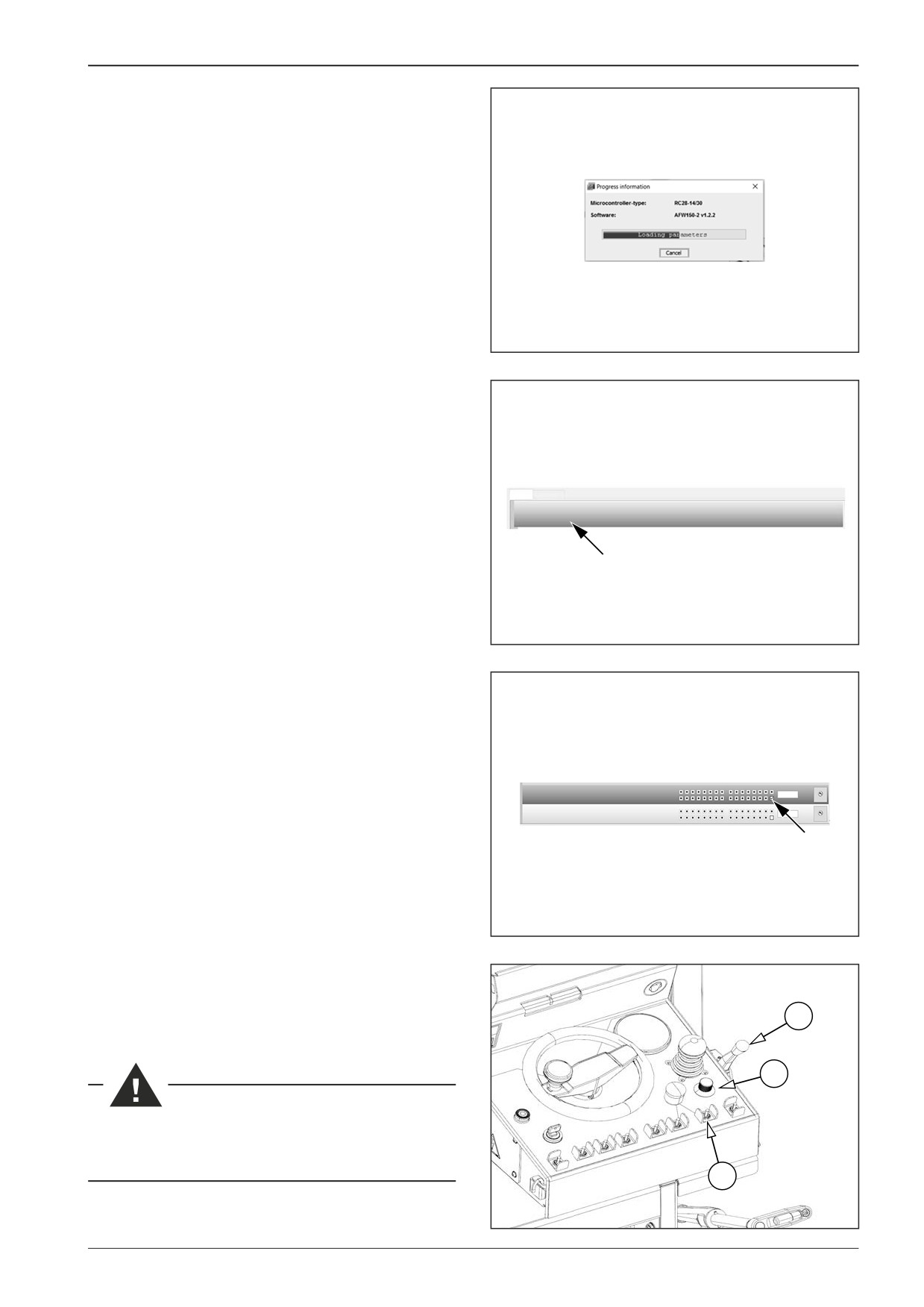
Unroll the “Parameter” tab and select “1.7 Calibration drive”.
Parameter Learning curves
1.6 Brake
1.7 Calibration drive
451C025
Check the last box in “1.7.7 Propel pump calib”. The line will be-
come red and the value will be changed to “1”.
1.7.7 Propel pump calib
1
STD
1.7.8 Set value
0
STD
D451C026
Start the transport speed by the selector switch (15).
Set the paving speed selector (14) to the “min” position.
Adjust maximum engine rpm via controller (10)
10
14
No one is allowed in the hazardous area of the machine
during travel pump calibration.
15
451C027
F80W
207
15
Wiring
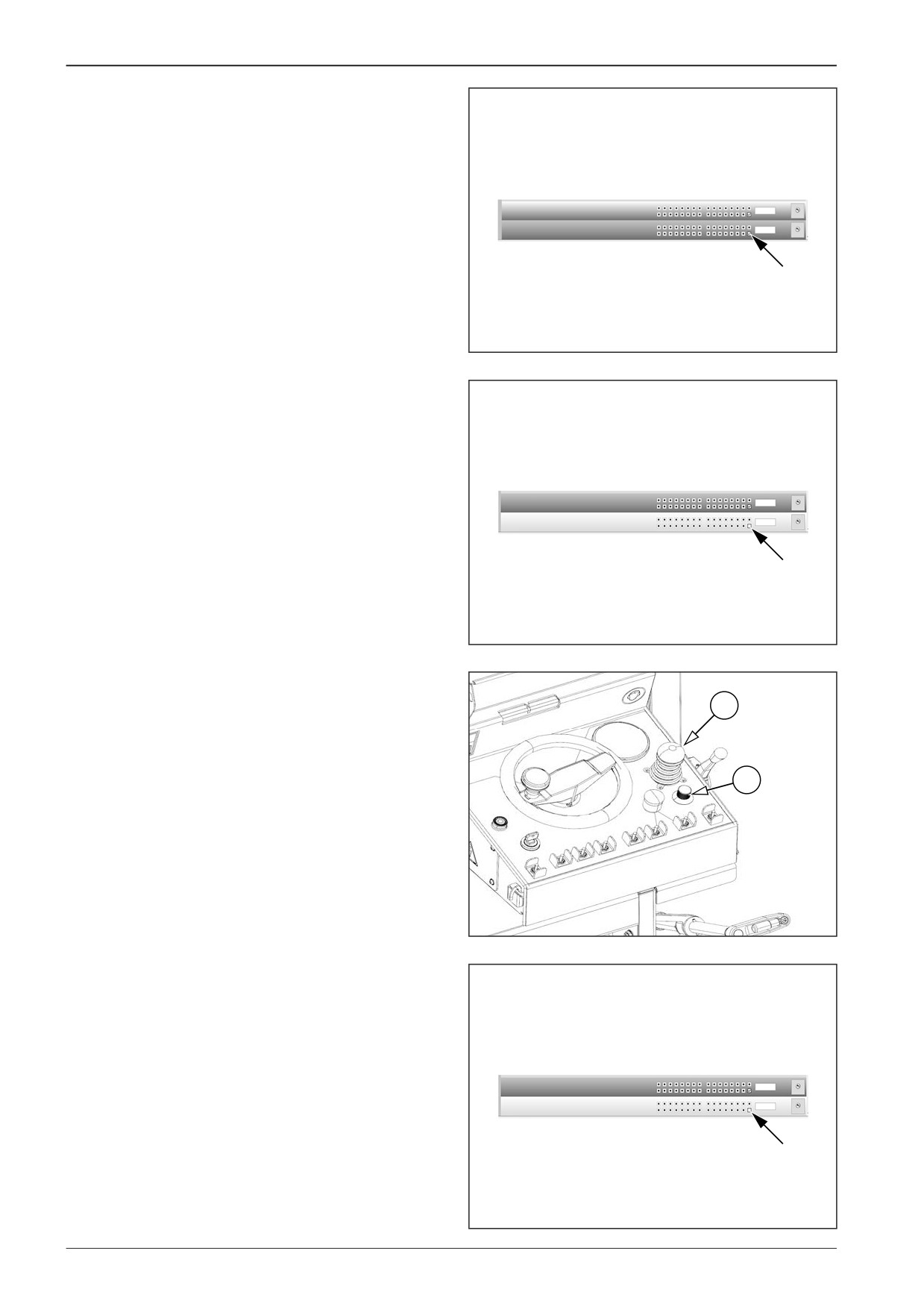
Check the last box in “1.7.8 Set value”. The line will become red
and the value will be changed to “1”.
1.7.7 Propel pump calib
1
STD
1.7.8 Set value
1
STD
D451C028
Uncheck the last box in “1.7.8 Set value”.
A short sound signal will be heard in case of correct setting.
1.7.7 Propel pump calib
1
STD
1.7.8 Set value
0
STD
D451C029
Shift the drive control (8) to the forward travel position.
Slowly turn the paving speed selector (14) so that the machine
8
drives at the lowest possible speed (the wheels are permanently
turning).
14
451C030
Confirm the setting by checking and subsequent unchecking
the box in “1.7.8 Set value”.
A short sound signal is heard.
1.7.7 Propel pump calib
1
STD
1.7.8 Set value
0
STD
D451C029
208
F80W
WORKSHOP MANUAL
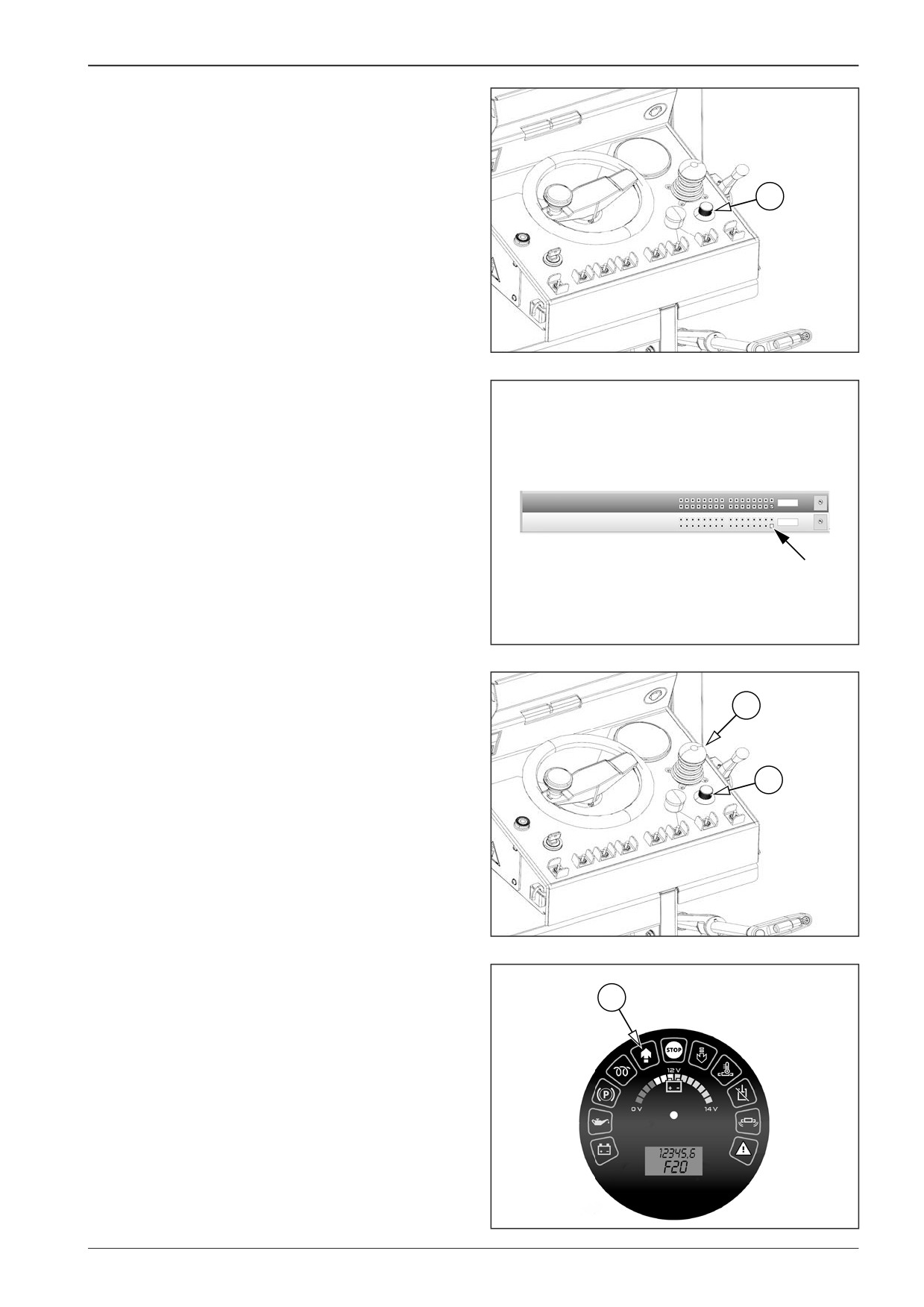
Slowly turn the paving speed selector (14) to the “max” position.
14
451C031
Confirm the setting by checking and subsequent unchecking
the box in “1.7.8 Set value”.
A short sound signal is heard.
1.7.7 Propel pump calib
1
STD
1.7.8 Set value
0
STD
D451C029
Turn the paving speed selector (14) to the “min” position and
wait for the LED indicator (25) to turn off.
8
Then shift the travel controller (8) to the neutral position.
14
451C030
25
D451C032
F80W
209