Dynapac Asphalt paver wheeled F80W Hatz. WORKSHOP MANUAL (2019) - page 4
13
Screed gas heating
Potential faults:
1
Problem in electrical wiring
•
Proceed according to Chapters:
--
Coil electromagnet resistance measurement (13.8.2)
--
Gas supply valve coil power supply measurement
(13.8.3)
--
Spark plug check procedure (13.11.2)
--
Temperature sensor (13.12)
--
High-voltage cables (13.10)
--
Measuring resistance on the ignition unit (13.9.1)
--
Voltage measurement on the cable harness of ignition
units (13.9.2).
2
The flame is not steadily burning
•
Incorrect gas flame adjustment
--
Proceed according to Chapter 13.7.3.
•
Nozzles are clogged.
--
Proceed according to Chapter: 13.7.2.
•
Strainers in the gas supply valves are clogged
--
Proceed according to Chapter: 13.8.1.
•
Faulty gas supply hose
--
Check the supply hoses for damage.
•
Sufficient gas pressure is not available
--
Check the gas quantity in the gas bottle. Replace the gas
bottle for a new one as needed
--
Check that the gas bottle valve and the reducing valve
are opened.
130
F80W
WORKSHOP MANUAL
13.3
Diagnostics
13.3.1
Gas equipment tightness check
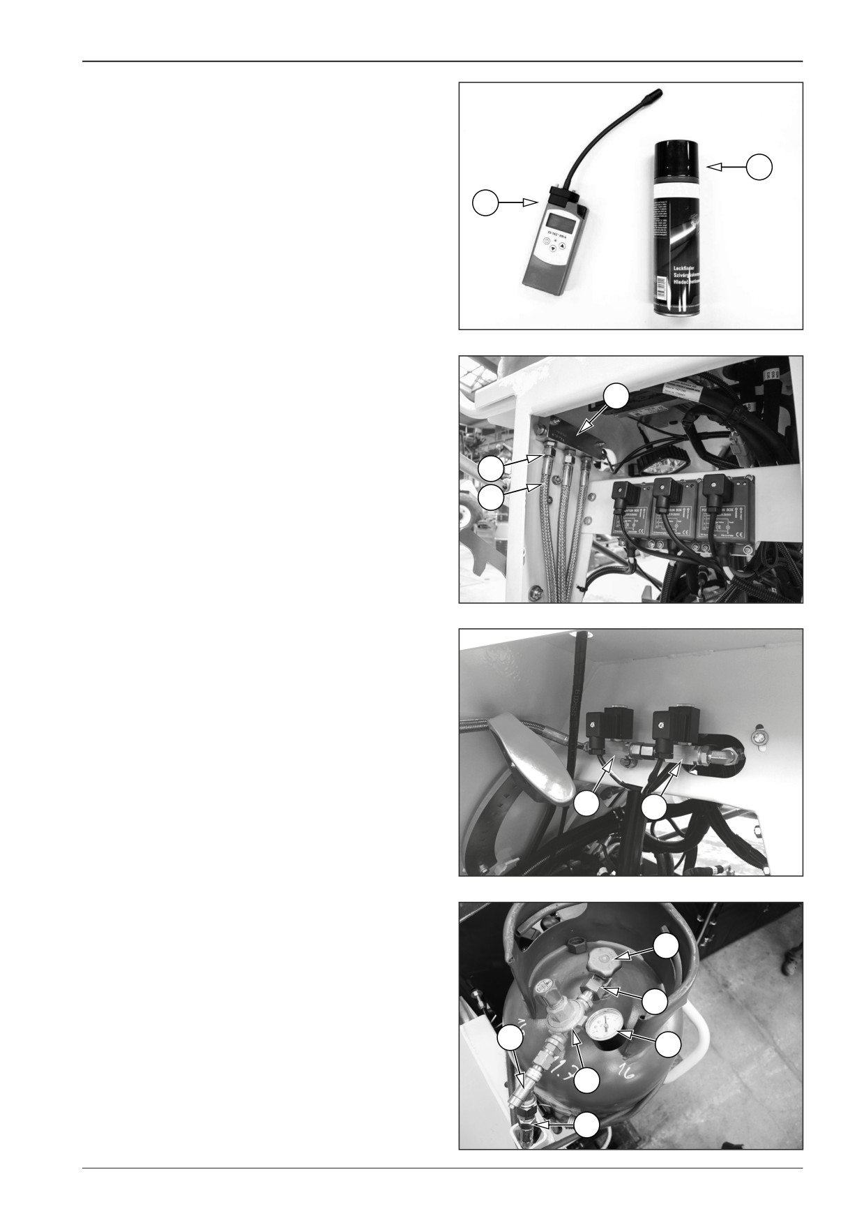
Check the gas equipment for leakage when the machine is
B
parked on a flat and solid surface and the valve (5) of the gas
bottle is open.
A
Measure the gas leak on gas components where there is a dan-
ger of a gas leak.
A gas leak can be detected by means of:
•
a gas leak detector (A)
•
gas leak detection spray (B)
•
soap water.
451610
Gas equipment tightness check procedure
Start the engine.
3
Switch on the screed gas heating.
Check the tightness of the gas equipment, e.g. with a gas leak
detector.
When checking the gas equipment, pay extra attention espe-
2
cially to any damage of hoses and potential gas leaks, and also
check:
1
•
All hoses (1)
•
All fittings (2)
•
Gas supply manifold (3)
D451137A
•
Gas supply solenoid valves (4)
4
4
C451001
•
Gas bottle shut-off valve (5)
•
Tightness of the reducing valve connection to the gas bot-
tle (6)
5
•
Pressure gauge (7)
•
Reducing valve (8)
6
•
Safety valve (9)
•
Tightness of the hose connection to the safety valve (10)
9
7
8
10
D451193B
F80W
131
13
Screed gas heating
•
Tightness of the hose and fitting connection to the burners
(11)
Perform the gas equipment tightness test.
In case of any leak, interrupt the gas supply and have the gas
2
equipment repaired by an authorised service plant or qualified
3
personnel.
Close the gas bottle shut-off valve.
Turn off the screed gas heating.
4
Closed the gas supply.
D
D
Stop the engine.
1
D451198
Do not smoke during machine operation. There is a risk
of explosion or fire. Liquid gas can easily ignite.
The machine must be equipped with a fire extinguisher.
Have the fire extinguisher ready on the driver's stand at
a place intended for this purpose.
Pay extra attention to potential gas leaks and in doubt,
shut off the gas supply.
Check the tightness of the gas equipment, e.g. with a gas
leak detector.
If you detect gas leakage, immediately shut off the gas
bottle shut-off valve and have the gas equipment re-
paired by an authorised service plant or qualified per-
sonnel.
Follow safety regulations for handling gas bottles.
There is a risk of burns. Use protective equipment.
Have the gas equipment tightness check performed by
an authorised service plant or qualified personnel.
132
F80W
WORKSHOP MANUAL
13.4
Reducing valve
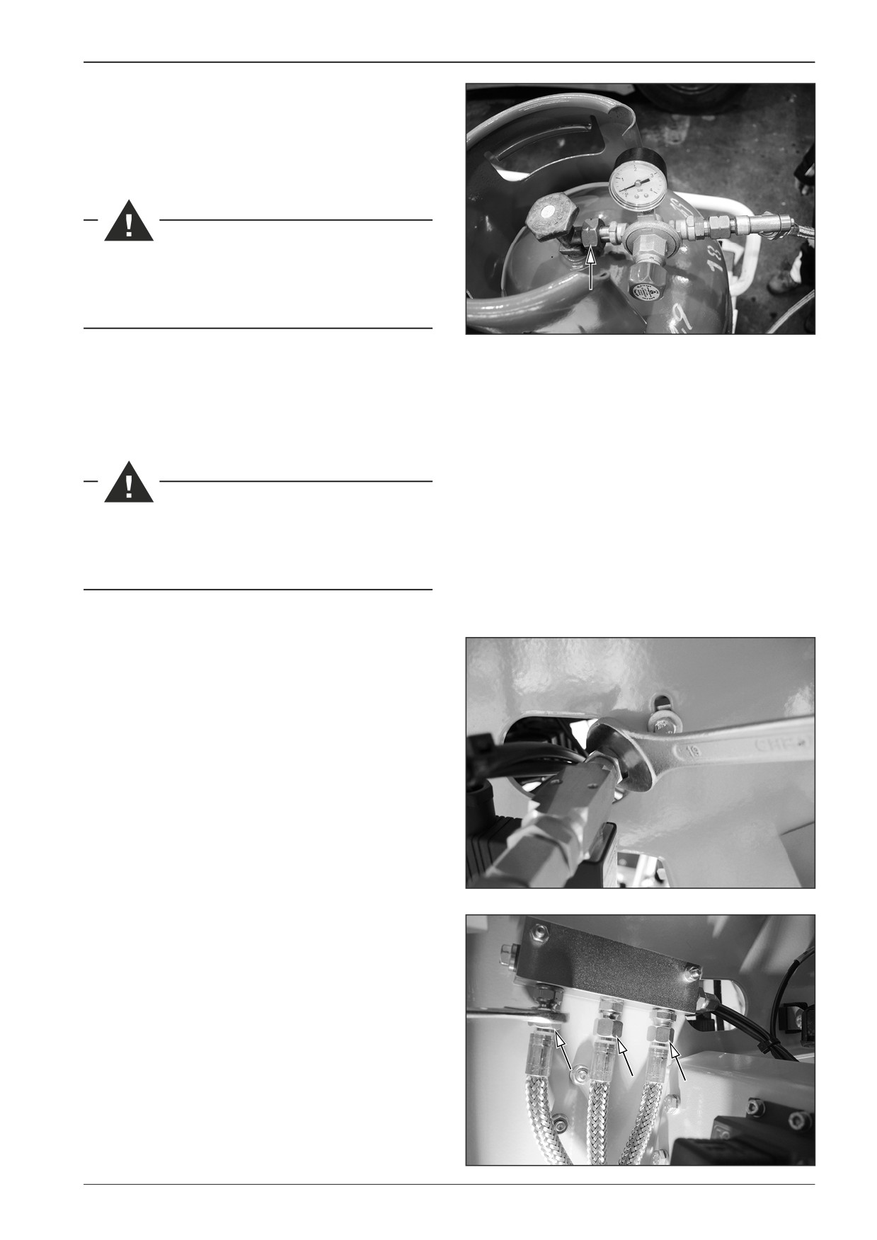
Ensure that individual connections are not loosened and any
gas leak is prevented. The tightening torque on the reducing
valve cap nut must not exceed 3 - 5 Nm (2.2 - 3.7 lbft.)
If the reducing valve replacement is required, perform it
with the machine with the switched off battery discon-
necter and with the closed gas bottle valve.
D451630
13.5
Gas hoses
Ensure that gas hoses are not damaged. In case of their damage,
replace the hoses and perform a gas leakage test.
If the gas hose replacement is required, perform it with
the machine with the switched off battery disconnecter
and with the closed gas bottle valve.
13.6
Gas manifold
13.6.1
Gas manifold replacement
Perform the replacement of the gas manifold with the machine
with the switched off battery disconnecter and with the closed
gas bottle valve.
Remove the gas hoses (4x).
D451611
D451612
F80W
133
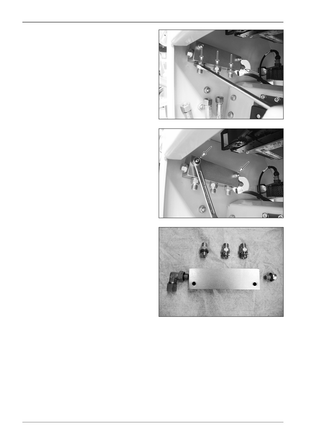
13
Screed gas heating
Loosen the fittings (5x).
D451613
Remove the screws (2x).
D451614
D451615
134
F80W
WORKSHOP MANUAL
13.7
Screed heating burner
13.7.1
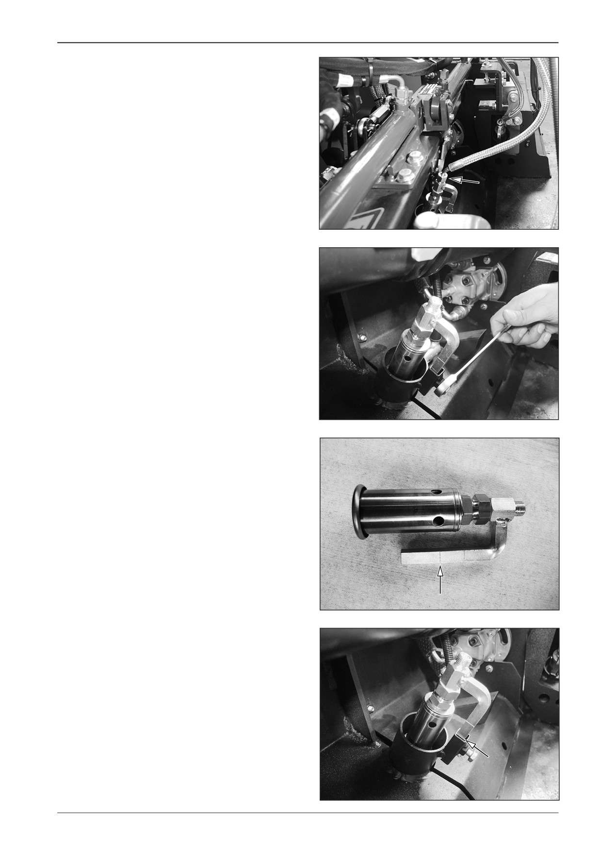
Screed heating burner replacement
Perform the replacement of the screed heating burner with the
machine with the switched off battery disconnecter and with
the closed gas bottle valve.
Remove the hose.
D451596
Loosen the screw and replace the burner.
Note
When reassembling, observe the correct leading of the hose
and prevent its breakage.
D451597
When reassembling, observe the correct location of the burner
lower mark.
D451599
D451600
F80W
135
13
Screed gas heating
13.7.2
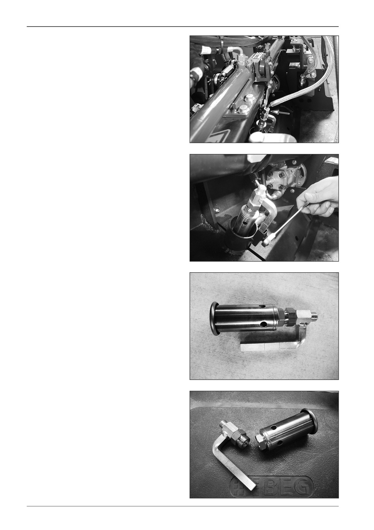
Cleaning the gas burner nozzle
Perform the cleaning of the gas burner nozzle with the machine
with the switched off battery disconnecter and with the closed
gas bottle valve.
Remove the hose.
D451596
Loosen the screw and replace the burner.
D451597
D451598
Remove the burner.
D451601
136
F80W
WORKSHOP MANUAL
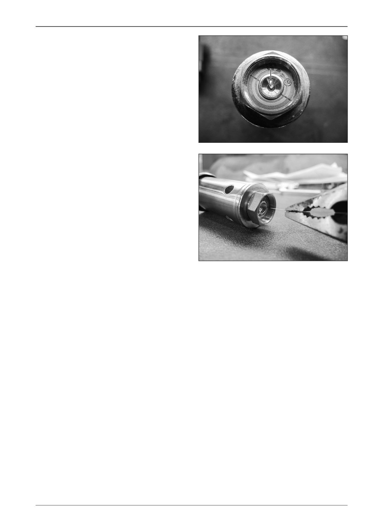
Clean the nozzle hole with a suitable wire.
D451602
D451603
F80W
137
13
Screed gas heating
13.7.3
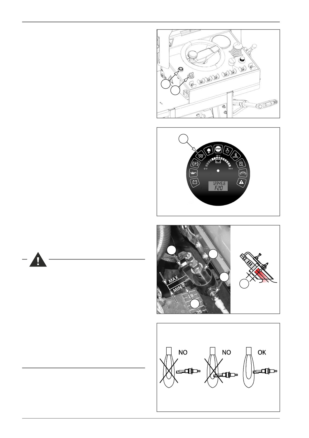
Gas flame adjustment
Open the access to the burners.
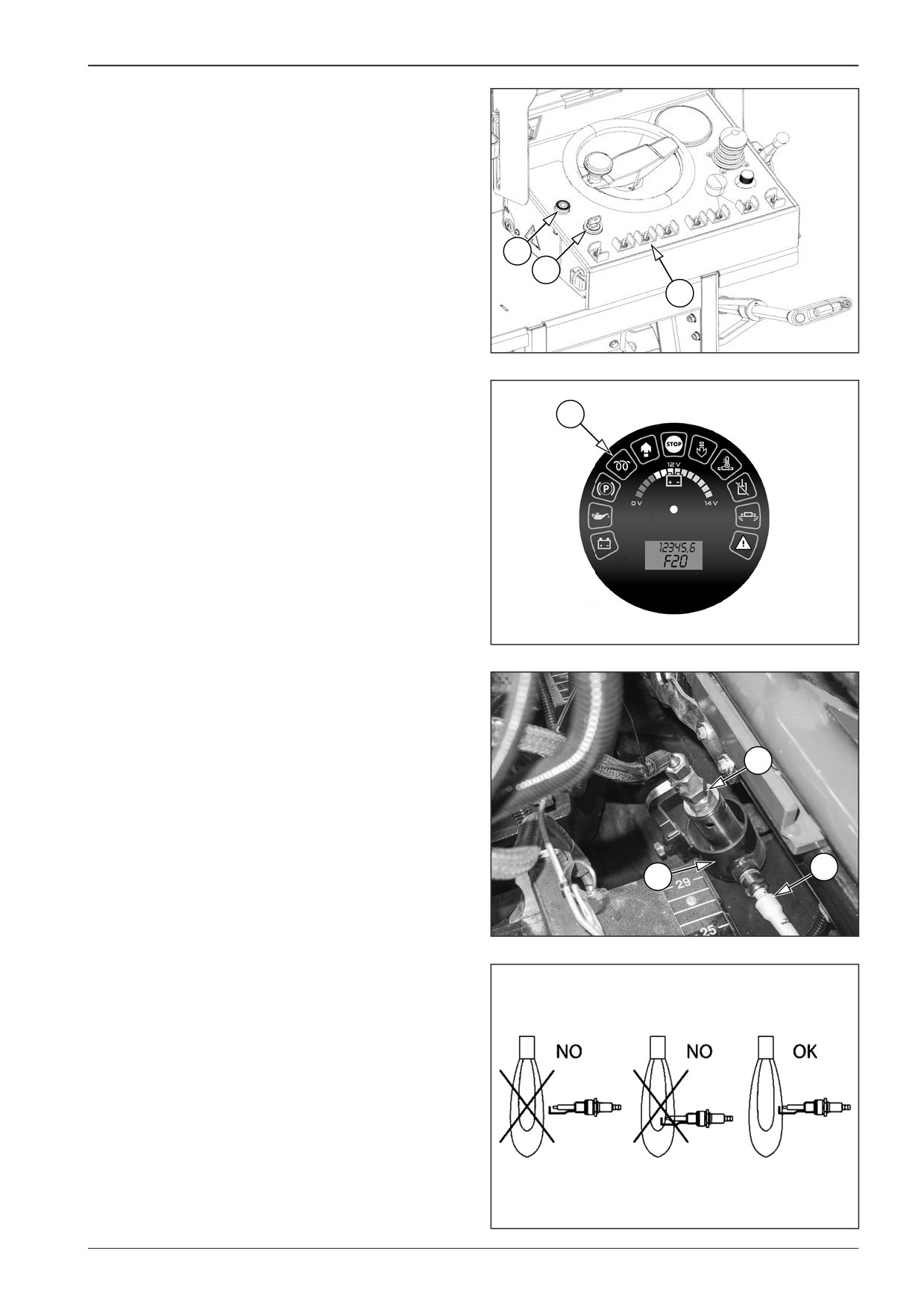
Insert the key into the ignition box (11) in the position “0” and
switch over to the position “I”.
Set the key between position “I” and “II” and the engine glowing
indicator lamp (24) will light up.
Do not perform engine glowing for more than 15 s.
12
Use the alarm horn (12) to signal that the engine is starting.
11
Turn the key to position “II” to start the engine.
Secure the screed against free fall.
Set the maximum paving width on both sides of the machine.
451802A
Turn the key in the ignition box (11) from position “II” to position
“I”. The engine switches off.
Turn the key in the ignition box (11) from position “I” to position
“0” and disconnect the battery disconnecter.
24
Have the correct position of the gas flame adjusted.
Have the flame position adjustment performed by an author-
ised service plant or qualified personnel according to the pro-
cedure given below.
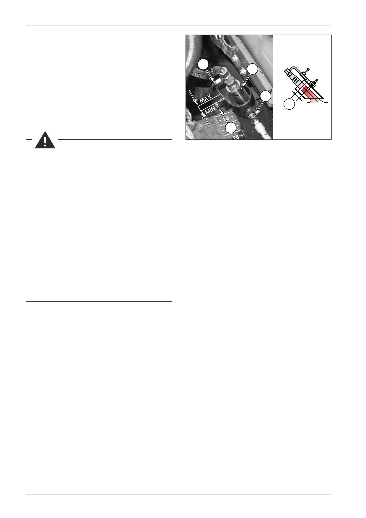
Adjust the distance (D) between the gas burner (3) and the
spark plug (4).
Adjust the distance (D) by loosening the gas burner set screw (1)
on the burner holder (2).
The distance (D) can only be adjusted within the MIN and MAX
marks. The values of MIN and MAX are marked on the burner
holder (2) by marks.
D451064G
After adjusting the burner (3), tighten the burner set screw (1)
on the burner holder (2).
Test the ignition of the burners. In case of incorrect adjustment,
repeat the gas flame adjustment procedure.
2
3
Perform gas flame adjustment when the machine is
4
parked on a flat and solid surface with the engine and
D
battery disconnecter off.
D
Have the gas flame adjustment performed by an author-
ised service plant or qualified personnel according to the
1
given procedure.
D451198
There is a risk of burns. Use protective equipment.
There is a risk of explosion.
Do not smoke during machine operation. There is a risk
of explosion or fire. Liquid gas can easily ignite.
The machine must be equipped with a fire extinguisher.
Have the fire extinguisher ready on the driver's stand at
a place intended for this purpose.
451120
138
F80W
WORKSHOP MANUAL
13.7.4
Test of burner ignition
When testing the burner ignition, check the behaviour of the
burners and the position of the gas flame.
The behaviour of the burners when ignited is correct if the burn-
ers ignite within a few seconds.
Unless the burners ignite within a few seconds, the ignition box
stops further attempts for igniting the burners and interrupts
gas supply.
12
11
Burner ignition test procedure
13
Open the access to the burners.
Insert the key into the ignition box (11) in the position “0” and
451802
switch over to the position “I”.
Set the key between position “I” and “II” and the engine glowing
indicator lamp (24) will light up.
Do not perform engine glowing for more than 15 s.
24
Use the alarm horn (12) to signal that the engine is starting.
Start the engine by turning the key to position “II”.
Secure the screed against free fall.
Set the maximum paving width on both sides of the machine.
Turn the key in the ignition box (11) from position “II” to position
“I”. The engine switches off.
Switch on the gas screed heating system by moving the switch
(13) to the upper position.
Check that all burners are burning.
Unless the burners start within a few seconds, switch off the gas
D451064G
screed heating system and perform a test of spark plugs, or have
spark plug maintenance performed. Have the test and mainte-
nance of spark plugs performed by an authorised service plant
or qualified personnel according to the procedure given below.
Visually check the gas flame position on all burners (1). Perform
the visual check through the burner pipe (2) and check their po-
sition with regard to the spark plug (3).
1
If the gas flame is incorrect, have the flame position adjusted.
Have the flame position adjustment performed by an author-
ised service or qualified personnel according to the procedure
given below.
Switch off the gas screed heating system by moving the switch
3
(13) to the lower position.
2
Close the access to the burners.
Set the key between position “I” and “II” and the engine glowing
D451198B
indicator lamp (24) will light up.
Do not perform engine glowing for more than 15 s.
Use the alarm horn (12) to signal that the engine is starting.
Start the engine by turning the key to position “II”.
Set the minimum paving width on both sides of the machine.
Unlock the screed and lower it to the ground.
Turn the key to the position “0” and remove the key from the
ignition box (11).
451120
F80W
139
13
Screed gas heating
There is a risk of explosion.
Do not smoke during machine operation. There is a risk
of explosion or fire. Liquid gas can easily ignite.
The machine must be equipped with a fire extinguisher.
Have the fire extinguisher ready on the driver's stand at
a place intended for this purpose.
Pay extra attention to potential gas leaks and in doubts,
shut off the gas supply.
Check the tightness of the gas equipment, e.g. with a gas
leak detector.
If you detect gas leakage, immediately shut off the gas
bottle shut-off valve and have the gas equipment re-
paired by an authorised service plant or qualified per-
sonnel.
Follow safety regulations for handling gas bottles.
There is a risk of burns. Use protective equipment.
Have the test and maintenance of spark plugs performed
by an authorised service plant or qualified personnel ac-
cording to the procedure given below.
140
F80W
WORKSHOP MANUAL
13.8
Gas supply solenoid valves
13.8.1
Valve cleanliness inspection
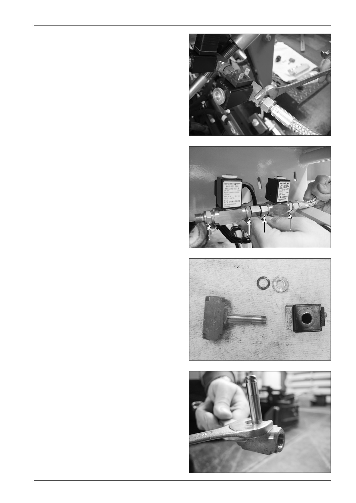
Check the cleanliness of the valves with the machine with the
switched off battery disconnecter and with the closed gas bot-
tle valve.
Remove the fitting.
D451616
D451617
Remove gas supply valves.
D451618
Remove the valve body coil core.
D451619
F80W
141
13
Screed gas heating
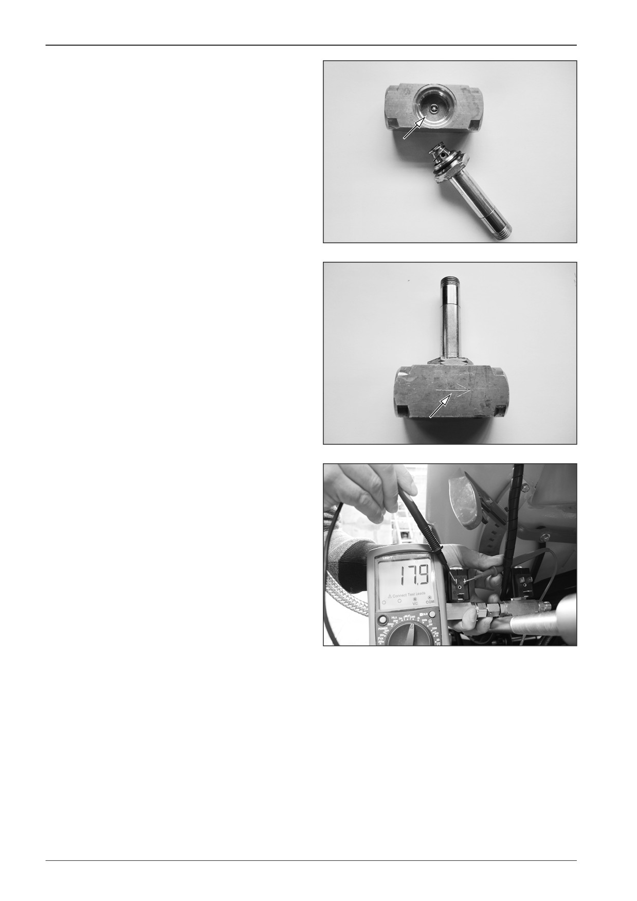
Check that the strainer inside the valve body is not clogged.
D451620
Note
When reassembling, observe the correct placement of the valve
so that the arrow on the valve corresponds to the gas flow direc-
tion.
D451621
13.8.2
Measuring resistance of the coils of gas
supply valve electromagnets
Measure the coil resistance of approximately 18 Ω.
Note
If a different value is measured, replace the coil.
D451622
142
F80W
WORKSHOP MANUAL
13.8.3
Measuring power supply of the coils of
gas supply valve electromagnets
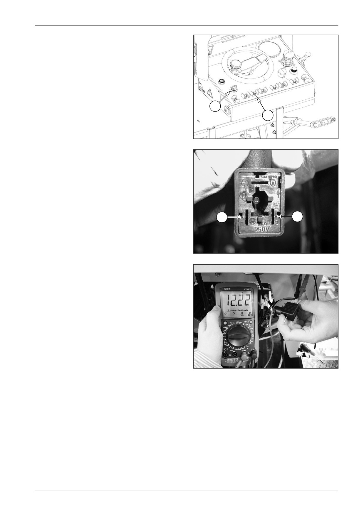
Turn the key in the ignition box (11) to the “I“ position.
Switch on the gas screed heating system by changing over the
switch (13) to the upper position.
11
13
451A802
Measure the battery voltage (12 V) on the sockets of electro-
magnets Y14 and Y15 between pins 1 and 2.
If a different value is measured, check:
•
fuse F6
•
relays K6 and K10
•
wiring between the valve and the units A6, A7 and A8.
1
2
D451623
D451624
F80W
143
13
Screed gas heating
13.9
Ignition units
13.9.1
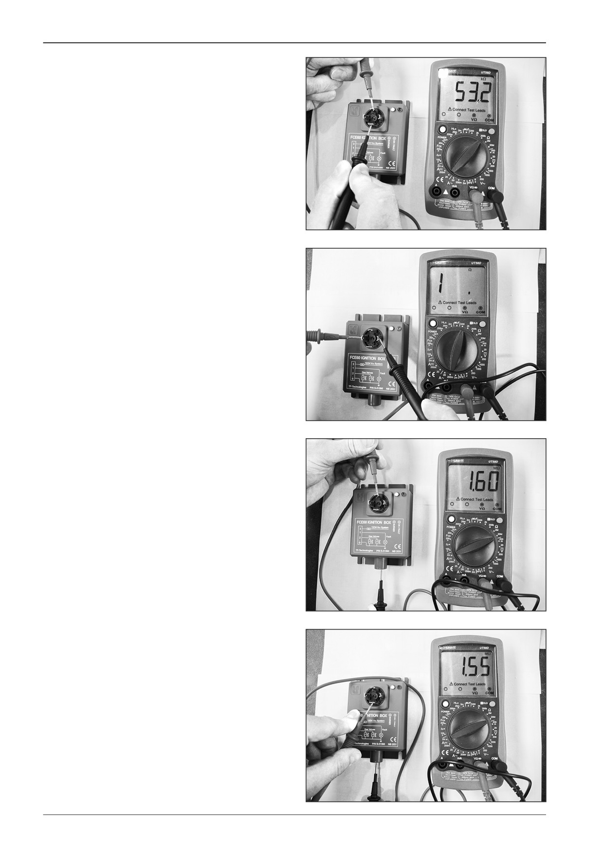
Measuring resistance on the ignition
unit
Measure resistances on the ignition unit on the machine with
the switched off battery disconnecter and with the closed gas
bottle valve.
Measure the resistance on the unit with disconnected supply
cables.
Measure the resistance of approximately 53.2 Ω between pin 3
D451636
and pin of the frame.
There is an opened circuit between pin 3 and pins 1 and 2.
There is an opened circuit between the pin of the frame and
pins 2 and 3.
D451637
Measure the resistance of approximately 1.6 Ω between pin 3
and pin 4.
Note
If a different value is measured, replace the ignition unit.
D451638
Measure approximately 1.55 MΩ between the pin of the frame
and pin 4.
Note
If a different value is measured, replace the ignition unit.
D451639
144
F80W
WORKSHOP MANUAL
13.9.2
Voltage measurement on the cable
harness of ignition units
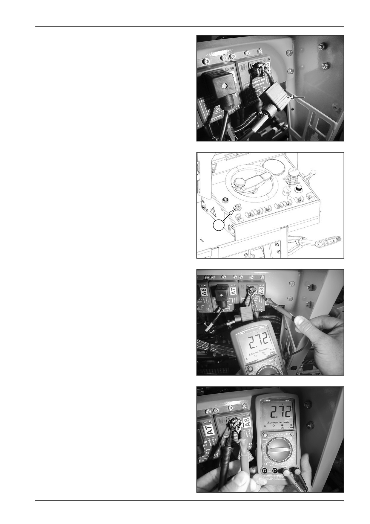
Measure the voltage on the cable harness of ignition units on
the machine with the closed gas bottle valve.
Remove the cover of connector X73, X74 or X75.
D451640
Turn the key in the ignition box (11) to the “I“ position.
11
451641
Measure the voltage of approximately 2.72 V between the pin of
the frame and pin 1.
Note
If a different value is measured, check:
•
the wiring between ignition units A6, A7, A8 and the control
unit A2
•
the wiring between the pin of the frame on connector X73,
X74 or X75 and the required pin of the central earthing point
X6.
D451642
Measure the voltage of approximately 2.72 V between pin 1 and
pin 2.
Note
If a different value is measured, check:
•
the wiring between ignition units A6, A7, A8 and the control
unit A2
•
the wiring between the pin of the frame on connector X73,
X74 or X75 and the correct pin of the central earthing point
X6.
D451643
F80W
145
13
Screed gas heating
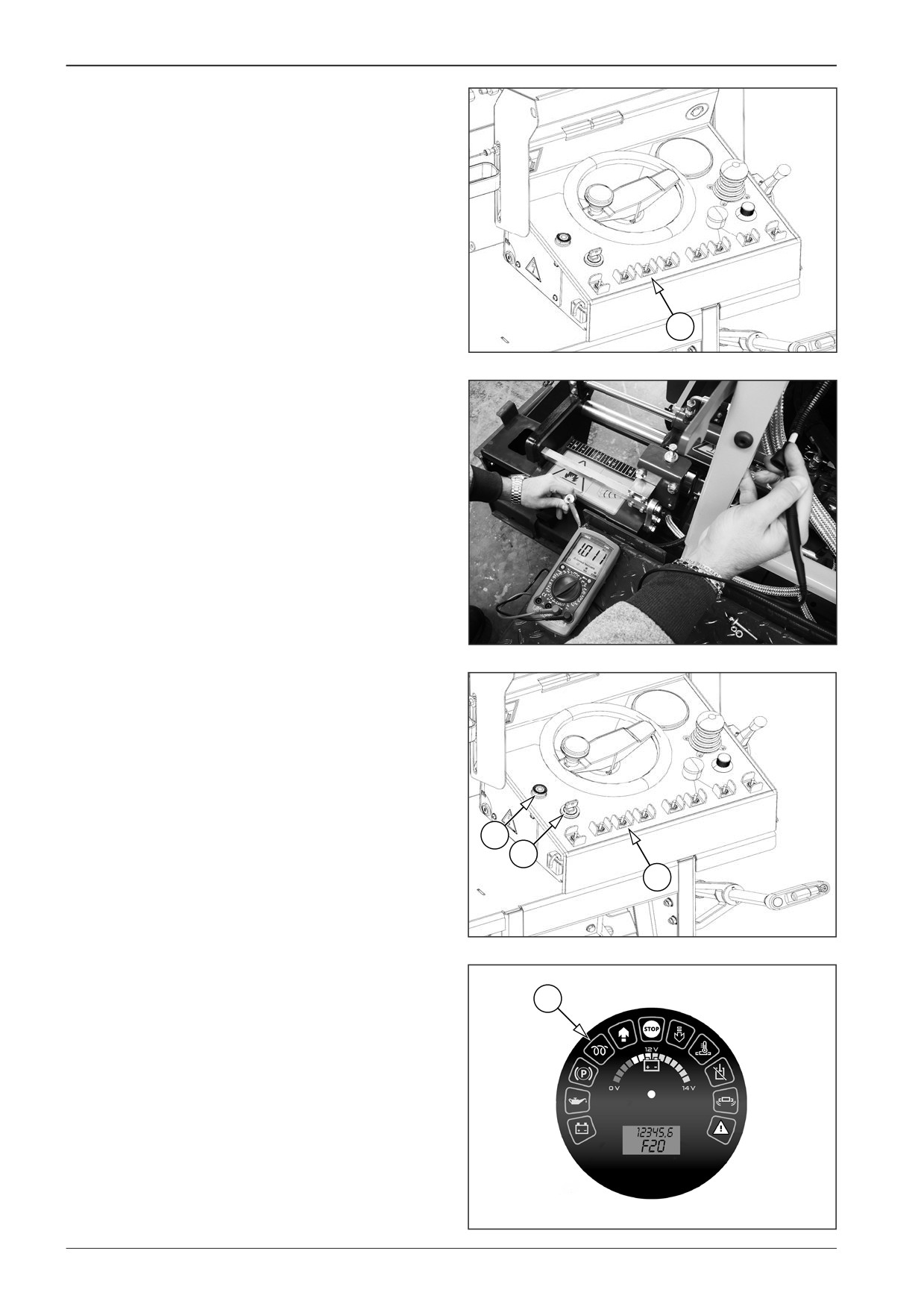
Switch on the gas screed heating system by moving the switch
(13) to the upper position.
Measure the voltage of the battery (12 V) between the pin of the
frame and pins 2 and 3.
13
451644
13.10
High-voltage cables
Measure and replace the high-voltage cables on the machine
with the switched off battery disconnecter and with the closed
gas bottle valve.
Measure the resistance of approximately 1 kΩ.
Note
If a different value is measured, replace the high-voltage cables.
D451625
13.11
Spark plugs
13.11.1Spark plug function test
Insert the key into the ignition box (11) in the position “0” and
switch over to the position “I”.
Set the key between position “I” and “II” and the engine glowing
indicator lamp (24) will light up.
Do not perform engine glowing for more than 15 s.
12
Use the alarm horn (12) to signal that the engine is starting.
11
Turn the key to position “II” to start the engine.
13
Secure the screed against free fall.
Set the maximum paving width on both sides of the machine.
451802
Turn the key in the ignition box (11) from position “II” to position
“I”. The engine switches off.
Close the gas bottle shut-off valve.
24
Switch on the gas screed heating system by moving the switch
(13) to the upper position.
Test the spark plugs for sparking and correct sending of the sig-
nal pulse.
Switch off the gas screed heating system by moving the switch
(13) to the lower position.
Turn the key to the “0” position.
Disconnect the battery disconnecter.
D451064G
146
F80W
WORKSHOP MANUAL
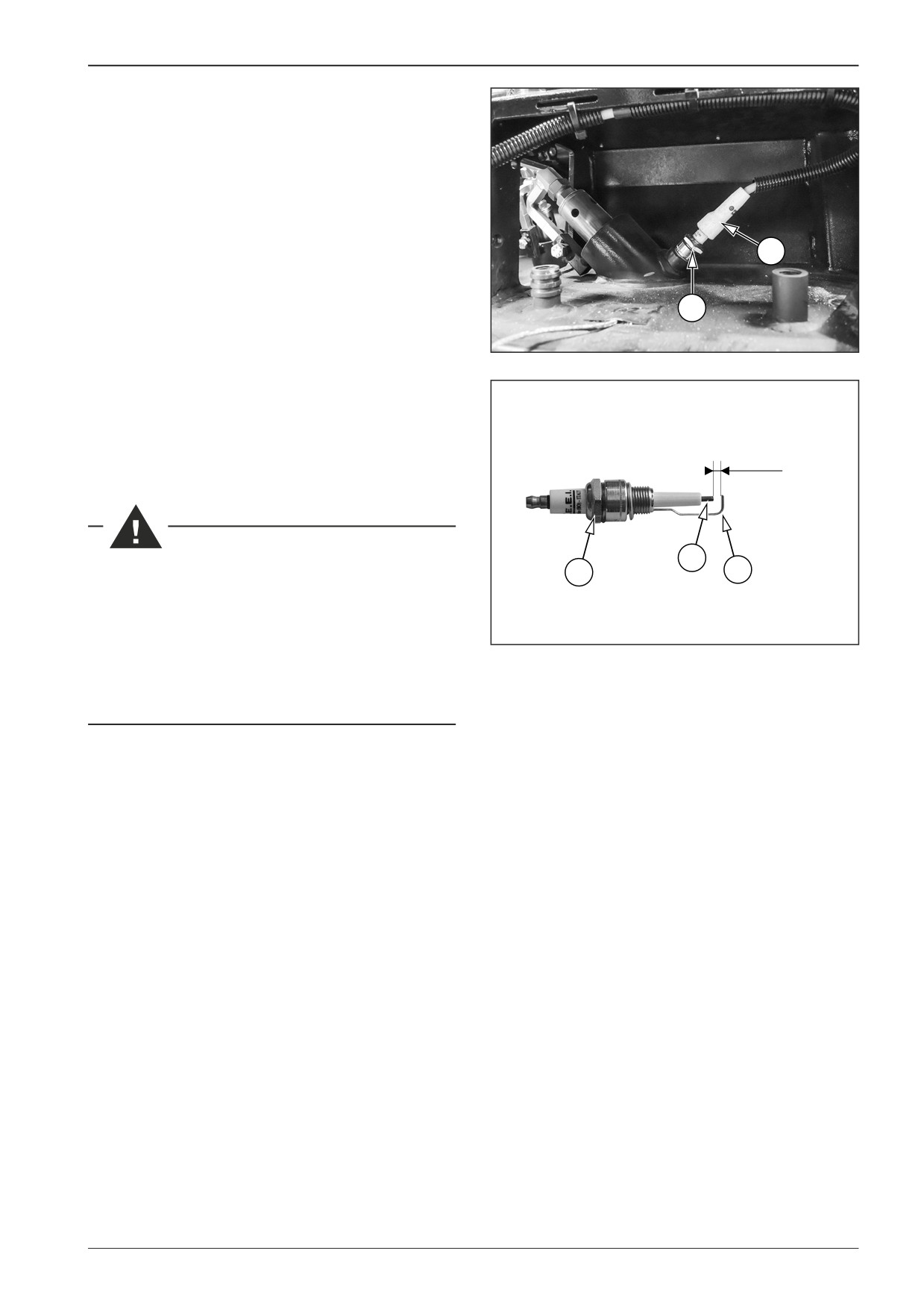
13.11.2Spark plug check procedure
Dismount the cable (4) of a spark plug (3).
Dismount the spark plug (3).
Check the middle electrode (5)
If the spark plug is too burned, replace the spark plug (3) for
a new one.
Measure the distance between the middle electrode (5) and
the external electrode (6). The correct distance must be 4 mm
4
(0.2 in).
In case of incorrect distance, adjust the distance between the
3
middle electrode (5) and the external electrode (6) by slightly
bending the external electrode (6).
D451199A
Screw in the spark plug (3).
Mount the cable of the spark plug (4).
Perform the spark plug test again according to the previous pro-
cedure.
Unless the burners start within a few seconds, repeat the whole
procedure.
4 mm (0,2 in)
5
Perform maintenance of spark plugs when the machine
3
6
is parked on a flat and solid surface with the engine and
battery disconnecter off.
Have the test and maintenance of spark plugs performed
D451152
by an authorised service plant or qualified personnel ac-
cording to the given procedure.
There is a risk of burns. Use protective equipment.
F80W
147
13
Screed gas heating
13.12
Temperature sensor
Measure the temperature sensor on the machine with the
closed gas bottle valve.
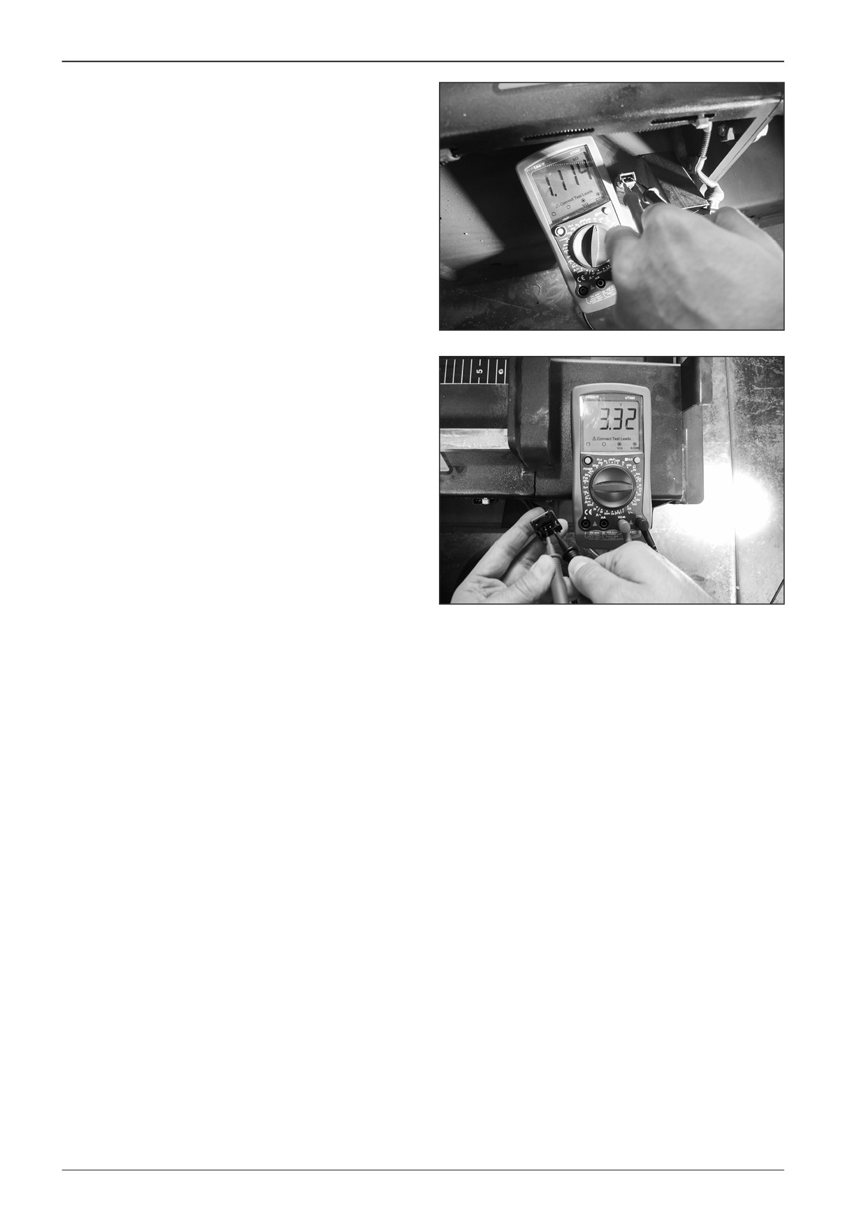
Measure the resistance of approximately 1.1 kΩ at the tempera-
ture of 20°C on the pins of the temperature sensor.
D451645
Measure the voltage of approximately 3.32 V on the pins of the
temperature sensor socket.
Note
If a different voltage value is measured, check the wiring be-
tween the control unit A2 and the sensor S18.
In case of a short circuit or interruption of the cables, the error
message F70 is displayed.
D451646
148
F80W
WORKSHOP MANUAL
14
Belt conveyors and augers
F80W
149
14
Belt conveyors and augers
14.1
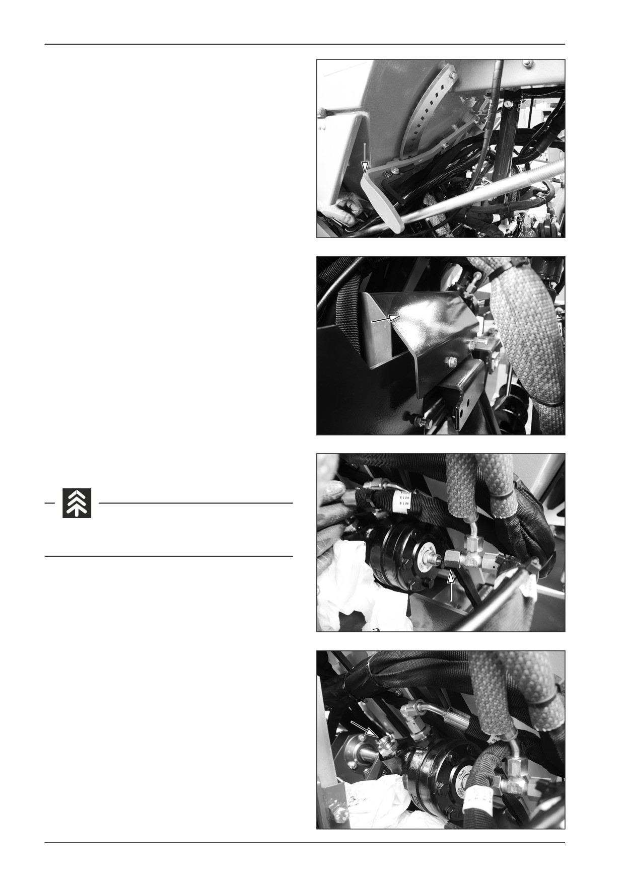
Replacement of the hydraulic motor for
driving the augers and the belt conveyor
Set the lever for material outlet to the lower position.
D421524
Remove the cover of the drive for belt conveyors and augers.
D421525
Remove the hydraulic hoses.
Avoid the oil soaking into the ground.
D421526
D421527
150
F80W
WORKSHOP MANUAL
D421528
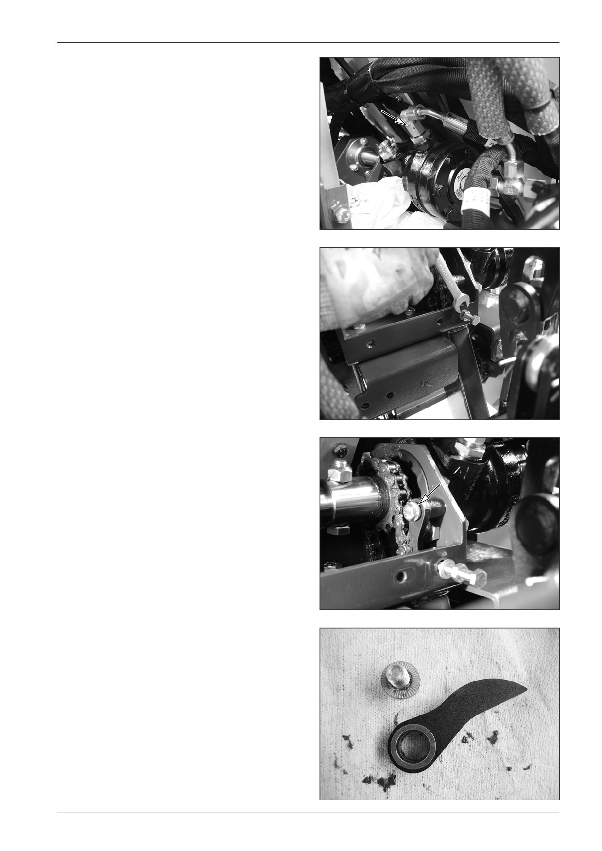
Remove the tension screw.
D421529
Remove the screw for fastening the tension mechanism of the
auger chain.
D421530
D421531
F80W
151
14
Belt conveyors and augers
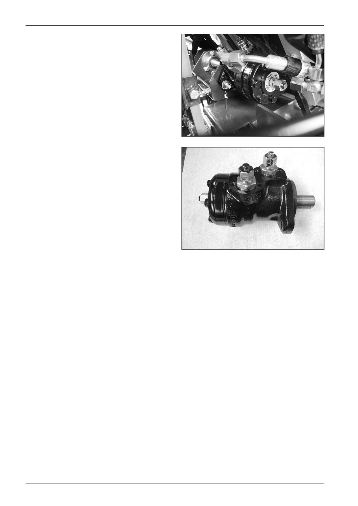
Remove fastening screws of the hydraulic motor (2x).
D421532
Take out the hydraulic motor for driving the belt conveyor and
auger.
Note
When reassembling the hydraulic motor of augers and belt con-
veyors, proceed in the reverse order.
D421533
152
F80W
WORKSHOP MANUAL
14.2
Dismounting the belt conveyor chain
Dismount the belt conveyor chain from the machine with the
switched off battery disconnecter and with the closed gas bot-
tle valve.
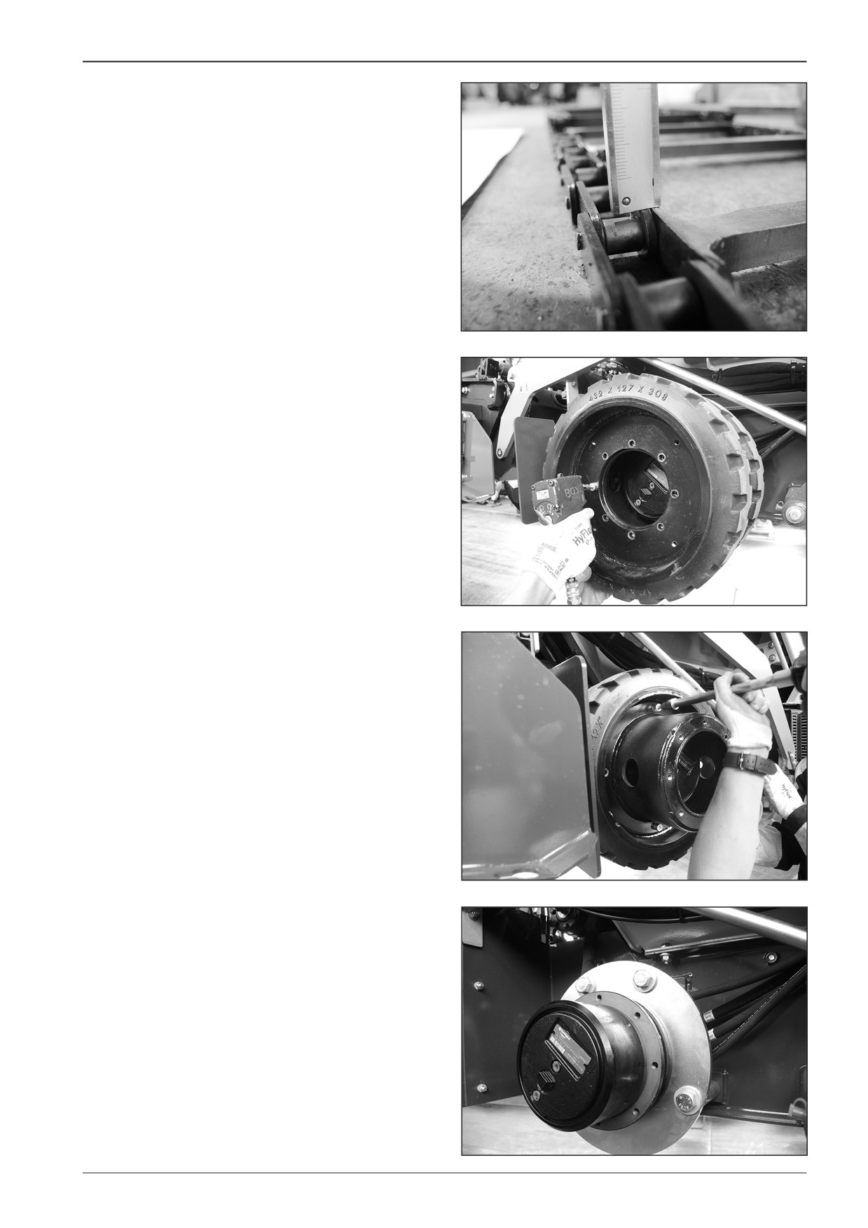
Replace the belt conveyor chain when the thickness between
the chain and the cylinder is 0 mm at the latest.
D451534
Remove the rear wheels on the left side of the machine.
D451517
D451518
D451519
F80W
153
14
Belt conveyors and augers
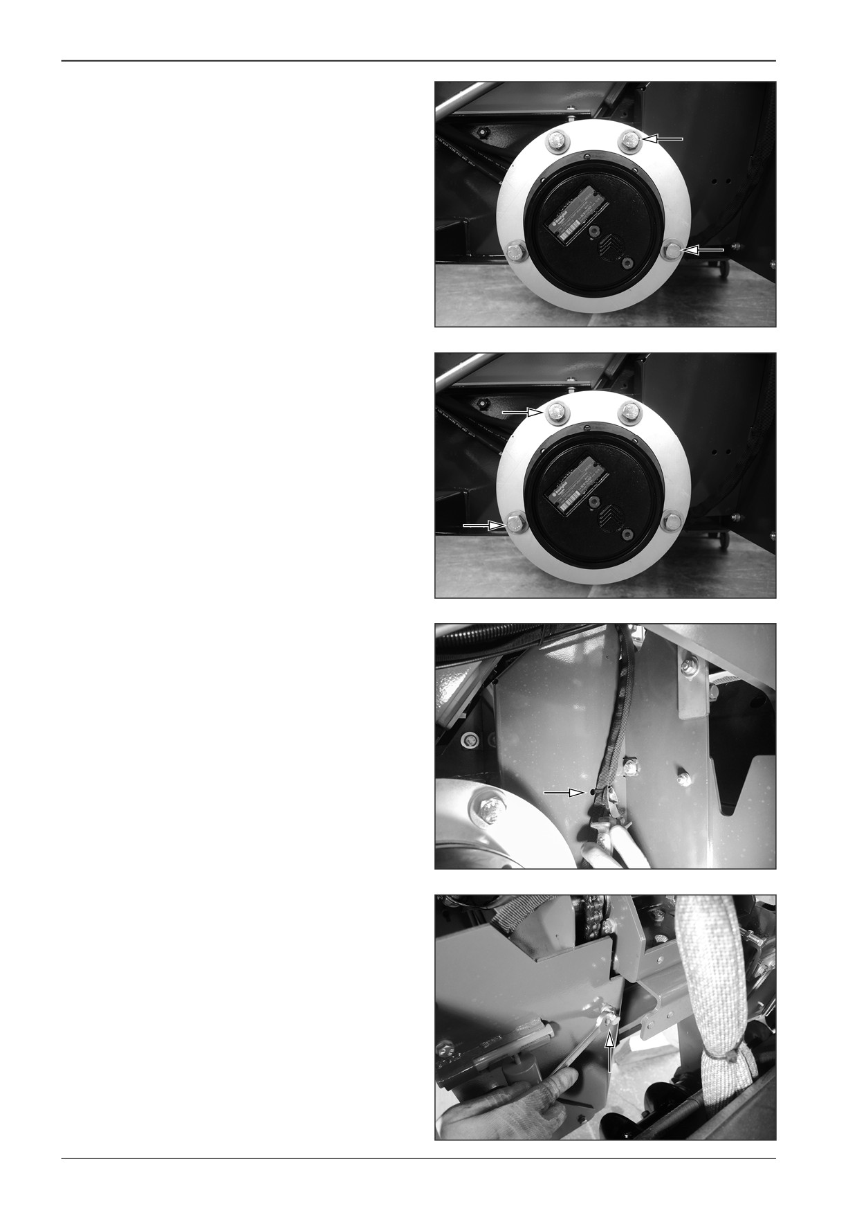
Remove the drive chain of the belt conveyor.
•
Remove the screws of the hydraulic motor (2x).
D451539
•
Loosen the hydraulic motor screws (2x). Pull the hydraulic
motor slightly out towards you.
D451540
•
Cut the binding strap of the hose and remove the cover of
the drive.
D451541
•
Remove the tension screw for the conveyor drive.
D451542
154
F80W
WORKSHOP MANUAL
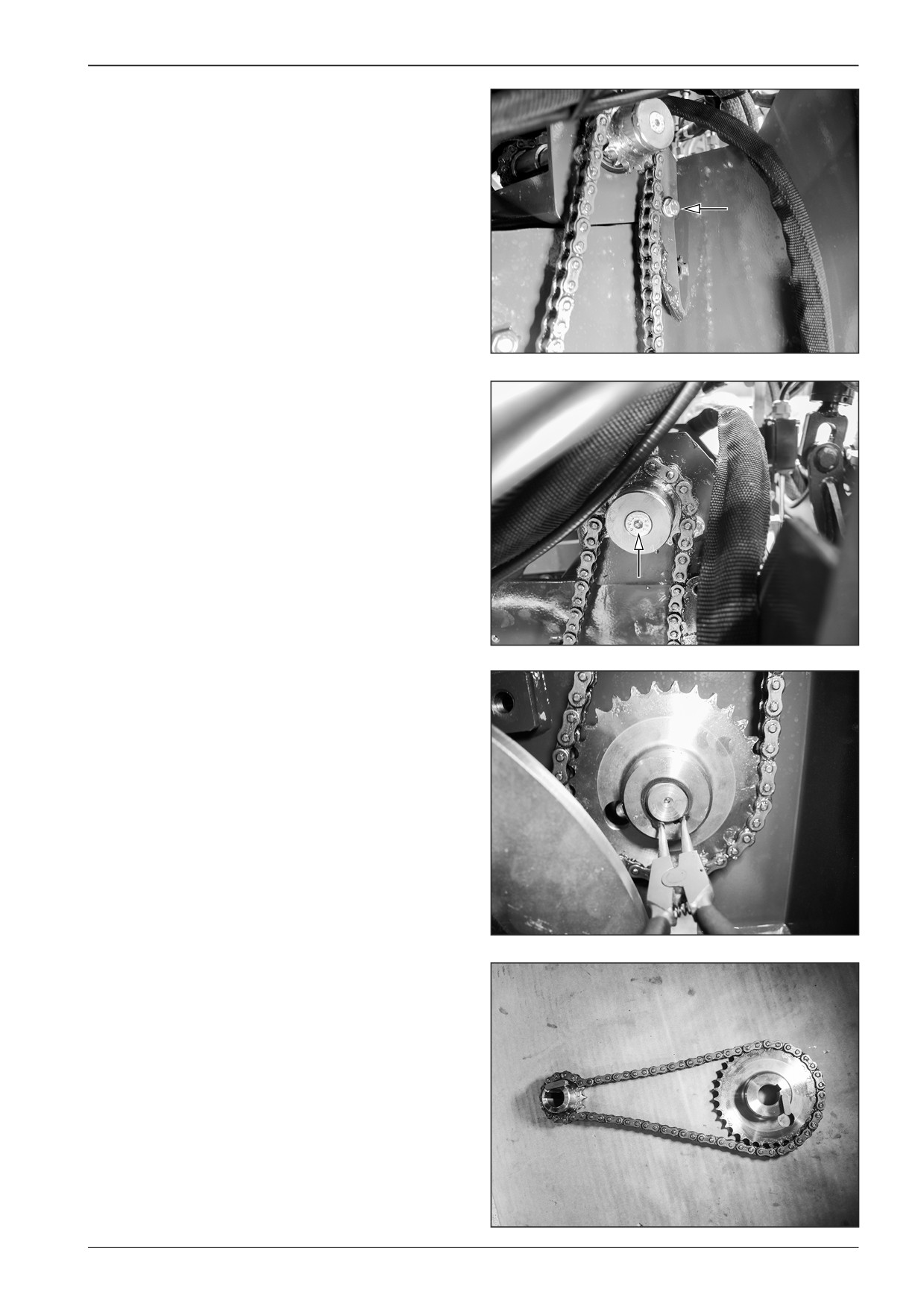
•
Remove the screw.
D451543
•
Remove the screw and the washer.
D451544
•
Remove the lock ring.
D451545
•
Remove the gear wheels.
D451546
F80W
155
14
Belt conveyors and augers
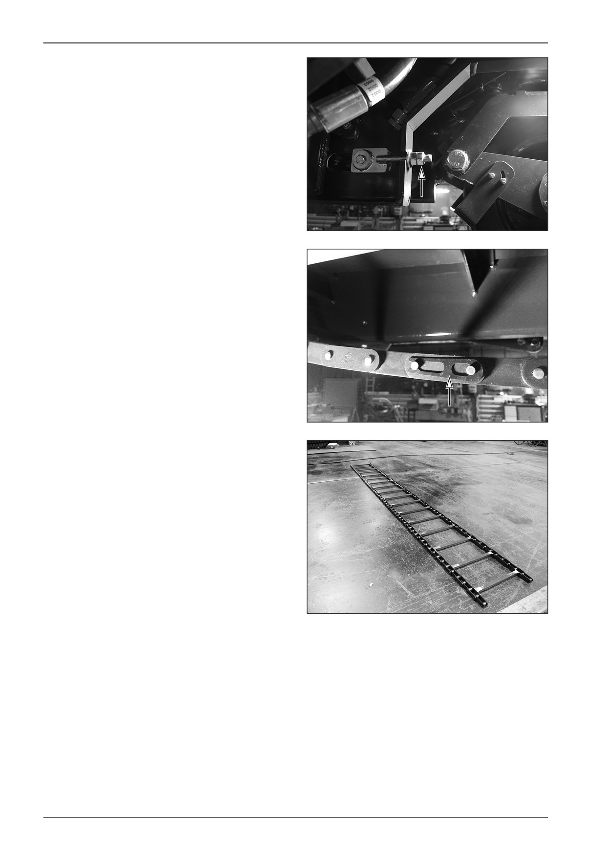
Loosen the tension screws of the belt conveyor on the left and
right side of the machine.
D451535
By moving the belt conveyor find and dismount chain coupling
links (2x).
D451536
Take the chain out of the machine.
D451537
156
F80W
WORKSHOP MANUAL
14.3
Mounting the belt conveyor chain
Mount the belt conveyor chain to the machine with the switched
off battery disconnecter and with the closed gas bottle valve.
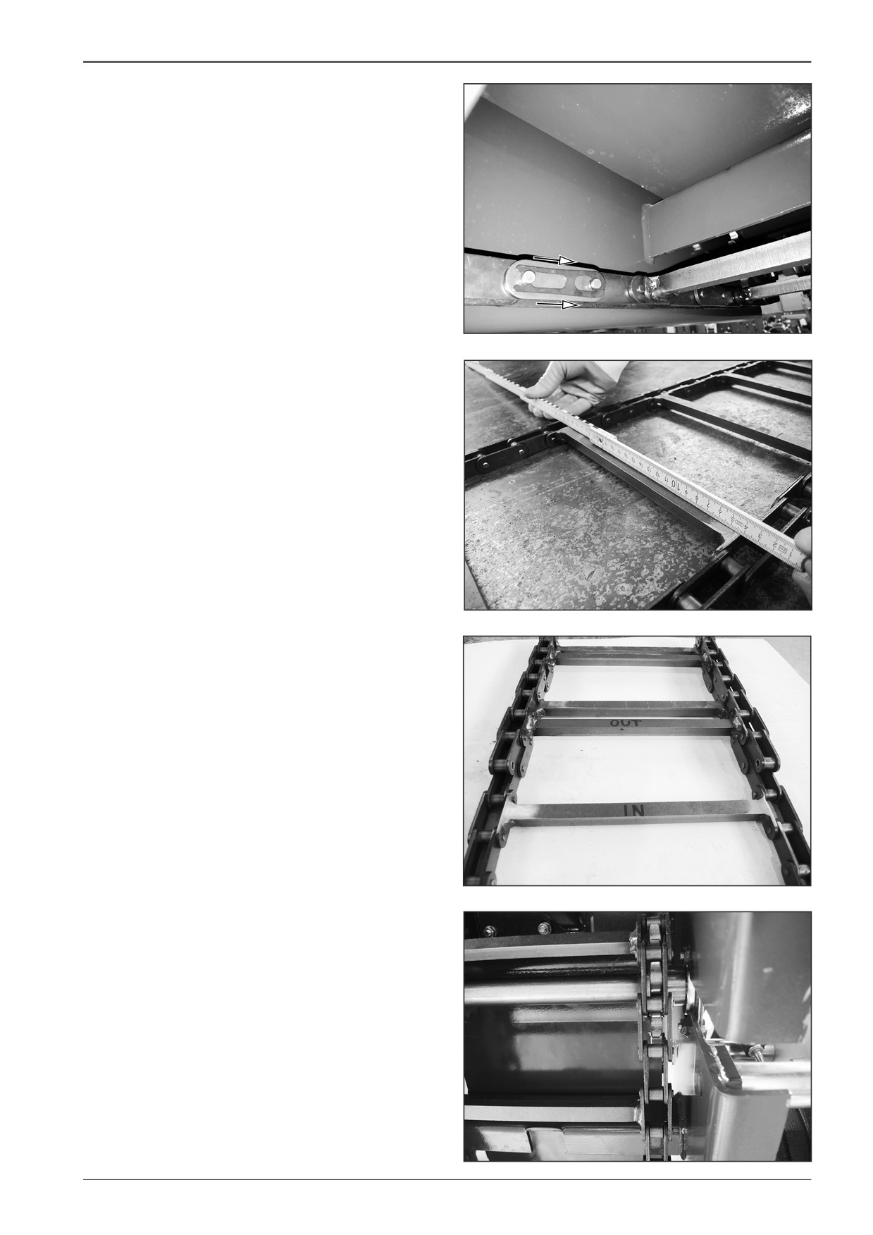
Insert the chain to the machine and mount the chain coupling
links (2x). Secure the chain coupling links in the direction of con-
veyor chain movement from the inner side of the chain.
Note
Ensure that the conveyor chain is installed with the contact sur-
face to the chain guide plate.
DD451038
451567
D451568
Ensure that the chain is at the same distance from the machine
frame on both sides.
D451569
F80W
157
14
Belt conveyors and augers
Tighten the tension screws on the left and right side of the ma-
chine. Test the correct running of the chain by manually turning
the chain of the belt conveyor.
Observe the correct conveyor chain tension according to Chap-
ter 14.4.
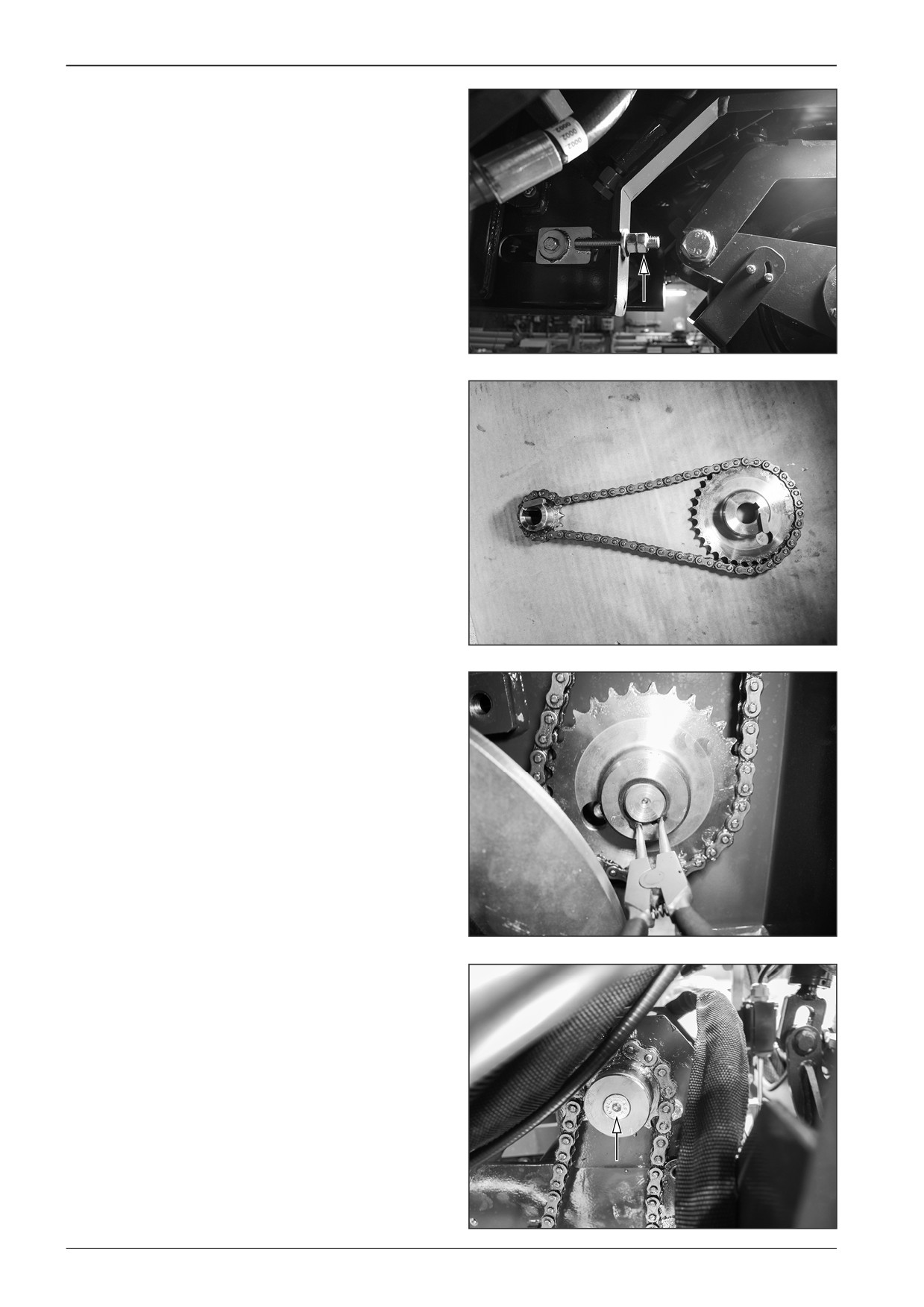
Mount the belt conveyor drive chain by proceeding in the re-
verse order according to Chapter 14.5.
D451535
Mount the drive chain of the belt conveyor.
•
Mount the gear wheels with the chain for driving the belt
conveyor.
D451546
•
Mount the lock ring.
D451545
•
Mount the screw and the washer.
D451544
158
F80W
WORKSHOP MANUAL
•
Mount the screw.
D451543
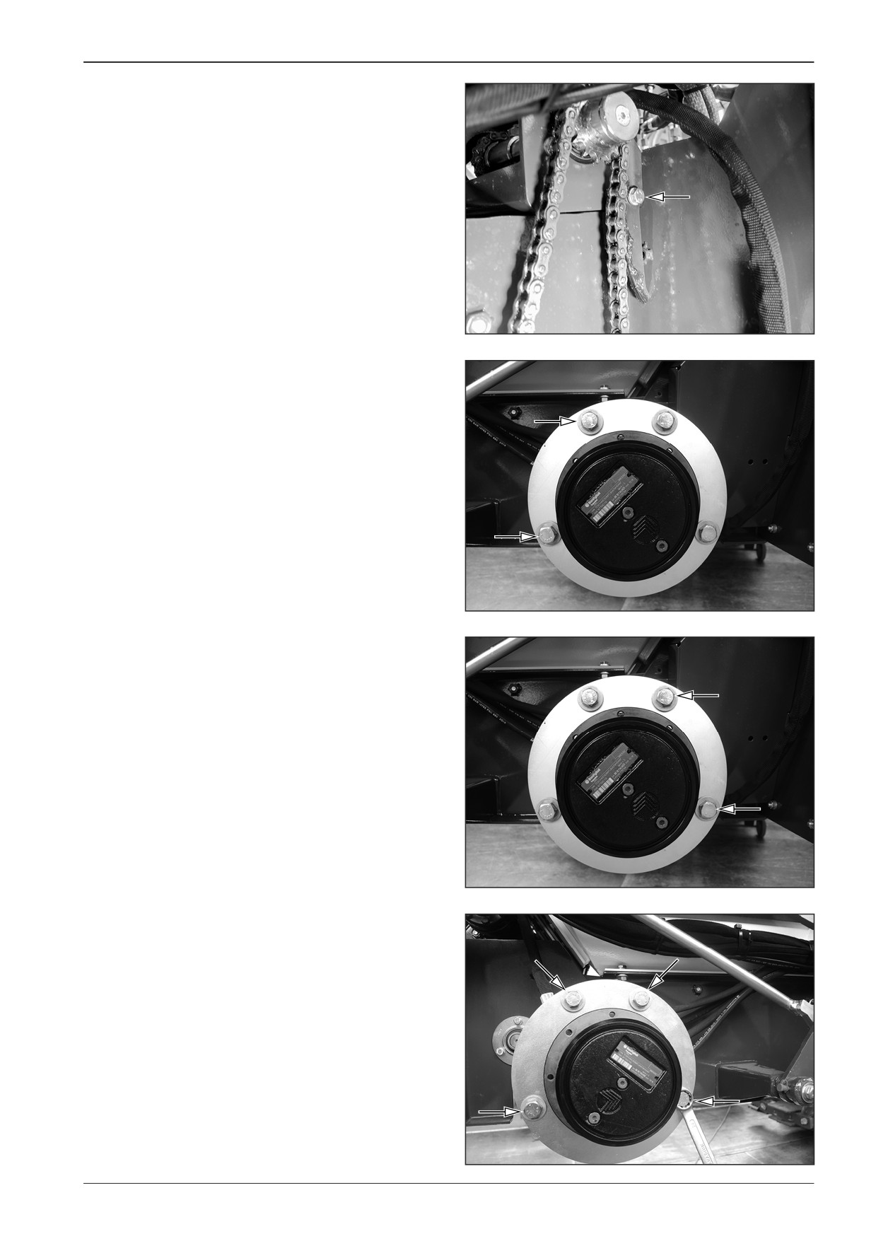
Remove the tension screw for the belt conveyor drive and mo-
tor cover.
•
Tighten the hydraulic motor screws (2x).
D451540
•
Mount the screws of the hydraulic motor (2x).
D451539
Note
Secure the screws of the hydraulic motor
(4x) with the
LOXEAL 83.54 adhesive.
D451A522
F80W
159
14
Belt conveyors and augers
•
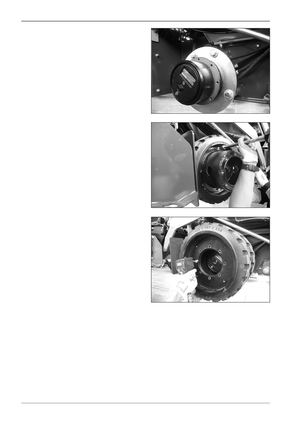
Mount the rear wheels on the left and right side of the ma-
chine.
D451519
D451518
D451517
160
F80W
WORKSHOP MANUAL
14.4
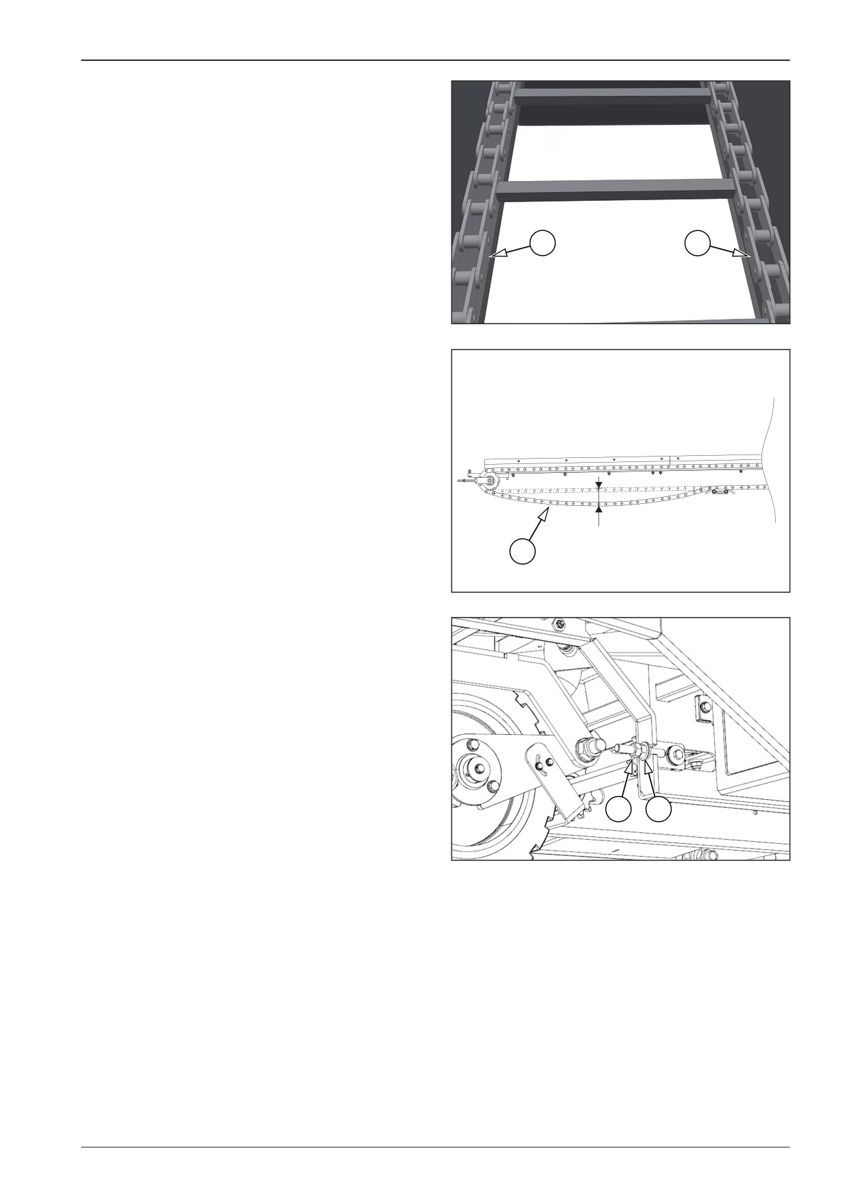
Setting the belt conveyor chain sag
Calculate the sag of the conveyor chain by measuring the dis-
tance between the ground and the left conveyor chain (1) or the
right conveyor chain (2), always in the central part of the chain.
The chain is correctly tensioned when there is an approx.
30 - 40 mm sag (1.2 - 1.6 in) in the middle.
Chain sag calculation procedure:
1
2
•
The procedure is identical for the left (1) and right (2) con-
veyor chain.
•
Measuring the distance between the ground and the chain
in the middle part of the chain (1).
451135
•
Press the chain upwards in the middle part of the chain (1)
and measure the distance between the ground and the
chain again.
•
Calculate the sag of the chain (1) by deducting the two
measured values.
•
The chain is correctly tensioned when there is an approx.
30 - 40 mm sag (1.2 - 1.6 in) in the middle.
30-40 mm (1,2-1,6 in)
1
451200
Chain tensioning procedure:
•
The procedure is identical for the left (1) and right (2) con-
veyor chain.
•
Loosen the lock nut (4).
•
Tension the chain using the adjusting nut (5).
•
Calculate the sag of the chain (1) by deducting the two
measured values according to the procedure above.
•
If the calculated sag is in the range of 30 - 40 mm (1.2 - 1.6 in),
tighten the lock nut (4).
•
Tension the chain equally on both sides of the machine.
4
5
Note
451134
In case of too high chain tension, loosen the lock nut (4) and the
adjusting nut (5).
Calculate the sag of the chain (1) by deducting the two meas-
ured values according to the procedure above.
F80W
161
14
Belt conveyors and augers
Belt tension check:
•
Check chain movement. Start the engine.
•
Let the conveyor running in the manual mode.
•
Check the correct running of conveyor chains.
•
Stop the conveyor.
•
Turn off the engine.
Perform tensioning of the conveyor chains with the ma-
chine parked on a flat and solid surface with the engine
and battery disconnecter off.
Wear the prescribed personal protective equipment
when tensioning the conveyor chains.
There is a risk of burns from the hot parts of the conveyor.
Caution! Tension the chain equally on both sides of the
machine.
162
F80W
WORKSHOP MANUAL
14.5
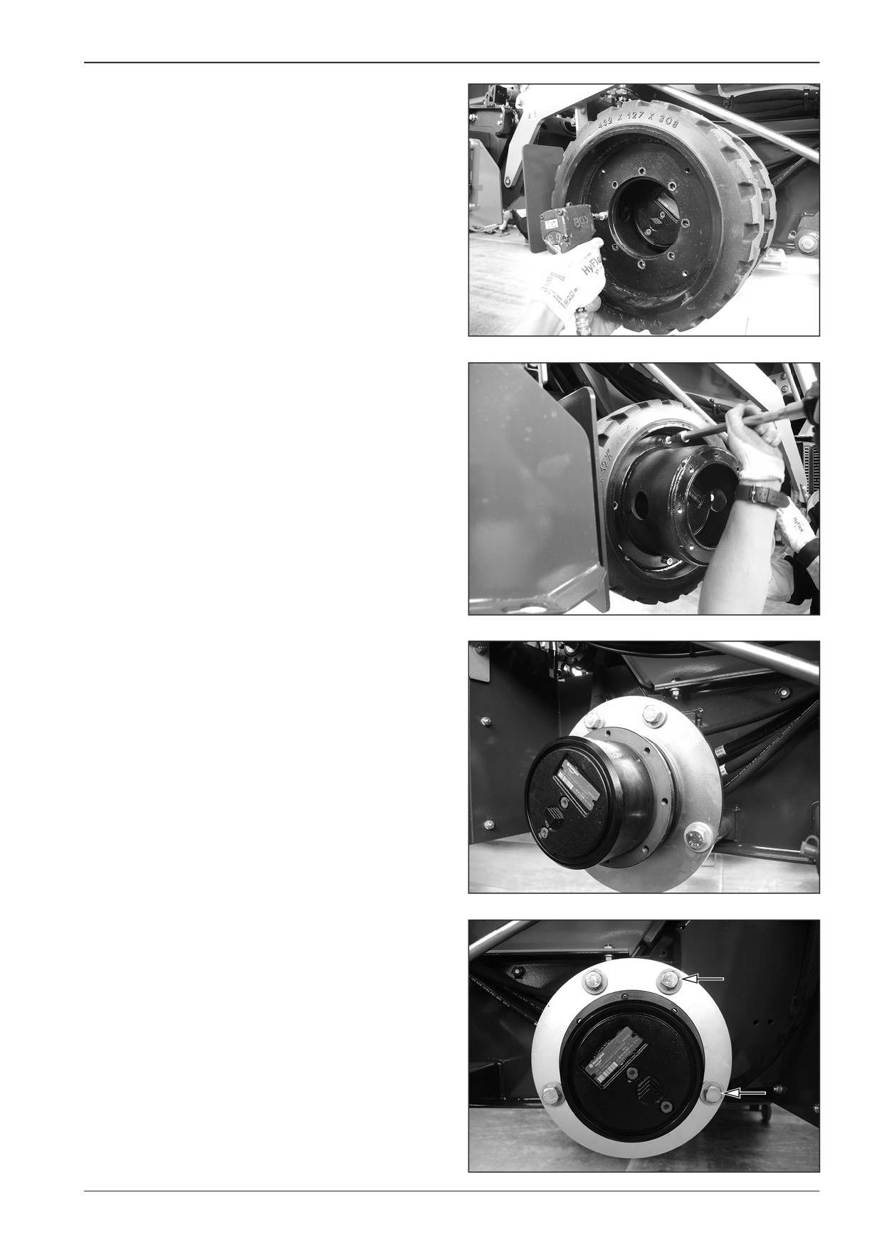
Dismounting the belt conveyor chain
drive
Dismount the belt conveyor chain drive from the machine with
the switched off battery disconnecter and with the closed gas
bottle valve.
Remove the rear wheels on the left and right side of the ma-
chine.
Remove the screws.
D451517
D451518
D451519
Remove the screws of the hydraulic motor (2x).
D451539
F80W
163
14
Belt conveyors and augers
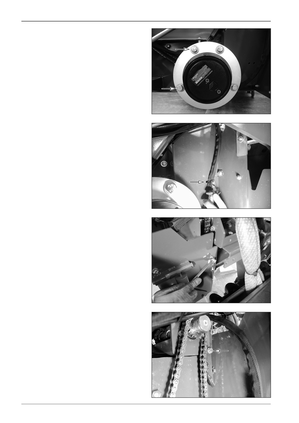
Loosen the hydraulic motor screws (2x). Pull the hydraulic motor
slightly out towards you.
D451540
Cut the binding strap of the hose.
Remove the drive cover.
D451541
Remove the tension screw for the conveyor drive.
D451542
Remove the screw.
D451543
164
F80W
WORKSHOP MANUAL
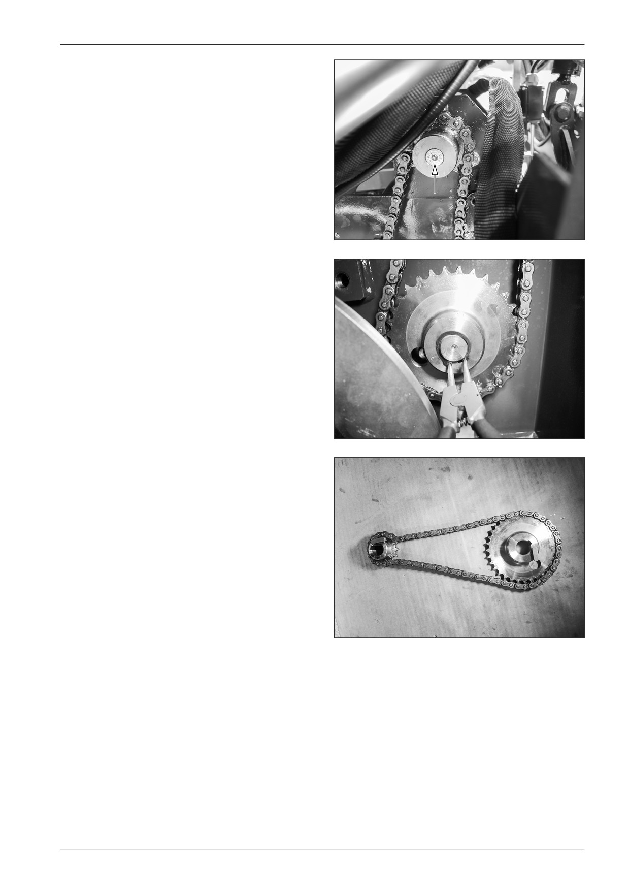
Remove the screw and the washer.
D451544
Remove the lock ring.
D451545
Remove the gear wheels with the chain for driving the belt con-
veyor.
D451546
F80W
165
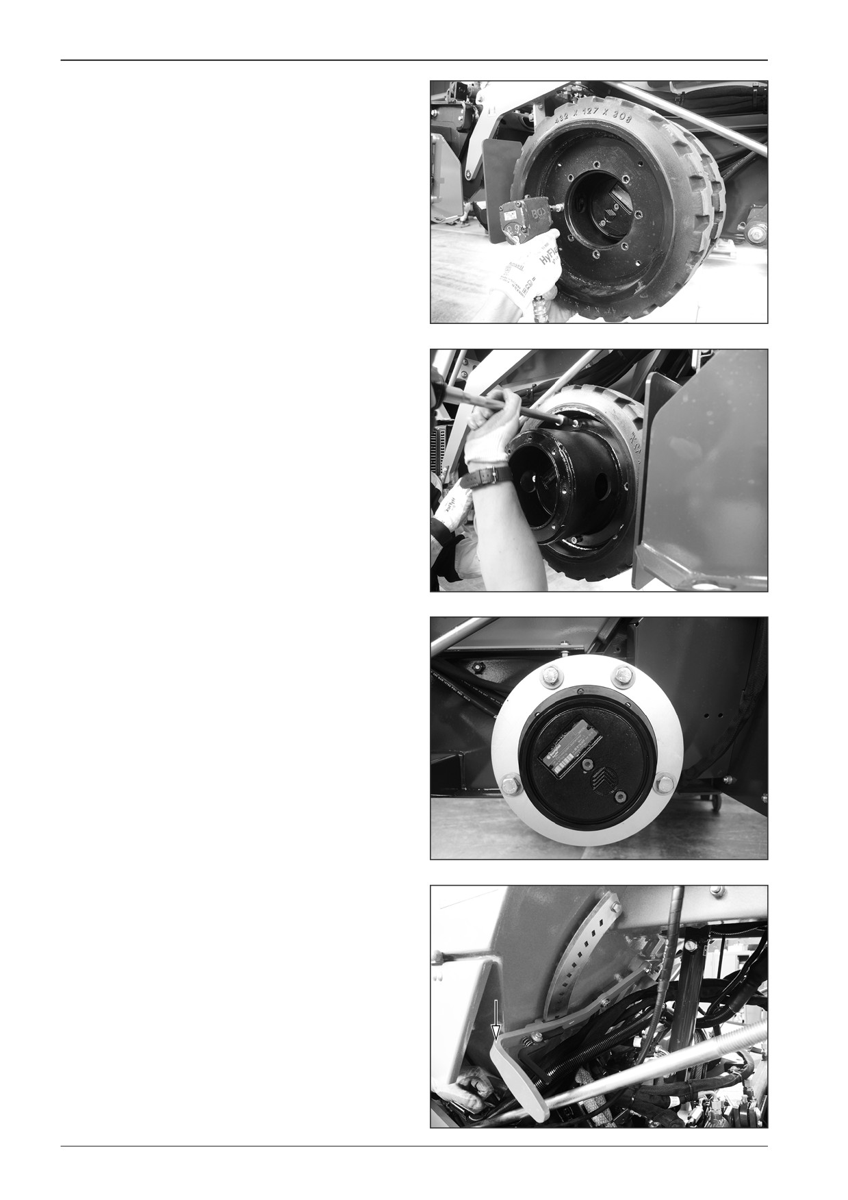
14
Belt conveyors and augers
14.6
Dismounting the auger chain
Dismount the auger chain from the machine with the switched
off battery disconnecter and with the closed gas bottle valve.
Remove the rear wheels on the left side of the machine.
Remove the screws.
D451517
DD451061
DD451060
Set the lever for material outlet to the lower position.
D421524
166
F80W
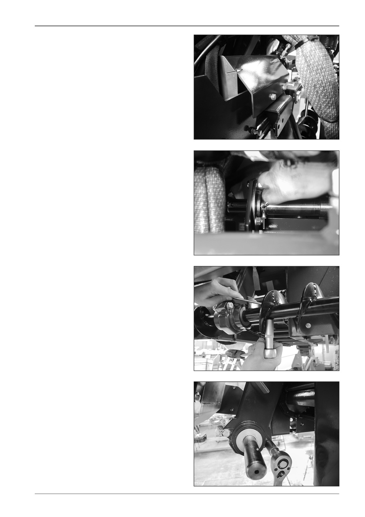
WORKSHOP MANUAL
Remove the cover.
Remove the hydraulic motor of the augers and the belt convey-
or according to Chapter 14.1.
Remove the belt conveyor chain according to Chapter 14.2.
D421525
Remove the lock screws.
D451548
Remove the augers.
Remove the lock screw.
D451549
Remove the lock screws.
D451550
F80W
167
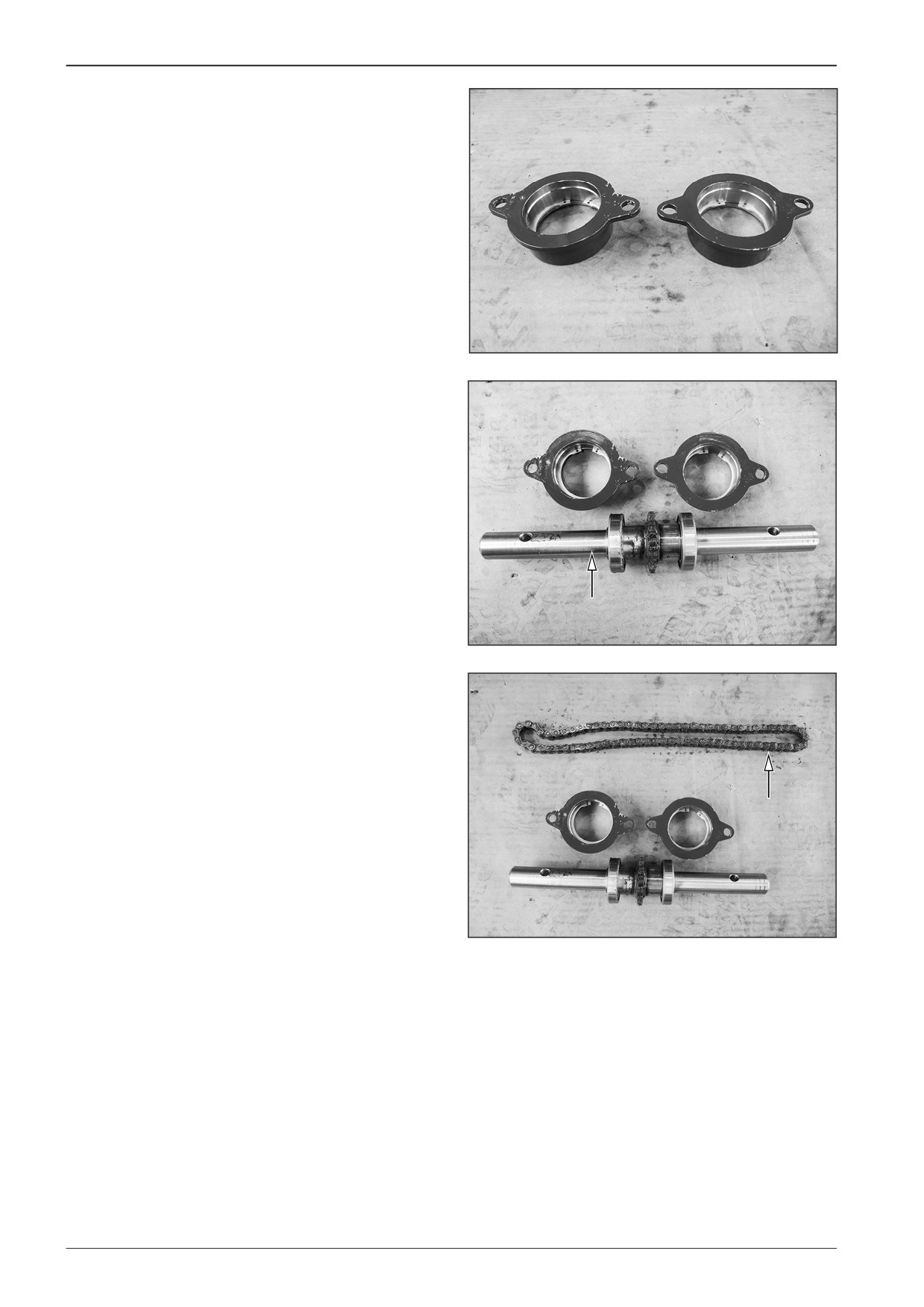
14
Belt conveyors and augers
Remove the bearing housing on the left and right side.
D451551
Take the shaft out.
D451552
Pull out the auger chain.
Note
Proceed in the reverse order when reassembling the auger
chain.
D451553
168
F80W
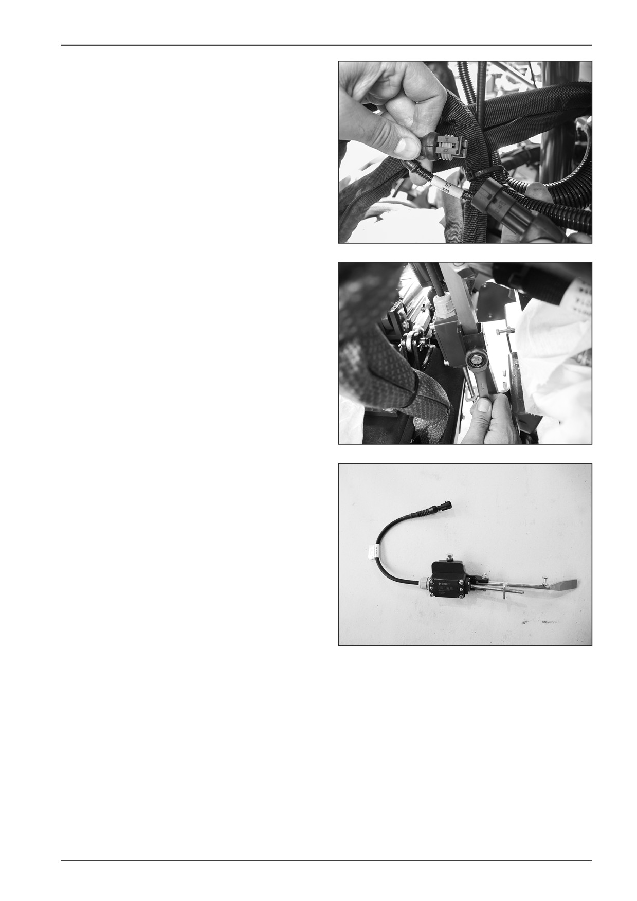
WORKSHOP MANUAL
14.7
Replacement of the drive switch of
augers and belt conveyor
Perform the replacement of the drive switch of augers and belt
conveyor on the machine with the switched off battery discon-
necter and with the closed gas bottle valve.
Disconnect the connector X43.
D451554
Remove the adjusting screw.
D451555
Take out the switch.
D451556
F80W
169