Dynapac Asphalt paver wheeled F80W Hatz. WORKSHOP MANUAL (2019) - page 3
WORKSHOP MANUAL
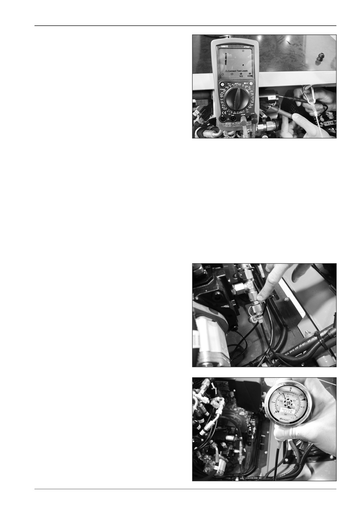
Measure the opened circuit between individual outputs and the
electromagnet body.
D451499
9.2.3
Measuring the refilling pressure
Measure the pressure using a pressure gauge with a suitable
range.
Connect the pressure gauge.
D451500
Start the engine and set the engine speed adjusting controller
to the maximum speed.
Measure the pressure to approximately 22 Bar.
Note
In case a different value is measured, contact your dealer or DY-
NAPAC Technical Support.
D451501
F80W
87
9
Travel
9.2.4
Measuring the maximum pressure for
forward and reverse travel
14-2SC DN08
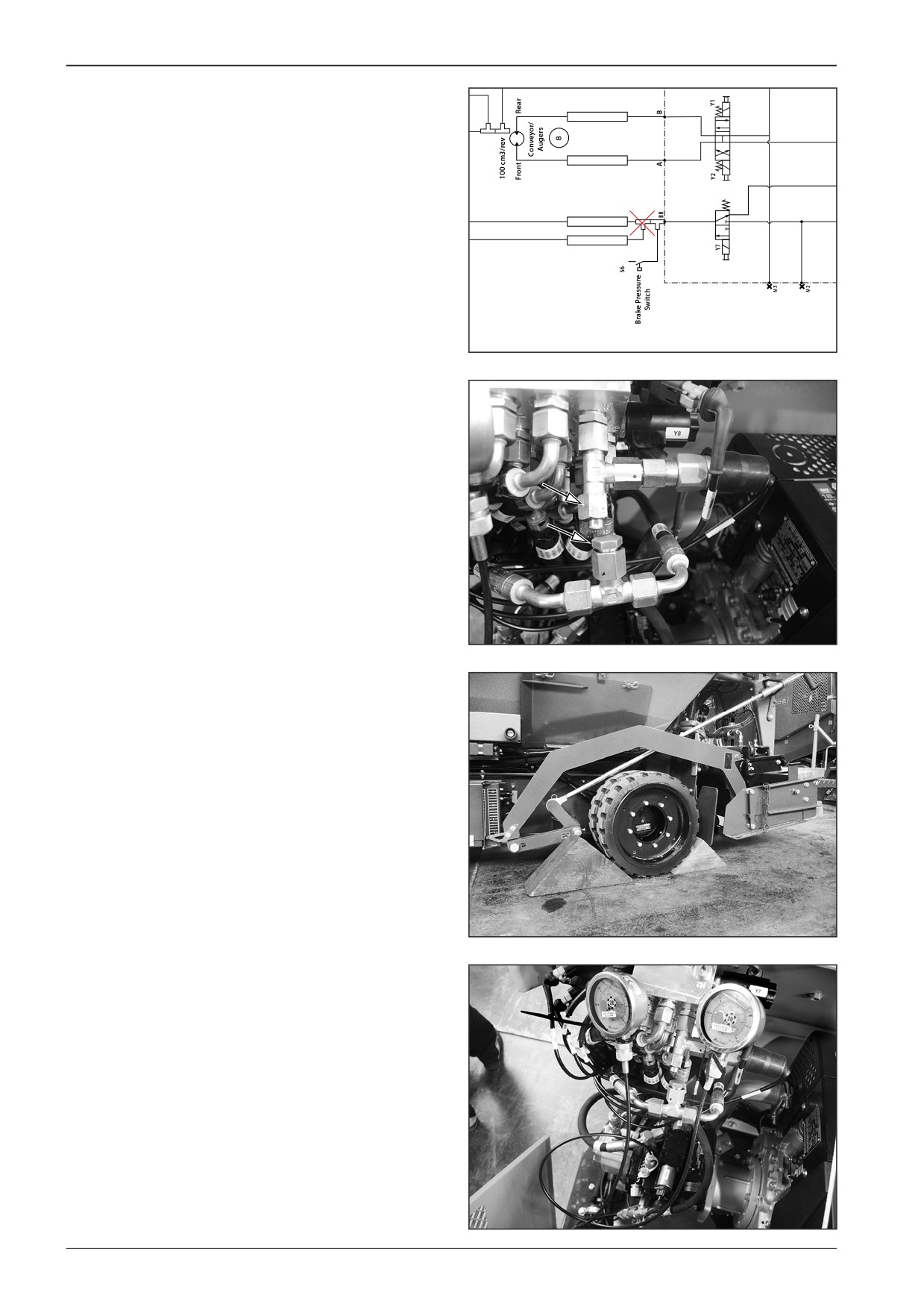
Measure the pressure using a pressure gauge with a suitable
13-2SC DN08
range.
Disable the brake release function.
22-1SC DN08
27-1SC DN08
451502
D451A503
Secure the machine against travel.
Start the engine and set the engine speed adjusting controller
to the maximum speed.
D451504
Connect the pressure gauge to the ports on the pump.
D451505
88
F80W
WORKSHOP MANUAL
D451506
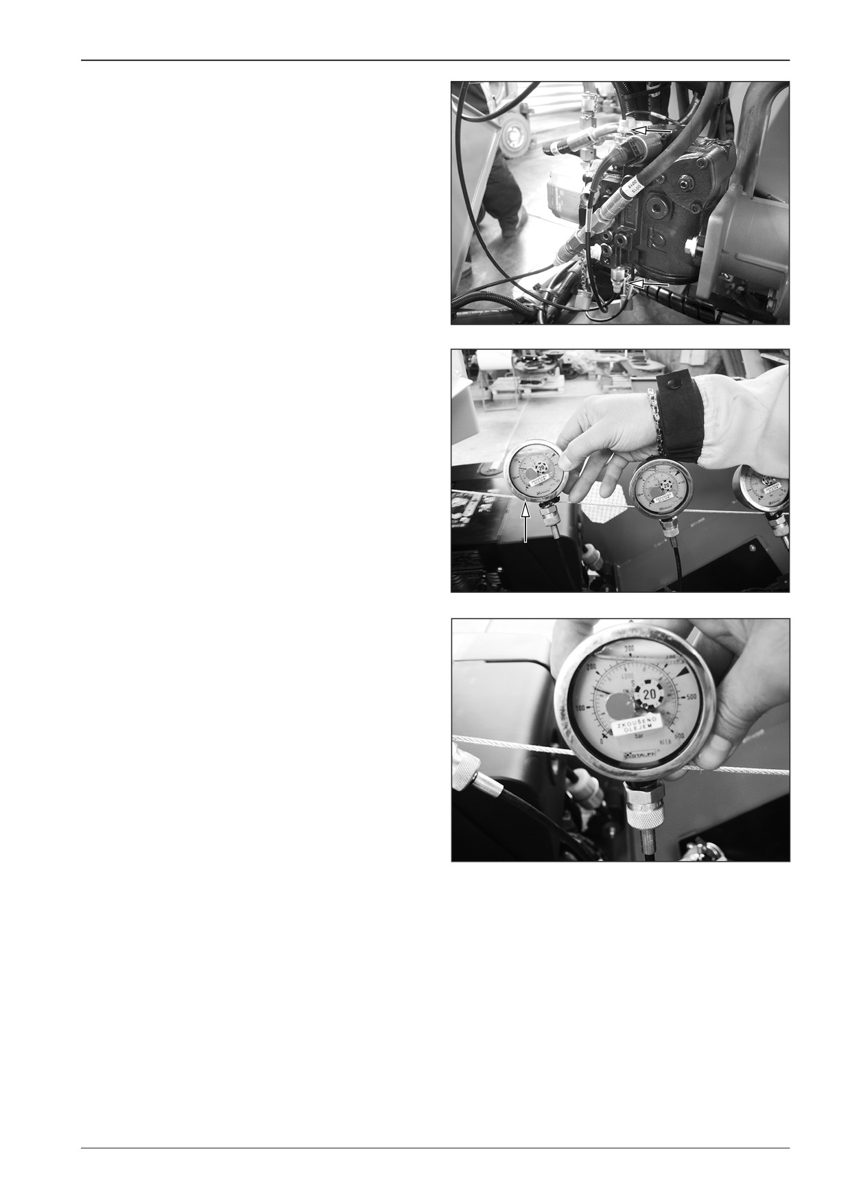
Measure the maximum pressure to approximately 150 Bar.
Note
In case a different value is measured, contact your dealer or DY-
NAPAC Technical Support.
D451507
D451508
F80W
89
9
Travel
9.2.5
Measuring the resistance of the
electromagnet coil
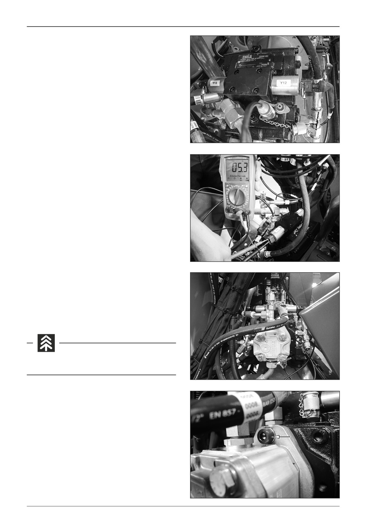
Disconnect the connectors from the coils of electromagnets Y12
and Y13.
Y12 - for forward travel
Y13 - for reverse travel
D451509
Measure the resistance of approximately 5.3 Ω between out-
puts of the coil of electromagnets Y12 and Y13.
Note
There must be an opened circuit between individual inputs and
the body of the coil.
D451510
9.3
Removal of the travel pump
Dismount the travel pump from the machine with the switched
off battery disconnecter and with the closed gas bottle valve.
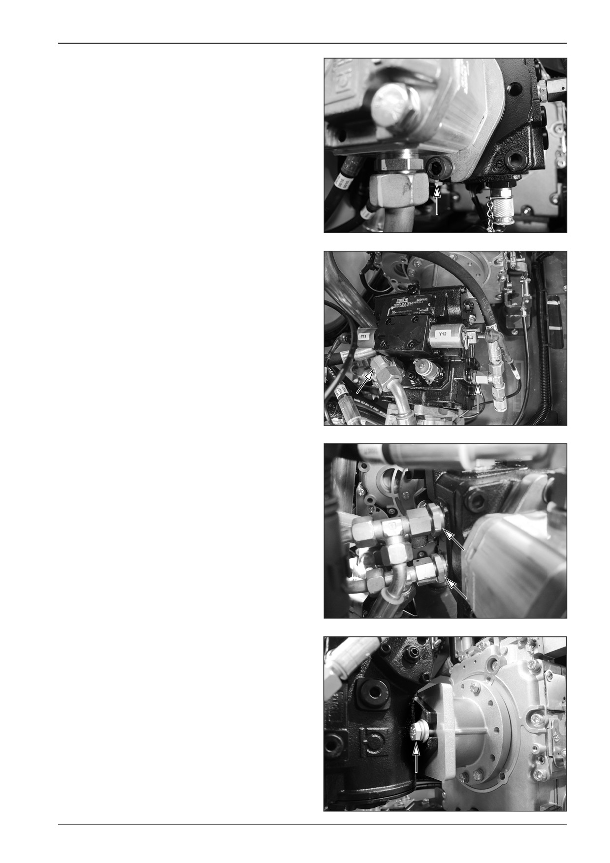
Remove the suction and discharge hose of the travel pump.
Avoid the oil soaking into the ground.
D451511
Remove the screws (2x).
D451512
90
F80W
WORKSHOP MANUAL
D451513
Remove all hoses from the pump.
D451514
D451515
Remove pump bolts.
D451516
F80W
91
9
Travel
9.4
Dismounting the hydraulic motor and
travel gearbox
Dismount the hydraulic motor and travel gearbox from the ma-
chine with the switched off battery disconnecter and with the
closed gas bottle valve.
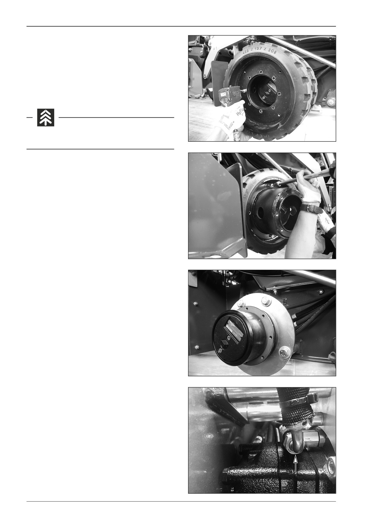
When dismounting the hydraulic motor and travel gearbox pro-
ceed in the same way on both sides of the machine.
Avoid the oil soaking into the ground.
D451517
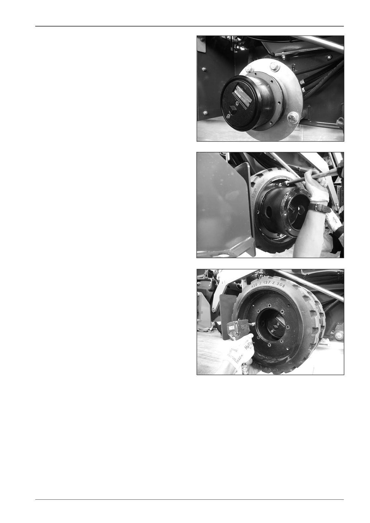
Remove the rear wheels.
Remove the screws.
D451518
D451519
Remove the hoses.
D451520
92
F80W
WORKSHOP MANUAL
D451521
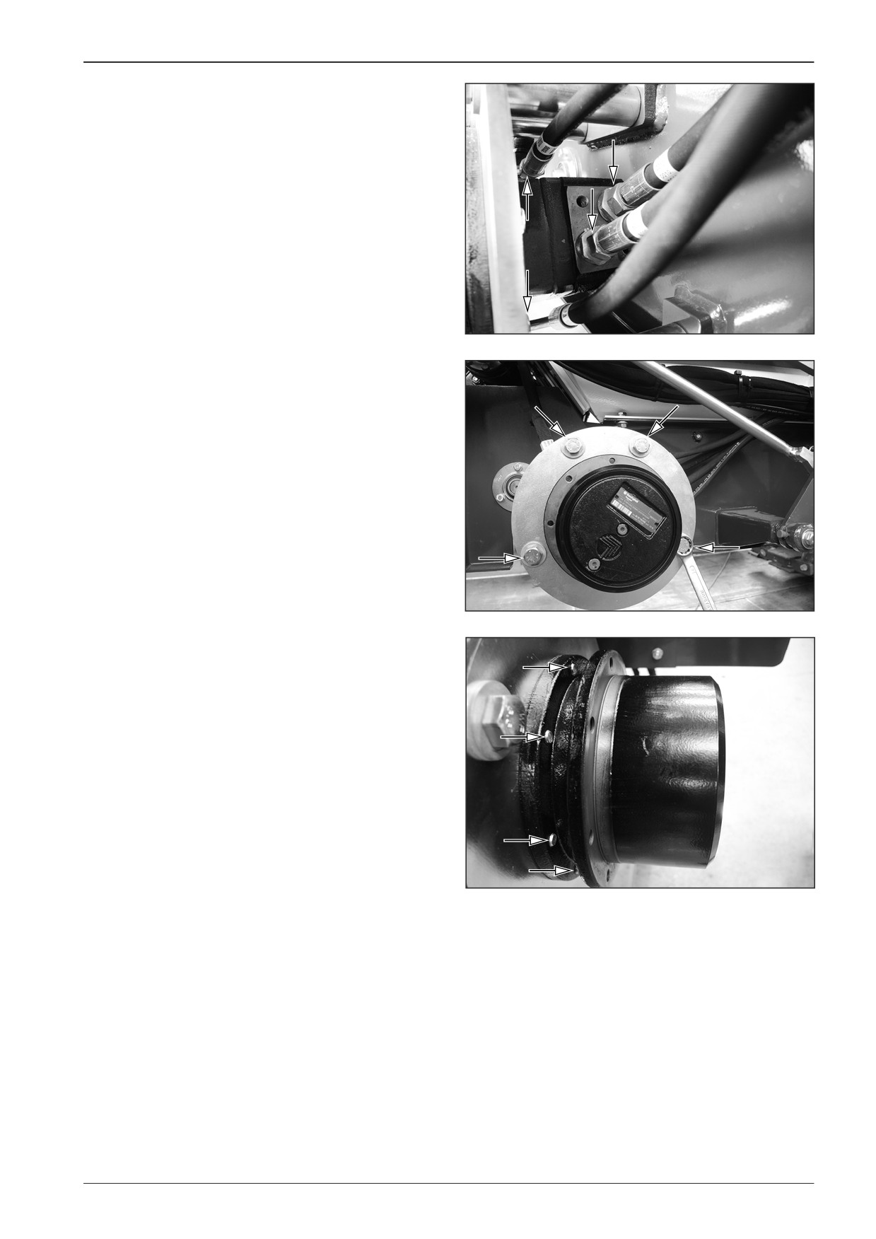
Remove the screws.
D451A522
Remove the screws (8x).
DD451023
F80W
93
9
Travel
9.5
Mounting the hydraulic motor and travel
gearbox
Mount the hydraulic motor and travel gearbox to the machine
with the switched off battery disconnecter and with the closed
gas bottle valve.
When mounting the hydraulic motor and travel gearbox pro-
ceed in the same way on both sides of the machine.
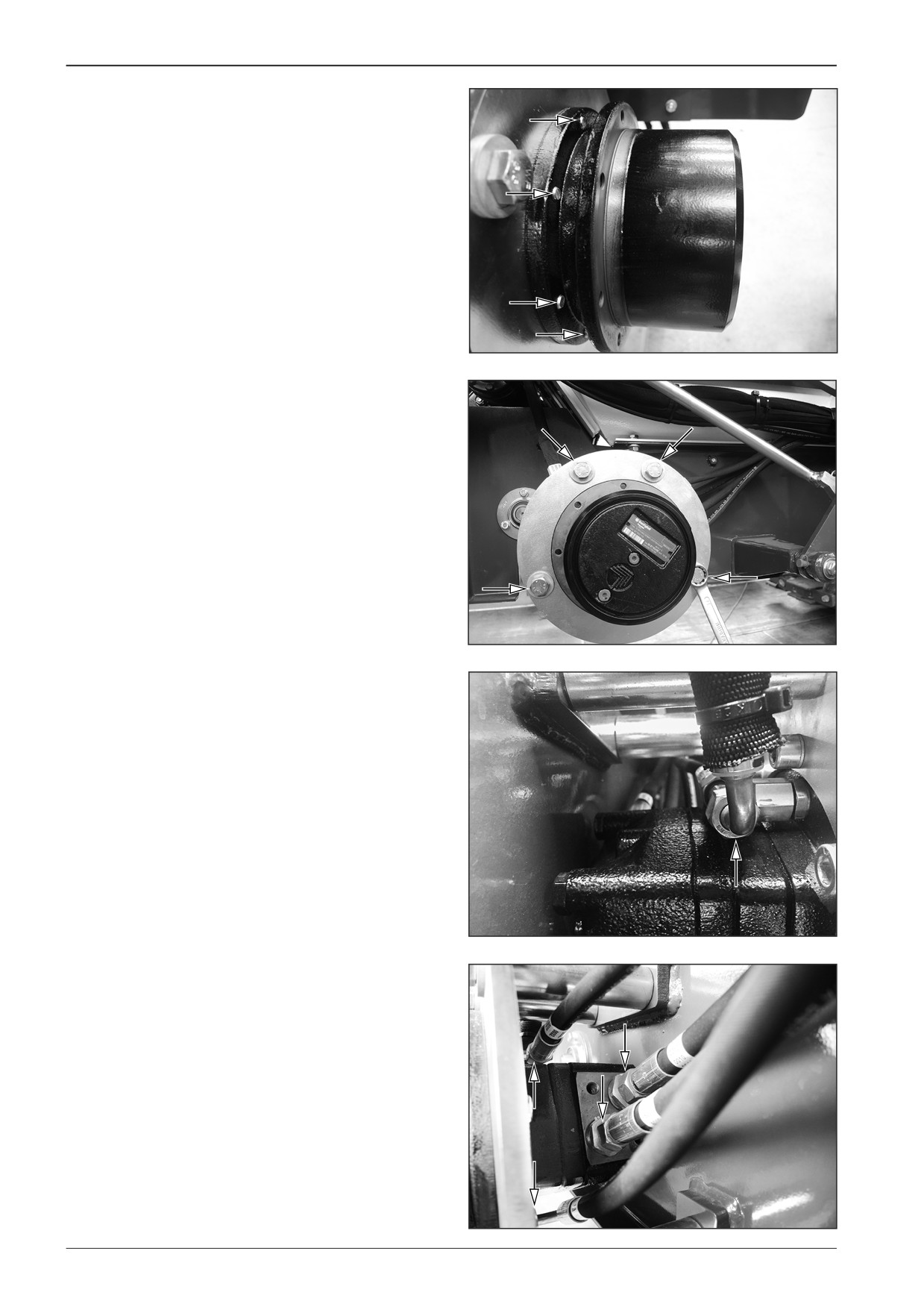
Mount the screws (8x).
DD451023
Mount the screws.
Secure the screws with the LOXEAL 83∙54 adhesive.
D451A522
Mount the hydraulic hoses.
Note
Ensure the correct connection of the hydraulic hoses.
D451520
D451521
94
F80W
WORKSHOP MANUAL
Mount the rear wheels.
Mount the screws.
D451519
D451518
D451517
F80W
95
WORKSHOP MANUAL
10
Gear pump
F80W
97
10
Gear pump
10.1
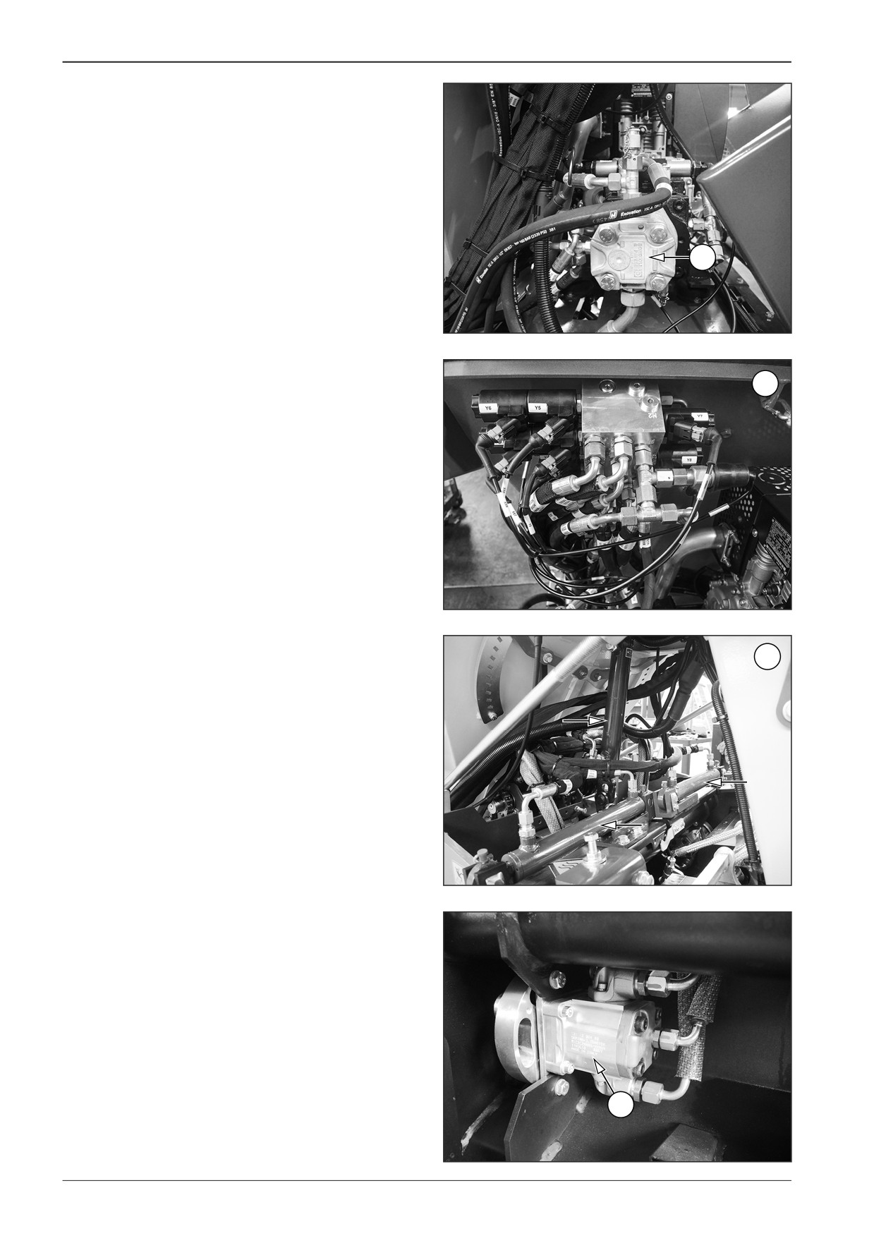
Description of basic elements
1
Gear pump
1
D451574
2
Hydraulic block
2
D451575
3
Linear hydraulic motors
3
D451576
4
Vibrators
4
D451577
98
F80W
WORKSHOP MANUAL
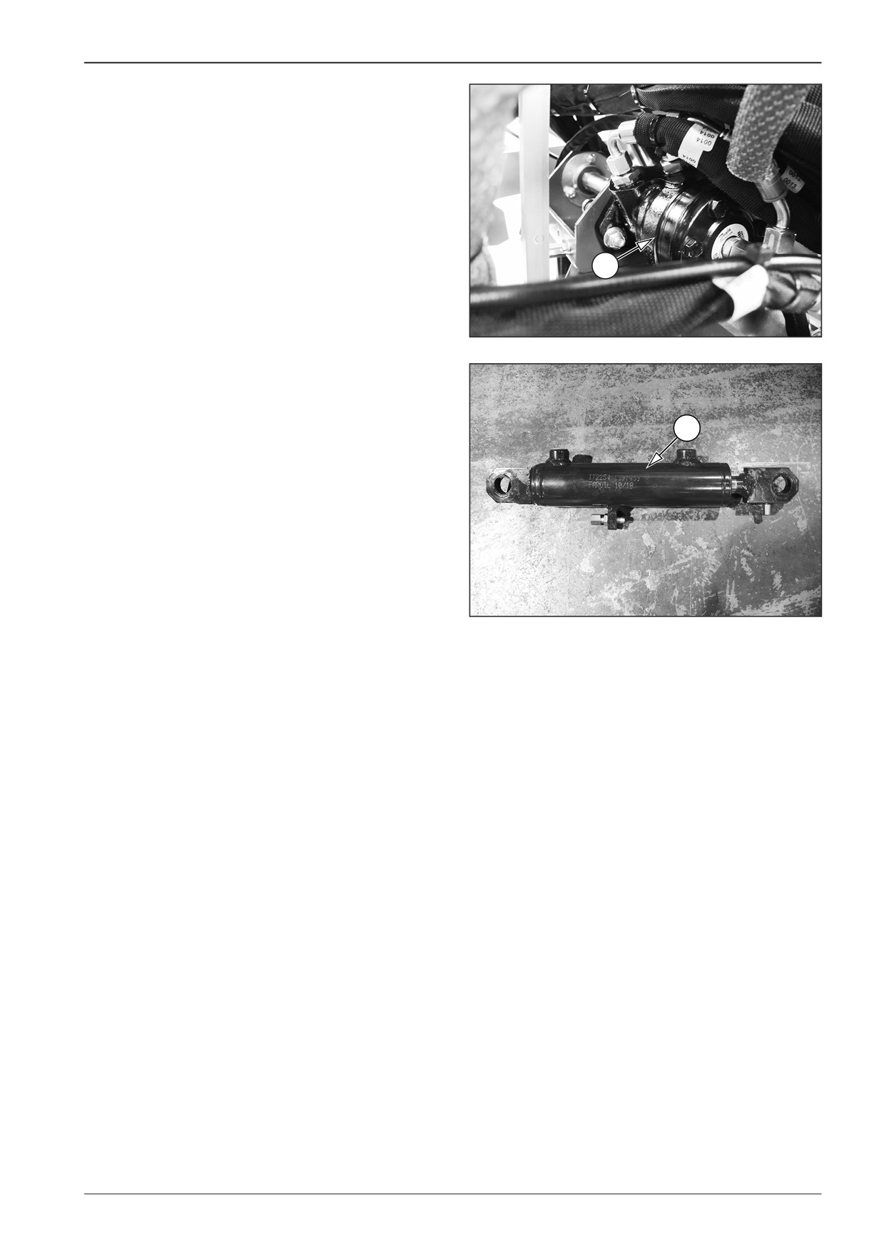
5
Hydraulic motor for driving the augers and the belt conveyor
5
D451578
6
Steering linear hydraulic motor
6
DD451057
F80W
99
10
Gear pump
10.2
Diagnostics
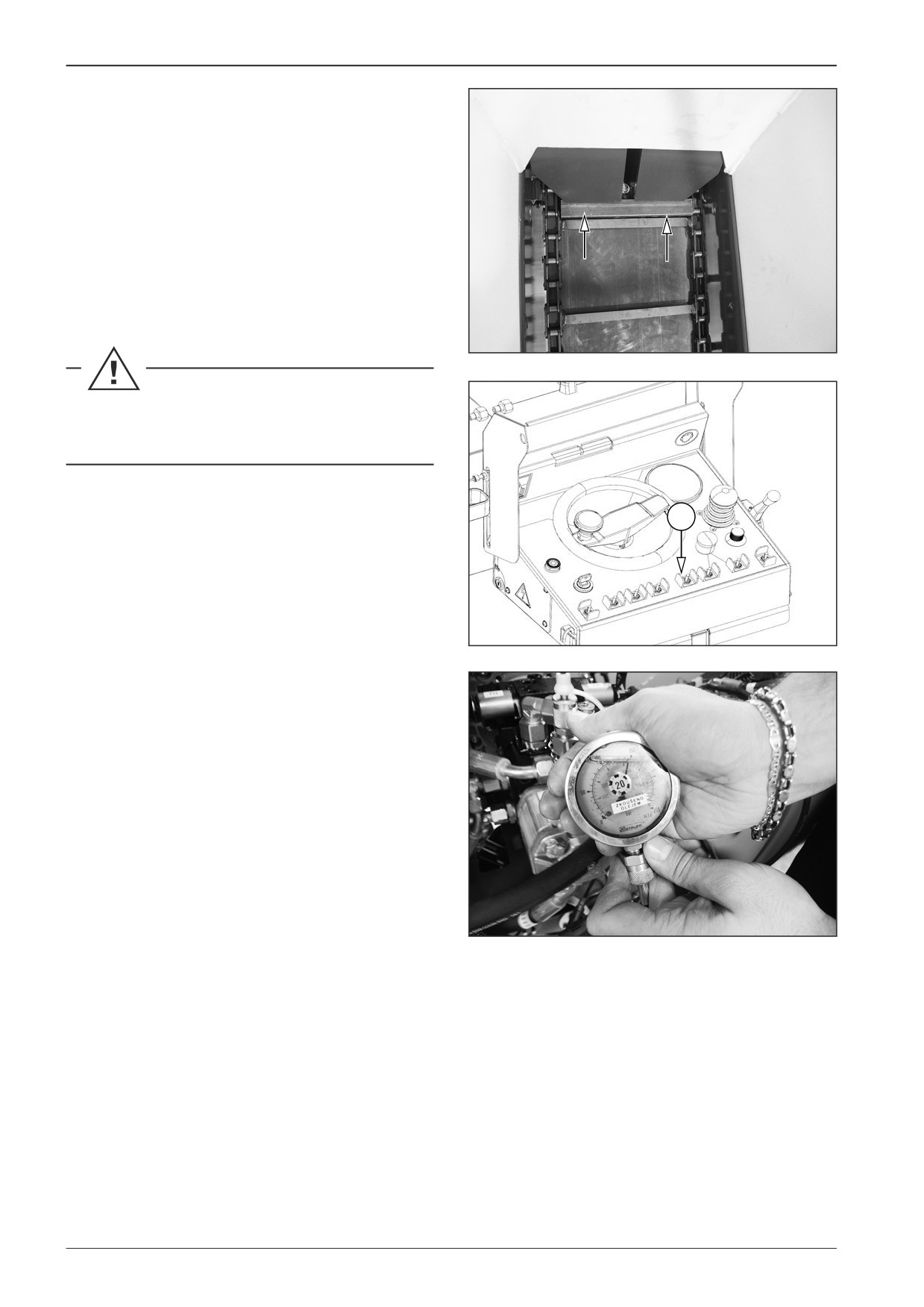
Measure the pressure in the gear pump using a suitable pressure
gauge.
10.2.1
Measuring the pressure of the belt
conveyor and auger
Start the engine.
Block the travel of the conveyor.
Start the function of the conveyor by selector switch (18).
D451579
Let the belt conveyor function running for the maximum
period of 2 sec.
18
Measure the pressure of approximately 150 Bar.
Note
In case a different value is measured, contact your dealer or
DYNAPAC Technical Support.
451585
D451580
100
F80W
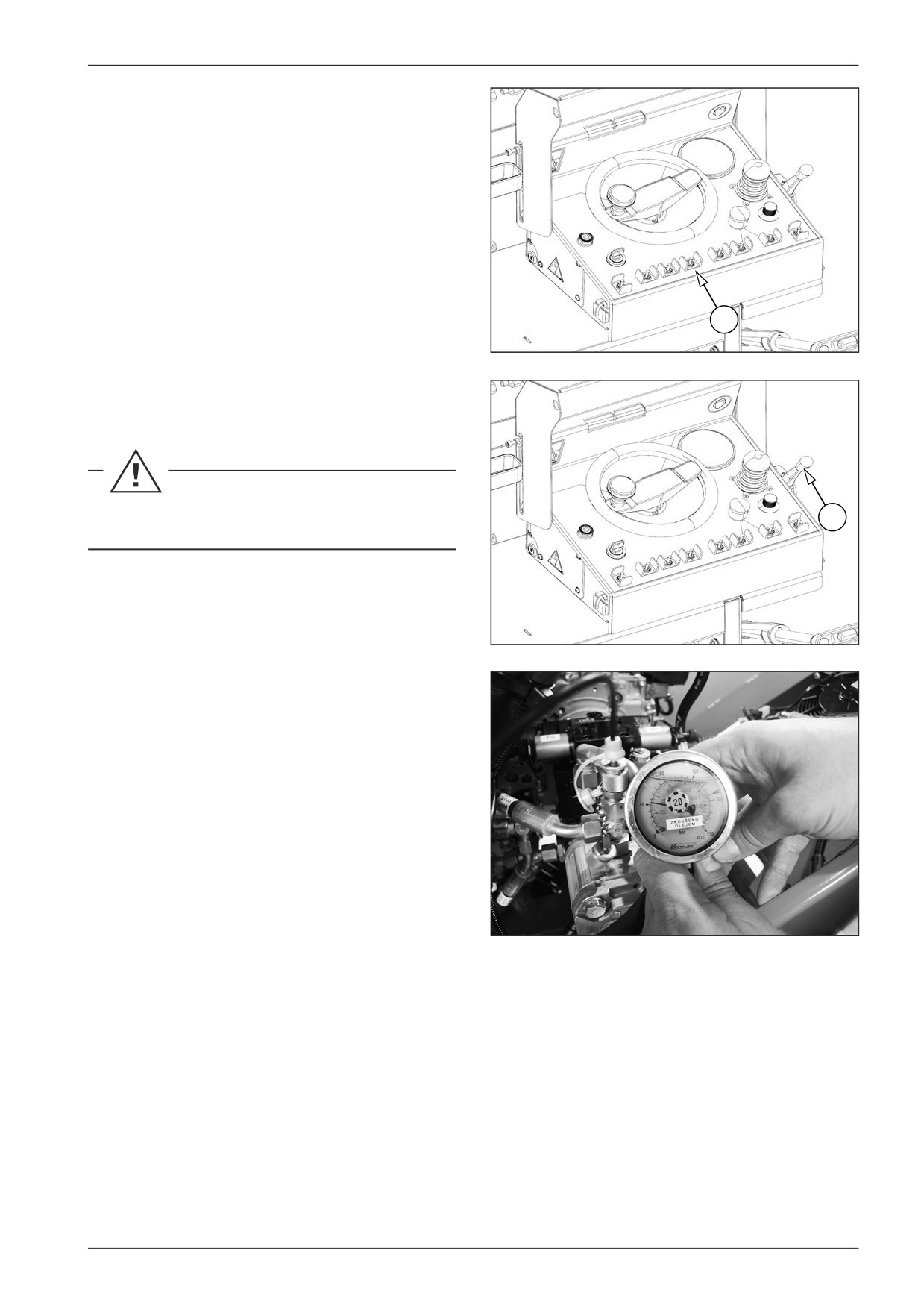
WORKSHOP MANUAL
10.2.2
Measuring the screed lifting pressure
Start the engine and lift the screed to the maximum position by
selector switch (19).
19
D451058
Set the engine speed adjusting controller (10) to the maximum
speed.
Let the engine idle for at least for 5 minutes.
10
451586
Measure the pressure of approximately 50 Bar.
Note
In case a different value is measured, contact your dealer or
DYNAPAC Technical Support.
D451581
F80W
101
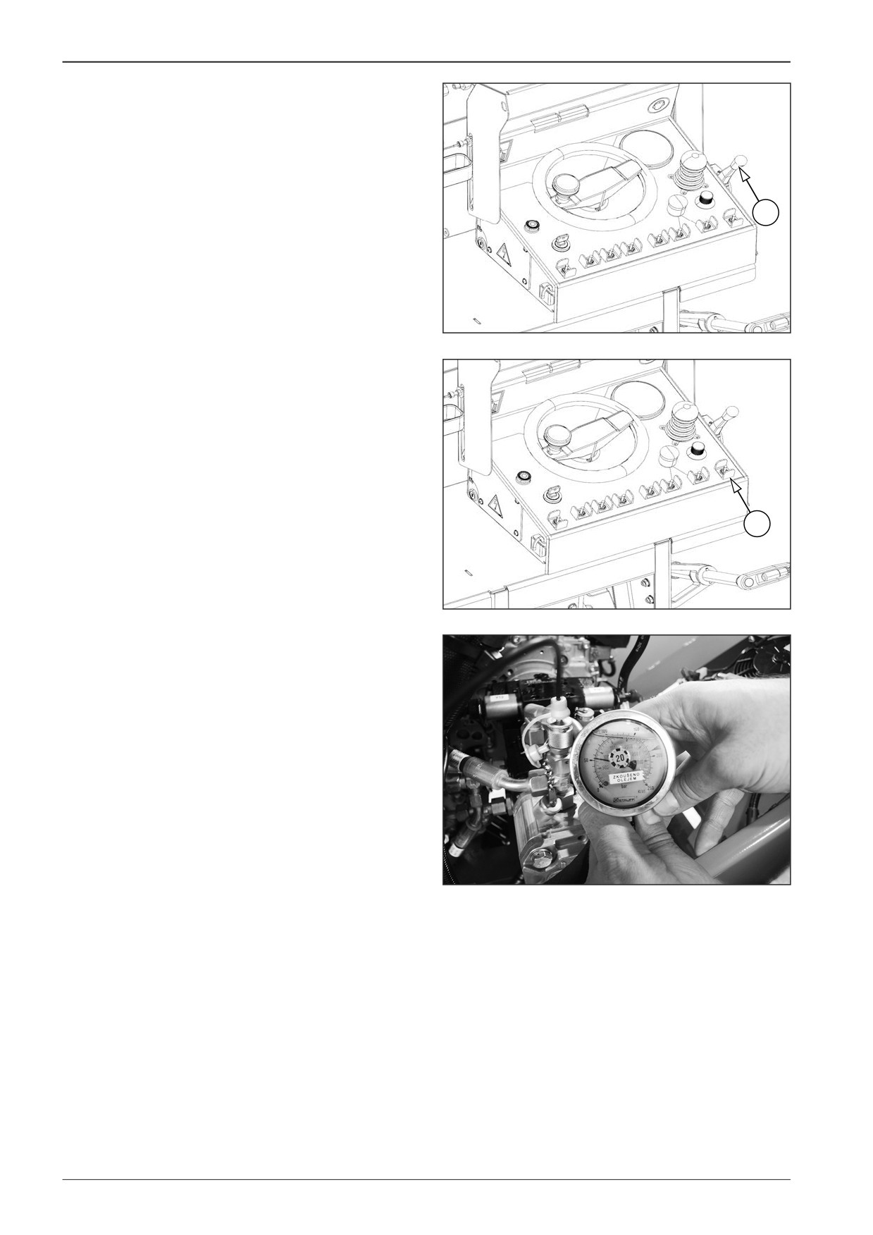
10
Gear pump
10.2.3
Measuring the screed extension pressure
Start the engine and set the engine speed adjusting controller
(10) to the maximum speed.
10
451586
Measure the pressure with the closed screed extension. Keep
the paving width switch - right (3) on the left during the meas-
urement.
3
451587
Measure the pressure of approximately 50 Bar.
Note
In case a different value is measured, contact your dealer or
DYNAPAC Technical Support.
D451581
102
F80W
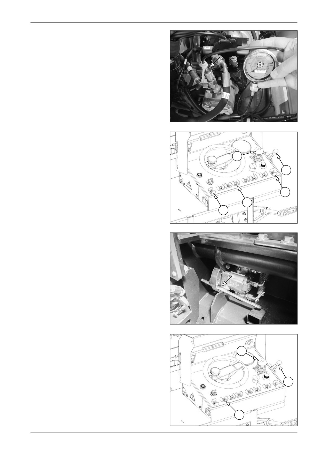
WORKSHOP MANUAL
10.2.4
Measuring the maximum vibrator
pressure
Measure the maximum vibrator pressure on the gear pump us-
ing a suitable pressure gauge.
D451632
Using the screed lift/lower switch (19) lift the screed to the maxi-
mum position.
Set the travel controller (8) to the neutral position.
Using the engine speed adjusting controller (10), set the maxi-
8
mum engine speed.
Set the screed to the maximum paving width using the paving
10
width switch - left (2) and the paving width switch - right (3).
3
19
2
451A631
Block the vibrator against movement.
D451633
Start the engine and set the engine speed adjusting controller
(10) to the maximum speed.
Set the travel control (8) to the forward position.
8
Turn the vibration unit switch (6) on the main dashboard to the
upper position.
10
6
451A586
F80W
103
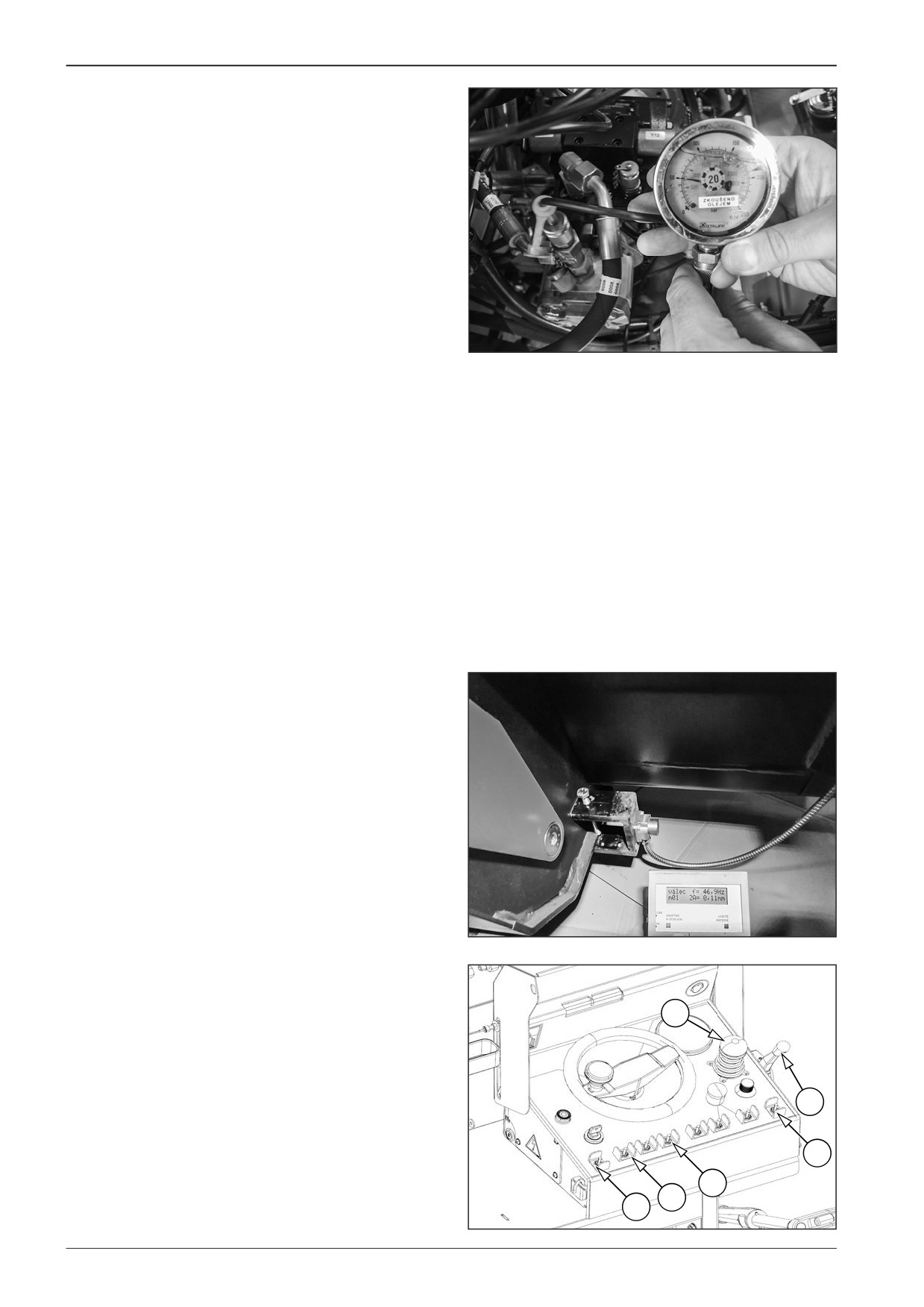
10
Gear pump
Measure the pressure of vibrators of approximately 50 Bar.
Note
In case a different value is measured, contact your dealer or
DYNAPAC Technical Support.
D451634
10.2.5
Measuring the vibration frequency
Measure the vibration frequency using a suitable vibrometer.
Start the engine.
Lift the screed to the transportation position using the screed
lift/lower switch (19) and lock it.
Adjust the maximum screed width with the controls (2) and (3)
on the control panel.
Fix the acceleration sensor of the vibrometer on the screed.
D451635
Set the engine speed adjusting controller (10) to the maximum
speed.
Set the travel control (8) to the forward position.
8
Turn the vibration unit switch (6) on the main dashboard to the
upper position.
Measure the frequency of approximately 47 Hz.
10
3
19
6
2
451B586
104
F80W
WORKSHOP MANUAL
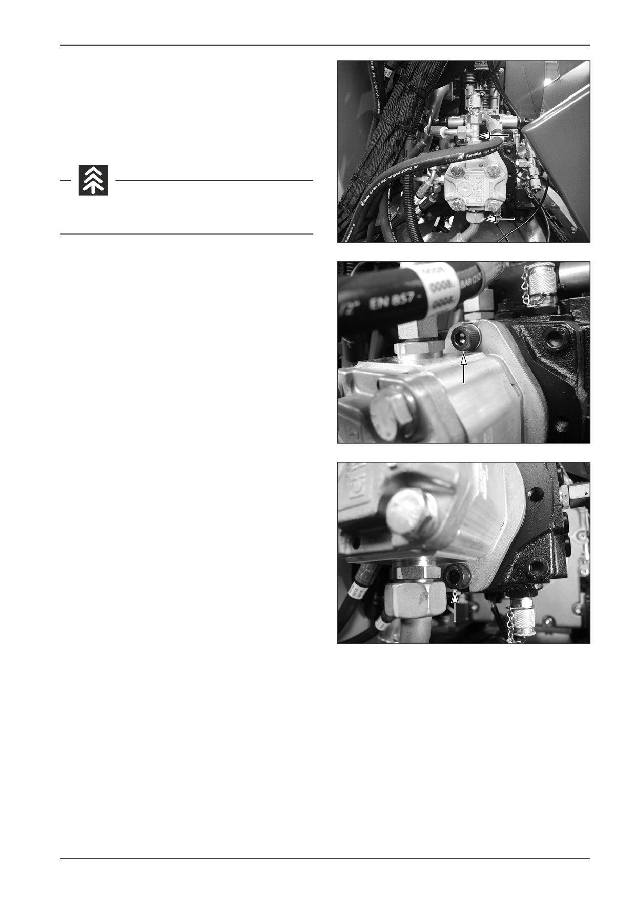
10.3. Dismounting the gear pump
Dismount the gear pump from the machine with the switched off
battery disconnecter and with the closed gas bottle valve.
Remove the suction and discharge gear pump hose.
Avoid the oil soaking into the ground.
D451452
Remove the screws.
D451453
D451454
F80W
105
10
Gear pump
10.4
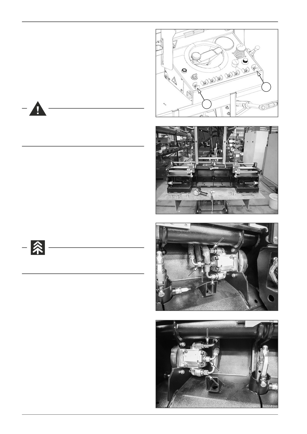
Dismounting the vibration units
Start the engine.
Adjust the maximum screed width with the controls (2) and (3)
on the control panel.
Turn off the engine, disconnect the battery disconnecter and
close the gas bottle valve.
3
2
451090A
Dismount the vibration units when the machine is
parked on a flat and solid surface, the engine and the
battery disconnecter are off and the gas bottle is closed.
D451954
Remove the hydraulic hoses.
Avoid the oil soaking into the ground.
451958
D451957
106
F80W
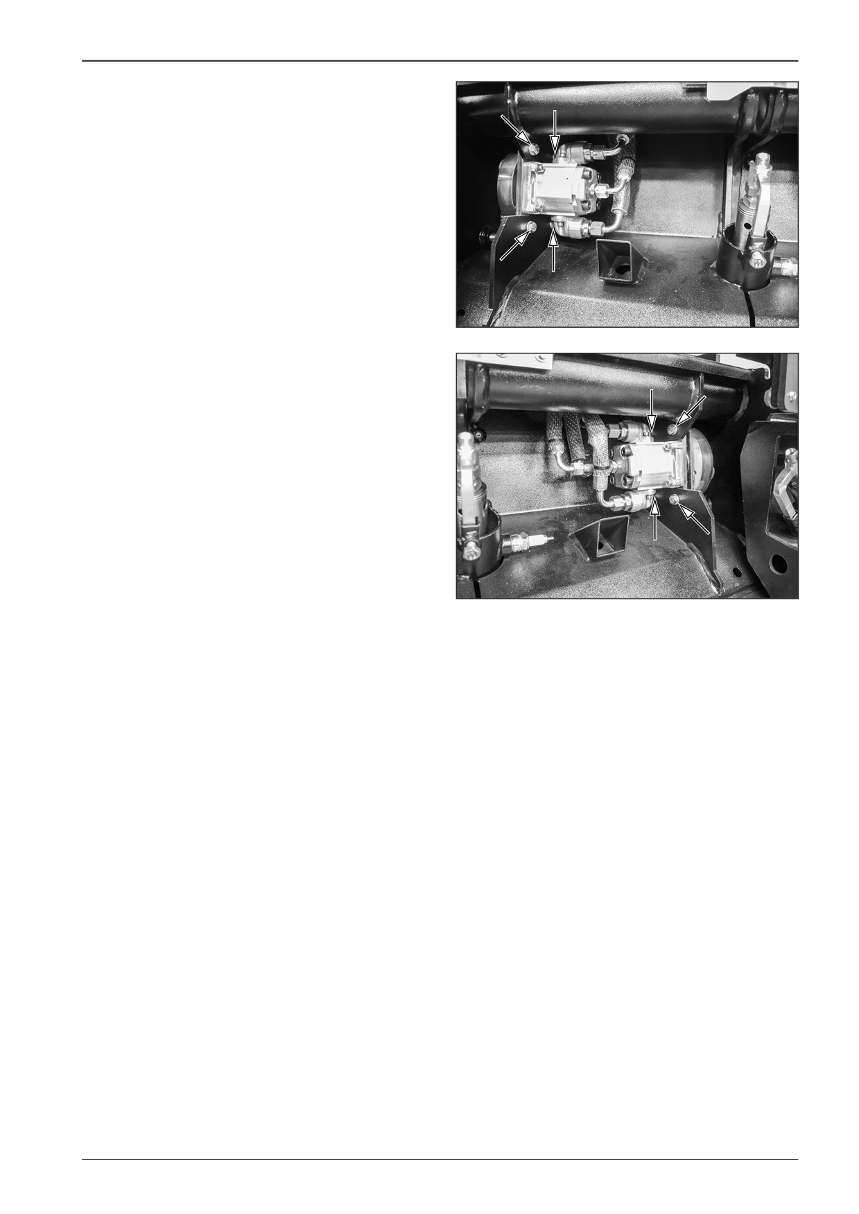
WORKSHOP MANUAL
Remove the screws.
Note
During reverse assembly glue the screws with the LOXEAL 83∙54
adhesive.
D451955
D451956
F80W
107
10
Gear pump
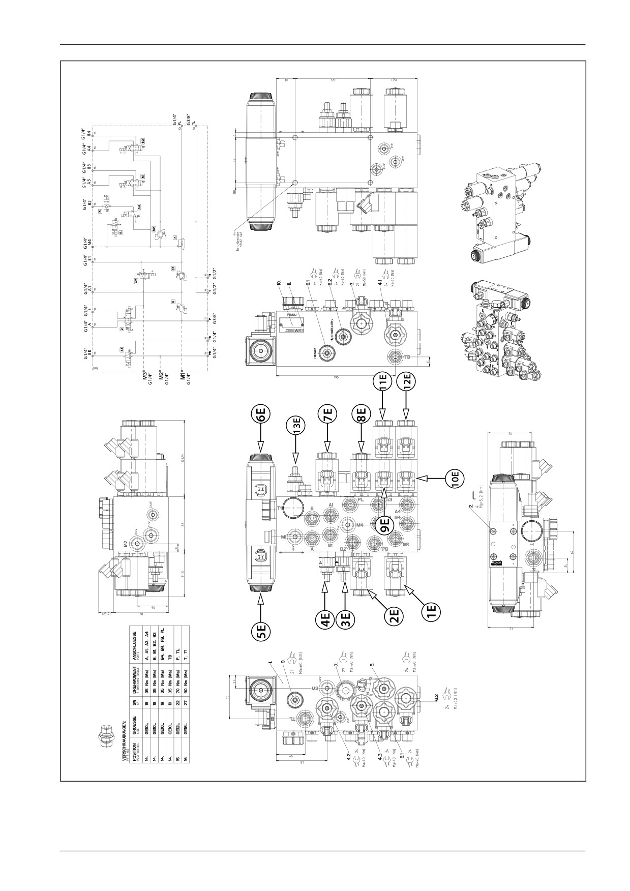
10.5
Hydraulic system switchboard
10.5.1
Description of basic elements
1E Brake electromagnet
2E Screed lowering electromagnet
3E Screed hydraulic system pressure safety valve
4E Vibration pressure safety valve
5E Conveyor electromagnet for forward direction
6E Conveyor electromagnet for reverse direction
7E Vibration electromagnet
8E Screed lifting electromagnet
9E Screed extension - left electromagnet
10E Screed closure - right electromagnet
11E Screed closure - left electromagnet
12E Screed extension - right electromagnet
13E Pressure safety valve for the drive of augers and the belt conveyor
108
F80W
WORKSHOP MANUAL
D451059
F80W
109
WORKSHOP MANUAL
11
Cooling
F80W
111
11
Cooling
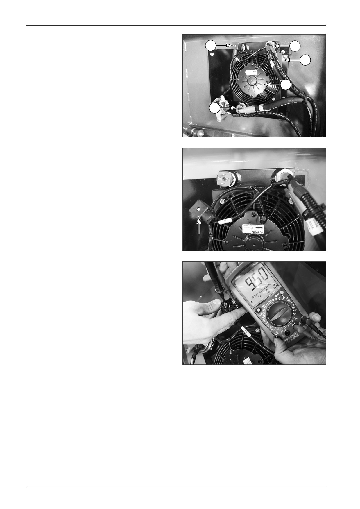
11.1
Description of basic elements
3
4
1
Cooler
2
Fan
1
3
Temperature sensor
4
Output
2
5
Input
5
D451472
11.2
Cooling diagnostics
11.2.1
Fan test
Dismount the temperature sensor connector and turn the key in
the ignition box to the “I” position. The fan will start.
D451475
11.2.2
Temperature sensor
Turn the key in the ignition box to the “I“ position.
Measure approximately 10 V between wires of connector X41.
D451476
112
F80W
WORKSHOP MANUAL
11.3
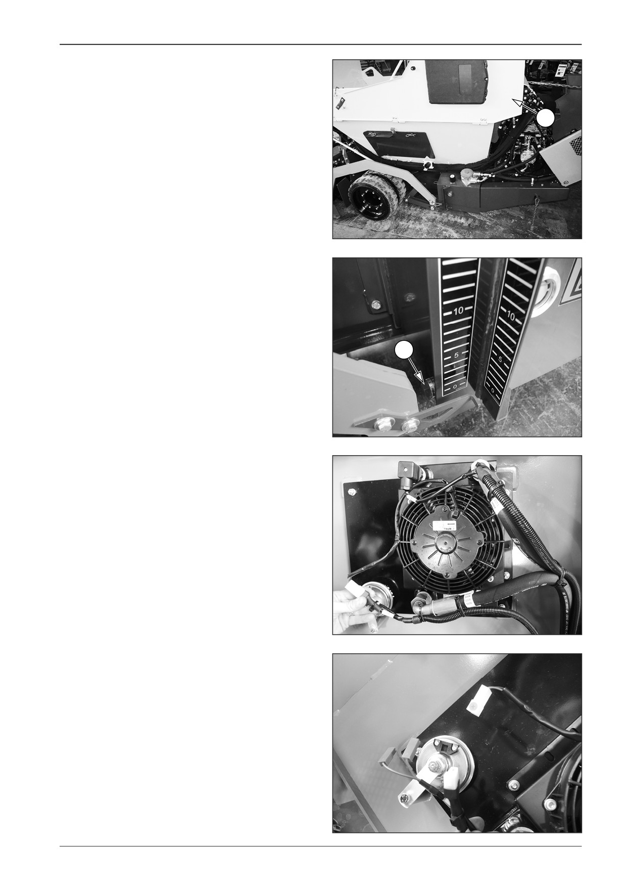
Dismounting the cooler
Drain the oil from the hydraulic tank.
Perform the hydraulic oil draining when the machine is parked
on a flat and solid surface, the battery is switched off and the gas
1
bottle is closed.
Open the right material hopper side cover (1).
Place a vessel with a volume of at least 21 l (5.5 gal US) under the
hydraulic oil drain plug (3).
Remove the drain plug (3) from the hydraulic tank.
Drain the oil into the prepared container.
Mount the drain plug (3) onto the hydraulic tank and tighten.
D451255C
3
D451A466
Disconnect the connectors X41, X19 and X20.
D451477
D451478
F80W
113
11
Cooling
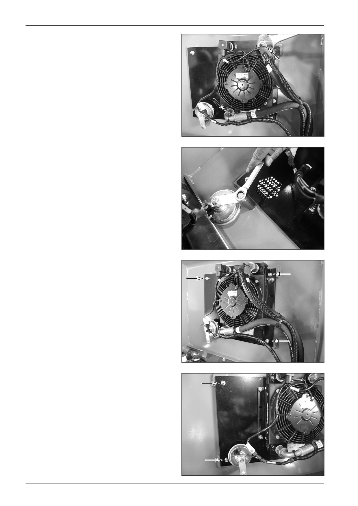
Remove the hoses of the input and output.
D451479
Loosen the screw and move the horn to the side.
D451480
Remove the screws.
D451481
D451482
114
F80W
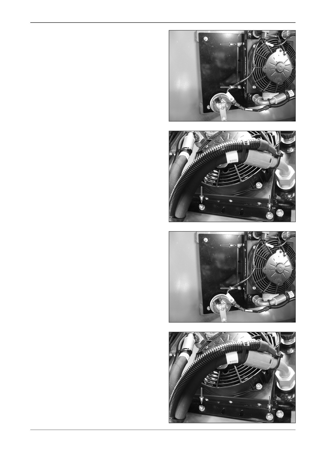
WORKSHOP MANUAL
Remove the screws.
D451483
D451484
11.4
Mounting the cooler
Mount the cooler to the machine with the switched off battery
disconnecter and with the closed gas bottle valve.
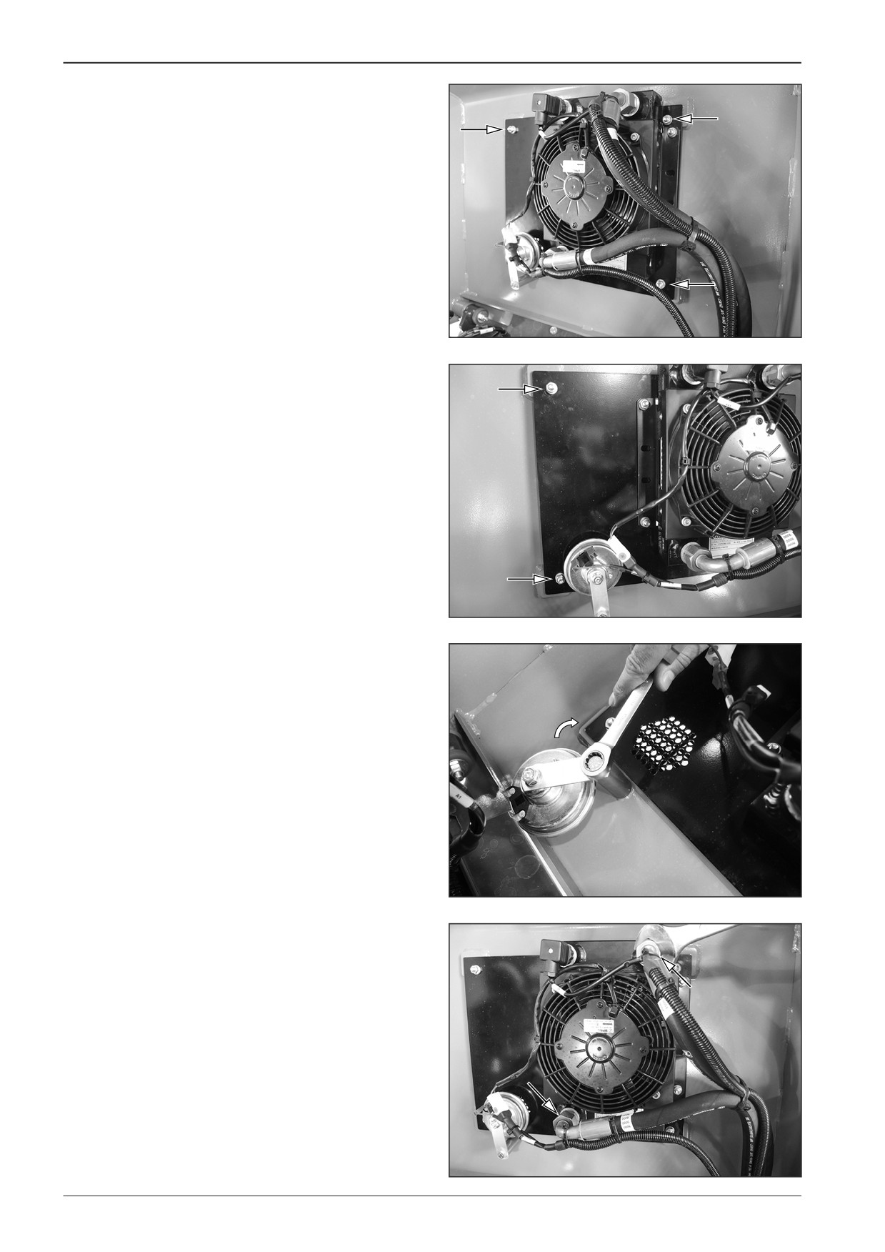
Mount the screws.
D451483
D451484
F80W
115
11
Cooling
Mount the screws.
D451481
D451482
Mount horn and tighten the screw.
D451485
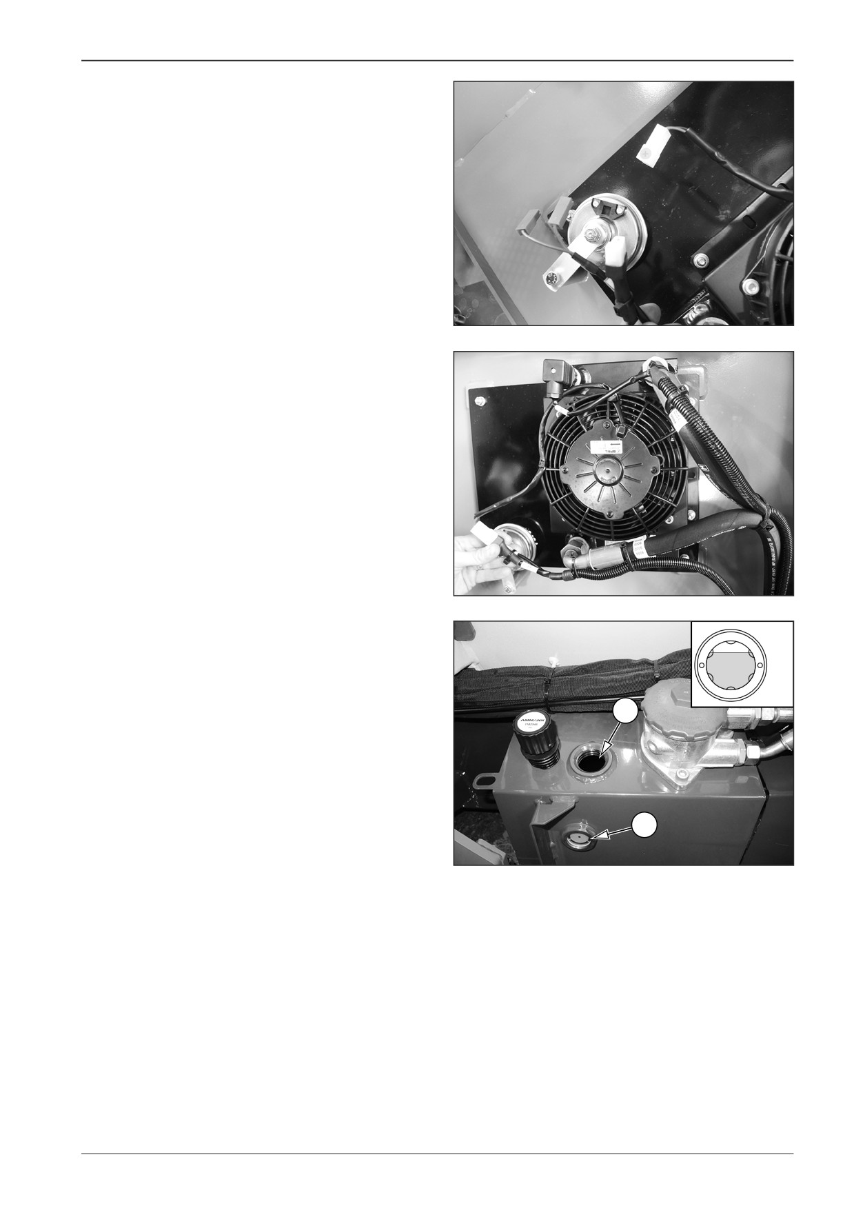
Mount the hoses of the input and output.
D451479
116
F80W
WORKSHOP MANUAL
Connect the connectors X41, X19 and X20.
D451478
D451477
Fill in the hydraulic tank.
MAX
•
Fill in new oil to the hydraulic tank through the hole (1).
•
The prescribed oil volume is 20 l (5.3 gal US).
MIN
•
Check the oil level on the oil gauge (2).
•
The hydraulic oil level must be between the MIN and MAX
1
marks.
2
D451256B
F80W
117
WORKSHOP MANUAL
12
Screed
F80W
119
12
Screed
12.1
Dismounting the screed lifting cylinder
F
8
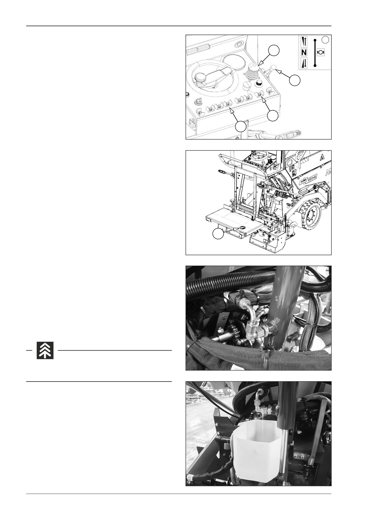
Start the engine and lower the screed to the ground.
8
0
P
•
Procedure for lowering of the screed in the transport mode:
R
--
Set the travel controller (8) to the neutral position (N).
--
Set the engine speed adjusting controller (10) to the
10
maximum speed.
--
Switch over the transport/operating mode switch (15) to
the upper position.
--
Press the foot switch (48).
15
--
To lower the screed, switch over the screed lift/lower
switch (19) down.
19
--
After reaching the required position, release the switch.
451087A
--
Release the foot switch (48).
48
451652
Turn off the engine.
Turn off the battery disconnecter and close the gas bottle valve.
Remove the hose.
Note
Place a container under the hose to trap the oil.
D451582
Avoid the oil soaking into the ground.
D451583
120
F80W
WORKSHOP MANUAL
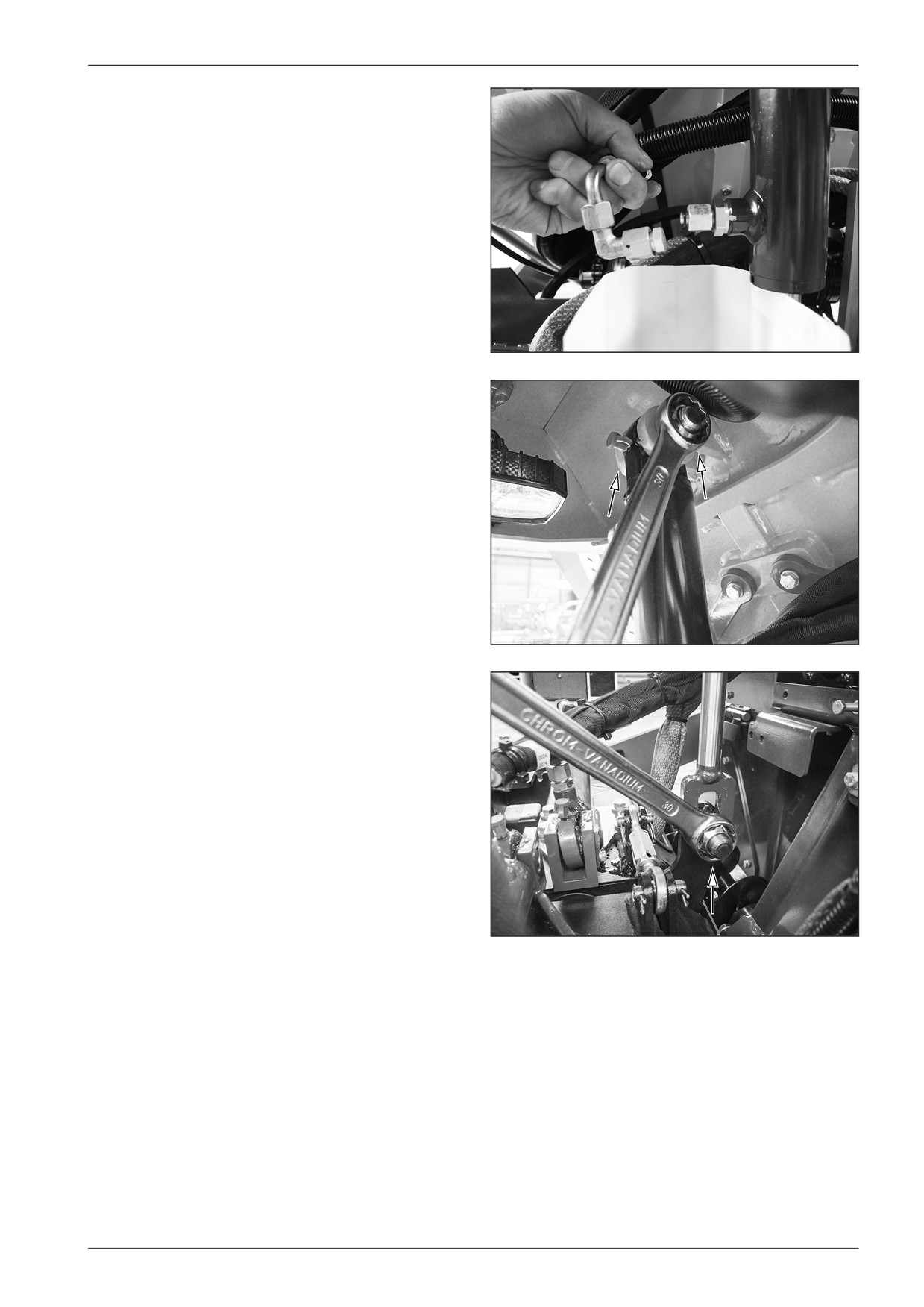
Plug both ends of the hose.
D451584
Dismount the screwed fittings.
D451589
D451590
F80W
121
12
Screed
12.2
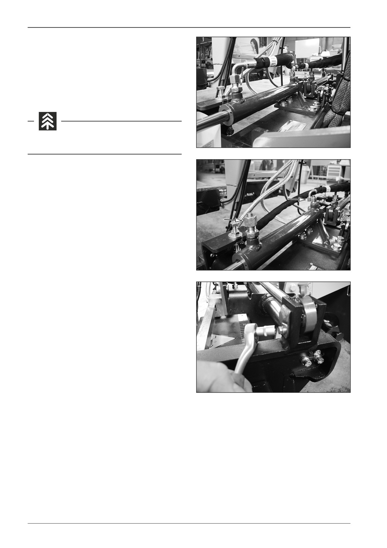
Replacement of linear hydraulic motors
for screed extension
Remove the hoses.
Note
Place a container under the hoses to trap the oil.
Avoid the oil soaking into the ground.
D451591
Plug all ends.
D451592
Remove the screw.
D451593
122
F80W
WORKSHOP MANUAL
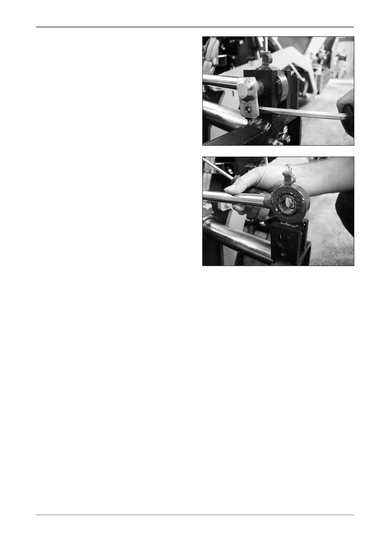
Remove the pin.
Note
Proceed in the same way on the other side of the hydraulic motor.
D451594
D451595
F80W
123
12
Screed
12.3
Basic setting of the screed
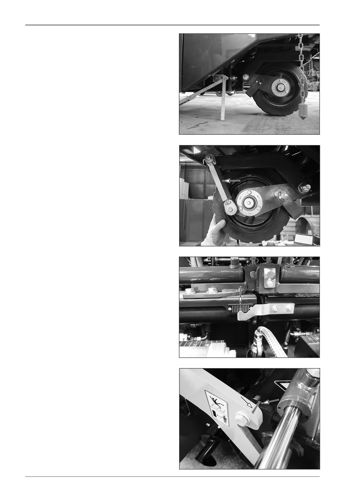
Park the machine on a flat and solid surface.
Note
Make sure that the machine is levelled by measuring the frame
distance from the ground - 12.5 cm - at the front wheel.
D451604
If a different distance is measured, adjust the height of the front
wheel to the required height.
DD451024
Check that the paving cross gradient is on the “0” position.
D451605
Check that the marks on the trailing arm and the screed match
each other.
DD451034
124
F80W
WORKSHOP MANUAL
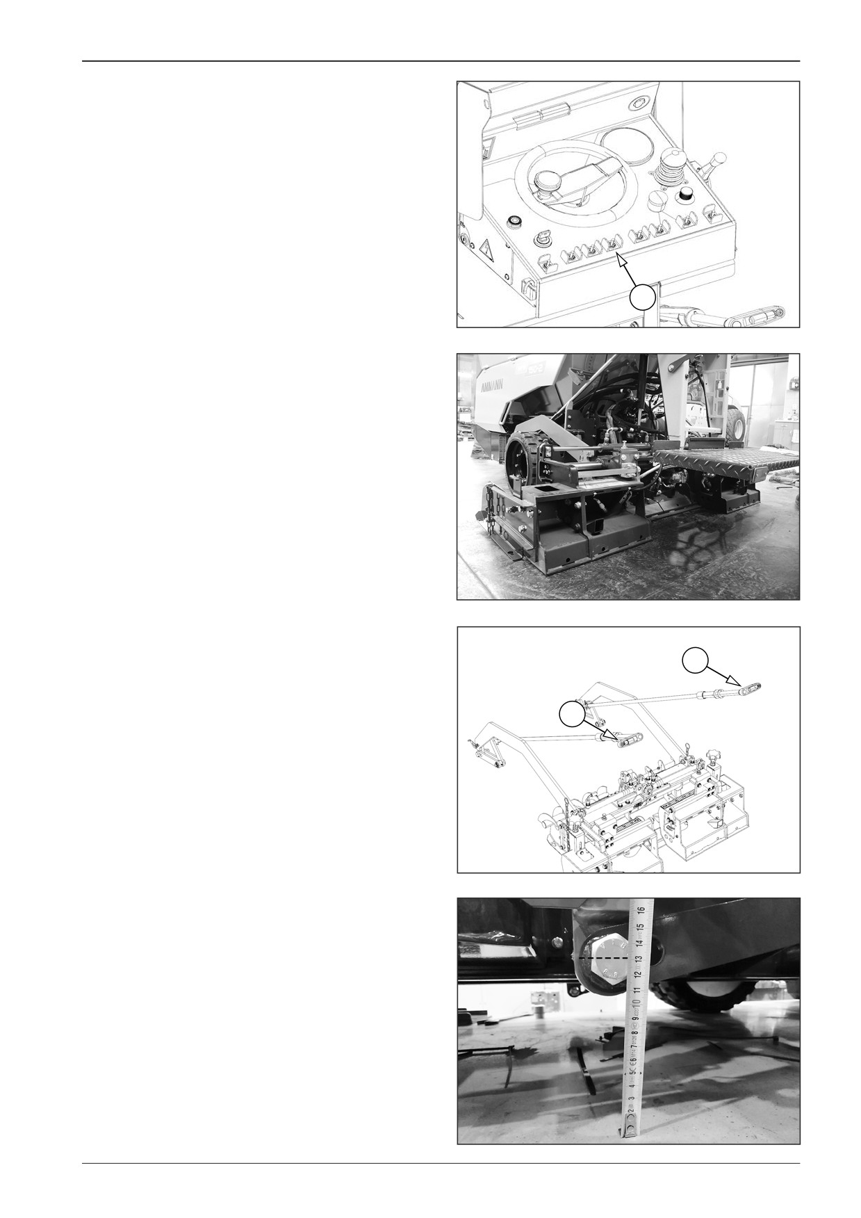
Start the engine and lower the screed to the ground by selector
switch (19).
19
451087B
D451606
Set the distance of 13-13.5 cm from the ground to the screw
centre by the paving thickness controller (47) on both sides.
47
47
451092
DD451035
F80W
125
12
Screed
Note
Ensure that the paving thickness controllers (47) face to the
ground on both sides.
47
47
DD451036
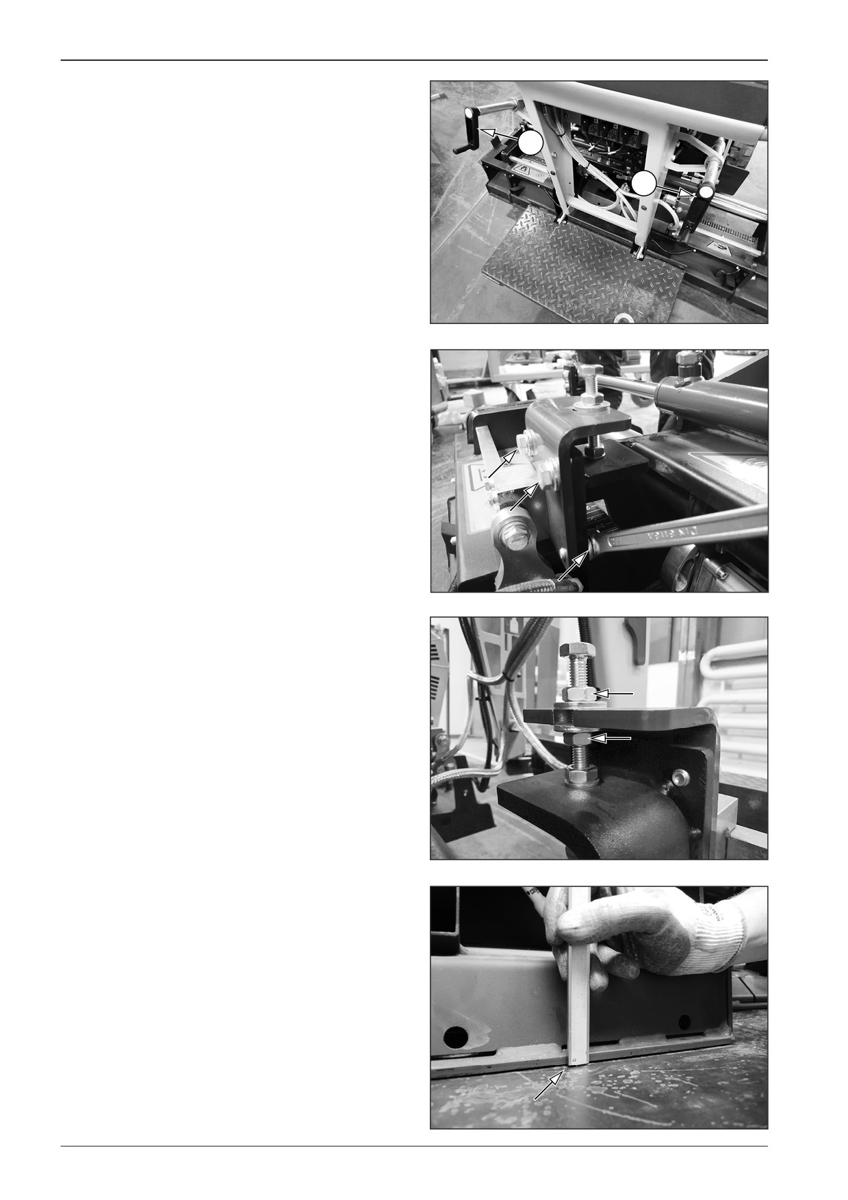
Loosen the screws (3x).
D451608
Using the adjusting nuts, set the height of the hydraulic exten-
sion to 2 mm above the main screed.
Lock the screws (3x).
DD451037
D451609
126
F80W
WORKSHOP MANUAL
13
Screed gas heating
F80W
127
13
Screed gas heating
10
2
12 V
5 A
12
7
11
2
1
1
1
6
4
3
5
8
3
4
3
9
8
D451900
13.1
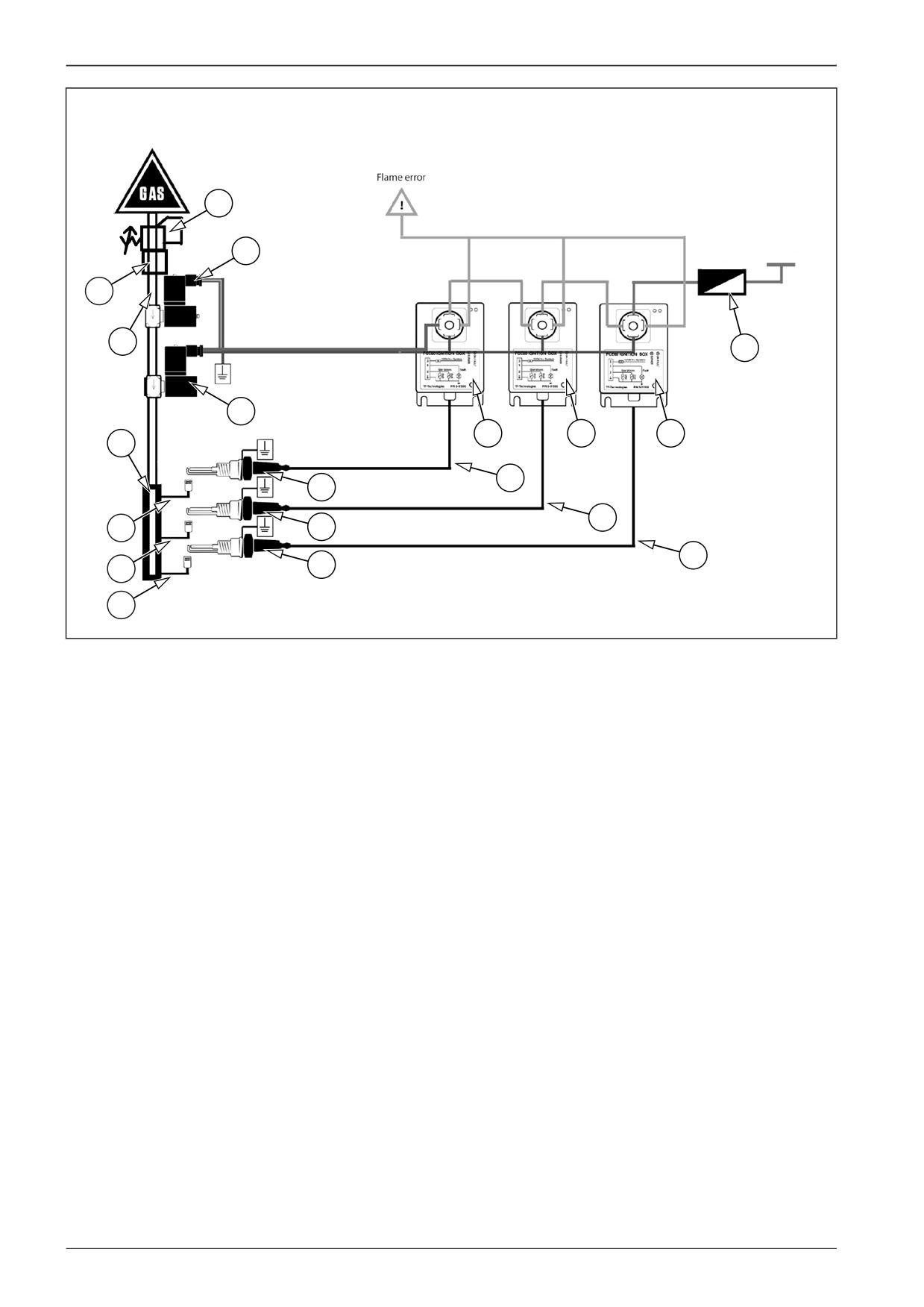
Gas system diagram
Legend:
1
Screed heating system ignition units
2
Gas supply solenoid valves
3
Spark plugs
4
Cables
5
Cable
6
Gas supply manifold
7
Gas hose
8
Gas hose
9
Gas hose
10
Reducing valve
11
Screed heating fuse, 5 A
12
Safety valve
128
F80W
WORKSHOP MANUAL
13.2
Ignition process
When the screed heating switch is switched on:
•
The control unit opens solenoid valves to supply gas to the
burners.
1
•
The control unit activates ignition units and unless perma-
nent fire is achieved within 7 seconds, the electronic system
indicates a fault.
•
If everything is OK, gas is automatically ignited by spark
plugs. Whether or not the flame is burning is evaluated by
the ignition unit through the spark plugs. After reaching
the temperature of 120°C on the screed temperature sen-
sor, the heating is automatically interrupted. After reducing
the screed temperature, heating is automatically activated
D451627
by the control unit.
•
If the flame cannot be ignited for any reason, a red Led indi-
cator is turned on on the ignition unit for the relevant sec-
tion, and an error message is displayed on the display.
Error message on the display:
F75 - Left screed extension
2
F76 - Main screed
F77 - Right screed extension
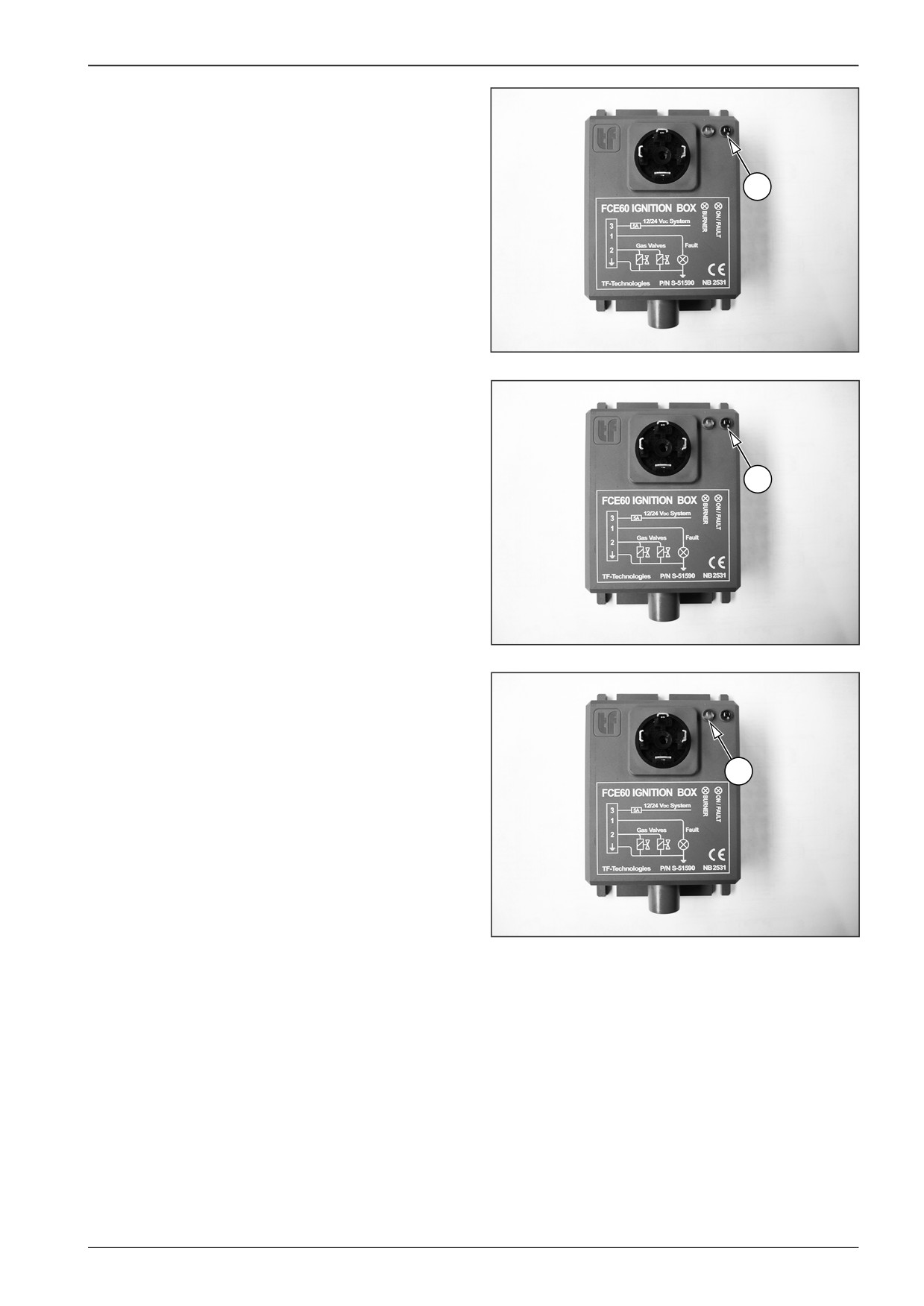
LED indicators on the ignition unit:
•
red LED indicator (1) - indicates a fault of the ignition system
for the given section
•
green LED indicator (2) - the ignition system is active
D451628
•
orange LED indicator (3) - is illuminated = it is burning, is not
illuminated = is not burning.
3
D451629
F80W
129