Dynapac Asphalt paver wheeled F80W Hatz. WORKSHOP MANUAL (2019) - page 1
F80W
Asphalt paver, wheeled
Hatz
Workshop manual
Edition 01/2019 EN
From Serial No. 4510125
Contents
Contents
2
1
INTRODUCTION
7
2
SAFETY MEASURES AND INSTRUCTIONS
11
2.1
Safety rules
12
2.2
Environmental and hygiene principles
15
2.3
Fire prevention
16
3
MACHINE DESCRIPTION
17
4
SPECIFICATION MANUAL
23
4.1
Basic data
24
4.2
Dimensional drawing of the machine
26
4.3
Technical data
28
4.4
Machine gradeability and lateral static stability of the machine
30
5
SPECIFICATION OF OPERATING FLUIDS
33
5.1
Engine oil
34
5.2
Fuel
34
5.3
Hydraulic oil
35
5.4
Anti-adherent solution
35
5.5
Liquid gas
36
5.6
Lubricating grease
36
5.7
Fluids
37
6
LUBRICATION AND MAINTENANCE CHART
39
7
ENGINE
43
7.1
Description of engine basic elements
44
7.2
Technical data of the manufacturer
46
7.3
Engine diagnostics
47
7.3.1
Measuring glow plug resistance
47
7.3.2
Measuring glow plug power supply
47
7.3.3
Measuring temperature sensor
48
7.3.4
Measuring lubricating oil pressure switch
49
7.3.5
Measuring extinguishing valve
50
7.3.6
Measuring engine speed
51
7.4
Dismounting the charging controller
52
7.5
Mounting the charging controller
53
7.6
Dismounting the engine
54
7.7
Mounting the engine
59
7.8
Engine speed adjustment
64
2
F80W
WORKSHOP MANUAL
8
STEERING
67
8.1
Description of basic elements
68
8.2
Technical data of the manufacturer
69
8.3
Diagnostics
69
8.4
Replacement of the gear pump
70
8.5
Dismounting the steering linear hydraulic motor
72
8.6
Mounting the steering linear hydraulic motor
74
8.7
Dismounting the steering unit
75
8.8
Removal of the hydraulic tank
76
8.9
Mounting the hydraulic tank
78
8.10
Adjustment of the front wheel turning angle indicator
79
9
TRAVEL
81
9.1
Description of basic elements
82
9.2
Diagnostics
85
9.2.1
Measuring the brake switch
85
9.2.2
Measuring the brake valve electromagnet Y7
86
9.2.3
Measuring the refilling pressure
87
9.2.4
Measuring the maximum pressure for forward and reverse travel
88
9.2.5
Measuring the resistance of the electromagnet coil
90
9.3
Removal of the travel pump
90
9.4
Dismounting the hydraulic motor and travel gearbox
92
9.5
Mounting the hydraulic motor and travel gearbox
94
10
GEAR PUMP
97
10.1
Description of basic elements
98
10.2
Diagnostics
100
10.2.1
Measuring the pressure of the belt conveyor and auger
100
10.2.2
Measuring the screed lifting pressure
101
10.2.3
Measuring the screed extension pressure
102
10.2.4
Measuring the maximum vibrator pressure
103
10.2.5
Measuring the vibration frequency
104
10.3.
Dismounting the gear pump
105
10.4
Dismounting the vibration units
106
10.5
Hydraulic system switchboard
108
10.5.1
Description of basic elements
108
11
COOLING
111
11.1
Description of basic elements
112
11.2
Cooling diagnostics
112
11.2.1
Fan test
112
11.2.2
Temperature sensor
112
11.3
Dismounting the cooler
113
11.4
Mounting the cooler
115
F80W
3
Contents
12
SCREED
119
12.1
Dismounting the screed lifting cylinder
120
12.2
Replacement of linear hydraulic motors for screed extension
122
12.3
Basic setting of the screed
124
13
SCREED GAS HEATING
127
13.1
Gas system diagram
128
13.2
Ignition process
129
13.3
Diagnostics
131
13.3.1
Gas equipment tightness check
131
13.4
Reducing valve
133
13.5
Gas hoses
133
13.6
Gas manifold
133
13.6.1
Gas manifold replacement
133
13.7
Screed heating burner
135
13.7.1
Screed heating burner replacement
135
13.7.2
Cleaning the gas burner nozzle
136
13.7.3
Gas flame adjustment
138
13.7.4
Test of burner ignition
139
13.8
Gas supply solenoid valves
141
13.8.1
Valve cleanliness inspection
141
13.8.2
Measuring resistance of the coils of gas supply valve electromagnets
142
13.8.3
Measuring power supply of the coils of gas supply valve electromagnets
143
13.9
Ignition units
144
13.9.1
Measuring resistance on the ignition unit
144
13.9.2
Voltage measurement on the cable harness of ignition units
145
13.10
High-voltage cables
146
13.11
Spark plugs
146
13.11.1
Spark plug function test
146
13.11.2
Spark plug check procedure
147
13.12
Temperature sensor
148
14
BELT CONVEYORS AND AUGERS
149
14.1
Replacement of the hydraulic motor for driving the augers and the belt conveyor
150
14.2
Dismounting the belt conveyor chain
153
14.3
Mounting the belt conveyor chain
157
14.4
Setting the belt conveyor chain sag
161
14.5
Dismounting the belt conveyor chain drive
163
14.6
Dismounting the auger chain
166
14.7
Replacement of the drive switch of augers and belt conveyor
169
14.7.1
Measuring the belt conveyor drive switch S7
170
14.8
Dismounting the driving gear wheel of augers
171
14.9
Replacement of consumables
172
14.9.1
Belt conveyor chain guide plate
172
14.9.2
Cover plates
178
4
F80W
WORKSHOP MANUAL
15
WIRING
179
15.1
Description of basic components
180
15.1.2
Central earthing points X6 and x7
181
15.2
Diagnostics
182
15.2.1
List of error codes displayed on the display
182
15.2.2
Fuse box
185
15.2.3
Diagnostics socket
186
15.2.3.1
Measuring of the CAN BUS data bus
187
15.2.3.1.1
Measuring voltage of the CAN BUS data bus
187
15.2.3.1.2
Measuring resistance of the CAN BUS data bus
187
15.2.4
Communication with the control unit A2 by means of Bodas - service 3.5
188
15.2.4.1
Connecting the machine to PC
188
15.2.4.2
Uploading and deleting errors
191
15.2.4.3
Check of parameters
192
15.2.5
Display measurement
193
15.2.6
Foot switch measurement
194
15.2.7
Travel controller measurement
195
15.2.8
Paving speed selector measurement
197
15.3
Calibration
200
15.3.1
Connecting the machine to PC
200
15.3.2
Calibration of the travel controller and the paving speed selector
201
15.3.3
Travel pump calibration
206
15.4
Control unit A2
213
15.4.1
Dismounting the control unit A2
213
15.5
Display unit
214
15.5.1
Dismounting the display
214
15.6
Travel controller
216
15.6.1
Dismounting the travel controller A4
216
15.7
Paving speed selector
218
15.7.1
Dismounting the paving speed selector
218
15.8
Battery
220
16
APPENDICES
221
16.1
Machine wiring diagram
222
16.2
Machine hydraulic system diagram
228
16.2.1
Measuring points of the hydraulic circuit
230
16.3
Screed gas heating system diagram
231
F80W
5
WORKSHOP MANUAL
1
Introduction
F80W
7

1
Introduction
The workshop manual is divided into separate chapters and contains technical and maintenance data, instructions for adjustment and
instructions for the use of special tools, jigs and aids.
The main purpose of this manual is to provide basic information for disassembly, assembly and service repairs of the main subassem-
blies of the machine.
Labelling of machine subassemblies in this manual corresponds to the spare parts catalogue.
In order to ensure smooth operation of the DYNAPAC compaction equipment, use only original spare parts supplied by DY-
NAPAC for repairs.
The manufacturer constantly improves its products on the basis of operational experience and the latest findings. Due to develop-
ment, the manufacturer reserves the right to change the images, descriptions, procedures and designs presented in this manual.
Before disassembly, it is recommended to always mark the removed parts for their reassembly and blank off all holes of
individual parts of the hydraulic system in order to prevent contamination of the hydraulic circuits.
When mounting individual parts on the machine, tighten individual screws or nuts according to the table of tightening
torques (see the appendix), unless specified otherwise in the text.
When handling the parts, use a crane and slings with adequate load capacity. Weights of individual parts are listed in
the electronic spare parts catalogue.
During work, always follow the safety instructions and measures given in Chapter 2.
8
F80W
WORKSHOP MANUAL
SAFETY NOTICES AND SIGNS:
The notice warns of a serious risk of personal injury or other personal hazards.
The notice warns of possible damage to the machine or its parts.
The notice warns of the necessity of environmental protection.
! CAUTION!
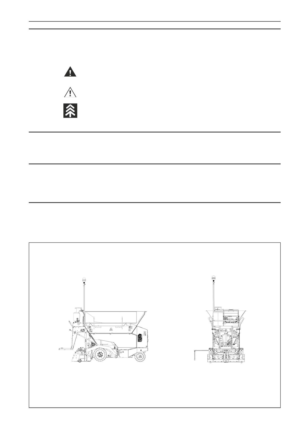
As used in this operating manual, the terms right, left, front and rear indicate sides of the machine moving forward.
UP
UP
REAR
FRONT
LEFT
RIGHT
DOWN
DOWN
D409002A
F80W
9
WORKSHOP MANUAL
2
Safety measures and instructions
F80W
11
2
Safety measures and instructions
2.1
Safety rules
These safety rules must be followed by all persons involved in machine repairs!
•
Repairs of this machine may be carried out only by qualified, professionally trained and experienced workers or by the Service
personnel of our dealers.
•
Always use our workshop manual when performing repairs. Individual chapters contain special instructions regarding assembly
work.
•
Before putting the machine into operation, familiarize yourself with the machine controls according to the Operating Manual and
make sure you have well understood all the equipment of your machine.
•
Do not use the machine if you do not fully understand all operating and control elements and if you do not know exactly how the
machine works.
•
Familiarize yourself with the area where you work.
•
Do not carry out any alterations or modifications to the machine, as this may affect the safety of the machine.
•
Original parts and accessories have been designed specifically for this machine.
•
Installation and use of spare parts that are not supplied or authorized by the machine manufacturer may have a negative impact
on the operational characteristics and safe operation of the machine.
•
It is forbidden to remove components of individual parts during the warranty period. If you fail to comply with this prohibition, the
warranty of the damaged component will not be recognized.
Safety measures for machine repairs and inspection
•
Wear work clothes and footwear.
•
Use gloves when handling oil, fuel and coolant.
•
When handling the battery, protect your eyes with goggles or a shield.
•
Place the machine on a level and firm surface before performing repairs. Secure the machine against spontaneous movement.
•
Secure the machine and drum frame against relative rotation with a lock pin and rod.
•
Before starting work, remove the key from the ignition, disconnect the batteries and allow hot parts to cool.
•
Attach a “machine out of order” sign to the steering wheel and leave it there for the duration of the work.
•
Properly wash the entire machine. In the case of steam cleaning, avoid aiming the steam flow directly at electrical components and
insulating material or cover them beforehand.
•
When removing, installing and repairing individual groups, maintain absolute cleanliness of all parts. Protect removed parts
against dirt.
•
Clean the surface of removed parts and create a corresponding dust-free work environment with the necessary storage area.
•
Handle cleaning agents with caution. Do not use petrol or other flammable substances for cleaning!
•
Dry the cleaned parts and immediately coat them with anti-corrosion oil - never install corroded parts!
•
Tools, lifting equipment, securing elements, supports and other auxiliary equipment must be in a good, working condition.
•
Lifting equipment and slings (ropes, chains) must have adequate load capacity and be intact.
•
Ensure sufficient air supply when starting the machine indoors.
•
Before putting the machine into operation, make sure there are no persons on the machine or in its dangerous proximity. Use the
audible warning signal when putting the machine into operation, always before starting the engine and after each break, before
the machine starts moving. Persons located on the machine and in its dangerous proximity must leave the machine and the area
after the audible warning signal.
•
Do not adjust the machine in operation.
•
When performing necessary work on a running engine (adjustment), avoid contact with hot and rotating parts of the machine.
Work performed when the engine is running (adjustment) must be carried out in the presence of another person who has immedi-
ate access to emergency shut-down and who is continuously in contact with the person performing the adjustment, so that the
engine can be immediately switched off if necessary.
•
Only use prescribed kinds of engine, transmission and hydraulic oil and coolant.
12
F80W
WORKSHOP MANUAL
Safety measures for work on hydraulic circuits
•
Before disassembly, make sure the hydraulic circuits are depressurized. Hydraulic oil leaking under pressure may damage your skin
and cause serious injury.
•
Before disassembly, mark the parts, hoses and pipes.
•
Do not put hydraulic pumps and motors into operation without oil.
•
Work with hot oil may result in scalding.
•
Do not heat the oil to temperatures above 160 °C - the oil or its vapours may ignite.
•
When removing hydraulic components, always blank off the hose ends and outlets of the components.
•
Use lint-free cloth when wiping and cleaning hydraulic parts.
•
When assembling parts, use hydraulic oil as a slip agent - not grease.
•
Before installation, carefully clean the fittings and flush and blow compressed air through hoses and pipes.
•
Only use new seals.
•
Fill new aggregates with hydraulic oil before installation.
•
After a hydraulic aggregate replacement, flush the hydraulic circuit and clean the hydraulic tank.
•
Replace the oil filter element.
•
Fill the hydraulic circuit with clean oil of prescribed viscosity, only when the engine is off!
•
Wipe any overflowed oil.
•
Check the connections for any leaks before the system pressurizes.
•
Check all connections after finishing all work.
•
Do not adjust safety valves.
•
After finishing work, reinstall all protective elements.
Check after putting into operation
•
Oil level in the hydraulic tank.
•
Check the charge pressure of replaced hydraulic pumps and the pressure of safety valves.
•
Perform the measurement at 40°C (104°F).
Safety measures for work on the fuel system
Petrol and diesel mixtures (winter fuel) are as flammable as petrol.
--
Do not refuel in enclosed spaces.
--
Wipe any overflowed fuel.
--
Do not smoke and do not use an open flame while working on the fuel system! There is a risk of fire!
F80W
13
2
Safety measures and instructions
Safety measures for work on the electrical system
•
Disconnect the battery when repairing the charging circuit to prevent accidental short circuits.
•
Before removal, disconnect the cable from the negative terminal (-) and then from the positive terminal (+).
•
Do not disconnect the batteries when the engine is running.
•
Connect the negative battery terminal to the ground and the positive terminal to the “B+” alternator output. The opposite connec-
tion would destroy the whole semiconductor equipment.
•
When starting using an auxiliary external power supply, do not disconnect this power supply until the machine battery is con-
nected. Pay attention to the starting voltage of the auxiliary external power supply (for 24 V).
•
Do not put the alternator into idle operation, i.e. with a disconnected wire from the “B+” terminal and connected “D+” terminal.
•
Do not check the presence of voltage in the wire by sparking against the machine frame.
•
Do not perform any activities generating sparks.
•
Use protective rubber gloves and eye protection when handling batteries.
•
Protect your skin and clothes against being splashed by the electrolyte or lead particles.
•
In case of eye contact with the electrolyte, immediately flush the affected eye thoroughly with running water for several minutes.
Then, seek medical treatment as soon as possible.
•
If the electrolyte comes in contact with skin or clothing, remove the clothes, immediately wash the affected areas with soapy water
or a solution of baking soda and water and seek medical treatment.
•
In case of ingestion of electrolyte, drink the maximum possible amount of milk, magnesium oxide dissolved in water or at least
water and immediately seek medical treatment.
•
Never fill the cells with distilled water, unless it is followed by work with the machine or recharging outside the machine. It would
otherwise cause excessive battery self-discharge.
•
Never fill up the acid (H2SO4)!
•
Do not turn over the batteries to avoid electrolyte flowing out of the degassing vents.
•
In case of acid (electrolyte) spillage, wash the affected area with water and neutralize with lime.
•
The charging process releases hydrogen, which forms an explosive, easily combustible mixture with air. Do not smoke or use open
flame or lights in the vicinity.
Welding work on the machine
•
Before performing welding work on the machine using an electric arc, disconnect all elements containing semiconductors from
the electrical system, including the machine electronics:
--
ground the power supply as well as the repaired machine,
--
protect the power supply against moisture,
--
place the ground terminal in close proximity to the weld joint,
--
When performing welding work on suspended parts or machine, it is necessary to prevent current from reaching the lifting
equipment by insulating the point of current transition or using non-conductive slings (hemp rope).
Sealing
•
Use new seals for all installation.
•
Seal kits are obtained as spare parts.
Tightening torques
•
In order to apply the correct tightening torque, use a torque spanner.
•
Fastening screws and nuts of used quality shall be tightened according to the respective tables.
•
The screw quality is indicated on the screw head.
•
Different tightening torques are specified in the respective chapters.
•
Threaded joints of hydraulic circuits shall be tightened according to the tables.
•
The presented tightening torques apply to non-lubricated threads.
•
Only use new self-locking nuts.
14
F80W
WORKSHOP MANUAL
2.2
Environmental and hygiene principles
When repairing the machines, observe general principles of health and environmental protection as well as laws and regulations re-
lated to this issue and being in force within the territory where the machine is used.
Hygienic principles
•
Petroleum products, fillings of cooling systems, battery fillings and paints, including thinners, are harmful substances that can
cause severe injuries when in contact with body organs.
•
It is therefore necessary to strictly follow safety and hygiene instructions of products and use personal protective equipment when
handling these substances.
•
Workers coming into contact with the above products when repairing the machine are obliged to follow general principles of their
own health protection and comply with safety and hygiene manuals of the manufacturers of the products.
In particular we draw your attention to the following:
--
Protect your eyes and skin while working with the batteries.
--
Protect your skin while handling petroleum products, coating compounds and coolants.
--
Wash your hands properly after finishing the work and before eating, treat your hands with a suitable reparation cream.
--
When handling the cooling system, follow the instructions given in the manuals supplied with the machine.
•
Always store petroleum products, cooling system fluids, battery fluids and coating compounds including thinners and also clean-
ers and preservative agents in their original and properly labelled containers. These materials are not allowed to be stored in unla-
belled bottles or in any other containers considering the likelihood of confusion. Possible confusion with foodstuffs or beverages
is very dangerous.
•
If by accident the skin, eyes or mucous membrane is stained or if you breathe in the vapours of such products, apply immediately
the principles of the first aid. In case of accidental ingestion of these products, immediately seek medical help.
Environmental measures
•
Discarded operating fluids of individual systems of the machine and also some of its parts become hazardous wastes with danger-
ous properties for the environment.
This category of waste products includes in particular:
--
organic and synthetic lubricating materials, oils and fuels;
--
coolants;
--
battery cartridges and batteries;
--
cleaning and preservative agents;
--
all dismounted filters and filter elements,
--
all used and discarded hydraulic or fuel hoses, rubber-metals and other parts of the machine contaminated by the above
mentioned products.
•
It is necessary to treat the above mentioned materials and parts after they have been discarded in accordance with relevant na-
tional regulations valid for protection of individual parts of the environment and in compliance with health protection regulations.
•
When disassembling hydraulic, fuel and cooling systems and their units. Escape of fluids into the ground has to be prevented by
using suitable vessels placed underneath and by plugging of the holes.
•
In case of leakage, the affected area must be immediately dried with the use of sawdust, Vapex, etc.
•
The affected soil must be removed to prevent further leakage. The contaminated soil and absorbent should then be handed over
for further safe disposal.
F80W
15
2
Safety measures and instructions
2.3
Fire prevention
•
The oil change area must be located so that it does not interfere with any explosion or fire hazard area.
•
It must be identified by the tables and marks with “No smoking” signs and signs prohibiting the use of naked fire.
•
The handling area must be dimensioned so that it can capture a volume of the flammable liquid equal to the capacity of the big-
gest transport container.
•
It must be equipped with portable fire extinguishers.
•
For handling the oil and diesel fuel, use such vessels as metal barrels, jerry cans, sheet-metal cans.
•
The transport containers must be properly closed during storage.
•
Vessels must be with only one outlet, stored always with the outlet up and secured against the outflow and drains.
•
Containers must be marked by non-removable texts stating the contents and flammability classes.
Special tools, jigs - see relevant chapters of the manual
16
F80W
WORKSHOP MANUAL
3
Machine description
F80W
17
3
Machine description
11
36
13
14
21
30
18
4
6
12
2
10
20
3
8
7
23
29
28
9
22
34
27
1
2
3
15
33
17
19
16
31
32
D451032B
18
F80W
WORKSHOP MANUAL
Legend:
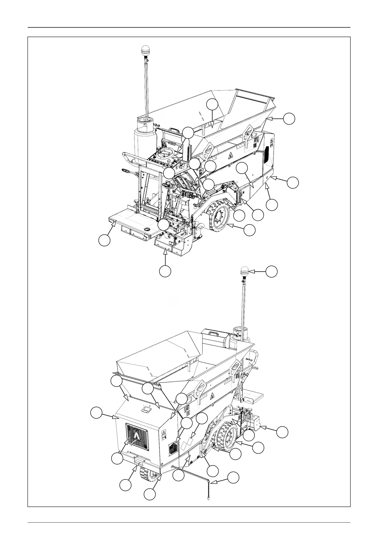
1. Augers
2. Screed tow arm
3. Travel wheels
4. Machine frame
5. Belt conveyors
6. Screed lock
7. Screed
8. Tilting platform
9. Engine
10. Paving thickness indicator
11. Hopper
12. Exhaust
13. Main dashboard
14. Steering wheel
15. Tow point
16. Paving direction indicator
17. Battery disconnecter
18. Conveyor hydraulic motor
19. Battery
20. Screed linear hydraulic motor
21. Material outlet
22. Hydraulic pumps
23. Beacon
24. Gas bottle
25. Fuse box
26. Warning horn
27. Air filter
28. Fuel tank
29. Bonnet
30. Hydraulic tank
31. Lug for towing the machine
32. Conveyor tensioner
33. Combined cooler
34. Storage space for the first aid kit
35. Mounting place for a manual fire extinguisher.
36. Hopper extension
F80W
19
3
Machine description
47
47
45
39
38
45
40
41
46
40
52
44
41
51
42
37
41
39
46
37
43
451033B
49
50
48
D451032C
20
F80W
WORKSHOP MANUAL
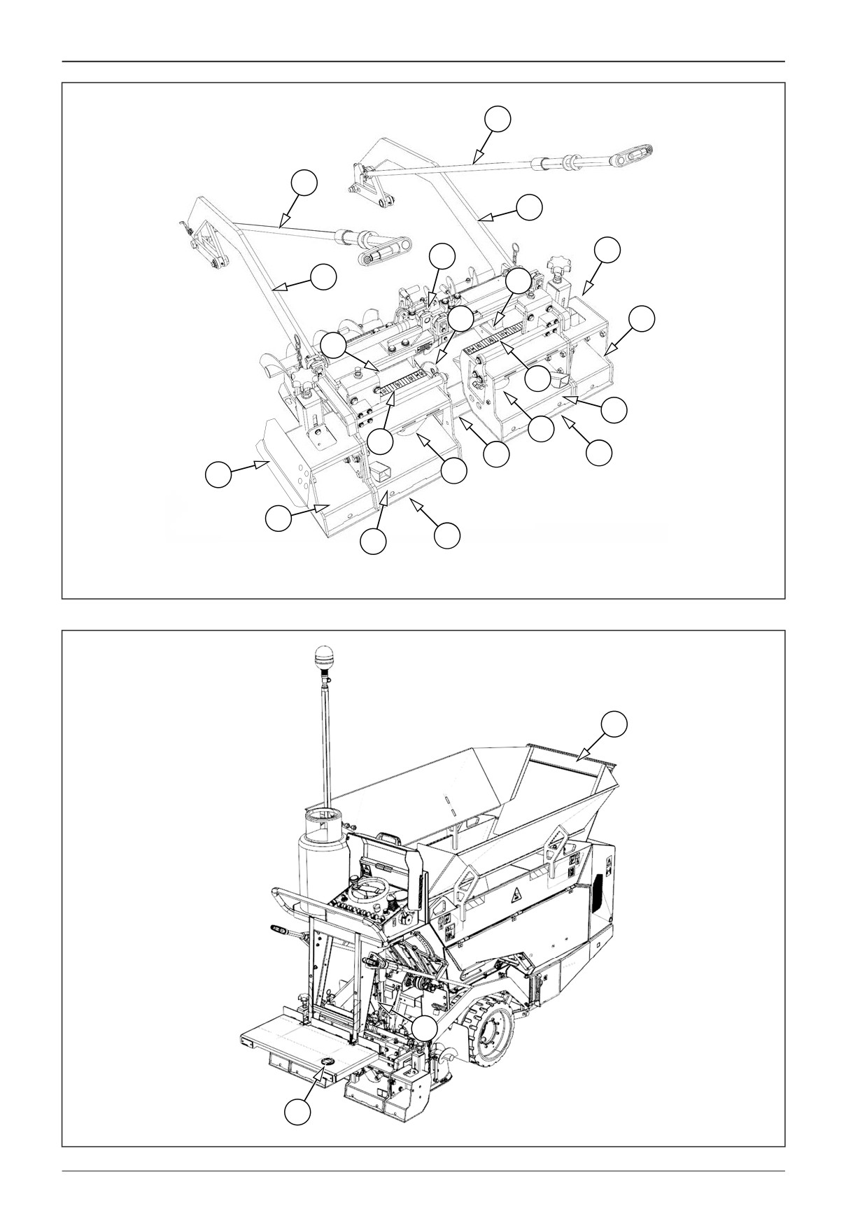
37. Roadway profile bottom plates
38. Crown adjustment
39. Screed end gate
40. Screed vibrators
41. Gas components
42. Main screed
43. Left screed extension
44. Right screed extension
45. Screed tow arm
46. Mechanical extension
47. Paving thickness controller
48. Foot switch
49. Hopper cover
50. Conveyor limit switch
51. Left indicator of paving width setting
52. Right indicator of paving width setting
F80W
21
WORKSHOP MANUAL
4
Specification manual
F80W
23
4
Specification manual
4.1
Basic data
Machine type
Machine description
The F80W wheeled asphalt paver is equipped with a screed with
gas heating. The basic paving width is from 800 mm (31.5 in) to
Serial number of the machine
1,300 mm (51.2 in).
The machine is characterised with good manoeuvrability, good
view from the operator's place, a wide range of uses and easy
Year of manufacture
transport.
Specification of the expected use of the machine
Engine type
The performance and dimensions of the F80W wheeled asphalt
paver predetermine it for a wide range of paving works, in par-
ticular for city streets, city centres as well as for repairs and gen-
eral maintenance of constructions.
Serial number of the engine
The F80W wheeled asphalt paver has been designed and manu-
factured for the use for:
Paving asphalt mixtures (at hot condition)
Screed type
Paving loose mixtures (at cold condition)
Serial number of the screed
The machine is not intended for paving concrete.
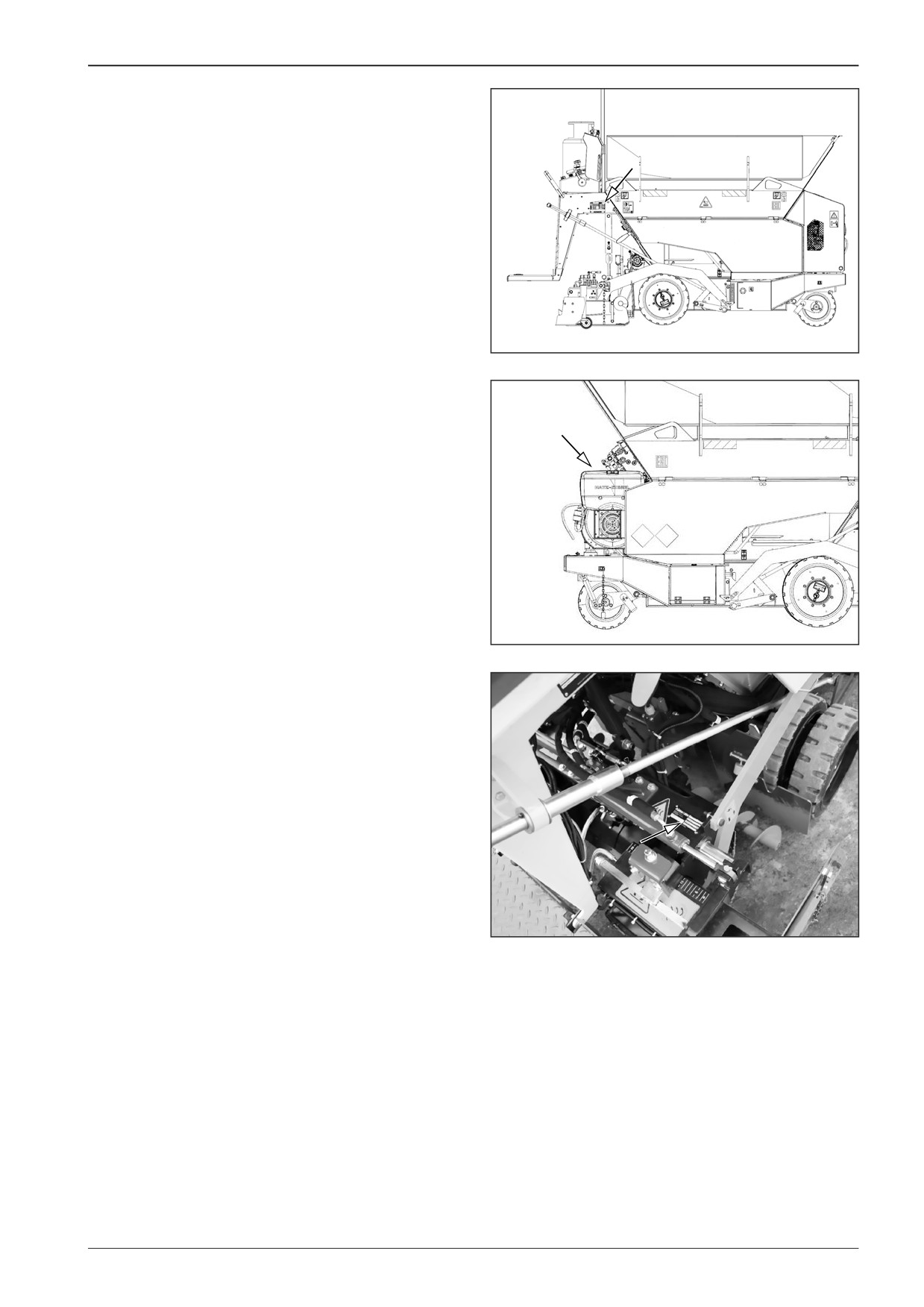
The machine that complies with the requirements on health
protection and safety is provided with a nameplate with CE
marking.
AMMERLAENDER STR. 93
D-26203 WARDENBURG
GERMANY
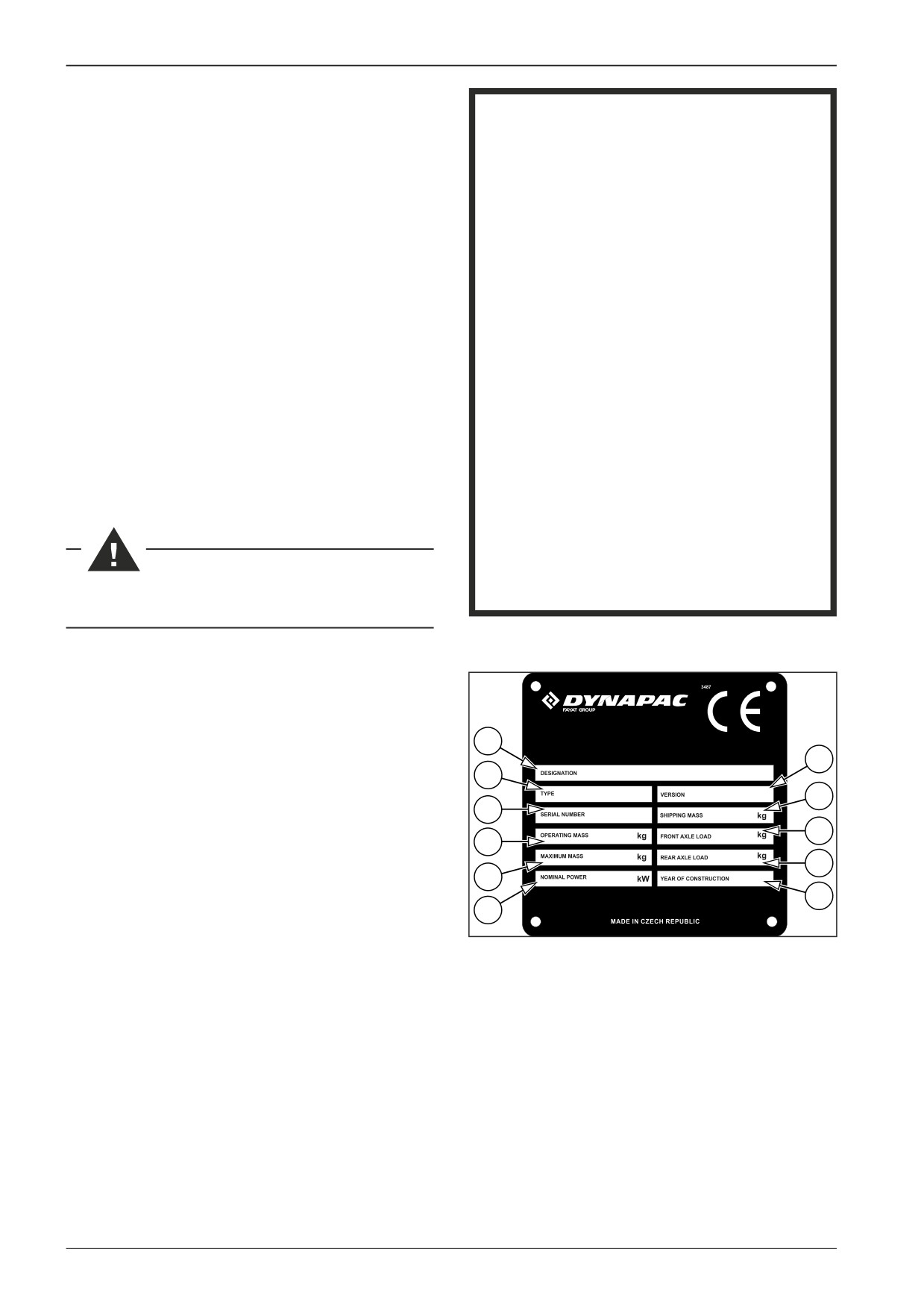
1
1. Name - always stated only in the English version
7
2. Type
2
3. Serial number
8
3
4. Operating weight
5. Maximum mass
9
4
6. Rated power
10
7. Version
5
8. Transport weight
11
9. Front axle load
6
10. Rear axle load
D3487
11. Year of manufacture
24
F80W
WORKSHOP MANUAL
Nameplate.
Serial number of the machine.
D451023
Serial number of the engine.
D451024
Nameplate of the screed.
Serial number of the screed.
D451025A
F80W
25
4
Specification manual
4.2
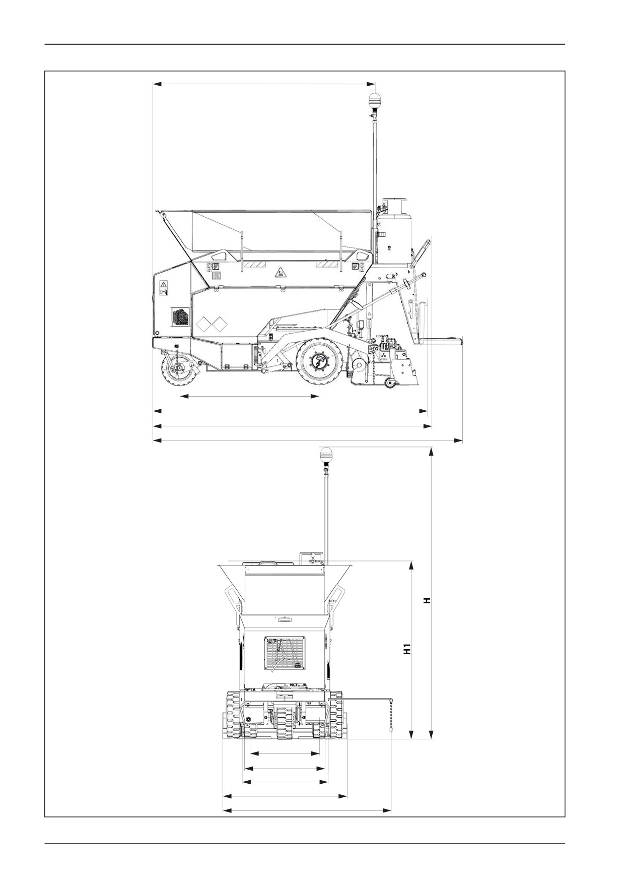
Dimensional drawing of the machine
B
A
L1
L2
L
W1
W
W2
W3
W4
D451170A
26
F80W

WORKSHOP MANUAL
A
B
H
H1
L
L1
mm
1280
2070
2680
1598
2865
2526
in
50.4
81.5
105.5
62.9
112.8
99.4
L2
W
W1
W2
W3
W4
mm
2550
765
640
800
1150
1699
in
100.4
30.1
25.2
31.5
45.3
66.9
F80W
27

4
Specification manual
4.3
Technical data
Weight
The machine operation weight (including: screed extension, doubled driving wheels, vibration)
kg (lb)
1260 (2780)
Transport weight
kg (lb)
1185 (2610)
Driving characteristics
Number of speeds
-
2
Working speed
km/h (MPH)
0.6
(0.37)
Transport speed
km/h (MPH)
2.5
(1.6)
Machine gradeability with an empty hopper (screed in the lower position)
° / %
7 / 12
Machine gradeability with a full hopper (screed in the lower position)
° / %
11 / 19
Machine descent with a full hopper (screed in the lower position)
° / %
20 / 36
Lateral static stability with an empty hopper
° / %
12 / 21
Lateral static stability with a full hopper
° / %
12 / 21
Drive type
-
Hydrostatic
Number of driving axles
-
1
Steering
Steering type
-
Hydraulic
Hydraulic servo
Steering control
-
unit
Engine
Manufacturer
-
Hatz
Type
-
1B40T
Power according to ISO 3046-1
kW (HP)
6.3 (8)
Number of cylinders
-
1
Cylinder capacity
cm3 (cu in)
462 (28)
Nominal speed
min-1 (RPM)
2600
Maximum torque
Nm/rpm
25/2000
The engine complies with emission regulations
-
Not regulated
Engine cooling system
-
Air-cooled
Axle
Number of tyres
-
2
Rear wheel
-
432/127
Front wheel
-
330/152
Brakes
Operating
-
Hydrostatic
Parking
-
Mechanical
28
F80W

WORKSHOP MANUAL
Operating fluids
Fuel
l (gal US)
5 (1.3)
Engine (oil filling)
l (gal US)
1.8
(0.5)
Hydraulic system
l (gal US)
20 (5.3)
Lubricants
kg (lb)
0.1
(0.22)
Gas bottle with the maximum volume
kg (lb)
10 (22)
Maximum operating pressure
bar
1
Recommended operating pressure
bar
0.6-0.8
Propane-butane
Gas type
-
(LPG)
Hopper
Hopper capacity
kg (lb) / m3
1,600 (3,527) / 0.6
Filling area length
mm (in)
1100 (43.3)
Paving
Paving capacity
kg/h (lb/h)
22,000 (48,500)
Paving thickness
mm (in)
5-100 (0.2-3.9)
Screed
Minimum paving width without reduction plates (standard equipment of the machine)
mm (in)
800 (31.5)
Maximum paving width without reduction plates (standard equipment of the machine)
mm (in)
1300 (51.2)
Minimum paving width with reduction plates
mm (in)
250 (9.8)
Maximum paving width with reduction plates
mm (in)
750 (29.5)
Minimum paving width with mechanical extension
mm (in)
1150 (45.3)
Maximum paving width with mechanical extension
mm (in)
1650 (65)
Electrical installation
Voltage
V
12
Battery capacity
Ah
55
Noise and vibration emissions
Measured sound power level A, LpA at the operator platform*
dB
81
Uncertainty KpA *
dB
2
Guaranteed sound power level A, LWA **
dB
104
Declared highest weighted effective value of vibration acceleration transmitted to the whole
m/s2 (ft/s2)
0.6
body (platform)***
Declared total value of vibration acceleration transmitted to hands (platform)***
m/s2 (ft/s2)
<2.5
* measured according to EN 500-4
** measured according to DIRECTIVE 2000/14/EC
*** measured according to EN 1032+A1 while driving with vibration on gravel foundation
F80W
29
4
Specification manual
4.4
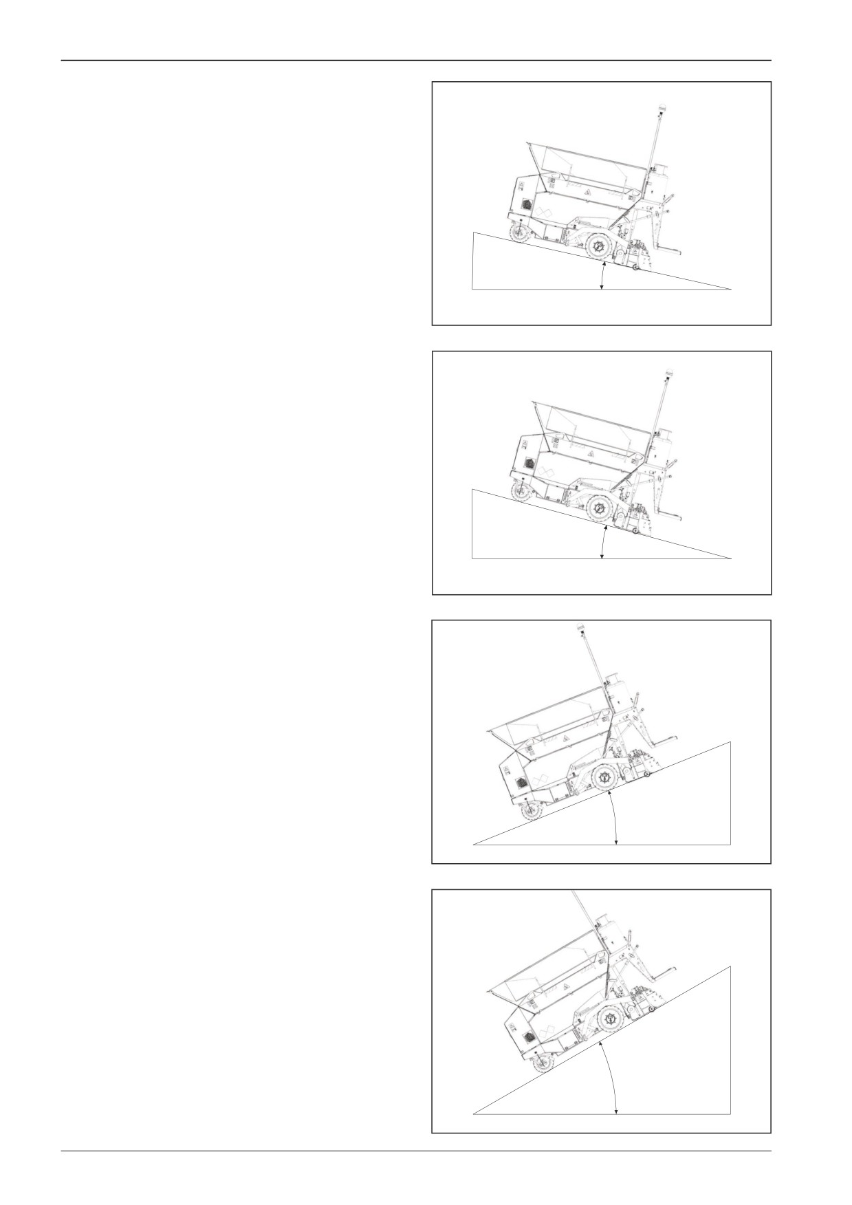
Machine gradeability and lateral static
stability of the machine
Machine gradeability with an empty hopper (screed in the lower
position).
α = 7° (12%)
D451171
Machine gradeability with a full hopper (screed in the lower po-
sition).
α = 11° (19%)
D451172
Machine descent with an empty hopper (screed in the lower
position).
α = 12° (21%)
D451174
Machine descent with a full hopper (screed in the lower posi-
tion).
α = 20° (36%)
D451173
30
F80W

WORKSHOP MANUAL
Lateral static stability with an empty and full hopper.
α = 12° (21%)
D451175
F80W
31
WORKSHOP MANUAL
5
Specification of operating fluids
F80W
33

5
Specification of operating fluids
5.1
Engine oil
5.2
Fuel
2412
Engine oil has been specified as per its performance classifica-
Diesel oil is used as fuel for the engine:
tion and viscosity classification.
•
EN 590
•
BS 2869 A1 / A2
Performance classification according to
•
ASTM D 975-09a 1-D, 2-D
API (AMERICAN PETROLEUM INSTITUTE)
ACEA (ASSOTIATION DES CONSTRUCTEUERS EUROPPÉENS DE
At ambient temperatures below 0°C (32°F), use winter diesel
AUTOMOBILE)
fuel.
Mixing diesel with special additives is forbidden.
Viscosity classification
Mixing diesel with petrol is forbidden.
To determine the SAE (Society of Automotive Engineers) viscos-
ity class, the ambient temperature and type of operation where
the machine is used are decisive.
Use of permissible oils according to API: CF / CH-4 or better quality.
Use of permissible oils according to ACEA: B3 / E4 or better quality.
SAE 15W-40 year-round.
Note
Exceeding the lower temperature limit does not result in dam-
age to the engine; it can only cause some starting difficulties.
It is convenient to use universal multi-range oils to avoid oil
changes due to ambient temperature.
For easy starts at the temperatures below 0°C (32°F), the engine
manufacturer recommends SAE 10W-30 oil.
Exceeding the upper temperature limit, considering the
reduced lubricating capabilities of the oil must not last
for long.
34
F80W
WORKSHOP MANUAL
5.3
Hydraulic oil
5.4
Anti-adherent solution
2158
AMN411
For the hydraulic system of the machine, it is necessary to use
The anti-adhesive liquid is a non-adhesive additive.
only high-quality hydraulic oil grades according to ISO 6743/HV
It serves for cleaning the hopper, conveyor, augers and parts of
(equal to DIN 51524 part 3 HVLP).
the machine which are in contact with the paved asphalt mate-
Fill the Machines normally with hydraulic oil that has cinematic
rial.
viscosity of 46 mm2/s at 40°C (104°F) ISO VG 46. This oil is the
most suitable for use in the widest range of ambient tempera-
tures.
Use an environmentally-friendly anti-adherent solution accord-
ing to the applicable national regulations.
To create the anti-adherent solution, mix a non-sticking agent
Synthetic hydraulic oil
with water according to the instructions of the non-sticking
The hydraulic system can be filled with synthetic oil, which if
agent manufacturer.
leakages occur will be degraded completely by micro-organ-
isms present in water and soil.
Dosage
The anti-adherent solution dosage may vary depending on the
operating conditions:
For standard mixtures, 1 part of anti-adherent solution in 30
parts of water. (1:30)
Always consult with the oil manufacturer or dealer any
For modified mixtures, 1 part of anti adherent solution in 5 parts
switching from mineral oil to synthetic or mixing oils of
of water. (1:5)
various brands!
Note
There is no vessel for an anti-adherent solution on the machine.
To apply the anti-adherent solution on individual parts of the
machine, use a hand pump for spraying liquids.
It is prohibited to use diesel oil instead of an anti-adher-
ent solution.
F80W
35

5
Specification of operating fluids
5.5
Liquid gas
5.6
Lubricating grease
0787
The machine is equipped with a gas heating system that uses
To lubricate the machine you must use a plastic grease contain-
liquid gas as fuel.
ing lithium according to:
•
Propane-butane (LPG)
ISO 6743/9 CCEB 2
DIN 51 502 KP2K-30
Propane-butane (LPG) is an extremely flammable substance
and any leakage causes a high risk of fire or explosion!
Propane-butane (LPG) is heavier than air and may accumu-
late in lower places - danger of fire or explosion!
Gas inhalation may cause headache, weakness, confusion,
dizziness and nausea. It causes frostbites in the liquid state
in contact with skin!
Avoid contact with skin. Wear suitable protective clothing!
Wear protective gloves resistant to oil substances comply-
ing with EN374!
Wear safety goggles!
In case of excess of vapour concentration limits in air, use
a suitable breathing mask. Recommended: organic fume
and vapour filter (type A, AX)!
No smoking at work.
Provide adequate area ventilation!
Always require a material safety data sheet to the delivered
gas bottle. Before mounting the gas bottle on the machine,
read and check that the gas bottle meets all conditions for
putting the machine into operation.
The machine must be equipped with a fire extinguisher.
Have the fire extinguisher ready on the driver's stand at
a place intended for this purpose.
When the machine is operated in underground garages or
other underground areas, observe the national safety regu-
lations regarding space ventilation.
Stop the gas leakage.
In case of gas leakage, inform relevant national authori-
ties.
36
F80W

WORKSHOP MANUAL
5.7
Fluids
Filling quantity
Part
Fluid type
Brand
l (gal US)
Engine
Engine oil according to Chapter 5.1.
1.8 l (0.48 gal US)
2412
Fuel tank
Fuel according to Chapter 5.2.
5 l (1.3 gal US)
Hydraulic system
Hydraulic oil according to Chapter 5.3.
20 l (5.3 gal US)
2158
Maximum weight of 10 kg
Liquid gas
Liquid gas according to Chapter 5.5.
(22 lb)
Anti-adherent solution
Fluid according to Chapter 5.4.
-
AMN411
Lubricating grease
Grease according to Chapter 5.6.
As required
0787
F80W
37
WORKSHOP MANUAL
6
Lubrication and maintenance
chart
F80W
39

6
Lubrication and maintenance chart
Every 10 hours at the beginning of work (daily)
Fuel level check
Engine oil level check
Hydraulic tank oil level check
Driver's stand cleaning
Cleaning the hopper, outlets and conveyor
Cleaning the augers
Test of burner ignition, flame position adjustment and spark plug maintenance
Gas equipment tightness check
Every 10 hours at the end of work (daily)
Fuel level check
Cleaning the conveyor
Cleaning the augers
Every 50 hours (weekly)
Clearing the water separator
Machine lubrication
After 50 hours of operation
Engine oil replacement
Every 100 hours of operation (monthly)
Fuel system tightness check
Rear wheel fastening check
Conveyor chain tension
Every 250 hours of operation (every 3 months)
Engine oil replacement
Engine air intake check
Engine accelerator cable tension check
Hydraulic oil cooler cleaning
Hydraulic circuit tightness check
Battery inspection
40
F80W
WORKSHOP MANUAL
Every 500 hours of operation (every 6 months)
Fuel filter replacement
Air filter replacement
Front and rear wheel condition check
After 500 hours of operation
Hydraulic oil and hydraulic oil filter replacement **
Every 1000 hours (yearly)
Engine oil filter cleaning
Hydraulic oil and hydraulic oil filter replacement **
Gas line hose replacement
Maintenance as required
Battery replacement
Screw connections tightness check
* First after 50 engine hours.
** First after 500 engine hours.
F80W
41
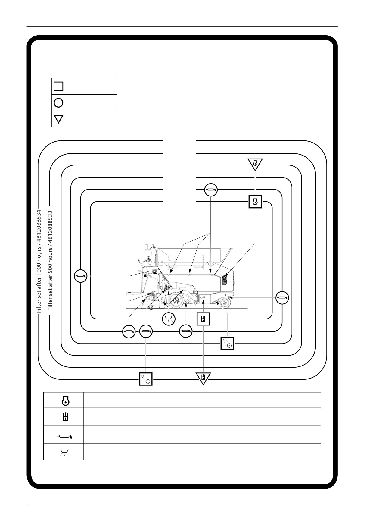
6
Lubrication and maintenance chart
LUBRICATION AND SERVICE PLAN
INSPECTION
LUBRICATION
REPLACEMENT
1000
500
250
100
50
10
Engine oil:
SAE 15W-40
API CF / CH-4
Hydraulic oil:
ISO VG 46
ISO 6743/HV
Lubricating grease:
ISO 6743/9
CCEB 2
Specification according to the coun-
Anti-adherent solution:
try of machine operation
D451351B
42
F80W
WORKSHOP MANUAL
7
Engine
F80W
43
7
Engine
7.1
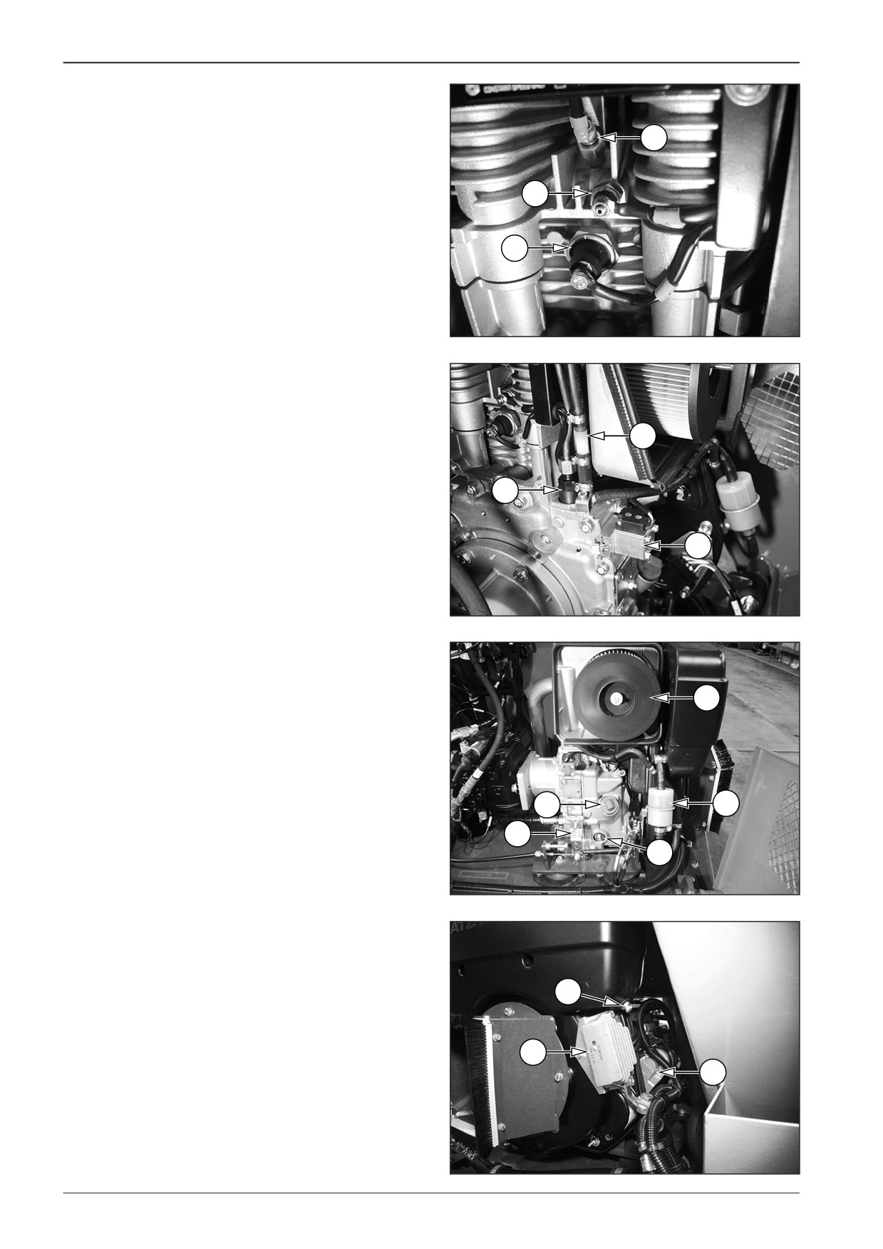
Description of engine basic elements
1
Glow plug
1
2
Temperature sensor
3
Lubricating oil pressure switch
2
3
451400
4
One-way valve
5
High-pressure pump
6
Extinguishing valve
4
5
6
D451401
7
Air filter
8
Oil dipstick
9
Oil filter
7
10 Speed adjustment lever
11 Fuel filter
8
11
10
9
D451402
12 Condensate drain
13 Charging controller
14 Starter
12
13
14
D451403
44
F80W
//////////////////////////////////////////