Dynapac Asphalt paver wheeled F80W Hatz. WORKSHOP MANUAL (2019) - page 2
WORKSHOP MANUAL
15 Fuel tank
15
D451404
F80W
45

7
Engine
7.2
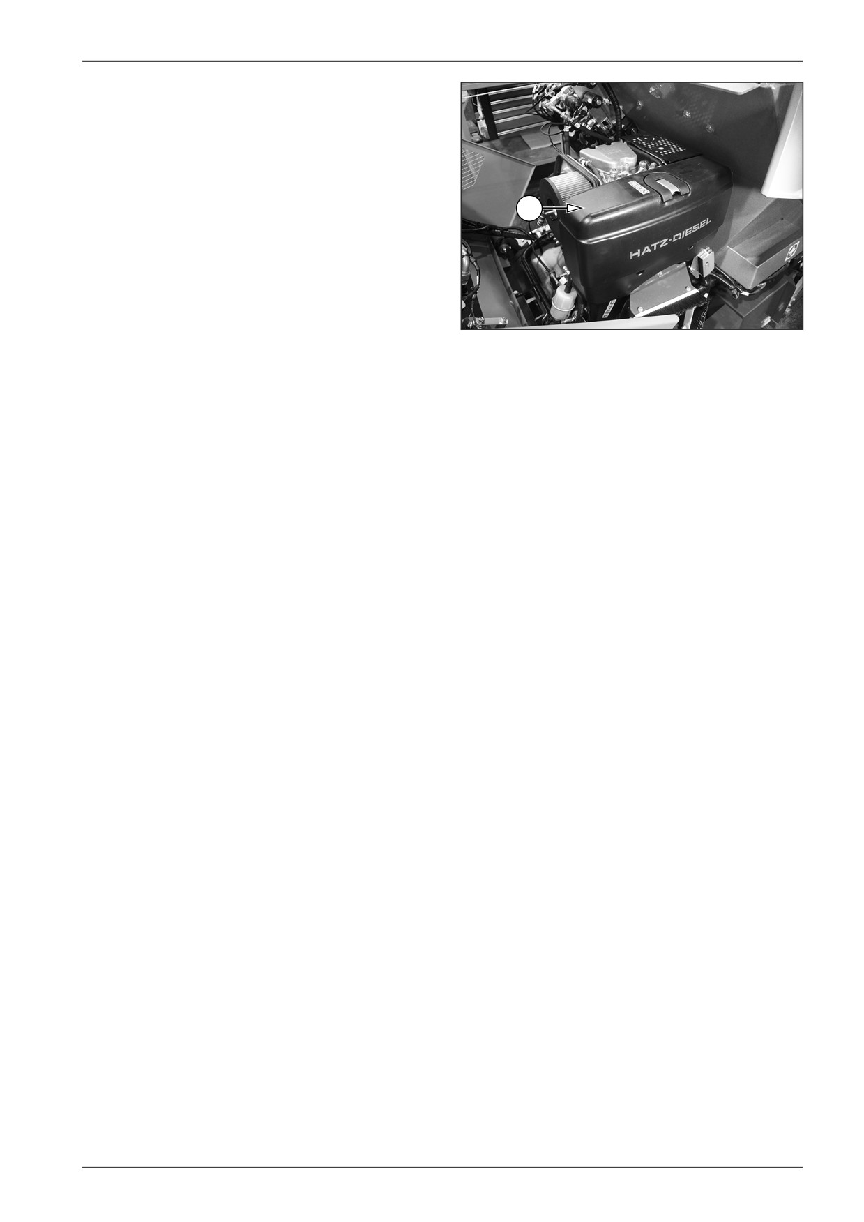
Technical data of the manufacturer
General technical data
Engine type
1B40T
Working principle
Air-cooled four-stroke diesel engine
Combustion process
Direct injection
Number of cylinders
1
Bore/stroke
88/76 mm (3.46/2.99 in)
Total volume of cylinders
462 cm3
Tank capacity
5 l (1.32 gal US)
Engine oil capacity without an oil collector
1.5 l (0.4 gal US)*
Engine oil capacity with an oil collector
3.2 l (0.85 gal US)*
Difference between the minimum and maximum marking
0.8 l (0.21 gal US)*
without an oil collector
Difference between the minimum and maximum marking with
2.2 l (0.58 gal US)*
an oil collector
Engine oil consumption
Max. 1% of fuel consumption, referred to the full load
Oil pressure at 100°C
Approximately 2.5 bar at 3000 rpm
Direction of rotation when looking at the flywheel
Left
Valve clearance at 10-30°C
0.10 mm (0.0039 in)
Maximum allowed inclination during operation in the given
Flywheel side 25°C **
direction
Other directions 35°C **
Weight (including the fuel tank, air filter, damper and electric
Approximately 55 kg (121.25 lb)
start)
Battery capacity
Min. 12 V - 36/55 Ah
Max. 24 V - 24/44 Ah
* These specifications are approximate values. The maximum marked value on the dipstick is always decisive.
** Exceeding these limit values will cause damage to the engine.
46
F80W
WORKSHOP MANUAL
7.3
Engine diagnostics
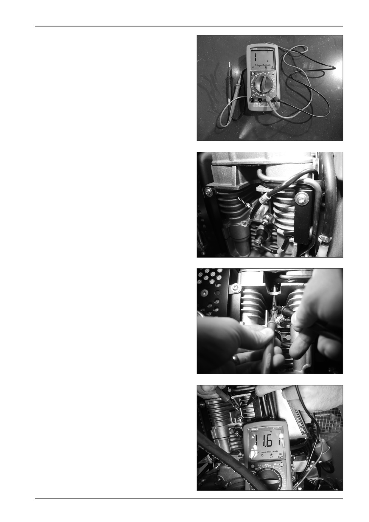
All measured values are measured using a multimeter.
D451405
7.3.1
Measuring glow plug resistance
Remove wire no. 6.
D451406
The measured resistance is approximately 0.9 Ω.
Note
In case of the measured value - open circuit, replace the glow
plug.
D451407
7.3.2
Measuring glow plug power supply
Measure voltage of approximately 12 V between wire no. 6 and
the engine frame with the engine pre-heating switched on.
D451408
F80W
47
7
Engine
7.3.3
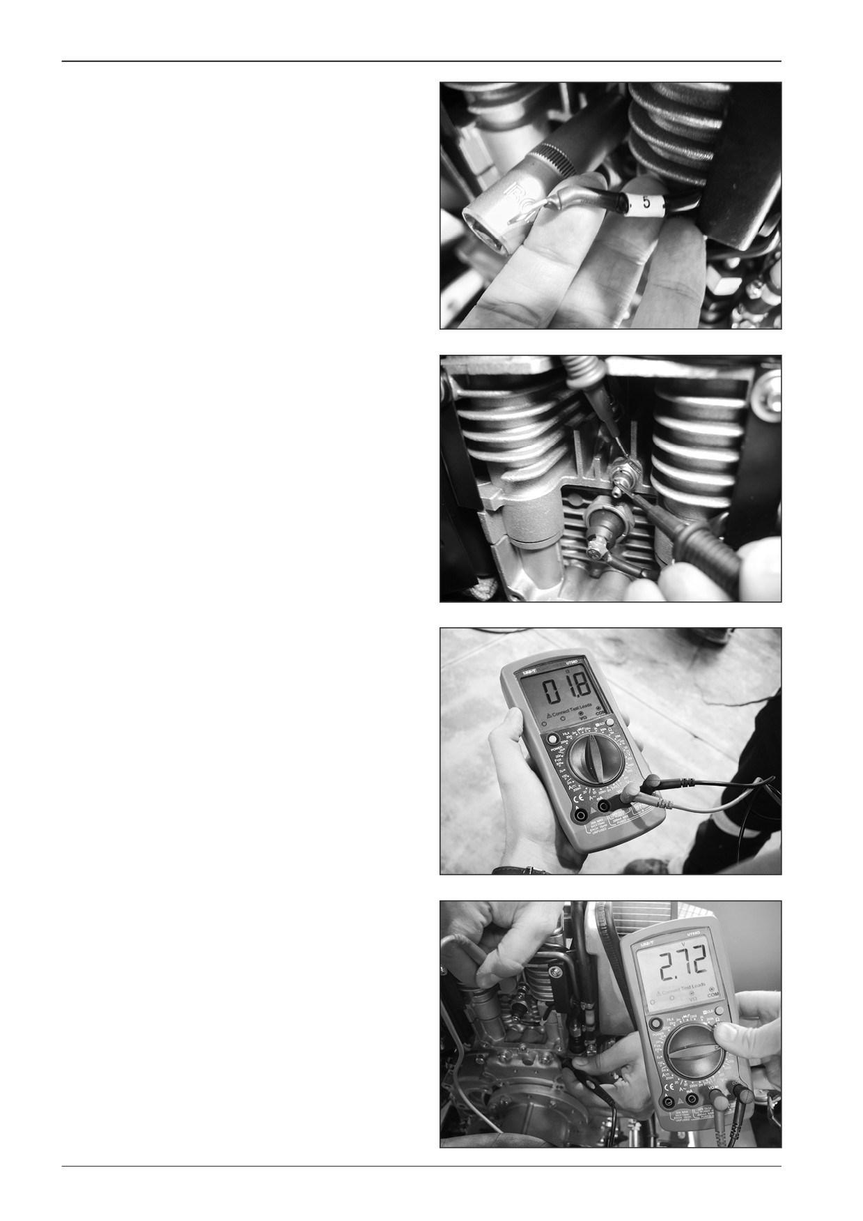
Measuring temperature sensor
Remove wire no. 5.
D451409
Measure the resistance between the engine frame and the con-
necting screw.
D451410
The switch is disconnected (the disconnected circuit). The
switch is connected at the temperature of 220°C and the resist-
ance is approximately 1.8 Ω.
D451411
Before measuring voltage make sure that the key in ignition is in the
“I” position.
The voltage between wire no. 5 and the engine frame is approxi-
mately 2.7 V.
Note
The measured value must be approximately 1.8 Ω at the engine
temperature of 220°C. If disconnected circuit is measured, re-
place the switch.
To verify the function
When the engine is overheated, attach wire no. 5 to the engine
frame and the fan must start up.
D451412
48
F80W
WORKSHOP MANUAL
7.3.4
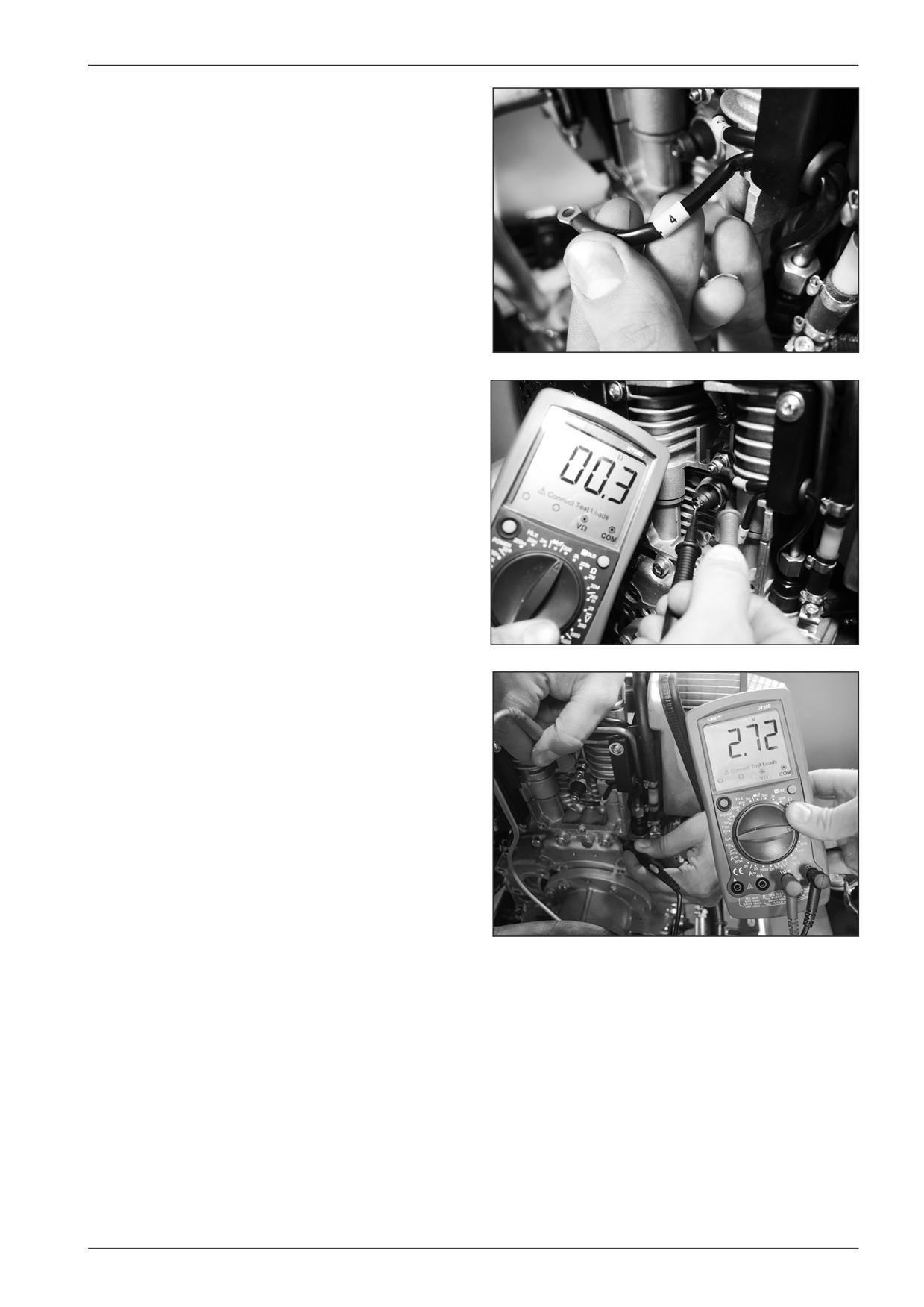
Measuring lubricating oil pressure
switch
Remove wire no. 4.
D451413
Measure the resistance between the frame and the lubricating
oil pressure switch screw.
If the lubricating oil pressure is insufficient, measure the closed
circuit - the resistance is close to zero. After starting the engine
measure the opened circuit.
D451414
Before measuring voltage make sure that the key in ignition is
in the “I” position.
The voltage between wire no. 4 and the engine frame with the
engine started is approximately 2.7 V.
D451412
F80W
49
7
Engine
7.3.5
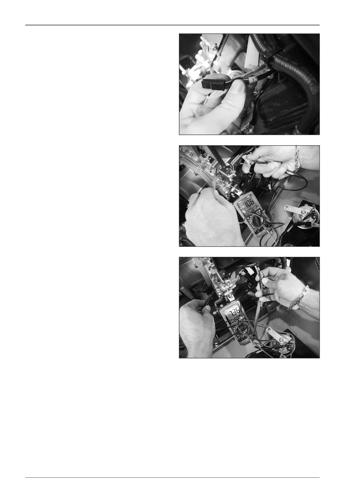
Measuring extinguishing valve
Before measuring voltage make sure that the key in ignition is
in the “I” position.
Remove wire no. 7.
D451415
Measure the resistance between the wire at the output from the
coil and the machine frame.
The measured resistance is approximately 10.5 Ω.
D451416
Measure the voltage of the extinguishing coil between wire no.
7 and the engine frame.
The voltage of the extinguishing valve is approximately 7.3 V.
D451417
50
F80W
WORKSHOP MANUAL
7.3.6
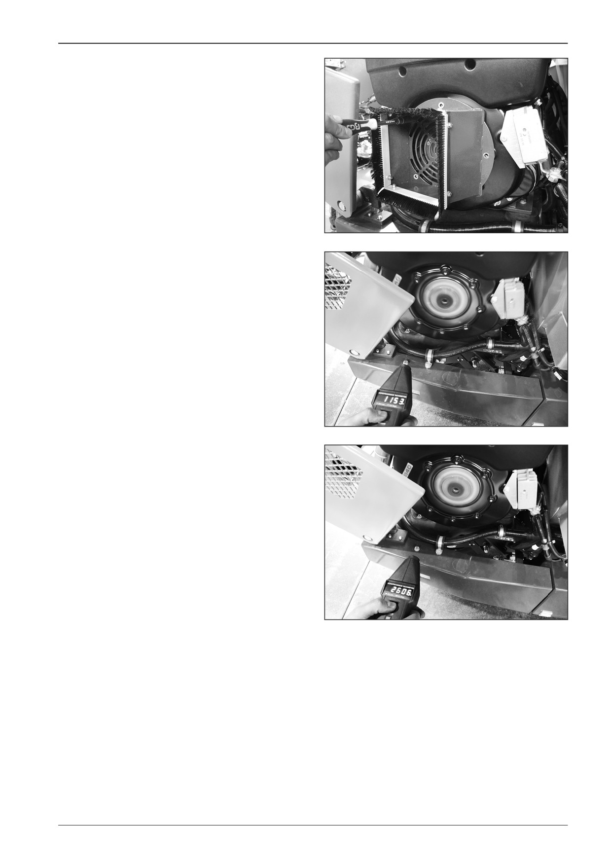
Measuring engine speed
Remove the cover.
D451418
Measure the engine speed using a revolution counter.
Measure idling of approximately 1200 RPM.
D451419
Measure maximum speed of approximately 2600 RPM.
D451420
F80W
51
7
Engine
7.4
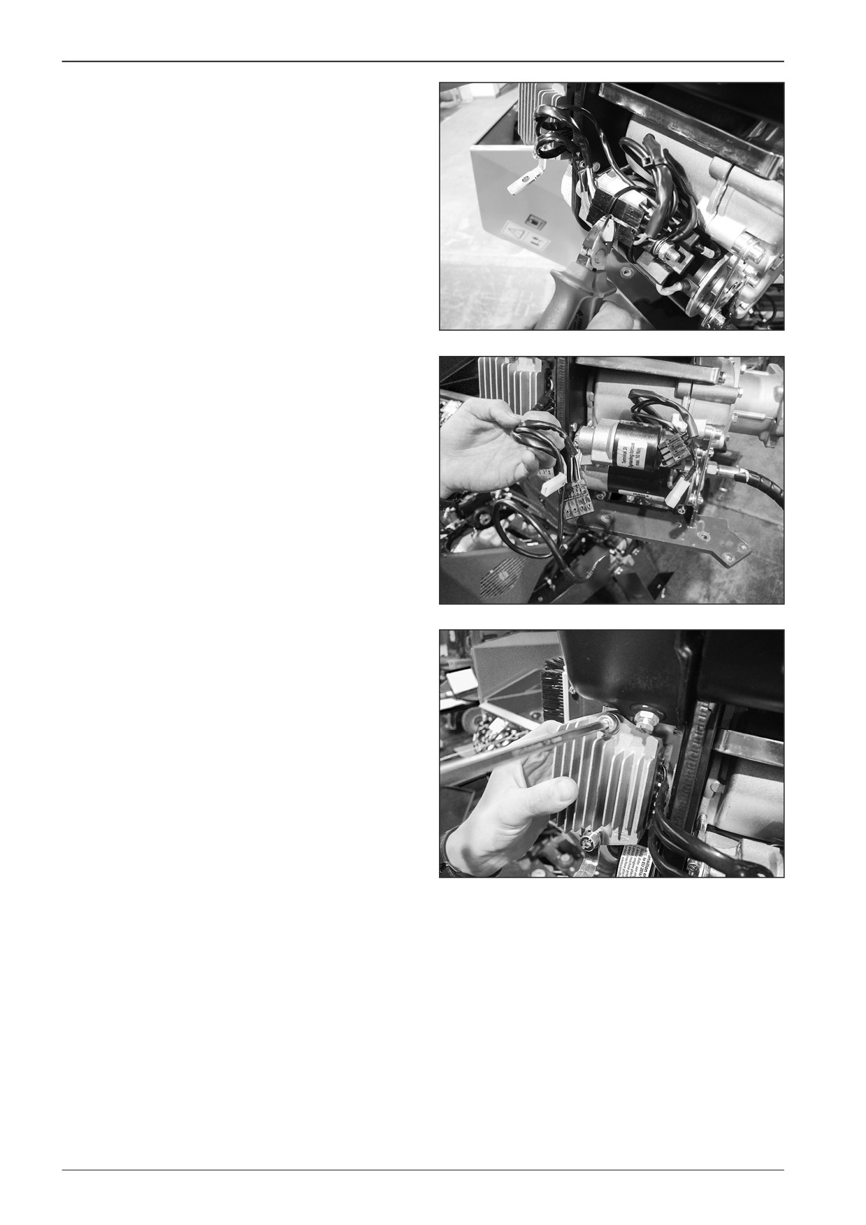
Dismounting the charging controller
Dismount the charging controller from the machine with the
switched off battery disconnecter and with the closed gas bot-
tle valve.
Cut off the binding straps.
D451421
Disconnect the wire and connectors of the charging controller.
D451422
Remove the screws.
D451423
52
F80W
WORKSHOP MANUAL
7.5
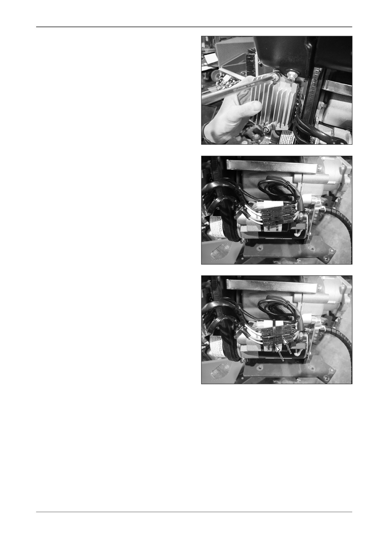
Mounting the charging controller
Mount the charging controller to the machine with the switched
off battery disconnecter and with the closed gas bottle valve.
Fasten the controller.
D451423
Connect the wire and connectors of the charging controller.
D451425
Connect the wire and connectors and fasten them with a bind-
ing strap.
D451424
F80W
53
7
Engine
7.6
Dismounting the engine
Dismount the engine from the machine with the switched off
battery disconnecter and with the closed gas bottle valve.
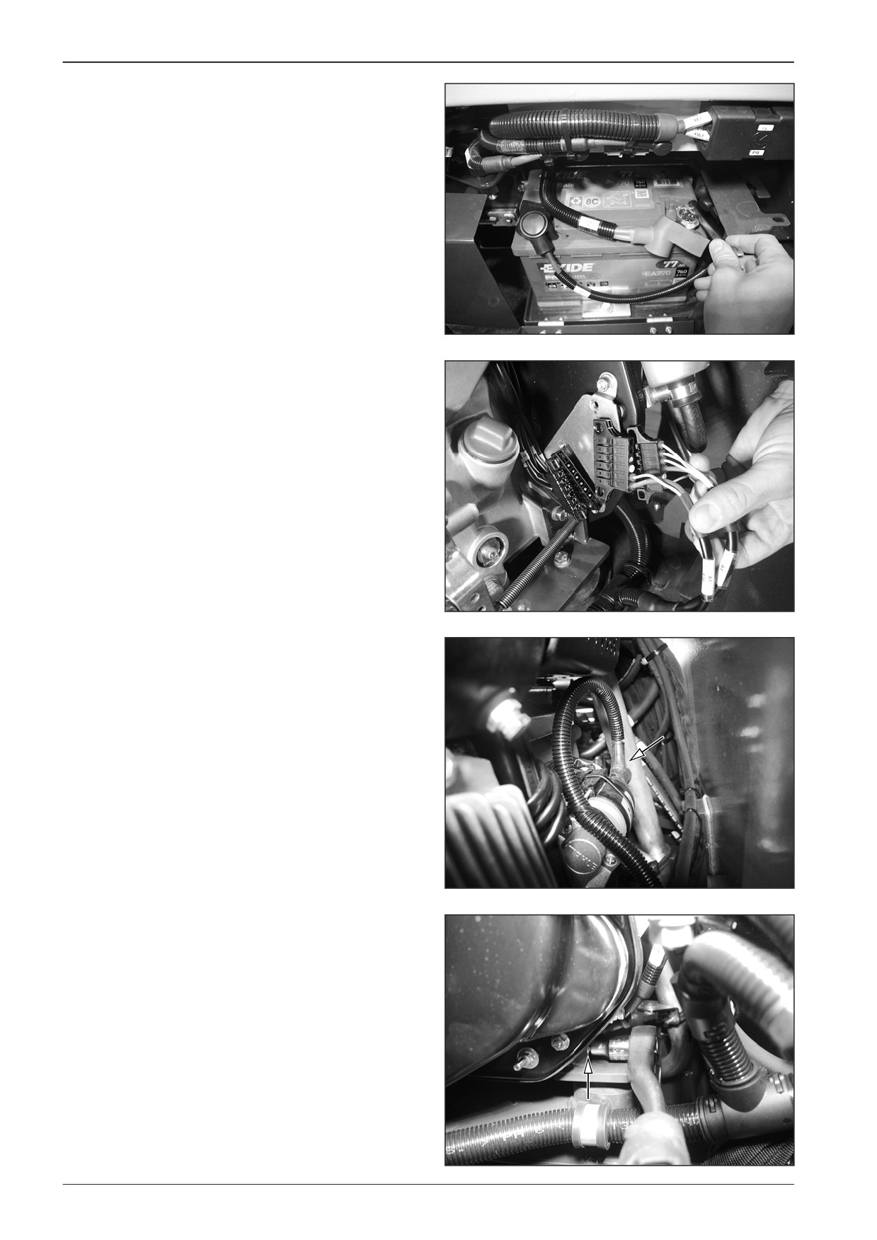
Disconnect the battery.
D451426
Disconnect the connectors.
D451427
Dismount the wire to the starter.
D451428
Dismount the engine earthing wire.
D451429
54
F80W
WORKSHOP MANUAL
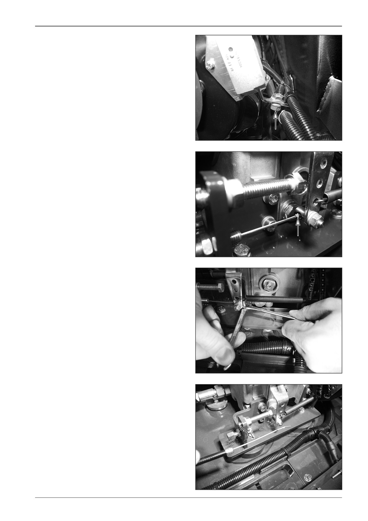
Remove the holder.
D451430
Mark the cable (e.g. by an alcohol marker) to facilitate back as-
sembly.
D451473
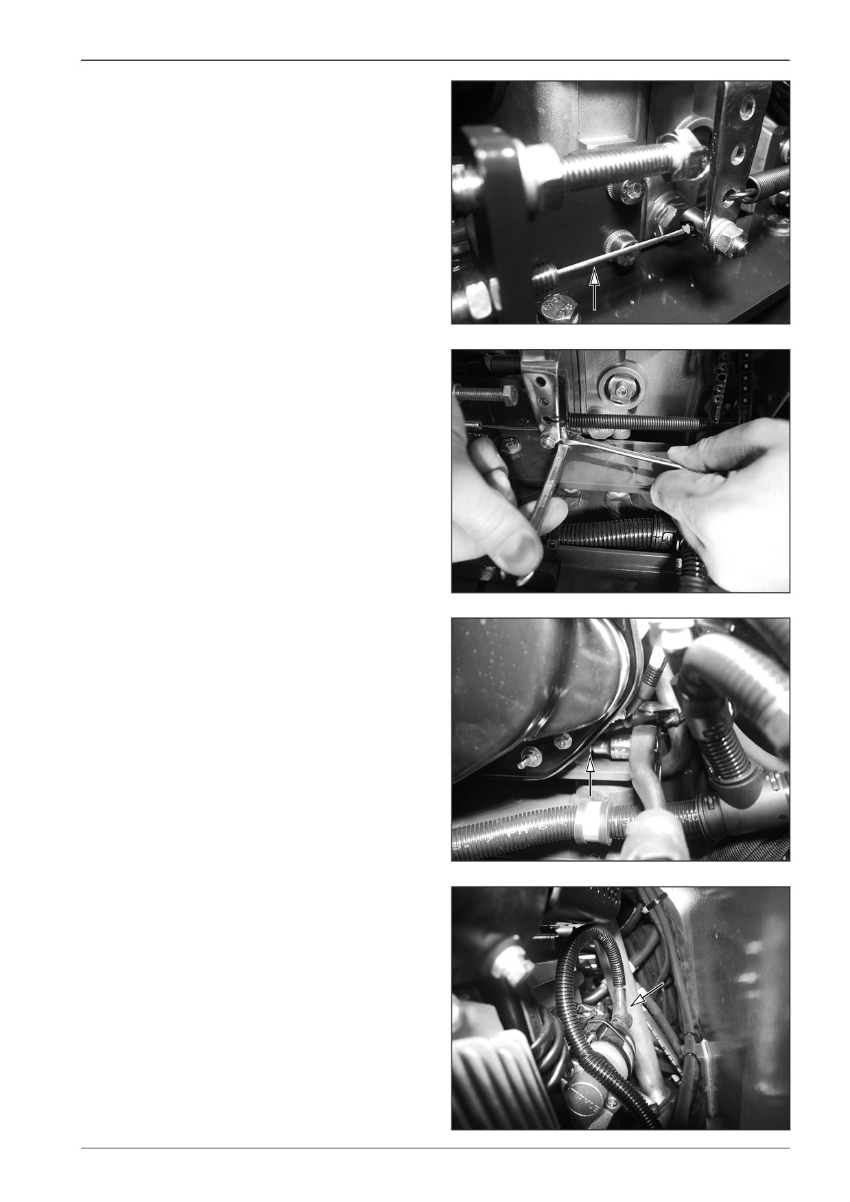
Loosen the locking screw of the engine speed cable.
D451431
Pull out the cable.
D451432
F80W
55
7
Engine
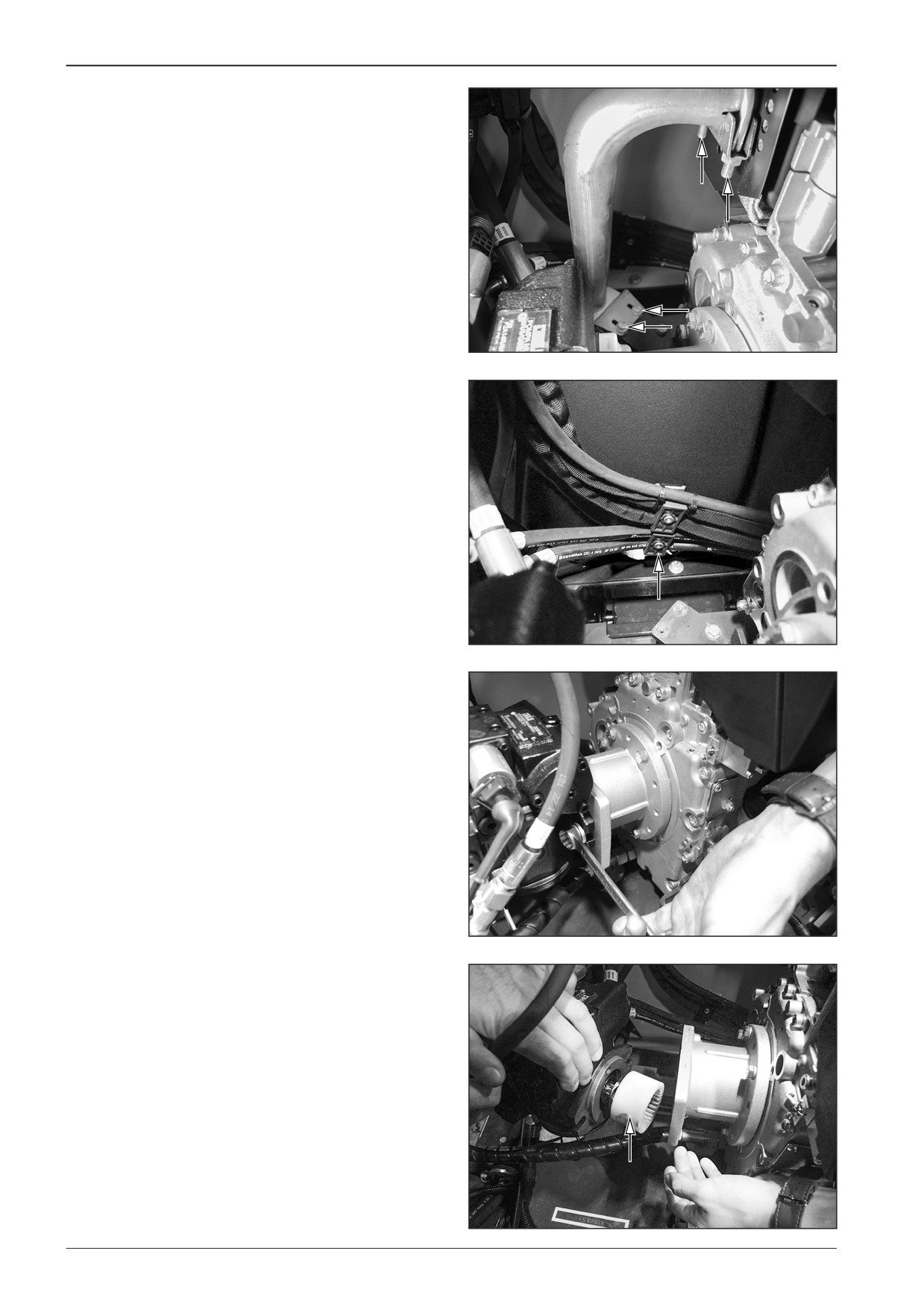
Remove the exhaust clip and holder.
D451433
Remove the lower hose clip.
D451434
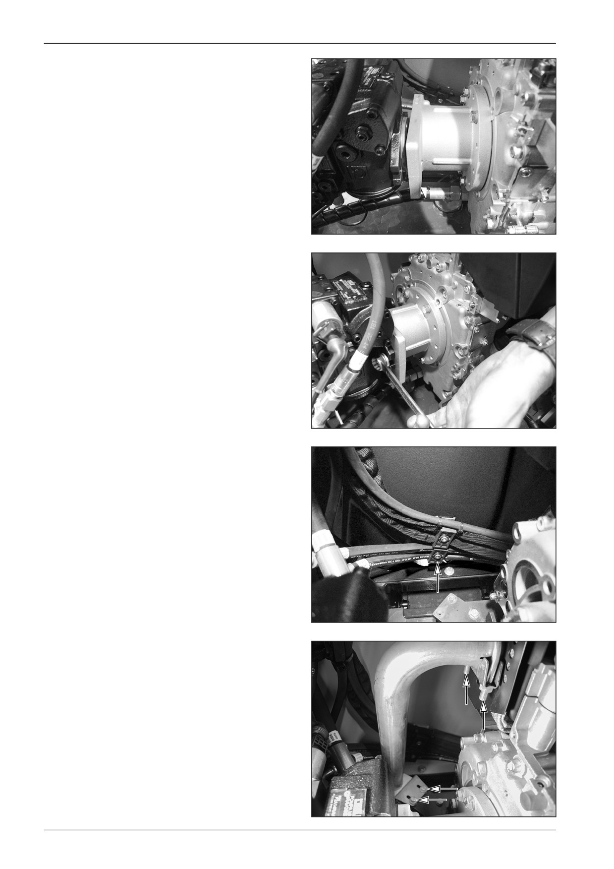
Remove pump bolts.
D451435
Move the pump aside and remove the coupling.
D451436
56
F80W
WORKSHOP MANUAL
D451437
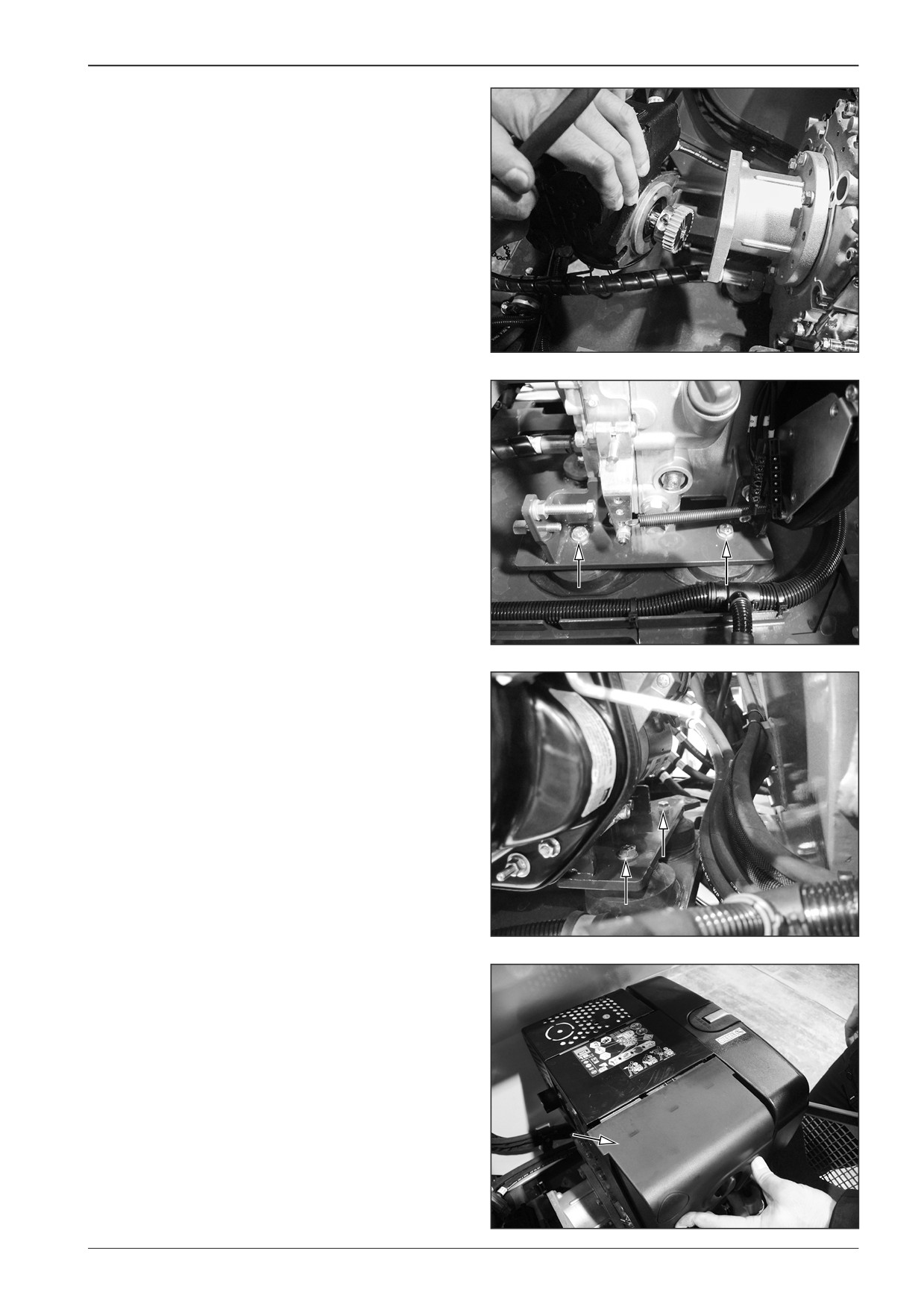
Remove the screws of the engine holder (4x).
D451438
D451439
Remove the air filter cover.
D451440
F80W
57
7
Engine
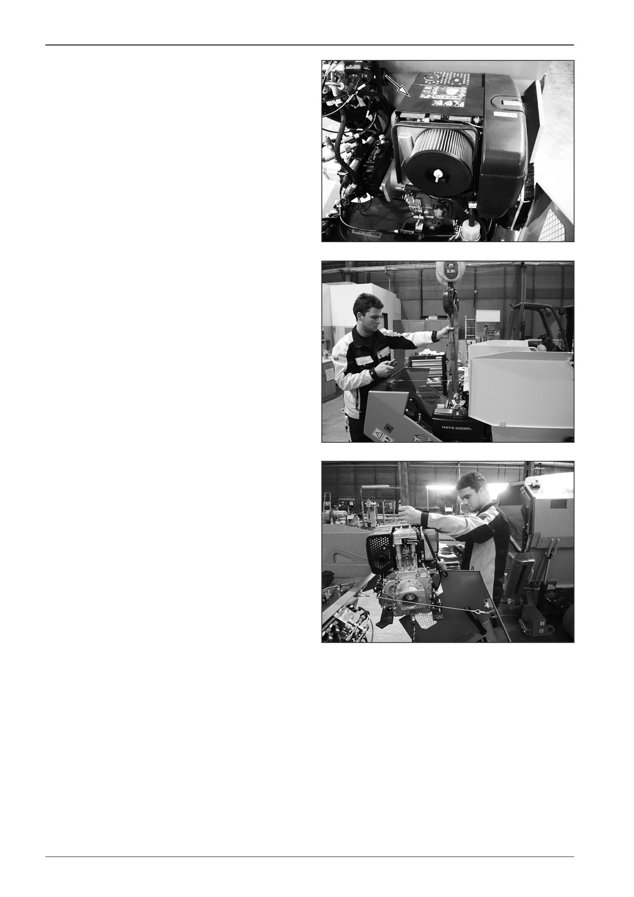
Remove the top engine cover.
D451651
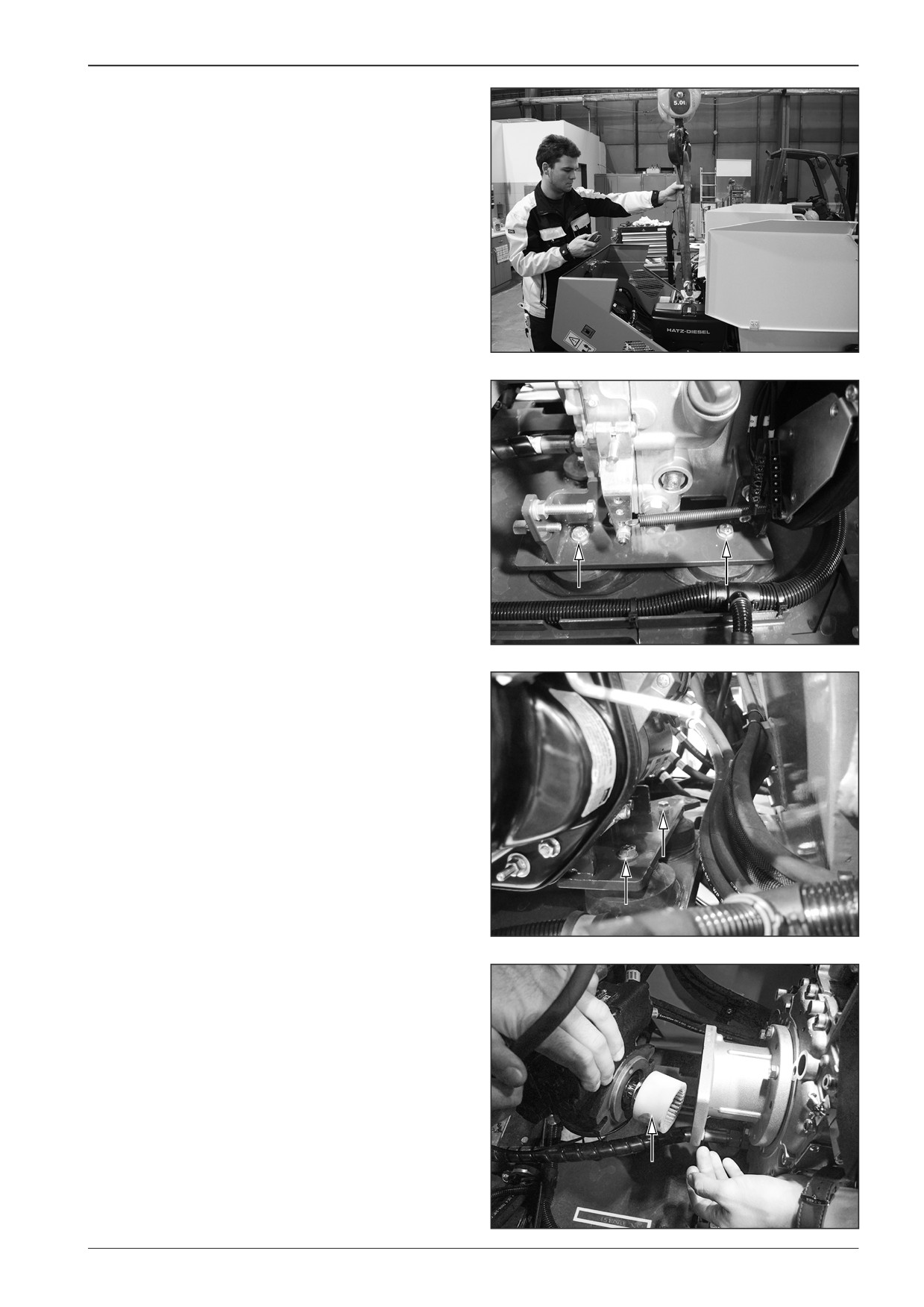
Hang the engine in the lifting lug on the crane.
D451442
D451443
58
F80W
WORKSHOP MANUAL
7.7
Mounting the engine
Mount the engine to the machine with the switched off battery
disconnecter and with the closed gas bottle valve.
Start and place the engine on the rubber-metals of the engine.
D451442
Mount the screws of the engine holder and tighten them.
D451438
D451439
Fit the coupling onto the pump and insert the pump to the en-
gine.
D451436
F80W
59
7
Engine
D451444
Mount the screws of the pump.
Remove the lifting lug.
D451435
Mount the lower hose clip.
D451434
Mount the exhaust clip and holder.
D451433
60
F80W
WORKSHOP MANUAL
Mount the engine speed cable.
D451474
Mount the locking screw of the engine speed cable.
Note
Make sure that the mark of the cable is at the same place.
D451431
Mount the engine earthing wire.
D451429
Mount the wire to the starter.
D451428
F80W
61
7
Engine
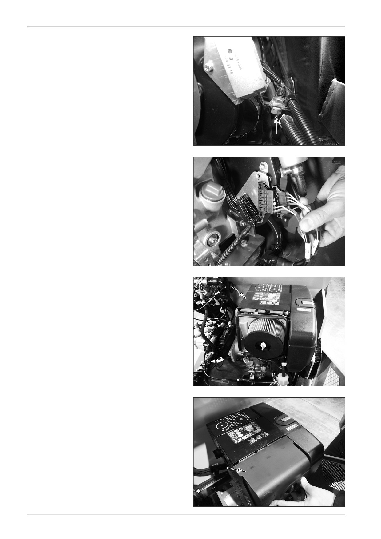
Mount the holder.
D451430
Connect the connectors.
D451427
Mount the top engine cover.
D451651
Mount the air filter cover.
D451440
62
F80W
WORKSHOP MANUAL
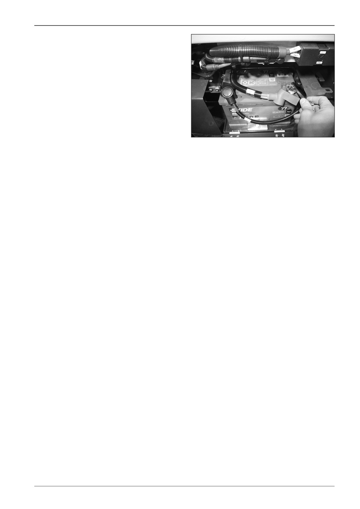
Connect the battery.
D451426
F80W
63

7
Engine
7.8
Engine speed adjustment
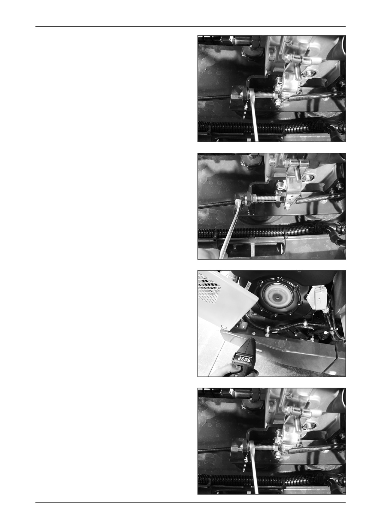
Measure the engine speed using a revolution counter.
Idle engine speed
Start the engine and set the engine speed adjusting controller
to idle speed.
Loosen the lock nut.
D451445
Turn the screw until it reaches 1200 RPM.
D451447
D451419
Tighten the lock nut.
D451445
64
F80W
WORKSHOP MANUAL
Maximum engine speed
Set the engine speed adjusting controller to the maximum speed.
Loosen the lock nut.
D451446
Turn the screw until it reaches 2600 RPM.
D451447
D451420
Tighten the lock nut.
D451446
F80W
65
WORKSHOP MANUAL
8
Steering
F80W
67
8
Steering
8.1
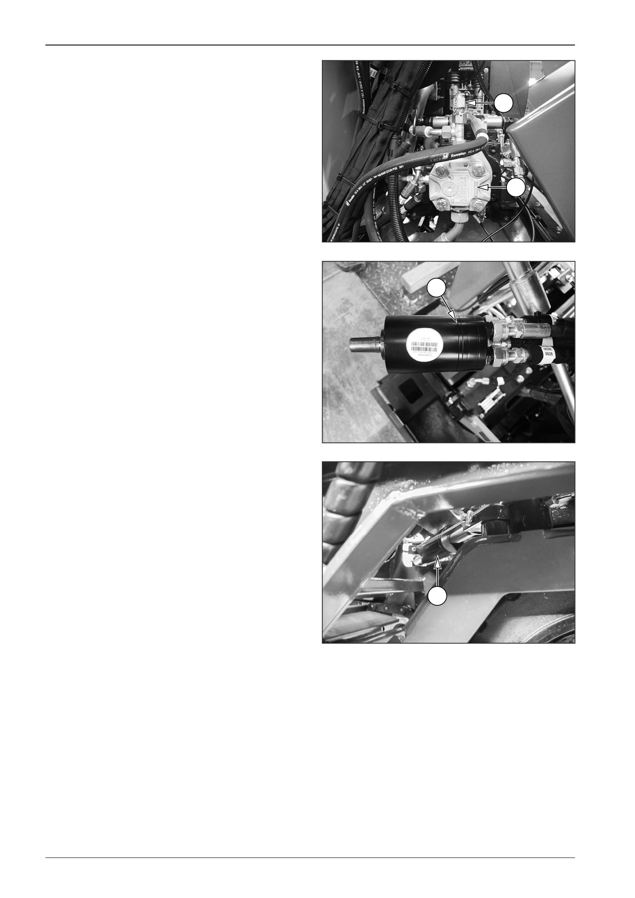
Description of basic elements
1
Service pump
2
Measuring point for pressure measurement
2
1
D451448
3
Power steering
3
DD451045
4
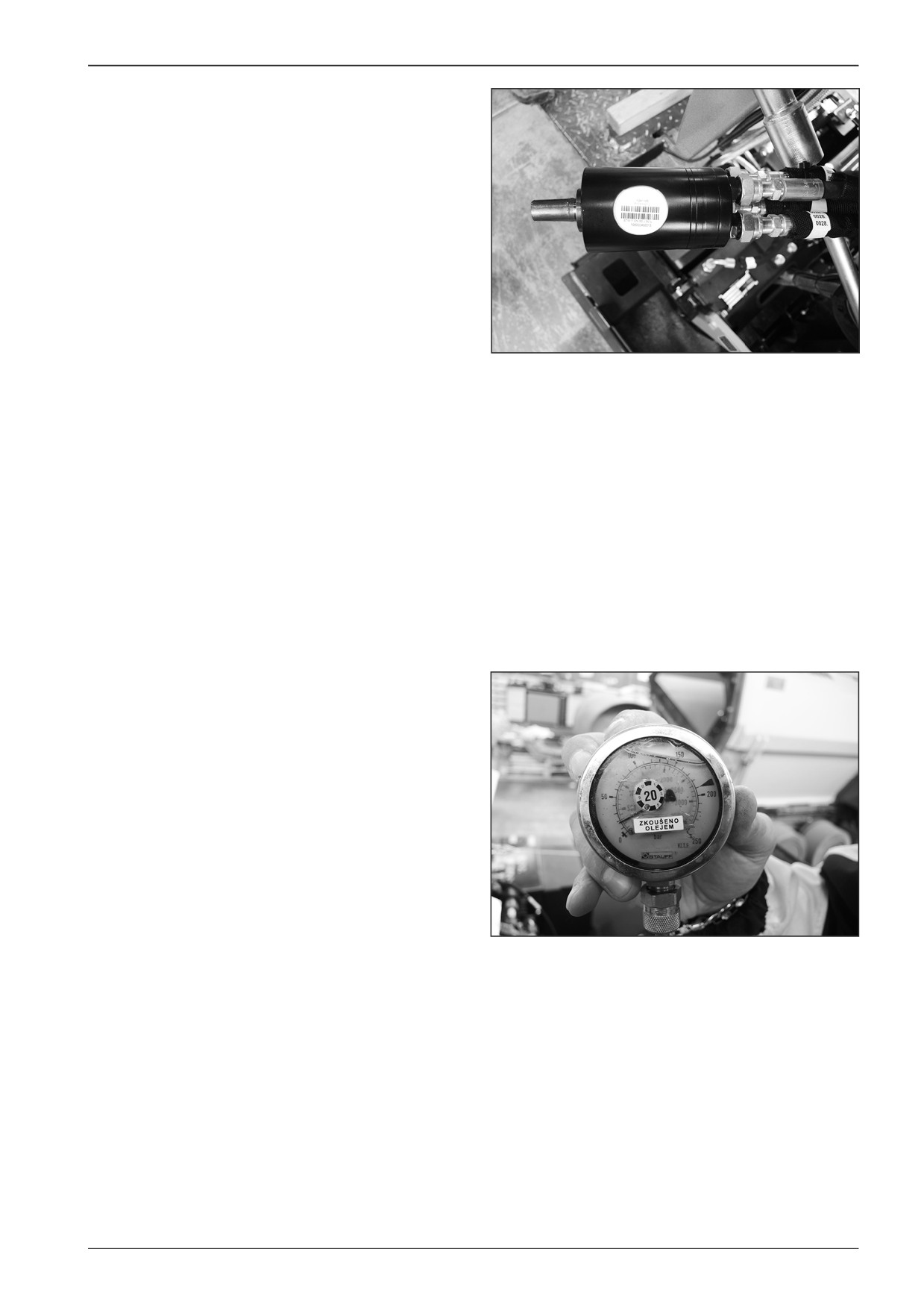
Steering hydraulic motor
4
D451450
68
F80W
WORKSHOP MANUAL
8.2
Technical data of the manufacturer
•
Open-centre power steering
•
Volume of 50 cm3/revolution.
•
Maximum pressure of 50 Bar.
D451063
8.3
Diagnostics
Measuring the steering pressure
•
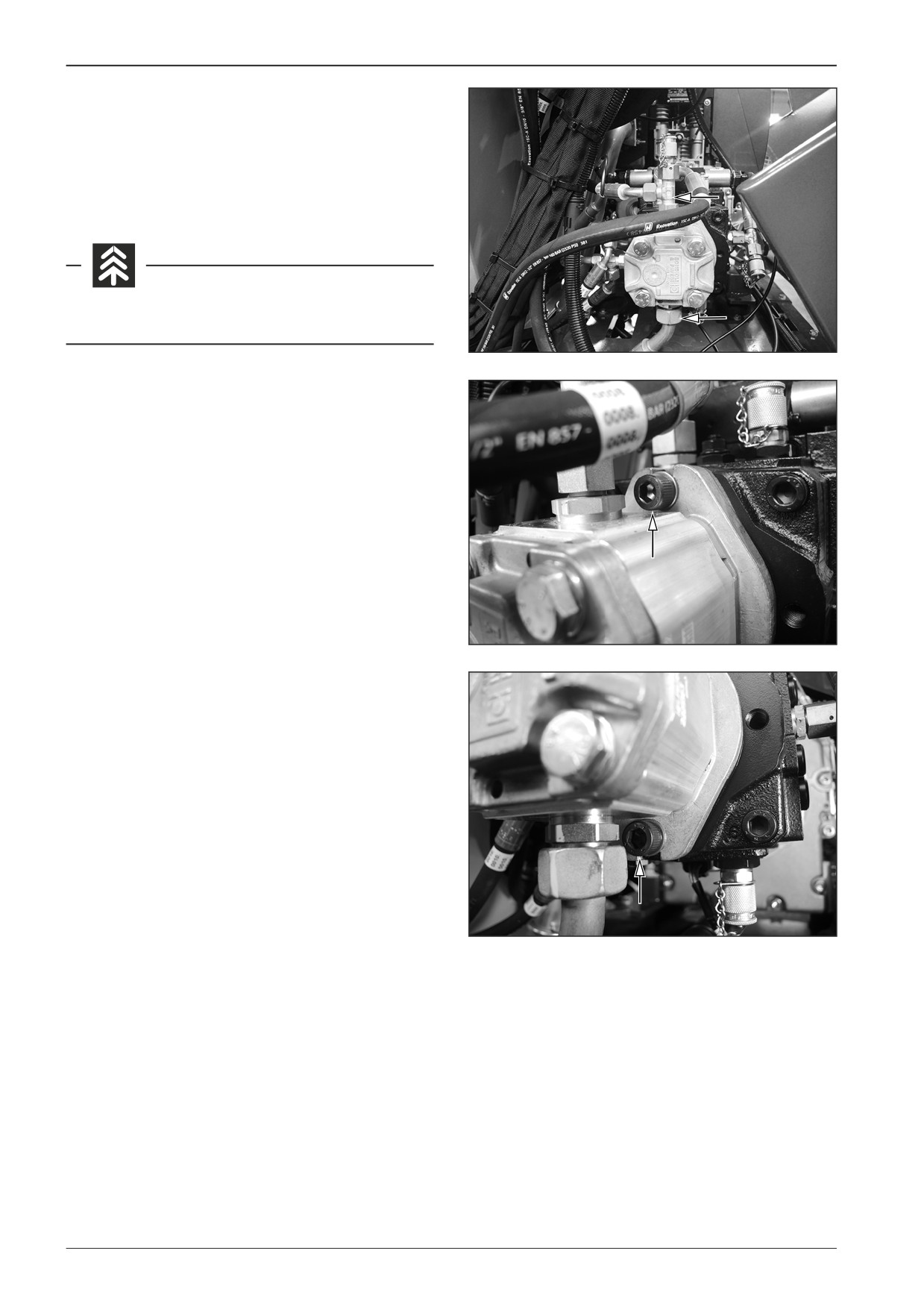
Measure the pressure using a pressure gauge with a suitable
range.
•
Perform the measurement with the heated-up hydraulic oil.
•
Start the engine and set the engine speed adjusting control-
ler to the maximum speed.
Measure the refilling pressure in the steering of approximately
22 Bar.
The maximum pressure in steering limit positions is approxi-
mately 50 Bar.
D451451
Note
In case a different value is measured, contact your dealer or DY-
NAPAC Technical Support.
F80W
69
8
Steering
8.4
Replacement of the gear pump
Perform the replacement of the gear pump with the machine
with the switched off battery disconnecter and with the closed
gas bottle valve.
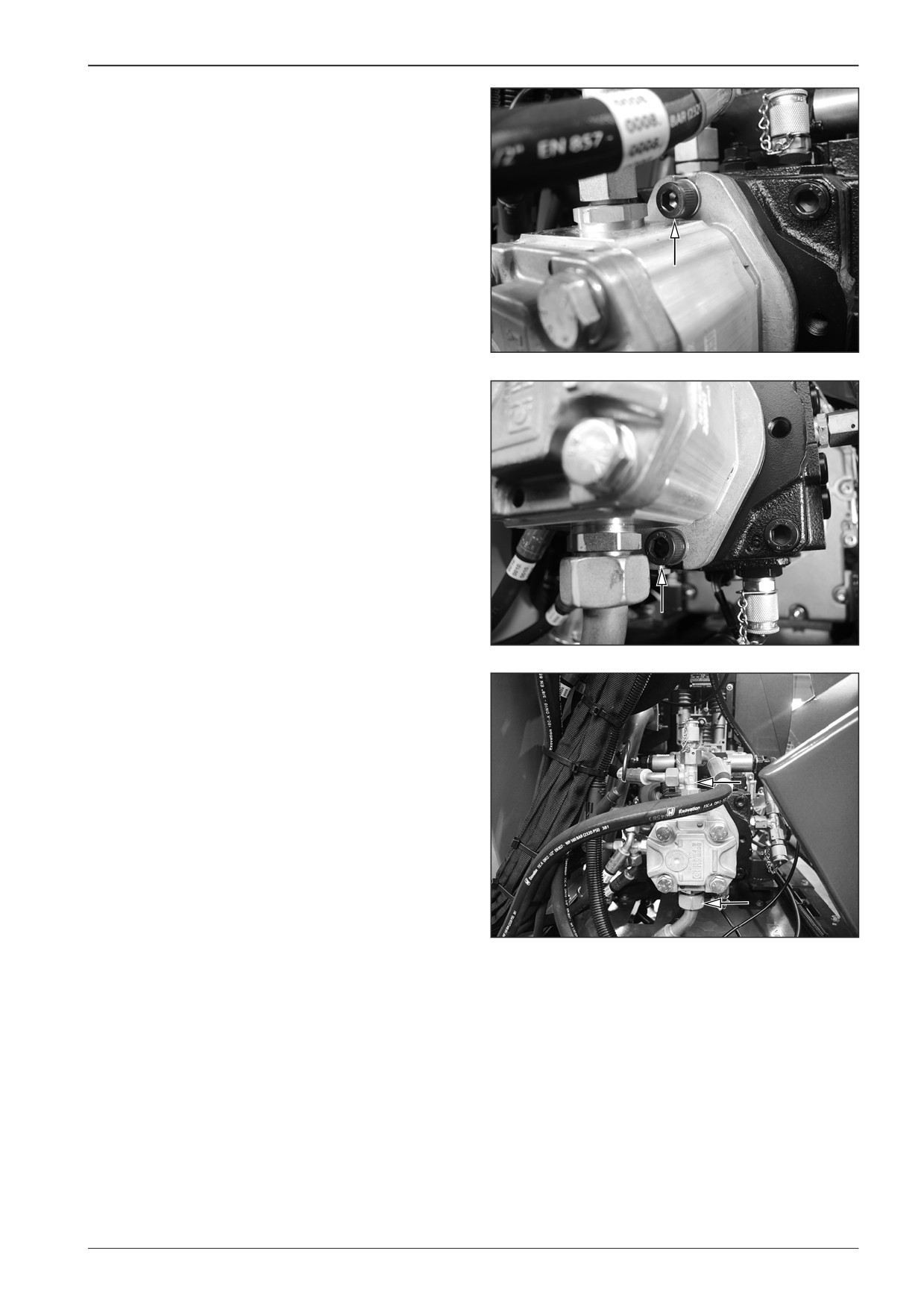
Remove the suction and discharge pump hose.
Avoid the oil soaking into the ground.
D451452
Remove the screws.
Replace the pump with a new one.
D451453
D451454
70
F80W
WORKSHOP MANUAL
Mount the screws and fasten the pump.
D451453
D451454
Mount the suction and discharge hose.
D451452
F80W
71
8
Steering
8.5
Dismounting the steering linear
hydraulic motor
Dismount the steering linear hydraulic motor from the machine
with the switched off battery disconnecter and with the closed
gas bottle valve.
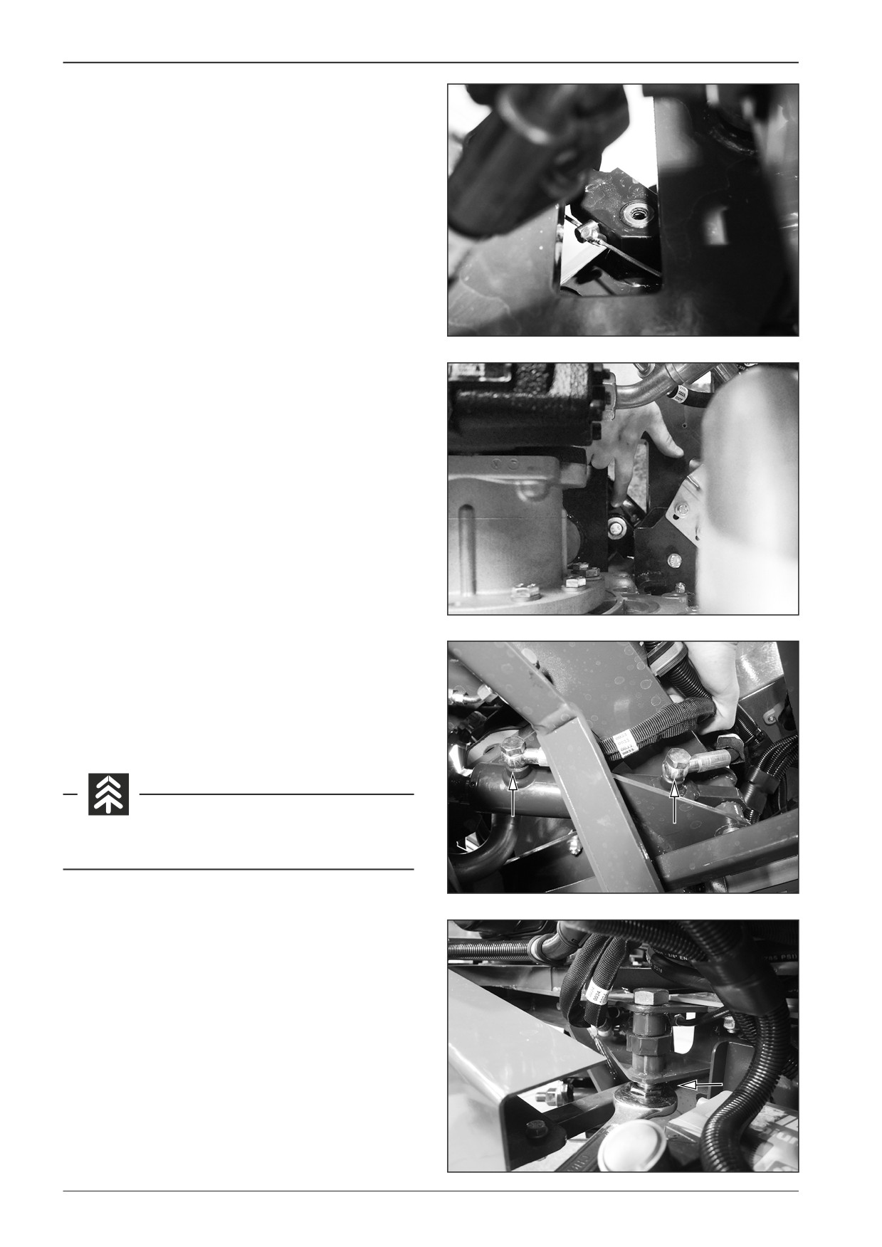
Turn the steering wheel to the maximum right position.
Remove the cable on the steering hydraulic motor.
Note
Mark the cable (e.g. by an alcohol marker) to facilitate back as-
sembly.
D451458
Remove the screw of the steering hydraulic motor.
D451455
Remove the screws of hoses of the steering hydraulic motor.
Note
Place a container underneath the hoses of the steering hydraulic
motor to trap the oil.
Avoid the oil soaking into the ground.
D451456
Remove the screw of the steering hydraulic motor.
D451457
72
F80W
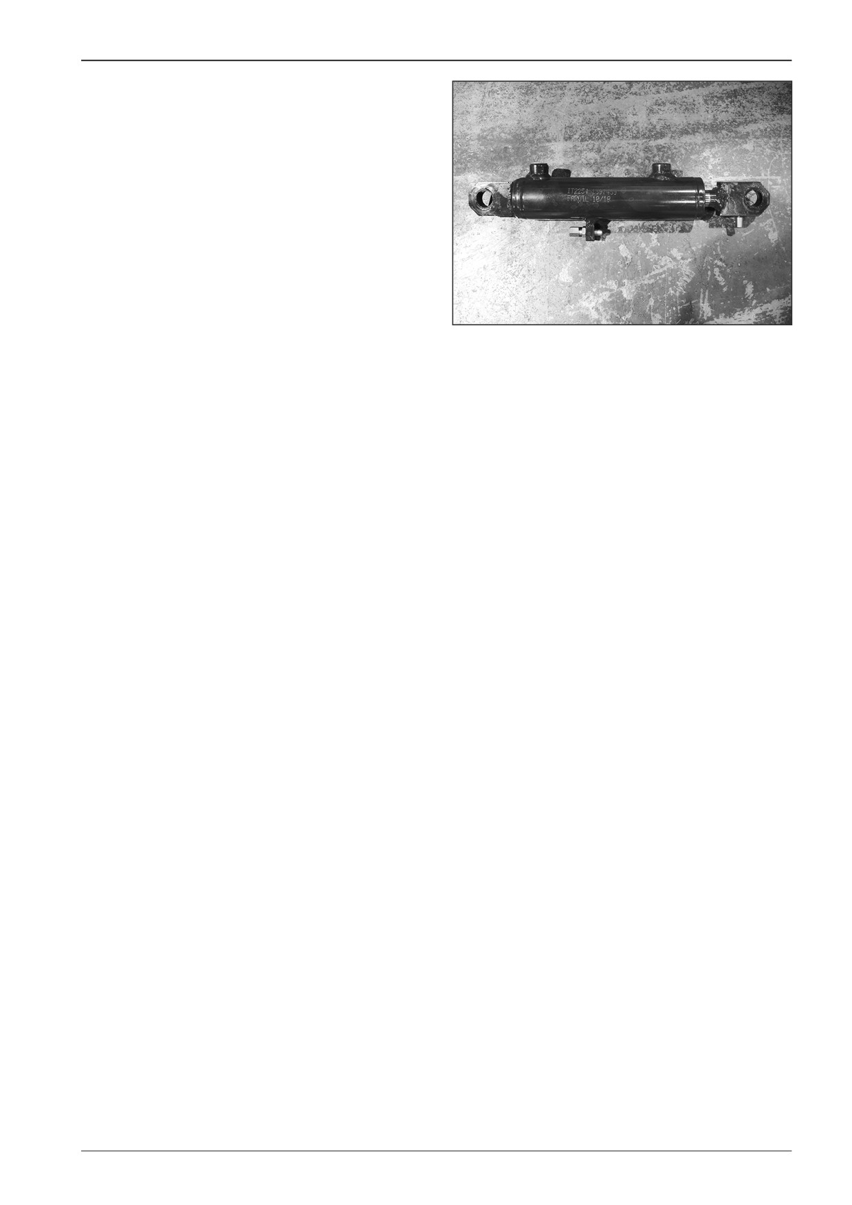
WORKSHOP MANUAL
Replace the steering hydraulic motor.
D451459
F80W
73
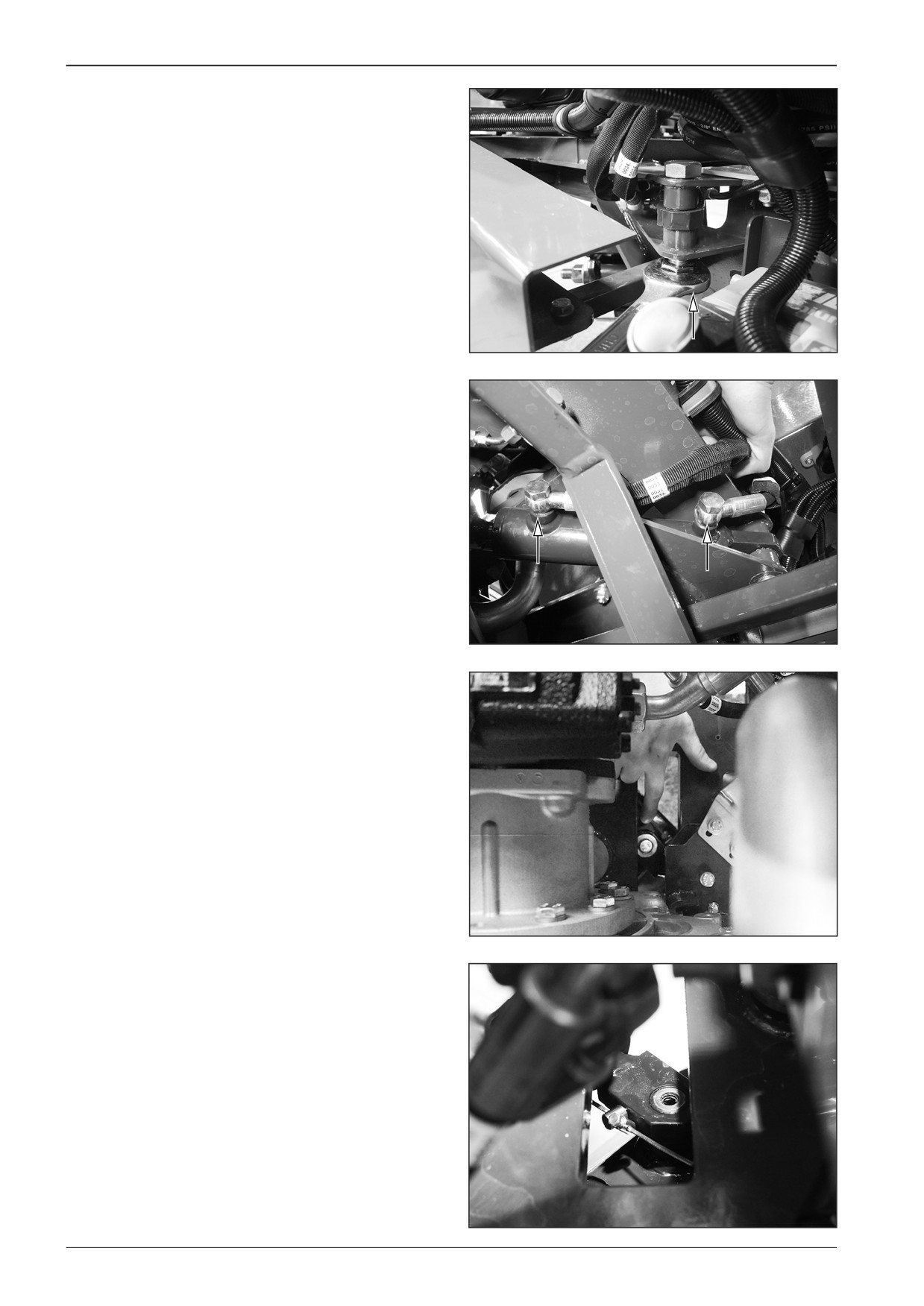
8
Steering
8.6
Mounting the steering linear hydraulic
motor
Mount the steering linear hydraulic motor to the machine with
the switched off battery disconnecter and with the closed gas
bottle valve.
Insert the steering hydraulic motor and mount the screw.
D451460
Mount the screws of hoses of the steering hydraulic motor.
D451456
Mount the screw of the steering hydraulic motor and glue it with the
LOXEAL 83∙54 adhesive.
D451455
Mount the cable on the steering hydraulic motor.
Note
Make sure that the mark of the cable is at the same place.
During the back assembly it is necessary to adjust the steering
indicator to the central position by loosening or tightening the
cable on the steering hydraulic motor.
D451458
74
F80W
WORKSHOP MANUAL
8.7
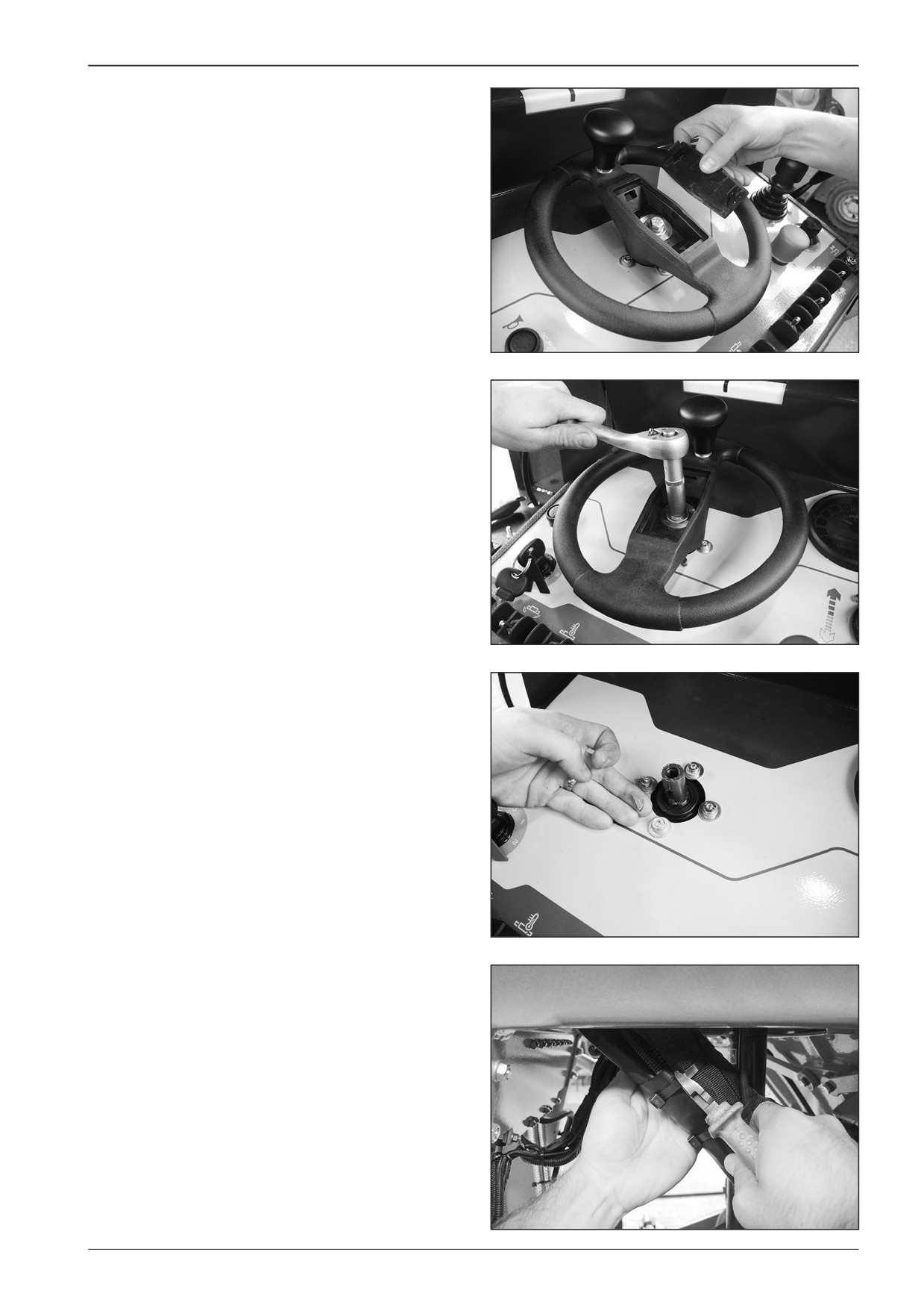
Dismounting the steering unit
Dismount the steering unit from the machine with the switched
off battery disconnecter and with the closed gas bottle valve.
Remove the cover.
D451461
Remove the screw.
D451462
Take out the steering wheel and remove the screws.
D451463
Cut off the binding straps of hydraulic hoses.
D451464
F80W
75
8
Steering
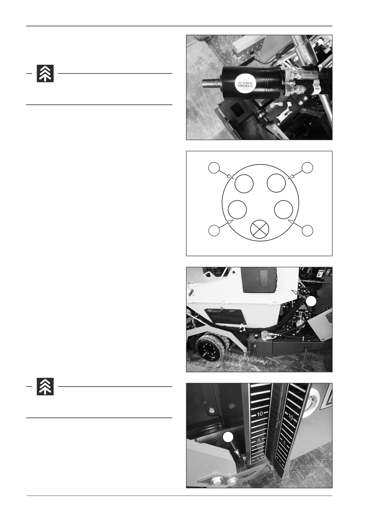
Take out the steering hydraulic unit.
Remove the hydraulic hoses on the steering unit.
Avoid the oil soaking into the ground.
Note
When mounting the steering hydraulic unit back proceed in the
D451465
reverse order and take care of the correct connection of the hy-
draulic hoses.
0018
0034
- Hose 0028 at position T
- Hose 0018 at position P
P
L
– Hose 0034 at position L
- Hose 0033 at position R
T
R
0028
0033
421523
8.8
Removal of the hydraulic tank
Drain the heated oil from the hydraulic tank.
Perform the hydraulic oil draining when the machine is parked
on a flat and solid surface, the engine and the battery discon-
1
necter are off and the gas bottle is closed.
Open the right material hopper side cover (1).
Place a vessel with a volume of at least 21 l (5.5 gal US) under the
hydraulic oil drain plug (3).
Remove the drain plug (3) from the hydraulic tank.
Drain the oil into the prepared container.
Mount the drain plug (3) onto the hydraulic tank and tighten.
D451255C
Avoid the oil soaking into the ground.
3
D451A466
76
F80W
WORKSHOP MANUAL
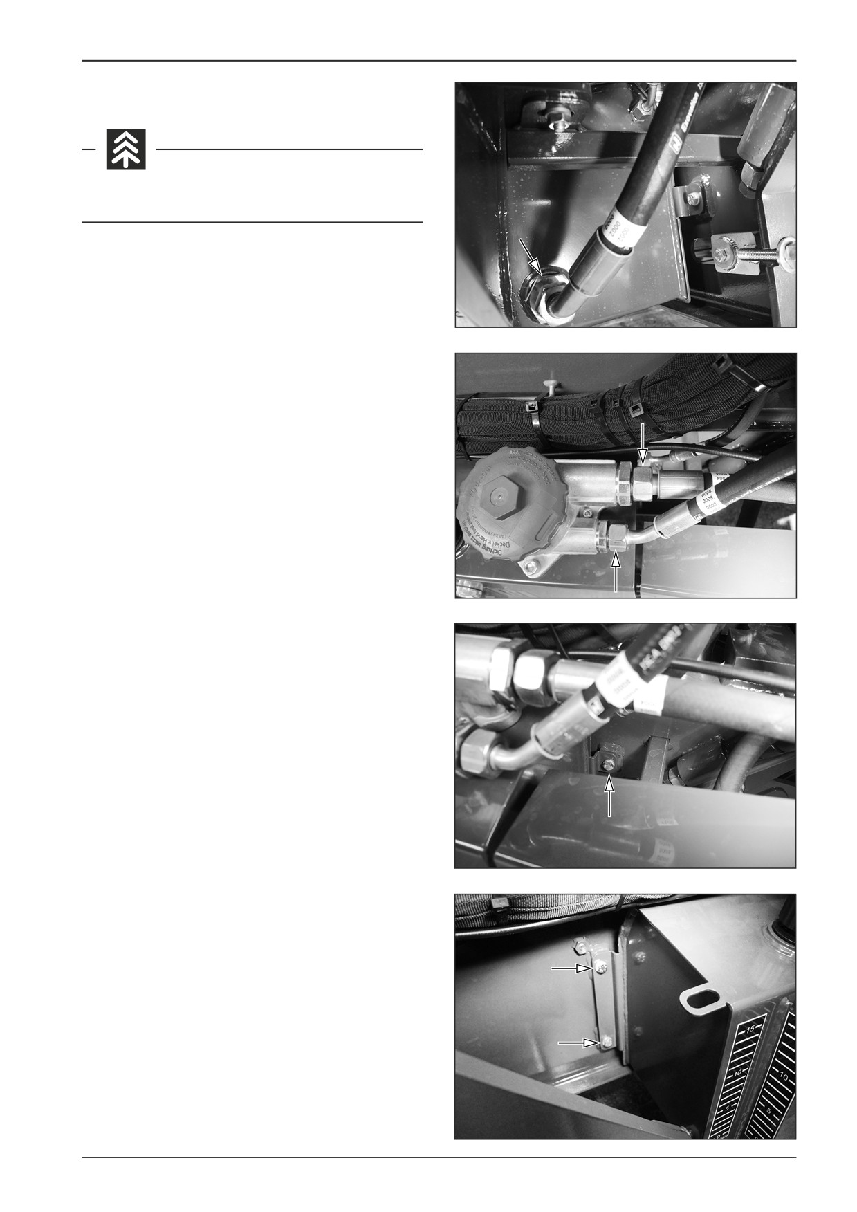
Remove the hydraulic hoses.
Avoid the oil soaking into the ground.
D451467
D451468
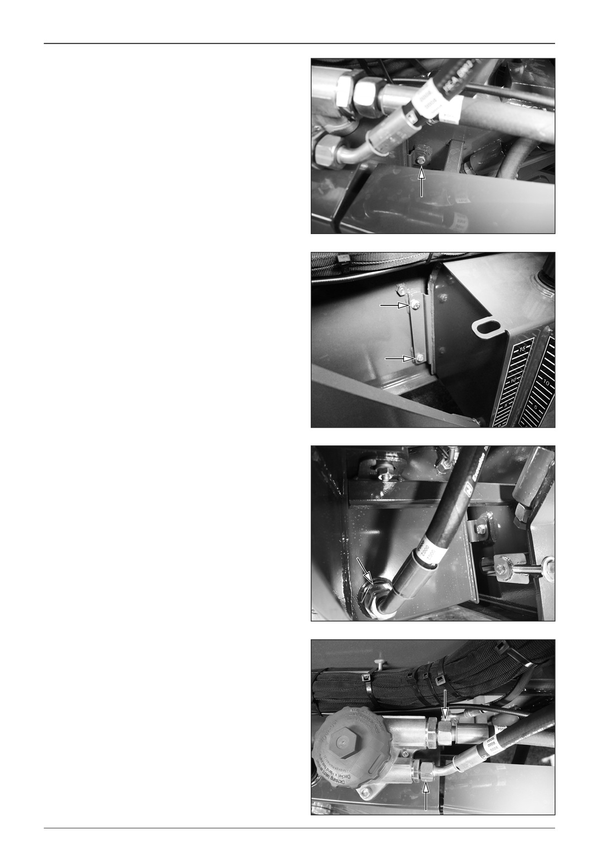
Remove the screws (3x).
D451469
D451470
F80W
77
8
Steering
8.9
Mounting the hydraulic tank
Mount the hydraulic tank to the machine with the switched off
battery disconnecter and with the closed gas bottle valve.
Mount the screws.
D451469
D451470
Mount the hydraulic hoses.
D451467
D451468
78
F80W
WORKSHOP MANUAL
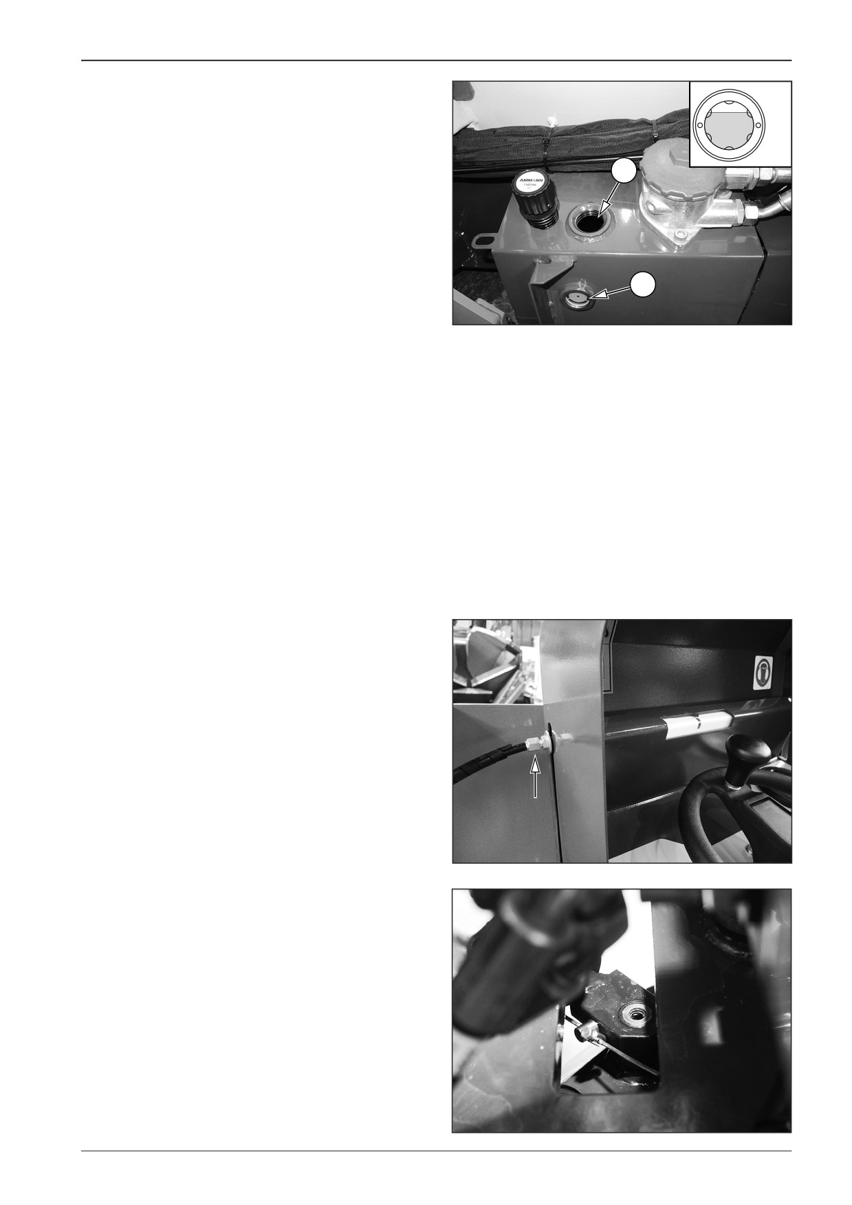
Fill in the hydraulic tank:
MAX
•
Fill in new oil to the hydraulic tank through the hole (1).
•
The prescribed oil volume is 20 l (5.3 gal US).
MIN
•
Check the oil level on the oil gauge (2).
•
The hydraulic oil level must be between the MIN and MAX
1
marks.
2
D451256B
8.10
Adjustment of the front wheel turning
angle indicator
Adjust the indicator by tightening or loosening the adjusting
screw.
D451471
Note
If the tightening or loosening of the adjusting screw is insuf-
ficient, change the position of the cable on the steering linear
hydraulic motor.
D451458
F80W
79
WORKSHOP MANUAL
9
Travel
F80W
81
9
Travel
9.1
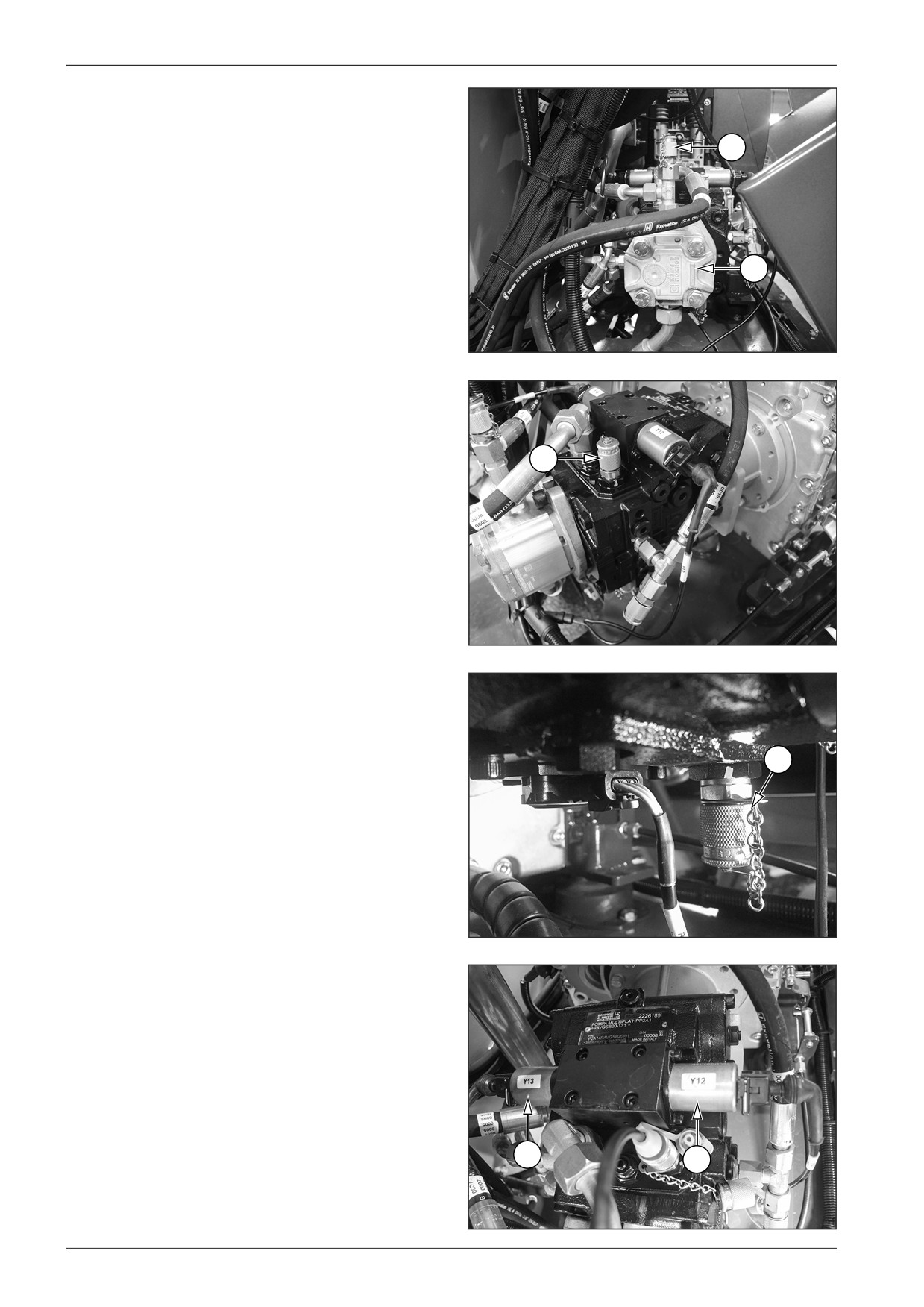
Description of basic elements
1
Service pump
2
2
Measuring point for pressure measurement
1
D451486
3
Measuring point for pressure measurement for forward travel
3
DD451046
4
Measuring point for pressure measurement for reverse travel
4
DD451047
5
Coil of the valve electromagnet for forward travel Y12
6
Coil of the valve electromagnet for forward travel Y13
6
5
DD451048
82
F80W
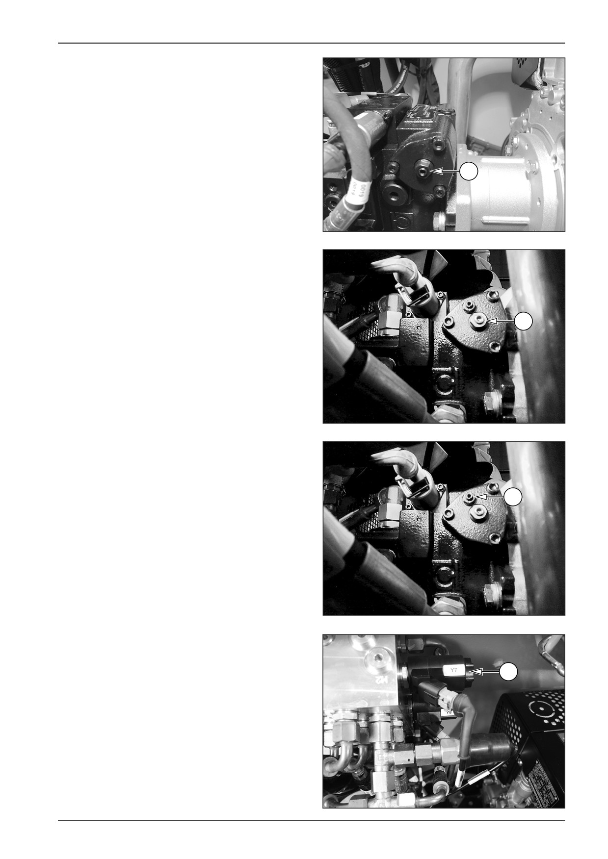
WORKSHOP MANUAL
7
Setting the maximum pump volume
7
DD451049
7
DD451050
8
Setting the neutral pump position
8
DD451051
9
Coil of the brake valve electromagnet Y7
9
DD451052
F80W
83
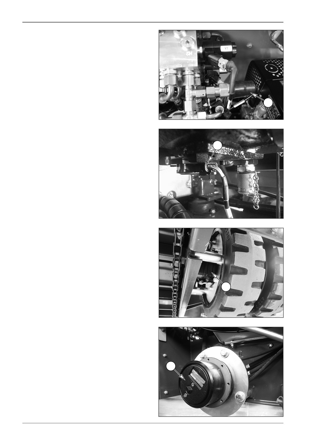
9
Travel
10 Brake pressure switch
10
D451053
11 Pump plate tilt sensor
11
D451054
12 Travel hydraulic motor
12
DD451055
13 Travel gearbox
13
DD451056
84
F80W
WORKSHOP MANUAL
9.2
Diagnostics
9.2.1
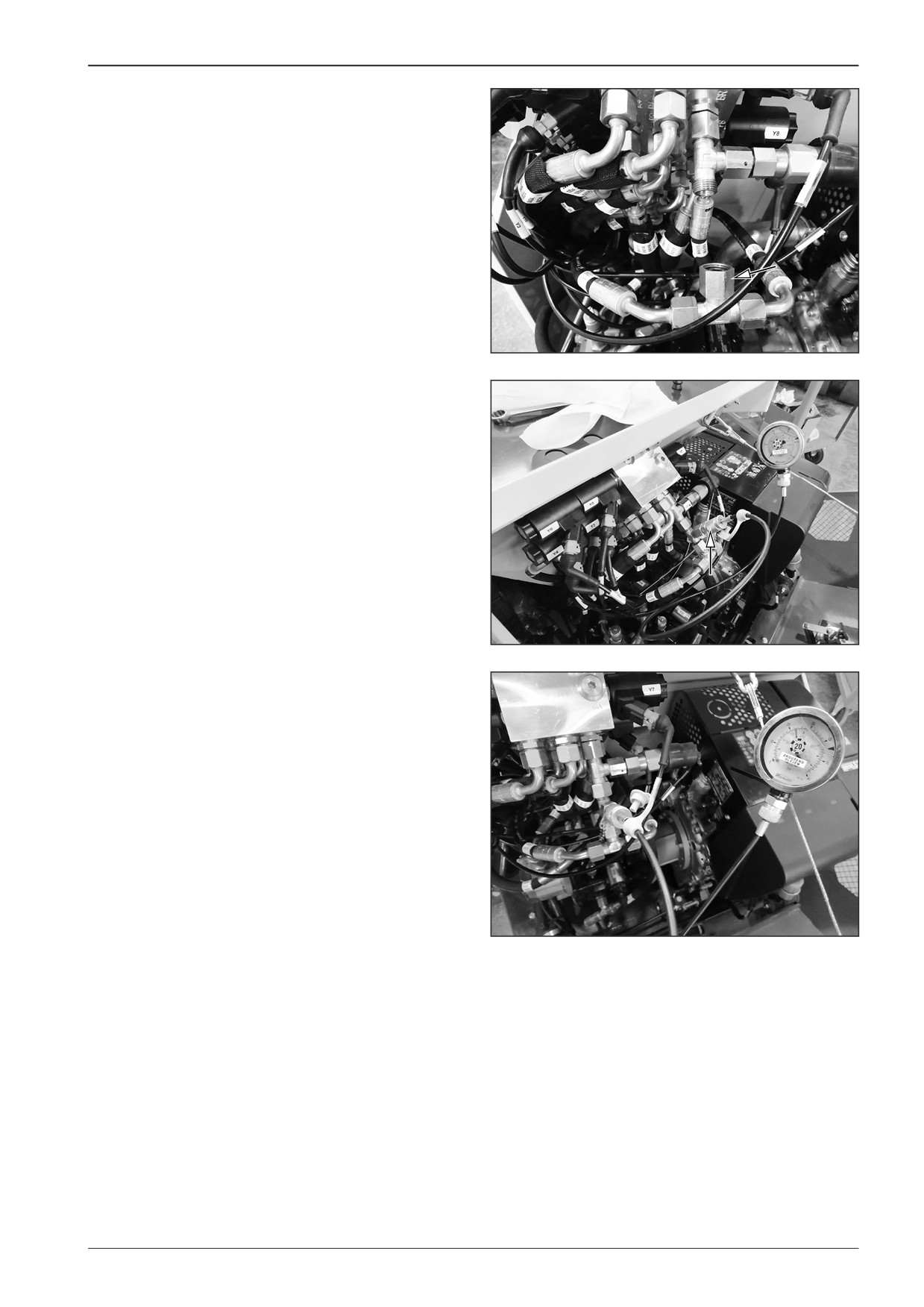
Measuring the brake switch
Brake enabled = the switch disconnected.
•
Brake pressure 0 Bar.
Brake disabled = the switch connected = released brake of the
machine
•
Pressure of 22 Bar.
Measuring brake switch pressure
DD451031
•
Disconnect the hose fittings.
•
Insert the jumper with the measuring point to the circuit
and connect the pressure gauge with a suitable range to it.
•
Start the engine, set the engine speed adjusting controller
to the maximum speed and put the machine in motion.
DD451032
•
Measure the brake release pressure of approximately 22 Bar.
Note
In case a different value is measured, contact your dealer or DY-
NAPAC Technical Support.
DD451033
F80W
85
9
Travel
9.2.2
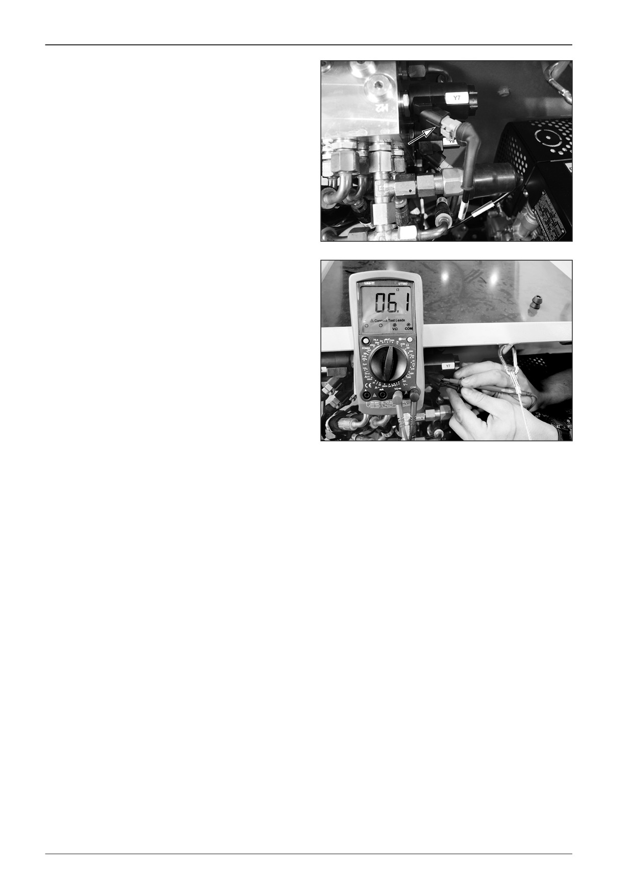
Measuring the brake valve
electromagnet Y7
Disconnect the connector from valve Y7.
D451494
Measure the resistance between outputs of the electromagnet
coil of approximately 6 Ω.
D451498
86
F80W