Dynapac Asphalt paver wheeled F80W Hatz. WORKSHOP MANUAL (2019) - page 6
15
Wiring
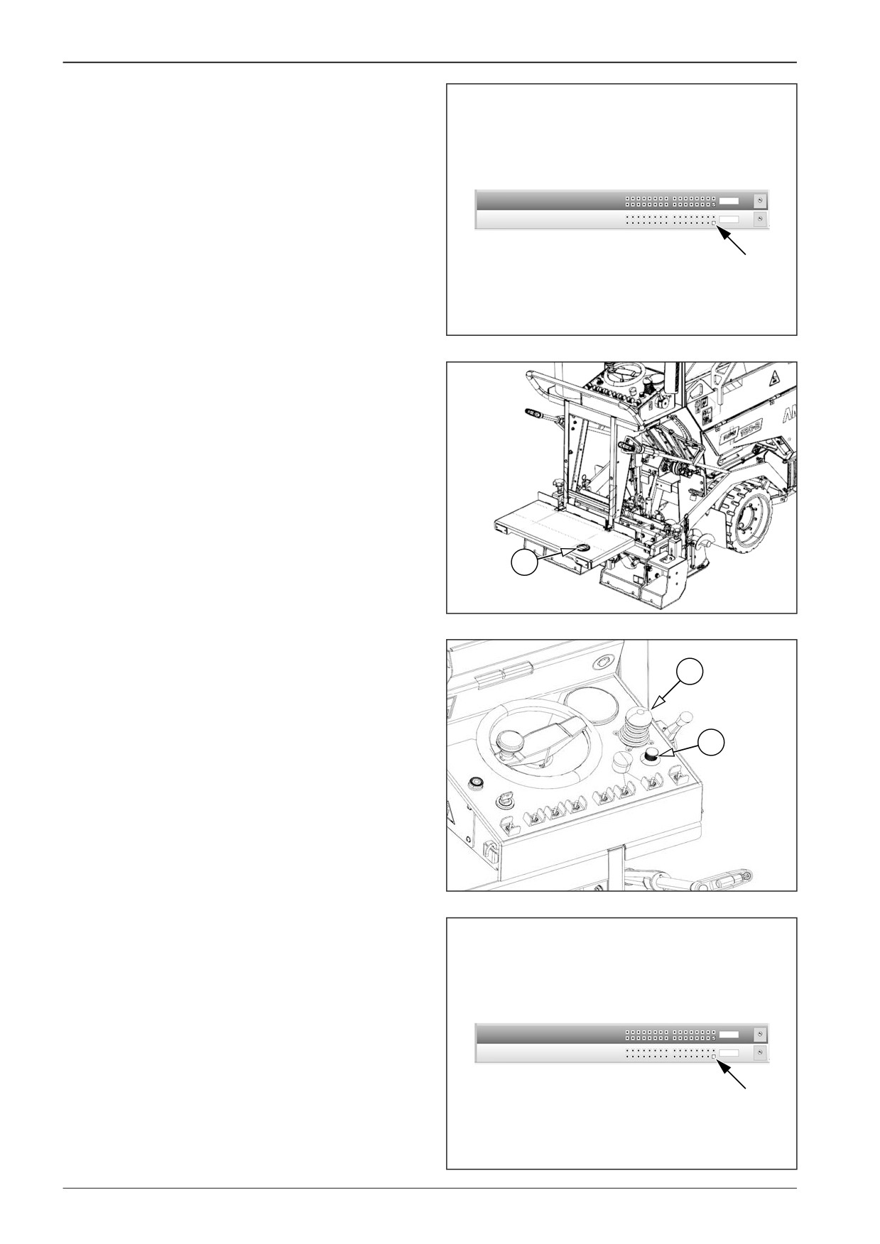
Confirm the setting by checking and subsequent unchecking
the box in “1.7.8 Set value”.
A short sound signal is heard.
1.7.7 Propel pump calib
1
STD
1.7.8 Set value
0
STD
D451C029
Activate the foot switch (48).
48
451686
Shift the travel controller (8) to the reverse travel position.
Slowly turn the paving speed selector (14) so that the machine
8
drives at the lowest possible speed (the wheels are permanently
turning).
14
451C030
Confirm the setting by checking and subsequent unchecking
the box in “1.7.8 Set value”.
A short sound signal is heard.
1.7.7 Propel pump calib
1
STD
1.7.8 Set value
0
STD
D451C029
210
F80W
WORKSHOP MANUAL
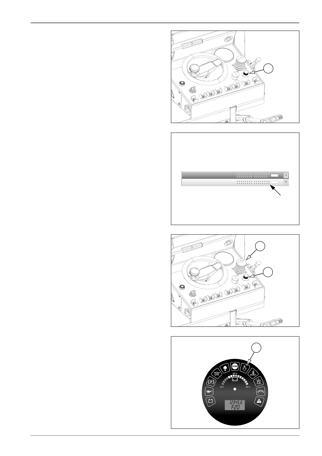
Slowly turn the paving speed selector (14) to the “max” position.
14
451C031
Confirm the setting by checking and subsequent unchecking
the box in “1.7.8 Set value”.
A short sound signal is heard.
1.7.7 Propel pump calib
1
STD
1.7.8 Set value
0
STD
D451C029
Turn the paving speed selector (14) to the “min” position and
wait for the LED indicator (27) to turn off.
8
Then shift the travel controller (8) to the neutral position.
14
451C030
27
D451C033
F80W
211
15
Wiring
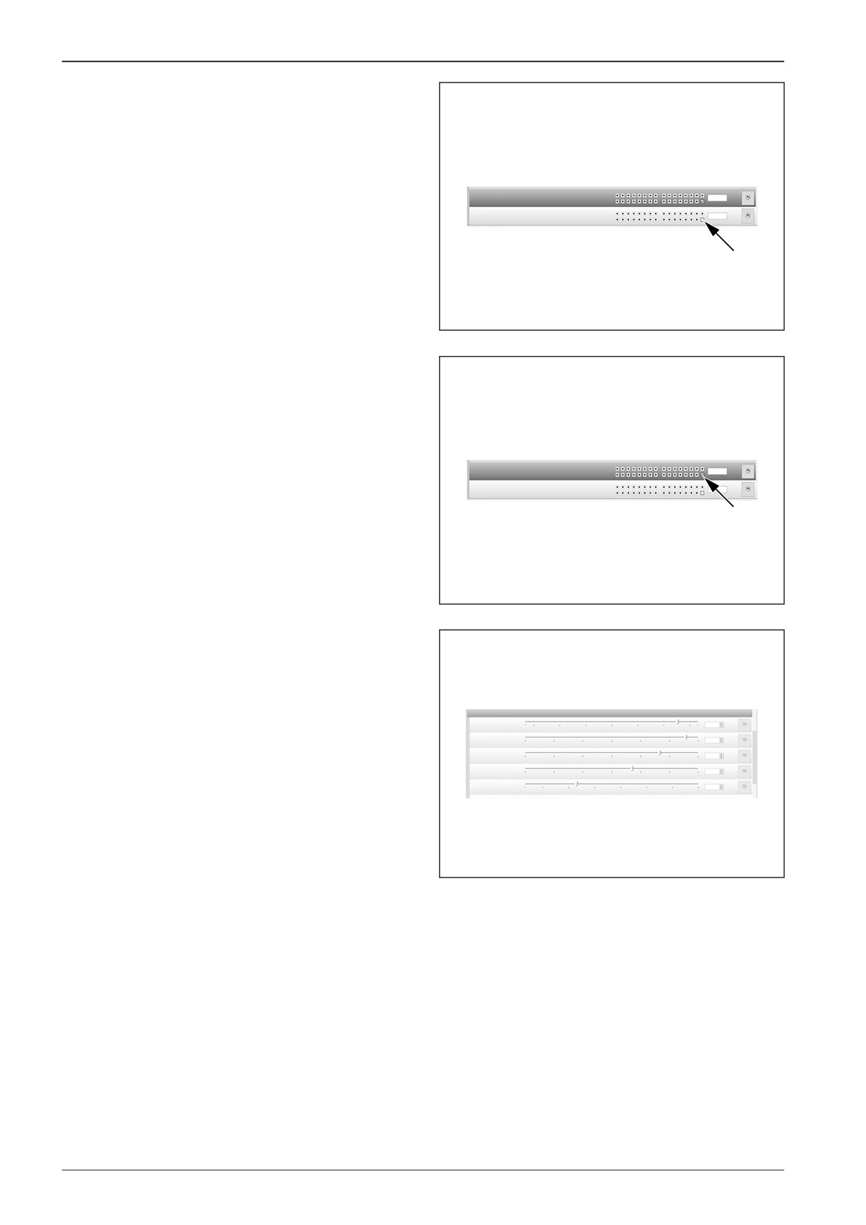
Confirm the setting by checking and subsequent unchecking
the box in “1.7.8 Set value”.
A short sound signal is heard.
1.7.7 Propel pump calib
1
STD
1.7.8 Set value
0
STD
D451C029
After finishing calibration uncheck the last box in “1.7.7 Propel
pump calib”.
1.7.7 Propel pump calib
1
STD
1.7.8 Set value
0
STD
D451C026
The changed values are visible at the next connection of the
computer to the machine.
Check the parameters; the values must be slowly increasing.
1.7 Calibration drive
Note
1.7.1 Propel pump max rev
1,954
mV
200
600
900
1200
1500
1800
2200
STD
The result of calibration should be that when the working speed
1.7.2 Propel pump min rev
2100
2200
2300
2400
2500
2600
2700
2,655
mV
STD
is started, it slowly decreases without any speed increase by the
1.7.3 Propel pump stop
2200
2300
2400
2500
2600
2700
2800
2,664
mV
STD
1.7.4 Propel pump min fwd
2,669
mV
travel controller or by turning the paving speed selector. The
2300
2400
2500
2600
2700
2800
2900
STD
machine must not move if the travel controller is in the maxi-
1.7.5 Propel pump max fwd
2800
3000
3300
3600
3900
4200
4500
4800
3,389
mV
STD
mum position for the forward travel and at the same time the
paving speed selector is in the “min” position.
451C034
212
F80W
WORKSHOP MANUAL
15.4
Control unit A2
When replacing the control unit, the machine compatibility with
the software in the control unit must be consulted with the DY-
NAPAC Technical Support.
Software
AFW150-2 v1.2.2
D451650
15.4.1
Dismounting the control unit A2
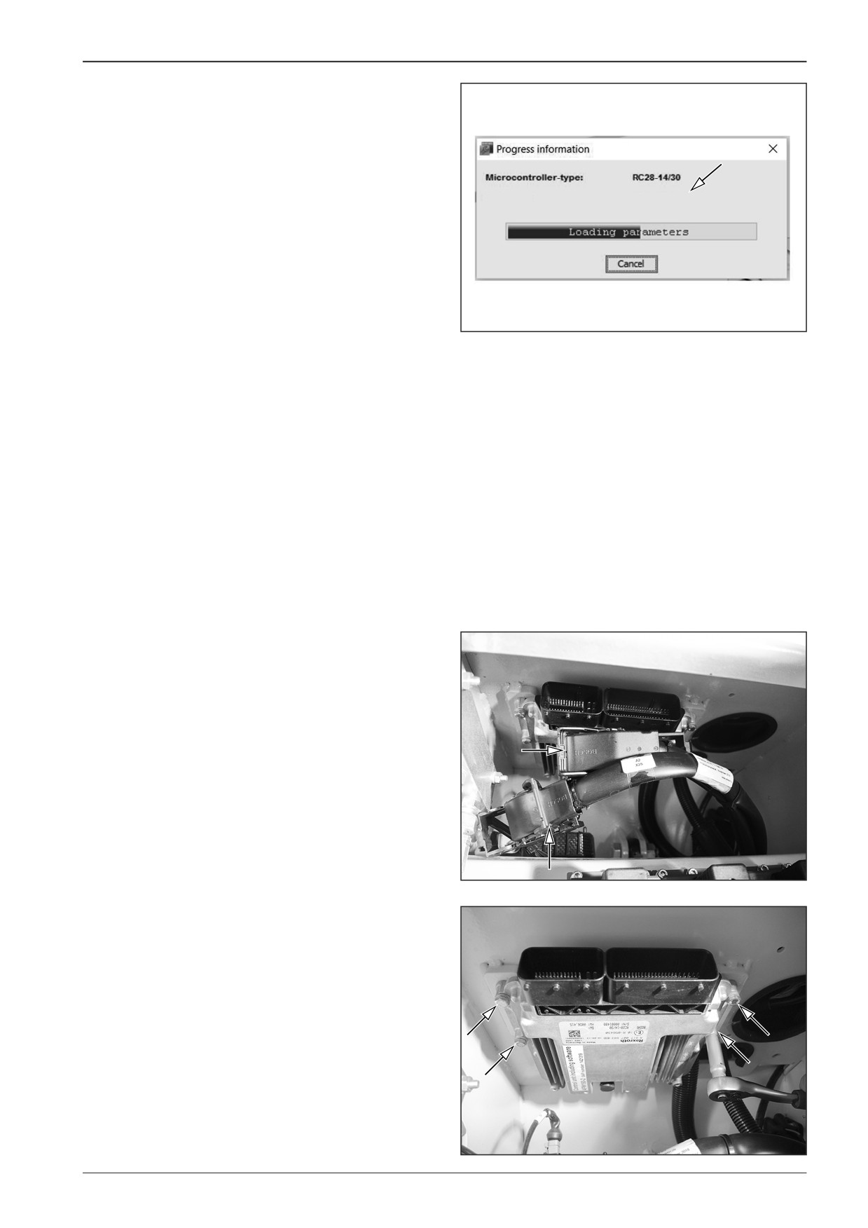
Dismount the control unit from the machine with the switched
off battery disconnecter and with the closed gas bottle valve.
Unlock and disconnect connectors X34 and X35 of the control
unit.
D451653
Remove the screws (4x).
DD451001
F80W
213
15
Wiring
15.5
Display unit
If the display does not respond when the key is turned to the “I”
position, check:
•
fuse F7 (2 A)
•
wiring between the ignition box S3 (pin 15) and the display
connector X33 (pin 1)
•
wiring between the battery disconnecter and the connector
X33 (pin 5)
•
connection of connectors X33 and X40 to the display.
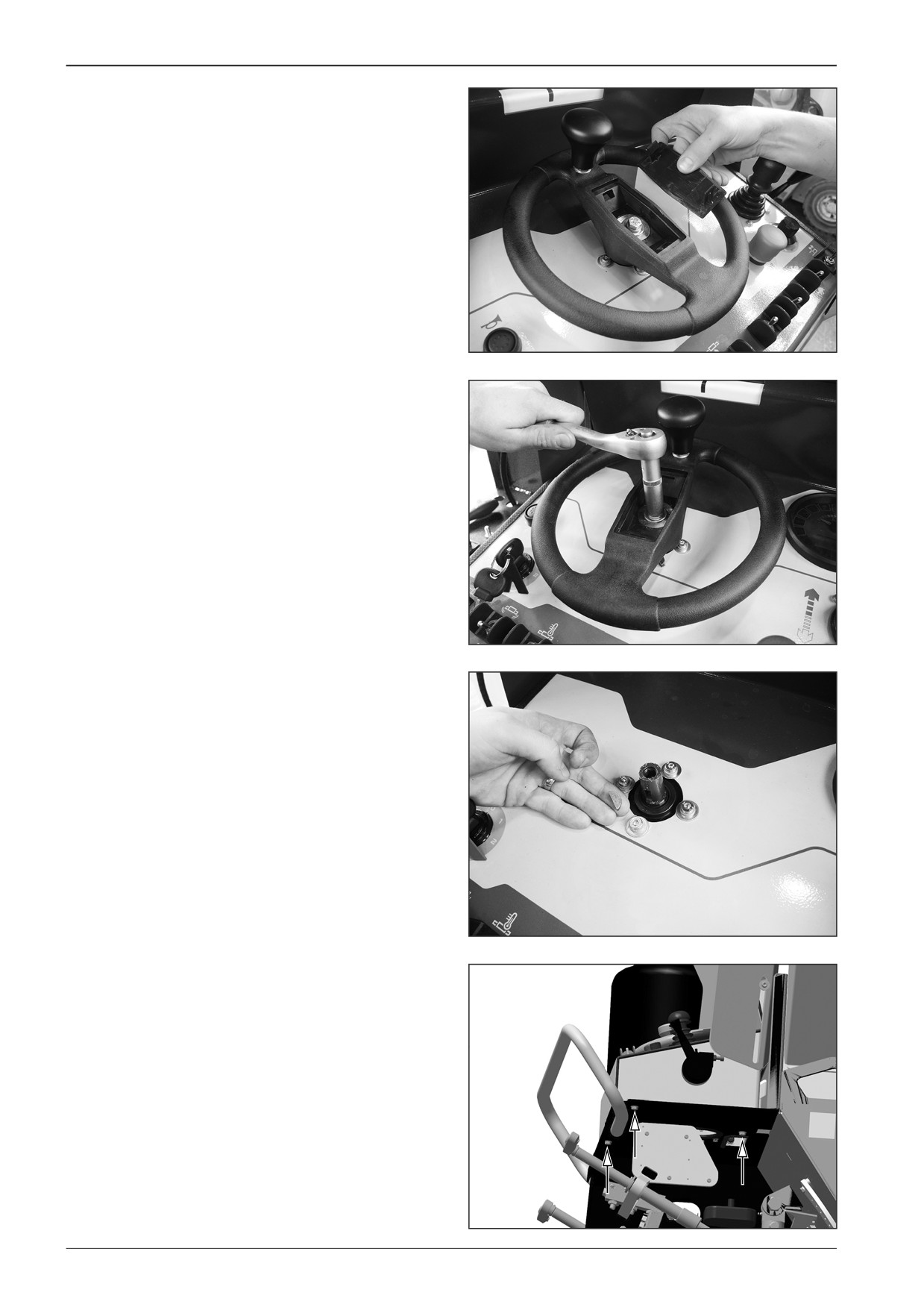
15.5.1
Dismounting the display
Dismount the display from the machine with the switched off
battery disconnecter and with the closed gas bottle valve.
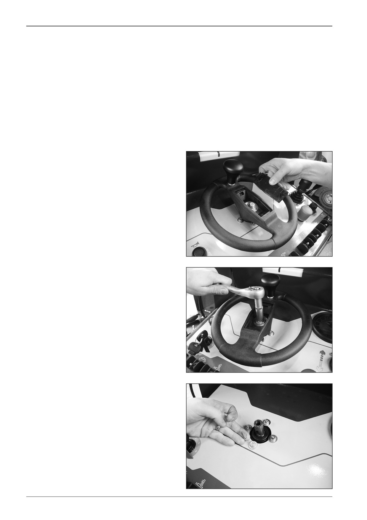
Remove the steering wheel.
•
Remove the cover.
D451461
•
Remove the screw.
D451462
•
Take out the steering wheel and remove the screws.
D451463
214
F80W
WORKSHOP MANUAL
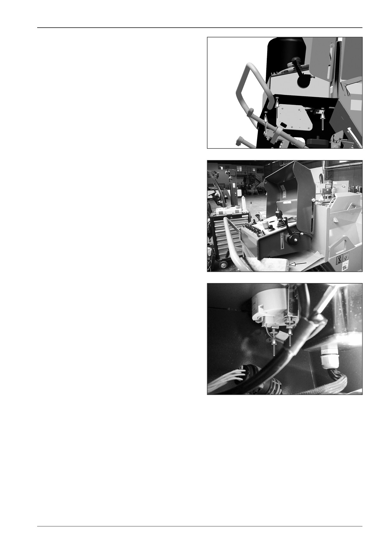
Remove the control panel.
•
Remove the screws (3x).
DD451004
Support the control panel.
DD451003
Remove the lock nuts (2x).
Note
Proceed in the reverse order when reassembling the display.
DD451005
F80W
215
15
Wiring
15.6
Travel controller
When calibrating the travel controller proceed according to
Chapter 15.3.2.
15.6.1
Dismounting the travel controller A4
Dismount the travel controller from the machine with the
switched off battery disconnecter and with the closed gas bottle
valve.
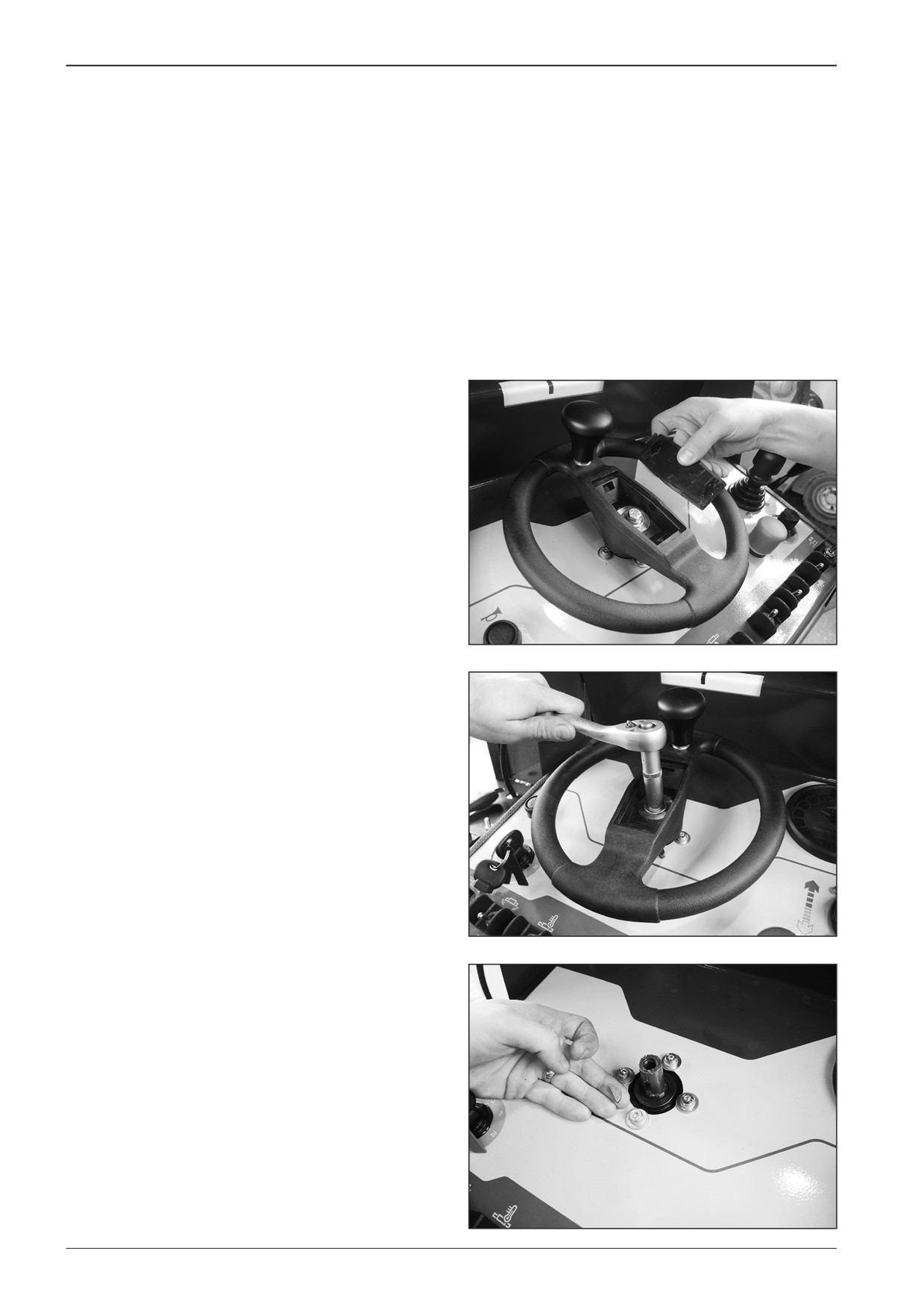
Remove the steering wheel.
•
Remove the cover.
D451461
•
Remove the screw.
D451462
•
Take out the steering wheel and remove the screws.
D451463
216
F80W
WORKSHOP MANUAL
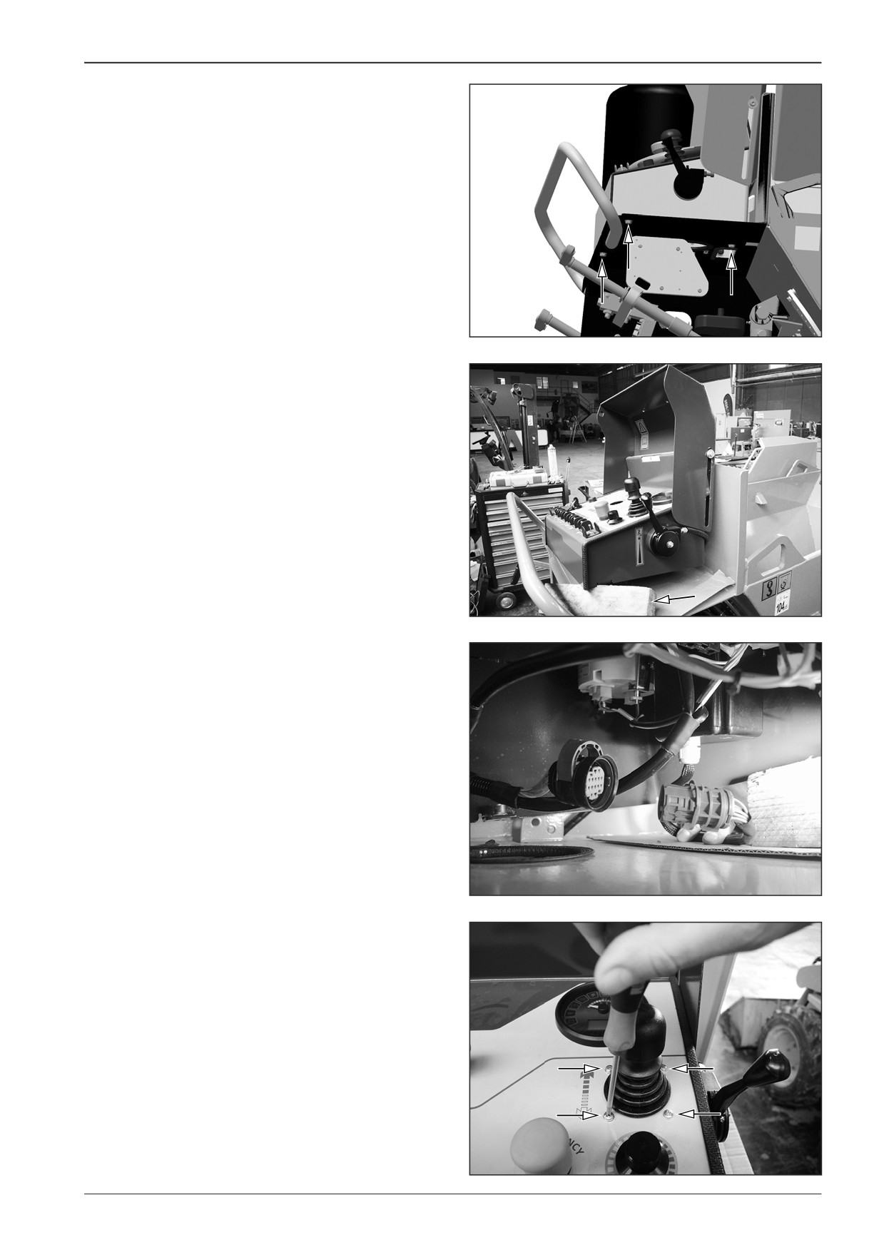
Remove the control panel.
•
Remove the screws (3x).
DD451004
Support the control panel.
DD451003
Disconnect the connector X36.
DD451012
Remove screws of the travel controller (4x).
Note
Proceed in the reverse order when reassembling the unit.
After reassembling the unit perform calibration according to
Chapter 15.3.2.
DD451013
F80W
217
15
Wiring
15.7
Paving speed selector
•
In case of a fault of the paving speed selector, the display
shows error message F12.
•
When calibrating the paving speed selector proceed accord-
ing to Chapter 15.3.2.
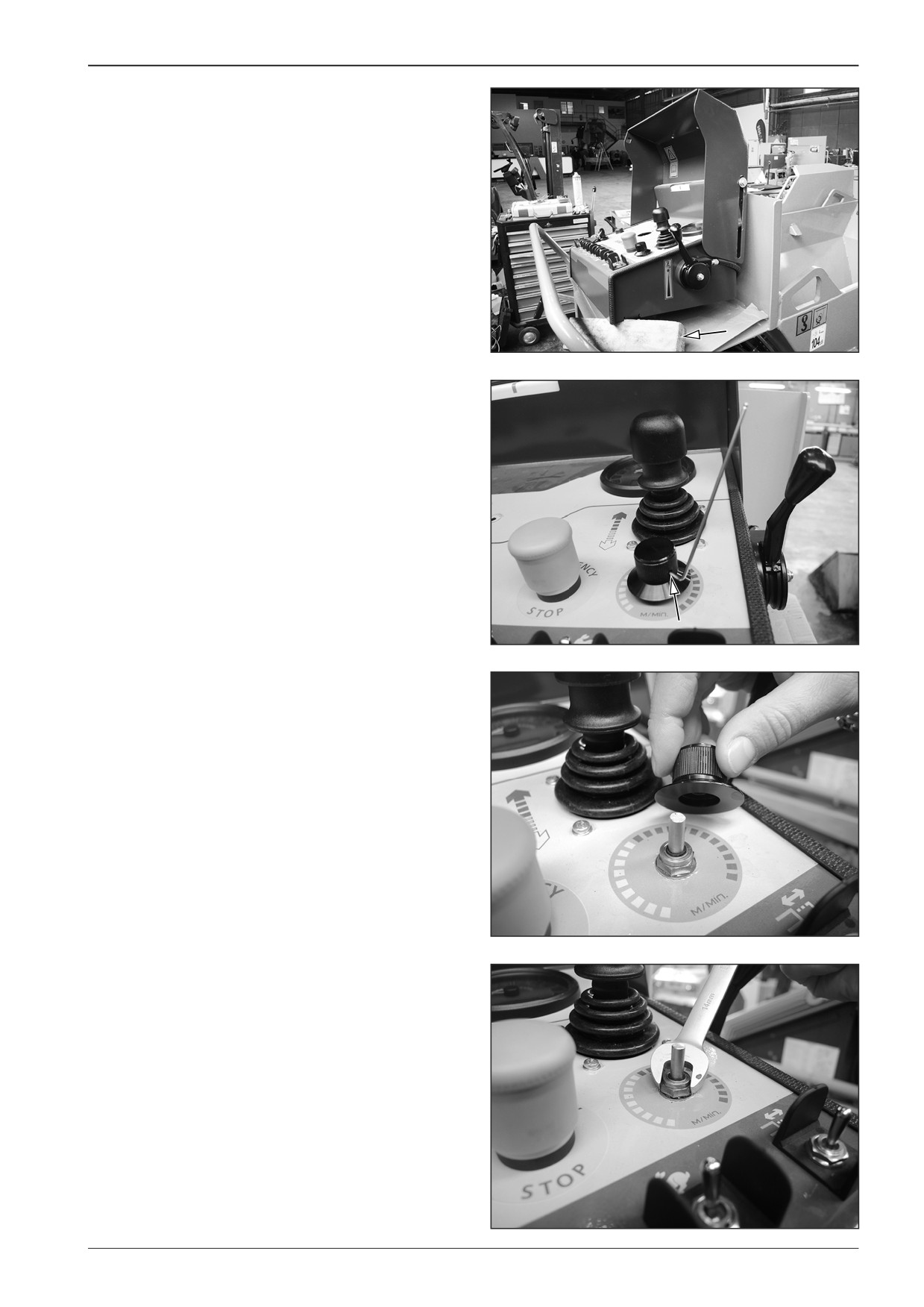
15.7.1
Dismounting the paving speed selector
Dismount the paving speed selector from the machine with the
switched off battery disconnecter and with the closed gas bot-
tle valve.
D451461
Remove the steering wheel.
•
Remove the cover.
•
Remove the screw.
D451462
•
Take out the steering wheel and remove the screws.
D451463
Remove the control panel.
•
Remove the screws (3x).
DD451004
218
F80W
WORKSHOP MANUAL
Support the control panel.
DD451003
Remove the paving speed selector regulator.
- Loosen the screw.
DD451014
DD451015
Remove the nut.
DD451016
F80W
219
15
Wiring
Slightly pull out the selector and disconnect the X37 connector.
Note
Proceed in the reverse order when reassembling the unit.
After reassembling the unit perform calibration according to
Chapter 15.3.2.
DD451017
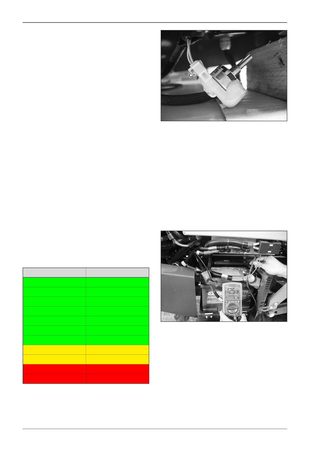
15.8
Battery
Measuring the battery voltage.
Battery status
Battery voltage
Battery charge status
12.6+ V
100%
12.5 V
90%
12.42 V
80%
12.32 V
70%
DD451020
12.20 V
60%
12.06 V
50%
11.9 V
40%
11.75 V
30%
11.58 V
20%
11.31 V
10%
10.5 V
0%
220
F80W
WORKSHOP MANUAL
16
Appendices
F80W
221
16
Appendices
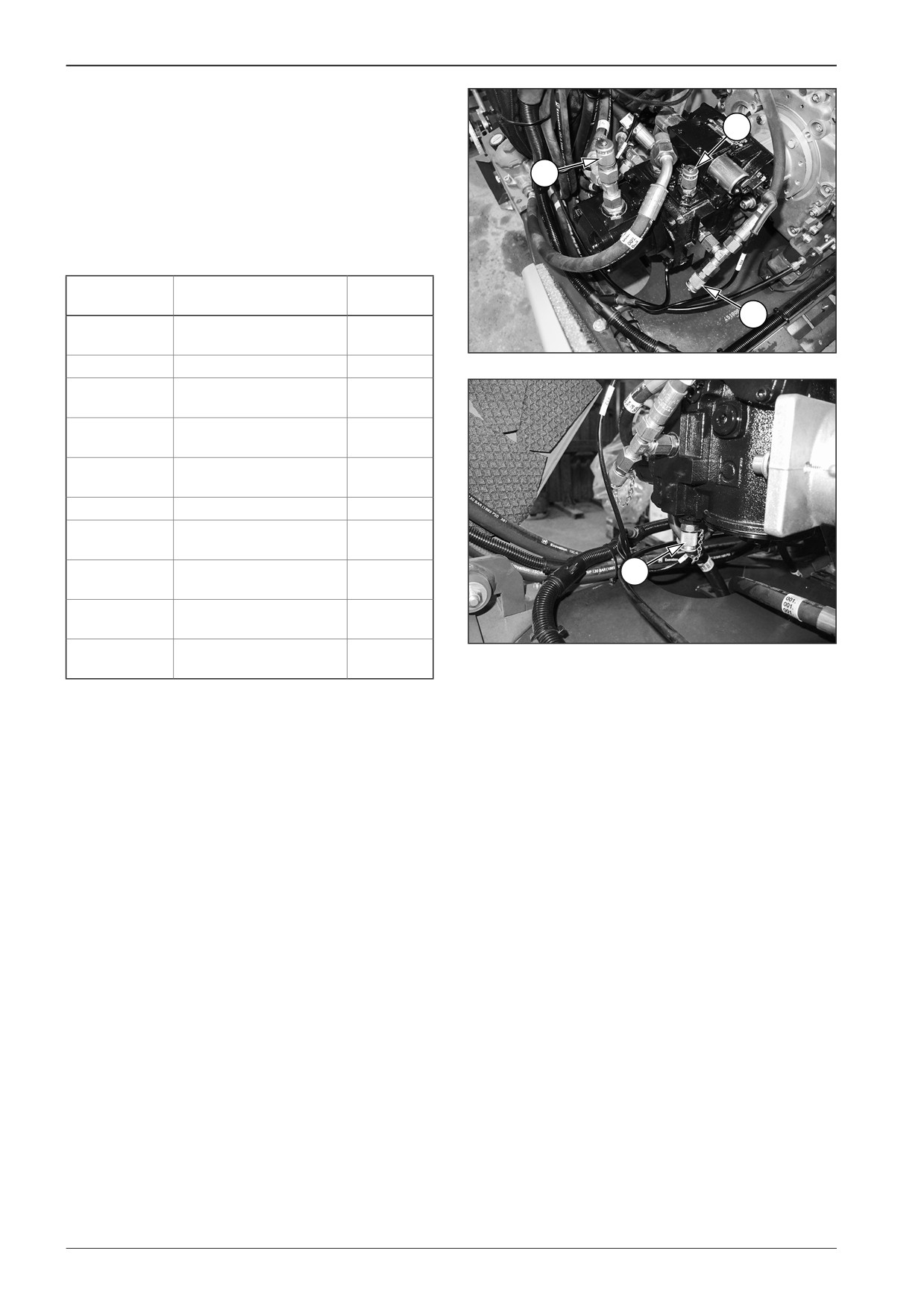
16.2.1
Measuring points of the hydraulic circuit
The table shows the list of the hydraulic circuit measuring points
2
located on the machine.
1
Note
See the procedure for measuring the pressure in the hydraulic
circuit in the workshop manual delivered upon a special order.
Mode
Pressure
(bar)
3
Measuring
Conveyor (maximum
150±5
point no. 1
speed)
D451709
Auger (maximum speed)
150±4
Screed lifting (maximum
50±5
speed)
Screed extension
50±5
(maximum speed)
Vibrations + travel
50±5
(maximum speed)
Steering (maximum speed)
50±5
Measuring
Forward travel
150±10
point no. 2
Measuring
Refilling pressure
20±2
4
point no. 3
(maximum speed)
Refilling pressure (idle
22+4/-2
speed)
D451710
Measuring
Reverse travel
150±10
point no. 4
230
F80W
WORKSHOP MANUAL
10
2
12 V
5 A
12
7
11
2
1
1
1
6
4
3
5
8
3
4
3
9
8
D451900
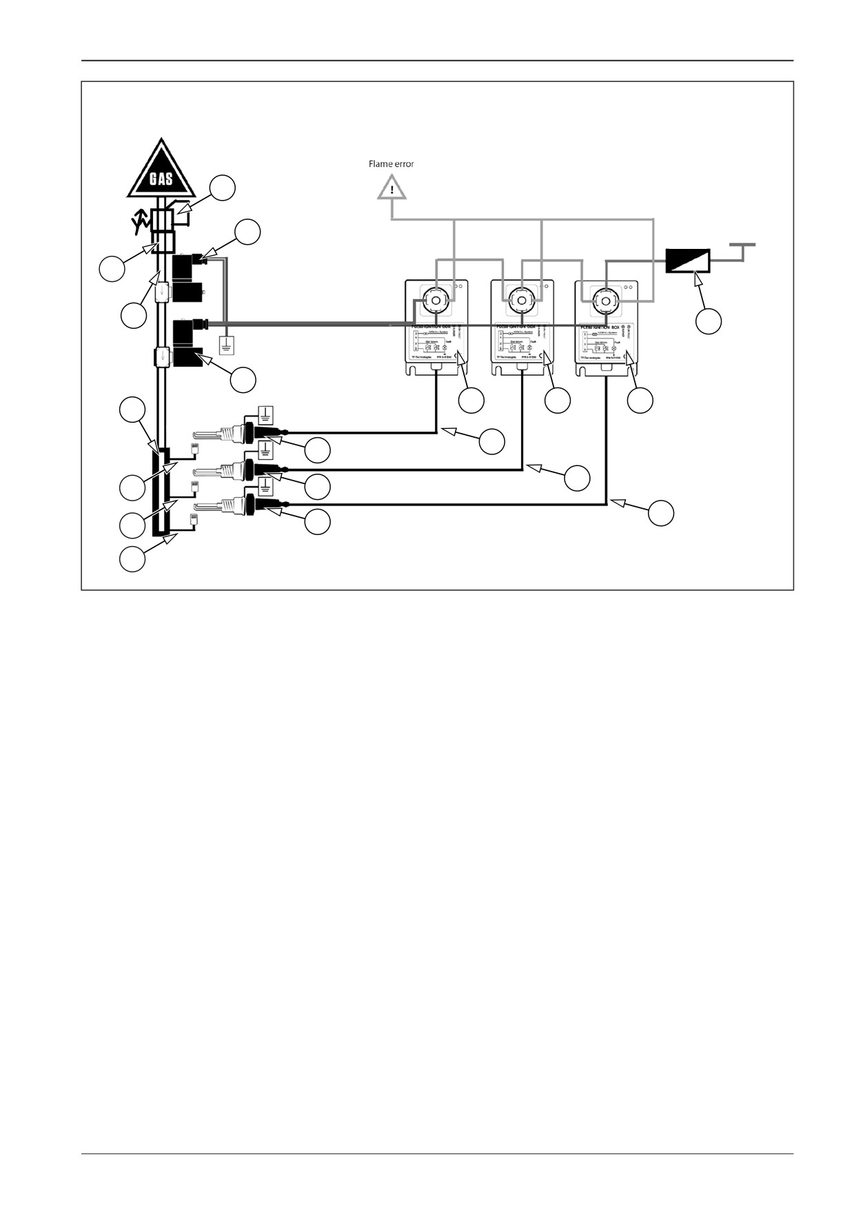
16.3
Screed gas heating system diagram
Legend:
1
Automatic screed heating ignition boxes
2
Gas supply solenoid valves
3
Spark plugs
4
Cables
5
Cable
6
Gas supply manifold
7
Gas hose
8
Gas hose
9
Gas hose
10
Reducing valve
11
Screed heating fuse, 5 A
12
Safety valve
F80W
231