BESSER DYNAPAC 3 AT A TIME (466361F9710US). OPERATION / MAINTENANCE MANUAL - page 5
SECTION 10
TROUBLESHOOTING
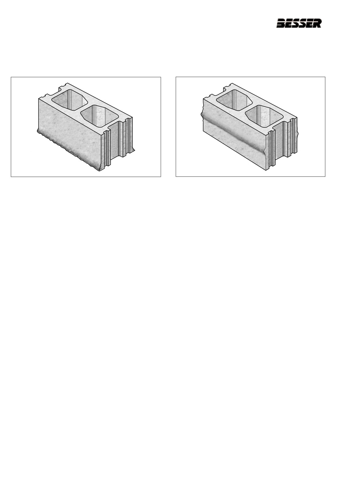
10.2.7 BOTTOM EDGE CRUSHED
10.2.8 BLOCK CRUSHED DURING STRIPPING
a. Check spring opening. (section 5)
a.
Increase strip delay time. (section 9)
b. Check delay time. (section 8 and 9)
b.
Check spring opening. (section 5)
c. Check stripper head alignment. (section 5)
c.
Check moisture content of concrete.
d. Check pallet receiver rubbers.
d.
Check for excess feed. Decrease feed time and
lower autofeed if necessary.
e. Check for build up on bottom of mold.
e. Check vibrator brakes.
f.
Check for build up on pallets.
f.
Check pallet delivery and timing.
g. Check for spillage on pallet.
g. Check air compaction setting.
h. Check rubbers on cutoff bars.
i.
Check the mix (can be too dry).
j.
Check the air compaction setting (too much force).
k. Make sure pallet is against bottom of mold.
10-8
466361F9710US F1 29OC99

SECTION 10
TROUBLESHOOTING
10.2.9 CORE BAR CRACK
10.2.10 CRACKING AT PALLET SIDE
a. Check vibrator brake settings.
a.
Check for loose core assembly.
b. Check vibrators shaft speeds.
b.
Check for bent core assembly.
c. Check for loose cores.
c.
Check pallet receiver frame for level.
d. Check vibrator sheave alignment.
d.
Check pallet receiver rubbers. Pallet may be mov-
ing during finish time (it may require pallet snub-
e. Check pallet guides. Rear guides may have a
bers).
groove worn so pallets stick during stripping opera-
tion (this may not apply to V4).
e.
Check pallet guides.
f.
Check feed and finish time (it may need more).
f.
Check core bars for material build-up.
g. Check for material build-up on core bars or core
g.
Check for thick and thin pallets.
assemblies.
h. Check vibrator brakes (may be slipping).
h. Check mix (it can be too dry).
i.
Check for material between pallet and pallet receiv-
er rubbers.
j.
Pallet receiver and stripper head alignments.
10-9
466361F9710US F1 29OC99
SECTION 10
TROUBLESHOOTING
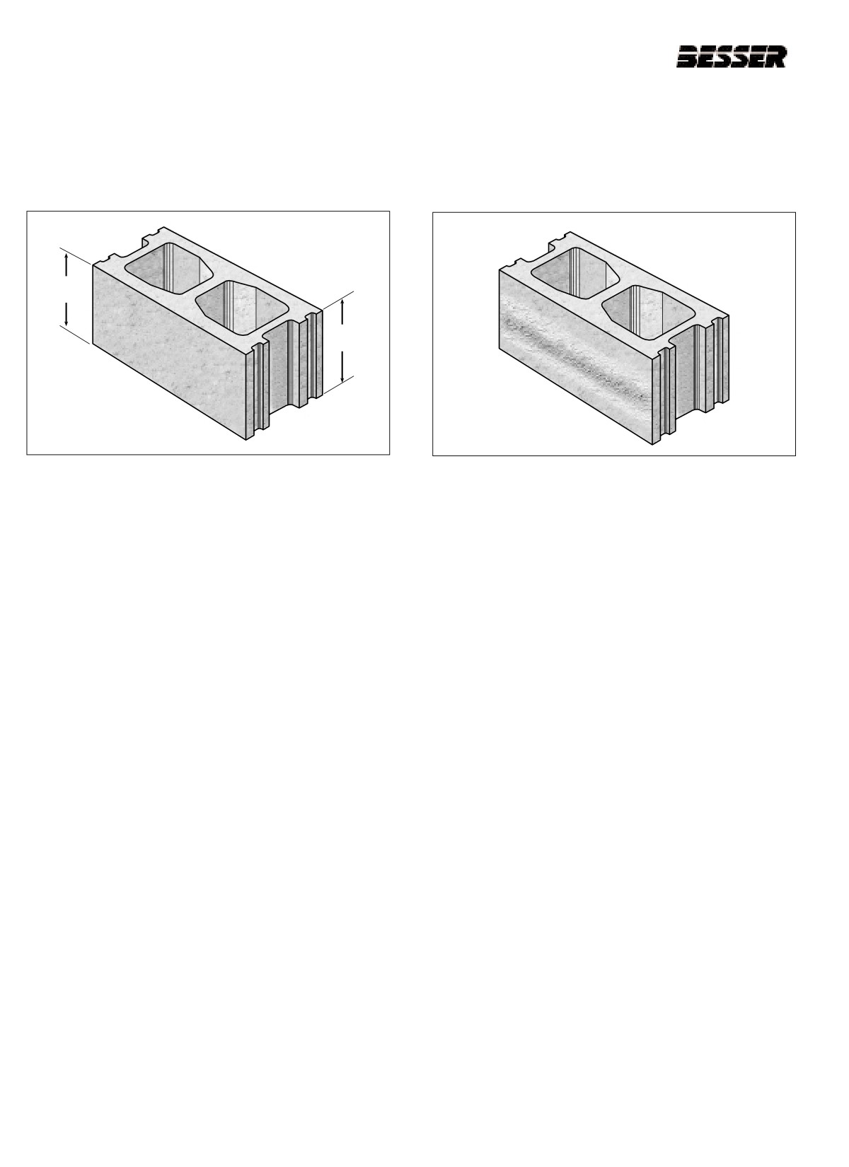
10.2.11 BLOCK HEIGHT NOT CORRECT
10.2.12 COARSE TEXTURE IN MIDDLE OF
FRONT TO REAR
BLOCK FACE
7 5/8
7 7/16
a. Check pallet receiver frame for level (see section
a. Check vibrator shaft speeds.
5.4)
b. Check material for coarse aggregate.
b. Check stripper head frame in relation to pallet
receiver frame alignment.
c. Check (generally increase) feed time setting.
c. Check stripper head for level.
d. Check material, could be too wet.
d. Check mold for 5/8" dimension off mold throat.
e. Check autofeed, make sure it's turned on.
e. Check for loose stripper shoe or plunger.
f.
Check for material segregation.
f.
Check agitator grid (see section x.x).
g. Check vibrator motor rotation.
g. Check delay time.
H. Material segregation in machine hopper.
10-10
466361F9710US F1 29OC99
SECTION 10
TROUBLESHOOTING
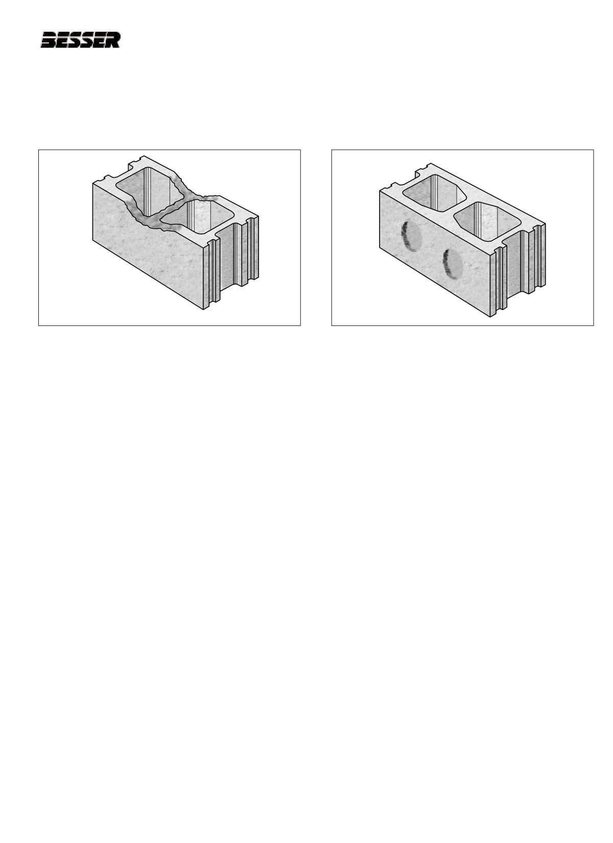
10.2.13 BLOCK NOT FILLED PROPERLY
10.2.14 FACE SHELLS SUCKED IN AT
COMPLETION OF STRIPPING
a. Check core vents, may be plugged.
a. Check agitator grid for build up.
b. Material too wet, moisture content variation.
b. Check agitator grid to make sure it is turned on.
c. Check for worn division plates.
c. Material too wet and there may be moisture
variations.
d. Check for loose core assembly.
d. Check that autofeed is on automatic.
e. Check stripping speed.
e. Check hopper gate setting.
f.
Check admix.
f.
Check if there are chunks in feedbox.
g. Check for frozen aggregate.
g. Check feed time.
h. Check core valve springs.
10-11
466361F9710US F1 29OC99
SECTION 10
TROUBLESHOOTING
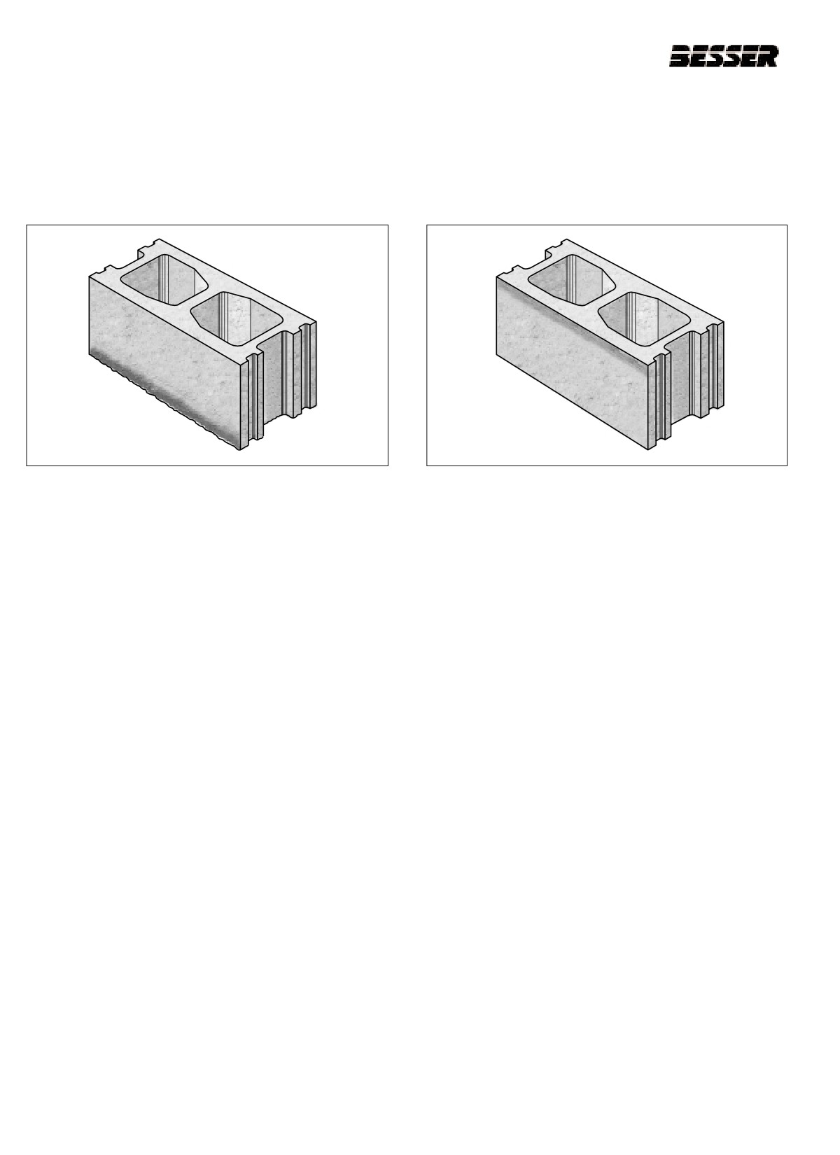
10.2.15 COARSENESS ON BOTTOM OF BLOCK
10.2.16 HAIRLINE CRACKING AND PULLING
LEAVING A BAD EDGE
AT TOP OF BLOCK ON COMPLETION
OF STRIPPING
a. Check pallet receiver rubbers.
a.
Check spring opening to assure height pins stay
together during strip.
b. Check if pallet moves during vibration.
b. Check to make sure stripper shoe protrudes
c. Check vibrator weights, may have to change to
through bottom of mold at completion of strip.
larger or smaller vibrator weights.
c. Check adjustment for stripping.
d. Check mold for loose parts.
d. Check division plates for wear.
e. Check stripper head alignment.
e. Check for loose stripper shoes.
f.
Check for material segregation.
f.
Check moisture content of mix. It may be too wet.
g. Check for build up on pallets or mold.
h. Check for core spillage on pallet.
i.
Check moisture content of mix. It may be to dry.
j.
Check vibrator shaft rotation.
k. Make sure pallet is against bottom of mold.
10-12
466361F9710US F1 29OC99
SECTION 10
TROUBLESHOOTING
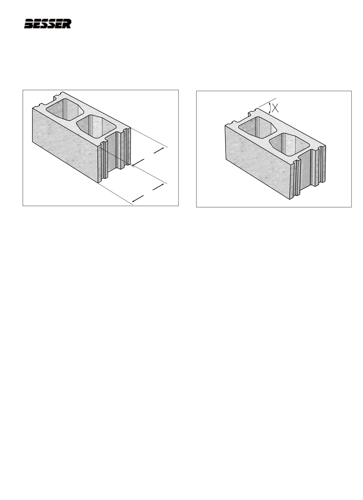
10.2.17 BLOCK WIDER AT TOP THAN AT
10.2.18 BLOCK OUT OF SQUARE (NOT 900
BOTTOM
ON EACH CORNER)
900
7 3/4
7 5/8
Note: There are no visible cracks on the blocks.
a. Check mold assembly for wear.
a. Check block handling during movement to curing
b. Check all mold parts for excessive wear.
kilns.
c. Check block delivery on machine.
b. Check block delivery on machine.
d. Check curing cycle (preset, steam, etc.).
c. Check stripping adjustment.
d. Check mold assembly for wear.
e. Check curing cycle (preset & steam conditions).
f.
Check admix.
10-13
466361F9710US F1 29OC99
SECTION 10
TROUBLESHOOTING
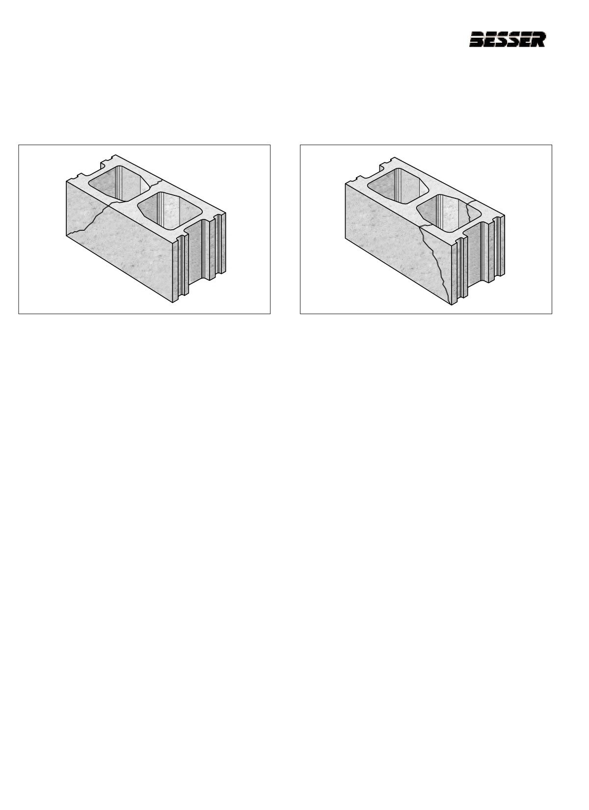
10.2.19 DIAGONAL CRACK AT REAR OF
10.2.20 DIAGONAL CRACK AT FRONT OF
BLOCK
BLOCK
a. Pallet setting on block moving bars may be too late.
a. Check if pallet hit stop on front delivery too hard.
b. Check fork lift bumping rack on Besser-Matic.
b. Check fork lift bumping rack on Besser-matic.
c. Check if pallet is setting down evenly on front deliv-
c. Check if pallet is not setting down evenly on front
ery conveyor.
delivery conveyor.
d. Check for loose core.
d. Check for loose core.
e. Check of loose plunger.
e. Check for loose plunger.
f.
Check mix design.
f.
Check mix design.
g. Check vibrator weights.
g. Check for wrong vibrator weights.
10-14
466361F9710US F1 29OC99
SECTION 10
TROUBLESHOOTING
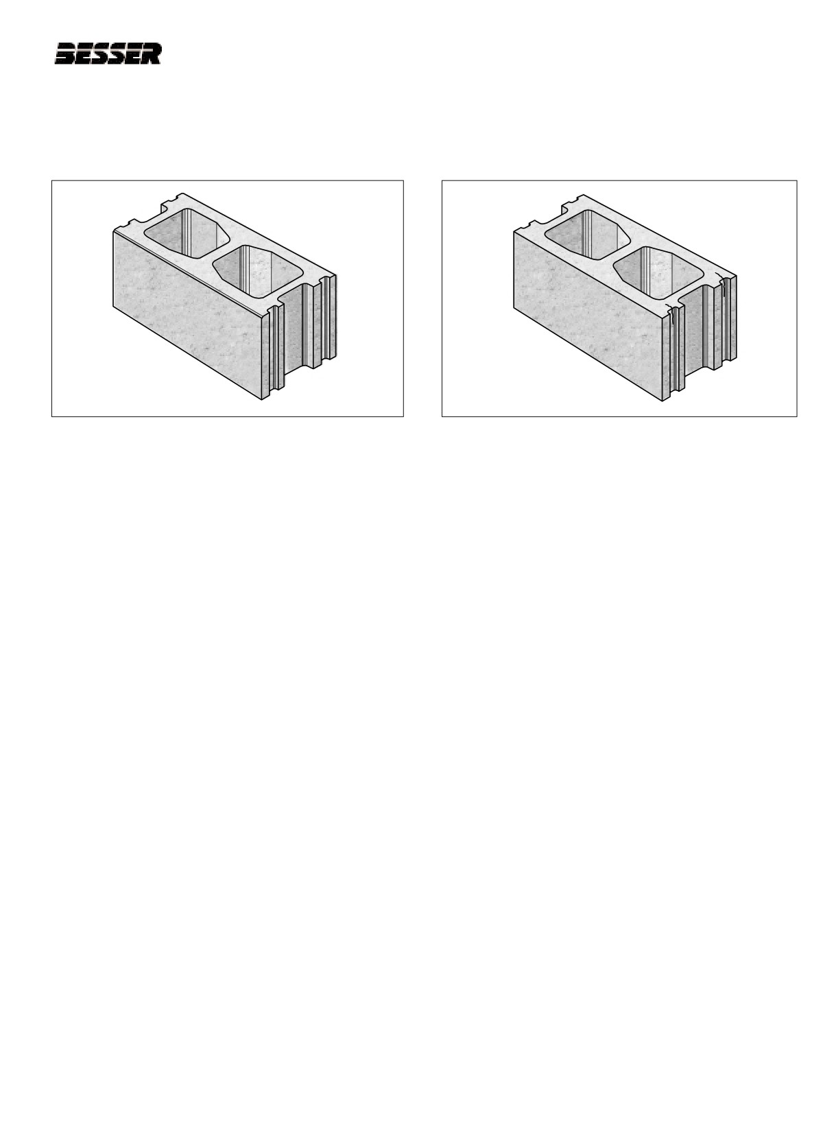
10.1.21 FEATHER-EDGE AT TOP OF UNIT
10.1.22 CRACK IN MORTAR GROOVE
a. Check alignment of stripper shoes.
a. Check vibrator brakes.
b. Check for worn plungers and mold parts.
b. Check for loose end liner.
c. Check Mix design and mixing procedure.
c. Check for worn end liner.
d. Check stripping adjustment.
d. Pallet snubbers may be necessary.
e. Check for mold shifting.
e. Check vibrator shaft speeds.
f.
Check for loose mold parts.
f.
Check for loose mold parts.
g. Check stripper head alignment.
g. Check stripping adjustment.
h. Check vibration.
h. Check moisture content of mix.
i.
Check vibrator motor brake adjustments.
i.
Check mix design.
j.
Check admixture in batch.
10-15
466361F9710US F1 29OC99
SECTION 10
TROUBLESHOOTING
10-16
466361F9710US F1 29OC99
SECTION 11
MAINTENANCE
SECTION 11
MAINTENANCE
11.1
PREVENTIVE MAINTENANCE
Correct maintenance is largely a matter of good judgment on the part of the operator in charge. The DYNA-
PAC, like any other machine, will do the work required just as long as it is properly cared for. A good preven-
tive maintenance program based on the recommendations below will extend the machine’s life at a high level
of performance.
Check the following procedures daily and every time a product or mold change is done.
COMPONENT
REF.1
CHECK FOR
TOLERANCE2
ACTION
HOURS3
Upper and lower height stops
5.22
Loose clamp / wear
see torque chart
repair
400
Lower height stops wire
5.22
Loose / broken
0
repair / replace
400
Spring link assembly Spring opening
5.33
Gap as mold touches throat
1/16" [1.5mm]
adjust
400
Pallet receiver rubbers
4.14
All rubbers same height
max:015" [.38mm]
replace
400
Mold
5.9
Centered (after vibration)
± .030" [.76mm]
adjust
400
Mold locks and liner
5.2
Wear
0 to .125" [3mm]
replace
1000
.020" ± .030"
Mold lock liner
5.2
Clearance
adjust
1000
[.51mm ± .76mm]
every
.030" ± .010"
Apron plate
5.17
Clearance to mold
adjust
mold
[.76mm ± .25mm]
change
every
.125" ± .010"
Apron plate
5.17
Height above mold
adjust
mold
[3mm ± .25mm]
change
Pallet receiver frame -
.020" ± .005"
every
5.16
Clearance
adjust
guide liners
[.51mm ± .13mm]
week
Stripper head frame -
.020" ± .005"
every
5.28
Clearance
adjust
guide liners
[.51mm ± .13mm]
week
Table 11.1
PREVENTIVE MAINTENANCE TABLE
1 The "REF." column refers you to the figure in this manual where the component is illustrated and
where adjustment instructions is given.
2 If TOLERANCE is not respected, proceed to ACTION.
3 Hours of operation.
11-1
466361F9710US F1 29OC99
SECTION 11
MAINTENANCE
11.2
SERVICE AND REPAIRS
11.2.1
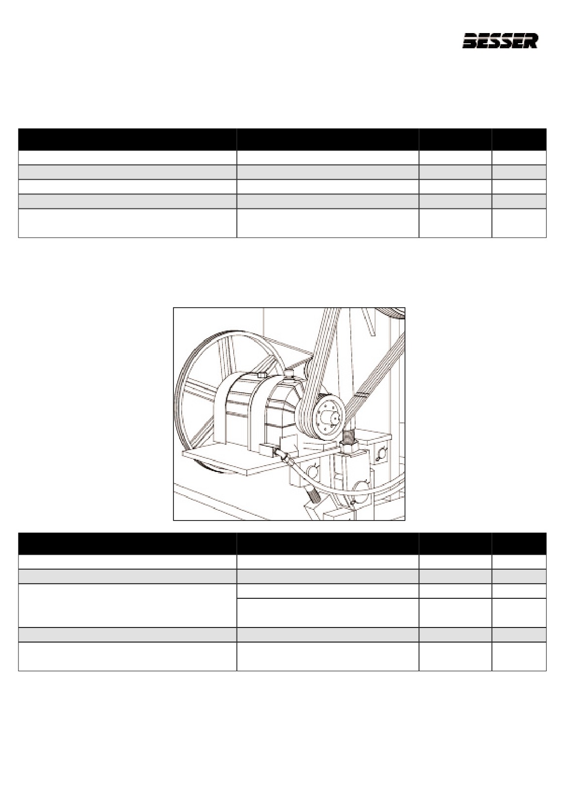
DRIVE MOTOR (not illustrated)
COMPONENT
CHECK FOR
ACTION
HOURS
Mounting bolts
Recommended torque
torque
installation
Bearings
.002 [.05mm] radial move
repair / replace
4000
Lubrication
lubricate
2000
Sheave
Wear - Match with gauge #112541
replace
400
Surface contamination, wear, cuts, cracks
Belts
replace
400
Match with gauge #112541
Table 11.2
11.2.2 BESCODYNE CLUTCH/BRAKE UNIT (FIGURE 11.1)
Figure 11.1
COMPONENT
CHECK FOR
ACTION
HOURS
Input sheave #112339F2280
Match with gauge #112541
torque
installation
Output sheave #112339F6080
Match with gauge #112541
repair / replace
4000
Oil - 10 quarts
check level
weekly
Lubrication
Oil - Use Mobil Automatic Transmission Fluid
change
3 weeks
ATF-210 (Type “F”) or equivalent
Disc
Centered (after vibration)
replace
400
Surface contamination, wear, cuts, cracks
Belts
replace
400
Match with gauge #112541
Table 11.3
11-2
466361F9710US F1 29OC99
SECTION 11
MAINTENANCE
11.2.2 BESCODYNE CLUTCH/BRAKE UNIT
(continued)
1. Check the disc wear surfaces for scoring, galling or
evidence of uneven wear.
11.2.2.1 CHECKING THE OIL LEVEL
2. Check the clutch and brake plates for scoring or
Every week or until experience dictates otherwise,
galling. Make sure they are flat. If a perceptible
check the oil level. Always check the oil level with the
ridge is worn in any of the drive plates, replace all of
drive at room temperature and while it is not running.
the drive plates and friction discs as a complete set.
The drive has an oil sight gauge located at the output
3. Carefully check the piston and bore surfaces for
end of the drive. The oil level is to be at the center of
nicks, scratches, scoring or other damage which
the gauge.
would affect operation or cause leakage.
4. Pay particular attention to Wear Sleeve (#250),
11.2.2.2 CHANGING THE OIL
Mating Ring (#4) and shafts in the area of rotary
seals. Check for nicks or scratches which would
IMPORTANT : Open the disconnects to the drive
cause leakage. Replace any damaged parts.
motors before attempting to change the oil.
5. It is not necessary to remove the ball bearings to
Every three months, completely drain the oil from the
check their operation. Slowly rotate the free race of
drive using the drain plugs provided. If the oil sight
each bearing by hand checking to see if it turns
gauge is dirty, it should be removed and cleaned.
freely without rough or flat spots.
Reinstall the drain plugs and refill the drive to the cen-
ter of the sight gauge with fresh oil.
11.2.2.5 REPAIR AND REPLACEMENT
Note: Do not overfill the drive unit. Excess oil will cause
A fine stone or crocus cloth may be used to remove
the unit to overheat.
minor surface defects from parts as long as the operat-
ing or sealing action of the part is not affected. The use
of coarser abrasive or other machining methods should
11.2.2.3 TYPE OF OIL
not be attempted. Otherwise, damaged parts should be
replaced.
Use only Mobil Automatic Transmission Fluid ATF-21 0
(type
“F’) or Mobil Multi-purpose Automatic
Replacement is recommended also for the following, as
Transmission Fluid for most drives. Other fluids may be
applicable:
specified for special applications. Always use the type
of fluid specified on the Name Plate.
1. Replace all O-Rings, Liners, Gaskets and Oil Seals
removed during the course of disassembly.
11.2.2.4 CLEANING AND INSPECTION
2. Replace Clutch or Brake Discs and Drive Plates as
complete sets only.
Clean metal parts in a suitable solvent and dry in a
stream of low pressure compressed air. The Clutch and
Brake Drive Plates can be cleaned in solvent, but DO
11.2.2.6 BELTS (ref. table 11.3)
NOT clean the Clutch and Brake Friction Discs in sol-
vent. Use only a clean, dry and lint-free rag to clean
Check wear and tension on input and output belts as
these Friction Discs. (Solvent will damage the resilient
described in table 11.3 (see figure 11.4 and 11.5).
paper-based friction material used on the Friction
R
Discs). Keep the Drive Plates and Friction Discs in the
Note: Refer to Bescodyne catalogue #502-03/20-001
same order as they were removed. After cleaning,
for more complete instructions on this unit.
inspect parts for cracks, distortion, scoring, nicks, burrs
or other damage would affect serviceability. Pay partic-
ular attention to the following:
11-3
466361F9710US F1 29OC99
SECTION 11
MAINTENANCE
11.2.2.7
PROCEDURE FOR CHECKING BRAKE
AND CLUTCH STACKS FOR WEAR.
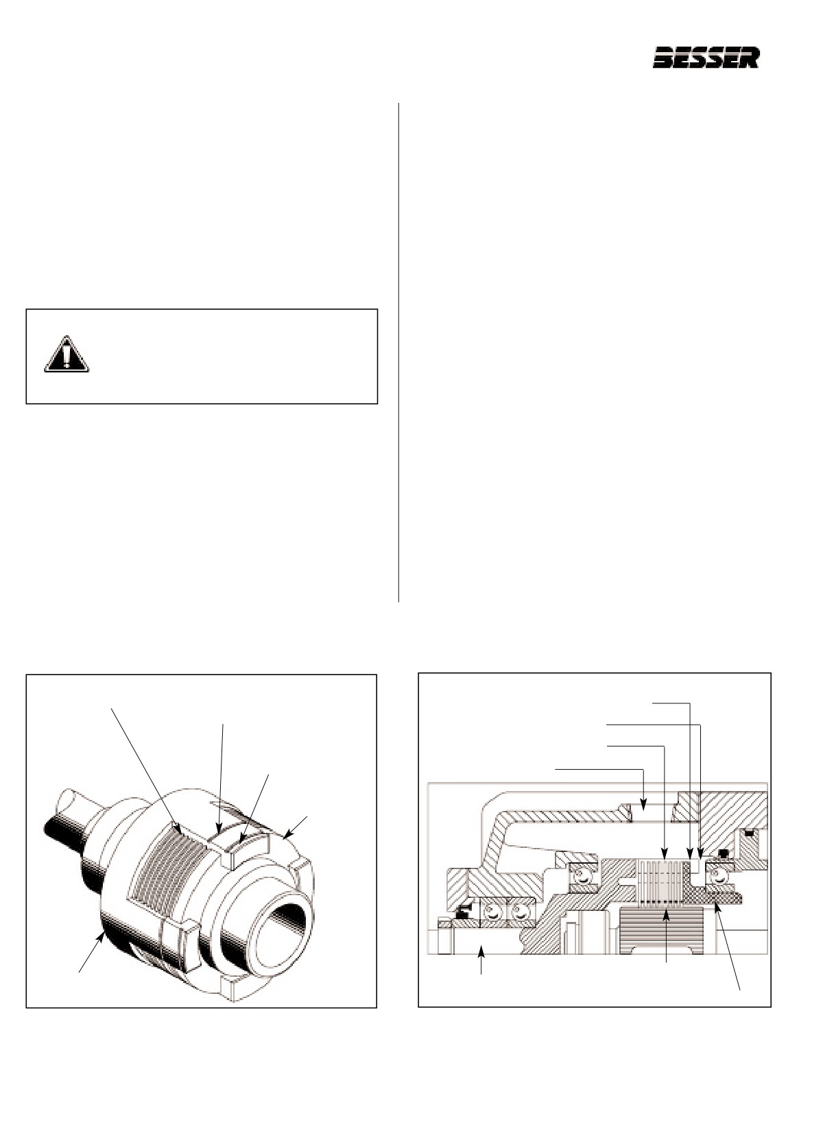
An easy procedure has been established to visually
If the rear surface of the clutch thrust plate (D) has
check the brake and clutch stacks for wear to deter-
moved up to or past the “stack wear” groove (A), the
mine whether or not they need to be replaced.
clutch stack needs to be replaced (see figure 11.2).
Two “stack wear” grooves (A) have been machined in
4. Exhaust the air pressure from the clutch port.
the input shaft (B) lugs to facilitate this visual check
(see figure 11.2)
B. BRAKE STACK WEAR
5. Apply air pressure to the brake port.
CAUTION: Disconnect and lock-out all
6. Using a flashlight, observe the clutch stack through
electrical power to the drive motor. This
the inspection port (A) (see figure 11.3).
step must be taken to avoid any possi-
bility of personal injury or damage to the
If the rear surface of the Thrust place (E) has moved
drive unit.
up to or past the “stack wear” groove #1, the brake
stack is worn and needs to be replaced.
1. Remove the inspection pipe plug from the top of the
input housing.
Note: Both the brake stack and the clutch stack can
individually be checked for wear. If either stack is
A. CLUTCH STACK WEAR
worn and needs to be replaced, both stacks
should be replaced as a complete set. Refer to
2. Apply air pressure to the clutch port.
service manual and repair parts for clutch/brake
drives (502-03/20-001) Besser catalog No.
3. Using a flashlight, observe the clutch stack (C)
437629F001, section 7 - DISASSEMBLY and
through the inspection port (see figure 11.2).
section 9 REASSEMBLY for brake and clutch
stack replacement.
Clutch stack (C)
Stack wear
Rear surface of pressure plate
groove (A)
“Stack wear” groove #1
“Stack wear” groove #2
Stack wear
groove (A)
Inspection port
Clutch thrust
plate (D)
Clutch stack
Input shaft (B)
Inspection port -B
Clutch thrust plate - E
Figure 11.2
STACK WEAR GROOVES.
Figure 11.3
BRAKE AND CLUTCH STACKS FOR WEAR.
11-4
466361F9710US F1 29OC99
SECTION 11
MAINTENANCE
11.2.2.8 BESCODYNE UNITS SERVICE TIPS
a.
KNOW THE AIR PRESSURES
i.
CHANGING OIL
Don’t guess, be positive. Use 70 psi (4.8 bar) for
Besser recommends changing the oil in
Clutch. Use 50 to 55 psi (3.4 to 3.8 bar) for Brake.
Bescodynes drives every three months. Use a
Multi-Purpose ATF 210 Automatic Transmission
b.
BRAKES
Fluid.
Brakes are spring-boosted, so less air pressure is
required.
Note: Do Not Overfill. Refer to Besser Service Bulletin
No. 93-4, for additional information.
c.
GAUGES AND REGULATORS
Use glycerine-filled gauges; they are accurate and
Note: DO NOT FLUSH with any solvents; we recom-
last longer.
mend to simply change the oil.
d.
DYNAPAC USES TWO DIFFERENT UNITS
j.
EXCESSIVE HEAT
5S and 10S units use entirely different friction lin-
Excessive heat can be a real enemy! Keep fans
ing. Radically higher pressures will cause prema-
intact and fan shroud in place.
ture wear. Integrally piloted valve will not shift at
pressures below 40 psi (2.8 bar) and must be con-
verted to externally piloted. For a conversion, con-
sult a Besser representative or refer to Besser
Service Bulletin No. 91 -1.
e.
EXCEEDING 80 psi (5.5 bar)
Exceeding this pressure on the clutch for any
length of time can result in early failure of thrust
bearings.
f.
AIR LINE LUBRICATION
Use an air line lubricator only when a lubricator has
been used previously. A small trace of oil in the air
valve and piston of the Bescodyne can extend life.
Use the same ATF oil in the lubricator as used in
the Bescodyne. When adjusting the lubricator, fol-
low the adjustment procedures as outlined by the
manufacturer.
g.
CLEANER AIR
Always invest in good quality air filters, regulators
and lubricators. The result of using air filters, regu-
lators and rubricators is clean air that is free of
moisture and contaminants.
h.
V-BELTS
While it is necessary to maintain enough belt ten-
sion to drive the block machine, overtightening of
V-belts on the output end of the Bescodyne drive
could cause fatigue breakage of the spliced output
shaft. When the 4 or 5 groove output sheave
becomes worn, it is tempting to over-tighten the
belt to prevent slipping. When slippage occurs,
replace the output sheave.
11-5
466361F9710US F1 29OC99
SECTION 11
MAINTENANCE
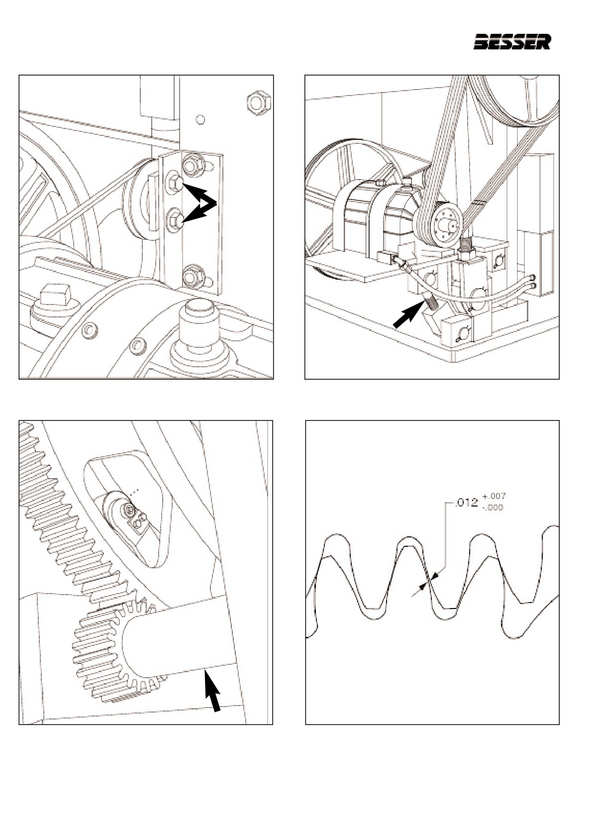
Figure 11.4
INPUT PULLEY BELT TENSION
Figure 11.5
OUTPUT PULLEY BELT TENSION
Figure 11.6
PINION SHAFT
Figure 11.7
GEAR TOOTH GAP
11-6
466361F9710US F1 29OC99
SECTION 11
MAINTENANCE
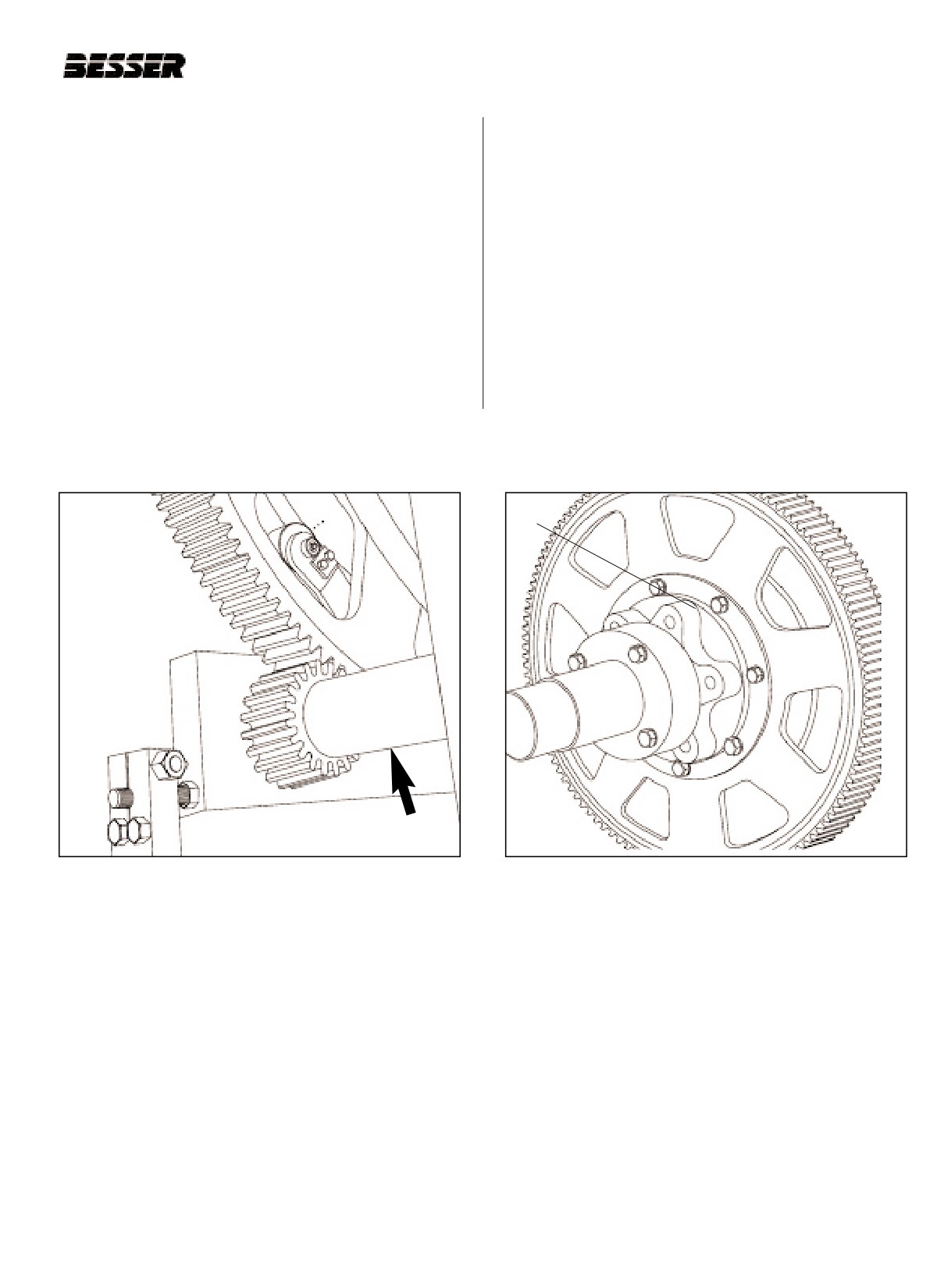
11.2.3 REPLACING PINION SHAFT
11.2.4 TURNING BULL GEAR.
Before replacing pinion shaft, make sure machine is in
The bull gear must be turned in order to extend its life
safe position. Stripper head frame and pallet receiver
span. Turn bull bear when .020” (.5mm) clearance
frame must be down. Also, make sure there is no ten-
develops between pinion and bull gear teeth.
sion on the pinion gear.
Before turning bull gear, make sure machine is in its
1. Remove pinion shaft assembly from machine and
safe position. Stripper head frame and pallet receiver
transfer parts to be rebuilt to new shaft.
frame must be down.
2. Reinstall rebuilt assembly and adjust so teeth have
1. Unbolt bull gear from hub (bolt A in figure 11.9).
equal pressure across width and a clearance of
.012” to .019” (.3mm to .5mm).
2. and turn pinion shaft to turn bull gear 900.
3. Finally, rebolt to hub.
A
Figure 11.8
PINION SHAFT
Figure 11.9
BULL GEAR
11-7
466361F9710US F1 29OC99

SECTION 11
MAINTENANCE
11.2.5 PINION SHAFT (FIGURE 11.6 AND 11.7)
COMPONENT
CHECK FOR
ACTION
HOURS
Sheave P/N 112339F6280
Wear - Match with gauge #112541
replace
400
Bearings
.005” [.127mm] radial move
replace
2000
0.012” to 0.019”
Pinion
Alignment, wear and clearance
between teeth
Taper lock-tight
Lubrication
Automatic
-
-
Table 11.4
11.2.6 CAM SHAFT (NOT ILLUSTRATED)
COMPONENT
CHECK FOR
ACTION
HOURS
Bull gear
Alignment, wear and tightness
adjust
installation
Bearings
Clearance, seals
repair / replace
2000
Lubrication
Automatic
-
-
Cam assemblies
Table 11.5
11.2.7 FEED, STRIPPER HEAD AND PALLET RECEIVER SHAFTS & LINKS
COMPONENT
CHECK FOR
ACTION
HOURS
Bearings
Wear. .030” [.76mm] clearance
replace
1000
Rollers
Wear. .010” [.25mm] clearance
replace
1000
Wear. .030” [.76mm] between feeler gauge
Bushings
replace
1000
pin and bushing
Pins
Wear. .010” [.25mm]
replace
1000
Links
Link ends tightness (see torque chart)
replace
400
Link bearings
Wear. .030” [.76mm] clearance
replace
1000
Link pins
Wear. .010” [.25mm] clearance
replace
1000
Table 11.6
11-8
466361F9710US F1 29OC99
SECTION 11
MAINTENANCE
11.2.8
FEEDBOX
COMPONENT
CHECK FOR
ACTION
HOURS
Agitator motor
Lubrication (see manufac.’s manual)
lubricate
4000
Agitator sheave
Worn (match with gauge #112541)
repair / replace
400
Agitator belts
Wear and tension (match with gauge #112541)
check level
400
Agitator bearings
Wear
replace
400
Agitator nylons
Worn. .030” [.76mm] clearance
replace
400
Agitator rollers
Worn. .010” [.25mm] clearance
replace
400
Agitator bars
Worn more than 1/2” [13mm] in dia.
replace
400
Back bar and guide
Bent or worn more than .030” [.76mm]
clean & replace
Daily
Liners
Bent or worn more than .060” [1.5mm]
replace
Daily
Loose back bar
Bent or worn more than .100” [2.5mm]
replace
Daily
Hopper
Bent or worn more than .100” [2.5mm]
replace
Daily
Gate
Bent or worn more than .100” [2.5mm]
replace
Daily
Baffle
Bent or worn more than .100” [2.5mm]
replace
Daily
Apron plate
Worn more than .125” [3mm]
replace
Daily
Wear shoes
Worn more than .125” [3mm]
replace
Daily
Rollers
Worn more than .010” [.25mm]
replace
100
Bushings
Worn more than .030” [.76mm]
replace
100
Pins
Worn more than .010” [.25mm]
replace
100
Back top plate
Worn more than .100” [2.5mm]
replace
100
Feedbox track
Worn more than .060” [1.5mm]
replace
400
Table 11.7
11.2.9 PALLET & BLOCK DELIVERY
COMPONENT
CHECK FOR
ACTION
HOURS
Pallet conveyor chain
3% elongation and sloppy rollers
Adjust
1000
Pallet conveyor shafts
-
-
-
Pallet conveyor bearings
.020” [0.5mm] radial movement
replace
1000
Pallet conveyor sprockets
No longer smooth when engages chain
replace
1000
Pallet conveyor trunion shaft bearings
.020” [0.5mm] radial movement
replace
1000
Pallet conveyor chain track
1/8” [3mm] wear or can no longer adjust
replace
1000
Pallet lugs
Won’t consistently push pallets
replace
1000
Table 11.8
11-9
466361F9710US F1 29OC99
SECTION 11
MAINTENANCE
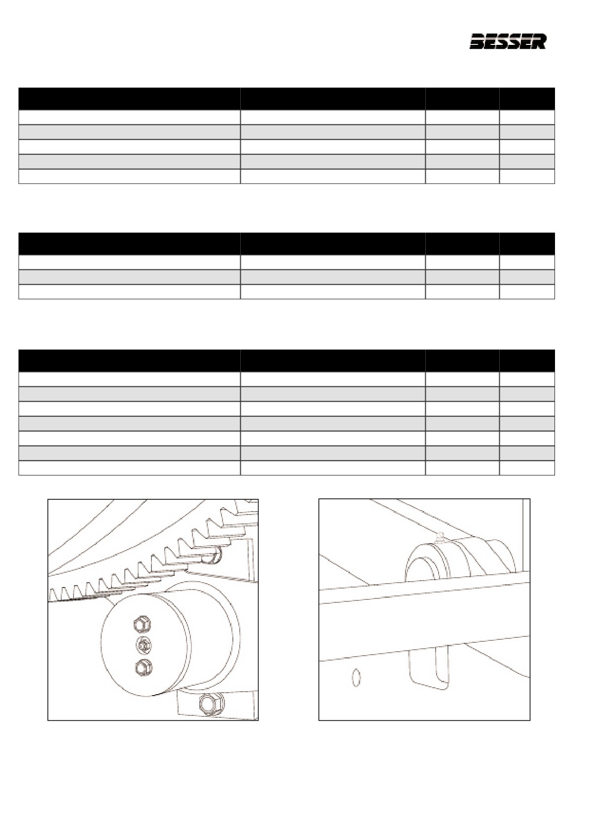
11.2.10 PALLET & BLOCK MOVING BARS
COMPONENT
CHECK FOR
ACTION
HOURS
Linkage bearings
.010” [0.25mm] radial movement
replace
1000
Slides
Can no longer adjust
replace
1000
Guide rollers
won’t turn or .010” [0.25mm] radial movement
replace
1000
Pallet cradle
Bent or broken
replace
1000
Block fingers
Worn more than 1/16” [1.6mm]
replace
1000
Table 11.9
11.2.11 PALLET & BLOCK SUPPORT SHAFT
COMPONENT
CHECK FOR
ACTION
HOURS
Linkage bearings
.030” [0.76mm] radial movement
replace
1000
Bearings
.030” [0.76mm] radial movement
replace
1000
Cam rollers
won’t turn or .005” [0.13mm] radial movement
replace
1000
Table 11.10
11.2.12 PALLET & BLOCK DRIVE
COMPONENT
CHECK FOR
ACTION
HOURS
Shaft bearings
005” [0.13mm] radial movement
replace
1000
Link bearings
005” [0.13mm] radial movement
replace
1000
Cam
Surface rough or penned
replace
1000
Gearbox
(see manufac.’s manual)
replace
1000
Drive belt and sheaves
(see manufac.’s manual)
replace
1000
Motor
(see manufac.’s manual)
replace
4000
Motor brake
(see manufac.’s manual)
replace
1000
Table 11.11
Figure 11.10
Figure 11.11
11-10
466361F9710US F1 29OC99
SECTION 11
MAINTENANCE
11.2.13 TOOLS
TOOL
PART #
Belt & sheave gauge
#112541
Posydine stock gauge (inside unit)
Belt tension gauge
#106666
Bearing feeler gauge - .015” [0.38mm]
#94133
Pry bar (Goose neck) (Mold centering)
#61397
Multiple lockout device
#111140
Padlock
#111139
11.2.14 BOLT TORQUE CHART
THREADED
S.A.E. GRADE
S.A.E. GRADE
DIAMETER
2
5
1/4”
60 - 80 LB-IN.
100 - 120 LB-IN.
3/8”
20 - 30 LB-FT.
30 - 40 LB-FT.
1/2”
40 - 60 LB-FT.
65 -85 LB-FT.
5/8”
90 - 110 LB-FT.
140 - 160 LB-FT.
3/4”
145 165 LB-FT.
250 - 270 LB-FT.
7/8”
165 - 185 LB-FT.
420 - 440 LB-FT.
1”
230 - 250 LB-FT.
640 - 660 LB-FT.
1 1/4”
500 - 520 LB-FT.
1200 -1250 LB-FT.
1 1/2”
600 - 620 LB-FT.
1400-1500 LB-FT.
11-11
466361F9710US F1 29OC99
SECTION 11
MAINTENANCE
11.3
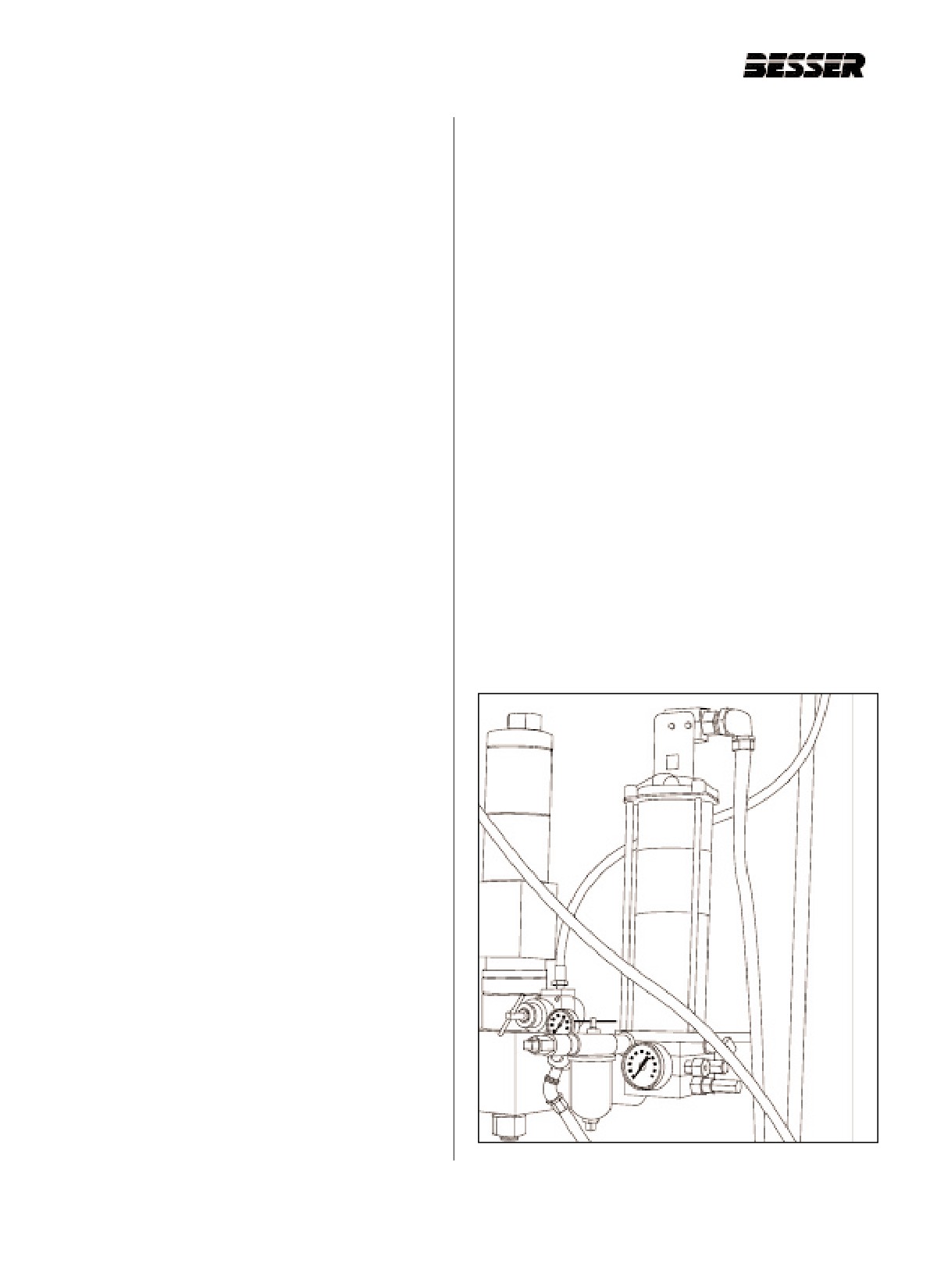
TRABON PUMP MAINTENANCE
11.3.2 TRABON PISTON STROKE ADJUSTMENT
The adjustments covered in this section are:
AL-5M Pump stroke adjustment for Besser block
machines:
1. PUMP IN-FEED PRESSURE.
On AL-5M pumps, we recommended in the past a set-
2. THE SOLENOID FLOW ADJUSTMENT controls the
ting of .020 which would be 20 thousandths cubic inch-
speed the air piston shifts.
es of grease per stroke or.328 cubic centimeters. .020
is the middle of 3 calibration marks.
3. THE PUMP PISTON STROKE determines how
much grease is pumped each stroke.
On the right side of the pump, remove the calibrated sil-
ver cap. Put the open end of the cap up against the lock-
4. LUBRICATION RATE ADJUSTMENT Adjusted
nut. The stroke is how far the screw sticks out and match-
through the Graphic Control Station. Refer to section
es the calibrations on the cap. To adjust the stroke,
9.5: “TIMER ADJUSTMENT” - F3 -Timers 5 and 6.
loosen the lock nut on the adjustment screw. Turn the
screw inward or clockwise to reduce the stroke. Turn the
5. FILLING THE GREASE PUMP.
screw outward or counterclockwise to increase the
stroke. The lock nut has to be retightened and the cap
For more complete instructions on the TRABON
placed up against it again to recheck the settings after
PUMP, refer to “Trabon Pump Owner’s Service Manual
you change them. After final adjustment, tighten lock
#437629F913”.
nut, then tighten silver cap onto the adjustment screw.
Warning: Be very careful while adjusting or trou-
L-25M Pump stroke adjustment:
bleshooting the lube system that the machine is not
On AL-25M pumps used on block machines, set the
turning, and the main drive motor is off.
pump stroke on the mark between the 30 line and the
.075 line. This will be a setting of approximately.052
cubic inches which is equal to .853 cubic centimeters.
11.3.1 TRABON IN-FEED PRESSURE
The method of adjustment is described and shown in
the Pump owner’s manual on page 4-2 and 4-3.
ADJUSTMENT
The Trabon pneumatic pump has a air-to-lube ratio of
30 to 1. The Trabon in-feed air pressure on many
Besser Vibrapacs is supplied from the Bescodyne main
drive brake air regulator. In this case when the brake
regulator adjustment is changed, it also affects the
Trabon pump. The Trabon pump pressure ideally
should be 60-80 psi [4.1-5.5 bar], which can develop at
least 1800 psi [124 bar] pumping pressure.
Note: It may be advantageous to connect your Trabon
pump to the Bescodyne main drive clutch rather
than to the brake. The clutch air pressure adjust-
ment is higher than the brake. Starting in 1991,
Besser block machines have a separate air regu-
lator supplied to the Trabon pumps. The plastic
air solenoids on double acting pumps may not
operate with less than 70 PSI [4.8 bar].
Figure 11.12THE TRABON LUBE PUMP
11-12
466361F9710US F1 29OC99
SECTION 11
MAINTENANCE
AL-25M Pump stroke adjustment for Besser slump
11.3.5 FILLING THE GREASE PUMP
mixers:
Set the stroke adjustment for .030 cubic inches, .492
Grease To Use:
cubic centimeters for AL-5M and AL-25M pumps.
We recommend Lithium based E.P.-1 grease, such as
Shell Alvania E.P. No. 1, or Mobilux E.P. No. 1. In cold-
er climates and/or in colder months, Shell Alvania E.P.
11.3.3 TRABON SOLENOID FLOW CONTROL
No. 0, Mobilux E.P. No. 0, or grease with equivalent
ADJUSTMENT FOR ALS PUMPS
specifications may be used.
The solenoid flow adjustment controls the speed at
Filling the Pump:
which the Trabon air piston shifts. The solenoid flow
The Trabon Pump, on the average, should be filled with
controls should be adjusted to get a gentle but positive
grease after 35 hours of operation. It is best if the pump
shift of the piston without slamming.
never runs out of grease because excessive air can be
introduced into the system. Before filling the pump, turn
Single acting ALS pumps have one flow adjustment
the filter handle a few times to clean it. Attach a filling
which controls the in-feed air into the SA port.
pump hose to the fill stud quick disconnect located just
Depending on the air plumbing, you may have to use
ahead of the filter.
an offset screwdriver to adjust the flow control.
Warning: If a high pressure supply pump is used to fill
Turn the solenoid adjusting screw clockwise all the way
the Trabon grease reservoirs, wear safety glasses.
in. Back the adjusting screw out 1/16 to 1/4 turn. Press
Pressure could build up high enough to fracture the
the manual shifting override button on the air solenoid.
reservoir and send particles flying.
You should be able to hear the air piston shifting and
Note: If air does get into the automatic greasing sys-
the exhaust air exiting the DA port. Adjust the solenoid
tem, refer to the proper sections:
as slow as possible while still getting a positive shift of
the piston. If you place your hand on the air cylinder of
1. To bleed air from the Reservoir, refer to Section 1 in
the Trabon pump, you should also be able to feel it
Pump owner’s manual.
shifting.
2. To bleed air from the Pump, refer to Section 6 in
Pump owner’s manual,
3. To bleed air from the Feeder Blocks and Grease
11.3.4 TRABON SOLENOID FLOW CONTROL
Lines, refer to Section 9 in Pump owner’s manual.
ADJUSTMENT FOR ALJ PUMPS
Operate the filler pump at a steady speed to allow air-
free filling of the reservoir. Filling the pump too fast may
On the double-acting pumps when the solenoid flow
form air pockets. Also to avoid inducing air into the
controls are adjusted, the exhaust air flow is also
pump, make sure there is enough grease in the supply
adjusted. When the Trabon air piston shifts forward, air
source to fill the reservoir without disconnecting and
flows in the SA port and out the DA port. So, to adjust
reconnecting the filler hose. While filling the pump,
the speed of the piston shift forward, turn the front or
watch the grease level rise. Stop adding grease when
right hand flow control which adjusts the air coming out
the level reaches the air bleed hole.
of the DA port. Loosen the lock nuts and turn both
screws all the way clockwise to shut off the flow. Start
Note: Never fill over the air bleed hole; this will cause a
by backing both screws out 1/2 turn and testing the
vapor lock in the system. The air bleed hole is
pump shift with the plastic manual override button. The
found about 2/3, the way up the plastic reservoir
reverse speed is controlled by air for the most part, but
on the right. When filling is complete, turn the
the return spring will also be helping. The reverse
supply source off and disconnect supply line
speed is controlled by the exhaust air coming out of the
from the fill stud. Install the plastic dust cap over
SA port which is the back or left hand flow control. Set
the fill stud to keep dirt out of the lube system.
both flow control adjustments to obtain a positive shift
without a hard, slamming action. When adjustments
are completed, tighten the lock nuts so the adjustment
screws cannot move out of adjustment.
11-13
466361F9710US F1 29OC99
SECTION 11
MAINTENANCE
11.4
BEARING MAINTENANCE
11.4.1 REMEMBER THESE DO’S AND DON’TS
When handling bearings:
DO:
DON’T:
1.
Remove all outside dirt from housing before expos-
1 . Don’t work in dirty surroundings.
ing bearing.
2. Don’t use dirty, brittle or chipped tools
2.
Treat a used bearing as carefully as you would a
new one.
3. Don’t use wooden pallets or work on wooden
bench tops.
3.
Work with clean tools in clean surroundings.
4. Don’t handle with dirty, moist hands.
4.
Handle with clean, dry hands, or preferably with
clean canvas gloves.
5. Don’t use gasoline containing tetraethyl lead, as
they may be injurious to health.
5.
Use clean solvents and flushing oils.
6. Don’t spin unclean bearings.
6.
Lay bearings out on clean paper.
7. Don’t spin bearings with compressed air.
7.
Protect disassembled bearings from rust and dirt.
8. Don’t use cotton waste or dirty cloths to wipe bear-
8.
Use clean lint-free cloths or rags to wipe bearings.
ings.
9.
Keep bearings wrapped in oil proof paper when not
9. Don’t expose bearings to rust or dirt.
in use.
10. Don’t nick or scratch bearing surface faces.
10. Clean inside of housing before replacing bearing.
11-14
466361F9710US F1 29OC99
SECTION 11
MAINTENANCE
11.4.2 LUBRICATION TIPS
Lubrication is essential for the proper operation of bear-
bearing user, metal chips, grit, abrasive, dust, etc., are
ings. Grease and oil are both used over a considerable
all DIRT. Avoid them.
range of speeds and operating temperatures. The
choice of the type of lubricant should be made only
after careful consideration of the several factors
11.4.4 PREVENTIVE MAINTENANCE
involved.
Have a perfectly clean work bench on which to place
1.
Keep lubricants clean. Dirt causes most bearing fail-
bearings before and after cleaning. Place the bearing in
ures, and one easy way for it to get to bearings is to
a degreaser or in a container of appropriate solvent
be put there in the grease. Keep covers tight on all
such as standard solvent, kerosene, methyl-chloroform,
grease cans. Use only clean dishes and clean spat-
or similar solvents. “Swirl” the bearing around in the
ulas with grease. Keep grease stored away from all
cleaning solvent allowing it to wash through the bear-
dust, dirt, and metal chips,
ing, carrying away any grit particles and dissolving all
oil or grease. Finally, slowly revolve the inner ring so
2.
Standardize your greasing procedures. Make sure
the cleaning solvent reaches all parts of the bearing.
all maintenance personnel understand proper greas-
Do not allow the bearing to rest on the bottom of the
ing methods. Do not let inexperienced personnel
container. Cleaning of a bearing interior around the
take over greasing; it is too important. Establish pre-
balls or rollers is often done with a normal paint brush.
cise instructions regarding cleaning of greasing
This is a satisfactory practice although care should be
equipment, grease fittings, grease cups (before refill-
taken to use a good quality brush which does not lose
ing them). Oil cups and grease fittings can be
its bristles, and that none of the bristles become lodged
marked with colored paints to systemize your relubri-
between the balls or rollers and separators or rings. A
cation.
piece of bristle can be as harmful as a steel chip.
3.
Relubricate on schedule. Do not wait for trouble to
ONCE IN, DIRT IS HARD TO GET OUT - A clean bear-
signal the need for additional lubrication.
ing placed on a dusty bench always becomes contami-
Relubrication schedules should be posted on
nated. Dirt, once entrenched in the separator, is
machines.
exceedingly difficult to remove. Make cleanliness your
first rule for working with bearings,
4.
Use only high grade grease in bearings. Low grade
grease is a false economy. Its use usually results in
Bearings with closures on both sides should not be
shortened bearing life. Also, try to use the grease
cleaned by dipping, spraying and the like, which would
recommended by the machine manufacturer.
wash out the grease. The outer surfaces of such bear-
ings may be carefully wiped with a lint-free cloth and
5.
Over-greasing is bad, It causes churning of the lubri-
light oil or solvent, after which they can be lightly coat-
cant and subsequent over-heating. If bearing runs
ed with a protective lubricant, and wrapped to protect
hot after relubrication, open the drain plug and let
against dirt and corrosion.
some of the grease run out while the bearing is
operating. Never fill end-bells more than one third
Throughout the cleaning process, and especially where
full when re-greasing.
a bearing has been solvent cleaned, remember that
corrosion can be caused by perspiration from hands.
6.
Never start a new machine until the bearings have
been lubricated according to directions.
So if a bearing has been solvent cleaned, wipe it care-
fully before applying a protective oil coat.
11.4.3 WATCH OUT FOR DIRT
USE AIR WITH CAUTION - Never use unfiltered air.
Make sure all traces of water and dirt in the air line are
The most important precaution to be observed in han-
trapped out. Dirty air can blow dust into the bearing
dling or using bearings is to keep them clean. Dirt is the
ruining careful cleaning work. Never allow the air blast
greatest enemy of bearings. It causes wear, destroys
to spin a bearing. If you must use air, hold bearing and
their accuracy, and shortens their life. To the
hose carefully.
11-15
466361F9710US F1 29OC99
SECTION 11
MAINTENANCE
11.4.5 RELUBRICATE AFTER CLEANING
Always re-lubricate bearings immediately after they
failure, it should be removed with care to avoid damage
have been cleaned. Immerse in light clean oil and
to the shaft, housing or other machine parts and to
rotate the inner ring very slowly until all the solvent has
avoid obliterating the cause of failure.
been removed. Oil has a tendency to slip away from
metal surfaces already wet with solvents, leaving the
As mentioned before, at least one of the bearing rings
bearing surfaces unprotected and in danger of rust and
is press fitted sometimes to a very tight fit. At this point,
corrosion.
we are concerned largely with the proper handling of
press fitted parts.
11.4.6 REWRAP AFTER CLEANING
The first basic principle is that no press fit should be
broken unless it is essential to the job being done,
Immediately after re-lubricating the bearing, wrap well
Many roller bearings are separable and when it is cer-
in clean polyethylene or oiled paper. Replace in its box,
tain the bearing itself has not been damaged, it is best
making sure that inside of box is also clean. Reseal the
to leave the press fitted member in place. In addition to
box. A good shop practice is to write on the sealing
the time and trouble involved, removal may cause dam-
tape the date of cleaning, the type of lubricant, and the
age to the bearing seat. However, if any failure is evi-
name of the person cleaning the bearing.
dent, the entire bearing should be replaced. The sec-
ond basic principle is that, in removing a ring, the dri-
ving force be directed through the inner or outer ring
11.4.7 BEARING REMOVAL
which is being removed, and not be transmitted through
the balls, rollers, separators, closures and the like.
Bearings may have to be removed as part of an over-
haul program to service another part, or to replace the
bearing. In any case, even if the bearing is an obvious
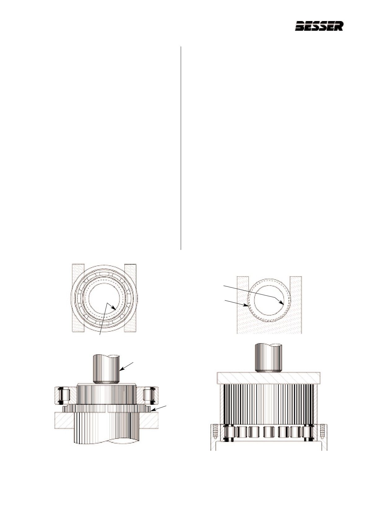
Shaft Shoulder
Bearing Inner Ring
Shaft Shoulder
Press Ram
Split ring
Figure 11.13Bearings
11-16
466361F9710US F1 29OC99
SECTION 11
MAINTENANCE
The familiar arbor press is a very good machine for
to build a simple puller adapted to the job, especially if
removing (or installing) bearings. if action is rapid,
it is repetitive.
smooth and positive. In addition, it can supply a
greater force than most other means. Further, it is a
The use of a hammer and drift directly in the ring is
useful shop accessory for many other types of work.
very bad practice. An auxiliary fixture as shown here
Unfortunately, space restrictions prevent its use in
should be used.
many jobs.
Large roller bearing inner rings are particularly difficult
The arbor press requires various fixtures as an aid to
to remove by any of the methods given here. Usually,
removing or installing bearings. Although some of these
these rings are separable and it is necessary to destroy
aids are not inexpensive to make, their use is justified
them by heating or splitting. No specific instructions can
by the saving in time and by the freedom from damage
be given here except that ail attempts should be made
to the equipment under repair. This is especially true if
to prevent damage to the shaft.
the job is a repetitive one.
The best fixture for pressing off inner rings from a shaft
11.4.8 IDENTIFICATION DAMAGE AND FAIL-
is a split ring with the outer area relieved. For most
URE ON BEARINGS
roller bearings, flat bars or U-shaped washers as
shown here are quite satisfactory. They are not recom-
INSPECTION:
mended for ball bearings since the outer ring or the clo-
When a machine or other piece of equipment is down
sure may project beyond the inner ring face a small
for repair, the objective of the maintenance personnel is
amount, A possible solution to this problem is to insert
to repair it and get it going as soon as possible.
a small piece of shim stock about 0.01“ [0.25mm] thick
However, some knowledge of bearing failure and dam-
between the fixture and the inner ring face. Also, an
age identification is required to determine:
interference condition can be checked by oscillating the
outer ring while applying a little pressure.
1.
Whether the bearing is suitable for further service.
The arbor press can also be used to remove outer rings
2.
If there is some underlying cause for failure so that
from housings in those cases where the housing can
corrective measures can be applied before
be handled in the arbor press and where a portion of
installing a new bearing. Here are some inspection
the outer ring is exposed. In the event the entire outer
tips and techniques to be used before or during
ring is exposed, a section of tubing capped by a flat bar
machine dismantling Before removing or replacing
can be used as illustrated. In other cases, where there
a “noisy” bearing, try to determine if the bearing is
is axial space restriction, a fiat bar can sometimes be
the cause. To start with, a common complaint is
inserted to bear against the face.
that the bearing is “noisy”. This is a natural reaction
of machine users to unusual noise emanating from
Next to the arbor press, the puller is the best removal
a machine. Generally, a noisy bearing produces a
tool and is often necessary because of size and space
continuous whine. A pulsating noise is usually the
restrictions in the arbor press. Pullers are made in dif-
result of a malfunction of some other part. It must
ferent configurations and sizes and with accessories to
be remembered too that all ball and roller bearings
make them adaptable to various jobs. Larger sizes are
have some noise level. Bearings in good condition
available with a hydraulic piston and hand pump.
tend to produce a pleasant sound compared to a
harsh sound from one that is not functioning prop-
As with the arbor press, the pressure must be applied
erly. Another point to remember is that a noisy
directly through the press fitted member. In addition,
machine is not always a sign of imminent bearing
where screw adjustments to the arms are made, care
failure, but may indicate the need for lubrication.
should be taken to pull the press fitted part off straight
and true. It is advisable to use a piece of soft metal in
On dismantling a machine, it is often possible to
the shaft center to prevent scoring due to the pressure
make pertinent examination of the bearing without
of the puller screws.
removing it from the shaft or housing
The least desirable method is removal of inner and
outer rings by driving with a hammer. Where machine
shop facilities are available, it may be worth the effort
11-17
466361F9710US F1 29OC99
SECTION 11
MAINTENANCE
This is especially true with separable roller bearings,
If a part adjacent to the bearing has failed, it is good
including single row tapered bearings. In such cases,
practice to replace the bearing even though it is not
major damage or failure can readily be noted. Ball
obviously damaged. It is also good practice to replace a
bearings, being non separable, present considerably
bearing which has seen considerable service. The
more difficulty, especially those with seats or shields.
good judgment of the maintenance person is required
here to determine a balance between the cost and diffi-
In all cases, if failure or damage is not obvious, look for
culty of replacement vs. the possibility of a subsequent
these signs :
breakdown.
1.
A loose fit of the rotating ring. This is probably a sig-
nal that the ring has rotated and that wear has taken
11.4.9 TYPES OF BEARING DAMAGE
place. Where the ring is not loose by normal feel but
there are rust-like loose particles around the fit area,
Here are photographs and a description of the more
check carefully for wear.
common types of bearing damage. Many of these type
of damage, especially in ball bearings, cannot readily
2.
Indents, flaking or heavy rust on the operating sur-
be seen without dismantling the bearing. Hence, this
faces. In many cases, these conditions result from
identification is of benefit in cases of chronic failure,
metal particles thrown off by failure of an adjacent
where a specific cause is sought. These types of failure
gear, or the like.
are grouped as those caused by:
3.
Undue looseness in a radial bearing. In most cases,
- Installation
radial shake, which can be felt by hand, is an indica-
- Operating conditions
tion that undue wear has taken place. Another sign
- Normal fatigue
of wear is a gritty feel of the lubricant adjacent to the
bearing. In connection with the noise problem dis-
cussed earlier, keep in mind that excessive bearing
11.4.10 INSTALLATION DAMAGE
wear can be a cause of noise by allowing the rotat-
ing member to move due to unbalance or other
BALL RING BRINELL:This type of brinelling on the
forces.
shoulders is caused by excessive thrust which pushes
the balls up on the pathway and creates a triangular
4.
Missing balls or rollers. If one or more balls or rollers
shaped dent or “Brinell” spot at the junction of pathway
fall out of a separator, sufficient wear to the separa-
and shoulder.
tor may have occurred to indicate the need for bear-
ing replacement.
5.
Rough rotation or “sticking” of the bearing when
rotated by hand. This test requires considerable
judgment and experience. In the case of “open”
bearings, the bearing should be cleaned and lightly
oiled before testing. A good practice is to clean it
again using a strong solvent like varnish remover,
then oil and retest. If the roughness or sticking per-
sists, discard the bearing. Ball bearings with clo-
sures cannot, of course, be washed and oiled.
These can be given the hand rotation test, repeated-
ly rotating and oscillating while applying a little axial
pressure in one direction and then the other.
We do not recommend rotating bearings by power to
check the noise characteristics. Besides the obvious
danger of damage, this test requires great experience
to determine if the bearing is faulty. As pointed out
before, all bearings have some sound level,
11-18
466361F9710US F1 29OC99
SECTION 11
MAINTENANCE
11.5
SMARTPAC MAINTENANCE AND
CARE
1.
Store in clean dry area.
2.
Lubricate bearings before storing.
3.
Keep quick disconnects clean and capped.
4.
For extended storage, spray rust preventive in tube
hole & seals.
5.
Handle units with care; do not hit or pry the
weights.
6.
Mount to good mold side bars and make sure bear-
ing housings are seated directly to bar and vibrator
bolts are properly torqued. DO NOT force by hitting
the bearing housing with a hammer.
7.
Lift unit by the shaft, not by bearing housing as this
can damage the seals.
8.
Clean quick disconnects before engaging.
9.
Replace “O” ring in quick disconnects at least every
month or when they become worn or damaged.
10.
Never operate system pressure above 80 psi (5.5 bar).
11. Use only new clean fluid when filling the system.
Contamination will cause erratic operation.
12- Do not disassemble unit.
13. To prevent crimping of shaft, Besser recommends
the sheaves be tightened to 18 lbs ft. (27 N.M.) of
torque. Tightening over 18 lbs ft.(27 N.M.) will
cause rotary union to bind, reducing its life.
14. Never put undue pressure on rotary union fittings or
connection hose.
15. Lubricate vibrator bearing every 8 hours with 1 oz
[30 ml]. of clean high temperature synthetic grease
#114135.
16. Always have guards in place when operating vibra-
tor motors.
17. Keep system in top condition by replacing any worn
belts, sheaves, etc...
11-19
466361F9710US F1 29OC99
SECTION 11
MAINTENANCE
11.6 SLC CONTROLLER MAINTENANCE
11.6.1 PREVENTIVE MAINTENANCE
The SLC controller will give you reliable service. If a
problem should occur, the first step in the troubleshoot-
The printed circuit boards of the controller must be pro-
ing procedure is to identify the problem and its source.
tected from dirt, oil, moisture and other airborne conta-
Do this by observing your machine or process and by
minants. In order to protect these boards, the controller
monitoring the diagnostic LED indicators on the CPU,
must be installed in an enclosure suited to the environ-
Power Supply and I/O modules. By doing this, the
ment. The interior of the enclosure should be kept
source of a problem can generally be narrowed down
clean and the enclosure door should be kept closed
to the processor, wiring, or the input/output devices.
whenever possible.
To assist you in identifying the source of the controller’s
Regularly inspect your terminal connections for tight-
operation problem, we have included some trou-
ness. Loose connections may cause improper function-
bleshooting considerations including status indication,
ing of the controller or damage the components of the
trouble description, probable causes and recommend-
system.
ed action.
CAUTION: To ensure personal safety
and to guard against damaging equip-
11.6.3 DIAGNOSTIC CHECKS
ment, inspect connections with incom-
ing power OFF.
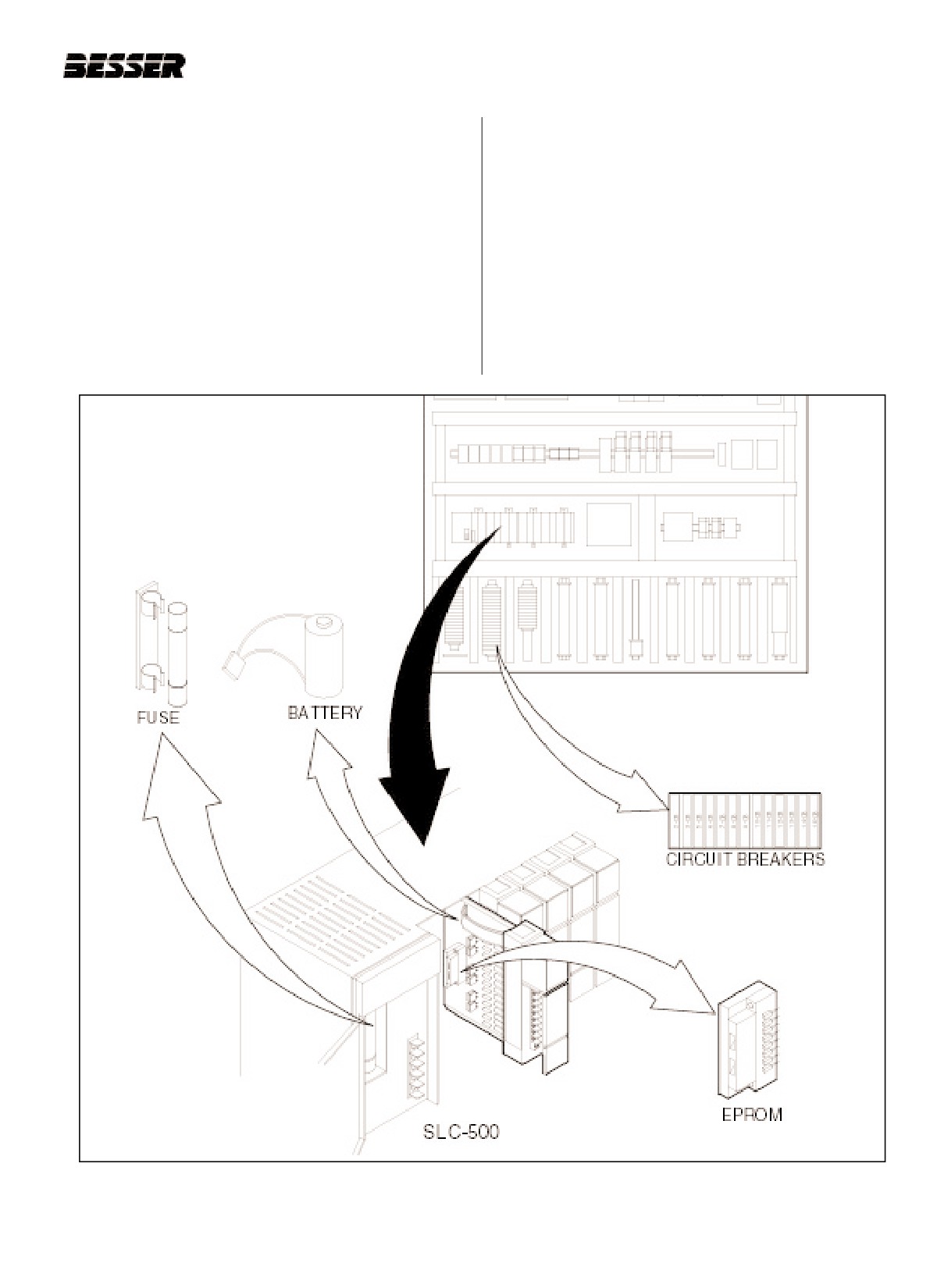
A.Battery
The SLC Controller has power supplied by a
The National Fire Protection Association (NFPA)
lithium battery. The battery is located in the
gives recommendations for electrical equipment
power supply inside the control panel. Replace
maintenance. Refer to article 70B of the NFPA for
the battery if the low battery signal activates.
general requirements regarding safety related work
See figure 11.14 (page 11-22).
practices.
B.Fuses
A burned-out fuse may cause the power supply
11.6.2 TROUBLESHOOTING
indicator light to illuminate in controller. Check
When troubleshooting, pay careful attention to these
the two fuses, located behind the lithium bat-
general warnings:
tery. The battery is located in the SLC-500 con-
trol panel. Replace burned-out fuses with new
CAUTION: Have all personnel remain
fuses. See figure 11.14 (page 11-22).
clear of the controller and equipment
when power is applied. The problem
C.Circuit breakers
may be intermittent and sudden.
A tripped circuit breaker may result for no
apparent reason. Check the circuit breakers,
Unexpected machine motion could result in injury.
located in the SLC control panel, and reset any
Have someone ready to operate an Emergency Stop
tripped circuit breakers. See figure 11.14 (page
switch in case it becomes necessary to shut off
11-22).
power to the controller equipment. Also, see NFPA
70E Part II for additional guidelines for safety related
D. Memory loss
work practices.
When the power to the panel goes off due to a
power surge, drop or a dead battery, a memory
Never reach into a machine to actuate a switch since
loss may result. The CPU fault light will illumi-
unexpected machine motion can occur and cause
nate to indicate problem. To restore the memo-
injury. Use a wooden stick. A metal rod could dam-
ry, turn the panel power OFF. Insert EPROM
age the machine and/or conduct current to the per-
into the inside of the processor. Restore the
son holding it.
power. The SLC-500 will automatically read the
EPROM into its RAM and go into RUN mode.
Remove all electrical power at the main power dis-
The CPU light will illuminate to indicate a suc-
connect switches before checking electrical connec-
cessful transfer. Turn the power OFF. Remove
tions or inputs/outputs causing machine motion.
the EPROM from the unit.
11-20
466361F9710US F1 29OC99
SECTION 11
MAINTENANCE
11.6.4 USING THE TROUBLESHOOTING
3. Once the LED status indicators are matched to the
CONSIDERATIONS TABLE GUIDE
appropriate table, simply move across the table
identifying trouble Description and Probable Causes.
To receive the maximum benefit of this Table Guide,
4. Then follow the Recommended Action steps for
we recommend the following steps in using its informa-
each probable cause until the cause is identified.
tion:
5. If Recommended Actions do not identify the cause
1. Identify your Power Supply and CPU LED status
of trouble, contact your local Allen-Bradley Sales
indicators.
Office.
2. Match your controller’s status LED indicators with
the status LED indicators located in the first column
in the Troubleshooting Considerations Table.
Figure 11.14 SLC CONTROLLER BATTERY, FUSES, EPROM AND CIRCUIT BREAKERS.
466361F9710US F1 29OC99
11-21
SECTION 11
MAINTENANCE
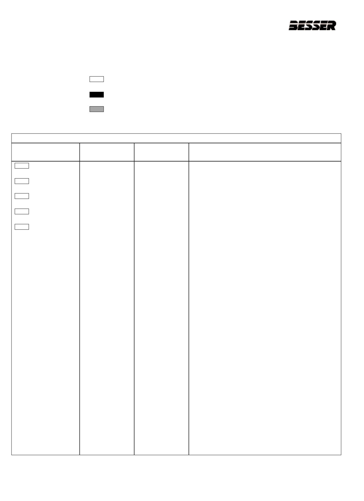
11.6.4 TROUBLESHOOTING TABLE GUIDE
Refer to the following log to determine the status of the LED indicators:
Indicates that LED is OFF
Indicates that LED is ILLUMINATED
Indicates that LED is FLASHING
TROUBLESHOOTING CONSIDERATION
STATUS
DESCRIPTION
PROBABLE
RECOMMENDED
INDICATORS
CAUSES
ACTION
POWER1
Inadequate
No line power
1.
Verify proper line voltage and connections on the
System Power
power supply.
PC RUN
2.
Verify proper 115/230 Volt power supply jumper
CPU FAULT
placement.
FORCED I/O
Refer to Page 5-6 of the SLC manual for
placing the jumper.
BATTERY LOW
Power supply fuse
1.
Check for proper power supply connections.
Replace fuse.
1
On modular SLC con-
figuration systems,
2.
If fuse blows again, replace power supply.
you will find the
POWER LED indica-
Refer to page 8-7 of the SLC manual for fuse
tor on the rack mount-
location and replacement procedures.
ed power supply of
each rack.
Power supply
1.
Remove line power to power supply. Remove
overloaded
several output modules from the chassis. Wait
five minutes. Reapply power.
2.
If condition reoccurs, re-calculate module config-
uration power required and verify proper power
supply selection. See page 1-7 of the SLC
manual.
Note: This problem can occur intermittently if power
supply is slightly overloaded when output
loading and temperature varies.
Defective power
1. Recheck other probable causes.
supply
2. Monitor line power to chassis power supply for
possible transient or shorting.
3. Replace power supply
11-22
466361F9710US F1 29OC99
SECTION 11
MAINTENANCE
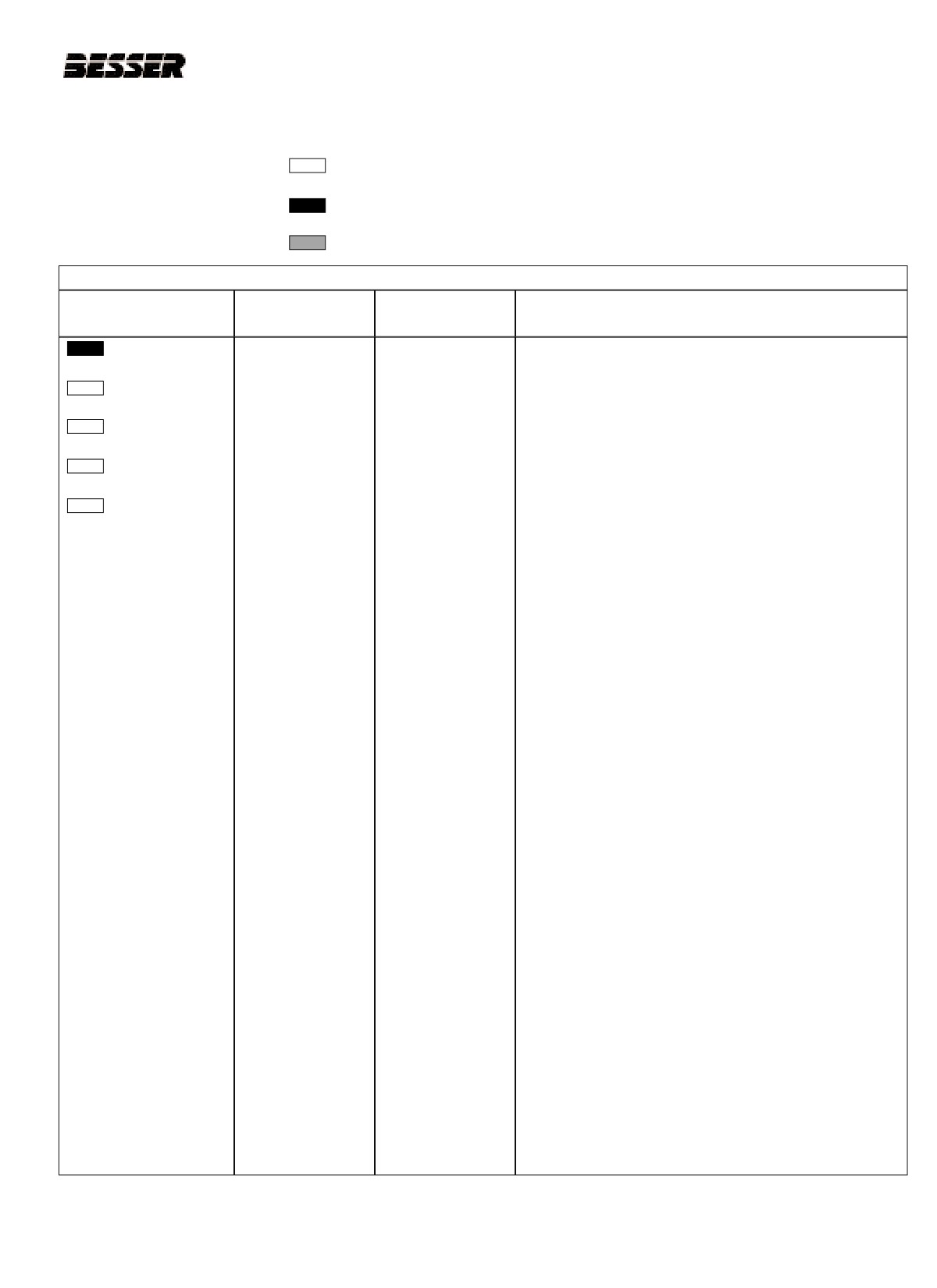
Refer to the following log to determine the status of the LED indicators:
Indicates that LED is OFF
Indicates that LED is ILLUMINATED
Indicates that LED is FLASHING
TROUBLESHOOTING CONSIDERATION
STATUS
DESCRIPTION
PROBABLE
RECOMMENDED
INDICATORS
CAUSES
ACTION
POWER1
Processor not in
Either improper
1.
Verify selected processor mode.
RUN mode
mode selected or
PC RUN
user program logic
2.
If th eprocessor is in the Program/Test modes, attempt
Run mode entry:
CPU FAULT
- If keyswitch is in the REM position and there is no key,
use the programmer.
FORCED I/O
- If the keyswitch is in REM or PROG position, and you
have the key, toggle to the RUN position.
BATTERY LOW
3.
If in the suspend mode, check user program logic
1
On modular SLC con-
for suspend instructions.
figuration systems,
you will find the
Refer to Advanced programming software manu-
POWER LED indica-
al - Publication 1747-6.4.
tor on the rack mount-
ed power supply of
Line power out of
1.
Check proper 120/240 Volt power supply jumper
each rack.
operating range
selection and incoming power connections.
2.
Monitor for proper line voltage at power supply
connections.
Improper seating
1.
Remove power and inspect the power supply
of power supply
chassis connections and the CPU chassis connec-
and/or CPU in the
tions.
rack
2.
Re-install the devices and re-apply power.
IMPORTANT - The CPU will only operate in
SLOT 0 chassis #1.
Defective CPU,
1.
Attempt RUN mode selection using a program-
power supply or
ming device in existing chassis.
chassis
2.
Place CPU in another chassis not in the existing
system. Apply power, reconfigure and attempt
RUN mode selection. If unsuccessful, replace
CPU.
3.
Try existing power supply in test chassis. If
unsuccessful, replace power supply. If RUN
mode is allowed, replace the existing chassis.
11-23
466361F9710US F1 29OC99
SECTION 11
MAINTENANCE
Refer to the following log to determine the status of the LED indicators:
Indicates that LED is OFF
Indicates that LED is ILLUMINATED
Indicates that LED is FLASHING
TROUBLESHOOTING CONSIDERATION
STATUS
DESCRIPTION
PROBABLE
RECOMMENDED
INDICATORS
CAUSES
ACTION
POWER1
System inoperable
User program
1. Monitor logic in RUN mode and verify desired I/O
no major CPU
logic error
status.
PC RUN
fault detected
2. Check for minor CPU faults.
CPU FAULT
Refer to Advanced programming software manual -
FORCED I/O
publication #1747-6.4.
BATTERY LOW
Defective I/O
1. Test inputs and outputs according to start-up pro-
Devices or I/O
cedures on page 9-27 of the SLC manual.
wiring
POWER1
CPU fault
CPU memory
1. Cycle power.
error
PC RUN
Fault memory
1. Remove power and then remove the memory
CPU FAULT
module
module from the CPU.
FORCED I/O
2. Re-install the CPU and cycle power.
BATTERY LOW
Note: If steady CPU FLT LED changes to flashing,
replace the existing memory module with a
replacement module. Refer to chapter 5 of the
SLC manual for removing and installing mem-
ory modules.
Faulty CPU/power
1. Place the CPU in another chassis not in the exist-
supply
ing system and cycle power. If steady CPU
FAULT LED reappears, replace the CPU.
2. If CPU FAULT LED clears, monitor line power to
power supply in existing system.
3. Replace existing system power supply if line
power checks OK.
1
On modular SLC con-
figuration systems,
you will find the
Processor
If upgrading the CPU to a different firmware level,
POWER LED indica-
firmware installed
verify firmware chip orientation matches the
tor on the rack mount-
incorrectly
upgrade kit directions.
ed power supply of
each rack.
11-24
466361F9710US F1 29OC99
SECTION 11
MAINTENANCE
Refer to the following log to determine the status of the LED indicators:
Indicates that LED is OFF
Indicates that LED is ILLUMINATED
Indicates that LED is FLASHING
TROUBLESHOOTING CONSIDERATION
STATUS
DESCRIPTION
PROBABLE
RECOMMENDED
INDICATORS
CAUSES
ACTION
POWER1
CPU major error
Initial CPU factory
1.
Refer to chapter 7 of the SLC manual and follow
power-up
the start-up procedures.
PC RUN
condition.
2.
Clear processor memory to get rid of the flashing
CPU FAULT
FLT LED.
FORCED I/O
Hardware/soft
1.
Use programmer to monitor and clear the fault
ware major fault
(or if keyswitch in REM):
BATTERY LOW
detected.
a. Monitor status file word S:6 for major error
1
On modular SLC con-
Note: erratic
code.
figuration systems,
repetitive power
you will find the
cycling can cause
b. Refer to the Advanced programming software
POWER LED indica-
a CPU major
manual - Publication 1747-6.4 for error codes
tor on the rack mount-
hardware fault.
and additional troubleshooting information.
ed power supply of
each rack.
c. Remove hardware / software condition
causing fault.
d. Clear status file S:1/13 major error bits, if set.
e. Clear status file S:5 minor error bits, if set.
f.
Clear status file S:6 major error code
(optional)
g. Attempt a CPU RUN mode entry. If unsuc-
cessful, repeat recommended action steps
above.
2.
Use the keyswitch to clear the fault. Toggle the
keyswitch to PROG and back to RUN. (see page
9-11 of the SLC manual). If FAULT occurs again,
use programmer to get error code and determine
the source of the problem.
11-25
466361F9710US F1 29OC99
SECTION 11
MAINTENANCE
Refer to the following log to determine the status of the LED indicators:
Indicates that LED is OFF
Indicates that LED is ILLUMINATED
Indicates that LED is FLASHING
TROUBLESHOOTING CONSIDERATION
STATUS
DESCRIPTION
PROBABLE
RECOMMENDED
INDICATORS
CAUSES
ACTION
POWER1
System does not
User forced I/O
1. Monitor program file online and identify forced
operate per
disabling
I/O.
PC RUN
ladder logic.
operation
2. Disable appropriate forces and test system condi-
CPU FAULT
tions again.
FORCED I/O
Refer to either the Hand-Held terminal program-
ming manual - Publication 1747 - 809 or the
BATTERY LOW
Advanced programming software manual -
Publication 1747-801.
POWER1
System does not
Forces user
1. Monitor program file on-line and identify pro-
operate per
programmed are
grammed forces.
PC RUN
programmed
not enabled.
forces.
2. Enable appropriate forces and test system condi-
CPU FAULT
tions again. Once forces are enabled FORCED
I/O LED should be steady.
FORCED I/O
Refer to the Advanced programming software
BATTERY LOW
manual - Publication 1747-6.4.
POWER1
CPU major error
Loss of RAM
1. Verify battery is connected. See pages 5-1 and
with low or NO
memory during
8-5 of the SLC manual.
PC RUN
battery back-up
power down
period
2. Replace the battery if you want RAM battery
CPU FAULT
backup. See page 8-5 of the SLC manual.
FORCED I/O
3. Refer to CPU major error recommended action
steps.
BATTERY LOW
Refer to the Advanced programming software
manual - Publication 1747-6.4.
1
On modular SLC configuration systems, you will find the POWER LED indicator on the rack mounted power supply of each rack.
2
Regardless of any other LED status indicator conditions, always replace the battery when the BATTERY LOW LED indicator is illuminated if
RAM battery back-up is desired.
11-26
466361F9710US F1 29OC99
SECTION 11
MAINTENANCE
11.7
BLOCK MOVING DRIVE MAINTENANCE
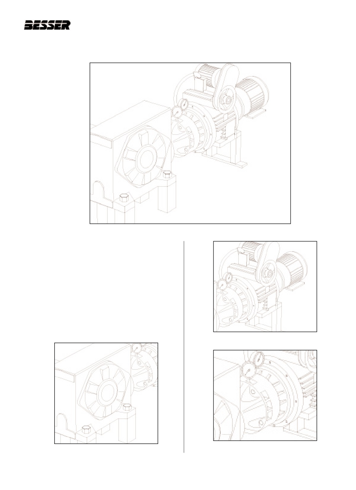
Figure 11.15 BLOCK MOVING DRIVE
The block moving drive is the independant drive (on the
R.H. side of your Dynapac) which powers the block
moving mechanism. As with all other components of
the machine, the block moving drive requires regular
maintenance and service to insure a continuous and
smooth working.
This sub-section will review maintenance and service
procedures for the four parts of the block moving mech-
anism: the reducer (see figure 11.16), the variator (see
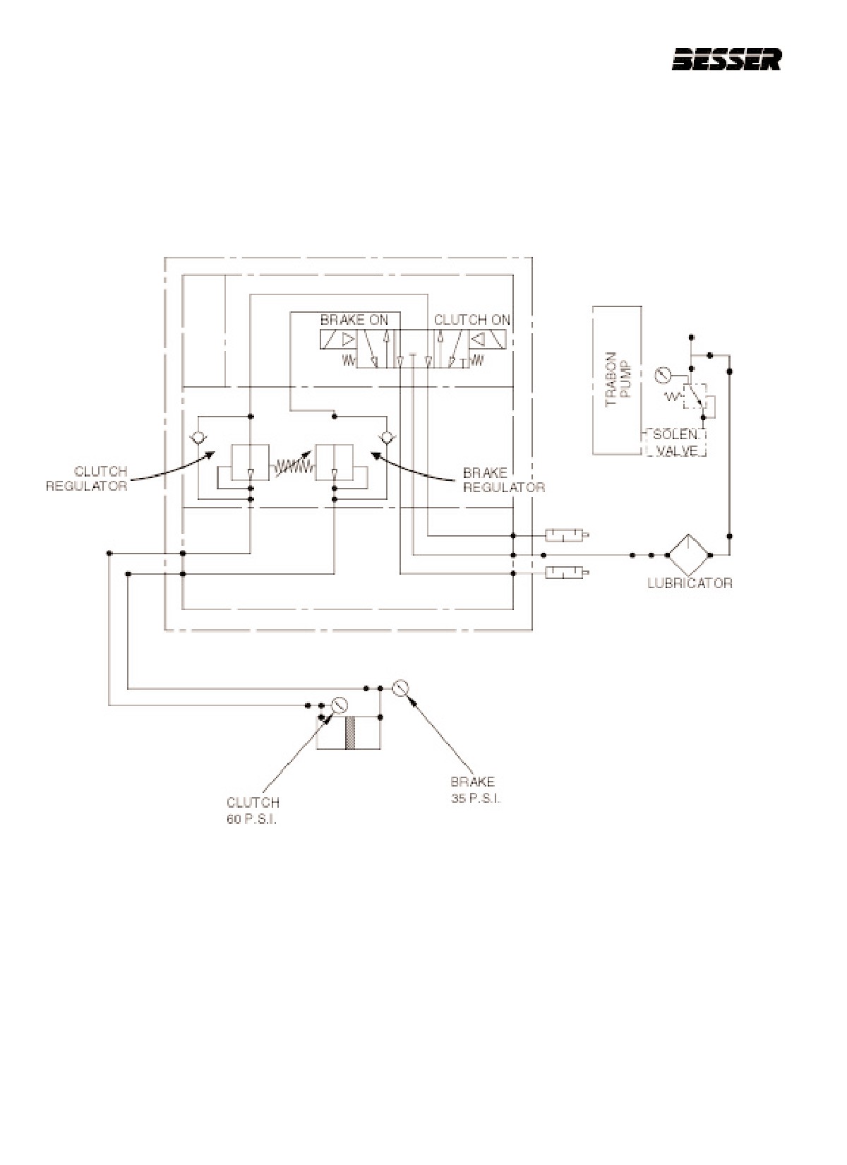
figure 11.17), the clutch/brake unit (see figure 11.18)
and the pneumatic system (see figure 11.19).
Figure 11.17 VARIATOR
Figure 11.18 CLUTCH/BRAKE UNIT
Figure 11.16 REDUCER
11-27
466361F9710US F1 29OC99
SECTION 11
MAINTENANCE
Figure 11.19
BLOCK MOVING DRIVE PNEUMATIC DIAGRAM - REFER TO 464701.
11-28
466361F9710US F1 29OC99
SECTION 11
MAINTENANCE
11.7.1.3
VENTILATION
CAUTION: Before doing any kind of
maintenance or service operation, shut
To prevent pressure build-up, a breather plug is fitted
all power off and lock out machine.
on top of the housing. Take care and check regularly
Always follow the lockout procedure list-
that this breather does not become clogged.
ed in the Safety section of this manual !
11.7.1.4
OIL CHANGE
11.7.1 REDUCER MAINTENANCE
A. The first oil change has to be made after 800
The reducer must be lubricated and greased at some
hours of operation. You can reuse the removed
predetermined intervals.
oil after filtering (use a 40µm filter).
When changing oil, choose your oil according to the oil
B. Subsequently, the next oil changes have to be
grade table (see table 11.14). The new oil must also
made every 8000 hours of operation or every
have the required viscosity according to temperature
two years max.
conditions (see table 11.15).
11.7.1.5
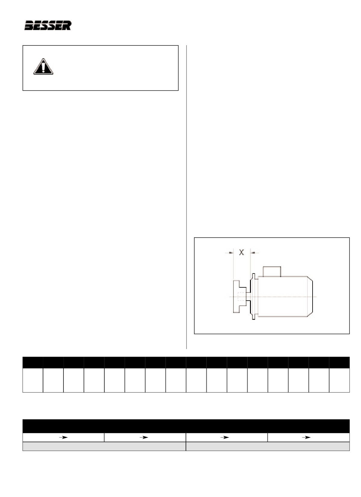
OUTPUT SHAFT DISTANCE
11.7.1.1
OIL FILLING
You must adjust the output shaft distance, called “dis-
Fill reducer with 0.8 gallons of oil. Check the oil level
tance X” (see figure 11.20), of the reducer before start-
plug position to fill the exact amount of oil.
ing it. Adjust the output shaft to have a distance "X" of
4.133" [105mm].
11.7.1.2
OIL DRAINING
Drain oil while unit is still warm. To facilitate oil draining,
remove filler plug.
Figure 11.20DISTANCE “X”
Aral
BP
Castrol
Chevron
Elf
Esso
Exxon
Fina
Gulf*
Mobil
Q8
Shell
Sunoco
Texaco
Total
Winter-shall
Degol
Energol
Alpha
Spartan
Reduct-
Spartan
Spartan
EP
Mobil
Sunep
Carter
Giran
Goya
Omala
Meropa
Ersolan
BG
GR-XP
SP
EP
elf
EP
EP
lubric.
Gear
1060
EP
220
220
220
220
220
220
220
220
220
SP 220
220
220
HD 220
630
ISO 220
220
*Gulf Ultima 220 for Canada
Table 11.14 OIL GRADE (EP GEAR OIL)
AMBIENT TEMPERATURE
+150F
+600F
-100C
+150C
+320F
+1050F
00C
400C
ISO VG 100 (AGMA 3EP)
ISO VG 220 (AGMA 5EP)
Table 11.15 OIL VISCOSITY
11-29
466361F9710US F1 29OC99
SECTION 11
MAINTENANCE
worn-out parts. For more detailed information on the
CAUTION: Before doing any kind of
variator, please refer to the manufacturer’s manual.
maintenance or service operation, cut
all power off and lock out machine.
11.7.3.1
OIL LEVEL
Always follow the lockout procedure list-
ed in the Safety section of this manual !
Oil level must be carefully watched as frequently as
possible. Keeping the oil at the required level is very
11.7.2 CLUTCH/BRAKE UNIT MAINTENANCE
important. The appropriate oil level is:
The Power Flo model CAB-CC is a pneumatic brake
Upper Red Mark : when not in operation
such that when air pressure is applied to the clutch port
Lower Red Mark : during operation
or to the brake port, the double acting piston will move
to engage the clutch and release the brake or move to
Make a daily inspection of the oil level.
engage the brake and release the clutch, respectively.
This model is made with a female nema C-face mount-
11.7.3.2
OIL CHANGE
ing on the clutch side and a male nema C-face on the
brake side.
Suggested interval for oil change for NA type Beier
variators is 500 hours after initial operation and every
The clutch/brake requires filtered and lubricated air
2,500 hours thereafter. This is the recommendation for
pressure. Also, the following items have a limited life
normal operation. Of course, oil should be changed
and may eventually need replacing:
more frequently whenever deterioration is detected,
Friction discs
since deterioration occurs in different operation hours
O-rings
subject to brand of oil, conditions of loading and sur-
Bearings
roundings.
Note that the maximum case temperature of the
11.7.3.3
OIL SELECTION
clutch/brake unit should be 1800F (820C).
The most important factor for the lubricant for the varia-
For more information on your clutch/brake unit and to
tor is its viscosity. When there are seasonal ambient
know how to assemble and disassemble the unit to
temperature changes, change oil periodically to meet
replace these parts, please refer to the manufacturer’s
the viscosity requirement due to the respective ambient
manual. To obtain a repair kit, spanner or fitting for the
temperature. Recommended oils to be used with Beier
unit, contact the manufacturer as indicated on the man-
variators are listed in table 11.16.
ual.
Note: For the maintenance, it is recommended that the
11.7.3 VARIATOR MAINTENANCE
maintenance records be attached to the drive.
Keep record of (1) Date of last oil change,
The SM- Beier variator unit of the block moving mecha-
(2) Brand of oil supplied, (3) Name of personnel
nism must be regularly lubricated and checked for
who did it, etc.
Recommended oils for use in NA Type variators - USE NO SUBSTITUTES
WARNING : DO NOT USE OILS CONTAINING E.P. ADDITIVES - OR AUTOMOBILE OILS
Ambient Temperature F0 (C0)
140 to 320
320 to 950
950 to 1220
Manufacturer
(-100 to 00)
(00 to 350)
(350 to 500)
Gulf Oil Corp.
Harmony 46AW
Harmony 68AW
Harmony
Harmony 150AW
Harmony 220
Exxon Co.
Nuto H46
Nuto H68
100AW
Terrestic 150
Terrestic 220
Mobil Oil Corp.
Mobil DTE 25
Mobil DTE 26
Terrestic 100
Mobil DTE
Mobil DTE
Mobil DTE Hvy
Extra Heavy
BB
Shell Oil Co.
Tellus 46
Tellus 68
Tellus 100
n.a
n.a.
Texaco Inc.
Rando 46
Rando 68
Regal R&O 100
Regal R&O 150
Regal R&O 220
Table 11.16 OIL GRADE AND VISCOSITY - NA TYPES
11-30
466361F9710US F1 29OC99
SECTION 11
MAINTENANCE
11.7.3.4
CHECK POINTS
C) Warning signals for replacement
During overhaul, examine the following compo-
During daily oil level inspection, give care to the follow-
nents carefully and replace them when the com-
ing abnormalities that may be the first signs of some
ponents show symptoms mentioned below in
faults/failures occuring in the drive.
table 11.17.
A)
Excessive temperature rise
Feel or measure temperature on the casing.
Allowable temperature rise measured on the sur-
face of the casing is 860F to 1050F over the ambi-
Component
Symptoms
ent temperature. Excessive temperature rise can
be attributed to various hidden causes. Please
Breakage
refer to section 11.7.3.6 (Variator troubleshooting)
Discolor due to seizure
for details.
Wear (reaching 20 microns)
Cone Discs
Flaw
Pitting/Spalling
B)
Abnormal sound
Galling
Abnormal sound is the sign of damage or failure
of components and it varies with the kind of com-
Wear of rim
ponent damage. Please refer to section 11.7.3.6
Pitting/Spalling/
(Variator troubleshooting) for details.
Galling
Discolor due to seizure
Flange Discs
C)
Oil leakage
Note: Slight pitting, spalling, flaw
Oil leakage arises from various causes such as
or burr can be corrected by an
worn oil seal, loose housing fit, excessive oil,
oil grind lapping stone.
faulty gasket, etc. Since oil leakage causes other
Wear
troubles, it must be quickly taken care of.
Fatigue
Bearings
Discolor
D)
Other abnormal performance
Broken Retainer
In addition to the above signs, several other
abnormal performances may be found during
Discolor due to seizure
operation though they may occur infrequently.
Fatigue of Key and Keyseat
Spine shafts
Fatigue on spline (if wear
They are increase of power consumption, vibra-
Input Shaft with Spline
exceeds 0.1mm in depth on
tion, fluctuating output speed, inability or difficulty
spline, replace)
of change speed, etc. Please refer to section
11.7.3.6 (Variator troubleshooting) for details.
Wear
Oil seal
Loss of elasticity
11.7.3.5
MAINTENANCE OVERHAUL
Pitting
Spalling
A) Overhauling period
Gears
Discolor due to seizure
After two years of continuous operation, an entire
Flaw
maintenance overhaul is recommended. This
include disassembly of the variator and inspection
Frequent speed change
of the wear on components. Please refer to the
causes wear in the hubs on
manufacturer’s manual for details.
the casing and cover which
Casing & Cover
supports swing shaft
Creep due to wear exceed-
B) Recommended replacement parts
ing 0.1mm requires replace-
The main components, which yield to wear during
menty
operation, are cone discs, flange discs, spline
shafts, gears, bearings and oil seals. Please
Table 11.17 OIL QUANTITY
refer to the manufacturer’s manual for details.
11-31
466361F9710US F1 29OC99