BESSER DYNAPAC 3 AT A TIME (466361F9710US). OPERATION / MAINTENANCE MANUAL - page 4
SECTION 8
OPERATING THE MACHINE
8-6
466361F9710US F1 29OC99
SECTION 9
GRAPHIC CONTROL STATION
SECTION 9
GRAPHIC CONTROL STATION
9.0
GRAPHIC CONTROL STATION
Note: In this section, the term "SLC" will be used in reference of the "Small Logic Controller"
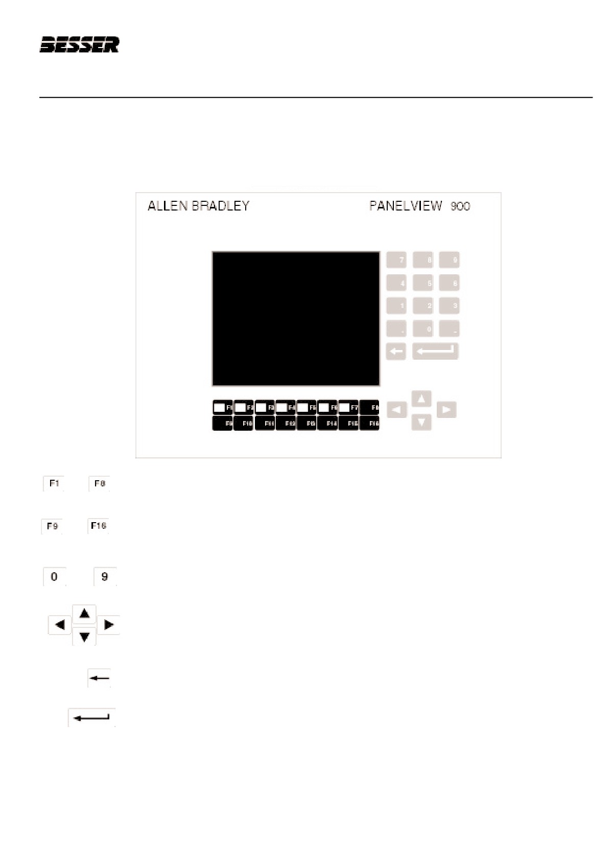
To
Use these keys to select a menu.
To
These keys are not in use.
To
These keys are used to enter a name or parameters
These keys are used to move cursor up and down and left to right.
This key allows the operator to erase a parameter.
This key is used to accept a parameter after it has been typed in.
466361F9710US F1 29OC99
9-1
SECTION 9
GRAPHIC CONTROL STATION
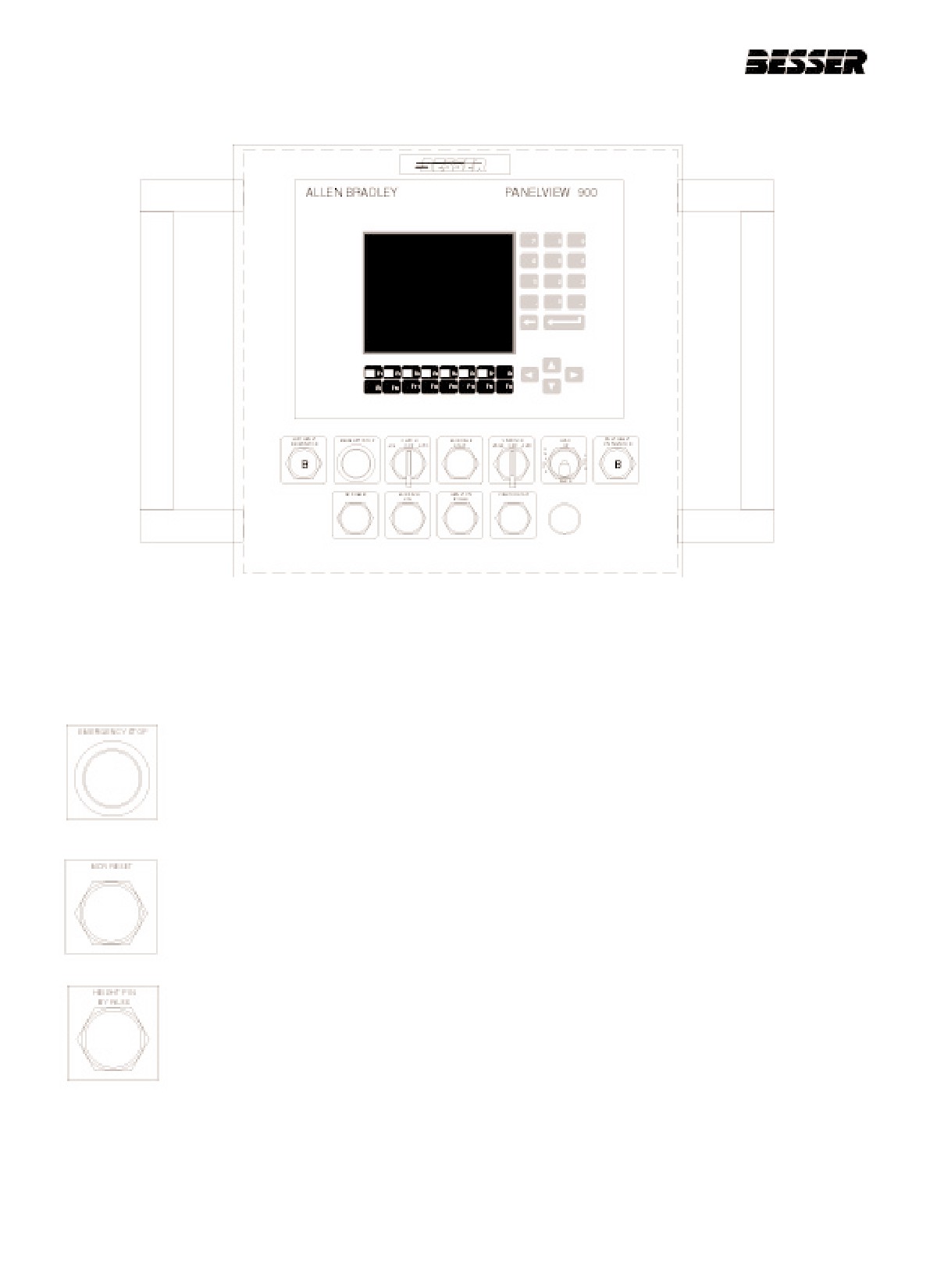
Figure 9.1
GRAPHIC CONTROL STATION.
Emergency stop,complete shut off of machine.
Needs to be pulled out to start the machine.
Master control delay reset.
Enables the machine to function (emergency button has to be pull out first).
This will override the height pins (simulate the meeting of height pins).
9-2
466361F9710US F1 29OC99

SECTION 9
GRAPHIC CONTROL STATION
HAND mode: vibration will start whenever switch is set to this position.
AUTO mode: vibration will occur during the appropriate time during the operation of machine.
Start vibrating motors but not the vibration itself.
To start actual vibration, use the "hand-off-auto" button.
Starts the main drive, but not the machine operation (clutch).
Jogs the machine only when the clutch selector switch is set to "Jog".
To start automatic operation.
At "Off", it stop the auto operation.
At "Jog", the machine can be jogged with the "Main drive jog" button.
OPTIONAL
Used to remove or install the mold with the stripper head.
Lock and unlock.
Raise and lower.
466361F9710US F1 29OC99
9-3
SECTION 9
GRAPHIC CONTROL STATION
9.1
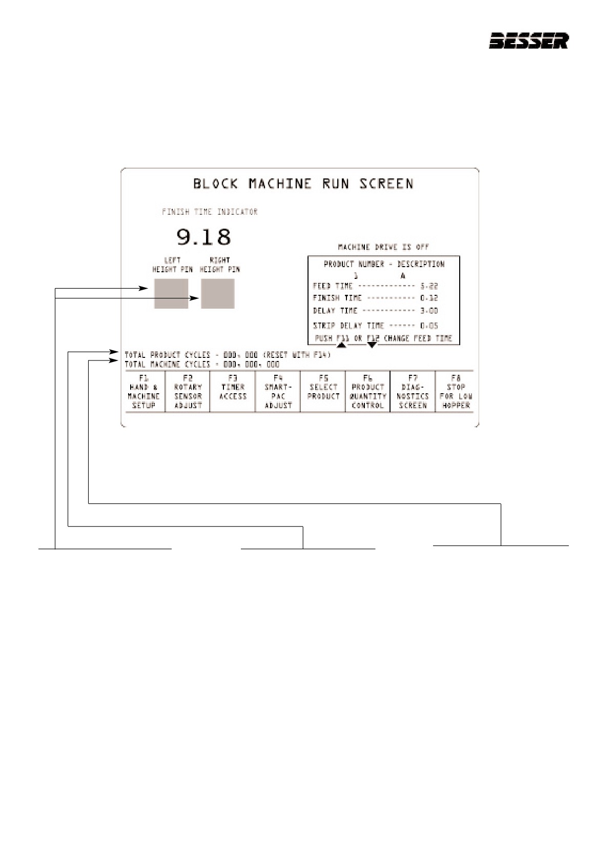
BLOCK MACHINE RUN SCREEN
Life time cycle counts (cannot
Red box will appear when
Number of cycles run by the
be reset).
height pins have made contact.
machine since the last product
change or since last reset.
Note: Use blue light indicators
on both sides of display screen
Note: Machine will ignore cycle
to monitor height pins. They
counts when vibrators are
are more accurate than the
turned off (dry cycles are not
ones on the display screen,
counted).
9-4
466361F9710US F1 29OC99
SECTION 9
GRAPHIC CONTROL STATION
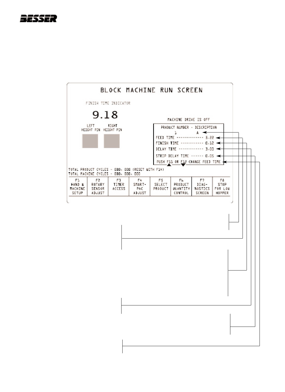
8 alpha-numeric digits are used
to name a particular product
FEED TIME
(ex.: B001 for block 1). Use
Amount of time the feed box is
keys 0 to 9 and A to F
stopped over the mold. This will
control the amount of material
(concrete) placed in the mold.
FINISH TIME
Preset time that you will expect desired fin-
ish time, from the moment stripper head
shoes hit material to when height pins
meet each other. Machine will adjust the
finish time by adjusting the autofeed
mechanism or the feed time (the operator
to select which one he prefers the machine
to change with (uses F1, F7 or F8).
DELAY TIME
The time of vibration after height
pins meet (F3 timer 2)
STRIP DELAY TIME
Time from the moment vibration
stops to when units are stripped
out of the mold.(F3 timer 3)
Use F11 & F12 KEYS to modify
feed time by 0.1 second
increments.
466361F9710US F1 29OC99
9-5
SECTION 9
GRAPHIC CONTROL STATION
9.2
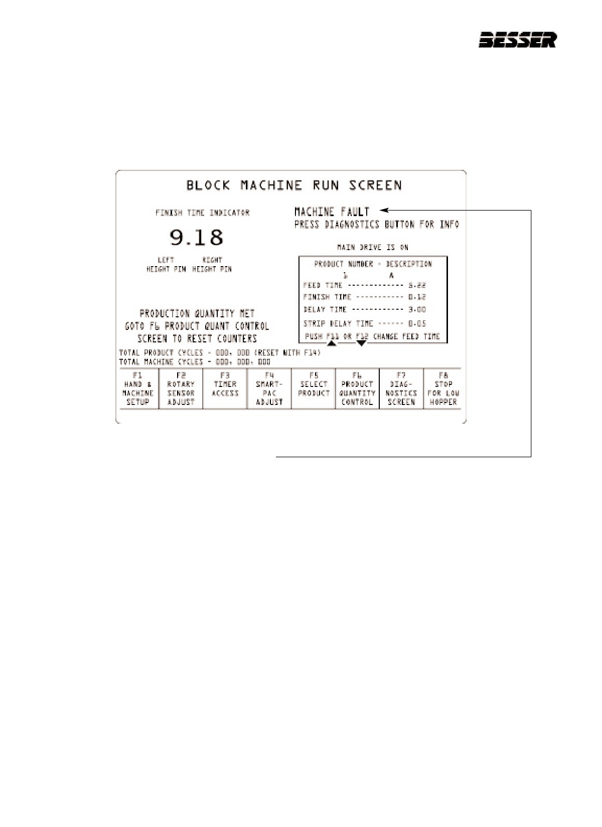
FAULT MESSAGE ON BLOCK MACHINE RUN SCREEN
This screen will be displayed every time a fault occurs.
When this message appears, follow this procedure:
1. Press F7 to inquire about the fault.
2. Correct the fault (see Trouble Shooting section).
3. Turn the clutch selector switch to "OFF".
4. Press the F9 key.
5. Turn clutch switch "ON"
The machine will sound an alarm and restart.
9-6
466361F9710US F1 29OC99
SECTION 9
GRAPHIC CONTROL STATION
9.3
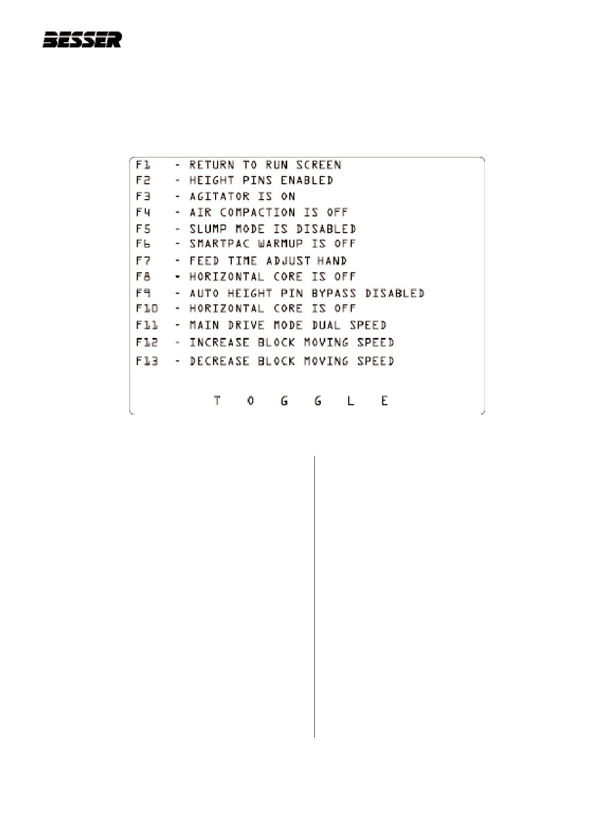
HAND & MACHINE SET UP F1
This screen allows the operator to turn some of the machine's components ON and OFF.
To access this screen from the RUN SCREEN, press F1.
F2: Normally enabled. The machine
F8: Turns the autofeed system ON or OFF
will not continue beyond point where height pins
meet. It can be useful for single cycle runs.
ref. timer
8 = manual adjustment increment
(time of travel)
F3: Turns the agitator ON or OFF .
ref. timer 10 = automatic adjustment increment
(time of travel)
F4: Turns the air compaction cylinders ON or OFF
F9: If enabled, a timer will control the finish time (refer
F5: If enabled, machine only needs 1 height pin to
to timer 23)
meet in order to continue cycle.
F10: Turns horizontal core ON and OFF (optional)
F6: Turns the pallet cleaner ON or OFF.
Note: The pallet cleaner is optional.
F11: Main drive speed selection (single or dual speed)
F7: If enabled, the feed time will be automatically
F12: *Only on Dynapac* Selects speed pf block
adjusted, otherwise, no adjustment will be made by
moving bars
the machine. The automatic feed time adjustment
will be made with 0.1 sec increments. If you wish
F13: *Only on Dynapac* Selects speed pf block
to change this increment, change value of register
moving bars
of N7:35 (see section 10.9, data table display
"F7"). Here, the normal value is equivalent to
0.1 seconds.
466361F9710US F1 29OC99
9-7
SECTION 9
GRAPHIC CONTROL STATION
9.4
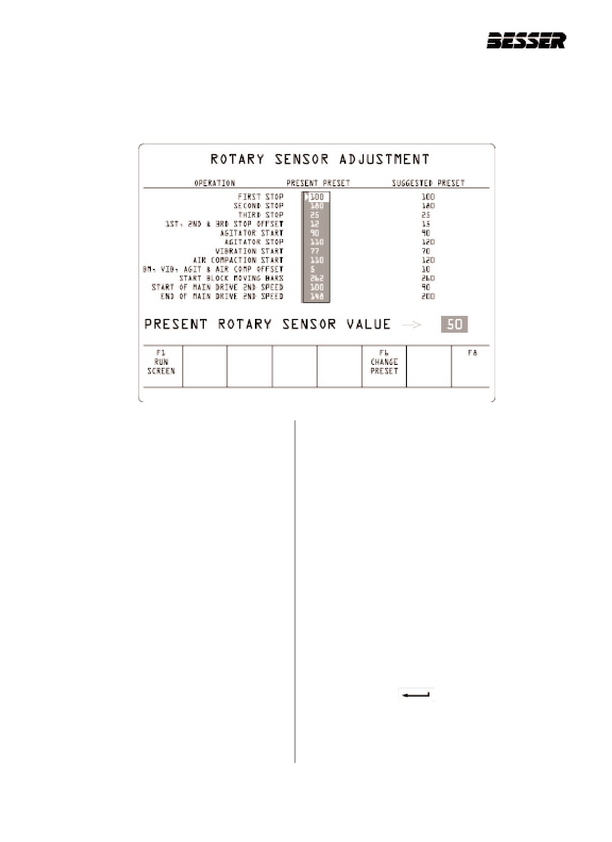
ROTARY SENSOR ADJUSTMENT F2
This screen allows the user to change the preset values of the rotary sensor. The rotary sensor is located at the end
of the main shaft. Its purpose is to synchronize the machine and all its components. This screen also allows the user
to acknowledge the present rotary sensor value. To access this screen from the RUN SCREEN,
press F2.
First stop:
Air compaction start:
Should occur when indicating 1000.
The location on the rotary sensor where the air compaction
starts (no stop location) (stop when height pins meet).
Second stop:
Should occur when indicating 1800.
BM, VIB, AGIT & Air comp offset:
Window for these components. (accuracy)
Third stop:
Ex.: If offset is 10o, BM bars can be between 250o and 260o
Should occur when indicating 250.
This value (10) will be subtracted from the value (250)
to give range of operation to the rotary sensor to deter-
1st, 2nd & 3rd stop offset:
mine a stop.
Window for stop position. (accuracy)
Ex.: If offset is 10o, 1st stop can be between 90o and 100o
Start block moving bars:
This value (10) will be subtracted from the stop value
The location on the rotary sensor where the block mov-
(100) to give range of operation to the rotary sensor to
ing bars start.
determine a stop.
Start of main drive 2nd speed & End of main drive
Agitator start:
2nd speed: Used with main drive frequency control.
The location on the rotary sensor where the agitator is
Establishes when you start and stop 2nd speed.
turned ON.
F6
Press this key to change any of the preset val-
Agitator stop:
ues.Use arrows to select. Use numbers to change
The location on the rotary sensor where the agitator is
values. Use
to make changes.
turned OFF.
PRESENT ROTARY SENSOR VALUE : 50
Vibration start:
It will indicate the rotary sensor location at present time.
The location on the rotary sensor where the vibrators start
(no stop location)(stop is controlled by a delay time).
9-8
466361F9710US F1 29OC99
SECTION 9
GRAPHIC CONTROL STATION
9.4.1
TO CHANGE PRESETS
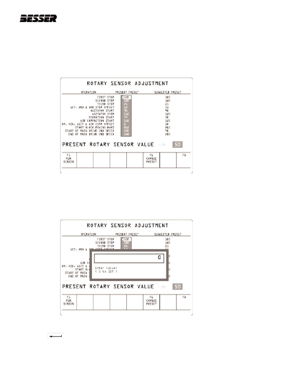
To change any of the rotary sensor value, follow these steps:
1. From the RUN SCREEN, press the F2 key.
The display will read:
2. Use the arrows to move the cursor to the item you wish to modify the Rotary Sensor value.
3. Press the F6 key.
The display will read:
4. Enter new Rotary Sensor value, from 0 to 359 (o to 359 degrees).
5. Press the
key.
466361F9710US F1 29OC99
9-9
SECTION 9
GRAPHIC CONTROL STATION
9.5
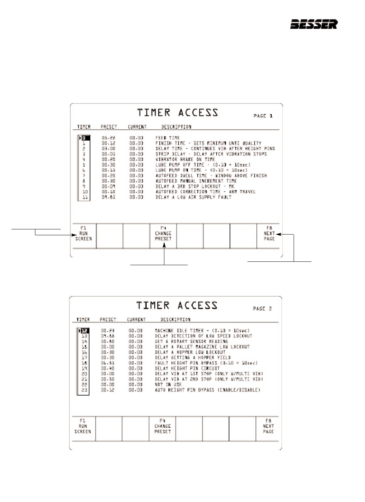
TIMER ADJUSTMENT F3
These two screens allow the operator to visualize and to change preset timer values. There are 24 timers (0 to 23)
which are accessible through these screens. Additional timers are accessible through the DATA TABLE DISPLAY
(F7 then F4). See appendix "A" for all timer addresses and descriptions. Each timer has a specific function related to
the machine's overall performance. The timers and their functions are listed on the next page. Timers 0 to 3 are the
most used timers; they control functions which are directly related to production. To access this screen from the RUN
SCREEN, press F3.
Press F1 to go
to previous page
or to return to
the RUN
SCREEN.
Use arrows on the keyboard to
Press F8 to go to the
Press F4 to change
select a timer.
next page (timers 12
preset value.
to 23).
9-10
466361F9710US F1 29OC99
SECTION 9
GRAPHIC CONTROL STATION
9.5.1
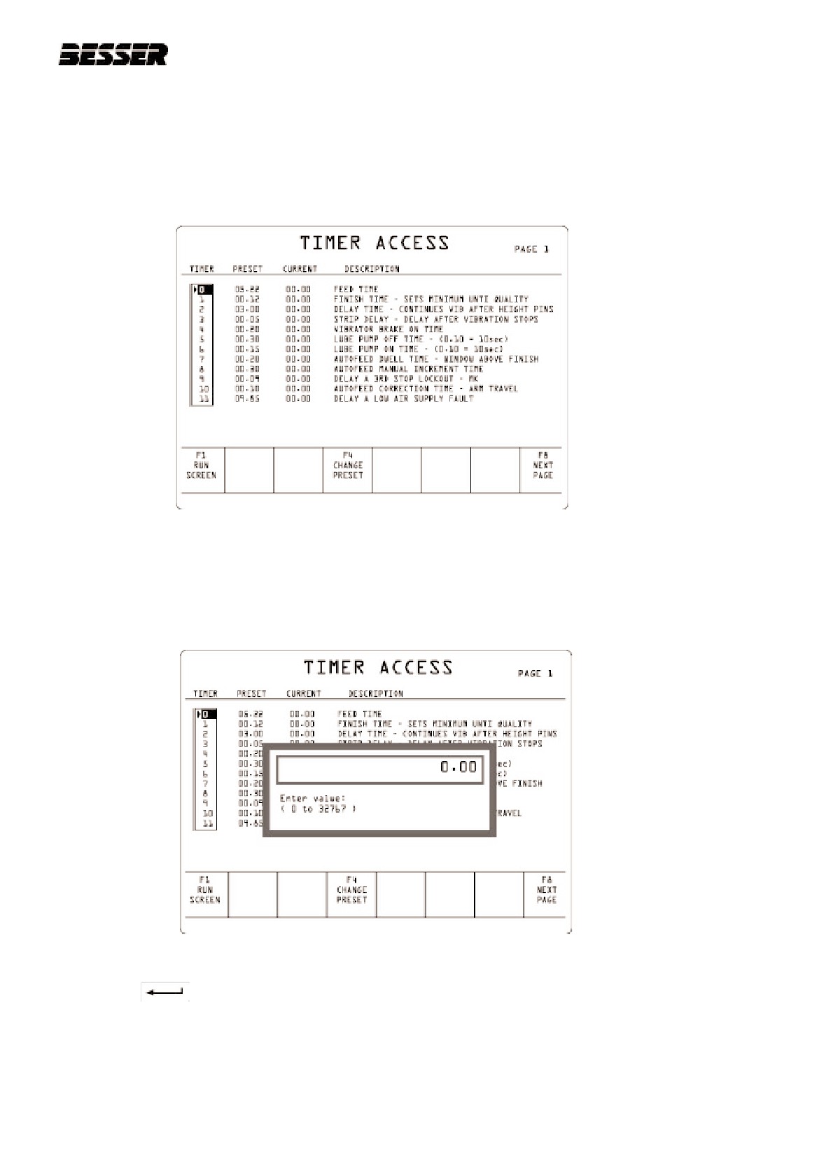
TO CHANGE PRESETS
To change any of the Timer value, follow these steps:
1. From the RUN SCREEN, press the F3 key.
The display will read:
2. Use the arrows to move the cursor to the timer of which you wish to modify the value.
3. Press the F4 key.
The display will read:
4. Enter new Timer value, from 0 to 32767.
5. Press the
key.
466361F9710US F1 29OC99
9-11
SECTION 9
GRAPHIC CONTROL STATION
TIMER
FUNCTION
0.
FEED TIME. Amount of time the feed box is stopped over the mold. This time controls the
amount of concrete placed in the mold.
1.
FINISH TIME. Preset time that you will expect desired finish time. Finish time is from the moment
stripper head shoes hit material to when height pins meet. Machine will adjust the finish time by
adjusting either the autofeed mechanism or the feed time.
2.
DELAY TIME. Amount of time of vibration after height pins meet.
3.
STRIP DELAY TIME. Delay between time when vibration stops and when units are stripped out
of the mold.
4.
VIBRATOR BRAKE ON TIME. The amount of time the vibrator brake is energized.
Note: If your machine is equipped with Smartpac, timer 4 is not used.
5.
LUBE PUMP OFF TIME. This is the time (over a period of 1 minute) that the lubrication pump is
OFF. (IMPORTANT: 0.01 = 1 second) Note: This is the timer that should be used to adjust lubri-
cation time.
6.
LUBE PUMP ON TIME. This is the time (over a period of 1 minute) that the lubrication pump is
ON. (IMPORTANT: 0.01 = 1 second) Note: Use timer 5 above to adjust lubrication time.
Timer 5 + timer 6 = total cycle time of lubrication pump.
7.
AUTOFEED DWELL TIME. If the finish time is greater than this amount, the autofeed will not
adjust the finish time.
Ex.: Finish time = 1 second
Timer 7 =
0.40 second
If finish time is between 1 sec. and 1.4 sec., the autofeed will not adjust finish time.
If finish time is 1.50 sec., autofeed mechanism or feed time will be incremented down.
If finish time is 0.9 sec., autofeed mechanism or feed time will be incremented up.
Note: See section 9.3: “Hand & machine setup” - F7 and F8.
8.
AUTOFEED MANUAL INCREMENT TIME. The amount of autofeed correction in manual mode.
Note: This is necessary to manually increase or decrease the amount of travel done by the
autofeed mechanism each time you manually operate it. This timer is related to the
ruler on top of the autofeed mechanism.
9.
DELAY A 3RD STOP LOCKOUT. After the product is stripped out of the mold, it is possible
that a third stop is necessary. The third stop may be required for slow product delivery. The delay
you will be presetting here will be considered acceptable. Above this time (9 seconds), the computer
will show a fault signal.
10.
AUTOFEED CORRECTION TIME - ARM TRAVEL - Same as timer 8 but with the automatic
mode on.
11.
DELAY A LOW AIR SUPPLY FAULT. Won't stop the machine in case of small air pressure
fluctuation. If the air pressure fluctuation lasts longer than this preset time, the SLC will show a
fault.
9-12
466361F9710US F1 29OC99
SECTION 9
GRAPHIC CONTROL STATION
TIMER
FUNCTION
12.
MACHINE IDLE TIMER. If your machine is part of a plant integration, this timer will be used.
No fault condition created.
13.
DELAY DETECTION OF LOW SPEED LOCKOUT. In case of mechanical jam or underspeed
condition, the machine will stop after this delay.
14.
GET A ROTARY SENSOR READING. This timer is preset and should not be adjusted by the
operator.
15.
DELAY A PALLET MAGAZINE LOW LOCKOUT. The amount of acceptable time the magazine is
low on pallets before a fault is actuated.
16.
DELAY A HOPPER LOW LOCKOUT. The amount of acceptable time the hopper is low on
material before a fault is actuated.
17.
DELAY GETTING A HOPPER YIELD. Used in plan integration.
18.
NOT IN USE.
19.
DELAY HEIGHT PIN CKT - IGNORE PIN BOUNCE. Amount of time before height pin circuit are
enabled. Used to ignore pin bounce on low height products.
20.
DELAY VIBRATION AT 1ST STOP. Delay of normal vibrating start at first stop (feed vibration).
Note: Only with double vibration
21.
DELAY OF 2nd STOP VIBRATION. Delay of normal vibrating start at second stop (finish
vibration).
Note: Only with double vibration
22.
NOT IN USE.
23.
AUTO HEIGHT PIN BYPASS. This period would be the desired finish time. This is possible only
if the auto height pin bypass has been enabled. To enable or disable the auto height pin bypass,
go to screen: “Hand & machine set-up” (section 9.3 - Function F9).
466361F9710US F1 29OC99
9-13
SECTION 9
GRAPHIC CONTROL STATION
9.6
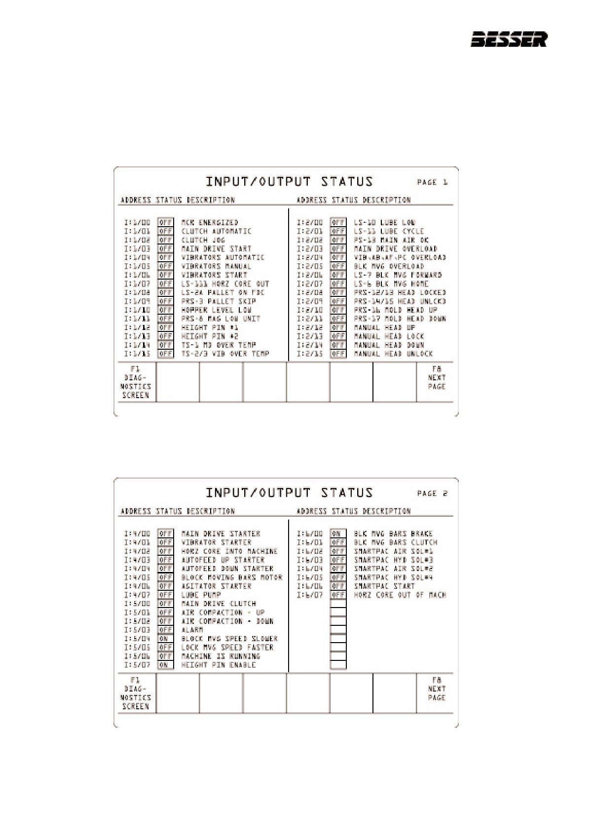
INPUT / OUTPUT STATUS
These screens represent the status of all electrical components on the block machine. They can be used to isolate
one component on the machine or to locate an electrical fault on one of the components.
To access this screen from the RUN SCREEN, press F7 to go to the Diagnostics screens, then press F3.
Press F8 to go to the next page.
9-14
466361F9710US F1 29OC99
SECTION 9
GRAPHIC CONTROL STATION
9.7
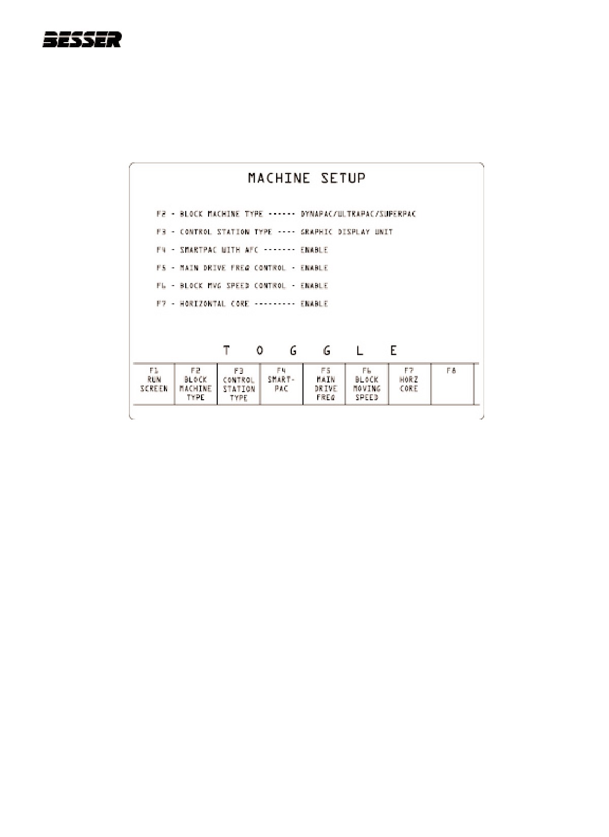
MACHINE SETUP
Machine Setup enables the user to enter some of the basic data into the machine such as the type of machine and
control station. It is also possible to enable and disable some of the machine’s components. This is done when a
new start-up is done or when a lost program or SLC-500 malfunction occurs.
To access this screen from the RUN SCREEN, press F16.
466361F9710US F1 29OC99
9-15
SECTION 9
GRAPHIC CONTROL STATION
9.8
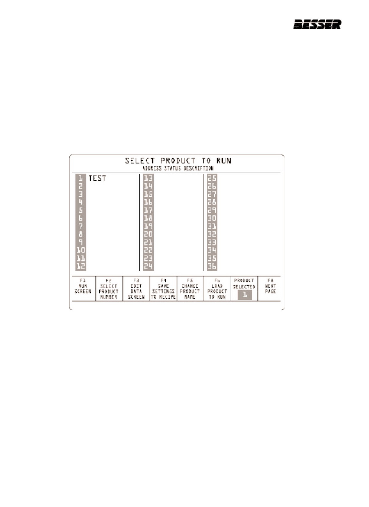
PRODUCT TABLE F5
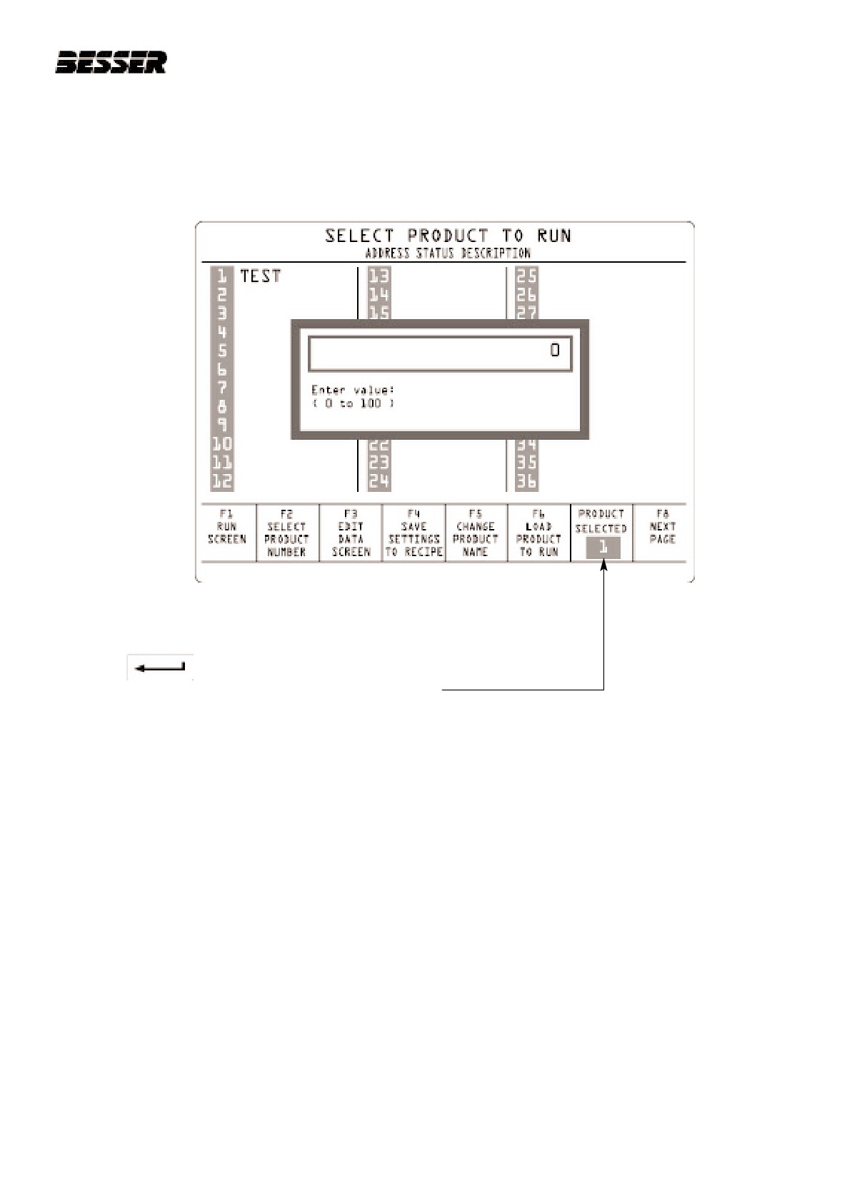
This menu allows you to store and retrieve preset recipes which include Feed time, Finish time, Delay time, and Strip
delay time and other parameters. There is a possibilty of 100 product numbers. To access this menu from the RUN
SCREEN, press F5. To return to the RUN SCREEN, press F1
With this menu, you may:
- Enter into the SLC memory a name for different products.
- Enter preset recipes for each of those products.
- Modify any preset recipe for any product.
The screen below shows an example of a product number. As an example, we gave the name TEST. From here,
the user may select a product number, edit recipe data, save recipe settings, change product name and load product
to run..
F1
Return to RUN SCREEN.
F2
SELECT PRODUCT NUMBER: Used to select an existing product number.
F3
EDIT DATA SCREEN: Used to enter data such as product height, unit types etc.
F4
SAVE SETTINGS TO RECIPE: Used to save recipe settings, once you have entered data for recipe.
F5
CHANGE PRODUCT NAME. Since each product has a name, it is possible to change a product name with this
function.
F6
LOAD PRODUCT TO RUN: .Machine won't use the recipe parameters until you load product to run.
9-16
466361F9710US F1 29OC99
SECTION 9
GRAPHIC CONTROL STATION
9.8.1
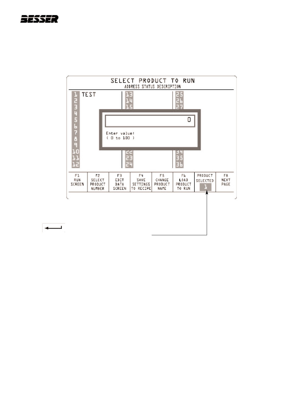
TO SELECT A PRODUCT NUMBER:
1. From the SELECT PRODUCT SCREEN, press the F2 key.
The display will read:
2. Enter product number you wish to change, edit or load. (from 0 to 100)
3. Press
The screen will now show the selected product number.
466361F9710US F1 29OC99
9-17
SECTION 9
GRAPHIC CONTROL STATION
9.8.2
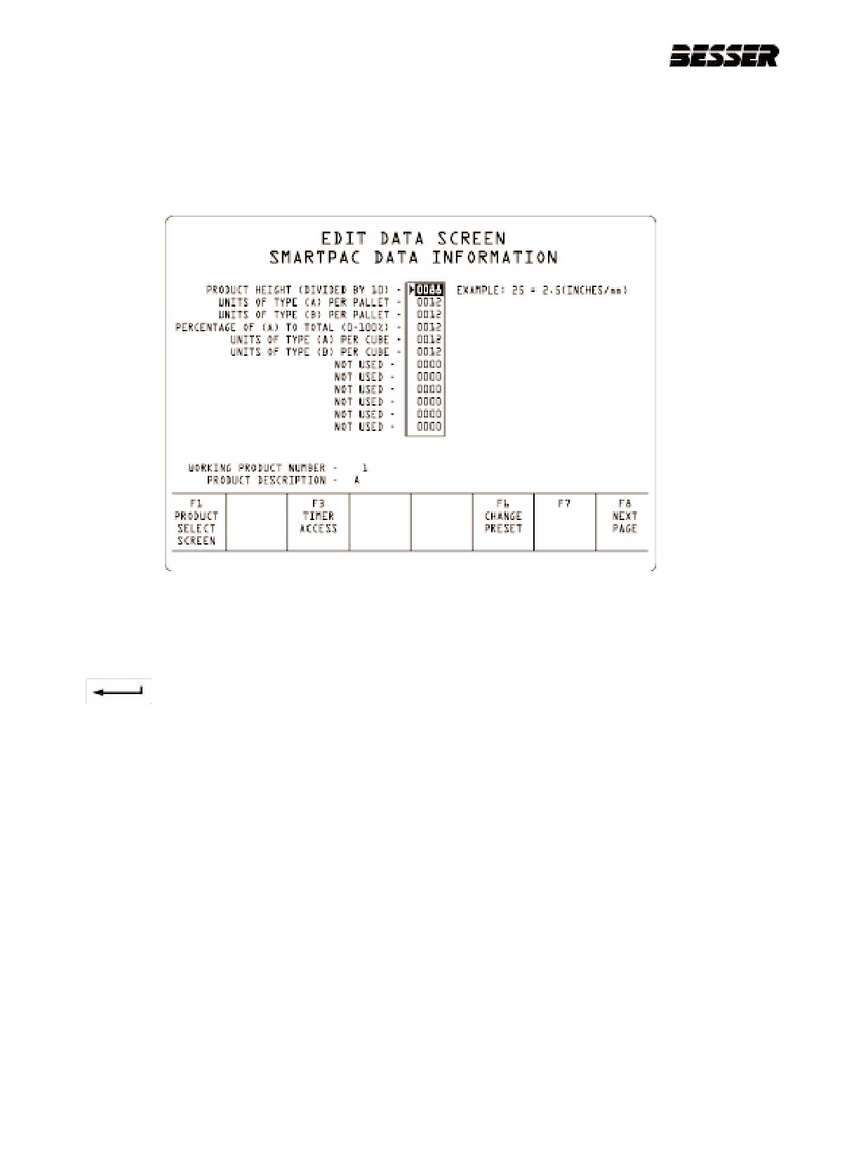
TO EDIT RECIPE DATA:
1. From the SELECT PRODUCT SCREEN, press the F3 key.
The display will read:
2. Use arrows to move cursor to any of the preset you wish to modify.
3. Press the F6 key to change preset. Value can be from 0 to 65535.
4. Press
to enter preset into memory.
From this screen, you may also access the timers by pressing F3 and the Smartpac settings by pressing F8.
Once you are finished entering data for presets, press F1 key to return to previous screen.
9-18
466361F9710US F1 29OC99
SECTION 9
GRAPHIC CONTROL STATION
9.8.3
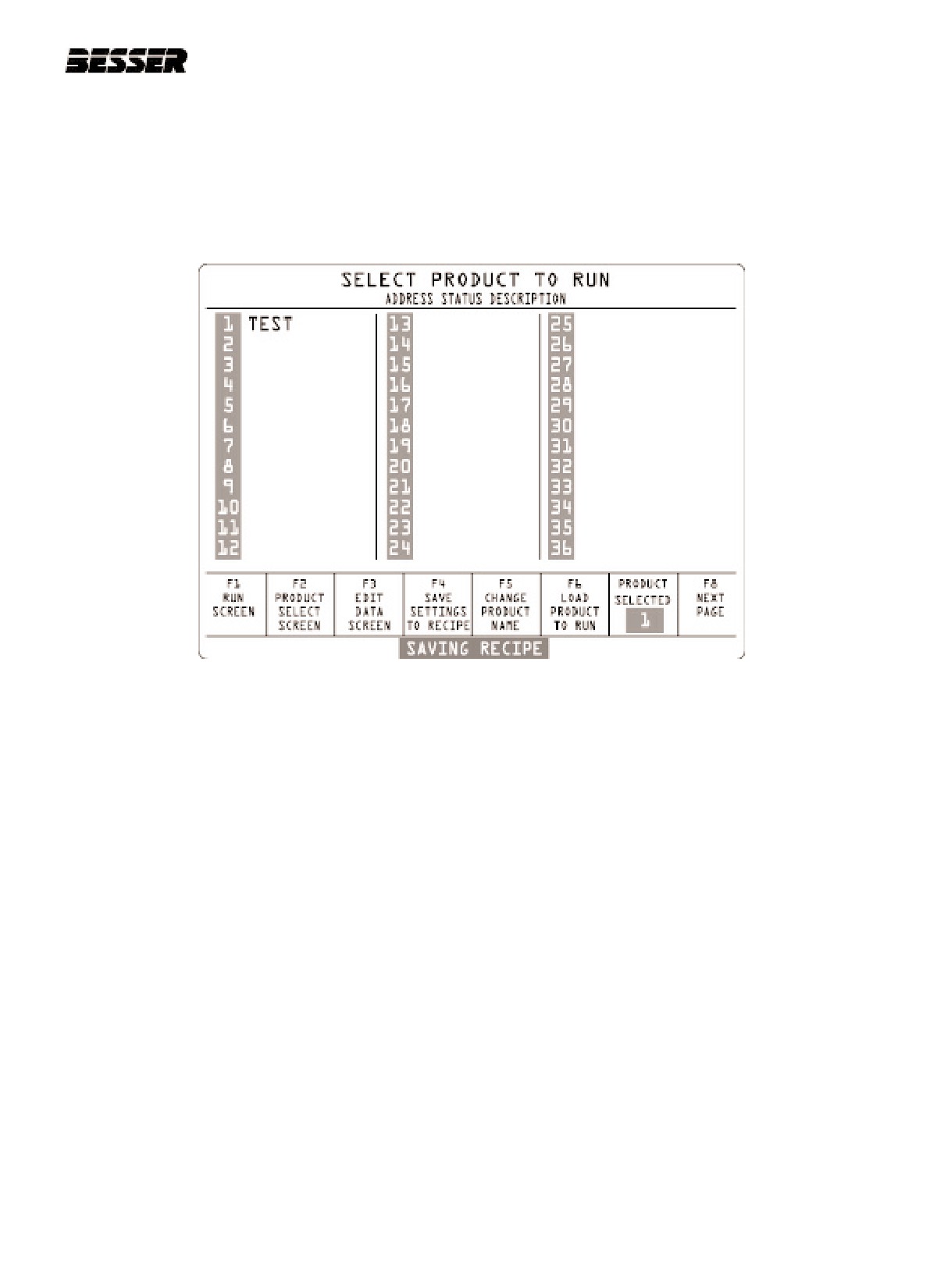
TO SAVE SETTINGS TO RECIPE:
1. From the SELECT PRODUCT SCREEN, press the F4 key.
The display will read:
466361F9710US F1 29OC99
9-19
SECTION 9
GRAPHIC CONTROL STATION
9.8.4
TO ENTER OR CHANGE PRODUCT NAME:
This function is used to load the product number currently selected.
1. From the SELECT PRODUCT SCREEN, press the F3 key.
The display will read:
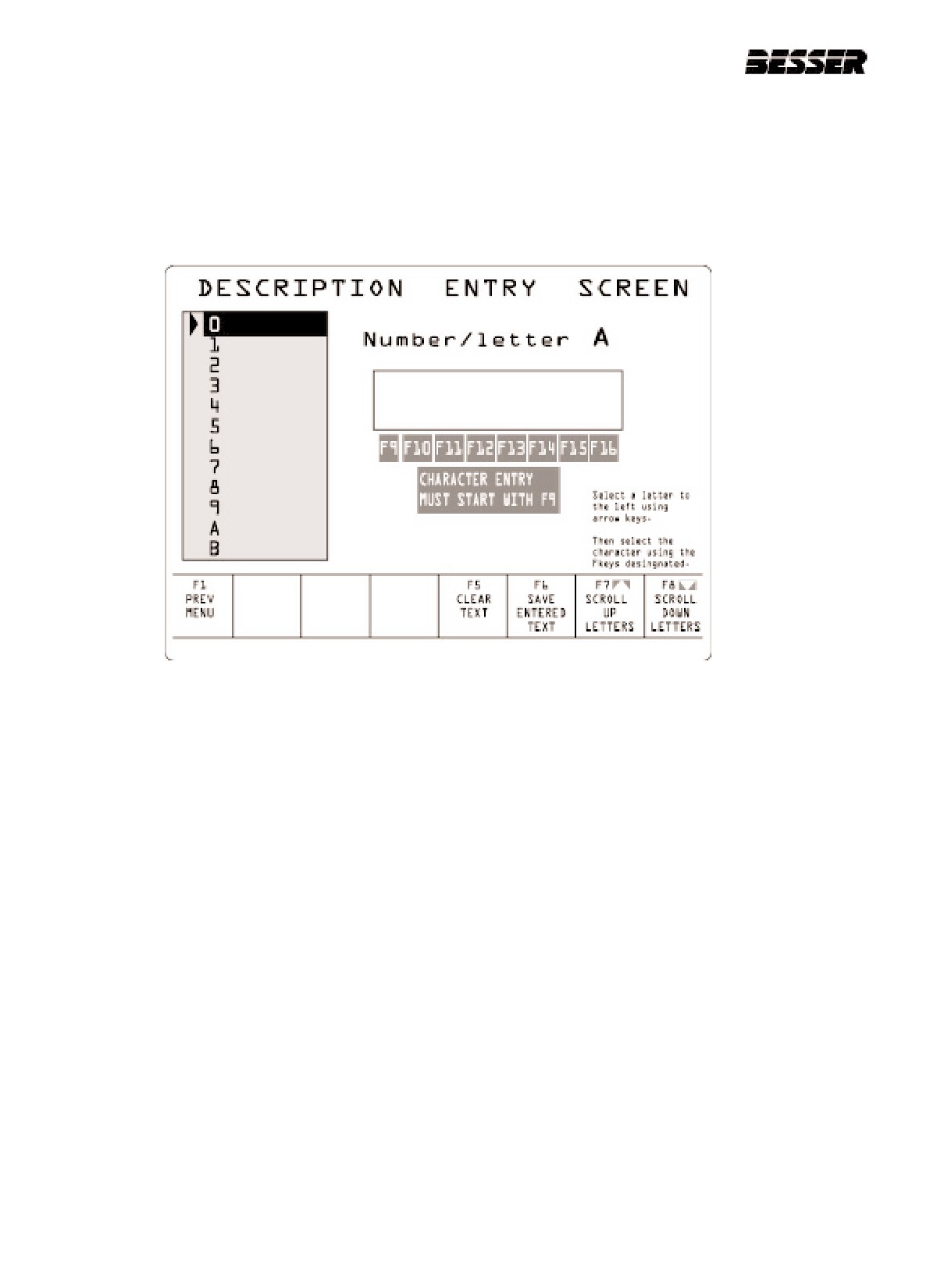
2. Use arrows to move cursor to any number from 0 to 9 or any letter from A to Z. A “space” and “end text” is also
available.
3. Press the F9 key.
4. Use arrows to move cursor to any other character listed above.
5. Press the F10 key.
6. Repeat same steps using F10, F11, F12, F13, F14, F15 and F16 until 8 character name is complete.
7. Press the F6 key to save entered text.
Note:
- At any time, press F5 key to erase all character in box.
- You may also use F7 and F8 keys to scroll up and down.
9-20
466361F9710US F1 29OC99
SECTION 9
GRAPHIC CONTROL STATION
9.8.5
TO LOAD PRODUCT TO RUN.
1. From the SELECT PRODUCT SCREEN, press the F6 key.
The display will read:
2. Enter product number you wish to change, edit or load. (from 0 to 100)
3. Press
The screen will now show the selected product number.
466361F9710US F1 29OC99
9-21

SECTION 9
GRAPHIC CONTROL STATION
9.9
CYCLE TIMER
This menu allows the operator to monitor each machine cycle through a graph. It will indicate the time it took to do
each cycle and also it will show the average time for the last 10 cycles.
To access this screen from the RUN SCREEN, press F7. Then press the F4 key.
The display will read:
Average cycles per minute
Average time it takes the machine to complete
one average cycle (based on the last 10 cycles)
Time it takes the machine to complete one full
cycle. Example here: 8.55 seconds
Total amount of time the machine has been run-
ning. Can be reseted by using the F8 key.
9-22
466361F9710US F1 29OC99
SECTION 9
GRAPHIC CONTROL STATION
9.10 DIAGNOSTICS F7
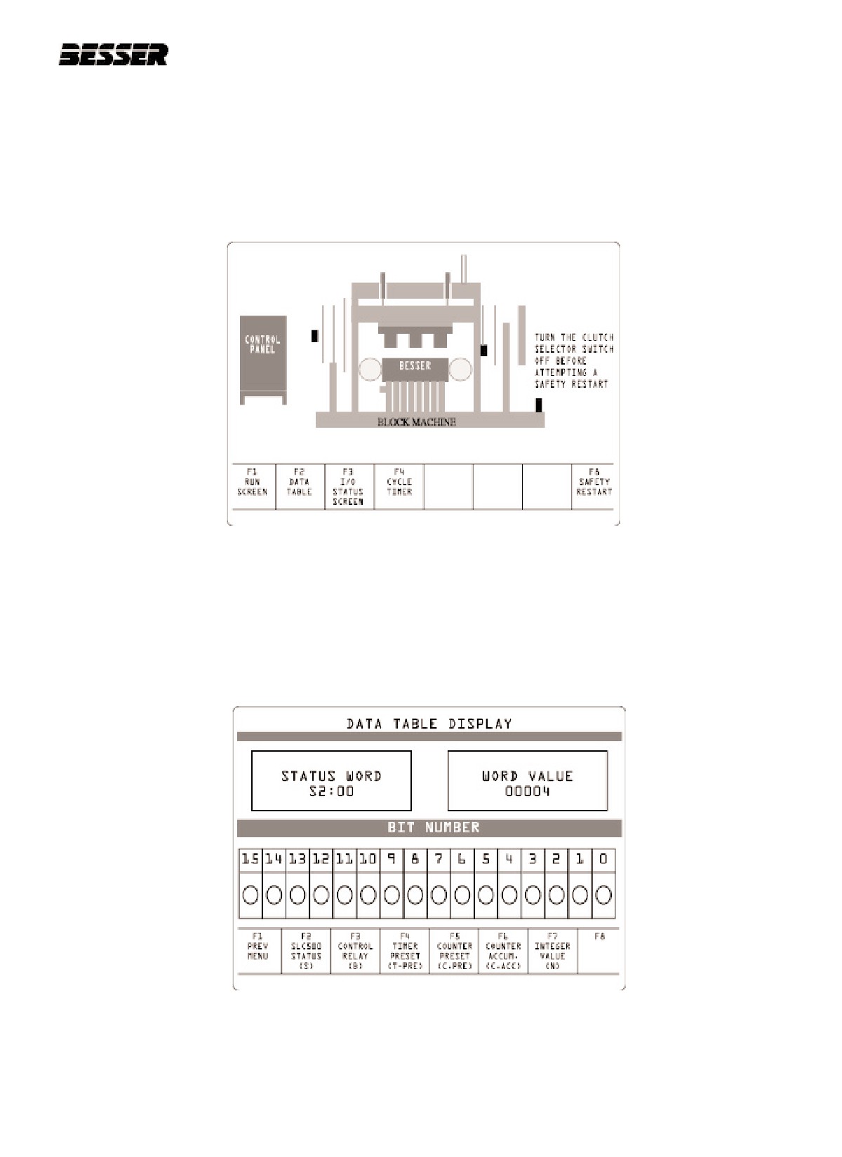
This menu allows the operator to monitor the machine once a fault condition has occurred.
To access this screen from the RUN SCREEN, press F7. To return to the RUN SCREEN, press F1
The display will read:
This screen will show a diagram of the machine and indicate where the fault is located.
From this screen, you can access the Data table. The Data table enables the operator to monitor or change parame-
ters concerning: Control relays, Timer and Counter presets as well as Integer value.
To access the Data table, press the F2 key.
The display will read:
From this screen, the operator has access to 6 different menus. See next pages for description of these menus.
466361F9710US F1 29OC99
9-23
SECTION 9
GRAPHIC CONTROL STATION
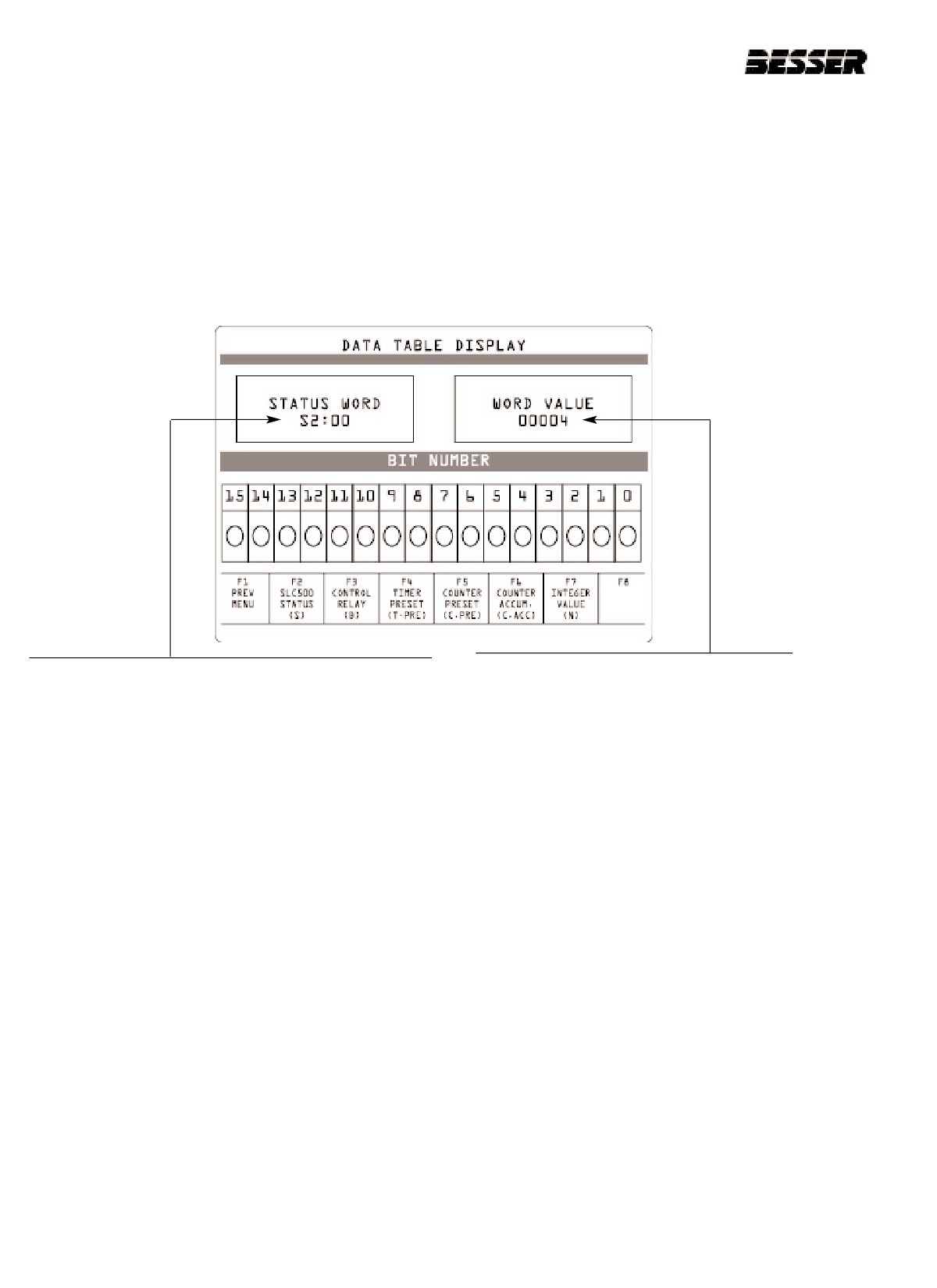
To change or monitor any of the parameters, press any of the keys between F2 and F7.
9.10.1 TO MONITOR A SLC500 STATUS (F2):
From the RUN SCREEN, press F7.
1. Press the F2 key.
The display will read:
The SLC shows here the word preset value.
2. Press the F2 key.
3. Enter a status word here then press ENTER. A word
is an address to a memory location fora timer, a
counter, an integer value or a control relay. Refer to
appendix A for address location.
To change a preset value:
4. Press the F16 key.
5. Enter new value.
6. Press ENTER.
9-24
466361F9710US F1 29OC99
SECTION 9
GRAPHIC CONTROL STATION
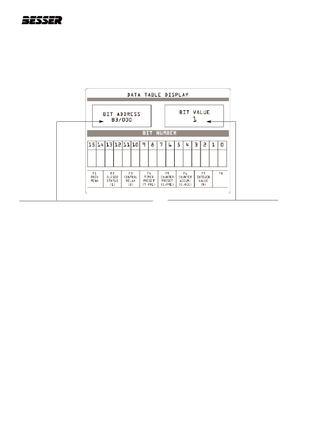
9.10.2 TO MONITOR A CONTROL RELAY (F3):
From the RUN SCREEN, press F7.
1. Press the F2 key.
The display will read:
2. Press the F3 key.
The SLC shows here bit value for this address.
0 = OFF
3. Enter a control relay bit address here then press
1 = ON
ENTER. Refer to the logic diagram in appendix A for
proper address location.
To change a preset value:
4. Press the F16 key.
5. Enter new value.
6. Press ENTER.
466361F9710US F1 29OC99
9-25
SECTION 9
GRAPHIC CONTROL STATION
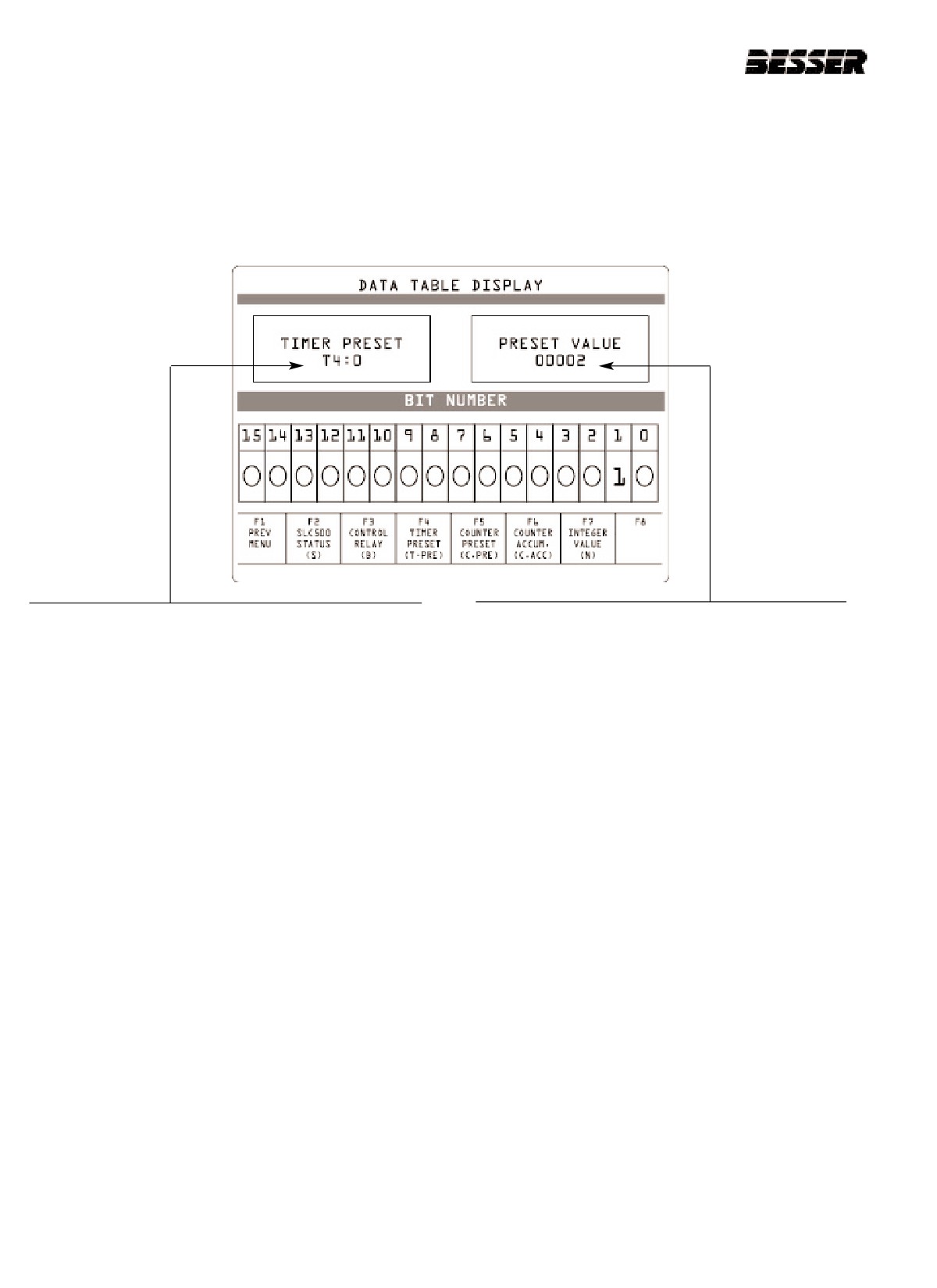
9.10.3 TO MONITOR OR CHANGE A TIMER PRESET (F4):
From the RUN SCREEN, press F7.
1. Press the F2 key.
The display will read:
2. Press the F4 key.
The SLC shows here the preset value for this timer.
NOTE: A time base should be taken into account when
3. Enter a Timer address here then press ENTER.
establishing true time value.
(Example here is 0)Refer to appendix A for proper
address location and description.
To change a preset value:
4. Press the F16 key.
5. Enter new value.
6. Press ENTER.
9-26
466361F9710US F1 29OC99
SECTION 9
GRAPHIC CONTROL STATION
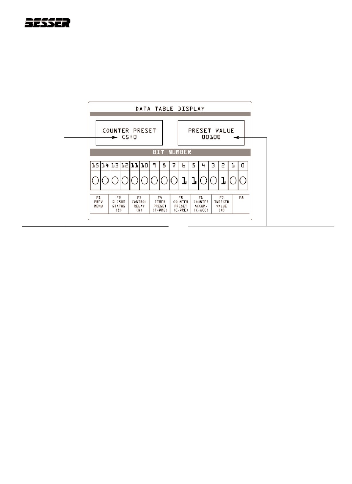
9.10.4 TO MONITOR OR CHANGE A COUNTER PRESET (F5):
From the RUN SCREEN, press F7.
1. Press the F2 key.
The display will read:
2. Press the F5 key.
The SLC shows here the preset value for this counter.
3. Enter a Counter address here then press ENTER.
(example here is 5) Refer to appendix A for proper
address location and description.
To change a preset value:
4. Press the F16 key.
5. Enter new value.
6. Press ENTER.
466361F9710US F1 29OC99
9-27
SECTION 9
GRAPHIC CONTROL STATION
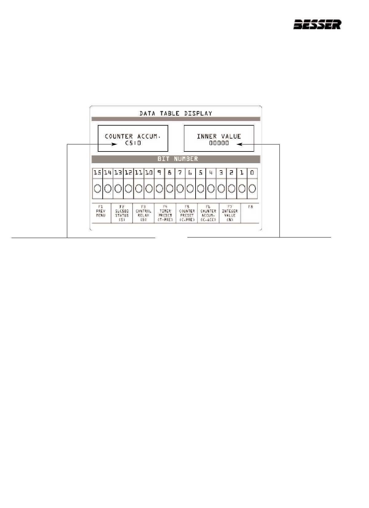
9.10.5 TO CHANGE THE ACCUMULATED VALUE OF A COUNTER (F6):
From the DATA TABLE DISPLAY SCREEN,
1. Press the F2 key.
The display will read:
To change the accumulated value of a counter:
The SLC shows the inner value for this counter.
2. Press the F16 key.
3. Enter new value.
4. Press ENTER.
9-28
466361F9710US F1 29OC99
SECTION 9
GRAPHIC CONTROL STATION
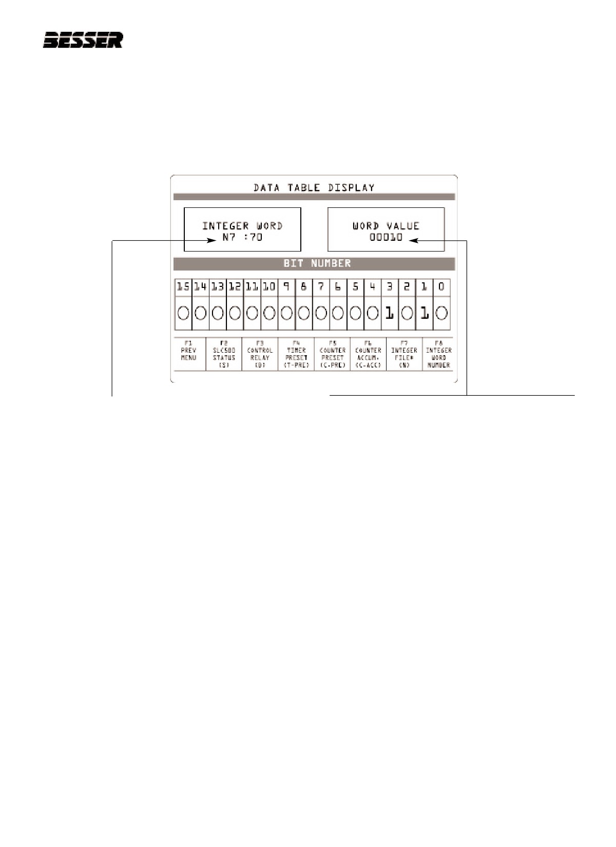
9.10.6 TO MONITOR OR CHANGE A INTEGER WORD VALUE (F7):
From the RUN SCREEN, press F7.
1. Press the F2 key.
The display will read:
2. Press the F7 key.
The SLC shows the word value for this Integer.
3. Press the F7 key.
4. Enter a Integer file number here then
press ENTER.(example here is 7)
5. Press the F8 key.
6. Enter a word number then press ENTER (example
here is 70)
7. Press F16 to change word value.
Refer to the logic diagram in appendix A
for proper address location and description.
466361F9710US F1 29OC99
9-29
SECTION 9
GRAPHIC CONTROL STATION
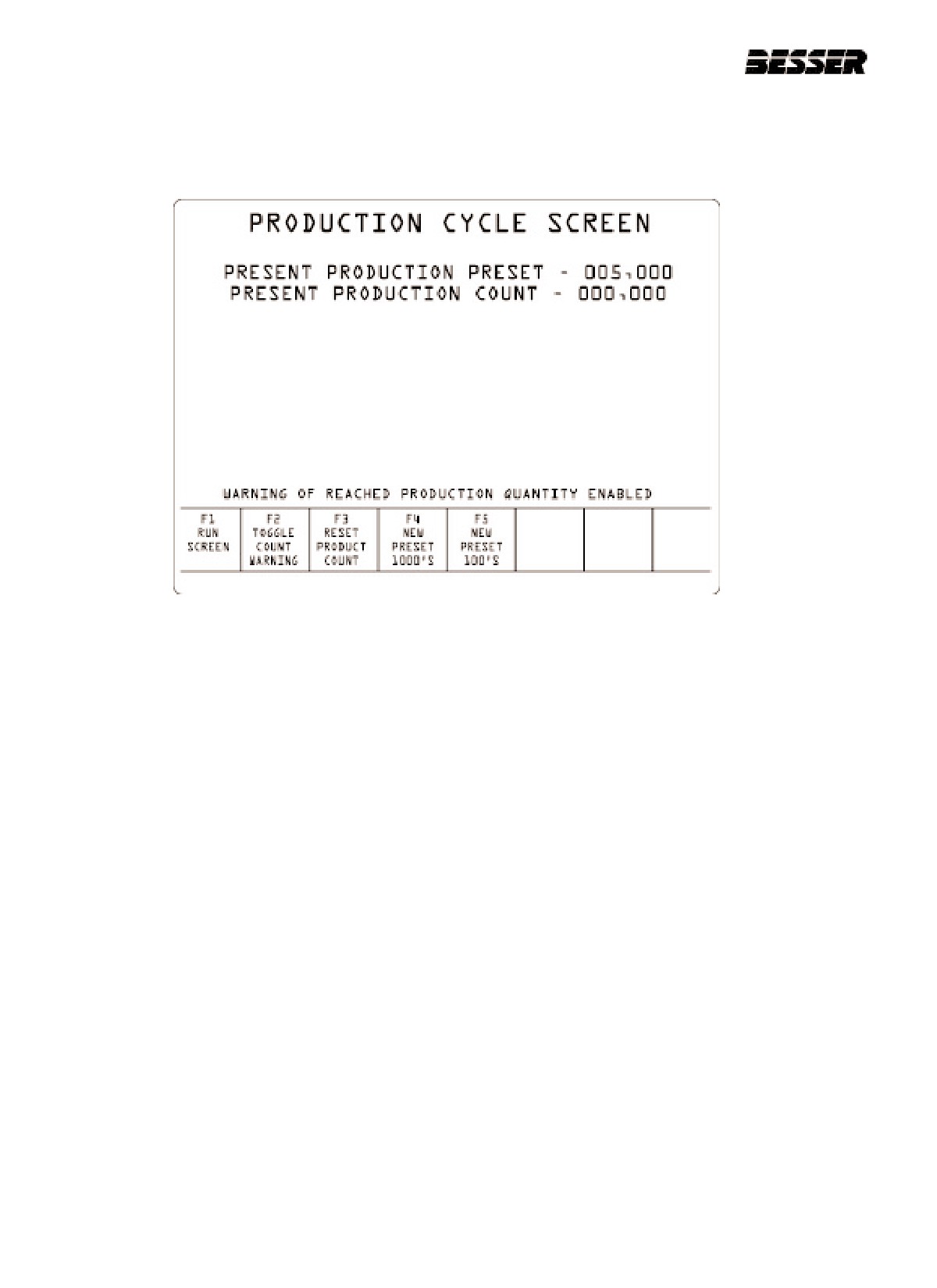
9.11 PRODUCT QUANTITY CONTROL F6
This menu allows the operator to enter a desired preset production count and to set the count warning.
To access this screen from the RUN SCREEN, press F6.
9.11.1 TO HAVE THE PRODUCTION COUNT WARNING SHOW:
Press the F2 key to toggle between Disabling and Enabling the production count warning.
9.11.2 TO RESET THE PRODUCTION COUNT:
Press the F3 key and the production count will be reset.
9.11.3 TO SET A NEW PRODUCTION COUNT WARNING:
1. Press the F4 key to set new preset in the thousands.
2. Enter a new present production preset (1=1000
/
999 = 999,000)
3. Press ENTER.
4. Press the F5 key to set new preset in the hundreds.
5. Enter a new present production preset (1=1
/
999 = 999)
6. Press ENTER.
When the machine cycle count will have reached this preset value, a warning will show on the screen if you have
enabled this warning.
This warning is shown on the next page.
Once this warning has occurred, press any key to return to the RUN SCREEN.
Note: This will automatically reset the production count to 0.
9-30
466361F9710US F1 29OC99

SECTION 9
GRAPHIC CONTROL STATION
466361F9710US F1 29OC99
9-31
SECTION 9
GRAPHIC CONTROL STATION
9.12 SMARTPAC ADJUSTMENT F4
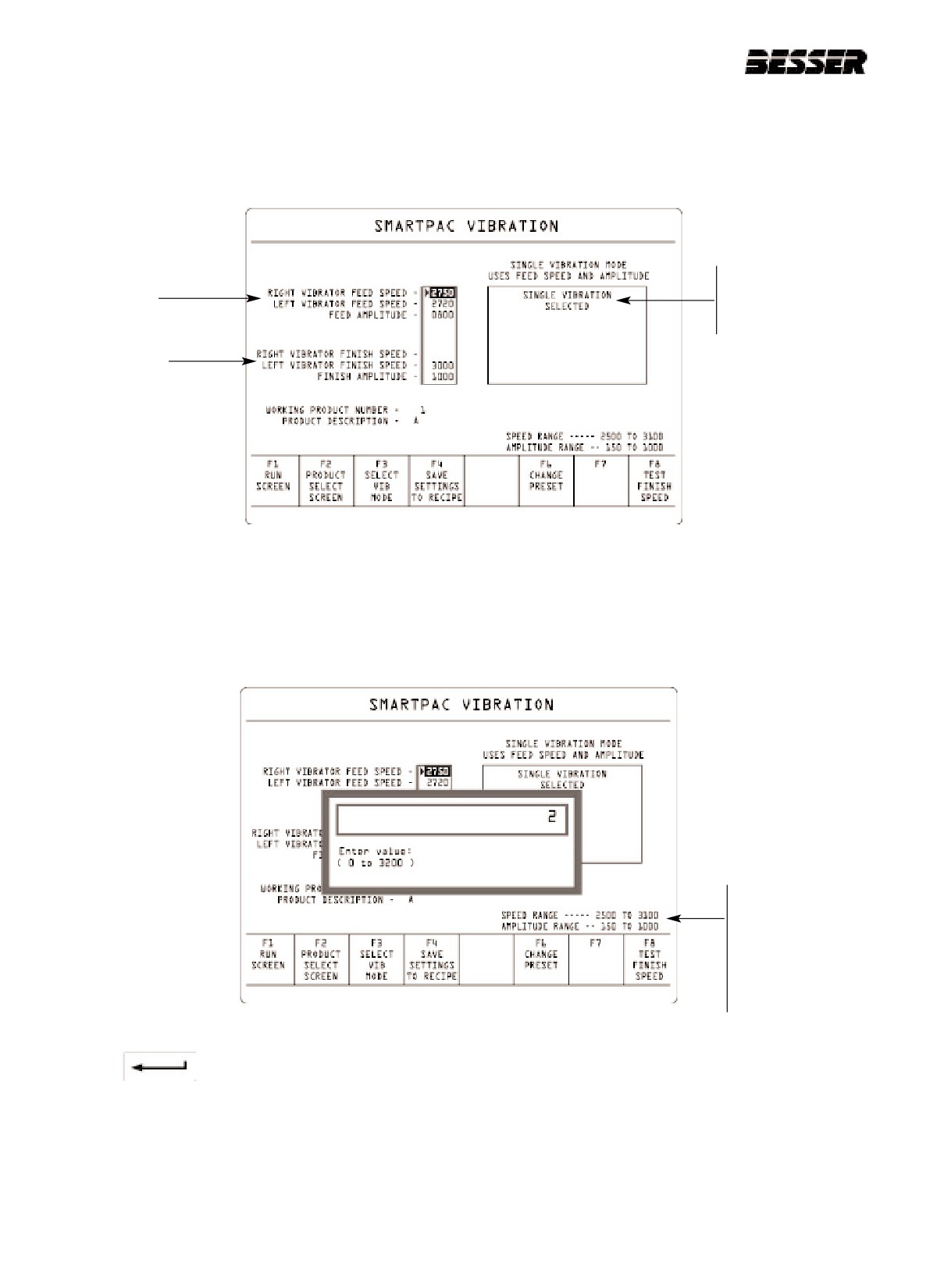
This menu allows the operator to enter desired vibrator speed and amplitude for the SMARTPAC vibrating system.
The operator can also access some other data such as speed and amplitude range.
To access this screen from the RUN SCREEN, press F4. (SMARTPAC VIBRATION)
In this case, the
Single vibration
Single vibration
mode has been
selected.
Double vibration
9.12.1 TO CHANGE VIBRATION PRESET VALUES:
1. Press the F3 key to select a vibration mode. The screen above shows an example where the operator has
selected the Single vibration mode. To change the Smartpac preset value, press the F6 key.
The display will read:
Speed and amplitude
ranges:
If values is not within
these values, the
message "value out of
range" will appear on
screen.
2. Enter the new preset value (from 0 to 3200)
3. Press the
key.
9-32
466361F9710US F1 29OC99
SECTION 10
TROUBLESHOOTING
SECTION 10
TROUBLESHOOTING
THIS SECTION WILL HELP YOU SOLVE TWO KINDS OF PROBLEMS:
1. Problems with machine. Those problems are diagnosed by the Small Logic Controller (see section 9)
and will show up on the screen as outlined in section 10.1 below.
2. Problems with the concrete units. Those problems are diagnosed by looking at the concrete units as
outlined in section 10.2.
10.1
SMALL LOGIC CONTROLLER FAULTS.
10.1.1 WHEN A MECHANICAL FAULT OCCURS, THE MACHINE STOPS AND THE FAULT SHOWS ON
THE SCREEN. WHEN THIS HAPPENS:
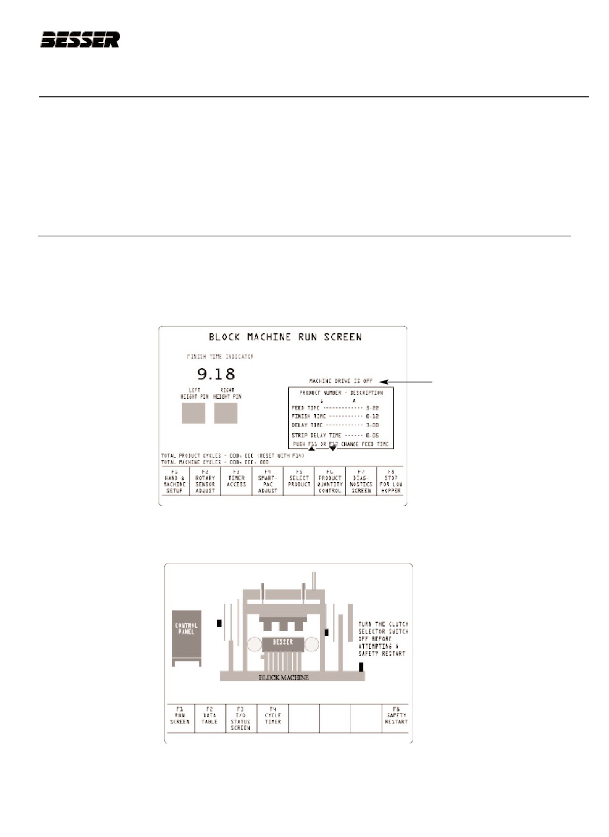
1. The display on your Graphic Control Unit will read:
Screen indicates that
there is a fault in the
machine.
2. Press F7 to inquire about the fault (diagnostic).
The display will read:
This screen shows a diagram of the machine and indicates where the fault is located.
10-1
466361F9710US F1 29OC99
SECTION 10
TROUBLESHOOTING
3. Correct the fault.
Once the fault has been corrected:
4. Turn the clutch selector switch to "OFF".
5. Press the F9 key.
6. Turn clutch switch "ON".
The machine will sound an alarm and restart.
10.1.2 LIST OF CONCRETE PRODUCTS MACHINE FAULTS
1.
THE VIBRATOR, AGITATOR, AUTOFEED OR PALLET CLEANER MCP OR OVERLOAD IS TRIPPED.
The vibrator, agitator, autofeed or pallet cleaner motor circuit protector (MCP) or overload is tripped. This error
may indicate:
- Motor is not rotating freely. Verify motor rotation.
- Motor has an electrical short in its winding. Check resistance of winding.
- Wiring to the motor is shorted. Verify continuity of wiring to motor.
2.
THE MAIN DRIVE MCP OR OVERLOAD IS TRIPPED.
The main drive motor circuit protector (MCP) or overload is tripped. This error may indicate:
- Motor is not rotating freely. Verify motor rotation.
- Motor has an electrical short in its winding. Check resistance of winding.
- Wiring to the motor is shorted. Verify continuity of wiring to motor.
3.
THE BLOCK MOVING BAR DRIVE MCP OR OVERLOAD IS TRIPPED.
The block moving bar motor circuit protector (MCP) or overload is tripped. This error may indicate:
- Motor is not rotating freely. Verify motor rotation.
- Motor has an electrical short in its winding. Check resistance of winding.
- Wiring to the motor is shorted. Verify continuity of wiring to motor.
4.
THE SYSTEMS AIR PRESSURE IS LOW.
The system air pressure switch PS-13 indicates low pressure.
- Insure the air compressor is working properly.
- Check for proper connection of air lines.
5.
THE LUBE RESERVOIR IS LOW.
The lube level switch LS-11 indicate that the grease reservoir is low.
- Refill grease reservoir as required (see section 11).
10-2
466361F9710US F1 29OC99
SECTION 10
TROUBLESHOOTING
6. MACHINE ROTATION IS UNDER SPEED.
This condition can be caused by a motor or clutch deficiency. An object jammed in the machine can also cause
this fault. If pallet jams the machine, the shear bolt on the timing sprocket will break to avoid further damage to
the machine.
7. ROTARY SENSOR IS OUT OF SYNC.
The rotary sensor coupling has slipped. Adjust the rotary sensor to 100 degrees at 1st stop and tighten coupling
clamps.
8. THE MATERIAL HOPPER IS LOW.
The material hopper is low of material and will not allow the machine to operate until additional concrete is deliv-
ered to the hopper. This condition may be bypassed by use of the "F8" key on the Run screen.
9. THE MAIN DRIVE BESCODYNE IS OVER NORMAL TEMPERATURE.
The temperature sensor on the main drive bescodyne has tripped.
- Check oil level of bescodyne drive to insure it is properly filled.
- Replace oil as required (see section 11).
10. A VIBRATOR BESCODYNE IS OVER NORMAL TEMPERATURE.
The temperature sensor on the main drive bescodyne has tripped.
- Check oil level of bescodyne drive to insure it is properly filled.
- Replace oil as required (see section 11).
11. THE HEAD IS NOT PROPERLY CLAMPED (only on machine with Mold Head Clamp Device).
The mold head clamp device is not in the "UP" and "LOCKED" position.
- Insure sensor head "UP" sensor (PRS-16) is tripped. If it has not, raise head with use of the graphic display sta-
tion.
- Insure sensor head "LOCK" sensors (PRS-12 and PRS-13) are tripped. If not, lock the head with use of the
graphic display station.
12. THE PALLET MAGAZINE IS LOW.
The pallet magazine is low. The concrete units machine will not operate until pallets are provided to the maga-
zine.
13. A PALLET SKIP ERROR HAS OCCURRED.
A pallet was not present on the Pallet Skip switch PRS-3 when the height pins met.
- Check to insure pallets are moving freely through machine.
10-3
466361F9710US F1 29OC99
SECTION 10
TROUBLESHOOTING
14. A PALLET HAS BEEN ON LS-2A TOO LONG.
A pallet is stopped over LS-2A on the front delivery conveyor too long.
- Check to insure the front delivery conveyor is running, if not restart conveyor.
- Check to insure pallets are moving freely on the front delivery conveyor
15. THE MACHINE IS AT THIRD STOP TOO LONG. MAY HAVE MISSED LS-7.
The machine is waiting at third stop too long and waiting for the block moving bars to travel forward.
16. THE MACHINE HAS CYCLED TOO MANY TIMES WITHOUT A LUBE CYCLE.
The lube cycle switch LS-11 has not toggled on or off within a preset amount of machine cycles (Counter C5:0).
- Check for blocked grease lines.
- Check to insure the lube pump is working properly.
- Increase lube pump cycle rate by decreasing the preset of lube pump timer (T4:5).
10-4
466361F9710US F1 29OC99
SECTION 10
TROUBLESHOOTING
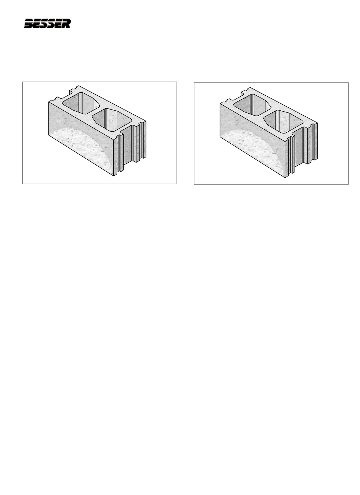
10.2 SOLUTIONS TO CORRECT DEFORMED AND CRACKED BLOCKS.
10.2.1 CRACKED FACE SHELLS
10.2.2 HALF-MOON ON FACE SHELL
a.
Check mold to stripper head alignment (section 5).
a.
Check for loose division plates.
b.
Check to see if core assembly is bent or twisted
b.
Check pallet receiver rubbers.
due to over tightening.
c.
Check that pallet is moving on the conveyor.
c.
Check mix (moisture content). An inconsistent
moisture content in your mix may result in inconsis-
d.
Check vibrator bearings.
tent concrete product quality. The use of a comput-
erized moisture control unit in you mixer is recom-
e.
Check pallet receiver rubbers (hardness).
mended to improved product quality and consisten-
cy.
f.
Check mold assembly.
d.
Check pallet receiver guides on slide shaft (section
g.
Check amount of admix in concrete.
5).
g.
Increase delay time (section 9).
h.
Check shock absorbers.
I.
Check pallet receiver rubbers.
J.
Check admix.
k.
Check amount of material being left in mold after
feedbox goes back.
10-5
466361F9710US F1 29OC99
SECTION 10
TROUBLESHOOTING
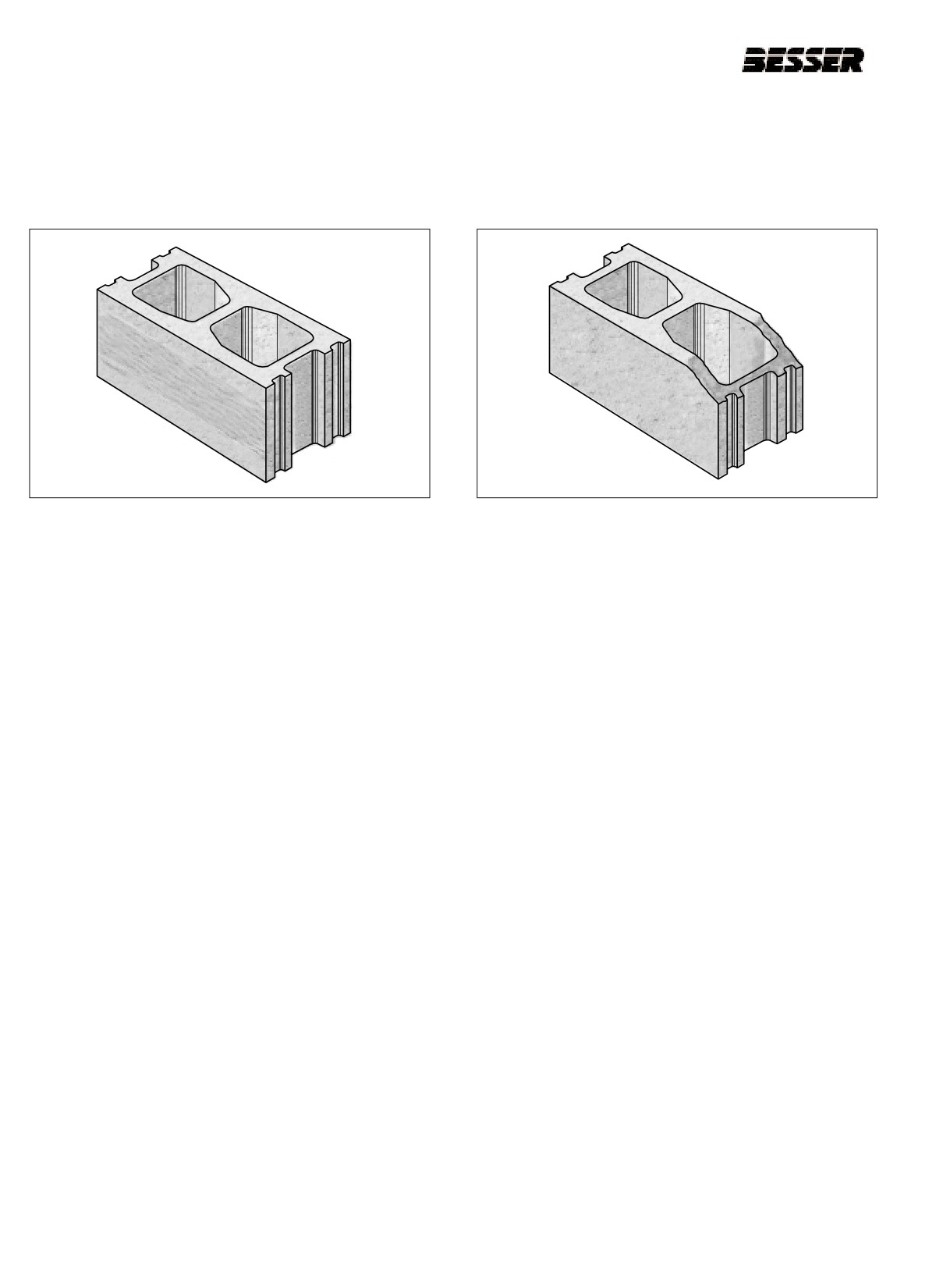
10.2.3 LAMINATION ON FACE SHELL AND
10.2.4 FRONT OF BLOCK NOT FILLED
HORIZONTAL CRACKING
a. Check vibrator shaft speeds for R.P.M. (they
a. Check hopper gate setting.
should turn within 2 R.P.M. of each other - adjust
with screw.
b. Check feedbox travel forward.
b. Check for metal to metal contact during vibration
c. Check agitator.
(mold vibrating against machine mold throat).
d. Check for chunks in feedbox.
c. Check back apron plate alignment to mold
(section 5)
e. Mix may be too wet.
d. Check that Feedbox is not vibrating on mold.
f.
Check feed time. Increase if necessary. (section 8
and 9)
e. Check vibrator bearings.
f.
Check delay time (decrease or increase).
(section 9)
g. Check mix design.
h. Check for loose division plates.
i.
Check for lack of proper admix.
j.
Check slide shaft pucks (section 5).
10-6
466361F9710US F1 29OC99
SECTION 10
TROUBLESHOOTING
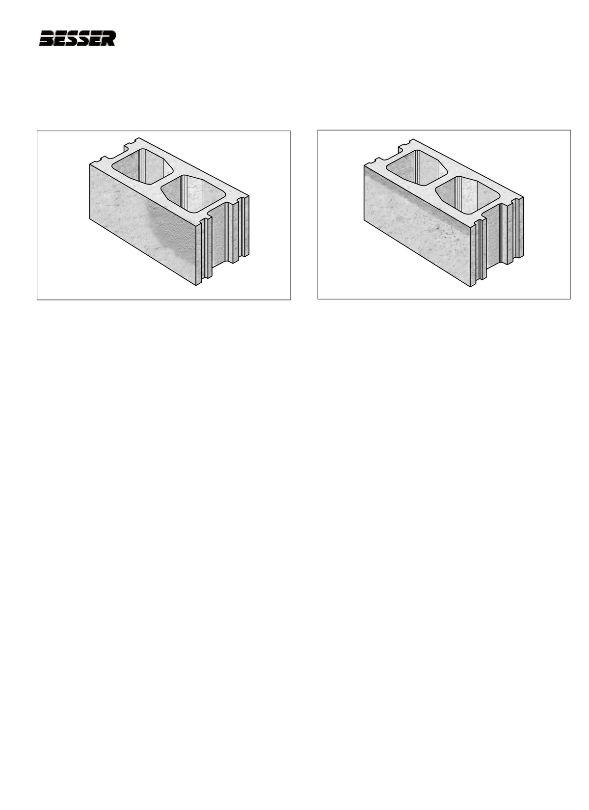
10.2.5 AREA OF FACE SHELL TOO COARSE
10.2.6 SMOOTH TOP EDGE ON FACE SHELL
a. Check machine hopper for build up.
a.
Check for division plate wear.
b. Make sure vibrator sheaves are properly aligned.
b.
Make sure stripper shoes protrude through bottom
of mold at completion of stripping.
c. Check vibrator weights for proper balance (equal
length of clamping bolts and equal weight of nuts).
c.
Check stripper head alignment. (section 5)
d. Check for loose mold parts.
d.
Check for loose stripper shoes.
e. Check for material segregation.
e.
Check pallet receiver frame for level. (section 5)
f.
Check vibrator shaft speed.
f.
Check moisture content of mix.
g. Check finish times. (sections 8 and 9)
h. Check feed time. Decrease if necessary.
(sections 8 and 9)
i.
Check autofeed mechanism. Lower if necessary.
10-7
466361F9710US F1 29OC99