BESSER DYNAPAC 3 AT A TIME (466361F9710US). OPERATION / MAINTENANCE MANUAL - page 3
SECTION 5
MOLD INSTALLATION
B. Placing mold and stripper head in machine
without the use of the optional Mold insertion
device.
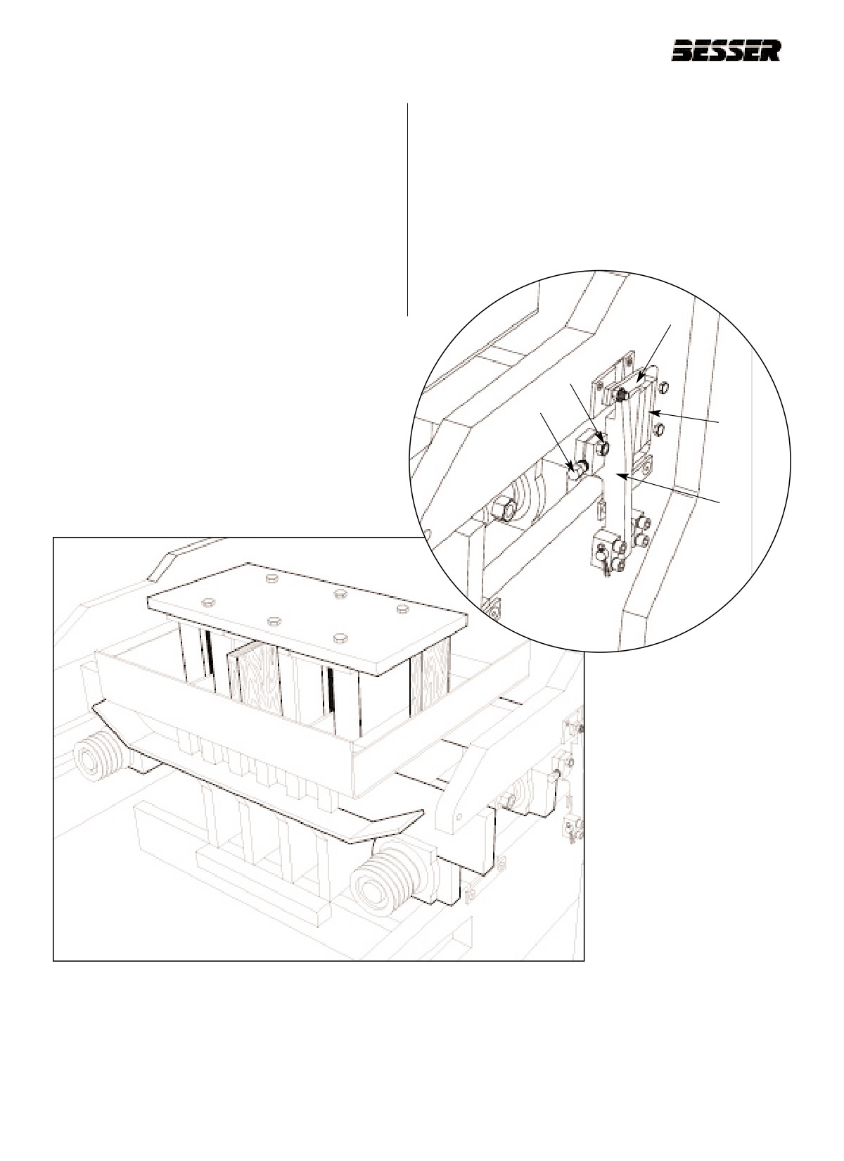
5.4.11 Place mold and stripper head in machine (see
5.4.14 Tighten the bolt (D) hand tight and then back off
figure 5.13), back against mold throat liners (E)
1/4 of a turn (see figure 5.13b).
(see figure 5.13b).
5.4.15 Tighten the clamp bolt (C) (see figure 5.13b).
5.4.12 Close mold locks (A) and latch (B) (see figure
5.13b).
5.4.13 Loosen the clamp bolt (C) (see figure 5.13b).
B
C
D
Figure 5.13b SECURING THE MOLD.
E
A
Figure 5.13
PLACING MOLD AND STRIPPER HEAD IN MACHINE.
NOTE: This figure has been simplified for illustration
purposes.
5-10
466361F9710US F1 29OC99
SECTION 5
MOLD INSTALLATION
5.4.16
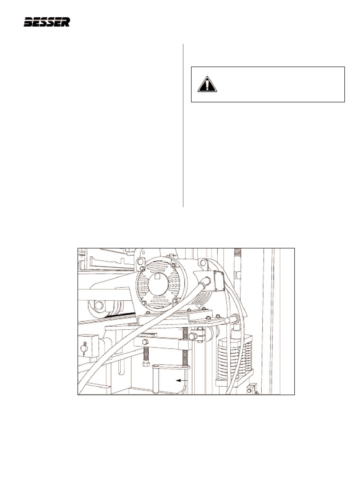
Raise both vibrator motors with screw jacks (C)
5.4.21 Disconnect safety chain, and hang it on chain
(see figure 5.14). Screw vibrators jacks up and
hook.
place V-belts from vibrating motor sheaves to
vibrating shaft sheaves. On a standard vibra-
WARNING: Do not raise the stripper
tion system, you must install 4 belts on each
head frame too high; otherwise the feed-
side. On a Smartpac system, you must install 2
box will come forward resulting in crush
belts on each side.
hazard!
5.4.17
Lower right hand vibrator motor, then left hand
vibrator motor to tighten belts. Make sure
5.4.22 Turn power back on. Do not start main drive
sheaves are aligned. Lower jack screws to cot-
motor. Turn clutch switch to the “Jog” position
ter pins.
and push the “Jog” button to allow the stripper
head frame to lower to the top of stripper head
5.4.18
Make sure no one is standing on or near
plate.
machine and turn power back on. Hit MCR reset
button and start main drive motor.
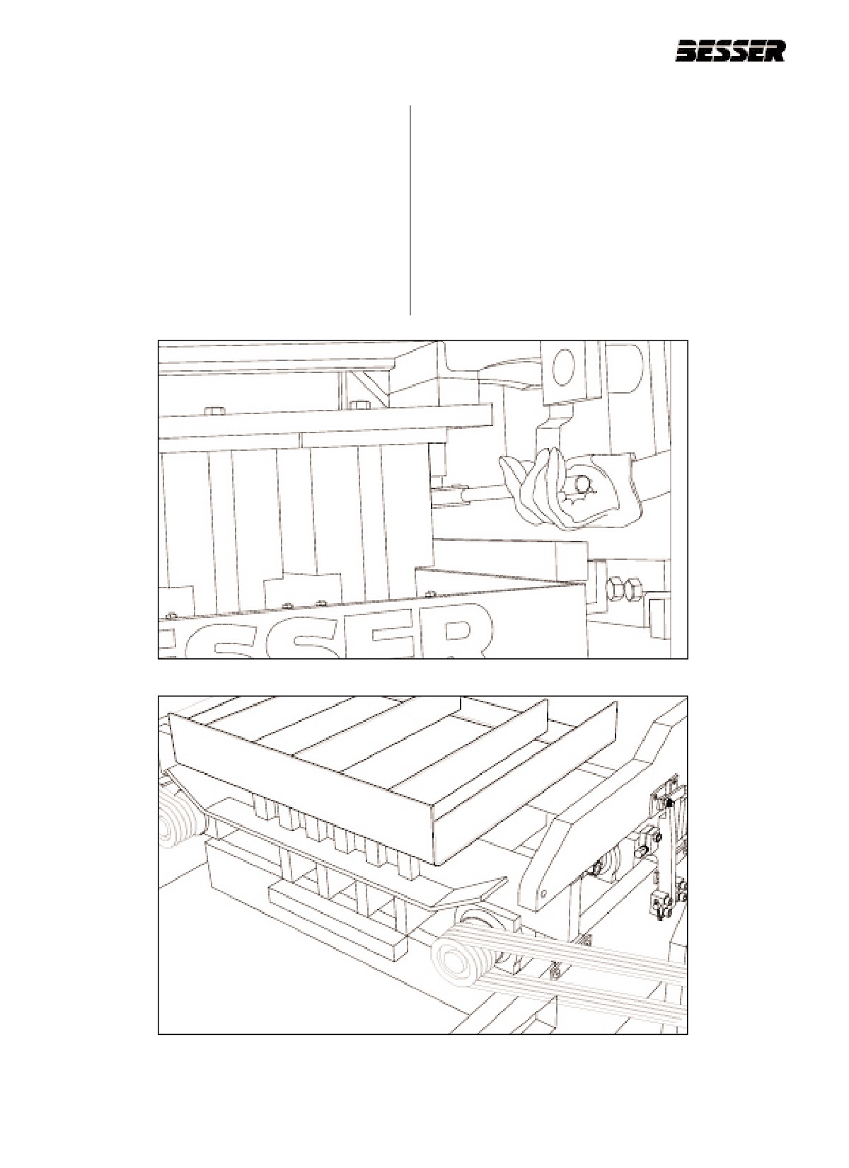
5.4.23 Bolt stripper head plate to stripper head frame.
Do not tighten bolts completely. Tighten until
5.4.19
Jog machine to raise the stripper head frame
head plate contacts the stripper head frame
just high enough to disconnect safety chain.
(see figure 5.15).
5.4.20
Shut off clutch and turn power off. Wait until
5.4.24 Place a good pallet on the pallet receiver rub-
motor has stopped completely. Also, lock out
bers.
machine.
C
Figure 5.14
RAISING THE VIBRATOR MOTORS WITH SCREW JACK (C).
466361F9710US F1 29OC99
5-11
SECTION 5
MOLD INSTALLATION
5.4.25 Start main drive motor. Jog machine to raise
machine and turn power back on. Hit MCR reset
stripper head just high enough to remove 2"x4"
button.
blocking from under stripper head plate.
5.4.29 Cycle machine to “first stop” position (feedbox
5.4.26 Shut off clutch and turn power off. Wait until
all the way to the front), turn clutch switch off
motor has stopped completely. Also, lock out
and stop drive motor. At this point the mold and
machine.
pallet should be on the pallet receiver rubbers
(see figure 5.16).
5.4.27 Remove the rear blocks first, then remove the
front block.
5.4.28 Make sure no one is standing on or near
Figure 5.15
BOLT STRIPPER HEAD PLATE TO STRIPPER HEAD FRAME.
Figure 5.16
MOLD RESTING ON THE PALLET RECEIVER.
5-12
466361F9710US F1 29OC99
SECTION 5
MOLD INSTALLATION
5.5
ADJUSTING THE MOLD
A. Levelling the mold
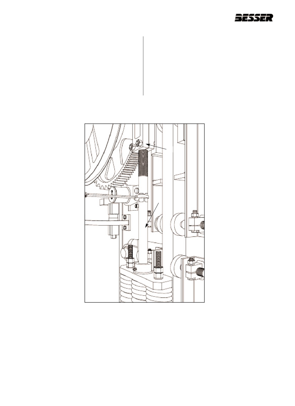
5.5.4
If the dimension on each side is not approxi-
5.5.1
Run machine to “first stop” (feedbox all the way
mately 5/8" [16mm], adjustment must be made
forward) (see figure 5.1).
using the pallet receiver link rods (B) (see figure
5.18, next page), after loosening nut (A) (see
5.5.2
Shut off clutch and turn power off. Wait until
figure 5.18).
motor has stopped completely. Also, lock out
machine.
5.5.5
Turn power back on and vibrate mold.
5.5.3
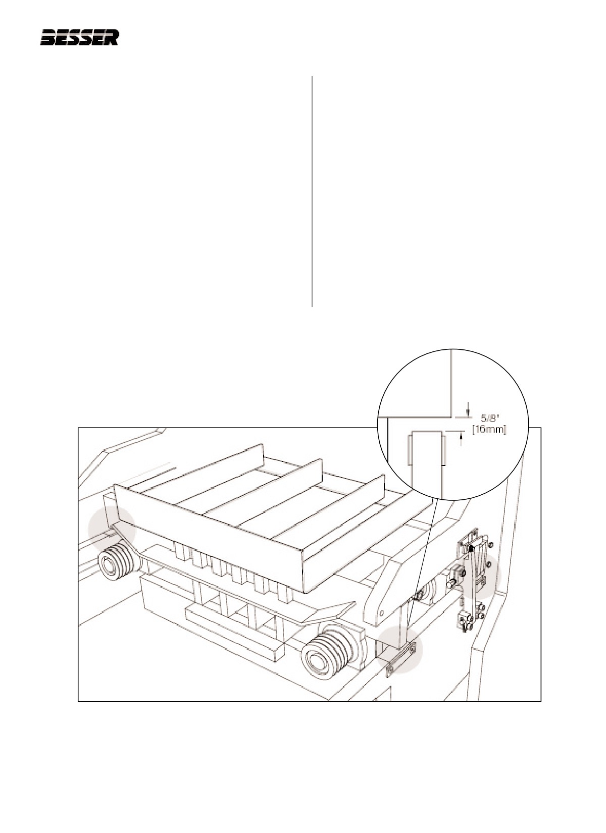
Check level of mold from side to side and from
5.5.6
Shut off clutch and turn power off. Wait until
front to back until bottoms of mold side bars are
motor has stopped completely. Also, lock out
approximately 5/8” [16mm] above mold throat
machine.
plates at all four check points (see figure 5.17).
5.5.7
Check level of mold from side to side and from
front to back until bottoms of mold side bars are
5/8” [16mm] above mold throat plates at all four
check points (see figure 5.17).
Figure 5.17
SIDE TO SIDE DIMENSION (3 of the 4 check points shown).
466361F9710US F1 29OC99
5-13
SECTION 5
MOLD INSTALLATION
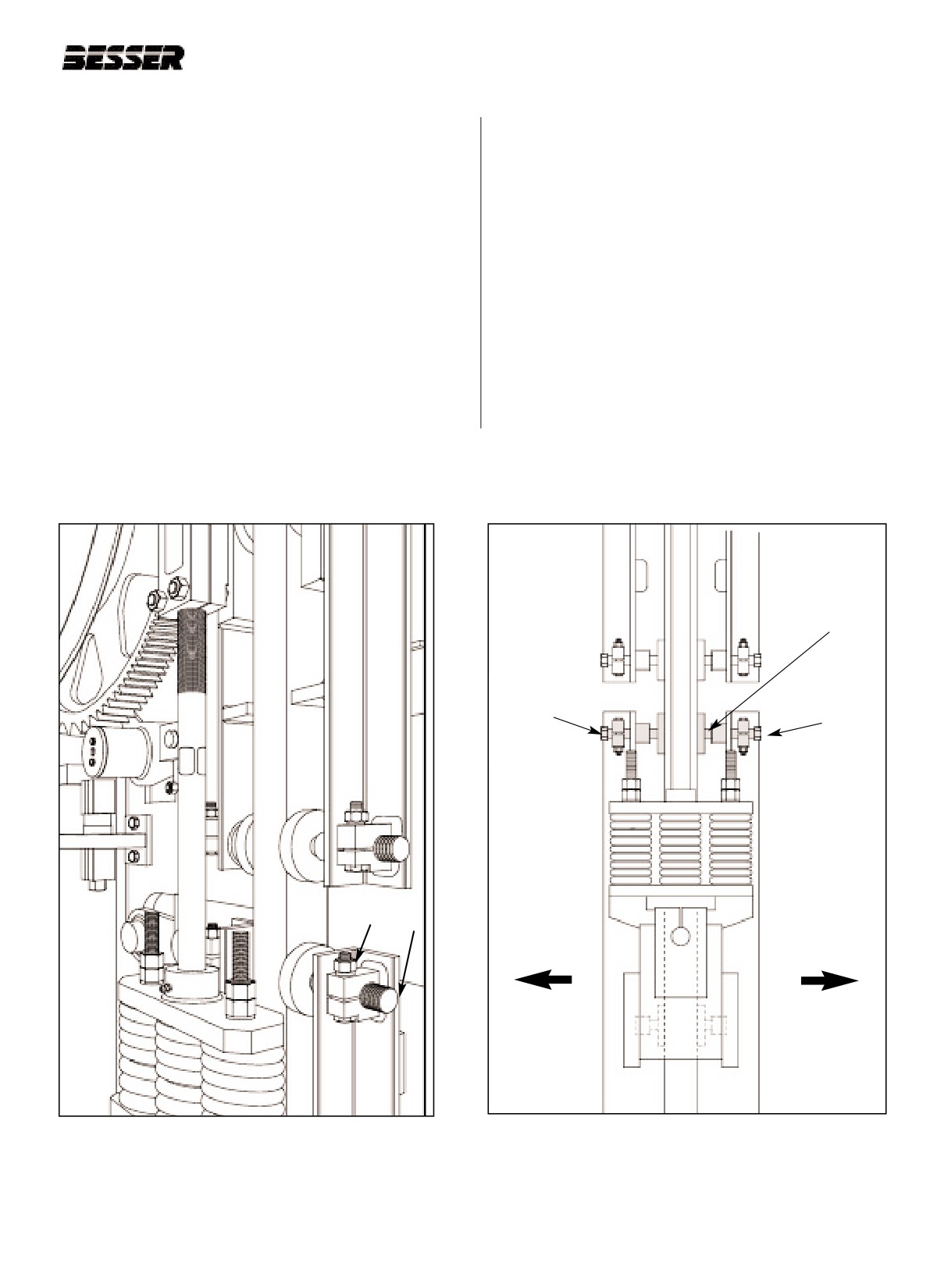
5.5.8
If the dimension on each side is not
5.5.11 Recheck level of mold and adjust following
5/8" [16mm], adjustment must be made using
steps 5.5.3 to 5.5.5 until mold is perfectly lev-
the pallet receiver link rods (B) (see figure 5.18),
elled. Tighten nut (A) (see figure 5.18).
after loosening nut (A) (see figure 5.18).
5.5.9
Turn power back on and vibrate mold again.
5.5.10 Shut off clutch and turn power off. Wait until
motor has stopped completely. Also, lock out
machine.
A
B
Figure 5.18
PALLET RECEIVER LINK
ROD (LEFT SIDE SHOWN).
5-14
466361F9710US F1 29OC99
SECTION 5
MOLD INSTALLATION
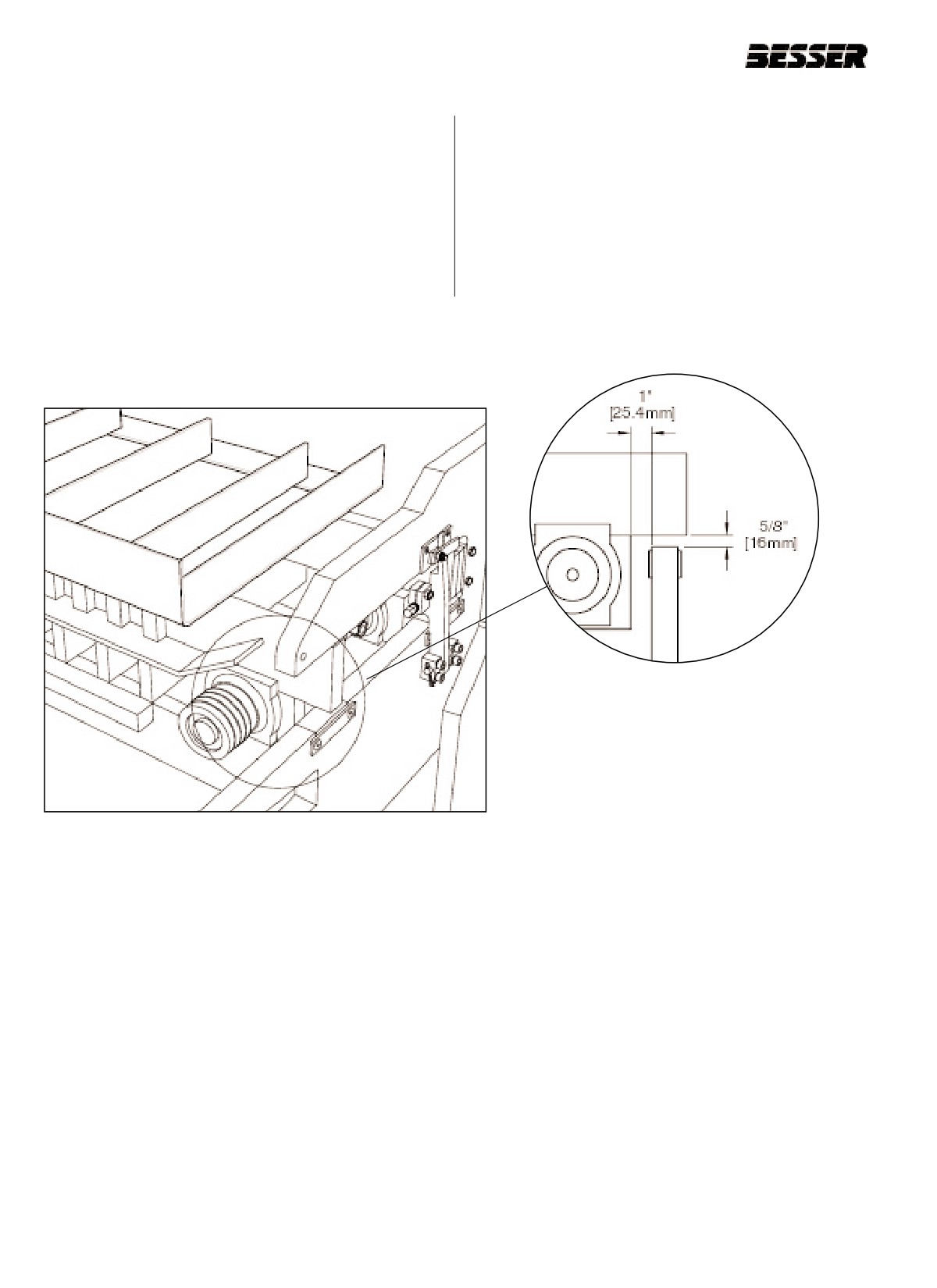
5.5.12 If the dimension in front and back is not 5/8"
5.5.13 Make adjustments on right hand side by backing
[16mm], carry out adjustment by first checking
one guide liner away from slide shaft and tight-
clearance of bottom guide liners on both sides
ening the other against the slide shaft. To raise
of the machine. If clearance is off, tighten front
the front, loosen the front and tighten the back.
screw hand tight and then back off 1/4 of a turn
To raise the back, loose the back and tighten
balancing out both guide liner adjusting screws.
the front. See figure 5.20 below.
These screws are located at the bottom of the
pallet receiver frame at the slide shaft on both
5.5.14 After 5/8” [16mm] adjustment is obtained, go
sides of the machine.
back to the left hand side of the machine and
retighten loosened guideliner adjusting screws.
a. To make the following adjustments (see figure 5.19):
Then back rear screw 1/4 of a turn so this guide
liner will move freely.
1. Loosen the nut (A).
2. Adjust the guide liner (B) as desired.
5.5.15 Vibrate between each adjustment. Turn clutch
3. Tighten the nut (A).
off and power off before checking dimensions
and/or making adjustments.
GUIDE
LINER
TIGHTEN
TIGHTEN
BACK TO
FRONT TO
RAISE
RAISE
FRONT
BACK
A
B
BACK OF
FRONT OF
MACHINE
MACHINE
Figure 5.19
UPPER GUIDE LINER
Figure 5.20
PALLET RECEIVER FRAME ADJUSTMENT.
ADJUSTMENT SCREW.
466361F9710US F1 29OC99
5-15
SECTION 5
MOLD INSTALLATION
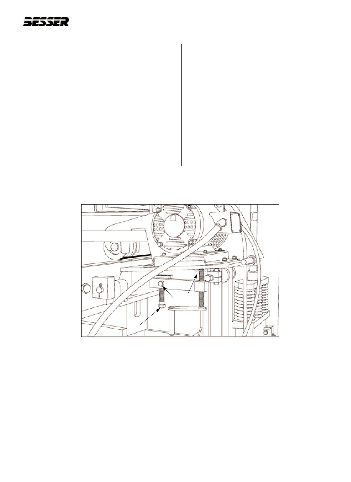
B. Mold lateral adjustment.
machine.
5.5.18 Check for centered position in machine. Mold is
Note: The mold and pallet are supported by the pallet
centered when mold side bars are approximate-
receiver frame.
ly 1” [25.4mm] between vibrator bearing blocks
and the inside of mold throat plates (see figures
5.5.16 Vibrate mold.
5.21 and 5.22).
5.5.17 Shut off clutch and turn power off. Wait until
Note: The 1” [25.4mm] wide gooseneck pry bar (part
motor has stopped completely. Also, lock out
#61397) works nicely for mold centering.
Figure 5.22 USING THE 1" [25.4mm]
DIMENSION TO CENTER
THE MOLD.
Figure 5.21
CENTERING THE MOLD.
Note: This figure has been simplified for illustration
purposes.
5-16
466361F9710US F1 29OC99
SECTION 5
MOLD INSTALLATION
5.5.19 Loosen clamp bolt (A) (see figure 5.23).
5.5.24 Recheck 1” dimension. During vibration, if mold
works off center to the right, turn adjusting
5.5.20 Turn adjusting screw (B) up until it contacts
screw (B) up (see figure 5.23) which will move
under side of right hand vibrating motor support
the vibrating motor up. If molds works off center
plate (see figure 5.23). The adjusting screw (B)
to the left, turn adjusting screw (B) down (see
is located under the right vibrating motor.
figure 5.23).
5.5.21 Turn power back on. Hit MCR reset button.
Note: Make sure base is not on the jacking screw (C)
when adjusting vibrating motor height (see figure
5.5.22 Vibrate mold.
5.23).
5.5.23 Shut off clutch and turn power off. Wait until
5.5.25 Repeat step 5.5.24 if necessary, until mold
motor has stopped completely. Also, lock out
automatically remains centered. No adjustment
machine.
is required on left hand vibrating motor. Equal
belt tension is automatically maintained.
5.5.26 Tighten clamp bolt (A).
A C
B
Figure 5.23
VIBRATING MOTOR HEIGHT ADJUSTMENT SCREW (B).
466361F9710US F1 29OC99
5-17
SECTION 5
MOLD INSTALLATION
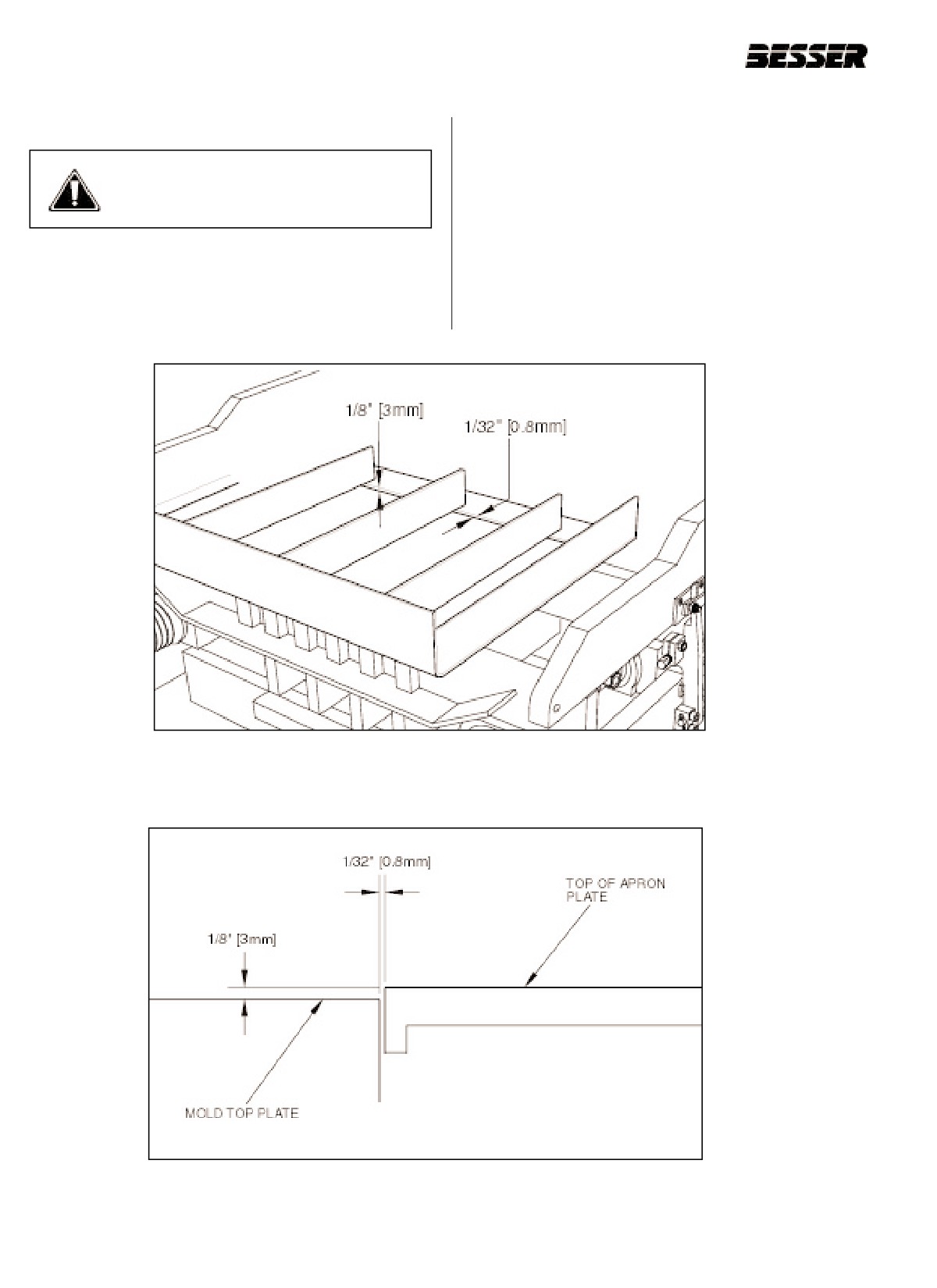
5.6 APRON PLATE ADJUSTMENT
Note:
1/8" [3mm] is a good reference provided the
feedbox does not contact the mold during vibra-
WARNING: The following procedure
tion.
must be done with power off and
machine locked-out!
5.6.2
Check to see that there is approximately 1/32"
[0.8mm] clearance between the apron plate and
the back of the mold top plate (see figure 5.24
5.6.1
Adjust so the apron plate is 1/8" [3mm] above
and 5.25).
the mold top plate (figure 5.25) with the machine
at “first stop”.
5.6.3
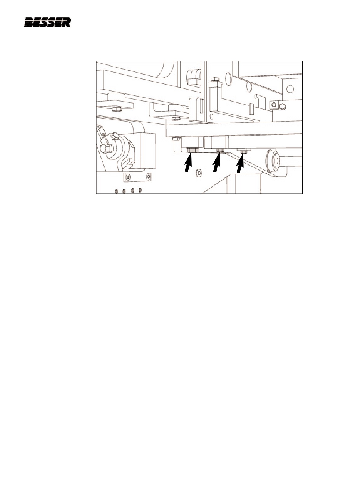
If necessary, adjust apron plate. Loosen bolts
and move forward or back (see figure 5.26).
Figure 5.24
APRON PLATE CLEARANCE.
Figure 5.25
APRON PLATE CLEARANCE.
5-18
466361F9710US F1 29OC99
SECTION 5
MOLD INSTALLATION
Figure 5.26
APRON PLATE ADJUSTMENT (FORWARD TO BACK).
466361F9710US F1 29OC99
5-19
SECTION 5
MOLD INSTALLATION
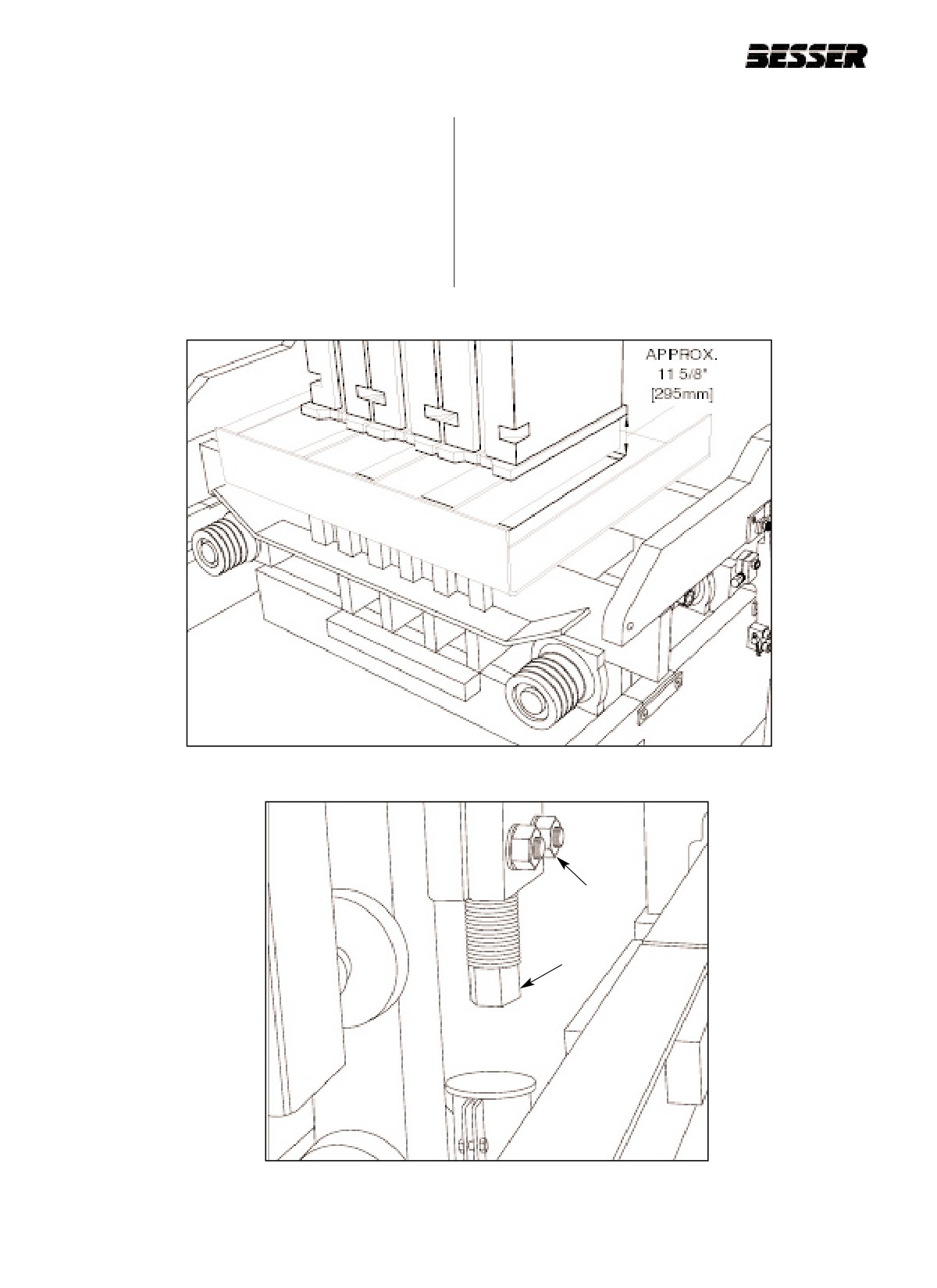
5.6.4
Run machine to “first stop” (feed box all the way
5.6.6
Measure from bottom of shoe to top of mold end
forward). See figure 5.1.
liners (see figure 5.27). Add dimension “C” to this
measurement (dimension “C” is the amount of
5.6.5
Shut off clutch and turn power off. Wait until
compression. For detailed explanations, see sec-
motor has stopped completely. Also, lock out
tion 5.8)
machine.
5.6.7
Loosen nuts (A) and set height pins (B) to be this
far away - the final result of the measurement in
5.5.6 - from lower height stops (figure 5.28).
Figure 5.27 SHOES 4" [102MM] ABOVE MOLD.
A
B
Figure 5.28
HEIGHT PINS ADJUSTMENT (LEFT SIDE SHOWN).
5-20
466361F9710US F1 29OC99
SECTION 5
MOLD INSTALLATION
5.7
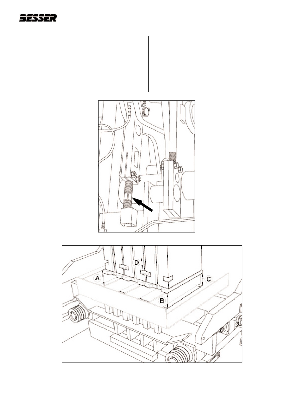
ADJUSTING STRIPPER HEAD
5.7.3
If the head is not levelled side to side (A to B)
5.7.1
Run machine to “first stop” (feed box all the way
(see figure 5.30), adjust the left hand stripper
forward). See figure 5.1.
head adjusting link (see figure 5.29).
5.7.2
To determine if the head is level with mold (left to
right and front to back), measure how far the
bottom of the stripper shoes are above the mold
end liners at all 4 corners (A, B, C and D) (see
figure 5.30).
Figure 5.29
L.H. STRIPPER HEAD LINK.
Figure 5.30
STRIPPER SHOES POSITION.
466361F9710US F1 29OC99
5-21
SECTION 5
MOLD INSTALLATION
5.7.4
If the stripper head is not level (B to C) (see fig-
5.7.5
Make adjustment on the right hand side by
ure 5.30) with the mold from front to back, back
backing one lower stripper head guide liner
out both lower guide liner adjusting screws on
away from the slide shaft and tightening the
the stripper head frame at the slide shaft on the
other against the slide shaft. To raise the front,
left hand side of machine (see figure 5.31).
loosen rear and tighten front. To raise the back,
Loosen nut (A) and adjust with bolt (B).
loosen the front and tighten the rear (see figure
5.32).
GUIDE
LINER
TIGHTEN
TIGHTEN
BACK TO
FRONT TO
RAISE
RAISE
BACK
FRONT
A
BACK OF
FRONT OF
B
MACHINE
MACHINE
Figure 5.31
LOWER GUIDE LINER ADJUSTMENT
Figure 5.32
STRIPPER HEAD FRAME
SCREW.
ADJUSTMENT.
5-22
466361F9710US F1 29OC99
SECTION 5
MOLD INSTALLATION
5.7.6
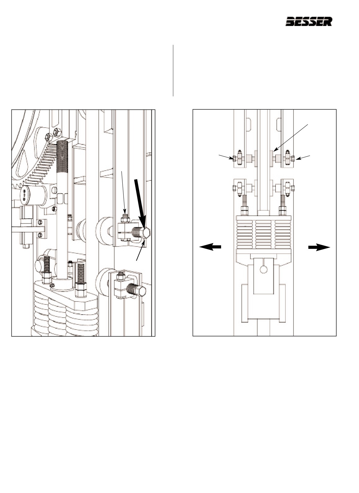
After head is level with mold, tighten both
5.7.10 Adjust bottom of shock absorbers to pads to
adjustment screws against the slide shaft on the
dimension of unit height plus 3/4" [19mm].
left hand side (see figure 5.31). Then loosen the
front adjustment screws 1/4 of a turn and tighten
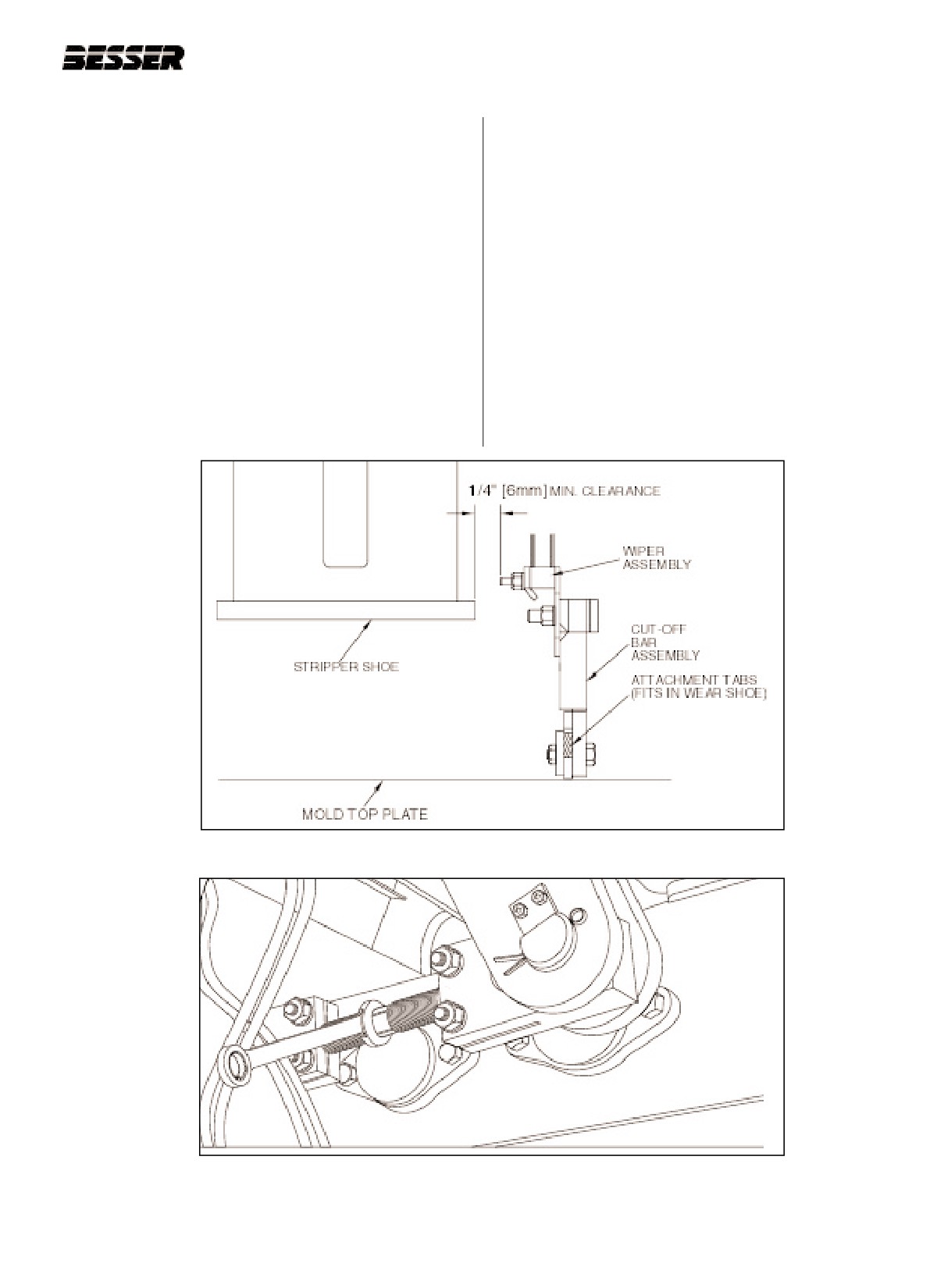
5.7.11 Put in agitator grid and cut-off bar, and check
clamp bolts.
feedbox alignment. There should be a minimum
clearance of 1/4" [6mm] between the wiper
5.7.7
Turn power back on. Hit MCR reset button.
assembly and the stripper shoe as shown in fig-
ure 5.33.
5.7.8
Turn height pins OFF. Jog machine to “second
stop” (Ref. section 7.3). Stripper shoes should
Note: For units higher than 3 5/8”, clearance with
be in mold and height pins should touch.
stripper head plate must also be maintained.
5.7.9
Shut off clutch and turn power off. Wait until
5.7.12 If adjustment is necessary, adjust the feedbox
motor has stopped completely. Also, lock out
linkages (see figure 5.34).
machine.
Figure 5.33
FEEDBOX ADJUSTMENT.
Figure 5.34
FEEDBOX LINKAGE.
466361F9710US F1 29OC99
5-23
SECTION 5
MOLD INSTALLATION
5.7.13 Turn power back on. Hit MCR reset button.
5.7.17 Shut off clutch and turn power off. Wait until
motor has stopped completely. Also, lock out
5.7.14 Make sure that machine is at “second stop”
machine.
(Ref. section 7.3).
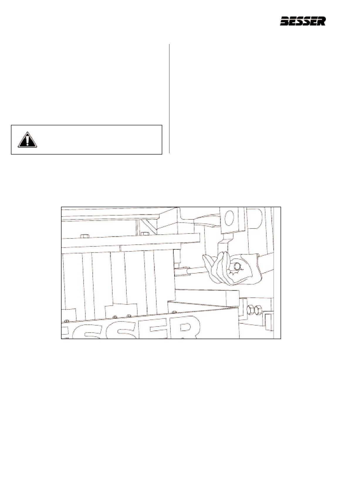
5.7.18 Tighten the head bolts (figure 5.35).
5.7.15 Shut off clutch.
5.7.19 Turn height pins ON.
5.7.16 Turn vibrator switch to "hand" position for 5 sec-
onds.
WARNING: Make sure guards are in
place over vibrator belts!
Figure 5.35
TIGHTENING THE HEAD BOLTS.
5-24
466361F9710US F1 29OC99
SECTION 5
MOLD INSTALLATION
5.8
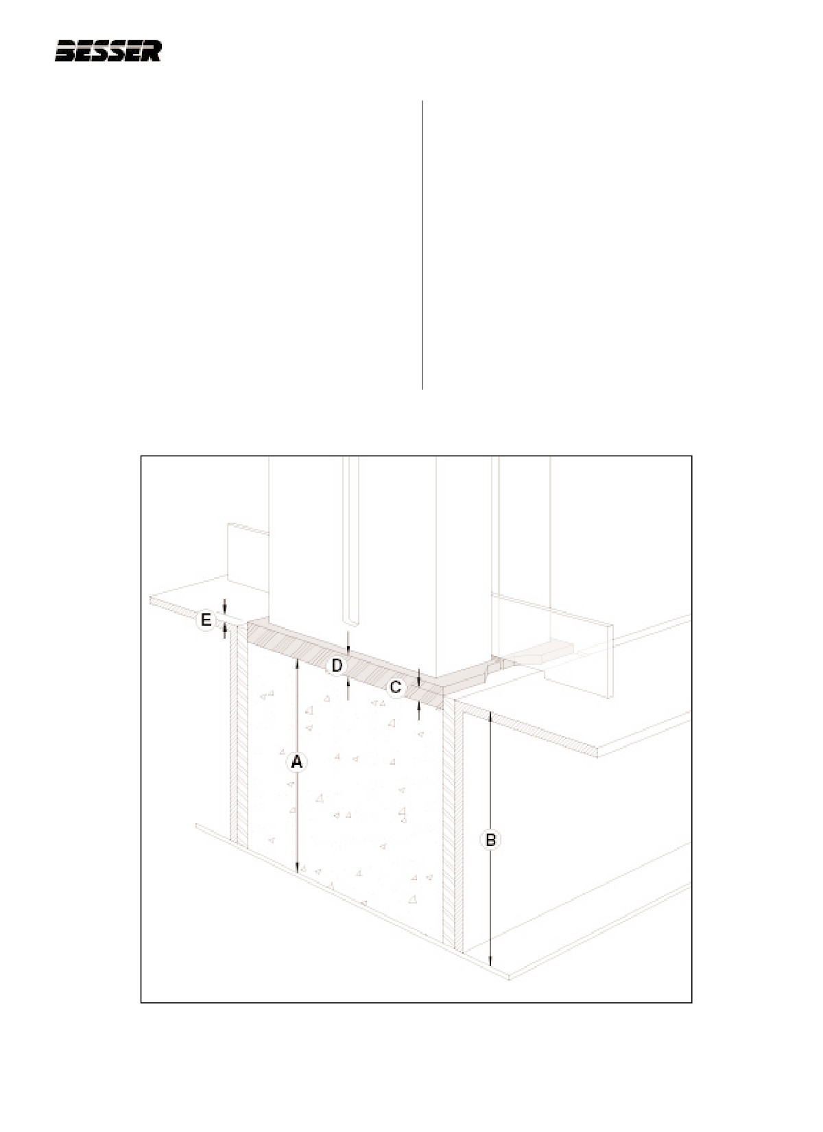
COMPRESSION CALCULATION
Letter E is the height of the stripper shoes above
end liners (letter C is the amount of compres-
5.8.1 To correctly evaluate the amount of compression
sion).
needed from the stripper head to make units of
the desired height, the operator must use the fol-
EX: Suppose the operator wants to make
lowing equation:
7 5/8" [194mm] high units in a 8 1/4" [209mm]
high mold with stripper shoes of 1 1/2" [38mm]
SAL = UH - MH + ST
thickness. The operator gets a result of
7/8" [23mm] for the height of stripper shoes
In this equation, UH represents Unit Height, MH is
above end liners:
Mold Height and SST is Stripper Shoes
Thickness. The result, SAL, is the height of the
7 5/8" - 8 1/4" + 1 1/2" = 7/8"
stripper Shoes Above end Liners.
Or, in millimiters:
194mm - 209mm + 38mm = 23mm
Figure 5.36 will help you visualize the equation.
Letters A, B and D represents respectively unit
height, mold height and stripper shoes thickness.
Figure 5.36
MOLD AND STRIPPER HEAD DIMENSIONS FOR HEIGHT PINS ADJUSTMENTS.
466361F9710US F1 29OC99
5-25
SECTION 5
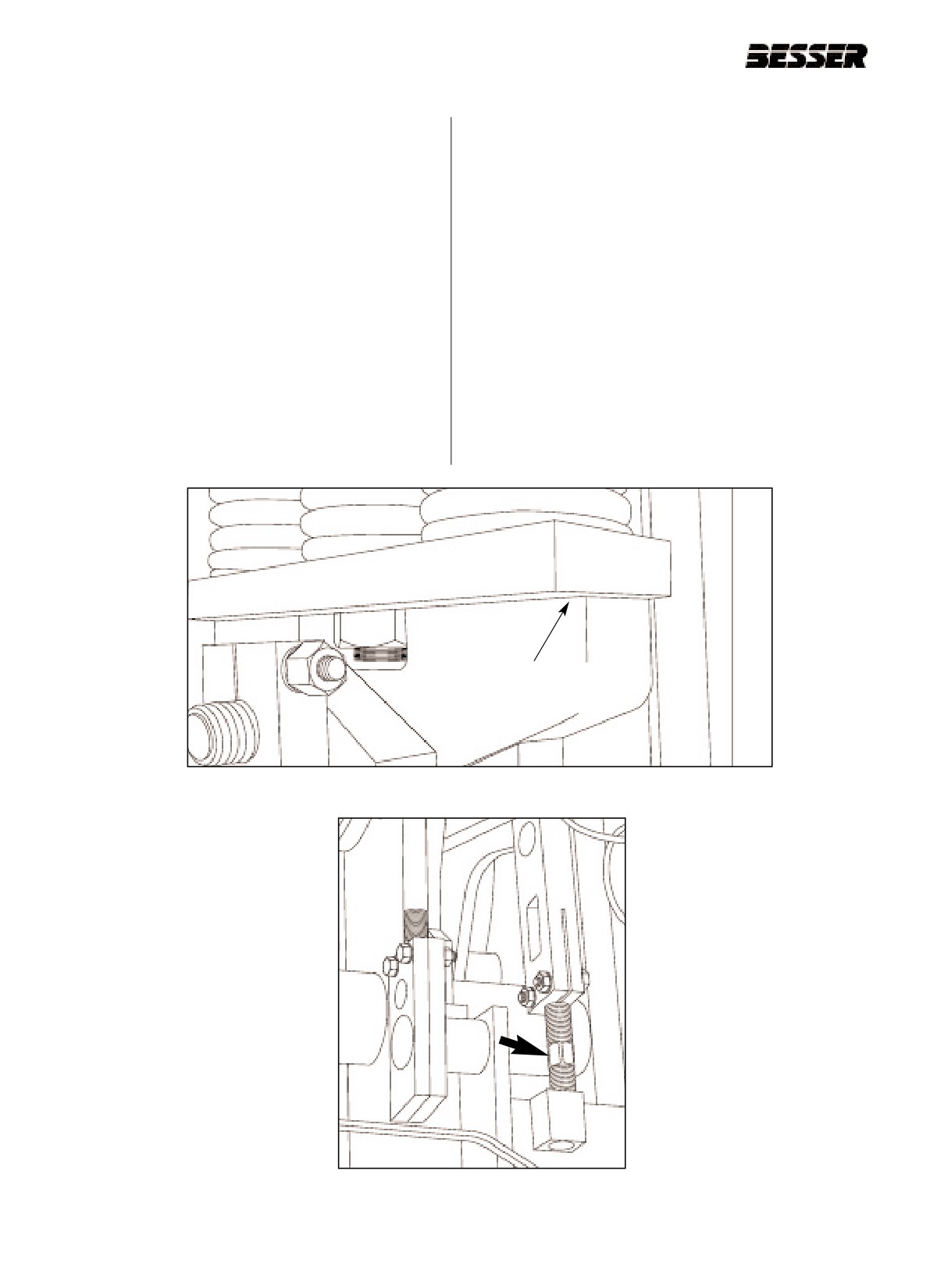
MOLD INSTALLATION
5.9
SPRING OPENING ADJUSTMENT
how many flats you turn the right hand link (see
figure 5.38).
5.9.1 Turn height control “ON”, jog the machine until the
bottom of the mold side bars set down on the
5.9.5 Turn power back on. Hit MCR reset button.
machine side frame.
5.9.6 In order to keep stripper head frame level, turn
5.9.2 The spring opening should be between 1/32”
the left hand stripper head link in the same direc-
[0.8mm] and 1/16” [1.6mm] maximum (see figure
tion. Also turn it the same number of flats as was
5.37). This is all that is required to make most
used to turn the right hand link.
units on a DYNAPAC.
Note: Spring opening may differ on each side.
5.9.3 Shut off clutch and turn power off. Wait until
motor has stopped completely. Also, lock out
5.9.7 Jog the machine to the stripped-through position.
machine.
At this point, the stripper shoes should protrude
through the mold by 1/8” [3mm] to 1/4” [6mm].
5.9.4 If adjustment is needed, adjust the right hand strip-
per head adjusting link (clockwise for more, coun-
terclockwise for less); keep an accurate count of
From 1/32" to 1/16"
[0.8mm to 1/16mm]
Figure 5.37
SPRING OPENING.
Figure 5.38
STRIPPER HEAD LINK (RIGHT SHOWN).
5-26
466361F9710US F1 29OC99
SECTION 5
MOLD INSTALLATION
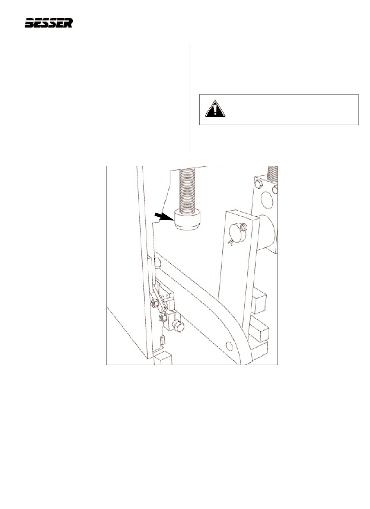
5.9.8
Shut off clutch and turn power off. Wait until
5.9.12 The machine is ready to run; final adjustment
motor has stopped completely. Also, lock out
may be needed when production is started. The
machine.
shock absorbers should be adjusted so they
take equal load on each side (see figure 5.39).
5.9.9
If adjustment is needed, adjust the shock
absorbers. Record the adjustment made for
future calibration.
WARNING: All safety guards must be in
place when the DYNAPAC
5.9.10 Start machine and run machine to second stop,
is running.
when height pins first meet.
5.9.11 Shut off clutch and turn power off. Wait until
motor has stopped completely. Also, lock out
machine.
Figure 5.39
SHOCK ABSORBERS.
466361F9710US F1 29OC99
5-27
SECTION 5
MOLD INSTALLATION
5-28
466361F9710US F1 29OC99
SECTION 6
TIMING THE PALLET FEEDER
SECTION 6
TIMING THE PALLET FEEDER.
It is important that the pallet feeder be well synchronized with the rest of the machine. This adjustment
must be done before the machine is run for the first time and each time a mold change is done.
6.1 INITIAL CONDITIONS
6.1.1
No mold or head in machine.
6.1.5
Front delivery conveyor 31.25" [794mm] above
top of machine base (see section 4).
6.1.2
Inner frame adjusted for height (see section 4).
6.1.6
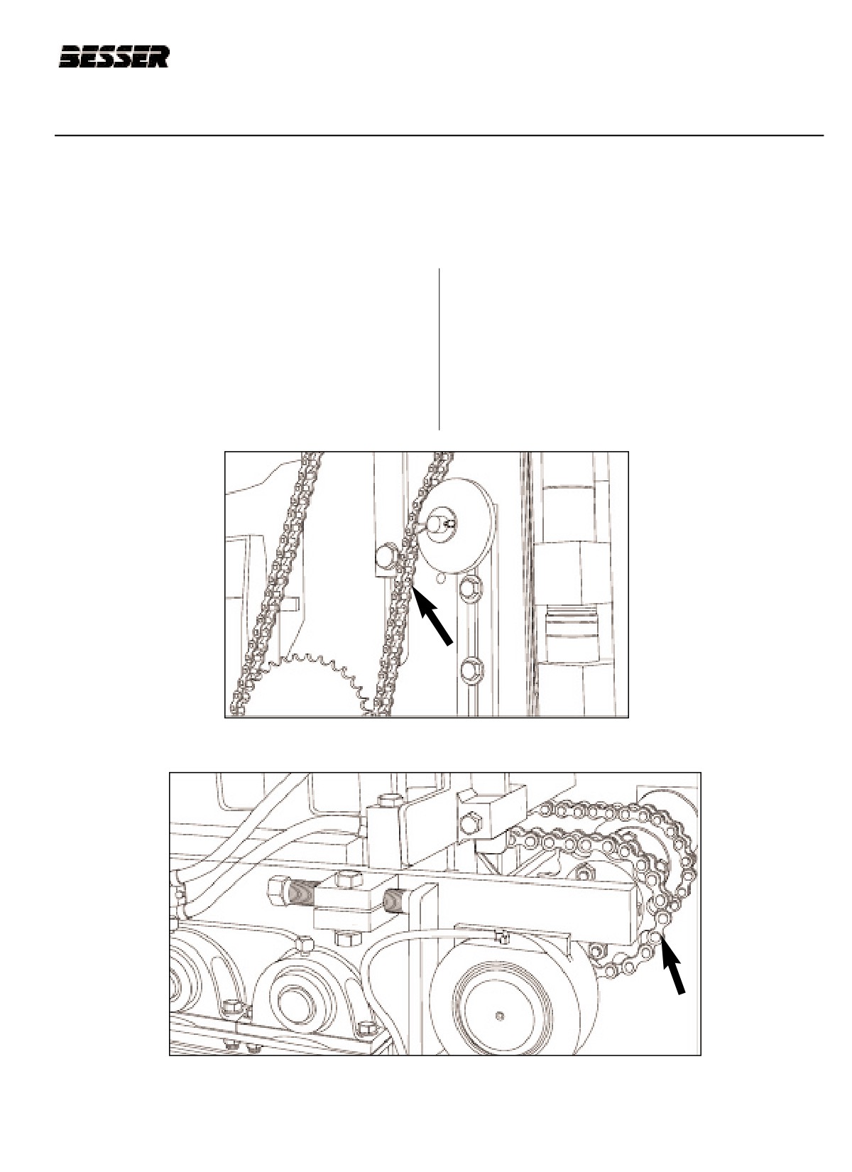
Make sure the pallet feeder drive chain and lug
6.1.3
Pallet receiver stroke set for mold (see section 4).
chains (see figure 6.1 and 6.2) are well adjusted.
To adjust those chains, follow the procedure pre-
6.1.4
Machine has no excessive wear or damage.
sented on the next two pages.
Figure 6.1
PALLET FEEDER DRIVE CHAIN.
Figure 6.2
PALLET FEEDER LUG CHAINS.
466361F9710US F1 29OC99
6-1
SECTION 6
TIMING THE PALLET FEEDER
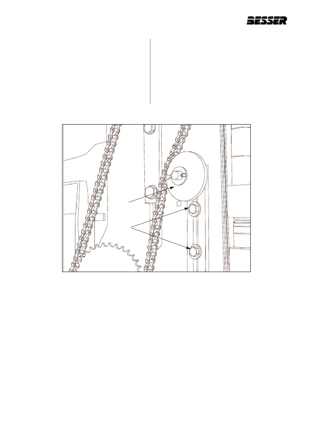
A. PALLET FEEDER DRIVE CHAIN ADJUSTMENT
To adjust the pallet feeder drive chain tension, follow
this procedure:
With the machine off, check pallet feeder drive
chain tension on right hand side of machine.
A. Loosen the fixing bolts (A).
Tension chain until it cannot be moved back and
forth by hand more than 1/4" [6MM]; recheck peri-
B. Move the tensioner (B) up or down as required.
odically (see figure 6.3).
C. Tighten the fixing bolts (A).
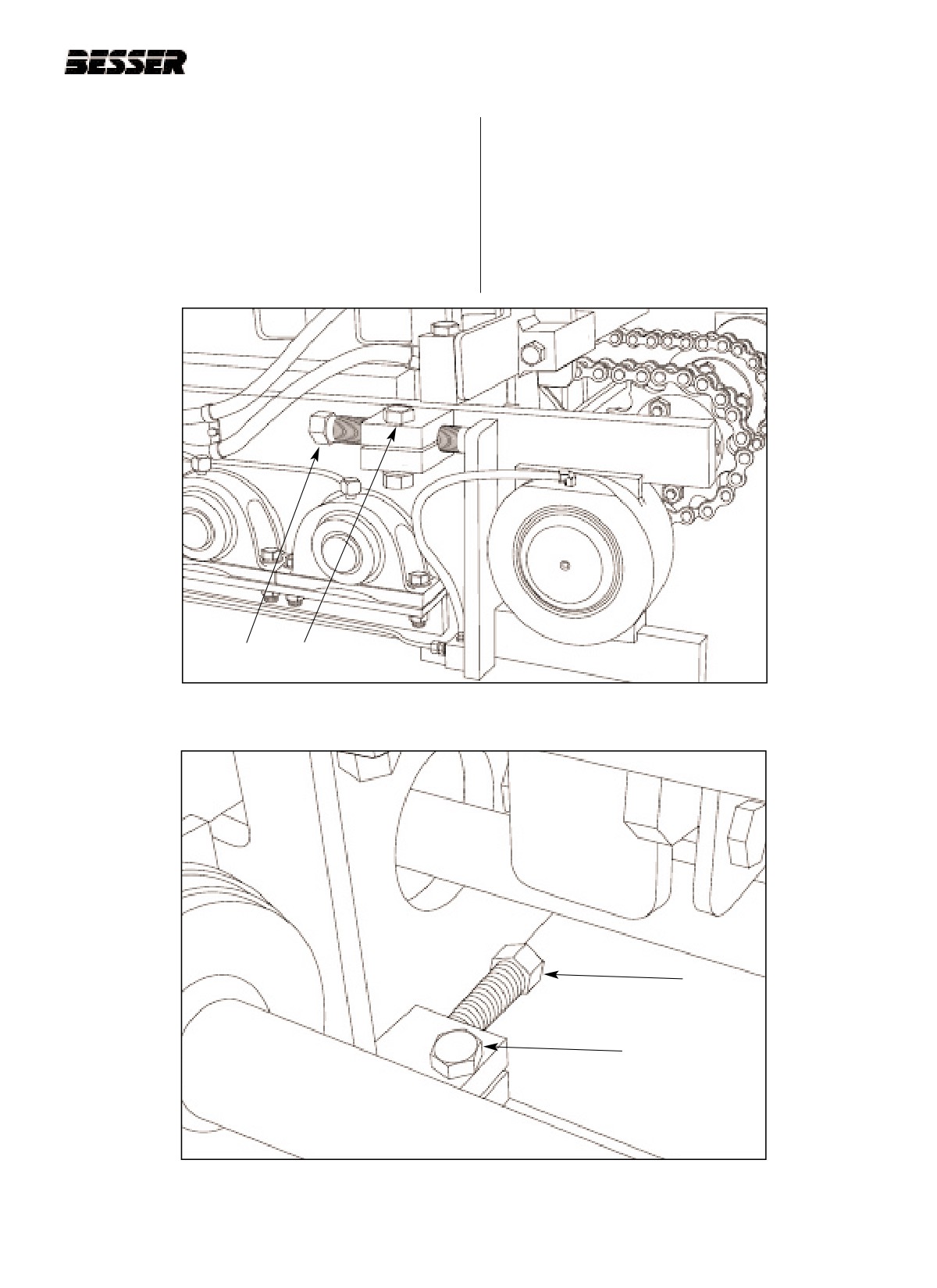
B
A
Figure 6.3
PALLET FEEDER DRIVE CHAIN ADJUSTMENT.
6-2
466361F9710US F1 29OC99
SECTION 6
TIMING THE PALLET FEEDER
B. PALLET FEEDER LUG CHAINS ADJUSTMENT
To adjust the pallet feeder drive chain tension, fol-
low this procedure (see figure 6.4 and 6.5):
With machine off, check tension of pallet feeder lug
chains. Adjust tension at rear end of pallet feeder.
A. Loosen the clamp bolts (A) on the inside and
Bottom strand of each chain sags down in center
on the outside of the machine.
by approximately 1/2" to 3/4" [13mm to 19mm];
recheck periodically.
B. Adjust the tension with the tensioning screw (B).
C. Tighten the clamp bolts (A).
B A
Figure 6.4
PALLET FEEDER CHAIN TENSIONING (RIGHT OUTSIDE VIEW).
B
A
Figure 6.5
PALLET FEEDER CHAIN TENSIONING (RIGHT INSIDE VIEW).
466361F9710US F1 29OC99
6-3
SECTION 6
TIMING THE PALLET FEEDER
6.2
TIMING THE PALLET FEEDER
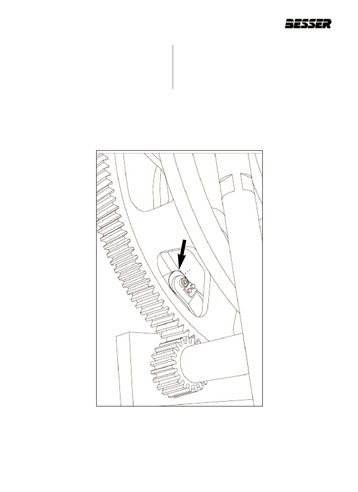
6.2.1
Run machine to align punch marks on pallet rais-
ing cam (innermost cam on left side of machine)
with center of roller that contacts it (see figure
6.6).
Figure 6.6: PALLET RAISING CAM.
6-4
466361F9710US F1 29OC99
SECTION 6
TIMING THE PALLET FEEDER
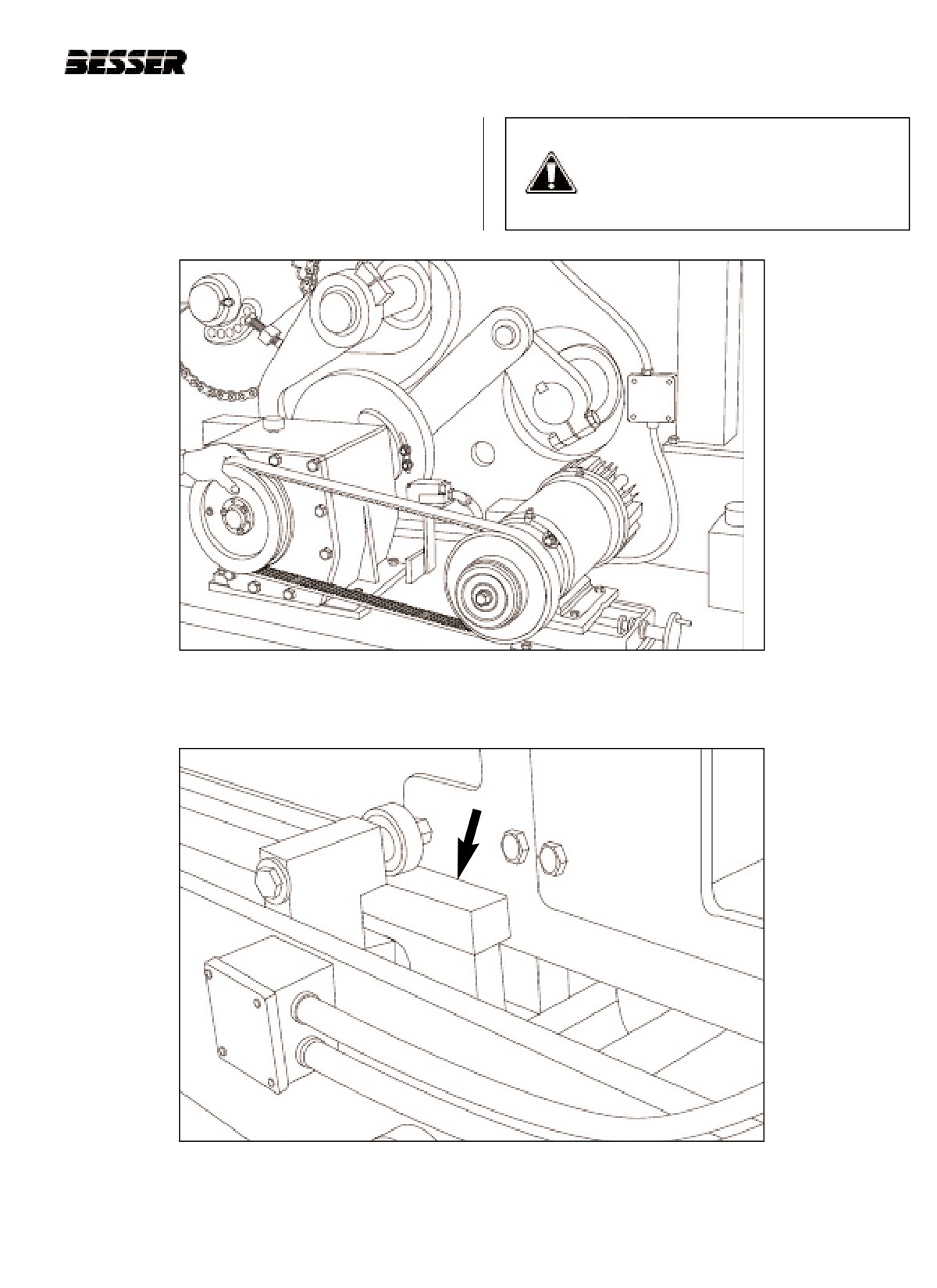
6.2.2
With power off, rotate block delivery drive
CAUTION: Figure below is shown with
sheave by hand (picture 6.7) counterclockwise,
guard removed and is for illustration
until block delivery bars are full forward (see fig-
purposes only. Never operate machine
ure 6.8), both link pins and gear box shaft are in
without the guards. Machine should be
line.
locked and tagged !
Figure 6.7
POSITIONING BLOCK MOVING BARS BY HAND.
Figure 6.8
EXTREME FORWARD POSITION OF BLOCK MOVING BARS.
466361F9710US F1 29OC99
6-5
SECTION 6
TIMING THE PALLET FEEDER
6.2.3
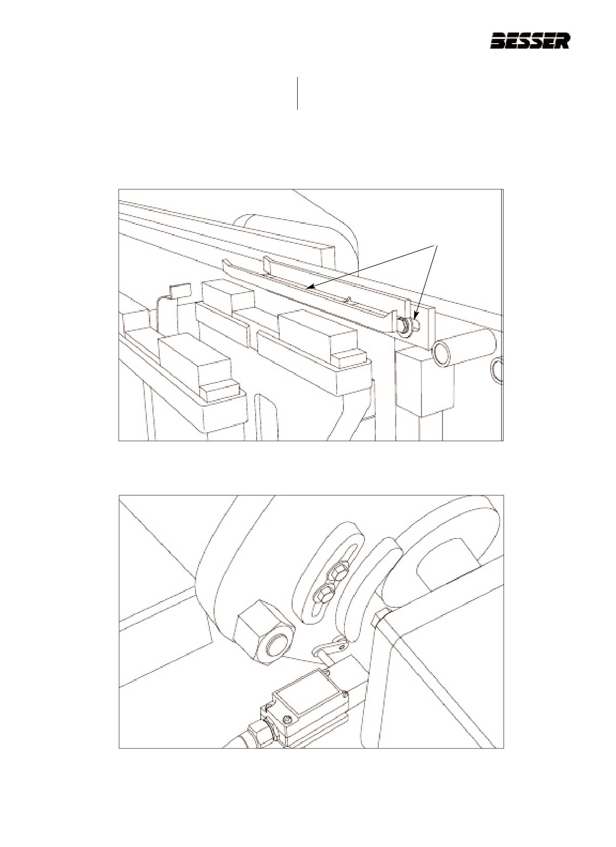
Adjust pallet cradles to be centered with pallet
6.2.4
Set actuator on block delivery drive cam to trip
receiver rubbers (see figure 6.9).
LS-7 (see figure 6.10).
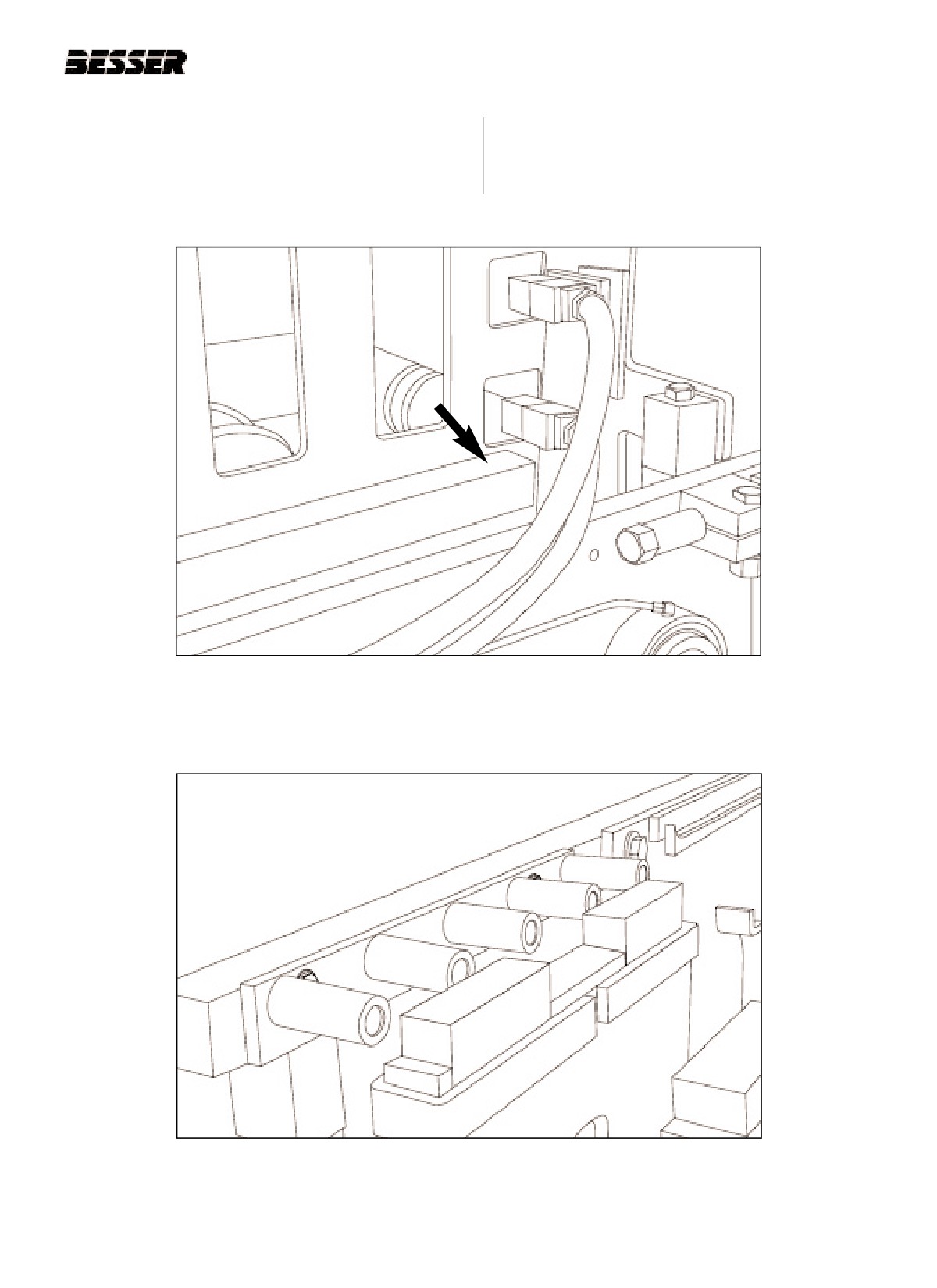
Pallet cradle
adjustment bolts
Figure 6.9
ADJUSTING THE PALLET CRADLE.
Figure 6.10
LIMIT SWITCH LS-7.
6-6
466361F9710US F1 29OC99
SECTION 6
TIMING THE PALLET FEEDER
6.2.5
Rotate block delivery drive counterclockwise
6.2.6
Adjust block fingers to center them with the pallet
(see figure 6.7) until arms are fully back (see fig-
receiver rubbers (see figure 6.12).
ure 6.11). In this position, the pins in the link will
be aligned with the gearbox shaft.
Figure 6.11
EXTREME BACK POSITION OF BLOCK MOVING BARS.
Figure 6.12
ADJUSTING THE BLOCK MOVING BAR FINGERS.
466361F9710US F1 29OC99
6-7
SECTION 6
TIMING THE PALLET FEEDER
6.2.7
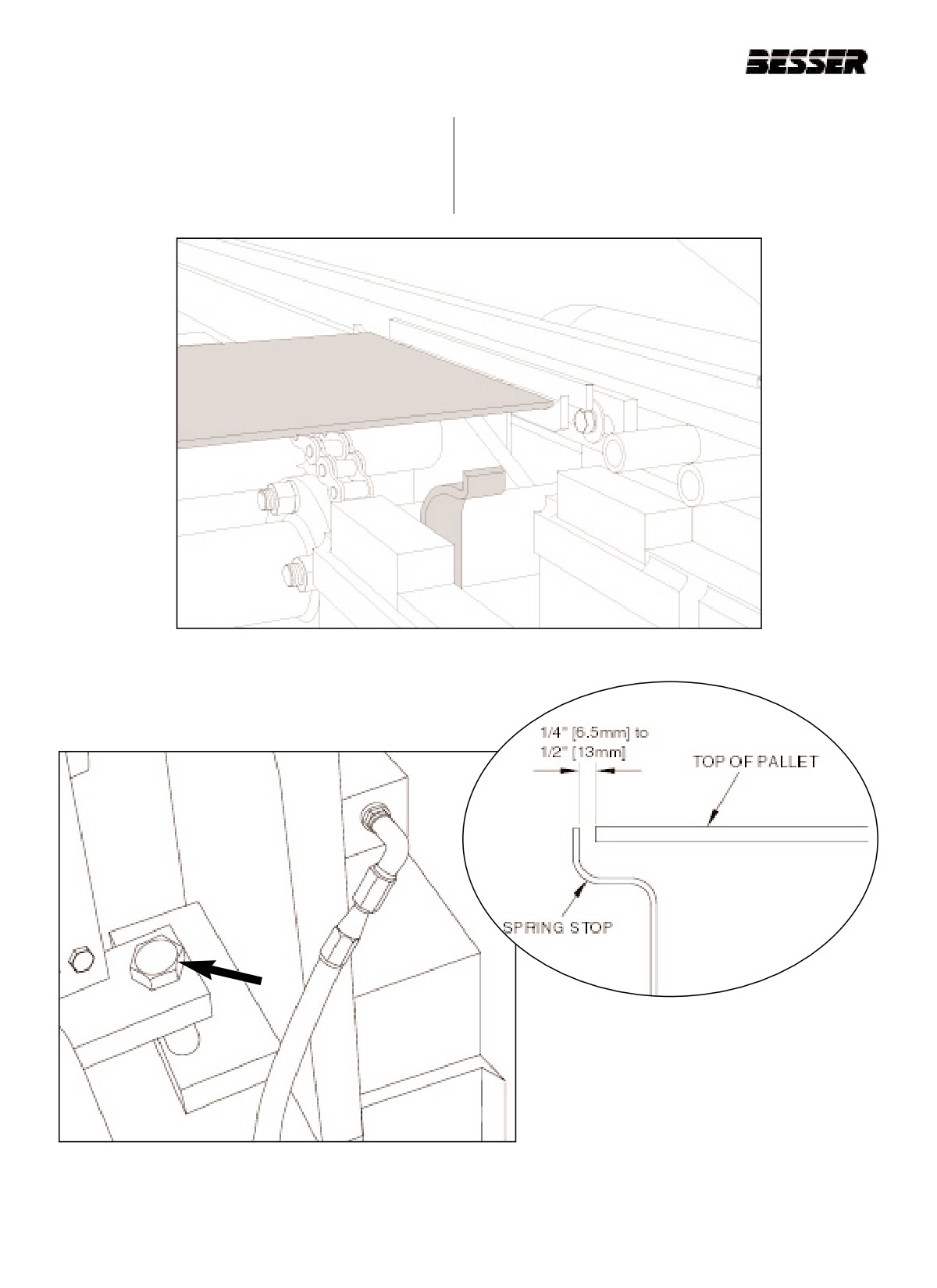
Locate top of pallet spring stops even with top of
6.2.8
Move spring stop assembly so springs are 1/4"
pallet resting on the chains (see figure 6.13).
[6.5mm] to 1/2" [13mm] in front of a pallet cen-
tered in pallet cradles. Also, top of spring should
Note: Pallet cradle is at same height as lug chain.
be flush with top of pallet. (see figure 6.14 and
6.15).
Figure 6.13
PALLET PICK-UP POINT.
Figure 6.15
SPRING STOP ADJUSTMENT.
Figure 6.14
SPRING STOP ADJUSTMENT BOLTS.
6-8
466361F9710US F1 29OC99
SECTION 6
TIMING THE PALLET FEEDER
6.2.9
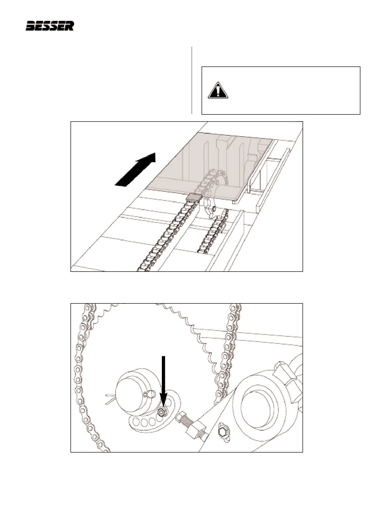
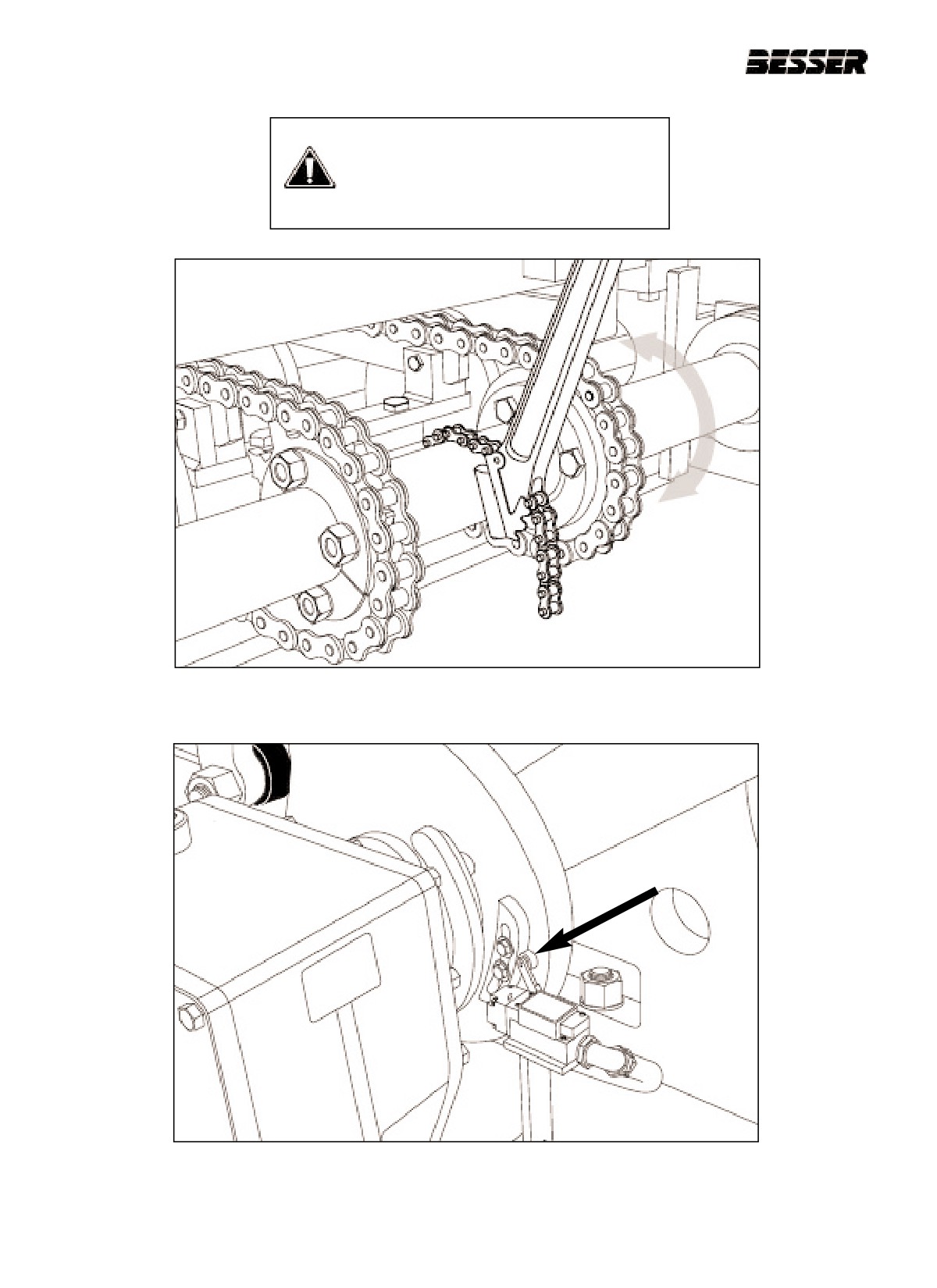
Adjust pallet chain lugs to be even with back of
6.2.10 Adjust the actuator for LS-6 to trip the switch by
pallet (see figure 6.16) by removing shear bolt
2" (see figure 6.19).
and moving shaft (6.17). Use wrench to adjust
lug chain (6.18). Place shear bolt assembly in
CAUTION: Figure below is shown with
holes that align and tighten.
guard removed and is for illustration
purposes only. Never operate machine
without the guards! Machine should be
locked and tagged.
Figure 6.16
LUG (A) SHOULD BE CONTACTING PALLET WHEN IN CRADLE (B).
Figure 6.17
REMOVING THE SHEAR BOLT.
466361F9710US F1 29OC99
6-9
SECTION 6
TIMING THE PALLET FEEDER
CAUTION: Figures below are shown
with guard removed and are for illustra-
tion purposes only. Never operate
machine without the guards. Machine
should be locked and tagged.
Figure 6.18
USING PIPE WRENCH TO ADJUST LUG CHAIN.
Figure 6.19
LIMIT SWITCH ACTUATOR.
6-10
466361F9710US F1 29OC99
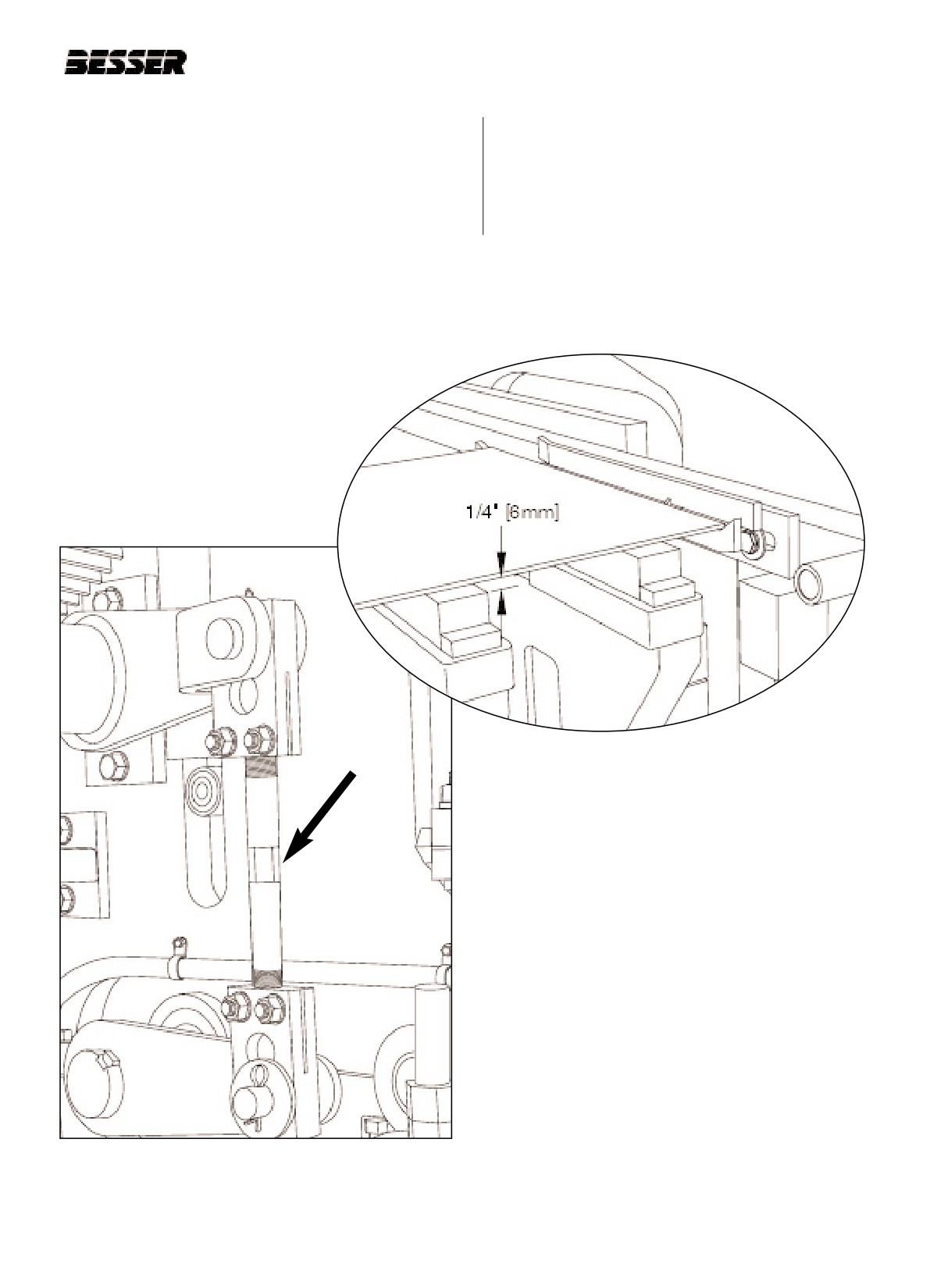
SECTION 6
TIMING THE PALLET FEEDER
6.2.11 Run machine until pallet receiver frame is all the
6.2.12 Place pallet on fingers and adjust block raising
way down; roller is in lowest part of pallet
link on left side of machine (see figure 6.20), to
receiver cam.
obtain 31 1/2" [800mm] from top of base plate to
bottom of pallet. Make sure there is 1/4" [6mm]
of clearance between bottom of pallet and pallet
receiver rubbers (see figure 6.21).
Figure 6.21
PALLET CLEARANCE.
Figure 6.20
PALLET RAISING LINK.
466361F9710US F1 29OC99
6-11
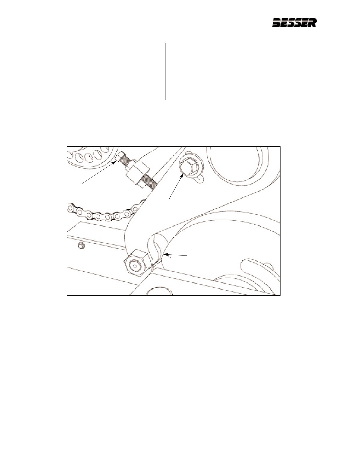
SECTION 6
TIMING THE PALLET FEEDER
6.2.13 Rotate block delivery drive CCW until punch
6.2.15 Run machine and, at the moment where the pal-
marks on high part of cam align with the center
let is beginning to be lifted off the chain, make
of the roller (A) (see figure 6.22).
sure the pallet is centered on the cradle. If pallet
is not in center of cradle, turn off machine and
6.2.14 Loosen the clamp bolt (B) and adjust the jack
readjust chains, refer to 6.2.8. When delivery
screw (C) on the right hand side of machine,
arms come all the way back (see figure 6.11),
until a piece of paper can just be slid between
drive link to cam must be in line with gear box
the cam and roller. Tighten clamp bolt (B).
shaft; if not adjust actuator for LS-6 (see figure
6.19).
C
B
A
Figure 6.22
BLOCK LOWERING ARM ADJUSTMENT.
6-12
466361F9710US F1 29OC99
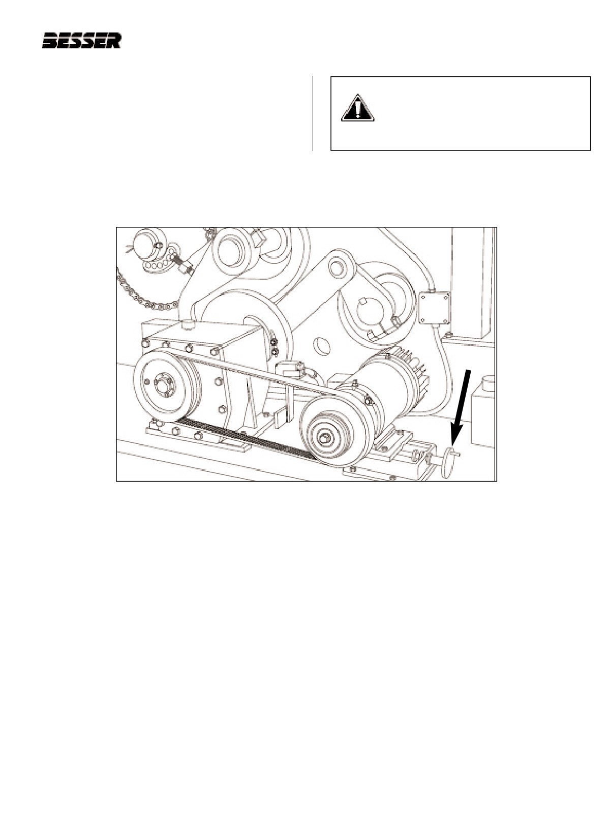
SECTION 6
TIMING THE PALLET FEEDER
6.2.16 Adjust speed of block delivery by moving motor
CAUTION: Figure below is shown with
towards gear reducer to increase speed or away
guard removed and is for illustration
to decrease speed (see figure 6.23). The actua-
purposes only. Never operate machine
tors for limit switches 6 and 7 may have to be
without the guards. Machine should be
adjusted.
locked and tagged.
Figure 6.23
USING CRANK TO ADJUST BLOCK MOVING ARM SPEED.
466361F9710US F1 29OC99
6-13
SECTION 6
TIMING THE PALLET FEEDER
6-14
466361F9710US F1 29OC99
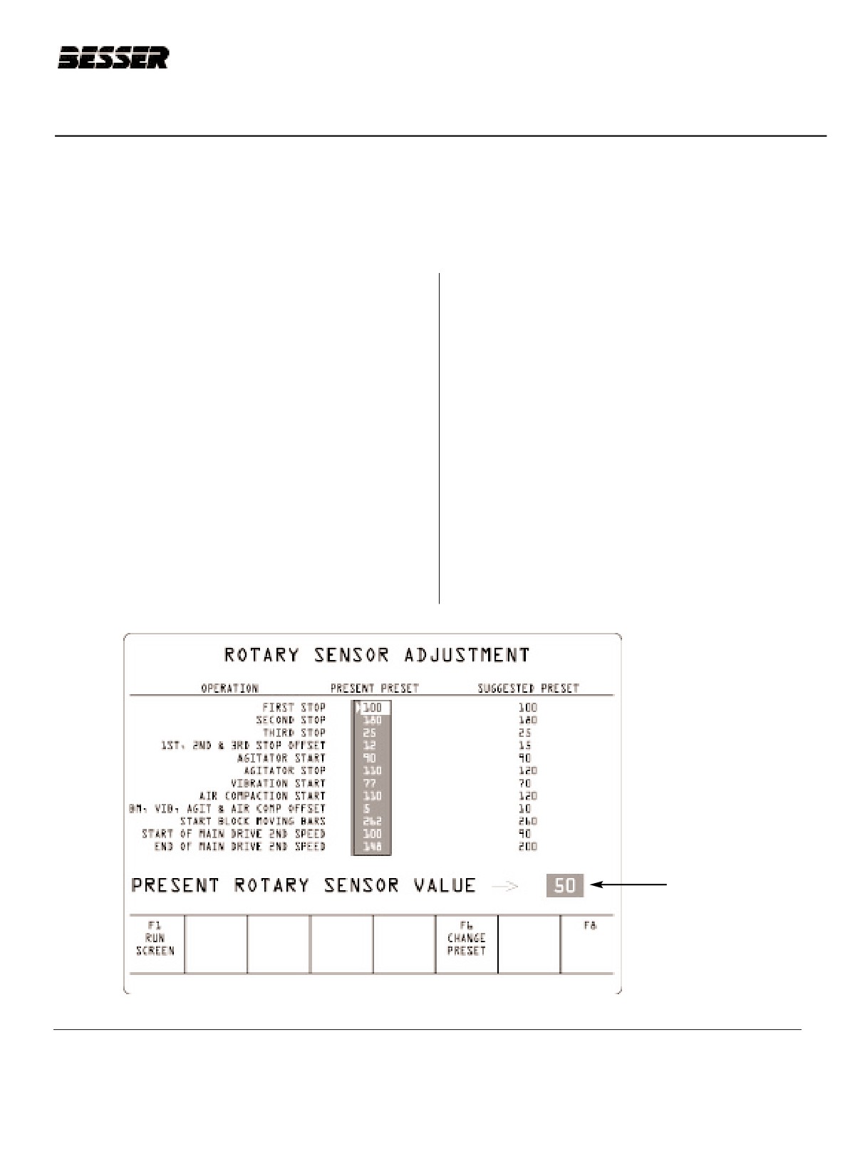
SECTION 7
ROTARY SENSOR SETTING
SECTION 7
ROTARY SENSOR SETTING
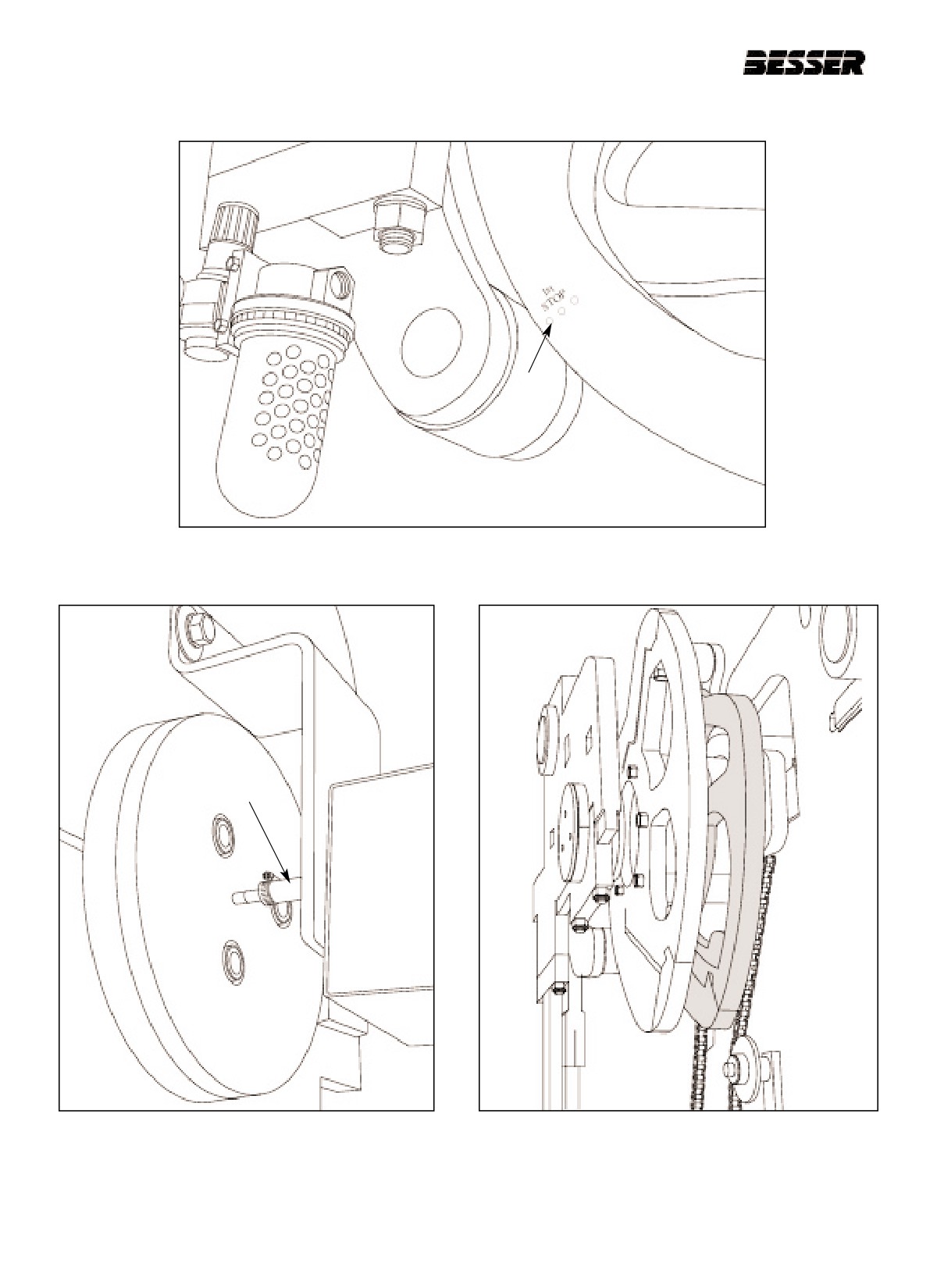
The rotary sensor setting should be done each time the rotary sensor has been removed or disconnected. It
should also be done after a “rotary sensor is out of sync.” fault has appear on the screen.
7.1 As an initial condition, cycle the machine to the “first
7.3 Run the machine to “second stop” position which is
stop” position “First stop” is obtained when the
controlled by the rotary sensor. The roller should be
punch marks on the cam are in line with the
centered with the “second stop” marks on the pallet
roller.(see figure 7.2). In this position, the feedbox
receiver cam. “Second stop” is the point where the
should be all the way forward and the roller should be
stripper head shaft roller just falls off the high lobe of
centered on the first stop mark of the pallet receiver
the stripper head raising cam. The stripper head rais-
cam. At this point, the “Rotary sensor value” should
ing cam is the second cam from the outside on the
be indicating 1000 on the rotary sensor adjustment
right side of the machine (see figure 7.4).
screen (see figure 7.1, for more details see section
10.4). To reach this screen, press “F2” from the main
Note: As the machine ran from first stop to second
menu.
stop, the value must count in a positive direc-
tion (meaning from 1000 to 1800 in 10 incre-
7.2 If the rotary sensor value shown in the screen is not
ments). If the value is not incrementing in a
1000, loosen rotary sensor coupler (A) (as shown in
positive direction, rotate the screw on the back
figure 7.3) and make adjustment. To adjust, turn
of the rotary sensor to opposite position.
rotary sensor coupler until 1000 is reached. Use the
screen to monitor the rotary sensor. Make sure you
tighten rotary sensor coupler before resuming adjust-
ment.
ROTARY SENSOR
VALUE
Figure 7.1
ROTARY SENSOR ADJUSTMENT SCREEN.
466361F9710US F1 29OC99
7-1
SECTION 7
ROTARY SENSOR SETTING
Figure 7.2
“FIRST STOP” (R.H. side of machine).
A
Figure 7.3
ROTARY SENSOR COUPLER
Figure 7.4
STRIPPER HEAD RAISING CAM.
ADJUSTMENT.
7-2
466361F9710US F1 29OC99
SECTION 8
OPERATING THE MACHINE
SECTION 8
OPERATING THE MACHINE
8.1
OPERATING THE DYNAPAC
This section will guide you, the operator, through the
The pallet has to be lifted at one point in the process; a
actual operation of the DYNAPAC. First, read the
cam does that. A stripper head frame is also connected
sequence of the machine in order to have a good
to two different cams to move it up and down. A strip-
understanding of how the machine works and how you
per head, which is part of the mold, has to be installed
can make adjustments to produce perfect concrete
on the stripper head frame. This stripper head will
blocks or pavers. Of course, the machine has to be
press on top of the units to compact them. A pallet
setup before it can be operated properly. Adjustments
receiver frame is located below the stripper head. This
on the pallet feeder, on machine timing and on adjust-
component holds the pallet and the mold in place dur-
ments for specific molds have to be made prior to the
ing the concrete unit forming process (stripper head is
sequence outlined in this section.
pressing and the mold is vibrating). The pallet receiver
is connected by links to a cam on the main shaft to
move up and move down through gravity. The last two
cams will bring a feed box forward and back. This feed
8.2
HOW A CONCRETE PRODUCT
box pushes the material (concrete) to the mold.
MACHINE WORKS
Concrete will fall into the feedbox through a hopper
located on top of the machine. An agitator grid placed
The DYNAPAC is a three-at-a-time block machine
in the feedbox will agitate the material as it falls in the
rated at up to 1,800 blocks per hour. A concrete unit is
mold for better distribution of the concrete. The Agitator
made when concrete is fed into a mold and is then
is powered by a motor located on the feedbox.
vibrated and compacted. Once it has been compacted,
it is stripped out of the mold and delivered onto a con-
Finally, one motors on each side of the machine vibrate
veyor. Many types of molds can be fitted on the
the mold. The vibration occurs when the concrete is fed
machine to obtain a wide variety of products.
in by the feedbox and when the units are being com-
pressed by the stripper head. Vibration only lasts a few
Refer to section 3 “MACHINE DESCRIPTION" to learn
seconds but it is crucial to making concrete units.
about the names and locations of the machine’s com-
ponents.
All of the machine’s movements are controlled by cams
located on a main shaft. As the cams turn with the main
shaft, they activate rollers which are connected to link
rods which in turn are connected to the components.
These components either go forward and back or up
and down. One cam brings a component forward (or
up) and another brings it back (or down). The main
shaft is powered by a motor and a clutch. The motor
runs all the time. It is the clutch that will stop and start
all machine movements. The only operation not activat-
ed by the main cam is the block delivery arm which
feeds empty pallets to the mold and pallet with blocks
to the exit conveyor. This component is powered by a
motor and is independent because it sometimes has to
keep running while the rest of the machine is stopped.
466361F9710US F1 29OC99
8-1
SECTION 8
OPERATING THE MACHINE
8.3
MACHINE SEQUENCE OF OPERATION:
1. Machine cycle begins with feedbox ready to start forward when main drive clutch solenoid is energized.
2. With feedbox on its way forward, vibrators and agitators begin functioning.
3. Feedbox completes its forward stroke and stops over mold. At this point, the machine stops (at the position called
"FIRST STOP").
While in "first stop", the following occurs:
- Feed timer is turned ON
- Feed timer times out, which re-starts machine.
4. Feedbox returns to home position, at which time-
- Agitator turns OFF
(At this time, machine keeps cycling)
5. Stripper head drops onto concrete in mold. At this point, machine stops (this position is "SECOND STOP").
While at "second stop", the following occurs:
- Height pin control circuit is turned ON
- Finish timer starts and autofeed control circuit is enabled.
- When height pins meet, finish indicator stops and delay timer begins. At this point, the autofeed mechanism or
feed time is adjusted, and if necessary (actual finish time was not equal to desired finish time).
- Delay timer times out which:
- Starts the strip delay timer - Turns off vibrators
- Strip delay timer times out which-.
- Turns ON main drive
6. Machine strips units from the mold. If a fault occurs, machine stops. If no fault occurs, pallet moving bars pick up
empty incoming pallet from pallet feeder conveyor. Pallet with block is deposited on block moving support fingers
while:
- Stripper head is raising
- Block moving bars travel to their most forward position.
- If limit switch LS-7 is tripped before rotary sensor reaches “third stop” position (approximately 25o), NO "THIRD
STOP".
- If rotary sensor reaches “third stop” position before Ls-7 is tripped, main drive stops until LS-7 is tripped, this is
the "THIRD STOP" position.
7. Block moving bars lower and return to extreme rear position.
- LS-6 tripped which-stops Block moving bars.
Machine cycle is complete; a new one begins.
8-2
466361F9710US F1 29OC99
SECTION 8
OPERATING THE MACHINE
8.4
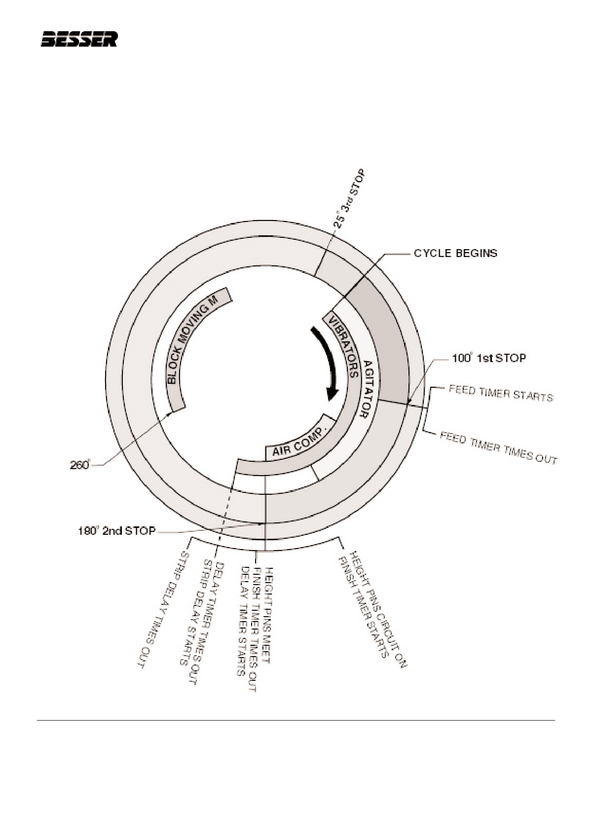
MACHINE SEQUENCE AND THE ROTARY SENSOR
The figure below represents the machine sequences in accordance with the rotary sensor values (in degrees). It will
help you understand better how the machine cycle works and how to adjust parameters such as feed time, finish
time, delay time and strip delay time which are crucial in making good quality concrete products.
Figure 8.1
MACHINE SEQUENCE CYCLE.
466361F9710US F1 29OC99
8-3
SECTION 8
OPERATING THE MACHINE
8.5
INITIAL STARTING POSITION
8.6
PROCEDURES TO RUN MACHINE FOR
FIRST TIME OR WHEN NEW MOLD
Make sure all the following are set properly.
HAS BEEN INSTALLED
1.
Make sure “EMERGENCY STOP” button is pulled
Make sure pre-run procedures have been done and
out.
initial start-up position is obtained before going
through these adjustments.
2.
Make sure “CLUTCH” switch is “OFF”.
First, the operator has to decide of the quality of con-
3.
Make sure “VIBRATOR” switch is “OFF”.
crete units he wants to produce.
4.
Press and release “MCR RESET” push button.
The quality depends on two (2) factors:
Machine will start.
-the mix.
-the machine adjustments.
5.
Press and release “VIBRATOR START” push but-
ton. The vibrators will start.
The machine adjustments for making units are done by
adjusting the forming time and the autofeed adjust-
6.
Press F1 from the run screen and verify all selec-
ment. The forming time includes the feed time, the fin-
tions are correct:
ish time and the delay time. The following is a descrip-
tion of these parameters on the machine which will help
- Height pins are [ENABLED].
you understand how to adjust the machine.
- Agitator is [ON].
Note: These explanations are better covered in sec-
tion 9: Hand & Machine Interface.
- Air compaction is [ON].
FEED TIME:
- Slump mode is [OFF].
Amount of time the feed box is stopped over the mold.
This will control the amount of material (concrete)
- Pallet cleaner is [OFF].
placed in the mold.
- Auto feed time adjust is [OFF].
FINISH TIME:
Preset time that you will expect desired finish time,
- Auto feed is in [AUTO].
from the moment stripper head shoes hit material to
when height pins meet each other. Machine will adjust
- Auto height pin by pass is [DISABLE].
the finish time by adjusting the autofeed mechanism or
the feed time (the operator has to select which one he
- Dual vibration is [OFF].
prefers the machine to change. See section 9.3: "Hand &
Machine Set-up".
7.
Set the “VIBRATOR” switch to “AUTO”.
DELAY TIME:
8.
Set “CLUTCH” switch to “ON”.
The time of vibration after height pins meet.
Note: Enabling these items may not be required for all
STRIP DELAY TIME:
products.
Time from the moment vibration stops to when units
are stripped out of the mold. Note that the strip delay
does not influence the quality of the units. The strip
The machine will sound an alarm for 7 seconds and
delay will simply slow down the process.
begin cycling.
1. Adjust parameter for feed time to approximately
To stop the machine, set the clutch switch to “OFF” or
1 1/2 seconds.
push in the “EMERGENCY STOP” button.
2. Adjust parameter for finish time to approximately
1 1/2 seconds.
8-4
466361F9710US F1 29OC99
SECTION 8
OPERATING THE MACHINE
3.
Adjust parameter for delay time to approximately
1 1/2 seconds.
4.
Set "Autofeed" to "MAN" position.
5.
Adjust it to 1/2" [13mm].
6.
Start making units (start machine) (see section
8.5).
7.
Check units coming out. Check for cracks, dimen-
sions and density.
8.
If units are not perfect, modify finish time until units
are perfect. To modify finish time, refer to section
9.5: "Timer adjustment".
9.
If units continue being cracked, check delay time; it
is probably not sufficient. Too much material intro-
duced in the mold can also cause the cracks.
10. If the units are still not perfect, see section 10:
"Troubleshooting" for more details.
11. Set the "Autofeed Mechanism" to "auto". See sec-
tion 9.3: "Hand & Machine Set-up".
Note: We strongly suggest you use the "Autofeed
Mechanism" for most units. It will allow you to
produce consistent products. The use of
"Autofeed Mechanism" is not recommended for
low height units.
466361F9710US F1 29OC99
8-5