BESSER DYNAPAC 3 AT A TIME (466361F9710US). OPERATION / MAINTENANCE MANUAL - page 1
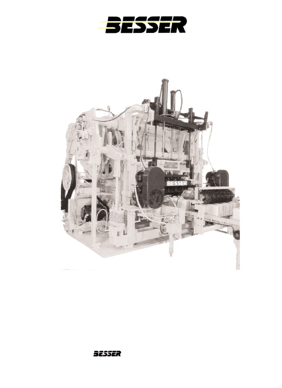
DYNAPAC
3 AT A TIME
OPERATION/MAINTENANCE MANUAL
466361F9710US
OCTOBER 1999
• US$250
World Headquarters
801 Johnson St.
• Alpena, Michigan, 49707
• U.S.A.
Phone (517) 354-4111
COMPANY NAME:
SERIAL NUMBER:
ASSEMBLY NUMBER:
WIRING DIAGRAM NUMBER:
INSTALLATION DRAWING NUMBER:
DYNAPAC
Table of Contents
TABLE OF CONTENTS
LIST OF TABLES
iv
LIST OF ILLUSTRATIONS
v
SAFETY BULLETIN
ix
SAFETY SIGNS
x
SPECIFICATIONS
xii
SECTION 1
LOCKING OUT THE MACHINE
1-1
SECTION 2
INTRODUCTION
2.1
HOW A CONCRETE PRODUCT MACHINE WORKS
2-1
2.2
OPERATOR ORIENTATION
2-2
SECTION 3
MACHINE DESCRIPTION
3.1
PALLET RECEIVER ASSEMBLY
3-1
3.2
STRIPPER HEAD FRAME ASSEMBLY
3-2
3.3
AUTOFEED MECHANISM ASSEMBLY
3-3
3.4
GENERAL COMPONENTS
3-4
SECTION 4
MACHINE SET-UP FOR SPECIFIC MOLD
4.1
3 5/8" HIGH UNITS IN A 3 7/8" HIGH NON-RAMPED MOLD WITH A 14 3/16"
HIGH STRIPPER HEAD ASSEMBLY
4-1
4.2
5 5/8" HIGH UNITS IN A 6 3/16" HIGH NON-RAMPED MOLD WITH A 14 3/16"
HIGH STRIPPER HEAD ASSEMBLY
4-11
4.3
80 MM HIGH UNITS IN A 86 MM HIGH NON-RAMPED MOLD WITH A 360 MM
HIGH STRIPPER HEAD ASSEMBLY
4-21
4.4
60 MM HIGH UNITS IN A 67 MM HIGH NON-RAMPED MOLD WITH A 360 MM
HIGH STRIPPER HEAD ASSEMBLY
4-31
SECTION 5
MOLD & STRIPPER HEAD INSTALLATION
5.1
BESSER MOLD ASSEMBLY & TORQUE REQUIREMENTS
5-1
5.2
JOGGING AND RUNNING THE MACHINE
5-1
5.3
REMOVING THE MOLD
5-2
5.4
INSTALLING THE MOLD
5-7
5.5
ADJUSTING THE MOLD
5-13
5.6
APRON PLATE ADJUSTMENT
5-18
5.7
ADJUSTING THE STRIPPER HEAD
5-21
5.8
COMPRESSION CALCULATION
5-25
5.9
SPRING OPENING ADJUSTMENT
5-26
466361F9710US F1 29OC99
i
DYNAPAC
Table of Contents
SECTION 6
TIMING THE PALLET FEEDER
6.1
INITIAL CONDITIONS
6-1
6.2
TIMING THE PALLET FEEDER
6-4
SECTION 7
ROTARY SENSOR SETTING
7-1
SECTION 8
OPERATING THE MACHINE
8.1
OPERATING THE DYNAPAC
8-1
8.2
HOW A CONCRETE PRODUCT MACHINE WORKS
8-1
8.3
MACHINE SEQUENCE OF OPERATION
8-2
8.4
MACHINE SEQUENCE AND THE ROTARY SENSOR
8-3
8.5
INITIAL STARTING POSITION
8-4
8.6
PROCEDURES TO RUN MACHINE FOR FIRST TIME OR WHEN NEW
MOLD HAS BEEN INSTALLED
8-4
SECTION 9
GRAPHIC CONTROL STATION
9.0
GRAPHIC CONTROL STATION
9-1
9.1
BLOCK MACHINE RUN SCREEN
9-4
9.2
FAULT MESSAGE ON BLOCK MACHINE RUN SCREEN
9-6
9.3
HAND & MACHINE SET UP (F1)
9-7
9.4
ROTARY SENSOR ADJUSTMENT (F2)
9-8
9.5
TIMER ADJUSTMENT (F3)
9-9
9.6
INPUT / OUTPUT STATUS (F4)
9-12
9.7
PRODUCT TABLE (F5)
9-14
9.8
CYCLE TIMER (F6)
9-20
9.9
DIAGNOSTICS (F7)
9-21
9.10
PRODUCT QUANTITY CONTROL (F9)
9-28
9.11
SMARTPAC ADJUSTMENT (F10)
9-30
SECTION 10
TROUBLESHOOTING
10.1
SMALL LOGIC CONTROLLER FAULTS
10-1
10.2
SOLUTIONS TO CORRECT DEFORMED AND CRACKED BLOCKS
10-5
SECTION 11
MAINTENANCE
11.1
PREVENTIVE MAINTENANCE
11-1
11.2
SERVICE AND REPAIRS
11-2
11.3
TRABON PUMP MAINTENANCE
11-12
11.4
BEARING MAINTENANCE
11-14
11.5
SMARTPAC MAINTENANCE AND CARE
11-19
11.6
SLC CONTROLLER MAINTENANCE
11-20
ii
466361F9710US F1 29OC99
DYNAPAC
Table of Contents
SECTION 12
VIBRATION SYSTEM
12.1 SMARTPAC
12-1
12.2 FREQUENCY DRIVE OPERATION
12-4
12.3 STANDARD VIBRATION SYSTEM
12-6
12.4 BESCOSTOP MOTOR/BRAKE CHECKS
12-8
APPENDIX A
(Counters, Integer Words and Timers)
A-1
APPENDIX B
(Electrical Diagrams)
B-1
APPENDIX C
(Electrical Panel)
C-1
APPENDIX D
(Limit Switch Locations)
D-1
466361F9710US F1 29OC99
iii
DYNAPAC
List of tables
LIST OF TABLES
SPECIFICATIONS
A STEEL PALLET SPECIFICATIONS
xii
B DYNAPAC ELECTRICAL DATA
xiii
C SUMMARY OF ACOUSTICS
xv
SECTION 11
MAINTENANCE
11.1
PREVENTIVE MAINTENANCE
11-1
11.2
DRIVE MOTOR TABLE
11-2
11.3
BESCODYNE CLUTCH/BRAKE UNIT
11-2
11.4
PINION SHAFT
11-8
11.5
CAM SHAFT
11-8
11.6
FEED, STRIPPER HEAD AND PALLET RECEIVER SHAFTS & LINKS
11-8
11.7
FEEDBOX
11-9
11.8
PALLET & BLOCK DELIVERY
11-9
11.9
PALLET & BLOCK MOVING BARS
11-10
11.10 PALLET & BLOCK SUPPORT SHAFT
11-10
11.11 PALLET & BLOCK DRIVE
11-10
11.12 TOOLS
11-11
iv
466361F9710US F1 29OC99
DYNAPAC
List of illustrations
LIST OF ILLUSTRATIONS
SECTION 4
MACHINE SET-UP FOR SPECIFIC MOLD
4.1
Pallet Receiver Shaft Position
4-1
4.2
Stripper Head Shaft and Links
4-2
4.3
“First Stop”
4-3
4.4
Disconnecting the 2 Autofeed Linkages
4-3
4.5
Inner Frame Adjustment
4-4
4.6
Loosen “T” Clamps on Both Sides
4-4
4.7
Bolts at all 4 Corners
4-5
4.8
Loosen Bolts
4-5
4.9
Hydraulic Jack System
4-5
4.10
No Spacers
4-6
4.11
Apron Plate Above Mold Throat Adjustment
4-6
4.12
Cam Inserts
4-7
4.13
Pallet Receiver Rubbers Position
4-7
4.14
Upper Height Stops
4-8
4.15
Shock Absorbers Adjustment
4-8
4.16
4 3/8” [111mm] Blocking under Stripper Head Frame
4-9
4.17
Pallet Receiver Shaft Position
4-11
4.18
Stripper Head Shaft and Links
4-12
4.19
“First Stop”
4-13
4.20
Disconnecting the Autofeed Linkages
4-13
4.21
Inner Frame Adjustment
4-14
4.22
Loosen “T” Clamps on Both Sides
4-14
4.23
Bolts at all 4 Corners
4-15
4.24
Loosen Bolts
4-15
4.25
Hydraulic Jack System
4-15
4.26
2 1/4” [57mm] of Spacers
4-16
4.27
Apron Plate Above Mold Throat Adjustment
4-16
4.28
Cam Inserts
4-17
4.29
Pallet Receiver Rubbers Position
4-17
4.30
Upper Height Stops
4-18
4.31
Shock Absorbers Adjustment
4-18
4.32
2 1/8” [54mm] Blocking under Stripper Head Frame
4-19
4.33
“First Stop”
4-21
4.34
Disconnecting the Autofeed Linkages
4-21
4.35
Inner Frame Adjustment
4-22
4.36
Loosen “T” Clamps on Both Sides
4-22
4.37
Bolts at all 4 Corners
4-23
4.38
Loosen Bolts
4-23
4.39
Hydraulic Jack System
4-23
4.40
83mm [3 1/4”] of Spacers
4-24
4.41
Apron Plate Above Mold Throat Adjustment
4-24
4.42
Removing Stripping Cam Inserts
4-25
4.43
Pallet Receiver Shaft Position
4-25
4.44
Stripper Head Shaft and Links
4-26
4.45
Pallet Receiver Rubbers Above Base Plate
4-27
4.46
Link Rod
4-27
4.47
Upper Height Stops
4-28
4.48
Installing Shock Absorbers and Adjusting
4-28
466361F9710US F1 29OC99
v
DYNAPAC
Lists of illustrations
4.49
95mm [3 3/4”] Blocking under Stripper Head Frame
4-29
4.50
“First Stop”
4-31
4.51
Disconnecting the Autofeed Linkages
4-31
4.52
Inner Frame Adjustment
4-32
4.53
Loosen “T” Clamps on Both Sides
4-32
4.54
Bolts at all 4 Corners
4-33
4.55
Loosen Bolts
4-33
4.56
Hydraulic Jack System
4-33
4.57
63mm [2 1/2”] of Spacers
4-34
4.58
Apron Plate Above Mold Throat Adjustment
4-34
4.59
Stripping Cam Inserts
4-35
4.60
Pallet Receiver Shaft Position
4-35
4.61
Stripper Head Shaft and Links
4-36
4.62
Pallet Receiver Rubbers Above Base Plate
4-37
4.63
Link Rod
4-37
4.64
Upper Height Stops
4-38
4.65
Installing Shock Absorbers and Adjusting
4-38
4.66
95mm [3 3/4”] Blocking under Stripper Head Frame
4-39
SECTION 5
MOLD & STRIPPER HEAD INSTALLATION
5.1
“First Stop”
5-2
5.2
Wooden Blockings in Mold
5-3
5.3
Removing Bolts from Stripper Head Plate
5-3
5.4
Attaching Stripper Head Frame with Safety Chain
5-4
5.5
Raising the Vibrator Motors with Screw Jack
5-5
5.6
Mold Locks in Open Position
5-5
5.7
Mold Insertion Device in Lower Position
5-6
5.8
Mold is Chained, Ready to be Taken out of Machine
5-6
5.9
Attaching Stripper Head Frame with Safety Chain
5-7
5.10
Mold Locks in Open Position
5-8
5.11
Stripper Head Positioned in Mold
5-8
5.12
Mold is Chained, ready to be Placed in Machine
5-9
5.13
Placing Mold and Stripper Head in Machine
5-10
5.13b Securing the Mold
5-10
5.14
Raising the Vibrator Motors with Screw Jack
5-11
5.15
Bolt Stripper Head Plate to Stripper Head Frame
5-12
5.16
Mold Resting on the Pallet Receiver
5-12
5.17
Side to Side Dimension
5-13
5.18
Pallet Receiver Link Rod
5-14
5.19
Upper Guide Liner Adjustment Screw
5-15
5.20
Pallet Receiver Frame Adjustment
5-15
5.21
Centering the Mold
5-16
5.22
Using the 1” [25.4mm] Dimension to Center the Mold
5-16
5.23
Vibrating Motor Height Adjustment Screw
5-17
5.24
Apron Plate Clearance
5-18
5.25
Apron Plate Clearance
5-18
5.26
Apron Plate Adjustment (Forward to Back)
5-19
5.27
Shoes 4” [102mm] Above Mold
5-20
5.28
Height Pins Adjustment
5-20
5.29
L.H. Stripper Head Link
5-21
5.30
Stripper Shoes Position
5-21
5.31
Lower Guide Liner Adjustment Screw
5-22
5.32
Stripper Head Frame Adjustment
5-22
vi
466361F9710US F1 29OC99
DYNAPAC
List of illustrations
5.33
Feedbox Adjustment
5-23
5.34
Feedbox Linkage
5-23
5.35
Tightening the Head Bolts
5-24
5.36
Mold and Stripper Head Dimensions for Height Pins Adjustments
5-25
5.37
Spring Opening
5-26
5.38
Stripper Head Link
5-26
5.39
Shock Absorbers
5-27
SECTION 6
TIMING THE PALLET FEEDER
6.1
Pallet Feeder Drive Chain
6-1
6.2
Pallet Feeder Lug Chains
6-1
6.3
Pallet Feeder Drive Chain Adjustment
6-2
6.4
Pallet Feeder Chain Tensioning
6-3
6.5
Pallet Feeder Chain Tensioning
6-3
6.6
Pallet Raising Cam
6-4
6.7
Positioning Block Moving Bars by Hand
6-5
6.8
Extreme Forward Position of Block Moving Bars
6-5
6.9
Adjusting the Pallet Cradle
6-6
6.10
Limit Switch LS-7
6-6
6.11
Extreme Back Position of Block Moving Bars
6-7
6.12
Adjusting the Block Moving Bar Fingers
6-7
6.13
Pallet Pick-up Point
6-8
6.14
Spring Stop Adjustment Bolts
6-8
6.15
Spring Stop Adjustment
6-8
6.16
Lug (A) Should be Contacting Pallet When in Cradle (B)
6-9
6.17
Removing the Shear Bolt
6-9
6.18
Using Pipe Wrench to Adjust Lug Chain
6-10
6.19
Limit Switch Actuator
6-10
6.20
Pallet Raising Link
6-11
6.21
Pallet Clearance
6-11
6.22
Block Lowering Arm Adjustment
6-12
6.23
Using Crank to Adjust Block Moving Arm Speed
6-13
SECTION 7
ROTARY SENSOR SETTING
7.1
Rotary Sensor Adjustment Screen
7-1
7.2
“First Stop”
7-2
7.3
Rotary Sensor Coupler Adjustment
7-2
7.4
Stripper Head Raising Cam
7-2
SECTION 8
MACHINE SEQUENCE CYCLE
8.1
Machine Sequence Cycle
8-3
SECTION 9
GRAPHIC CONTROL STATION
9.1
Graphic Control Station
9-2
SECTION 11
MAINTENANCE
11.1
Bescodyne Clutch/Brake Unit
11-2
11.2
Stack Wear Grooves
11-4
11.3
Brake Clutch Stacks for Wear
11-4
11.4
Input Pulley Belt Tension
11-6
11.5
Output Pulley Belt Tension
11-6
11.6
Pinion Shaft
11-6
466361F9710US F1 29OC99
vii
DYNAPAC
List of illustrations
11.7
Gear Tooth Gap
11-6
11.8
Pinion Shaft
11-7
11.9
Bull Gear
11-7
11.10
11-10
11.11
11-10
11.12 The Trabon Lube Pump
11-12
11.13 Bearings
11-16
11.14 SLC Controller Battery, Fuses, Eprom and Circuit Breakers
11-21
12.1
Smartpac
12-1
12.2
Smartpac Panel
12-3
viii
466361F9710US F1 29OC99
DYNAPAC
Safety Bulletin
SAFETY BULLETIN
This notice is issued to advise you that some previously accepted shop practices may not be keeping up
with changing Federal and State Safety and Health Standards. Your current shop practices may not
emphasize the need for proper precautions to insure safe operation and use of machines, tools, automatic
loaders and allied equipment and/or warn against the use of certain solvents or other cleaning substances
that are now considered unsafe or prohibited by law. Since many of your shop practices may not reflect
current safety practices and procedures, particularly with regard to the safe operation of equipment, it is
important that you review your practices to ensure compliance with Federal and State Safety and Health
Standards.
IMPORTANT
The operation of any machine or power-operated device can be extremely hazardous unless
proper safety precautions are strictly observed. Observe the following safety precautions:
Always be sure proper guarding is in place for all pinch, catch, shear, crush and nip points.
Always make sure that all personnel are clear of the equipment before starting it.
Always be sure the equipment is properly grounded.
Always turn the main electrical panel off and lock it out in accordance with published lockout/tag-
out procedures prior to making adjustments, repairs, and maintenance.
Always wear appropriate protective equipment like safety glasses, safety shoes, hearing
protection and hard hats.
Always keep chemical and flammable material away from electrical or operating equipment.
Always maintain a safe work area that is free from slipping and tripping hazards.
Always be sure appropriate safety devices are used when providing maintenance and repairs to all
equipment.
Never exceed the rated capacity of a machine or tool.
Never modify machinery in any way without prior written approval of the Besser Engineering
Department.
Never operate equipment unless proper maintenance has been regularly performed.
Never operate any equipment if unusual or excessive noise or vibration occurs.
Never operate any equipment while any part of the body is in the proximity of potentially haz-
ardous areas.
Never use any toxic flammable substance as a solvent cleaner.
Never allow the operation or repair of equipment by untrained personnel.
Never climb or stand on equipment when it is operational.
It is important that you review Federal and State Safety and Health Standards on a continual basis. All
shop supervisors, maintenance personnel, machine operators, tool operators, and any other person
involved in the setup, operation, maintenance, repair or adjustment of Besser-built equipment should read
and understand this bulletin and Federal and State Safety and Health Standards on which this bulletin is
based.
466361F9710US F1 29OC99
ix
DYNAPAC
Safety Signs
SAFETY SIGNS
Sign
Description
Required
1
Electric Motor
1
2
All Machines
1
All Panels
1
3
Mixer
4
4
Block Machine
1
SF-7 Cuber
8
BTO-6
2
Overhead Block Transfer
3
Depalleter
2
AF-7 Block Pusher
2
5
Concrete Products Machine
1
6
Concrete Products Machine
1
7
Concrete Products Machine
2
8
Besser-Matic
4
9
Besser-Matic
4
10
Pallet Transport System
4
11
LSC-40A
4
Overhead Block Transfer
4
12
Conveyors
6
13
SF-7 Cuber
8
14
AF-7 Block Pusher
2
Pallet Transport System
4
15
All Machines
1
All Panels
1
16
SF-7 Cuber
3
AF-7 Block Pusher
2
Slat Conveyors
2
To order safety decals, contact your local Besser representative
or the Besser Central Order Department.
Thank you!
x
466361F9710US F1 29OC99
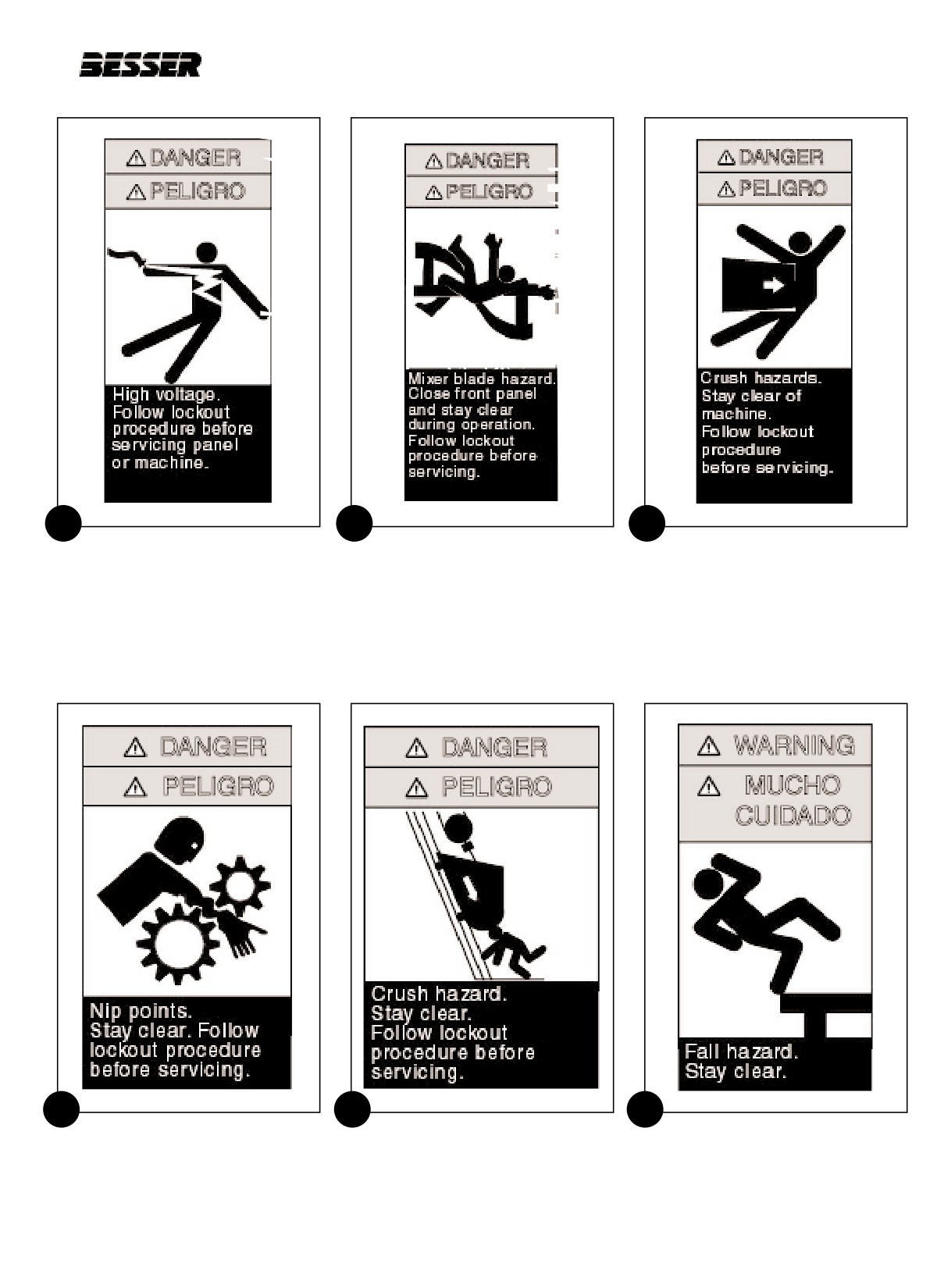
DYNAPAC
Safety Signs
1
2
3
Large 113236F0409
113237F0410
113240F0307
High Voltage
Mixer Blade Hazard
Crush Hazard
Width 4 1/2 inch
Width 4 1/2 inch
Width 3 1/2 inch
Height 9 5/8 inch
Height 1/4 inch
Height 7 1/2 inch
Small 113236F0204
High Voltage
Width 2 inch
Height 4 1/8 inch
4
5
6
114692F1006
114688F0906
114689F0804
Nip Points
Crush Hazard
Fall Hazard
Width 5 3/4 inch
Width 6 1/4 inch
Width 4 1/2 inch
Height 9 1/2 inch
Height 9 1/2 inch
Height 7 3/4 inch
466361F9710US F1 29OC99
xi

DYNAPAC
Table of Contents
7
8
9
114690F0805
114691F1006
113242F0409
Falling Objects
Shear and Fall Hazards
Crush Hazard
Width 4 3/4 inch
Width 5 3/4 inch
Width 4 1/2 inch
Height 8 inch
Height 9 3/4 inch
Height 9 5/8 inch
11
Vertical: 113245F0704
Horizontal: 113245F1005
10
12
113243F0410
Crush Hazard
113249F0410
Falling Objects
Vertical: Width 4 1/8 inch
Safety instructions decal-
Width 4 1/2 inch
Vertical: Height 7 inch
Suggested Lock-out procedure
Height 10 inch
Horizontal: Width 10 inch
Width 4 inch
Horizontal: Height 5 3/4 inch
Height 10 inch
xii
466361F9710US F1 29OC99
DYNAPAC
Table of Contents
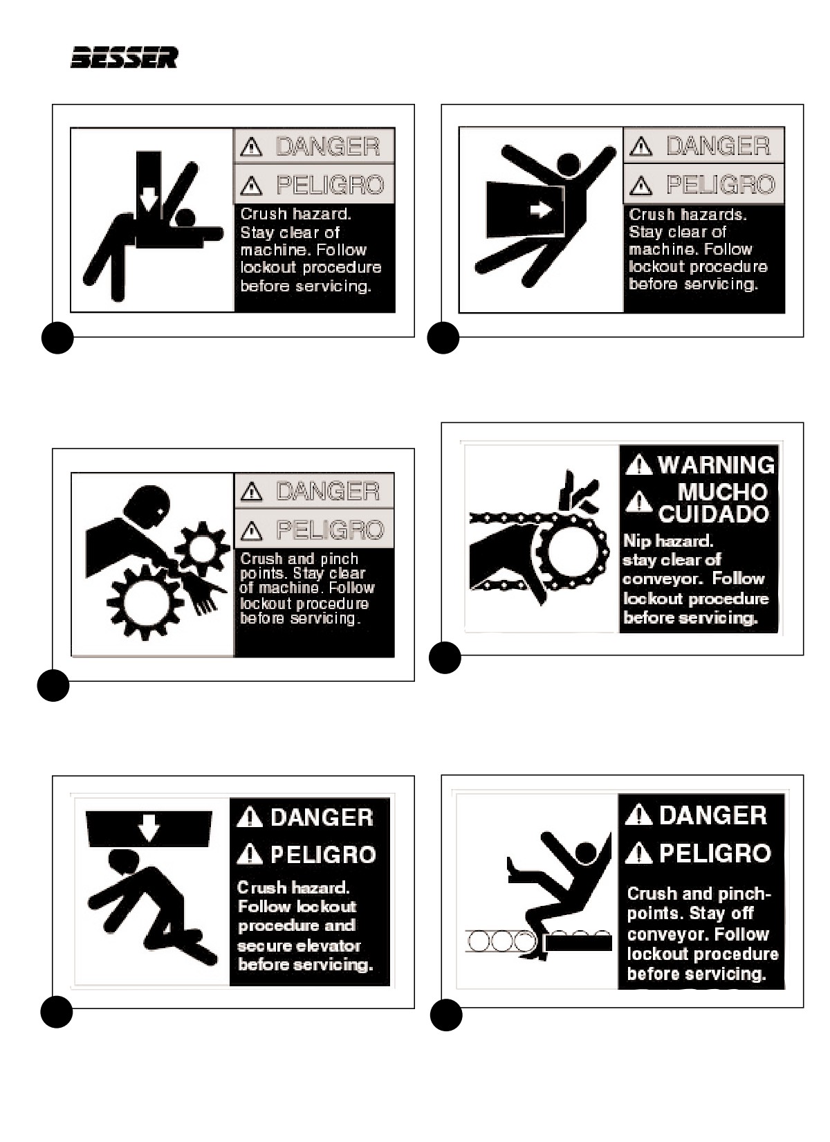
13
14
113238F1005
113239F0604
Crush Hazard
Crush Hazard
Width 10 inch
Width 6 5/8 inch
Height 5 3/4 inch
Height 4 inch
16
113246F0704
Nip Hazard
15
113241F0605
Width 7 inch
Crush and Pinch Points
Height 4 1/2 inch
Width 6 5/8 inch
Height 4 inch
17
18
113247F1006
113250F1006
Crush Hazard
Crush and Pinch Points Hazard
Width 10 inch
Width 10 inch
Height 6 inch
Height 6 inch
466361F9710US F1 29OC99
xiii
DYNAPAC
Specifications
SPECIFICATIONS
TOTAL WEIGHT:
52,000 Lbs [23587 Kg]
AIR LINE FITTING DIMENSIONS:
3/4" [19mm] I.D.
MINIMUM AIR PRESSURE:
80 psi [5.5 bars]
NOISE RATING:
102 to 114 DBA
MACHINE SPEED:
up to 10 cycles / minute
PRODUCTION CAPACITY:
up to 1800 blocks / hour
MINIMUM PRODUCT SIZE REQUIREMENT:
2" high [51mm]
MAXIMUM PRODUCT SIZE REQUIREMENT:
12" high [304.8mm]
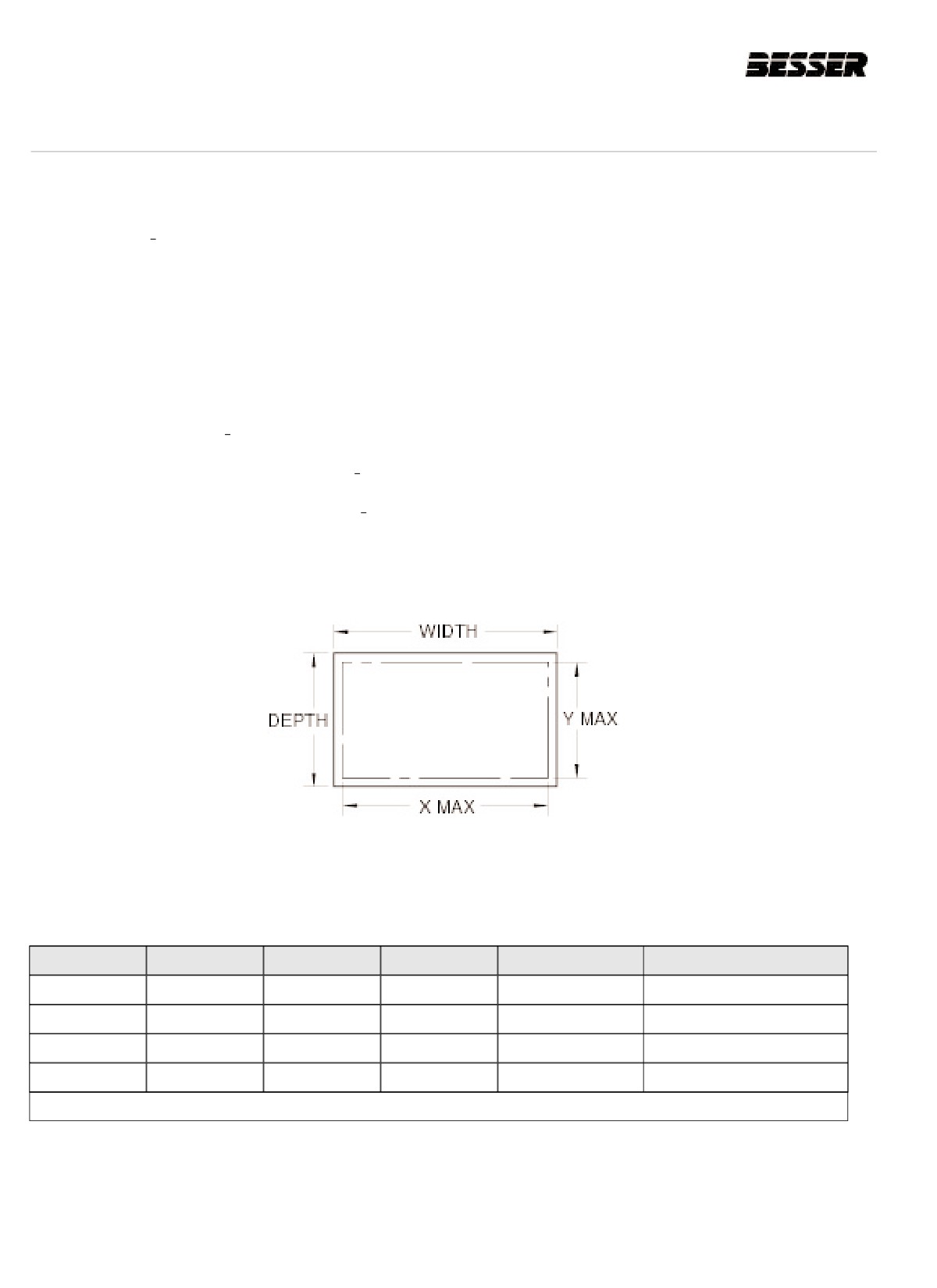
PALLET REQUIREMENTS:
WIDTH & DEPTH = Actual size of steel pallet.
XMAX & YMAX = Maximum production area of steel pallet.
WIDTH
DEPTH
THICK.
X
Y
PALLET NO.
26.0" [660mm]
18.5" [470mm]
.313" [8mm]
25.0" [635mm]
17.5" [445mm]
470750F0001
26.0" [660mm]
20.5" [521mm]
.313" [8mm]
25.0" [635mm]
19.5" [495mm]
470750F0002
29.0" [737mm]
18.5" [470mm]
.313" [8mm]
28.0" [711mm]
17.5" [445mm]
470750F0004
29.0" [737mm]
20.5" [521mm]
.313" [8mm]
28.0" [711mm]
19.5" [495mm]
470750F0005
THICKNESS TOLERANCE : -0.010" [0.25mm] / +0.030" [0.76mm]
Table A
STEEL PALLET SPECIFICATIONS
xiv
466361F9710US F1 29OC99

DYNAPAC
Specifications
DYNAPAC ELECTRICAL DATA
CONTROL
BRANCH
BRANCH
BRANCH
BRANCH
SHORT
PLANT POWER
TOTAL
TOTAL
PANEL
CIRCUIT
CIRCUIT
CIRCUIT
CIRCUIT
CIRCUIT
SUPPLY
HORSEPOWER
KILOWATTS
TRANSFORMER
DISTRIBUTION
FUSE FRS-R
FEEDER
FEEDER
INTERRUPTING
(VOLTS)
(HP)
(KW)
(VOLT-AMPS)
SWITCH (AMPS)
(AMPS)
THHN
CONDUIT
CAPACITY (AIC)
220V-240V
2 AWG
1.5 IN.
50.5
37.6
1500
200
200
200,000
50/60 HZ
67.5MM2
38MM
380V
2 AWG
1.0 IN.
50.5
37.6
1500
200
150
200,000
50 HZ
33.6MM2
25MM
415V
3 AWG
1 IN.
50.5
37.6
1500
200
125
200,000
50 HZ
26.7MM2
25MM
440V-480V
4 AWG
1 IN.
50.5
37.6
1500
100
100
200,000
50/60 HZ
21.6MM2
25MM
575V
6 AWG
0.75 IN.
50.5
37.6
1500
100
80
200,000
60 HZ
13.3MM2
20MM
Table B
DYNAPAC ELECTRICAL DATA
Please consult the table above to find the appropriate electrical data for your DYNAPAC. First, find your corresponding
plant power supply in the first left column. You will then find the corresponding electrical data on the same row than your
power plant supply.
EX: Your power plant supply is 460V at 60 Hz. According to the table, you will then get these values:
PLANT POWER SUPPLY :
460 Volts - 60 Hertz
TOTAL HORSEPOWER :
50.5
TOTAL KILOWATTS :
37.6
CONTROL PANEL TRANSFORMER :
1500 volt-amps
BRANCH CIRCUIT DISTRIBUTION SWITCH :
100 amp
BRANCH CIRCUIT FUSE RECOMMENDED (FRS-R) :
100 amp
BRANCH CIRCUIT FEEDER RECOMMENDED (THHN) :
4 AWG (21.6mm2)
BRANCH CIRCUIT FEEDER CONDUIT RECOMMENDED :
1 in.(25mm)
SHORT CIRCUIT INTERRUPTING CAPACITY :
200,000 AIC
466361F9710US F1 29OC99
xv
DYNAPAC
Specifications
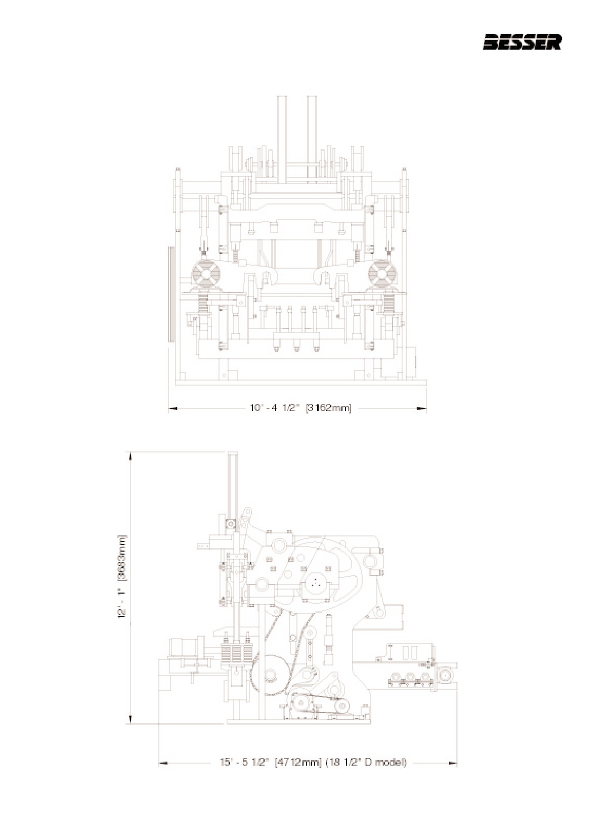
OVERALL DIMENSIONS:
xvi
466361F9710US F1 29OC99
DYNAPAC
Specifications
SUMMARY OF ACOUSTICS
Files #
+ MEM # Frq. Condition
Distance
Overall
< 550Hz
> 550Hz
C
A
C
A
C
A
1.
+
1/21
5 kHz
Start of cycle
0.5m
112
111
109
100
110
110
2.
+
2/22
5 kHz
End of cycle
0.5m
116
114
112
105
113
114
3.
+
3/23
5 kHz
Start of cycle
0.5m
4.
+
4/24
1 kHz
End of cycle
0.5m
5.
+
5/25
5 kHz
Start of cycle
1.0m
111
108
108
98
107
107
6.
+
6/26
5 kHz
End of cycle
1.0m
114
111
112
103
110
110
7.
+
7/27
1 kHz
Start of cycle
1.0m
8.
+
8/28
1 kHz
End of cycle
1.0m
9.
+
9/29
5 kHz
Start of cycle
2.0m
110
106
108
96
105
105
10.
+
10/30
5 kHz
End of cycle
2.0m
110
109
109
99
108
108
11.
+
11/31
1 kHz
Start of cycle
2.0m
12.
+
12/32
1 kHz
End of cycle
2.0m
13.
+
13/33
5 kHz
Start of cycle/
0.5m
113
112
108
103
112
112
no pallet
14.
+
14/34
5 kHz
End of cycle/
0.5m
110
108
107
102
106
106
no pallet
15.
+
15/35
1 kHz
Start of cycle/
0.5m
no pallet
16.
+
16/36
1 kHz
End of cycle
0.5m
no pallet
Table C SUMMARY OF ACOUSTICS
466361F9710US F1 29OC99
xvii
DYNAPAC
Specifications
xviii
466361F9710US F1 29OC99
SECTION 1
LOCKING OUT THE MACHINE
SECTION 1
LOCKING OUT THE MACHINE
CAUTION: For safety reasons, it is
IMPORTANT for all personnel to read
and understand the following Lock-out
procedure.
Whenever you have to make adjustments, service
the machine, do any kind of checkup or stop pro-
duction of units, you must lock out the machine.
Locking out insures that the machine will not
start-up accidentally, thus preventing possible
grave injuries. It is a question of safety for all per-
sonnel.
When you have to lock out the machine, please
follow this procedure:
1. Announce lockout to other employees.
2. Turn power OFF at main panel.
3. Lockout power in OFF position.
4. Put key in pocket.
5. Clear machine of all personnel.
6. Test lockout by hitting run button.
7. Block, chain or release stored energy
sources.
8. Clear machine of personnel before restarting
machine.
Note: You will also find this procedure on a decal
affixed on the machine.
466361F9710US F1 29OC99
1-1
SECTION 1
LOCKING OUT THE MACHINE
1-2
466361F9710US F1 29OC99
SECTION 2
INTRODUCTION
SECTION 2
INTRODUCTION
2.1
HOW A CONCRETE PRODUCT
MACHINE WORKS.
The DYNAPAC is a three-at-a-time block machine rated
The pallet has to be lifted at one point in the process; a
at up to 1,800 blocks per hour. A concrete masonry unit
cam does that. A stripper head frame is also connected
is made when concrete is fed into a mold and is then
to two different cams to move it up and down. A stripper
vibrated and compacted. Once it has been compacted,
head, which is part of the mold, has to be installed on
it is stripped out of the mold and delivered onto a con-
the stripper head frame. This stripper head will press on
veyor. Many types of molds can be fitted on the machine
top of the units to compact them. A pallet receiver frame
to obtain a wide variety of products.
is located below the stripper head. This component
holds the pallet and the mold in place during the con-
Refer to Section 3 MACHINE DESCRIPTION, to learn
crete unit forming process ( stripper head is pressing
about the names and locations of the machine’s compo-
and the mold is vibrating). The pallet receiver is con-
nents.
nected by links to a cam on the main shaft to move up
and moves down through gravity. The last two cams will
All of the machine’s movements are controlled by cams
bring a feed box forward and back. This feed box push-
located on a main shaft. As the cams turn with the main
es the material (concrete) to the mold. Concrete will fall
shaft, they activate rollers which are connected to link
into the feedbox through a hopper located on top of the
rods which in turn are connected to the components.
machine. An agitator grid placed in the feedbox will agi-
These components either go forward and back or up
tate the material as it falls in the mold for better distribu-
and down. One cam brings a component forward (or up)
tion of the concrete. The Agitator is powered by a motor
and another brings it back (or down). The main shaft is
located on the feedbox.
powered by a motor and a clutch. The motor runs all the
time. It is the clutch that will stop and start all machine
Finally, one motors on each side of the machine vibrate
movements. The only operation not activated by the
the mold. The vibration occurs when the concrete is fed
main cam is the block delivery arm which feeds empty
in by the feedbox and when the units are being com-
pallets to the mold and pallet with blocks to the exit con-
pressed by the stripper head. Vibration only lasts a few
veyor. This component is powered by a motor and is
seconds but it is crucial to making concrete units.
independent because it sometimes has to keep running
while the rest of the machine is stopped.
466361F9710US F1 29OC99
2-1
SECTION 2
INTRODUCTION
2.2
OPERATOR ORIENTATION
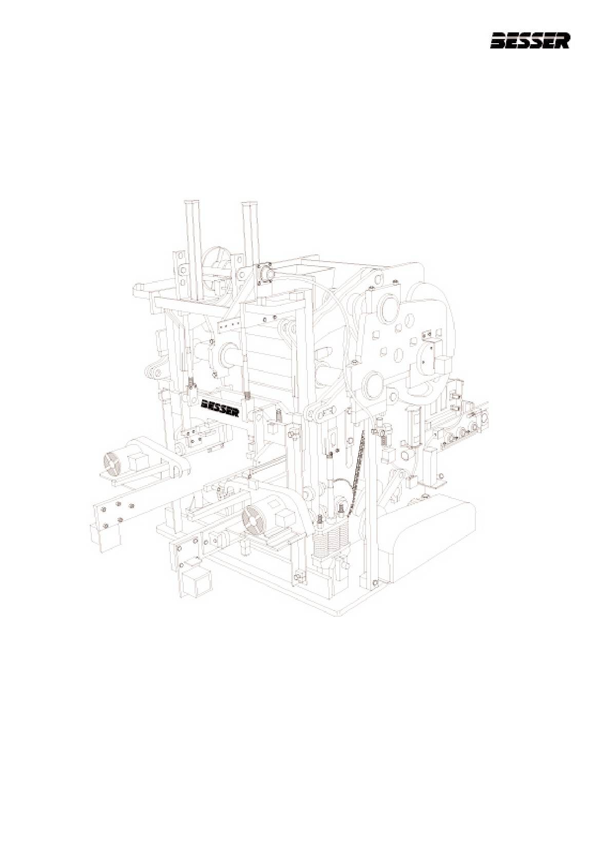
The directions left, right, front and rear, as mentioned throughout this manual are as seen when operator is
facing the machine as shown below.
REAR
LEFT
FRONT
RIGHT
2-2
466361F9710US F1 29OC99
SECTION 3
MACHINE DESCRIPTION
SECTION 3
MACHINE DESCRIPTION
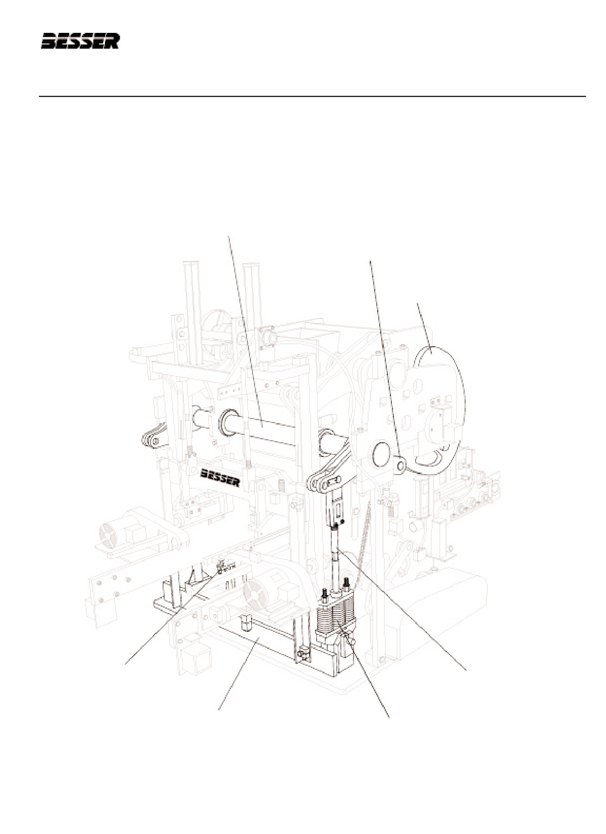
PALLET RECEIVER ASSEMBLY
PALLET RECEIVER SHAFT
PALLET RECEIVER ROLLER (1)
PALLET RECEIVER CAM (1)
RECEIVER RUBBERS
PALLET RECEIVER LINK (2)
PALLET RECEIVER FRAME
PALLET RECEIVER SPRING LINK ASSEMBLY (2)
466361F9710US F1 29OC99
3-1
SECTION 3
MACHINE DESCRIPTION
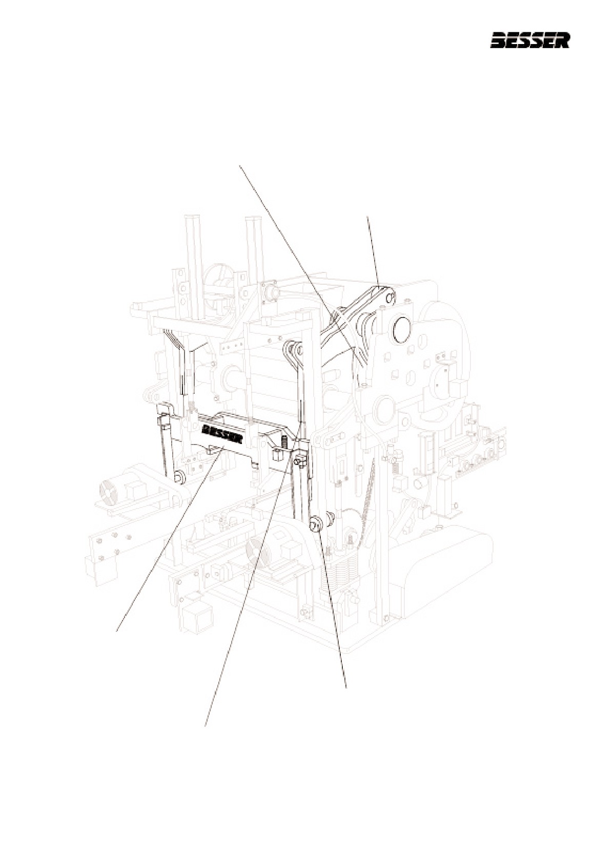
STRIPPER HEAD FRAME ASSEMBLY
STRIPPER HEAD CAM (2)
STRIPPER HEAD ROLLER (2)
STRIPPER HEAD FRAME
STRIPPER HEAD FRAME GUIDE LINER (4)
STRIPPER HEAD LINK (2)
3-2
466361F9710US F1 29OC99
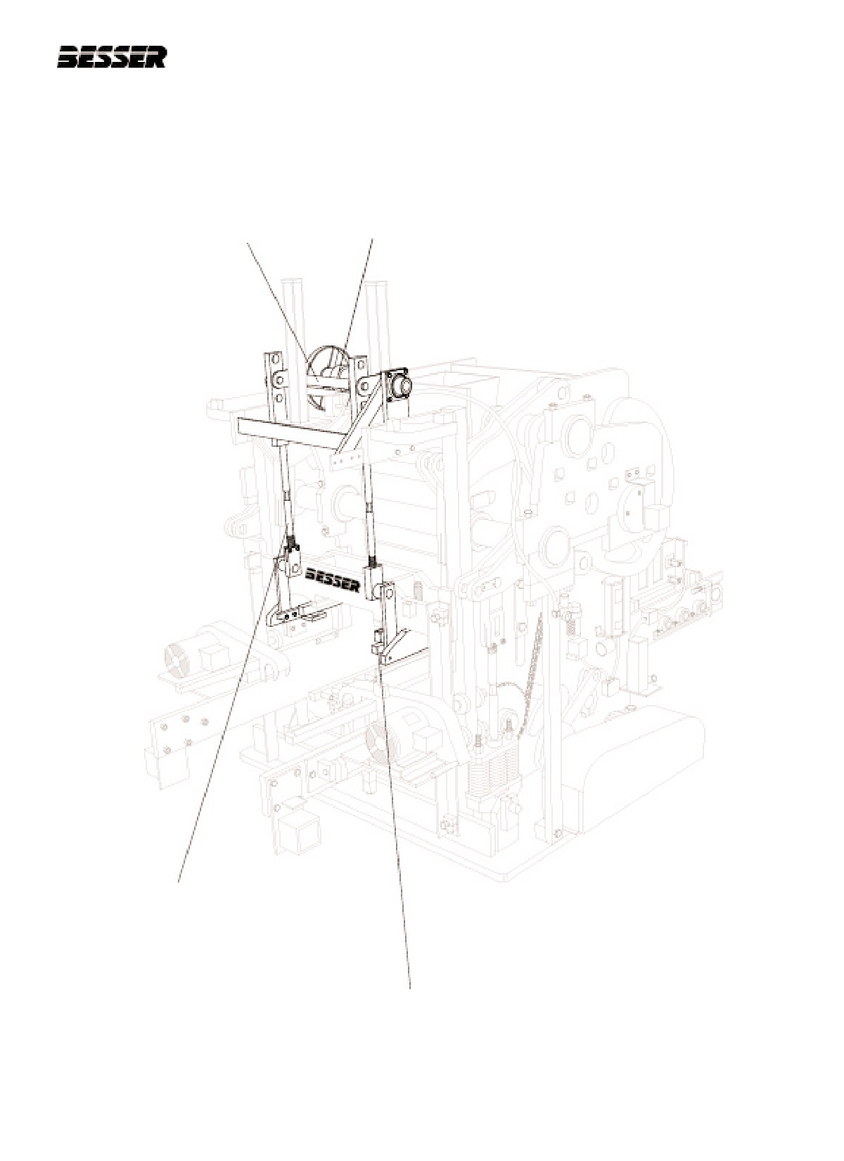
SECTION 3
MACHINE DESCRIPTION
AUTOFEED MECHANISM ASSEMBLY
AUTOFEED MECHANISM
AUTOFEED MECHANISM
DRIVE MOTOR
MAIN SHAFT
AUTOFEED MECHANISM
LINK (2)
FEED BOX TRACKS (2)
466361F9710US F1 29OC99
3-3
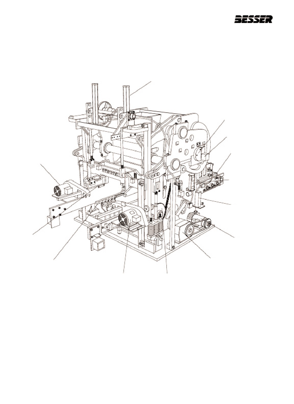
SECTION 3
MACHINE DESCRIPTION
GENERAL COMPONENTS
AIR COMPACTION CYLINDER (2)
MAIN SHAFT
ROTARY SENSOR
PALLET CHAIN
CONVEYOR
VIBRATING MOTOR
TRABON
LUBRICATION
PUMP
HYDRAULIC JACK
SYSTEM
MOLD THROAT (2)
BLOCK MOVING
MOTOR
BLOCK MOVING
BLOCK MOVING ARM (2)
REDUCER
VIBRATING MOTOR
PALLET TIMING
SPROCKET AND CHAIN
3-4
466361F9710US F1 29OC99
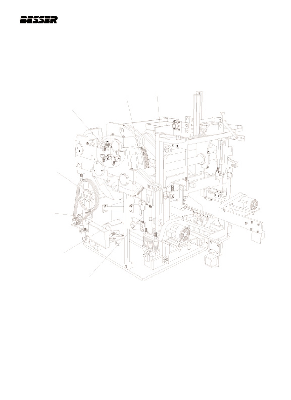
SECTION 3
MACHINE DESCRIPTION
GENERAL COMPONENTS
HOPPER
BULL GEAR
AIR FILTER / REGULATORS
MAIN DRIVE PULLEY
BESCODYNE
CLUTCH/BRAKE
DRIVE
MAIN DRIVE MOTOR
BLOCK RAISING
LINK ROD
466361F9710US F1 29OC99
3-5
SECTION 3
MACHINE DESCRIPTION
3-6
466361F9710US F1 29OC99
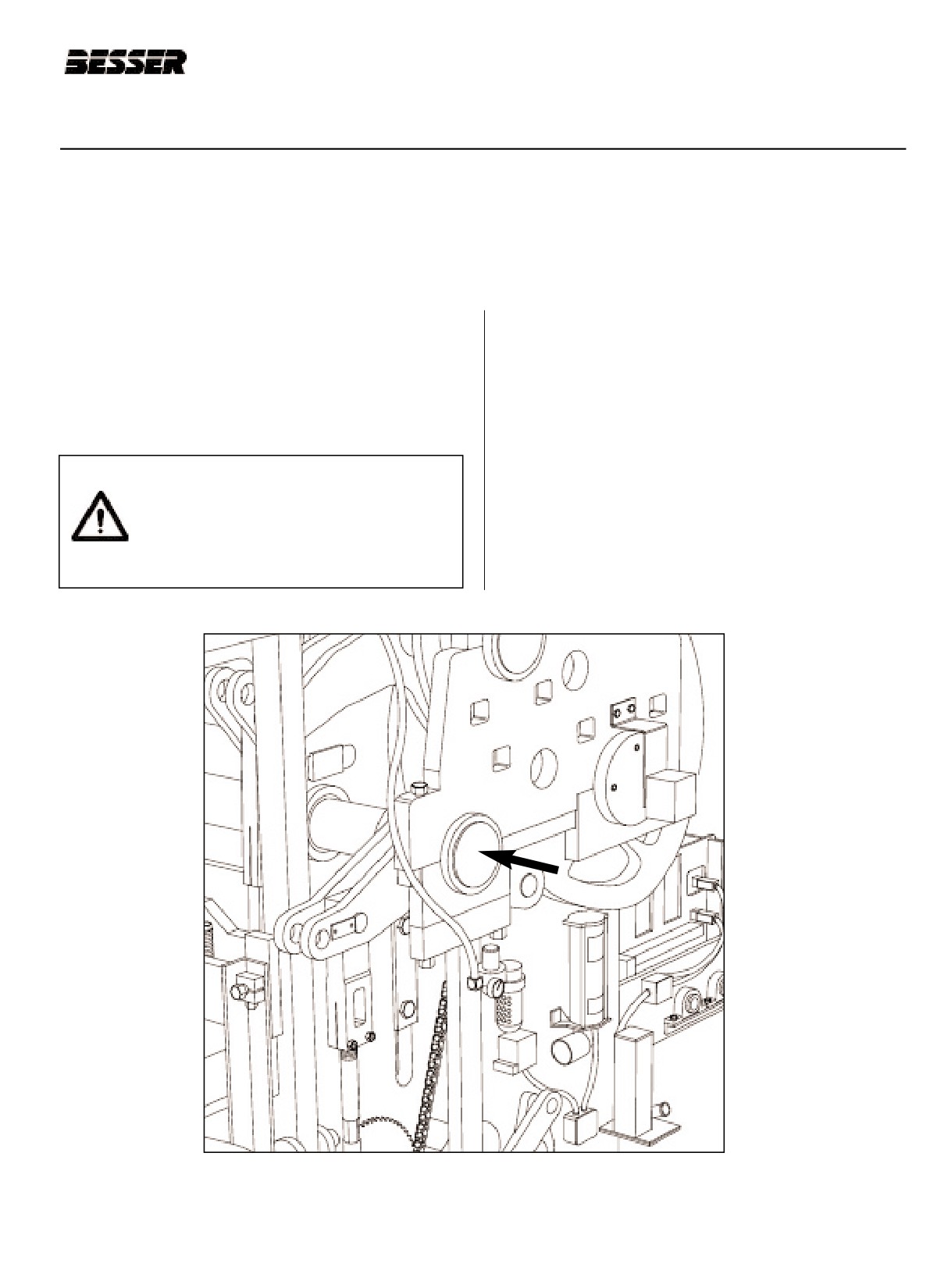
SECTION 4
MACHINE SET UP FOR 3 5/8" HIGH UNITS
SECTION 4
MACHINE SET UP FOR SPECIFIC MOLD
4.1
3 5/8" HIGH UNITS IN A 3 7/8" HIGH NON-RAMPED MOLD WITH A 14 3/16" HIGH
STRIPPER HEAD ASSEMBLY.
NOTE: THE FOLLOWING INSTRUCTIONS APPLY TO MACHINES WITHOUT QUICK CHANGE CAM INSERTS.
INITIAL CONDITION: No mold in the machine.
Note: Before adjusting or changing any pin positions,
lock-out and tag-out the machine and position
The following instructions will put the machine in
the machine in the stripped through position (pal-
approximate adjustment without the mold in the
let receiver frame resting on blocking and strip-
machine. Final adjustments will be necessary when
per head frame shock absorbers resting on
concrete units are produced. See sections 5 and 6 of
frame.) Then proceed with caution.
this manual.
4.1.1
The following items should be positioned as
CAUTION: Be sure to mechanically lock
shown in figures 4.1 and 4.2:
out the electrical panel when working on
the concrete product machine. Always
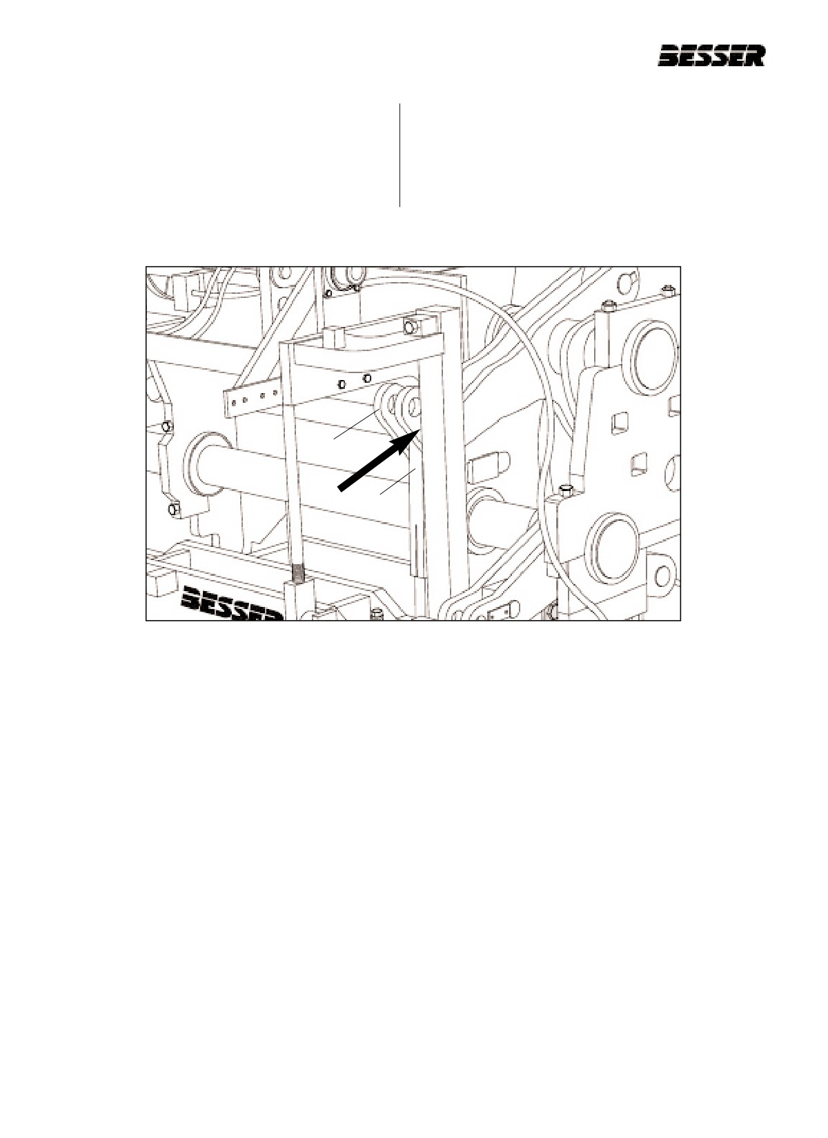
a. Pallet receiver shaft - position pins in inside holes
follow the lockout procedure listed in the
(short stroke)(see figure 4.1 below).
Safety section of this manual (see sec-
tion 1) !
Figure 4.1
PALLET RECEIVER SHAFT POSITION.
466361F9710US F1 29OC99
4-1
SECTION 4
MACHINE SET UP FOR 3 5/8" HIGH UNITS
Note: A short stroke is needed here since we are
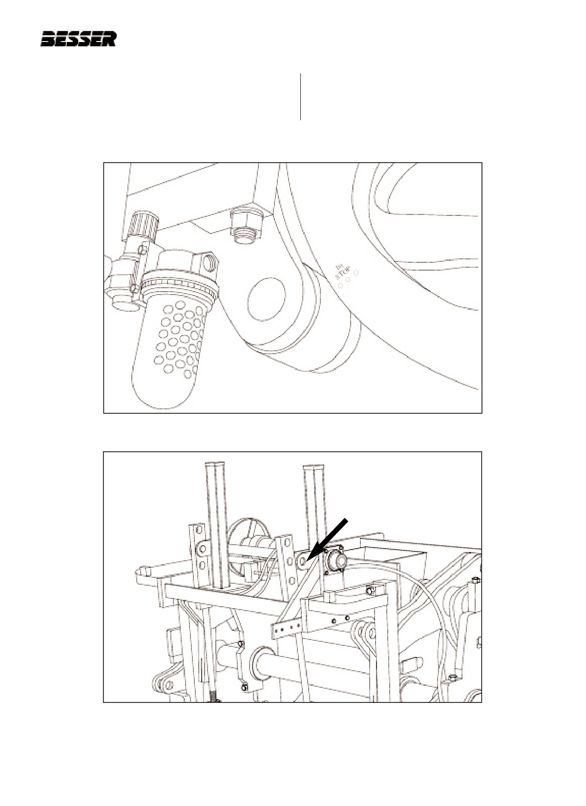
c. Stripper head links (B) - position pins in top holes
making low units.
(see figure 4.2). Adjust links to obtain approxi-
mately 7 3/4” [197mm] between link ends.
b. Stripper head shaft (A) - position pins in inside
holes (short stroke) (see figure 4.2).
A
B
Figure 4.2
STRIPPER HEAD SHAFT AND LINKS.
4-2
466361F9710US F1 29OC99
SECTION 4
MACHINE SET UP FOR 3 5/8" HIGH UNITS
4.1.2 Run machine to "first stop" (see figure 4.3.) Turn off
“First stop” is obtained when the punch marks on the
clutch and drive motor, and manually lower the aut-
right side outside cam are in line with the roller.
ofeed to its lowest position. Disconnect the two aut-
ofeed linkages at the top (see figure 4.4).
Figure 4.3
"FIRST STOP" (R.H. side of machine).
Figure 4.4
DISCONNECTING THE 2 AUTOFEED LINKAGES.
(1 of 2 disconnected here)
466361F9710US F1 29OC99
4-3
SECTION 4
MACHINE SET UP FOR 3 5/8" HIGH UNITS
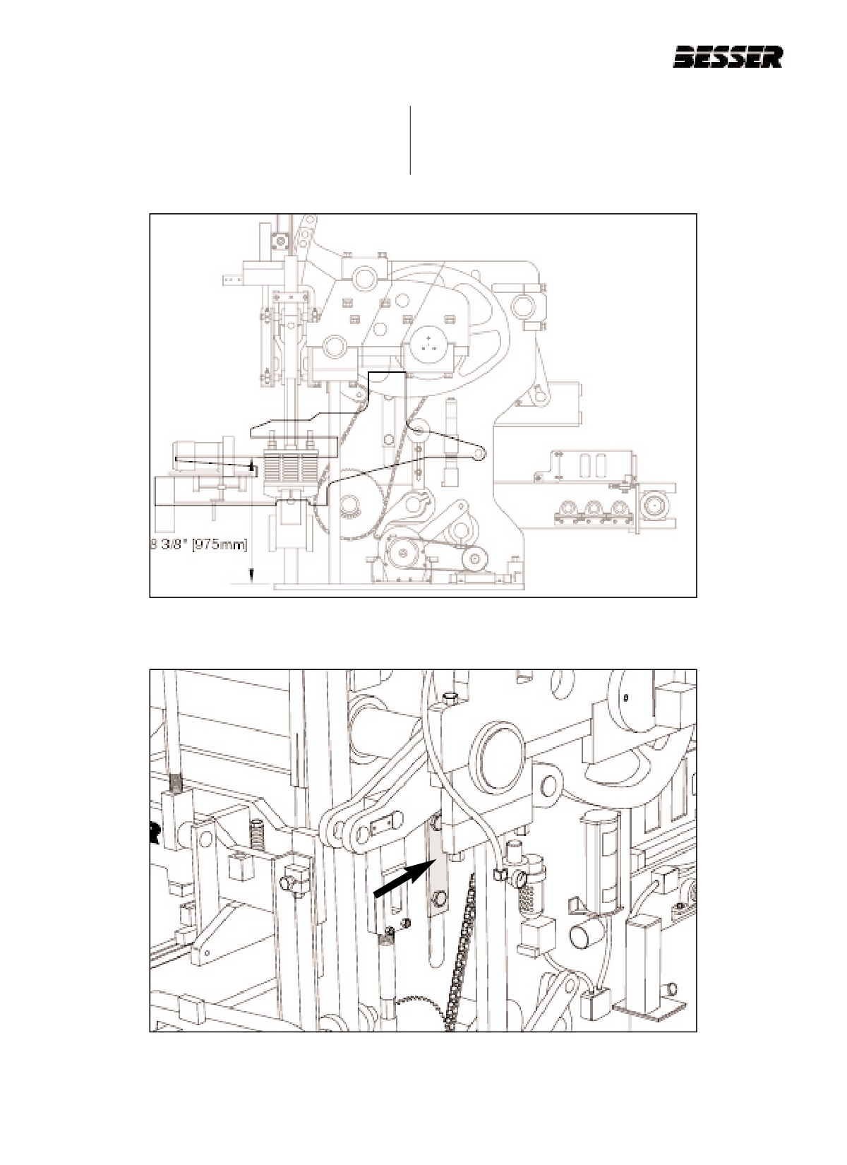
4.1.3 Adjust the inner frame so that the mold throat is
a. Loosen the "T" clamps on each side of machine that
38 3/8” [975mm] above the top on the base plate
secures machine side plate to mold throat plate.
(figure 4.5). 0.00” [0mm] of spacers required (no
(Figure 4.6)
spacers). To do so, follow these procedures.
Figure 4.5
INNER FRAME ADJUSTMENT.
Figure 4.6
LOOSEN "T" CLAMPS ON BOTH SIDES.
4-4
466361F9710US F1 29OC99
SECTION 4
MACHINE SET UP FOR 3 5/8" HIGH UNITS
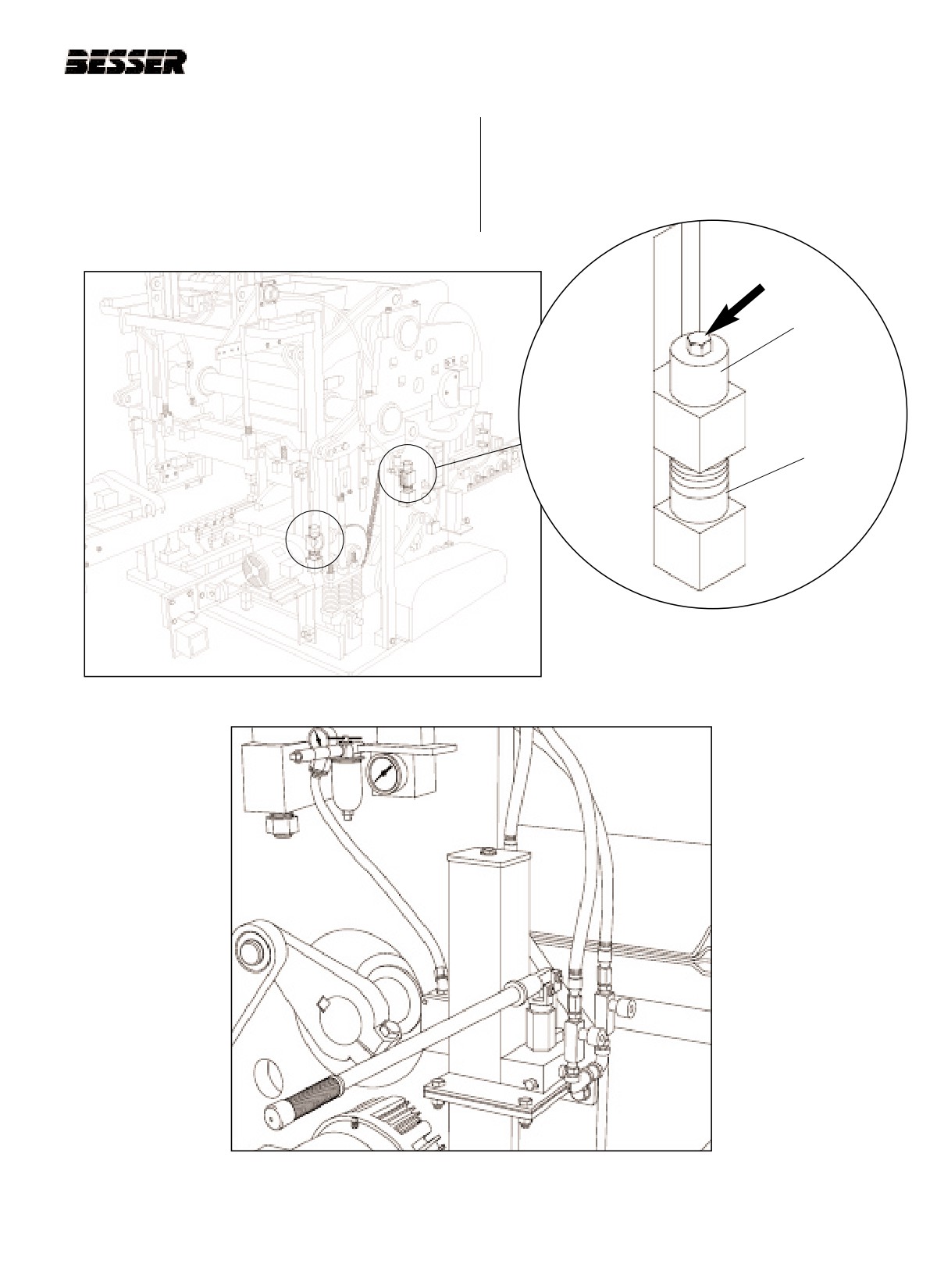
b. Loosen bolts at all 4 corners that secure mold throat
d. Allow hydraulic jack system to slowly lower entire
assembly (See figures 4.7 and 4.8). Remove top
mold throat assembly until supports contact at all 4
spacers.
corners.
c. Raise mold throat frame up by using hydraulic jack
system (figure 4.9) just high enough to allow all
lower spacers to be removed at all four corners.
TOP SPACERS
LOWER
SPACERS
(TO BE
REMOVED)
Figure 4.8
LOOSEN BOLTS
Figure 4.7
BOLTS AT ALL 4 CORNERS. (RIGHT SIDE SHOWN)
Figure 4.9
HYDRAULIC JACK SYSTEM.
466361F9710US F1 29OC99
4-5
SECTION 4
MACHINE SET UP FOR 3 5/8" HIGH UNITS
e. Store spacers on bottom side of bolt for front bolts
and left hand rear bolt. For right hand rear bolt store
spacers on top. Tighten bolts at all 4 corners that
secure mold throat plate spacers (see figure 4.10).
f. Tighten "T" clamps on each side of machine that
secures machine side plate to mold throat plate.
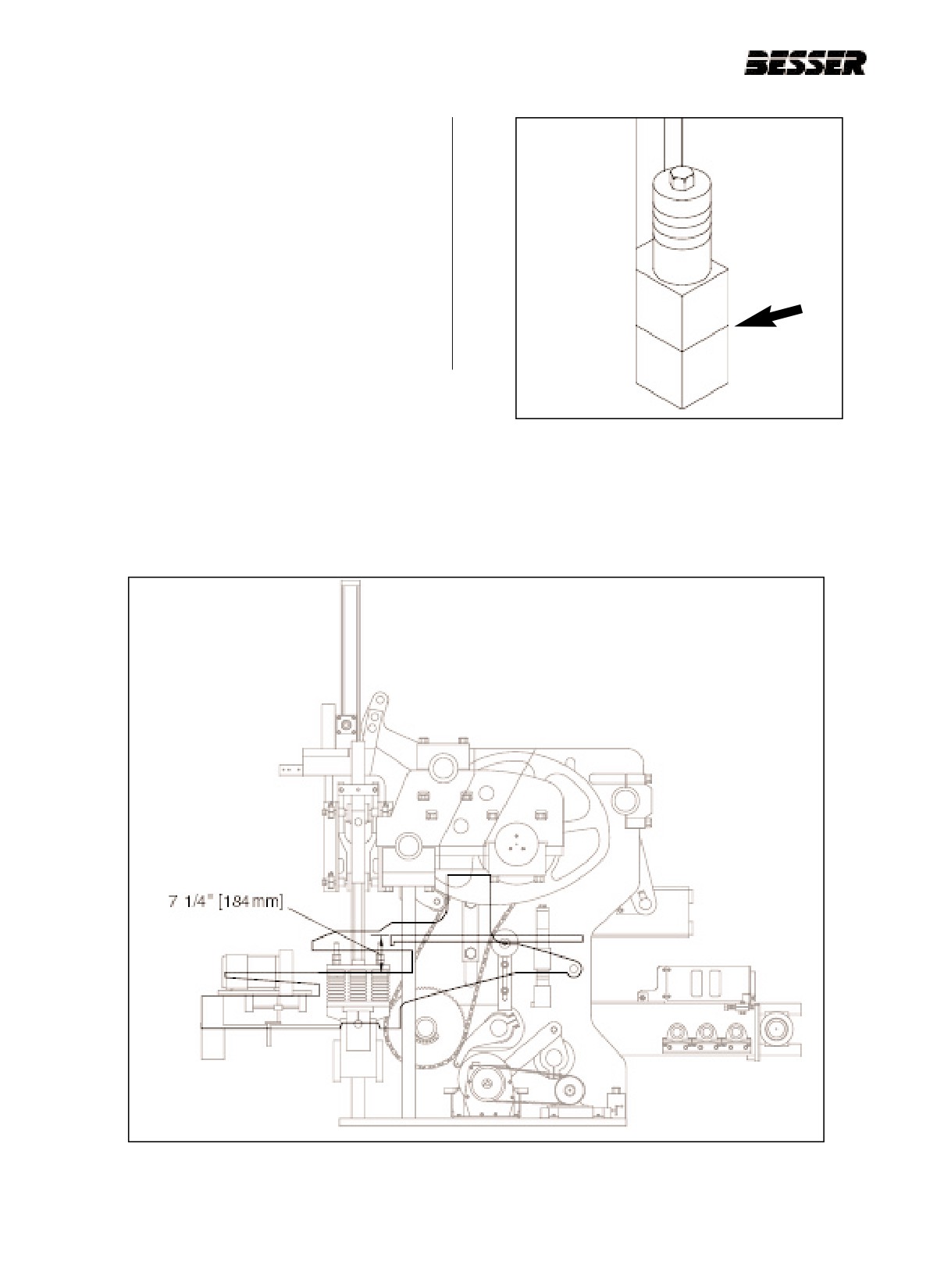
4.1.4 Reconnect autofeed linkage and adjust so that the
top of the apron plate is 7 1/4” [184mm] above the
mold throat at the lowest position of the autofeed
(see figure 4.11). To adjust, lower or raise the aut-
ofeed until apron plate is in correct position.
Figure 4.10
NO SPACERS
Figure 4.11
APRON PLATE ABOVE MOLD THROAT ADJUSTMENT.
4-6
466361F9710US F1 29OC99
SECTION 4
MACHINE SET UP FOR 3 5/8" HIGH UNITS
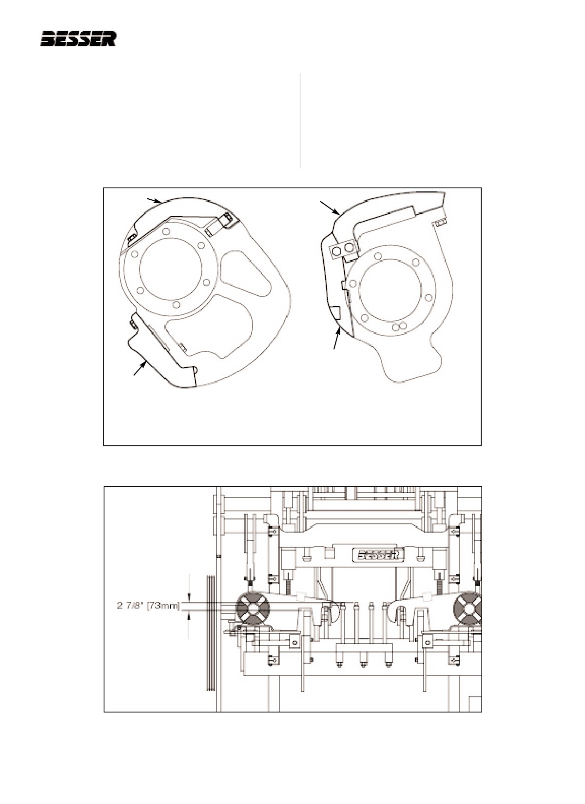
4.1.5 Install stripping cam insert # 320209 on each side of
Use pallet receiver link rod on both sides of pallet
the machine and one stripper head raising cam
receiver to lower or raise the rubbers as shown in
insert # 323058 on the right side of the machine
figure 5.14 of page 5.9.
(see figure 4.12).
4.1.6 Adjust the pallet receiver frame so that the pallet
receiver rubbers are 2 7/8” [73mm] above the mold
throat (see figure 4.13).
RAISING
STRIPPING
INSERT
INSERT
LOWERING
INSERT
LOWERING
INSERT
STRIPPER HEAD RAISING AND
LOWERING CAM #323058:
STRIPPING CAM #320209:
CENTER CAM ON RIGHT HAND SIDE
INNER MOST CAM ON BOTH SIDES
Figure 4.12
CAM INSERTS.
Figure 4.13
PALLET RECEIVER RUBBERS POSITION.
466361F9710US F1 29OC99
4-7

SECTION 4
MACHINE SET UP FOR 3 5/8" HIGH UNITS
4.1.7 Adjust the upper height stops so that 7 15/16"
4.1.8 Adjust the shock absorbers to a dimension 11
[202mm] extends past the bottom of the castings as
15/16" [303mm] (represented by "A" in figure 4.15)
shown on figure 4.14.
from the bottom of the clamp blocks to the bottom of
the rubber pads.
Figure 4.14
UPPER HEIGHT STOPS.
Figure 4.15
SHOCK ABSORBERS ADJUSTMENT.
4-8
466361F9710US F1 29OC99
SECTION 4
MACHINE SET UP FOR 3 5/8" HIGH UNITS
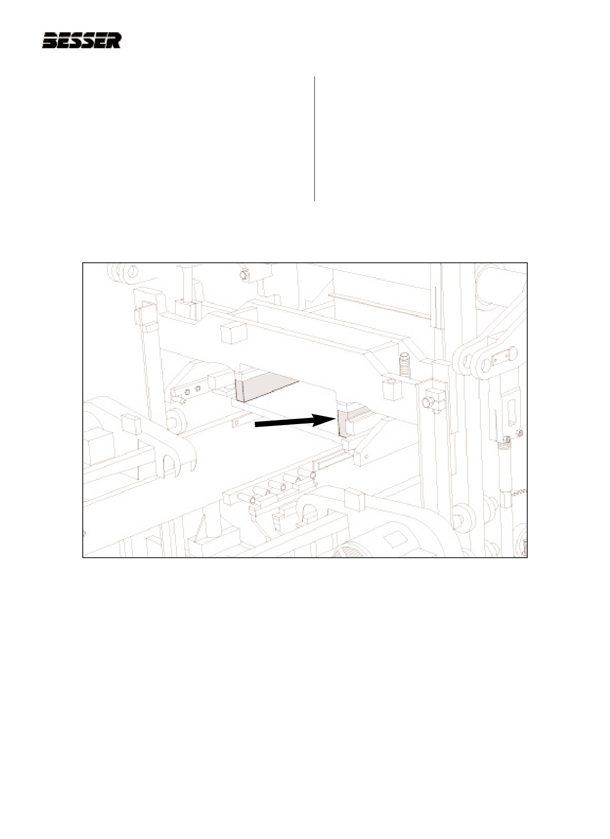
4.1.9 The DYNAPAC is now ready for the installation of
the mold assembly. Follow the directions for
installing an attachment in section 5 of this manual.
When installing the stripper head, insert 4 3/8"
[111mm] of blocking in addition to the 1 1/2"
[38mm] blocks already affixed to the stripper head
frame (figure 4.16). The above blocking assumes a
stripper head height of 14 3/16" [360 mm] from the
top of the head plate to the bottom of the shoes.
Figure 4.16
4 3/8" [111mm] BLOCKING UNDER STRIPPER HEAD FRAME.
466361F9710US F1 29OC99
4-9
//////////////////////////////////////////