BESSER DYNAPAC 3 AT A TIME (466361F9710US). OPERATION / MAINTENANCE MANUAL - page 2
SECTION 4
MACHINE SET UP FOR 3 5/8" HIGH UNITS
4-10
466361F9710US F1 29OC99
SECTION 4
MACHINE SET UP FOR 5 5/8" HIGH UNITS
4.2
5 5/8" HIGH UNITS IN A 6 3/16" HIGH NON-RAMPED MOLD WITH A 14 3/16" HIGH
STRIPPER HEAD ASSEMBLY.
NOTE: THE FOLLOWING INSTRUCTIONS APPLY TO MACHINES WITHOUT QUICK CHANGE CAM INSERTS.
INITIAL CONDITION: No mold in the machine.
Note: Before adjusting or changing any pin posi t i o n s ,
lock-out and tag-out the machine and position
The following instructions will put the machine in
the machine in the stripped through position (pal-
approximate adjustment without the mold in the
let receiver frame resting on blocking and strip-
machine. Final adjustments will be necessary when
per head frame shock absorbers resting on
concrete units are produced. See sections 5 and 6 of
frame.) Then proceed with caution.
this manual.
4.2.1
The following items should be positioned as
shown in figure 4.17 and 4.18:
CAUTION: Be sure to mechanically lock
out the electrical panel when working on
a. Pallet receiver shaft - position pins in inside holes
the concrete product machine. Always
(short stroke)(see figure 4.17 below).
follow the lockout procedure listed in the
Safety section of this manual (see sec-
Note: A short stroke is needed here since we are
tion 1) !
making low units.
Figure 4.17
PALLET RECEIVER SHAFT POSITION.
466361F9710US F1 29OC99
4-11
SECTION 4
MACHINE SET UP FOR 5 5/8" HIGH UNITS OPERATION/MAINTENANCE MANUAL
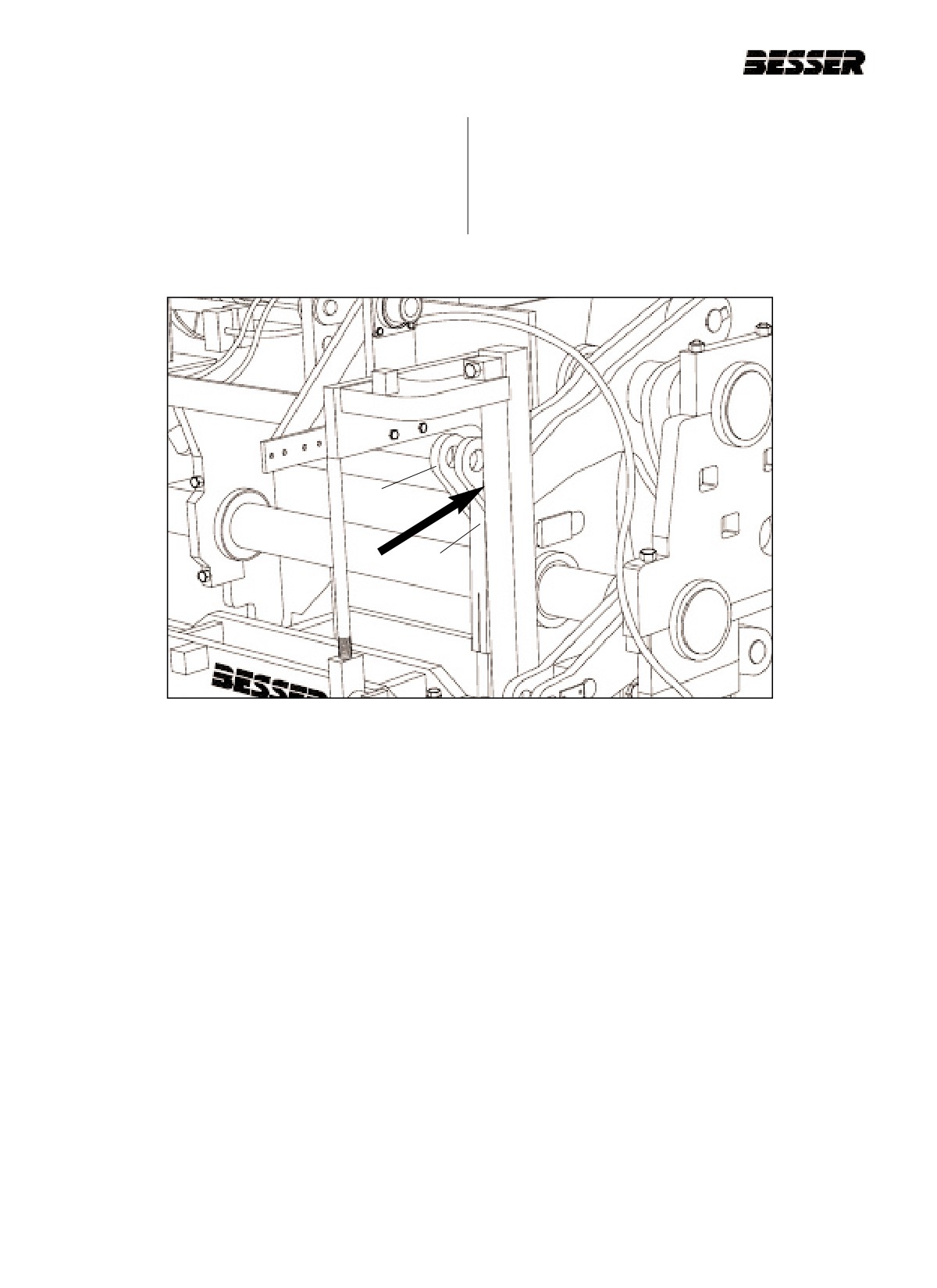
b. Stripper head shaft (A)- position pins in inside
holes (short stroke) (see figure 4.18).
c. Stripper head links (B)- position pins in top holes.
Adjust links to obtain approximately 7 3/4” [197
mm] (see figure 4.18) between link ends.
A
B
Figure 4.18
STRIPPER HEAD SHAFT AND LINKS.
4-12
466361F9710US F1 29OC99
SECTION 4
MACHINE SET UP FOR 5 5/8" HIGH UNITS
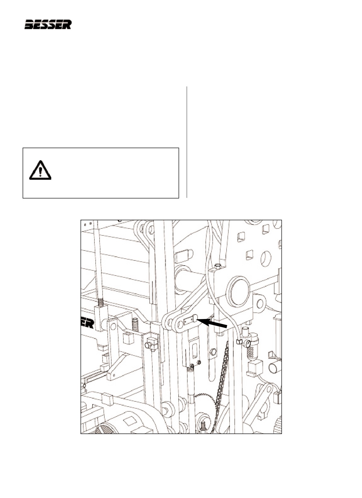
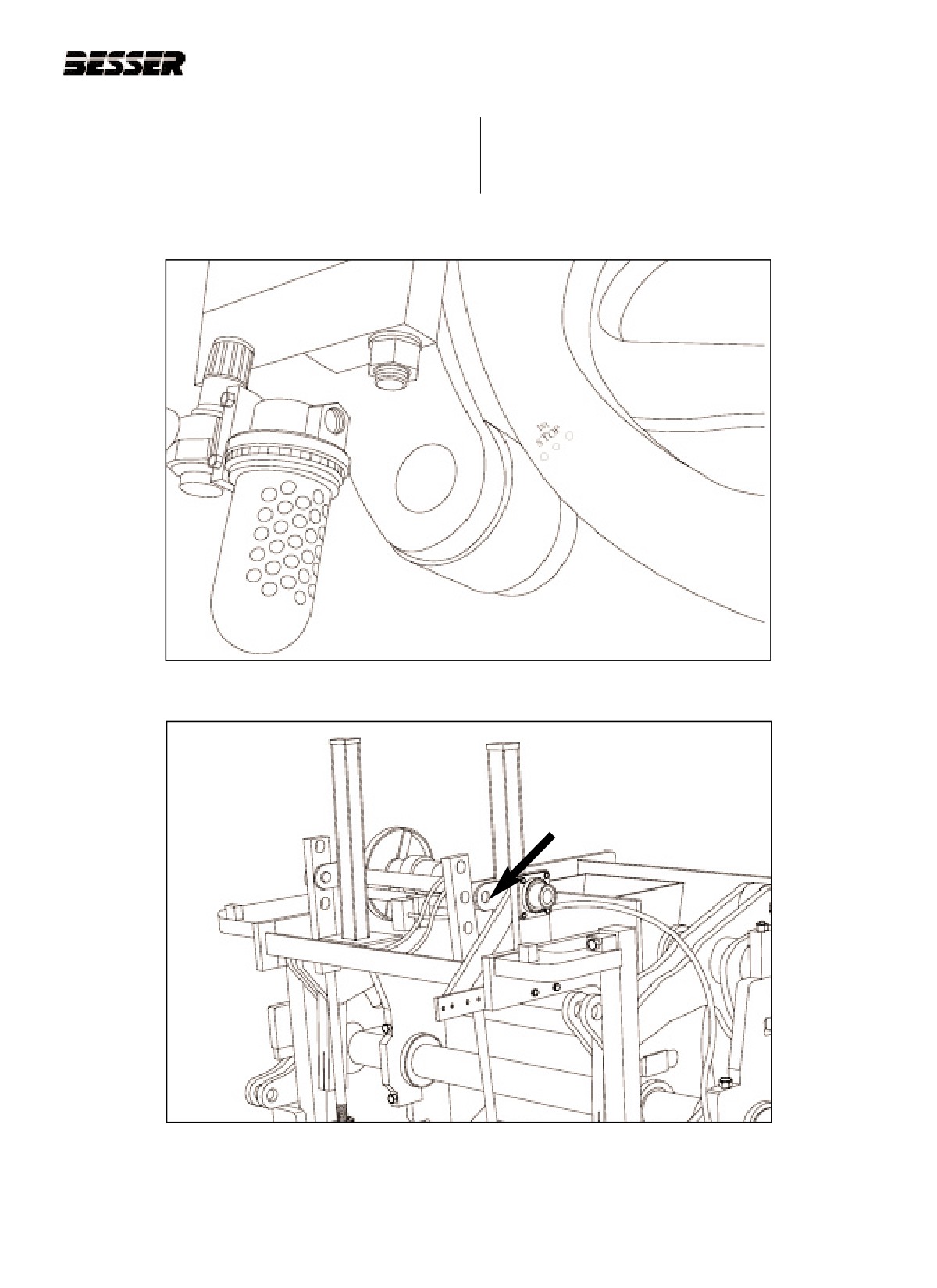
4.2.2 Run machine to "first stop" (see figure 4.19.) Turn off
“First stop” is obtained when the punch marks on the
clutch and drive motor, and manually lower the aut-
right side outside cam are in line with the roller.
ofeed to its lowest position. Disconnect the two aut-
ofeed linkages at the top (see figure 4.20).
Figure 4.19
"FIRST STOP". (R.H. side of machine)
Figure 4.20
DISCONNECTING THE AUTOFEED LINKAGES.
(1 of 2 disconnected here)
466361F9710US F1 29OC99
4-13
SECTION 4
MACHINE SET UP FOR 5 5/8" HIGH UNITS OPERATION/MAINTENANCE MANUAL
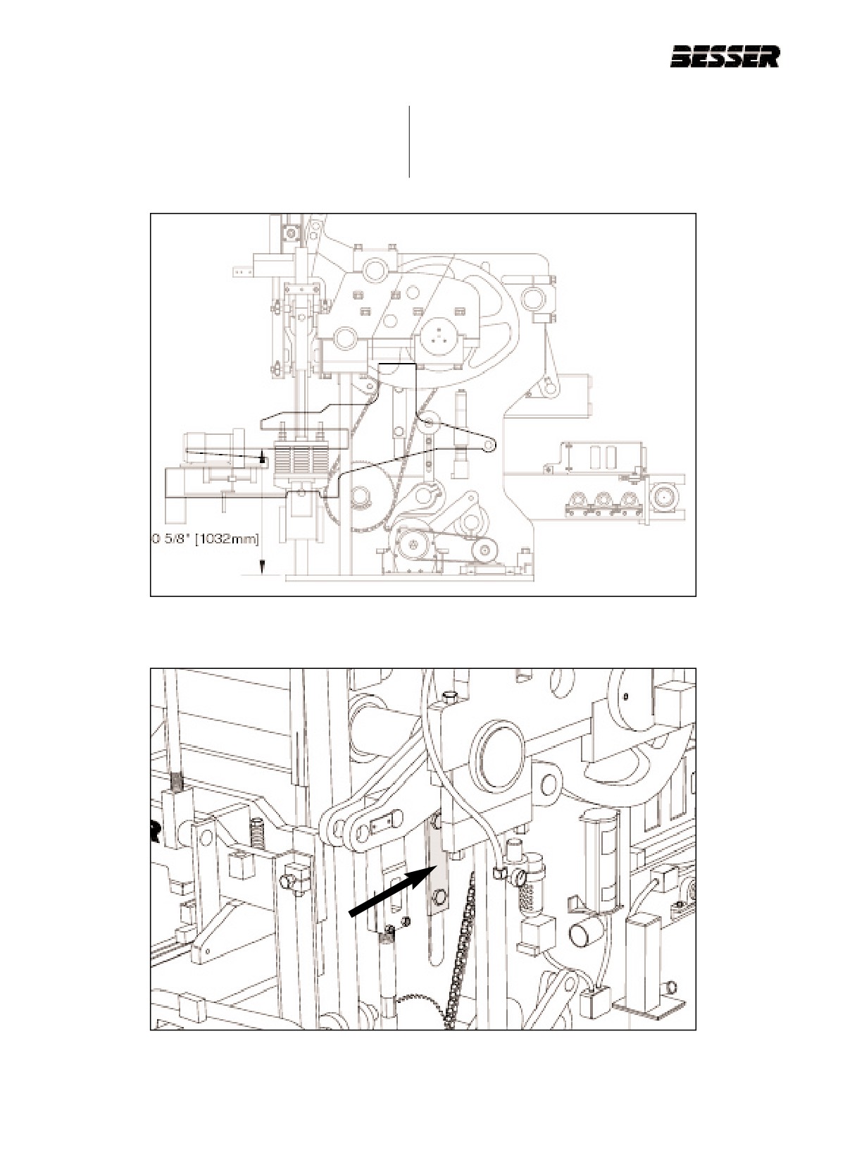
4.2.3 Adjust the inner frame so that the mold throat is
a. Loosen the "T" clamps on each side of machine that
40 5/8” [1032mm] above the top on the base
secures machine side plate to mold throat plate (fig-
plate (figure 4.21). 2 1/4” [57mm] of spacers are
ure 4.22).
required. To do so, follow these procedures.
Figure 4.21
INNER FRAME ADJUSTMENT.
Figure 4.22
LOOSEN "T" CLAMPS ON BOTH SIDES.
4-14
466361F9710US F1 29OC99
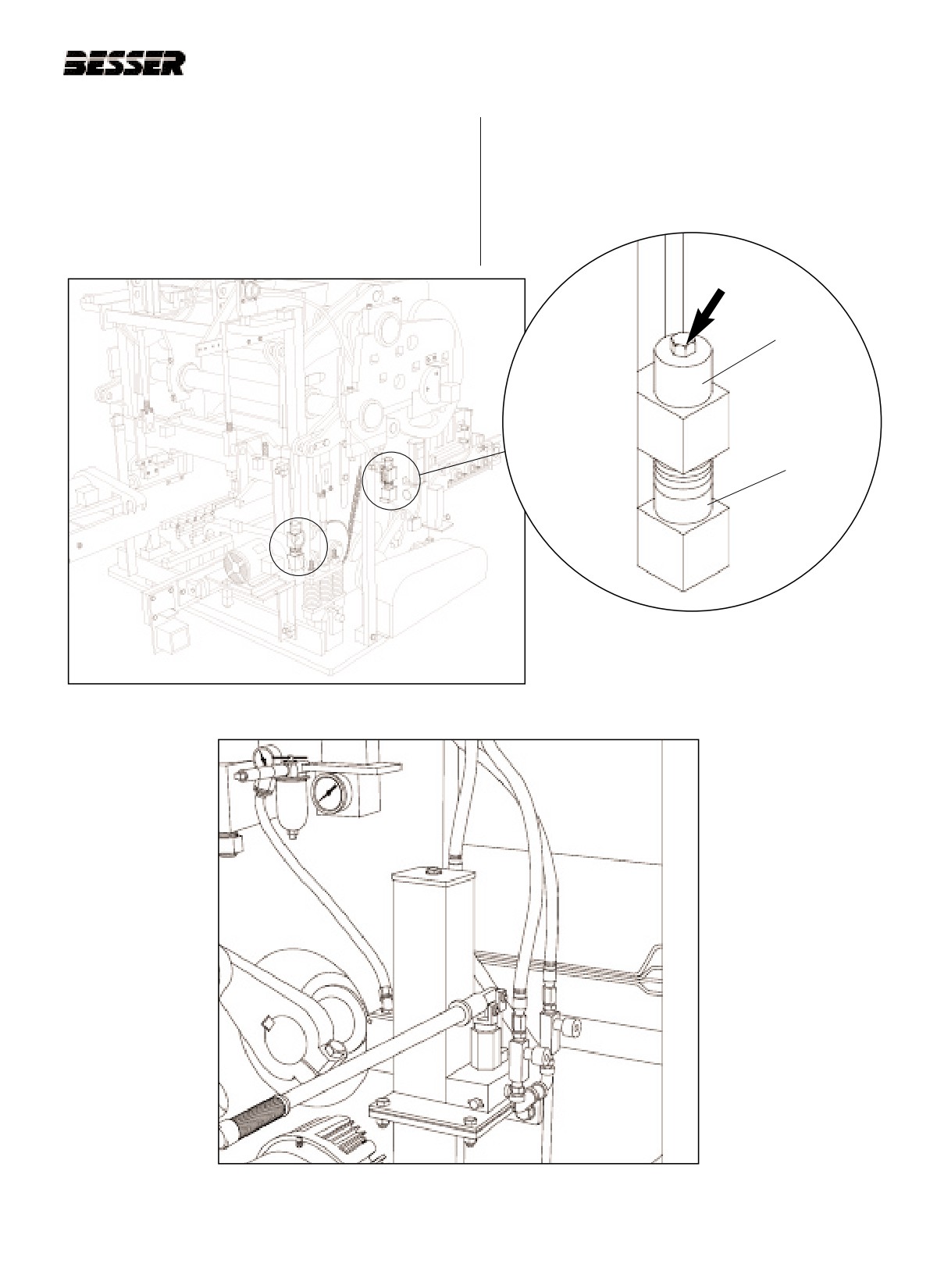
SECTION 4
MACHINE SET UP FOR 5 5/8" HIGH UNITS
b. Loosen bolts at all 4 corners that secure mold throat
d. Allow hydraulic jack system to slowly lower entire
assembly (see figures 4.23 and 4.24). Remove top
mold throat assembly until supports contact at all 4
spacers.
corners.
c. Raise mold throat frame up by using hydraulic jack
system (figure 4.25) just high enough to allow all
lower spacers to be added or removed at all four
corners.
TOP SPACERS
LOWER
SPACERS
(TO BE
REMOVED)
Figure 4.24
LOOSEN BOLTS
Figure 4.23
BOLTS AT ALL 4 CORNERS. (RIGHT SIDE SHOWN)
Figure 4.25
HYDRAULIC JACK SYSTEM.
466361F9710US F1 29OC99
4-15
SECTION 4
MACHINE SET UP FOR 5 5/8" HIGH UNITS OPERATION/MAINTENANCE MANUAL
e. Store spacers on bottom side of bolt for front bolts
and left hand rear bolt. For right hand rear bolt store
spacers on top. Tighten bolts at all 4 corners that
secure mold throat plate spacers (see figure 4.26).
f. Tighten "T" clamps on each side of machine that
secures machine side plate to mold throat plate.
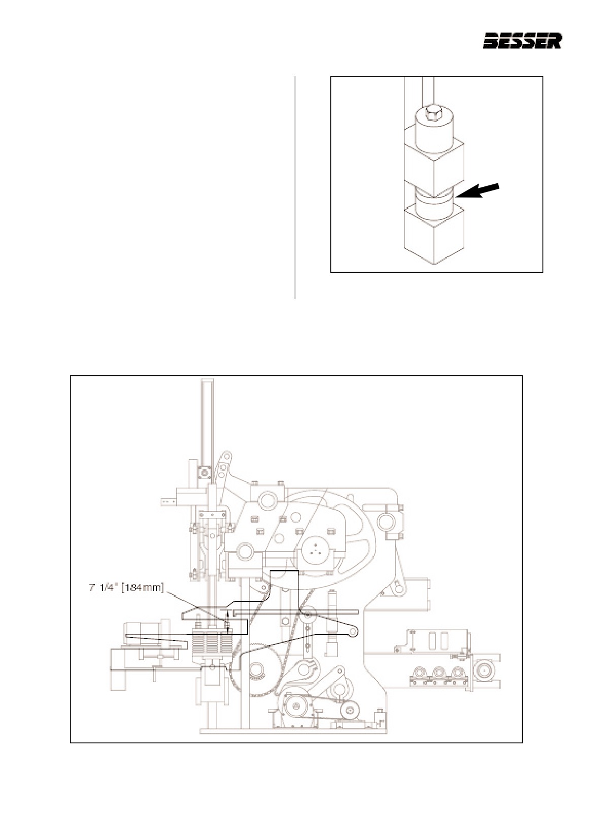
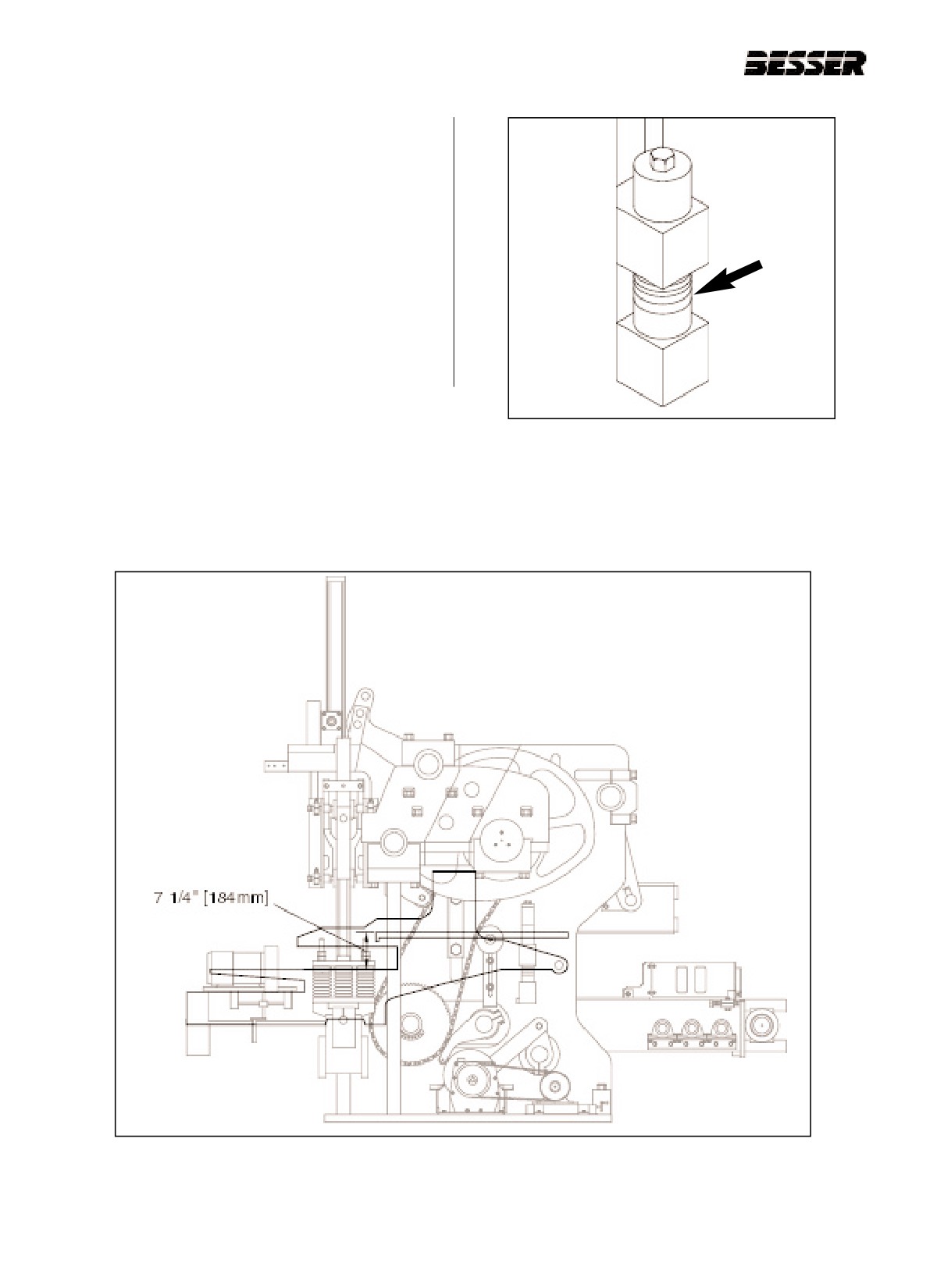
4.2.4 Reconnect autofeed linkage and adjust so that
the top of the apron plate is 7.25” [184 mm]
above the mold throat at the lowest position of the
autofeed (see figure 4.27). To adjust, lower or
raise the autofeed until apron plate is in correct
position.
Figure
4.26 2 1/4” [57mm] OF SPACERS.
Figure 4.27
APRON PLATE ABOVE MOLD THROAT ADJUSTMENT.
4-16
466361F9710US F1 29OC99
SECTION 4
MACHINE SET UP FOR 5 5/8" HIGH UNITS
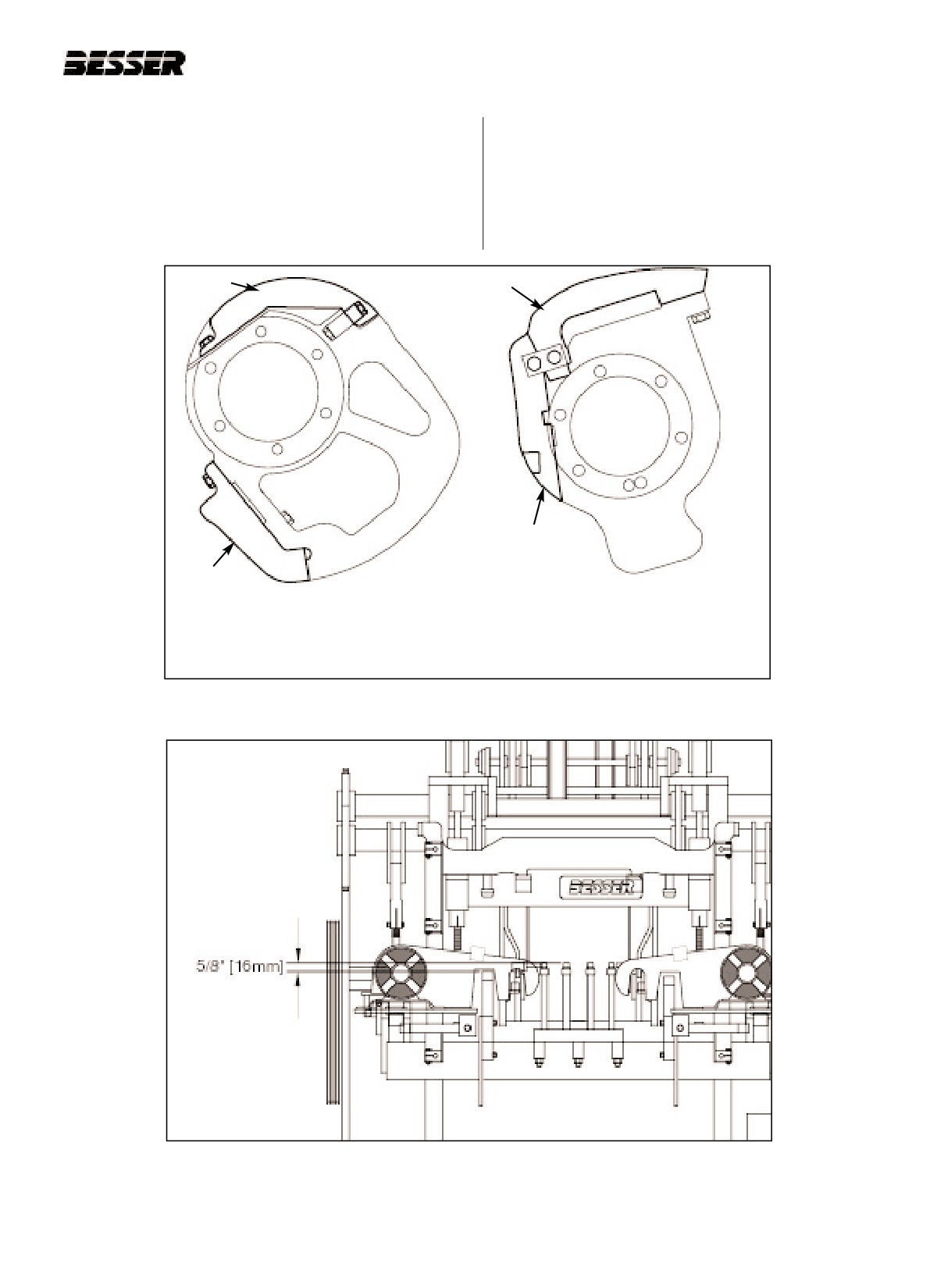
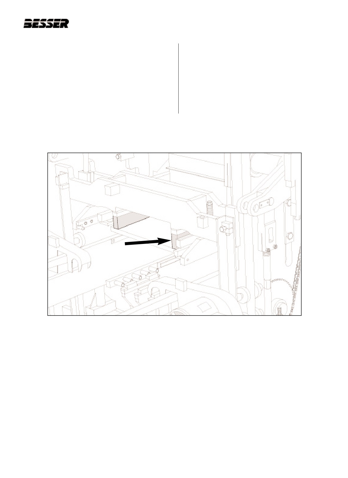
4.2.5 Install stripping cam insert # 371731 on each side
4.2.6 Adjust the pallet receiver frame so that the pallet
of the machine and one stripper head raising cam
receiver rubbers are 5/8” [16mm] above the mold
insert # 371729 on the right side of the machine
throat (see figure 4.29).
(see figure 4.28).
Use pallet receiver link rod on both side of pallet
receiver to lower or raise the rubbers as shown in
figure 5.14 of page 5.9.
RAISING
STRIPPING
INSERT
INSERT
LOWERING
INSERT
LOWERING
INSERT
STRIPPER HEAD RAISING AND
LOWERING CAM #371729:
STRIPPING CAM #371731:
CENTER CAM RIGHT HAND SIDE
INNER MOST CAM ON BOTH SIDES
Figure 4.28
CAM INSERTS.
Figure 4.29
PALLET RECEIVER RUBBERS POSITION.
466361F9710US F1 29OC99
4-17
SECTION 4
MACHINE SET UP FOR 5 5/8" HIGH UNITS OPERATION/MAINTENANCE MANUAL
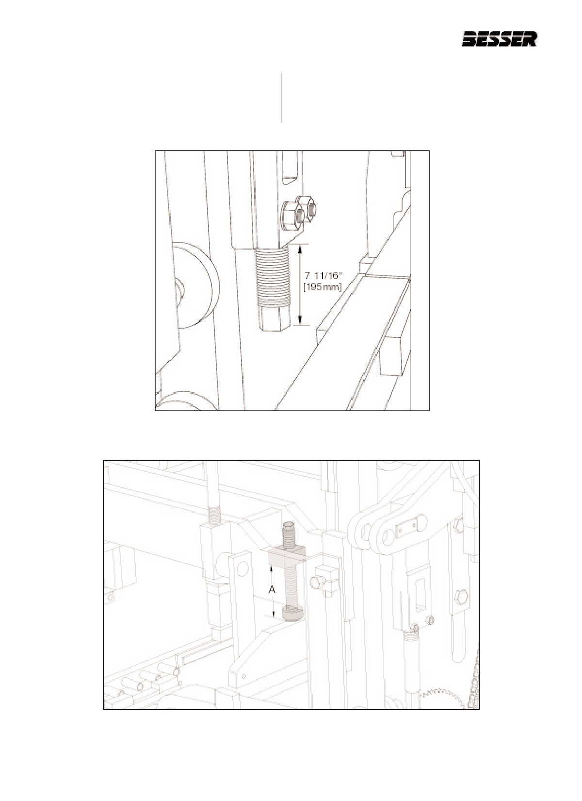
4.2.7 Adjust the upper height stops so that 7 11/16"
4.2.8 Adjust the shock absorbers to a dimension 7
[195mm] extend past the bottom of the castings
7/16" [189mm] (represented by "A" in figure
as shown on figure 4.30.
4.31) from the bottom of the clamp blocks to the
bottom of the rubber pads.
Figure 4.30
UPPER HEIGHT STOPS.
Figure 4.31
SHOCK ABSORBERS ADJUSTMENT.
4-18
466361F9710US F1 29OC99
SECTION 4
MACHINE SET UP FOR 5 5/8" HIGH UNITS
4.2.9 The DYNAPAC is now ready for the installation of
the mold assembly. Follow the directions for
installing an attachment in section 5 of this manu-
al. When installing the stripper head, insert 2 1/8"
[54mm] of blocking in addition to the 1 1/2” [38
mm] blocks already affixed to the stripper head
frame (figure 4.32). The above blocking assumes
a stripper head height of 14 3/16" [360mm] from
the top of the head plate to the bottom of the
shoes.
Figure 4.32
2 1/8” [54mm] BLOCKING UNDER STRIPPER HEAD FRAME.
466361F9710US F1 29OC99
4-19
SECTION 4
MACHINE SET UP FOR 5 5/8" HIGH UNITS OPERATION/MAINTENANCE MANUAL
4-20
466361F9710US F1 29OC99
SECTION 4
MACHINE SET UP FOR 80MM HIGH UNITS
4.3
80 MM HIGH UNITS IN A 86 MM HIGH NON-RAMPED MOLD WITH A 360 MM HIGH
STRIPPER HEAD ASSEMBLY.
NOTE: THE FOLLOWING INSTRUCTIONS APPLY TO MACHINES WITHOUT QUICK CHANGE CAM INSERTS.
INITIAL CONDITION: No mold in the machine.
Note: Before adjusting or changing any pin positions,
lock-out and tag-out the machine and position
The following instructions will put the machine in
the machine in the stripped through position (pal-
approximate adjustment without the mold in the
let receiver frame resting on blocking and strip-
machine. Final adjustments will be necessary when
per head frame shock absorbers resting on
concrete units are produced. See sections 5 and 6 of
frame.) Then proceed with caution.
this manual.
4.3.1
Run machine to "first stop" (see figure 4.33).
CAUTION: Be sure to mechanically lock
Turn off clutch and drive motor and manually
out the electrical panel when working on
lower the autofeed to its lowest position.
the concrete product machine. Always
Disconnect the two autofeed linkages at the top
follow the lockout procedure listed in the
(see figure 4.34).
Safety section of this manual (see sec-
tion 1) !
“First stop” is obtained when the punch marks on the
right side outside cam are in line with the roller.
Figure 4.33
"FIRST STOP" (R.H. side of machine).
Figure 4.34
DISCONNECTING THE AUTOFEED LINKAGES.
(1 of 2 disconnected here)
466361F9710US F1 29OC99
4-21
SECTION 4
MACHINE SET UP FOR 80MM HIGH UNITS OPERATION/MAINTENANCE MANUAL
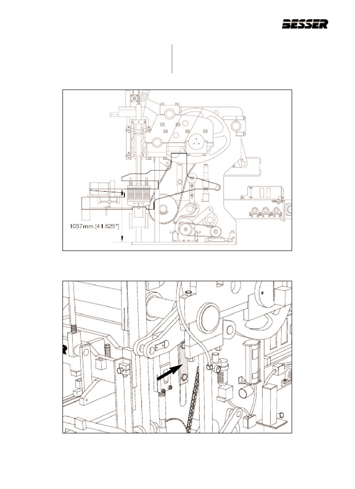
4.3.2 Adjust the inner frame so that the mold throat is
a. Loosen the "T" clamps on each side of machine that
1057mm [41.625”] above the top on the base
secures machine side plate to mold throat plate (fig-
plate (figure 4.35). 83mm [3.25”] of spacers are
ure 4.36).
required. To do so, follow these procedures.
Figure 4.35
INNER FRAME ADJUSTMENT.
Figure 4.36
LOOSEN "T" CLAMPS ON BOTH SIDES.
4-22
466361F9710US F1 29OC99
SECTION 4
MACHINE SET UP FOR 80MM HIGH UNITS
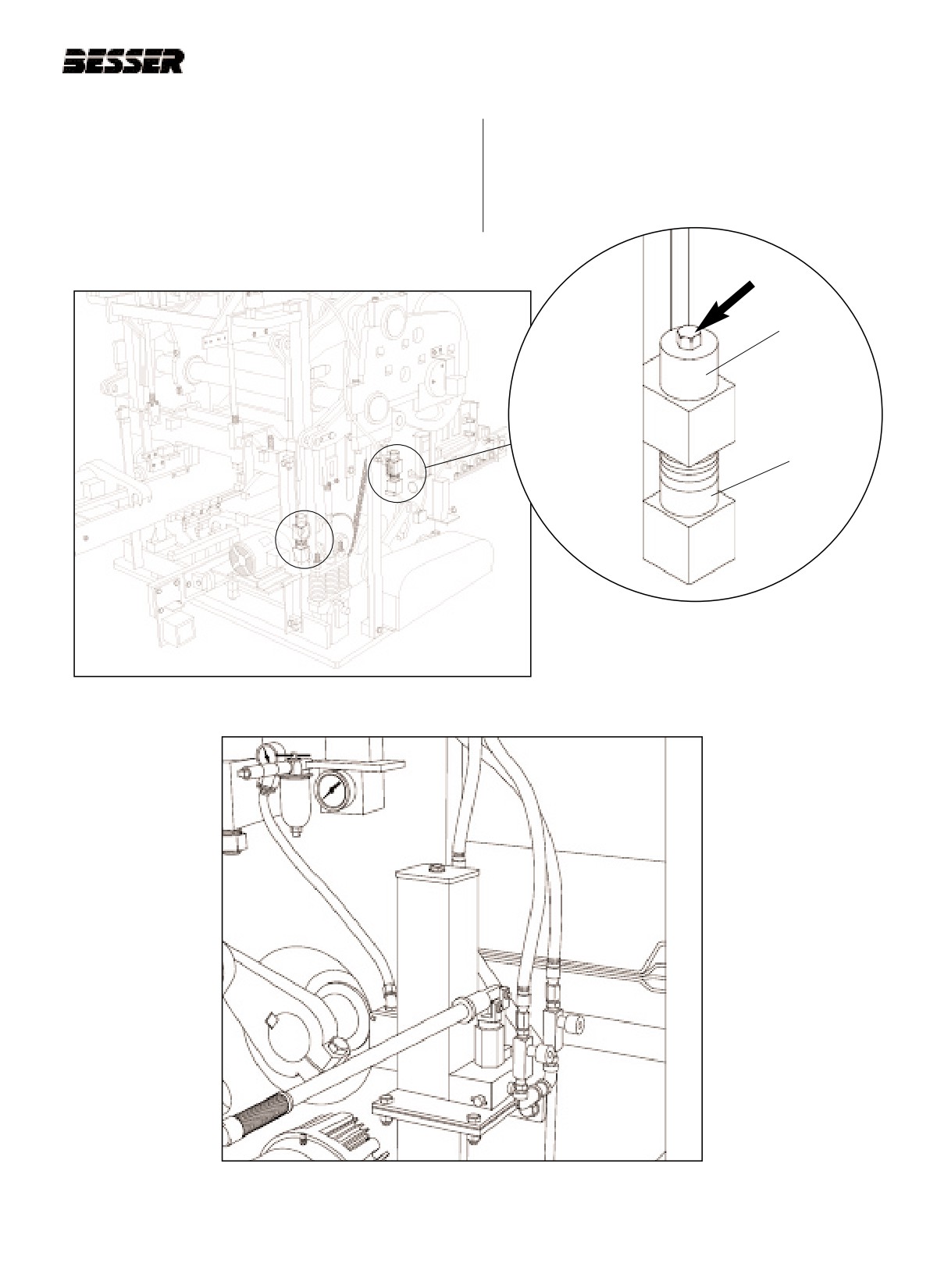
b. Loosen bolts at all 4 corners that secure mold throat
d. Allow hydraulic jack system to slowly lower entire
assembly (See figure 4.37 and 4.38). Remove top
mold throat assembly until supports contact at all 4
spacers.
corners.
c. Raise mold throat frame up by using hydraulic jack
system (figure 4.39) just high enough to allow all
lower spacers to be removed or added at all four
corners.
TOP SPACERS
LOWER
SPACERS
(TO BE
REMOVED)
Figure 4.38
LOOSEN BOLTS
Figure 4.37
BOLTS AT ALL 4 CORNERS. (RIGHT SIDE SHOWN)
Figure 4.39
HYDRAULIC JACK SYSTEM.
466361F9710US F1 29OC99
4-23
SECTION 4
MACHINE SET UP FOR 80MM HIGH UNITS OPERATION/MAINTENANCE MANUAL
e. Store spacers on bottom side of bolt for front bolts
and left hand rear bolt. For right hand rear bolt store
spacers on top. Tighten bolts at all 4 corners that
secure mold throat plate spacers. (See figure 4.40).
f. Tighten "T" clamps on each side of machine that
secures machine side plate to mold throat plate.
4.3.3 Reconnect autofeed linkage and adjust so that
the top of the apron plate is 184mm [7 1/4”]
above the mold throat at the lowest position of the
autofeed (see figure 4.41). To adjust, lower or
raise the autofeed until apron plate is in correct
position.
Figure 4.40
83mm [3 1/4"] OF SPACERS
Figure 4.41
APRON PLATE ABOVE MOLD THROAT ADJUSTMENT.
4-24
466361F9710US F1 29OC99
SECTION 4
MACHINE SET UP FOR 80MM HIGH UNITS
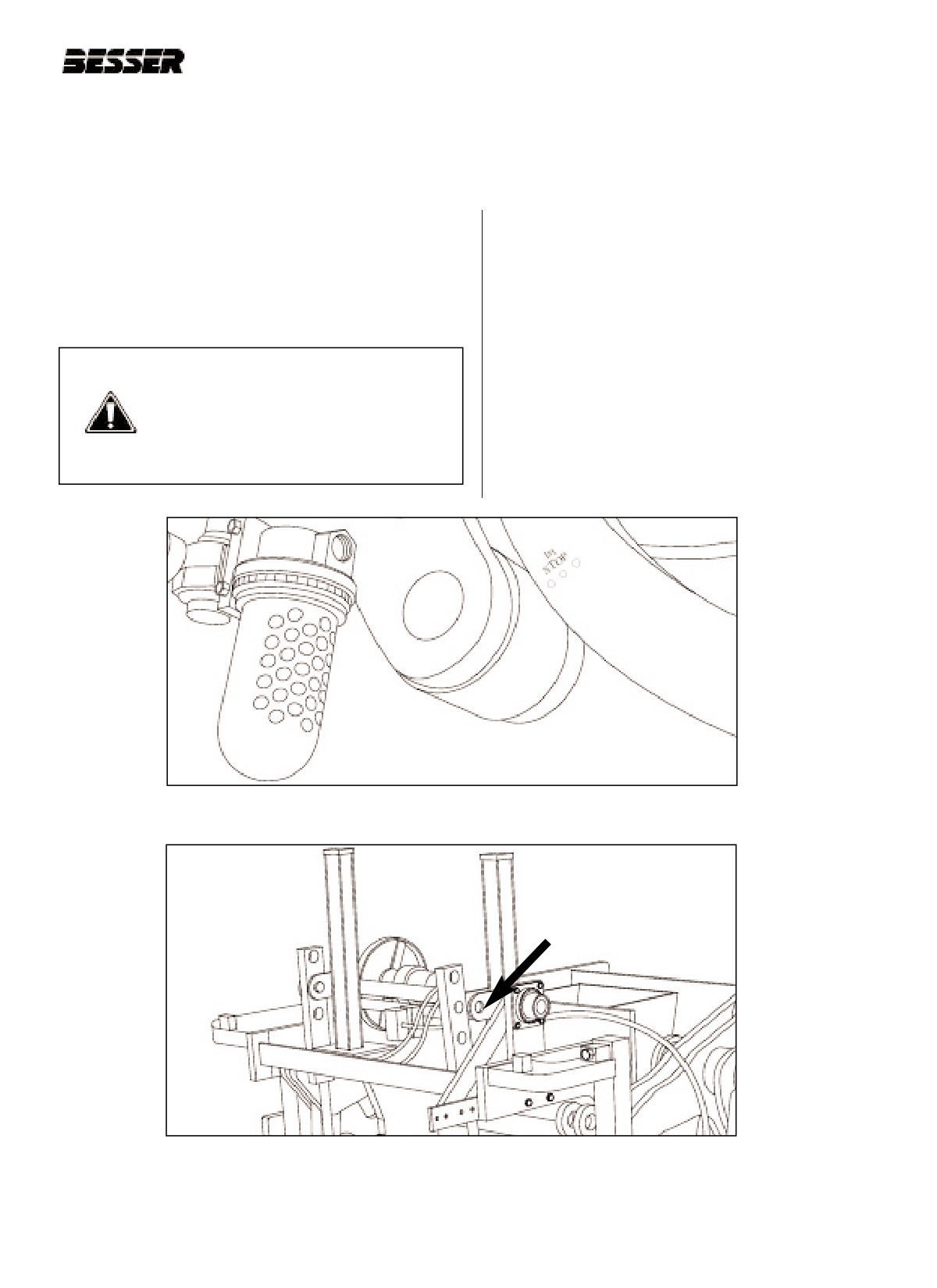
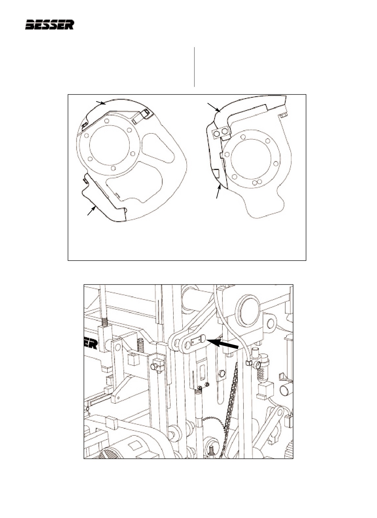
4.3.4 Remove the stripping cam insert from each side
4.3.5 The following items should be positioned as
of the machine. This concrete unit is run without
shown on figures 4.43 and 4.44.
any stripping cam insert (see figure 4.42).
a. Pallet receiver shaft - position pins in inside holes
(short stroke)(see figure 4.43).
RAISING
STRIPPING
INSERT
INSERT
LOWERING
INSERT
LOWERING
INSERT
STRIPPER HEAD RAISING AND
LOWERING CAM
STRIPPING CAM
CENTER CAM RIGHT HAND SIDE
INNER MOST CAM ON BOTH SIDES
Figure 4.42
REMOVING STRIPPING CAM INSERTS.
Figure 4.43
PALLET RECEIVER SHAFT POSITION.
466361F9710US F1 29OC99
4-25
SECTION 4
MACHINE SET UP FOR 80MM HIGH UNITS OPERATION/MAINTENANCE MANUAL
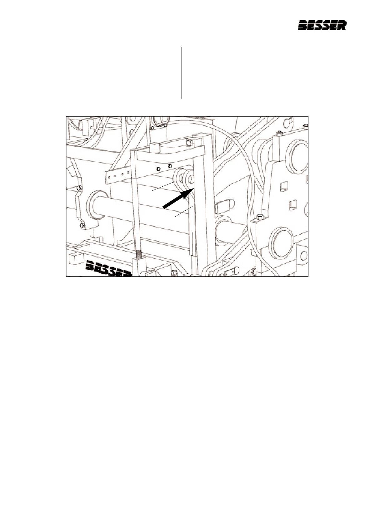
b. Stripper head shaft (A) - position pins in inside
holes (short stroke) (see figure 4.44).
c. Stripper head links (B) - position pins in top holes.
Adjust links to obtain approximately 105mm [4
1/8"] between link ends (see figure 4.44).
A
B
Figure 4.44
STRIPPER HEAD SHAFT AND LINKS.
4-26
466361F9710US F1 29OC99
SECTION 4
MACHINE SET UP FOR 80MM HIGH UNITS
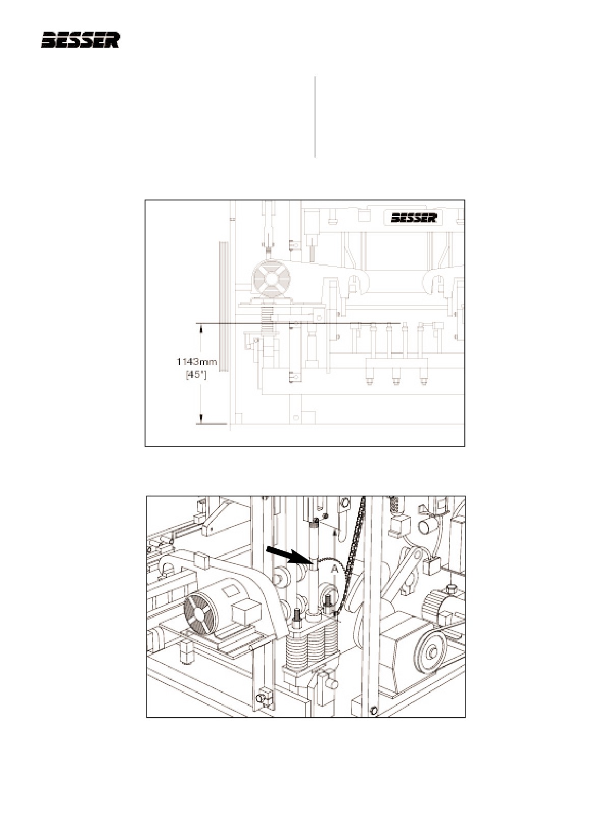
4.3.6 Run machine to "first stop." Turn off clutch and
rod between the upper link end and the boss on
drive motor, and adjust the pallet receiver links to
the spring assembly (see dimension "A" on figure
obtain a dimension of 1143mm [45"] from the top
4.46).
of the base plate to the tops of the pallet receiver
rubbers (see figure 4.45). This adjustment should
expose approximately 600mm [23 5/8"] of link
Figure 4.45
PALLET RECEIVER RUBBERS ABOVE BASE PLATE.
Figure 4.46
LINK ROD.
466361F9710US F1 29OC99
4-27
SECTION 4
MACHINE SET UP FOR 80MM HIGH UNITS OPERATION/MAINTENANCE MANUAL
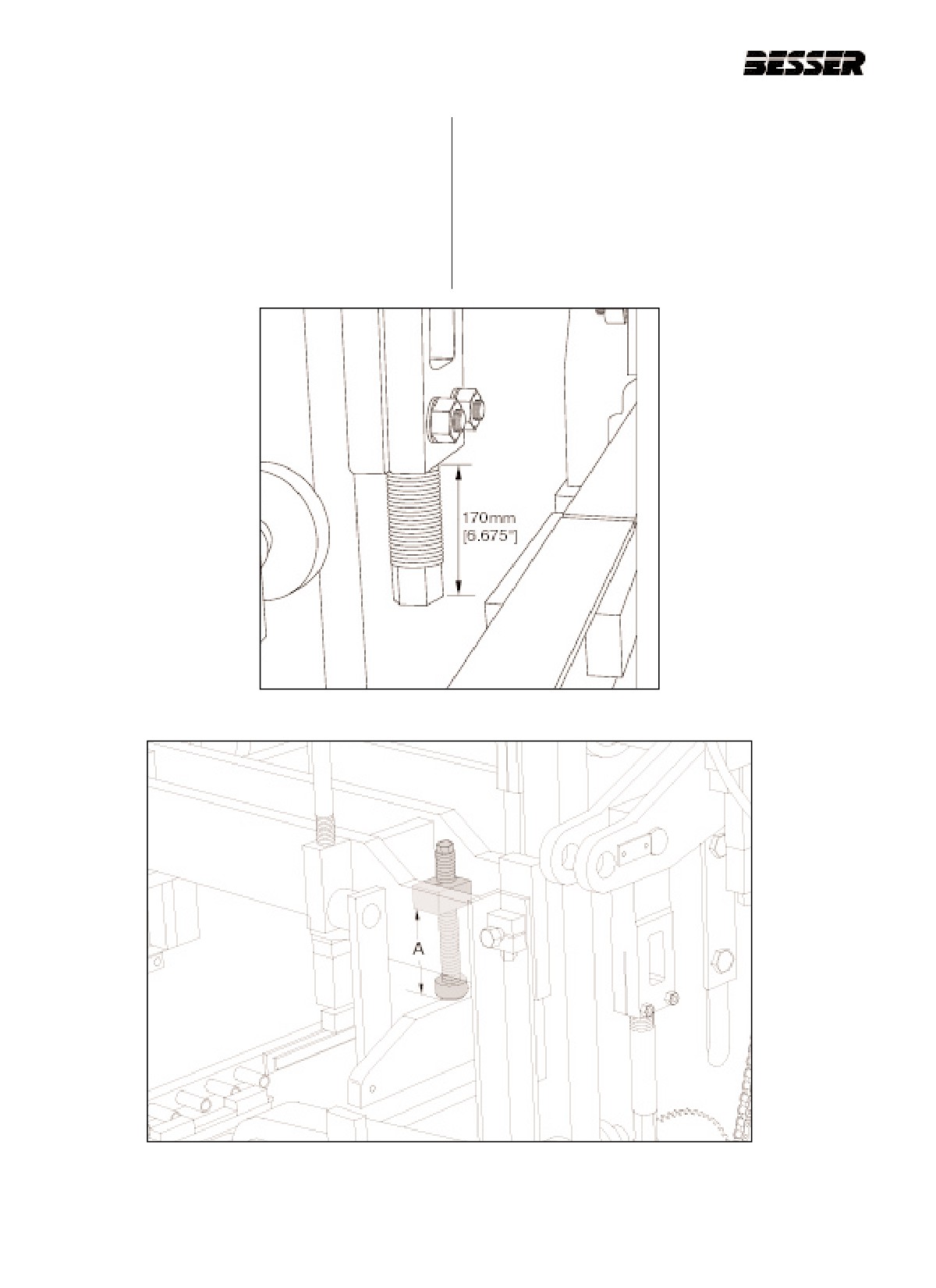
4.3.7 Adjust the upper height stops (part #047356) so
4.3.9 Install sheave (part #112339F2075) on the drive
that 170mm [6.675"] extend past the bottom of
motor.
the castings (figure 4.47).
4.3.8 Install the 445mm (18 1/2") shock absorbers
(part #282177). Adjust the shock absorbers to a
dimension of 300mm [11.812"] (represented by
"A" in figure 4.48) from the bottom of the welded
clamp block to the bottom of the rubber pad.
Figure 4.47
UPPER HEIGHT STOPS.
Figure 4.48
INSTALLING SHOCK ABSORBERS AND ADJUSTING.
4-28
466361F9710US F1 29OC99
SECTION 4
MACHINE SET UP FOR 80MM HIGH UNITS
4.3.10
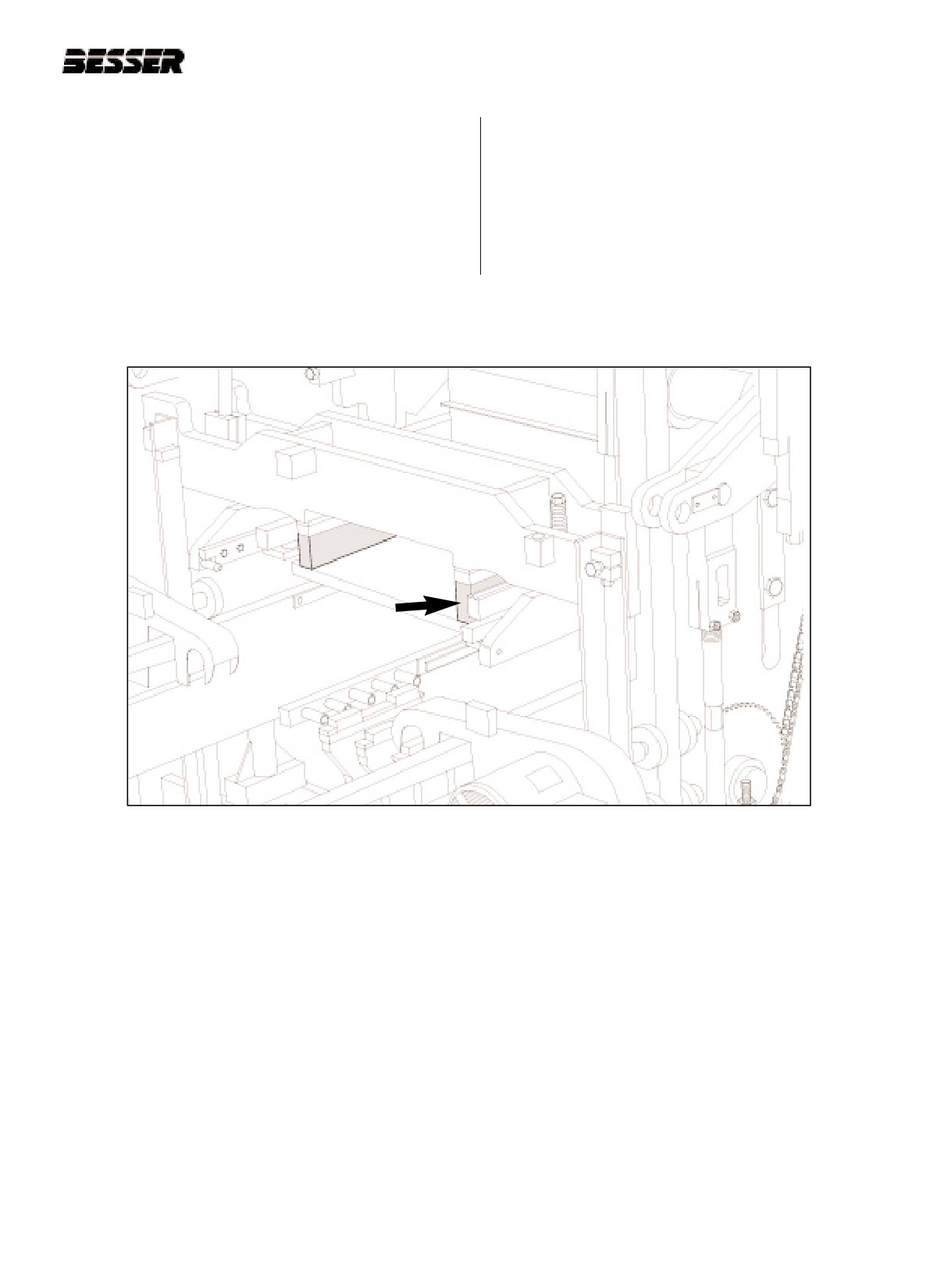
The DYNAPAC is now ready for the installation
of the mold assembly. Follow the directions for
installing an attachment in section 5 of this
manual. When installing the stripper head use
279mm [11"] long bolts (part #087136) and
insert 95mm [3 3/4"] of blocking in addition to
the 38mm [1 1/2"] blocks already affixed to the
stripper head frame (figure 4.49).
Figure 4.49
95mm [3 3/4"] BLOCKING UNDER STRIPPER HEAD FRAME.
466361F9710US F1 29OC99
4-29
SECTION 4
MACHINE SET UP FOR 80MM HIGH UNITS OPERATION/MAINTENANCE MANUAL
4-30
466361F9710US F1 29OC99
SECTION 4
MACHINE SET UP FOR 60MM HIGH UNITS
4.4
60mm HIGH UNITS IN A 67mm HIGH NON-RAMPED MOLD WITH A 360mm HIGH
STRIPPER HEAD ASSEMBLY.
NOTE: THE FOLLOWING INSTRUCTIONS APPLY TO MACHINES WITHOUT QUICK CHANGE CAM INSERTS.
INITIAL CONDITION: No mold in the machine.
Note: Before adjusting or changing any pin positions,
lock-out and tag-out the machine and position
The following instructions will put the machine in
the machine in the stripped through position (pal-
approximate adjustment without the mold in the
let receiver frame resting on blocking and strip-
machine. Final adjustments will be necessary when
per head frame shock absorbers resting on
concrete units are produced. See sections 5 and 6 of
frame.) Then proceed with caution.
this manual.
4.4.1
Run machine to "first stop" (see figure 4.50).
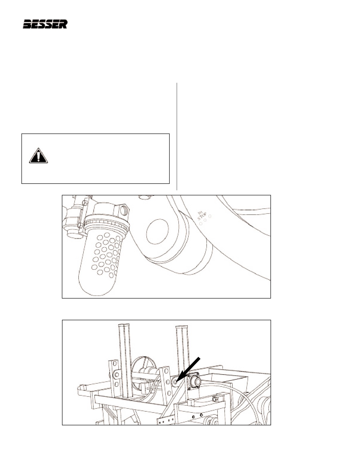
CAUTION: Be sure to mechanically lock
Turn off clutch and drive motor and manually
out the electrical panel when working on
lower the autofeed to its lowest position.
the concrete product machine. Always
Disconnect the autofeed linkage at the top (see
follow the lockout procedure listed in the
figure 4.51).
Safety section of this manual (see sec-
tion 1)!
“First stop” is obtained when the punch marks on the
right side outside cam are in line with the roller.
Figure 4.50
"FIRST STOP" (R.H. side of machine).
Figure 4.51
DISCONNECTING THE AUTOFEED LINKAGES.
(1 of 2 disconnected here)
466361F9710US F1 29OC99
4-31
SECTION 4
MACHINE SET UP FOR 60MM HIGH UNITS OPERATION/MAINTENANCE MANUAL
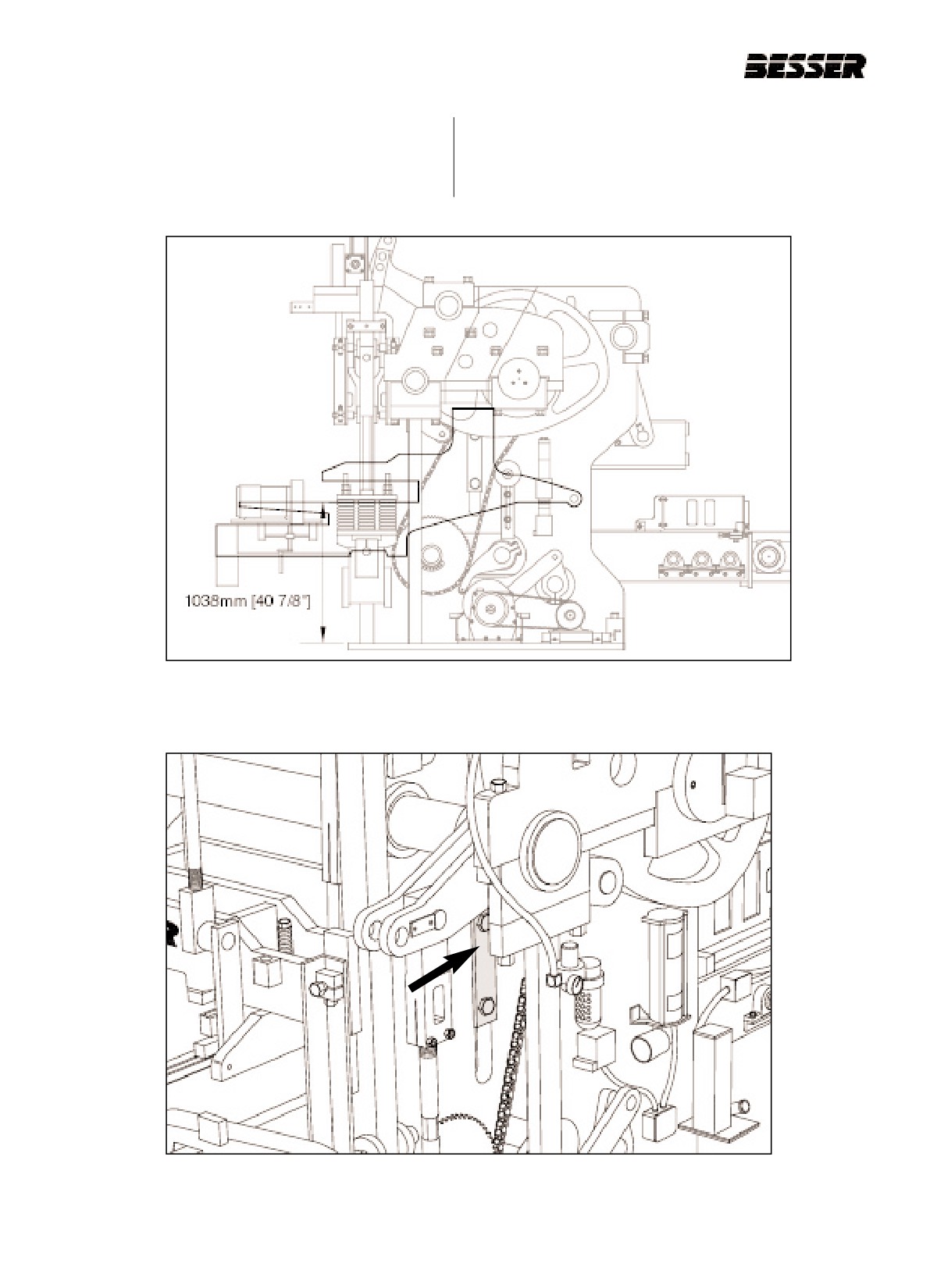
4.4.2 Adjust the inner frame so that the mold throat is
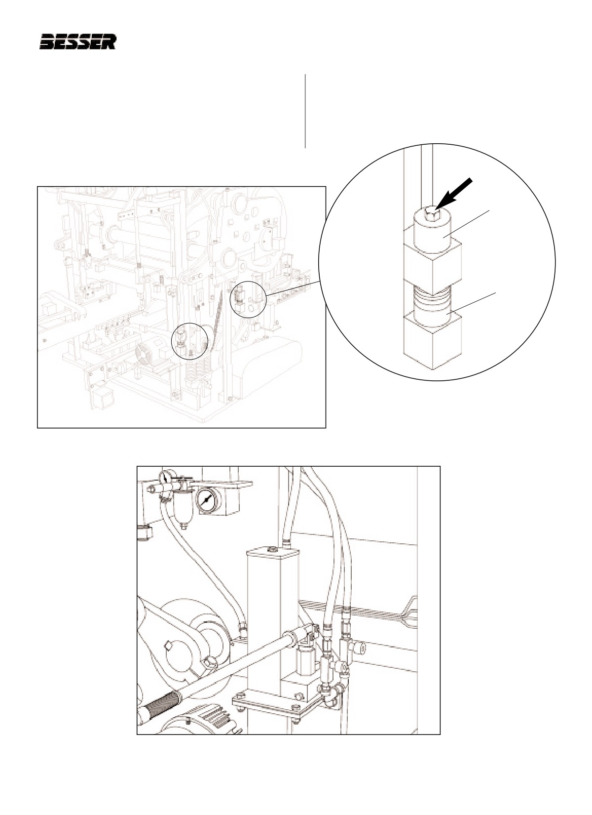
a. Loosen the "T" clamps on each side of machine that
1038mm [40.875”] above the top on the base
secures machine side plate to mold throat plate. (fig-
plate (figure 4.52). 63mm [2 1/4”] of spacers
ure 4.53).
required. To do so, follow this procedure.
Figure 4.52
INNER FRAME ADJUSTMENT.
Figure 4.53
LOOSEN "T" CLAMPS ON BOTH SIDES.
4-32
466361F9710US F1 29OC99
SECTION 4
MACHINE SET UP FOR 60MM HIGH UNITS
b. Loosen bolts at all 4 corners that secure mold throat
d. Allow hydraulic jack system to slowly lower entire
assembly (figure 4.54 and 4.55). Remove top spac-
mold throat assembly until supports are together at
ers.
all 4 corners.
c. Raise mold throat frame up by using hydraulic jacks
system (figure 4.56) just high enough to allow all
lower spacers to be removed or added at all four
corners.
TOP SPACERS
LOWER
SPACERS
(TO BE
REMOVED)
Figure 4.55
LOOSEN BOLTS
Figure 4.54
BOLTS AT ALL 4 CORNERS. (RIGHT SIDE SHOWN)
Figure 4.56
HYDRAULIC JACK SYSTEM.
466361F9710US F1 29OC99
4-33
SECTION 4
MACHINE SET UP FOR 60MM HIGH UNITS OPERATION/MAINTENANCE MANUAL
e. Store spacers on bottom side of bolt for front bolts
and left hand rear bolt. For right hand rear bolt store
spacers on top. Tighten bolts at all 4 corners that
secure mold throat plate spacers (see figure 4.57).
f. Tighten "T" clamps on each side of machine that
secures machine side plate to mold throat plate.
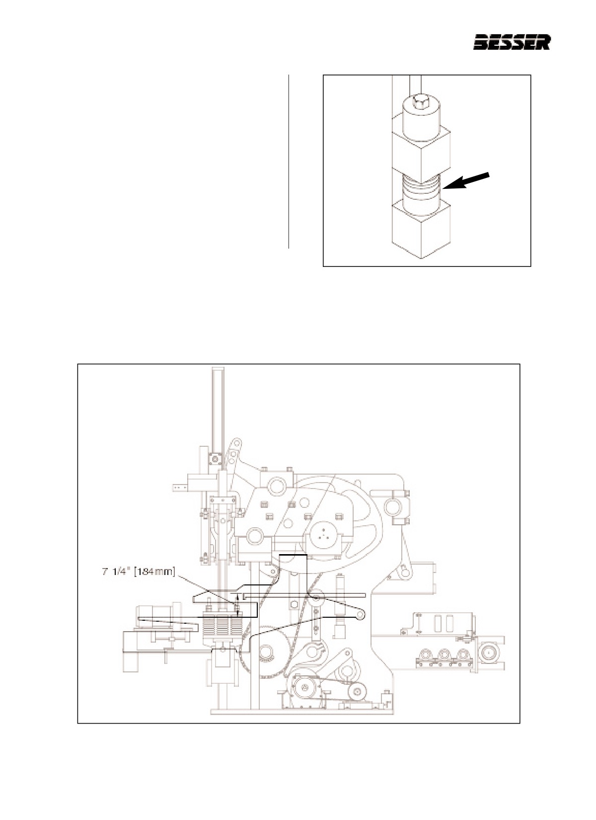
4.4.3 Reconnect autofeed linkage and adjust so that
the top of the apron plate is 184mm [7 1/4”]
above the mold throat at the lowest position of the
autofeed (see figure 4.58). To adjust, lower or
raise the autofeed until apron plate is in correct
position.
Figure 4.57
63mm (2 1/2") OF SPACERS
Figure 4.58
APRON PLATE ABOVE MOLD THROAT ADJUSTMENT.
4-34
466361F9710US F1 29OC99
SECTION 4
MACHINE SET UP FOR 60MM HIGH UNITS
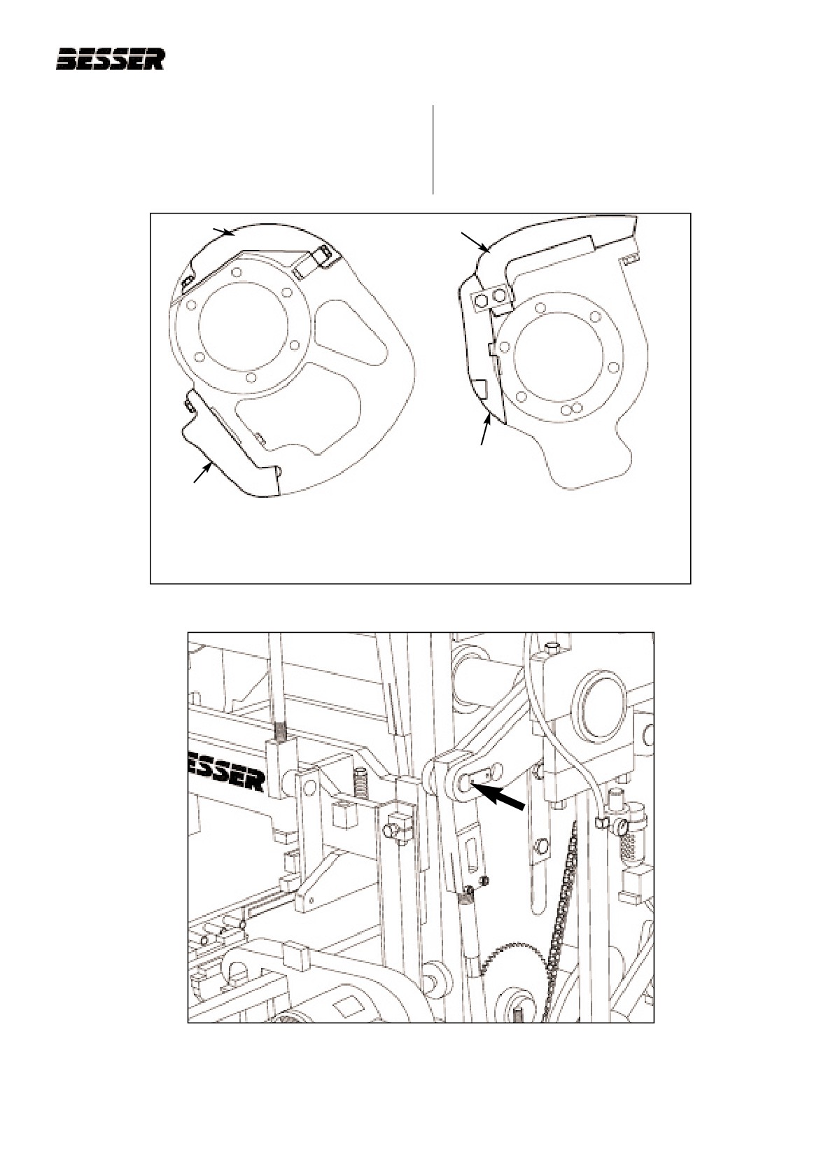
4.4.4 Remove the stripping cam insert from each side
4.4.5 The following items should be positioned as
of the machine. This concrete unit is run without
shown on figures 4.60 and 4.61:
any stripping cam inserts (see figure 4.59).
a. Pallet receiver shaft - position pins in outside
holes (long stroke)(see figure 4.60).
RAISING
STRIPPING
INSERT
INSERT
LOWERING
INSERT
LOWERING
INSERT
STRIPPER HEAD RAISING AND
LOWERING CAM
STRIPPING CAM
CENTER CAM RIGHT HAND SIDE
INNER MOST CAM ON BOTH SIDES
Figure 4.59
STRIPPING CAM INSERTS.
Figure 4.60
PALLET RECEIVER SHAFT POSITION.
466361F9710US F1 29OC99
4-35
SECTION 4
MACHINE SET UP FOR 60MM HIGH UNITS OPERATION/MAINTENANCE MANUAL
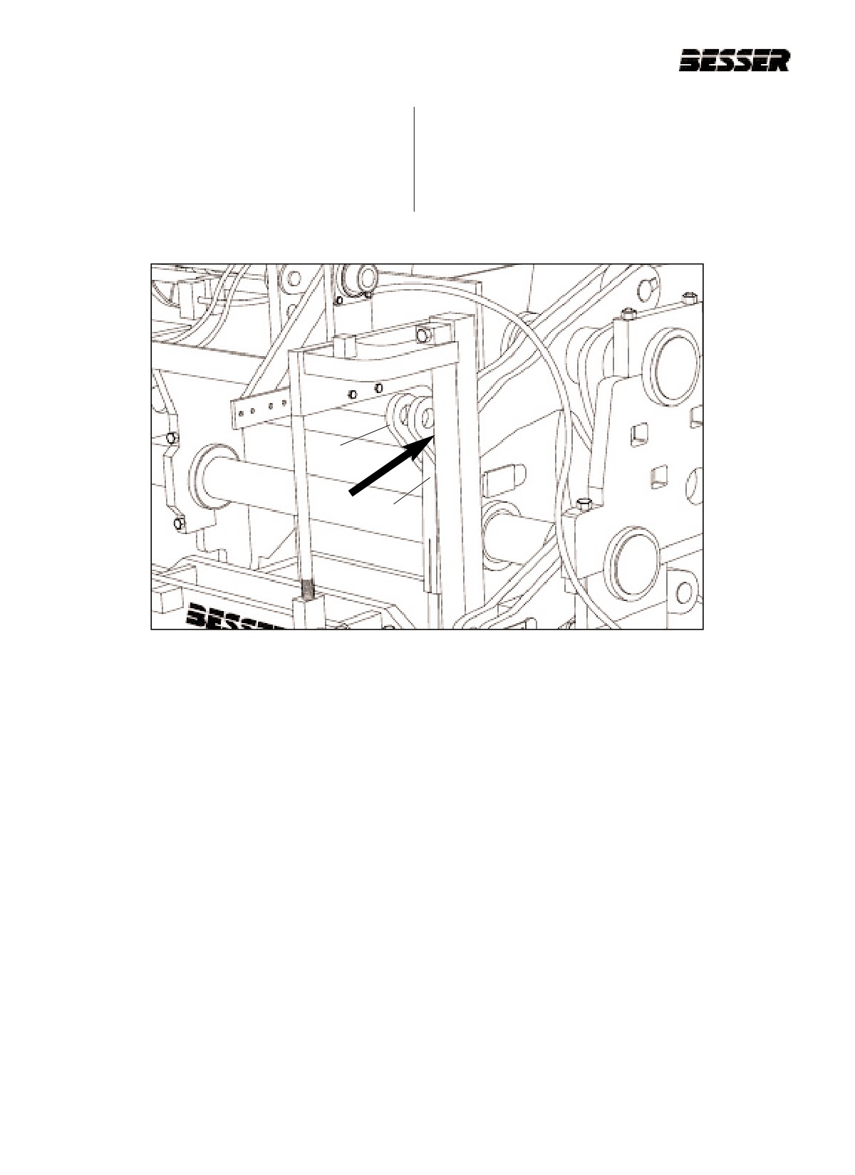
b. Stripper head shaft (A) - position pins in inside
holes (short stroke) (see figure 4.61).
c. Stripper head links (B) - position pins in top holes.
Adjust links to obtain approximately 105mm (4
1/8") between link ends (see figure 4.61).
A
B
Figure 4.61
STRIPPER HEAD SHAFT AND LINKS.
4-36
466361F9710US F1 29OC99
SECTION 4
MACHINE SET UP FOR 60MM HIGH UNITS
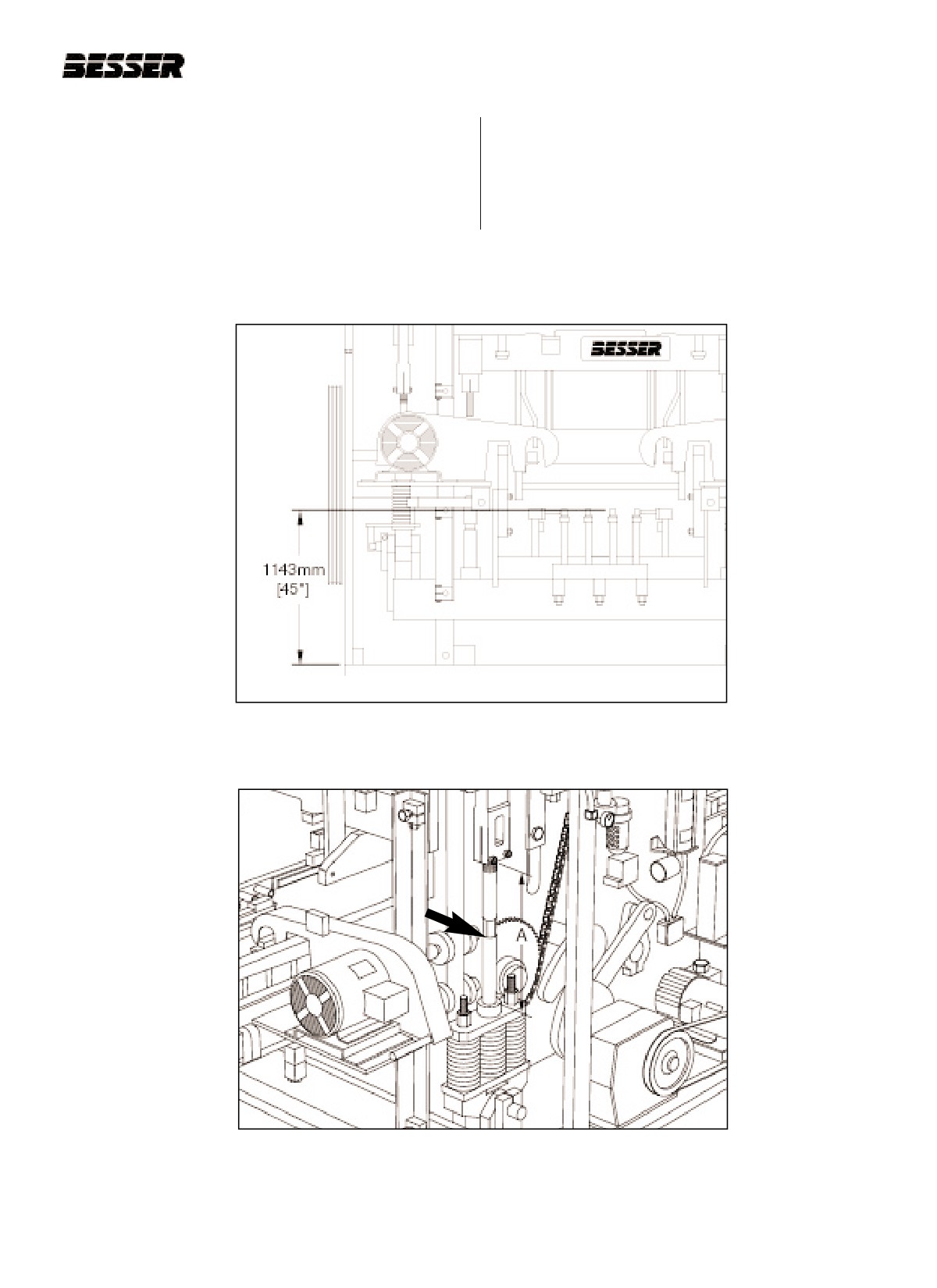
4.4.6 Run machine to "first stop." Turn off clutch and
rod between the upper link end and the boss on
drive motor, and adjust the pallet receiver links to
the spring assembly (see dimension "A" on figure
obtain a dimension of 1143mm [45"] from the top
4.63).
of the base plate to the tops of the pallet receiver
rubbers (see figure 4.62). This adjustment should
expose approximately 600mm [23 5/8"] of link
Figure 4.62
PALLET RECEIVER RUBBERS ABOVE BASE PLATE.
Figure 4.63
LINK ROD.
466361F9710US F1 29OC99
4-37
SECTION 4
MACHINE SET UP FOR 60MM HIGH UNITS OPERATION/MAINTENANCE MANUAL
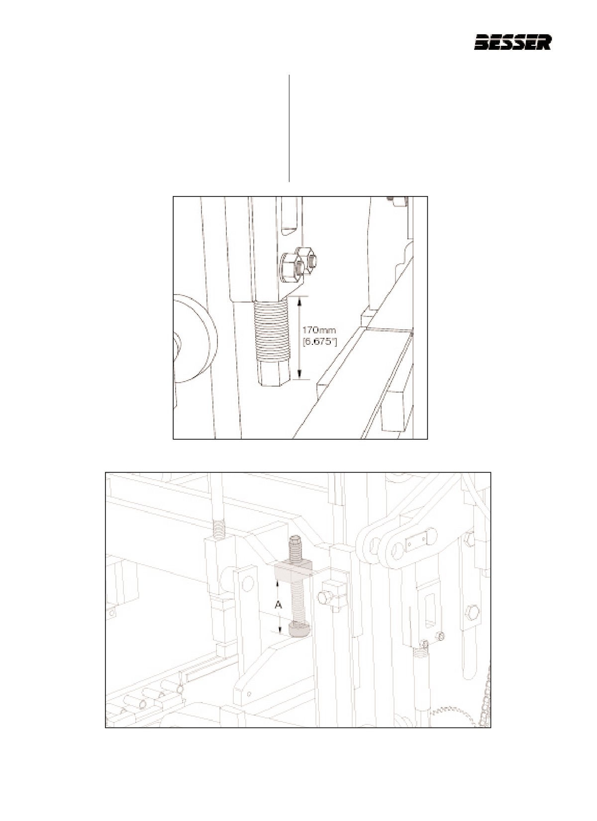
4.4.7 Adjust the upper height stops (part #047356) so
4.4.9 Install sheave (part #112339F2075) on the drive
that 170mm [6.675"] extend past the bottom of
motor.
the castings (figure 4.64).
4.4.8 Install the 470mm [18 1/2"] shock absorbers
(part #282177). Adjust the shock absorbers to a
dimension of 300mm [11.812"] (represented by
"A" in figure 4.65) from the bottom of the welded
clamp block to the bottom of the rubber pad.
Figure 4.64
UPPER HEIGHT STOPS.
Figure 4.65
INSTALLING SHOCK ABSORBERS AND ADJUSTING.
4-38
466361F9710US F1 29OC99
SECTION 4
MACHINE SET UP FOR 60MM HIGH UNITS
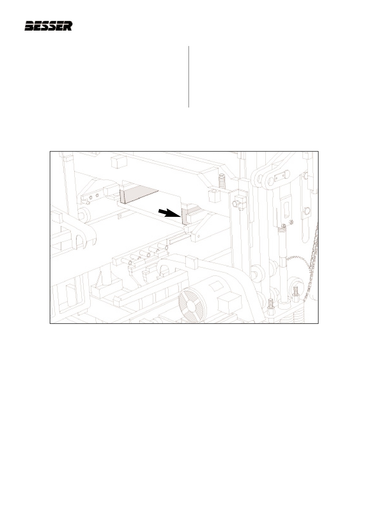
4.4.10 The DYNAPAC is now ready for the installation
of the mold assembly. Follow the directions for
installing an attachment in section 5 of this man-
ual. When installing the stripper head use 279
mm (11") long bolts (part #087136) and insert
95mm [3 3/4"] of blocking in addition to the
38mm [1 1/2"] blocks already affixed to the strip-
per head frame (figure 4.66).
Figure 4.66
95mm (3 3/4") BLOCKING UNDER STRIPPER HEAD FRAME.
466361F9710US F1 29OC99
4-39
SECTION 4
MACHINE SET UP FOR 60MM HIGH UNITS OPERATION/MAINTENANCE MANUAL
4-40
466361F9710US F1 29OC99
SECTION 5
MOLD INSTALLATION
SECTION 5
MOLD & STRIPPER HEAD INSTALLATION
NOTE: AS AN INITIAL CONDITION, IT IS ESSENTIAL YOU REVIEW SECTION 4 “MACHINE SET UP FOR
SPECIFIC MOLD” BEFORE GOING THROUGH THIS SECTION.
5.1
BESSER MOLD ASSEMBLY &
5.1.7
Stripper shoes should be torqued to 65 - 75 LB-
FT, (100 - 110 N-M).
TORQUE REQUIREMENTS.
5.1.8
Align the stripper shoes.
Longer mold life can be achieved by observing a few
5.1.9
Secure plungers to stripper head plate - 100 -
basic rules. Be sure to clean all parts and mating sur-
140 LB-FT, (150 - 210 N-M).
faces thoroughly before assembly. Always be sure
parts are properly aligned and use proper torque
5.1.10 Center vibrator weights as close as possible to
requirements. To assure that parts are square, start
assure uniform vibration and that the nuts face
with a good working surface (mold jig). A visual inspec-
towards the outside of the mold. Double weights
tion is suggested to make sure parts are not burred or
should be located 0.5" [12.5mm] from edge of
scored.
bearing enclosure.
Note: Always start with new lock washers and use
Note: If the machine is equipped with optional
only a brass hammer.
Smartpac vibration system, vibrator weights are
factory-positioned on shaft.
Note:
Use an adequate torque wrench to tighten at the
proper torque.
5.2
JOGGING AND RUNNING THE
5.1.1
Outside division plates should be torqued to 625
- 675 LB-FT, (930 - 1005 N-M). Outside division
MACHINE.
plates with cutouts for face liners should be
torqued to 175 - 195 LB-FT (260 - 290 N-M).
There is two ways to operate the machine: you can jog
it, or simply run it. Run the machine when you want to
5.1.2
Threaded inside division plates should be
cycle it. Jog the machine when you want to stop the
torqued to 40 - 50 LB-FT, (60 - 70 N-M). Tanged
machine at a precise position. All controls to jog or run
inside division plates should be torqued to 100 -
the machine are located on the Graphic Control Station
120 LB-FT, (150 - 180 N-M).
(please refer to section 9 for more details).
5.1.3
End liners should be torqued to 100 - 140 LB-FT,
1. To run the machine, follow this procedure:
(150 - 210 N-M).
A) Push the "MAIN DRIVE START" button.
5.1.4
Core bars should first be fitted initially front and
back.
B) With the main drive running, turn the
"CLUTCH" selector switch to "ON". The
5.1.5
Core bars should be torqued to 70 - 90 LB-FT,
machine starts cycling.
(105 - 135 N-M). Align front and back as uniform-
ly as possible to the mold side bars. Check cores
2. To jog the machine, follow this procedure:
for center between division plates to assure uni-
formly block dimensions. (A wire can be secured
A) Turn the "CLUTCH" selector switch to "JOG".
through the hold down bolt heads as a safety to
prevent the bolts from coming loose during con-
B) Depress and release the "JOG" button to move
stant vibration.)
the machine gradually as the main drive is
functioning.
5.1.6
Vibrator bolts should be torqued to 220 - 300 LB-
FT, (330 - 450 N-M).
466361F9710US F1 29OC99
5-1
SECTION 5
MOLD INSTALLATION
5.3
REMOVING A MOLD
Follow this step by step procedure in order to remove a
mold and stripper head from a DYNAPAC.
5.3.1
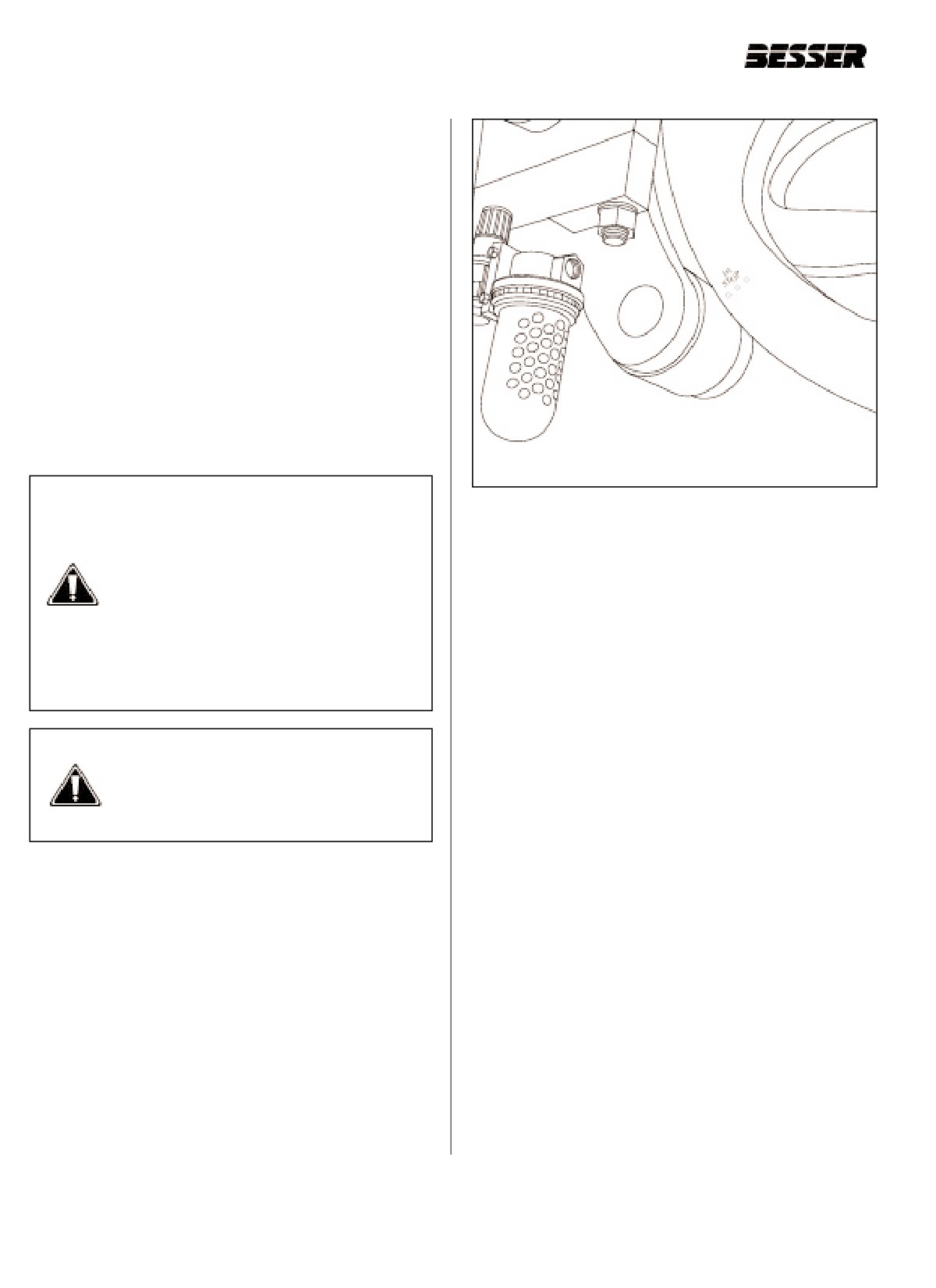
Run machine to “first stop” (feed box all the way
forward). See figure 5.1.
5.3.2
Shut off clutch and turn power off. Wait until
motor has stopped completely.Also, lock out
machine.
5.3.3
Remove cut off bar and agitator grid.
5.3.4
Make sure no one is standing on or near
machine and turn power back on. Hit MCR reset
button and start drive motor.
DANGER: Always turn power off and
Figure 5.1
“FIRST STOP” (R.H. side of machine).
mechanically lock out electrical panel
before working on Concrete Product
Machine. Always follow the safety tips
listed in the Safety section of this manual
5.3.8
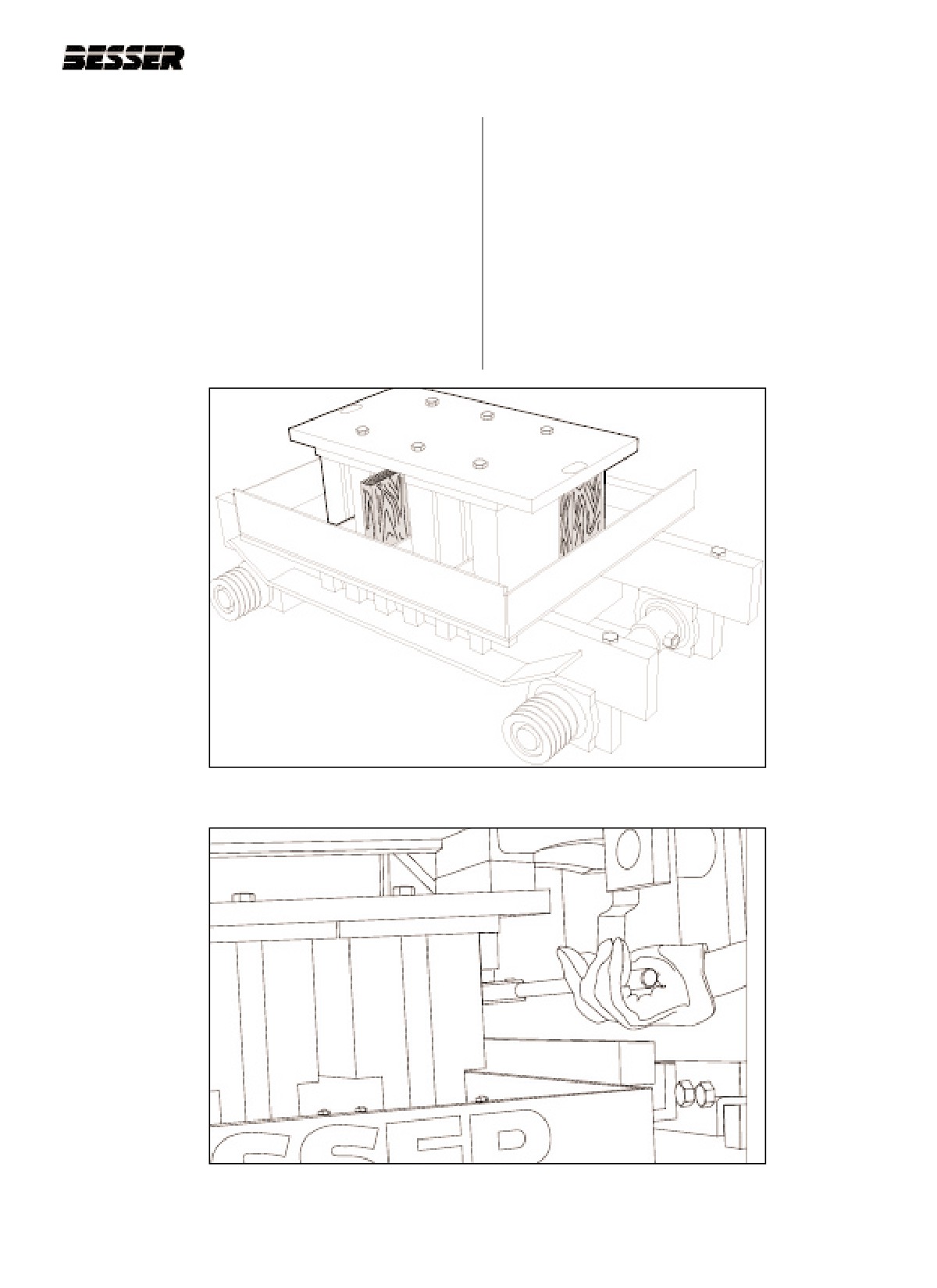
Put 2 X 4’s wooden blockings in mold as shown
(see section 1). During the course of the
in figure 5.2.Use two pieces of 2" x 4" x 8" wood
following procedure, you will be asked to
blocking, and one piece of 2” x 4" x 7-1/2” to
periodically turn power off and lock out
assure a space between stripper head plate and
machine. It is important you do so for
mold top plate. Use the 8" blockings in the rear
your safety and the safety of personnel
corners and the 7-1/2” blocking in the front cen-
working on the DYNAPAC !
ter to clear bolt holes in the stripper head top
plate
WARNING: No one should be standing
next to machine when running machine
to “first stop”. Feed box coming forward
is dangerous and could lead to serious
injuries!
5.3.5
Run machine to “third stop”. (Stripper head
frame and pallet receiver frame all the way
down.
5.3.6
Turn clutch to "JOG" until stripper head is high
enough above mold to insert blockings inside
mold.
5.3.7
Shut off clutch and turn power off. Wait until
motor has stopped completely.Also, lock out
machine.
5-2
466361F9710US F1 29OC99
SECTION 5
MOLD INSTALLATION
5.3.9
Make sure no one is standing on or near
5.3.12 Remove bolts holding the head assembly (figure
machine and turn power back on. Hit MCR reset
5.3).
button. Do not start main drive motor.
5.3.13 Make sure no one is standing on or near
5.3.10 Jog machine until stripper head frame is resting
machine and turn power back on. Hit MCR reset
on 2 X 4’s blockings. Weight of stripper head
button.
will turn machine in reverse.
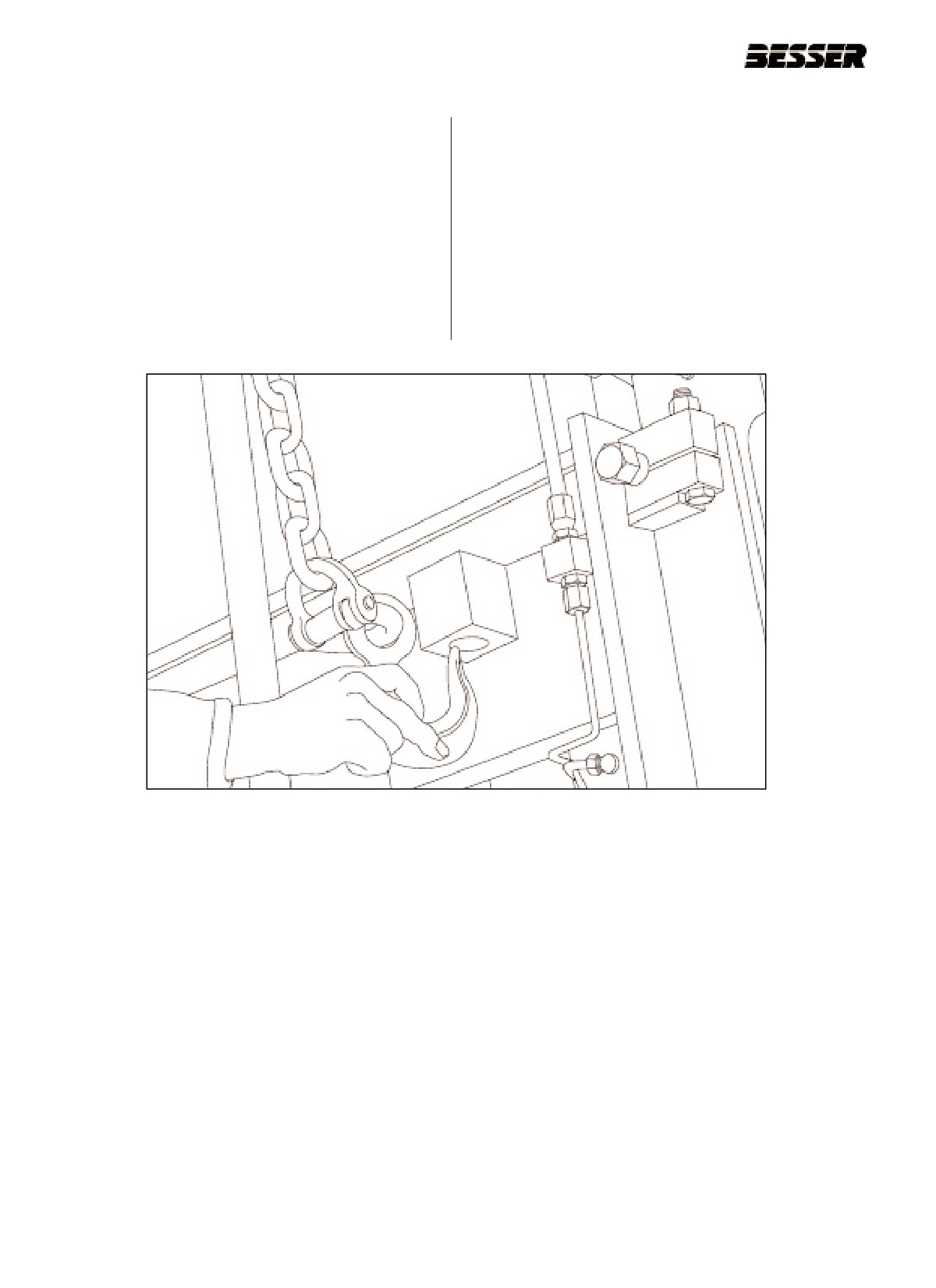
5.3.14 Jog machine to bring stripper head high enough
5.3.11 Shut off clutch and turn power off. Wait until
to connect safety chain (figure 5.4).
motor has stopped completely. Also, lock out
machine.
5.3.15 Shut off clutch and turn power off. Wait until
motor has stopped completely. Also, lock out
machine.
Figure 5.2
WOODEN BLOCKINGS IN MOLD.
Figure 5.3
REMOVING BOLTS FROM BOLT STRIPPER HEAD PLATE.
466361F9710US F1 29OC99
5-3
SECTION 5
MOLD INSTALLATION
5.3.16 Hook safety chain as shown in figure 5.4.
5.3.20 Shut off clutch and turn power off. Wait until
motor has stopped completely. Also, lock out
5.3.17 Make sure no one is standing on or near
machine.
machine and turn power back on. Hit MCR reset
button. Do not start main drive motor.
5.3.18 Jog clutch until stripper head comes down and
is supported by safety chain.
5.3.19 Keep jogging until pallet receiver is at lowest
position.
Figure 5.4
ATTACHING STRIPPER HEAD FRAME WITH SAFETY CHAIN.
5-4
466361F9710US F1 29OC99
SECTION 5
MOLD INSTALLATION
5.3.21 Disconnect vibrator shaft hose from dump valve
5.3.24 Remove V-belts from vibrating motor sheaves to
and cap (on Smartpac vibration system only).
vibrating shaft sheaves.
5.3.22 Lift up vibrator guards.
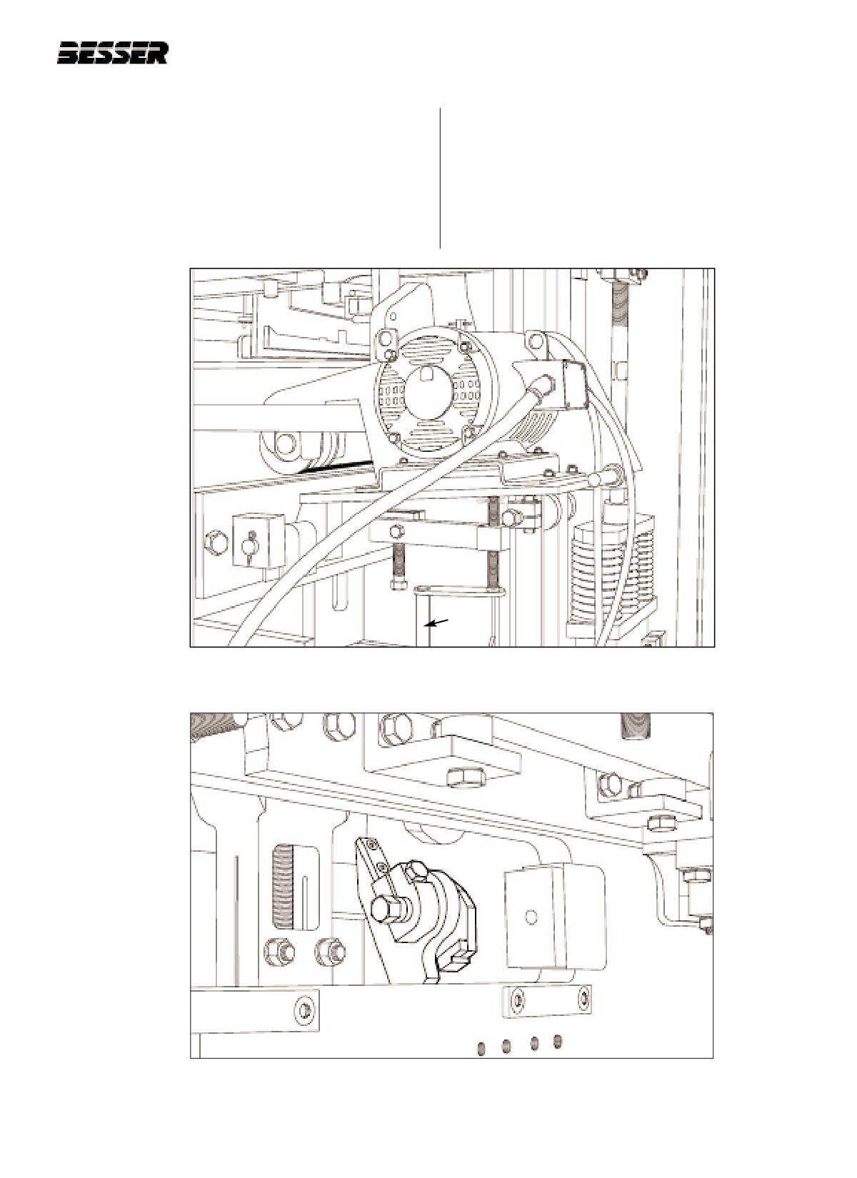
5.3.25 Open mold locks (left and right) as shown in fig-
ure 5.6.
5.3.23 Raise both vibrator motors with screw jacks (C)
(see figure 5.5).
C
Figure 5.5
RAISING THE VIBRATOR MOTORS WITH SCREW JACK (C).
Figure 5.6
MOLD LOCKS IN OPEN POSITION (LEFT LOCK SHOWN).
466361F9710US F1 29OC99
5-5
SECTION 5
MOLD INSTALLATION
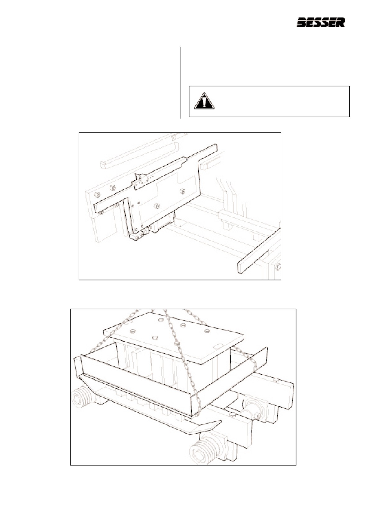
5.3.26 If your machine is equipped with a Mold
5.3.28 Chain mold as shown in figure 5.8.
Insertion Device, push carriages under shaft
assembly of mold. Then raise carriage to carry
5.3.29 Remove mold. We recommend the use of an
position using the hand control. Figure 5.7
overhead crane.
shows the Mold Insertion Device in its lower
position.
CAUTION: Molds are heavy pieces of
5.3.27 Pull mold forward.
equipment. Handle with extreme care.
Figure 5.7
MOLD INSERTION DEVICE IN LOWER POSITION.
This figure has been simplified for illustration purposes.
Figure 5.8
MOLD IS CHAINED, READY TO BE TAKEN OUT OF MACHINE.
5-6
466361F9710US F1 29OC99
SECTION 5
MOLD INSTALLATION
5.4
INSTALLING THE MOLD.
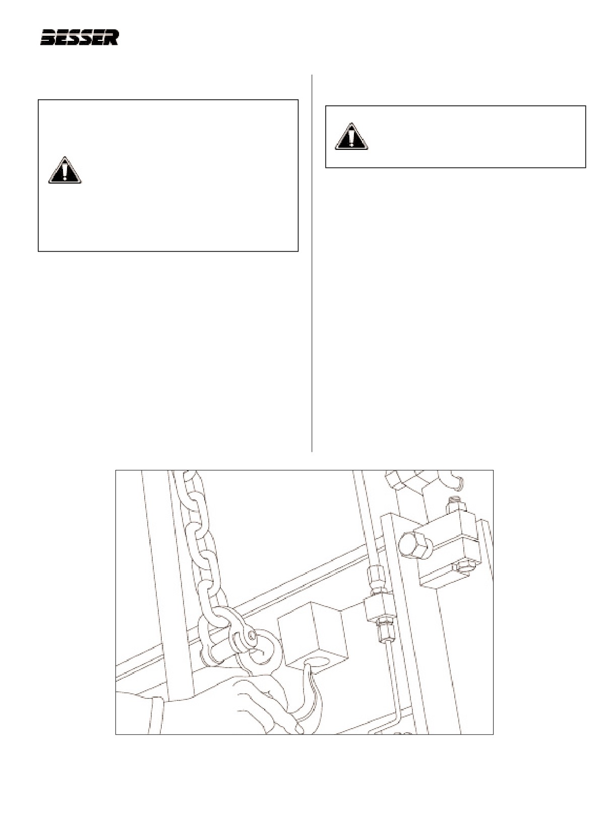
5.4.4
Hook safety chain to stripper head frame (see
figure 5.9).
DANGER: Always turn power off and
mechanically lock out electrical panel
DANGER: Do not go on with this proce-
before working on Concrete Product
dure without hooking safety chain to
Machine. Always follow the safety tips
stripper head frame!
listed in the Safety section of this manual
(see section 1). During the course of the
following procedure, you will be asked to
5.4.5
Make sure no one is standing on or near
periodically turn power off and lock out
machine and turn power back on. Hit MCR reset
machine. It is important you do so for
button. Do not start main drive motor
your safety and the safety of personnel
working on the DYNAPAC !
5.4.6
Jog the machine to lower the stripper head so it
hooks on the safety chain. The pallet receiver
will lower. When it is low enough to allow easy
A. Preparing the machine for the mold
mold change without interference with pallet
receiver, that is sufficient.
5.4.1
Starting with machine in a stripped through posi-
tion, both the pallet receiver frame and the strip-
5.4.7
Shut off clutch and turn power off. Wait until
per head frame are all the way down. Mold locks
motor has stopped completely. Also, lock out
are in closed position and latched.
machine.
5.4.2
Jog the machine until the stripper head is high
Note: Sometimes the main drive pulley (ref. page 2.5)
enough to hook up safety chain but before the
may have to be manually rotated clockwise to
feedbox starts forward (figure 5.9).
allow the pallet receiver to lower. To do so, the
motor should be stopped and the clutch on.
5.4.3
Shut off clutch and turn power off. Wait until
motor has stopped completely. Also, lock out
machine.
Figure 5.9
ATTACHING STRIPPER HEAD FRAME WITH SAFETY CHAIN.
466361F9710US F1 29OC99
5-7
SECTION 5
MOLD INSTALLATION
5.4.8
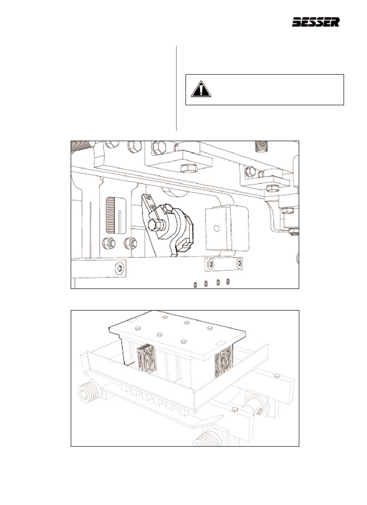
Open mold locks as shown in figure 5.10 below
Note:Make sure the cutoff bar and the agitator grid
(one on each side).
have been removed before putting a mold in the
machine !
5.4.9
Place stripper head down in mold using two
pieces of 2" x 4" x 8" wood blocking, and one
CAUTION: Stripper heads are heavy
piece of 2” x 4" x 7-1/2” to assure a space
pieces of equipment. Handle with
between stripper head plate and mold top plate.
extreme care.
Use the 8" blockings in the rear corners and the
7-1/2” blocking in the front center to clear bolt
holes in the stripper head top plate (see figure
5.11).
Figure 5.10
MOLD LOCKS IN OPEN POSITION (LEFT LOCK SHOWN).
Figure 5.11
STRIPPER HEAD POSITIONED IN MOLD.
5-8
466361F9710US F1 29OC99
SECTION 5
MOLD INSTALLATION
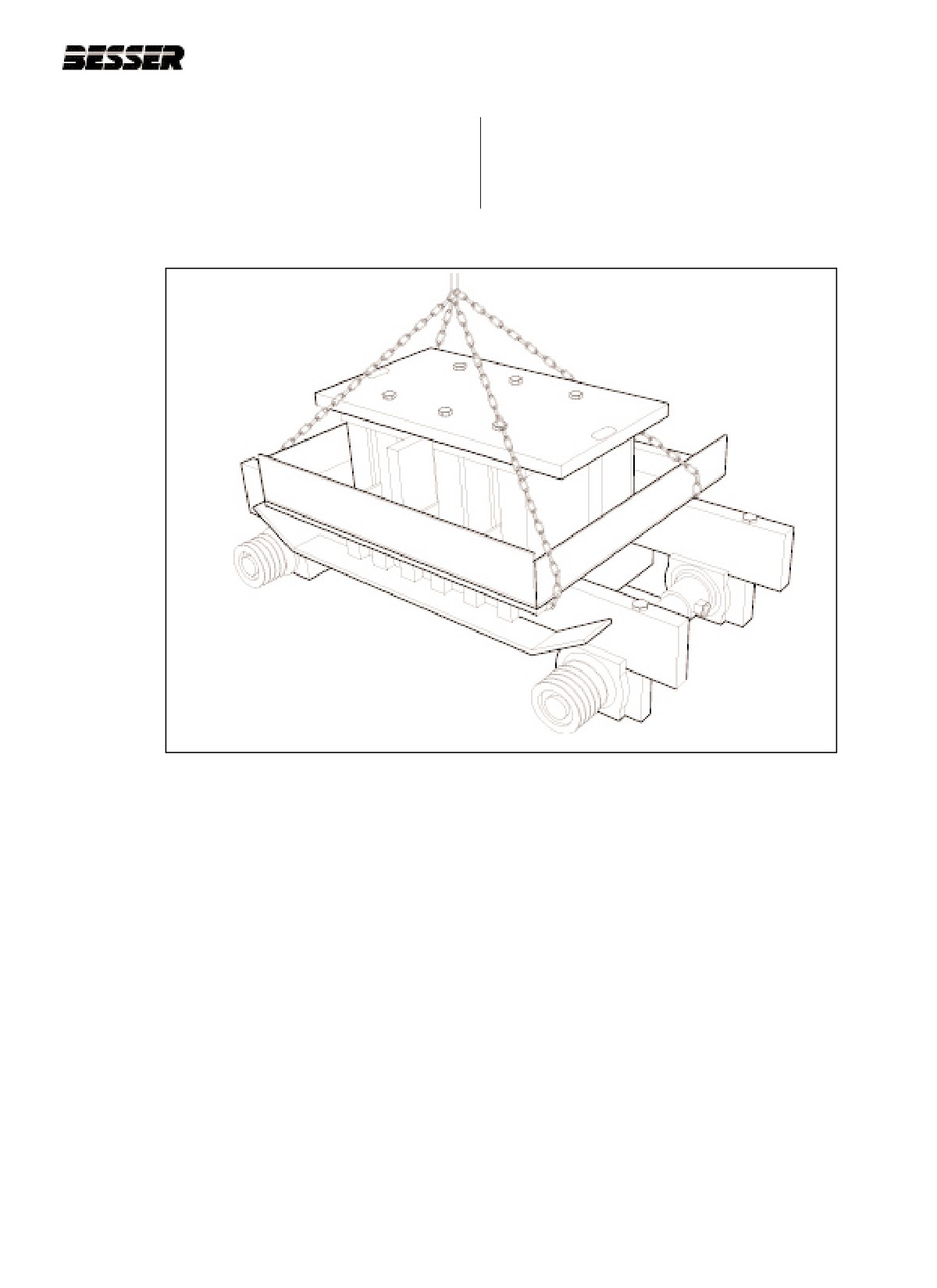
5.4.10 Chain mold with stripper head as shown in fig-
ure 5.12 below. We recommend the use of an
overhead crane. The weight of a complete mold
is approximately between 2000 lbs [910 Kg] and
2500 lbs [1135 Kg].
Mold is now ready to be placed in machine.
Figure 5.12
MOLD IS CHAINED, READY TO BE PLACED IN MACHINE.
466361F9710US F1 29OC99
5-9