DYNAPAC Vibratory roller CC224HF/324HF/384HF, CC2200/3200/3800, CC3800H. Instruction manual (2023) - page 4
Maintenance - Maintenance schedule
Every 2000 hours of operation
Refer to the contents to find the page number of the
sections referred to !
Pos.
Action
Comment
in fig
3
Change the diesel engine oil and oil filter **,***
Refer to the engine manual
**) Deutz, 500h or once every
6 months
***) Cummins, 1000h or once
a year
3
Replace fuel filter
3
Replace fuel filter (filter insert*)
*) Deutz
3
Replace engine V-belt *
*) only for Deutz
Check engine valve clearances
Refer to the engine manual
Check the engine belt drive system
Refer to the engine manual
8
Clean the hydraulic fluid cooler/water cooler
Or when necessary
10
Check the filter element in the air cleaner
Replace when necessary
20
Check the condition of the batteries
4
Change the hydraulic fluid filter
7
Check the hydraulic reservoir cover/breather
6
Change the hydraulic fluid
16
Change the oil in the drums
15
Change the oil in the drum gear boxes
19
Check the rubber elements and bolted joints
18
Grease the chair bearing
17
Steering hitch - Tightening
22
Replace the air cleaner filter in the cab
23
Overhaul the air conditioning
21
Lubricate the pivot bearing
Offset drum
9
Change the coolant (glycol)
Every other year
109
Maintenance - Maintenance schedule
110
Maintenance, 10h
Maintenance, 10h
Every 10 hours of operation (Daily)
Park the roller on a level surface.
The engine must be switched off and the
parking brake activated when checking or
adjusting the roller, unless otherwise specified.
Ensure that there is good ventilation (air
extraction) if the engine is run indoors.
Risk of carbon monoxide poisoning.
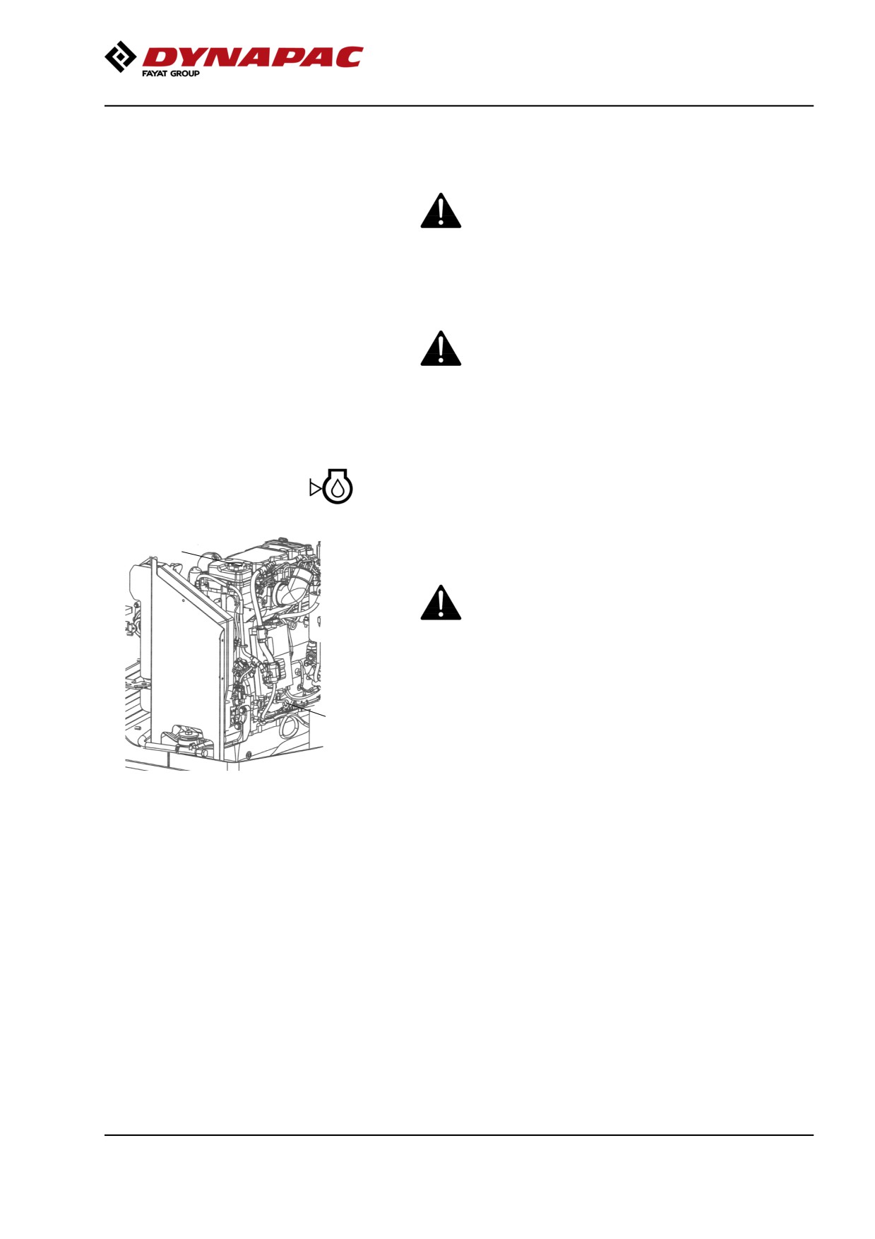
Diesel engine - Check oil level
2
The dipstick is accessed through the right door of the
engine compartment.
Take care not to touch any hot parts of the engine
or the radiator when removing the dipstick. Risk of
burns.
The dipstick is located down on the front of the engine.
1
Pull out the dipstick (1) and check that the oil level is
between the upper and lower marks.
For further details, refer to the engine's instruction
Fig. Engine compartment
manual.
1. Dipstick
2. Oil filler cap
111
Maintenance, 10h
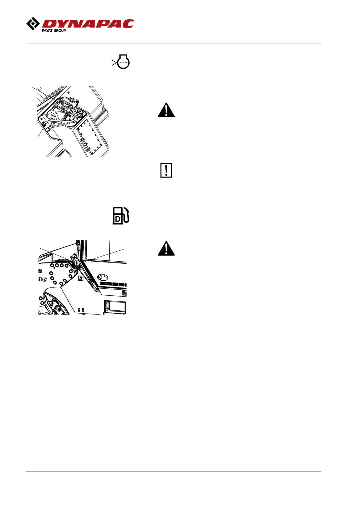
Coolant level - Check
1
Check that the coolant level is between the max. and
min. marks (2).
Observe great caution if the cap has to be opened
while the engine is hot. Wear protective gloves and
goggles.
2
Fill with a mixture of 50% water and 50% anti freeze.
See the lubrication specification in these instructions
and the engine manual.
Fig. Expansion tank
Flush the system every other year and change
1. Filler cap
the coolant. Also check that the air has
2. Level marks
unobstructed passage through the reservoir.
Fuel tank - Refueling
Never refuel while the engine is running. Do not
2
1
smoke and avoid spilling fuel.
The filler pipe and tank cap are on the left side of the
front frame.
Refuel the tank every day before starting work, or fill
Fig. Fuel tank
the tank at end of work. Unscrew the lockable tank cap
1. Tank cap
(1) and fill fuel up to the lower edge of the filler pipe.
2. Filler pipe
The tank holds 130 liters (34 gal) of fuel. Refer to the
engine manual for information on diesel grade.
112
Maintenance, 10h
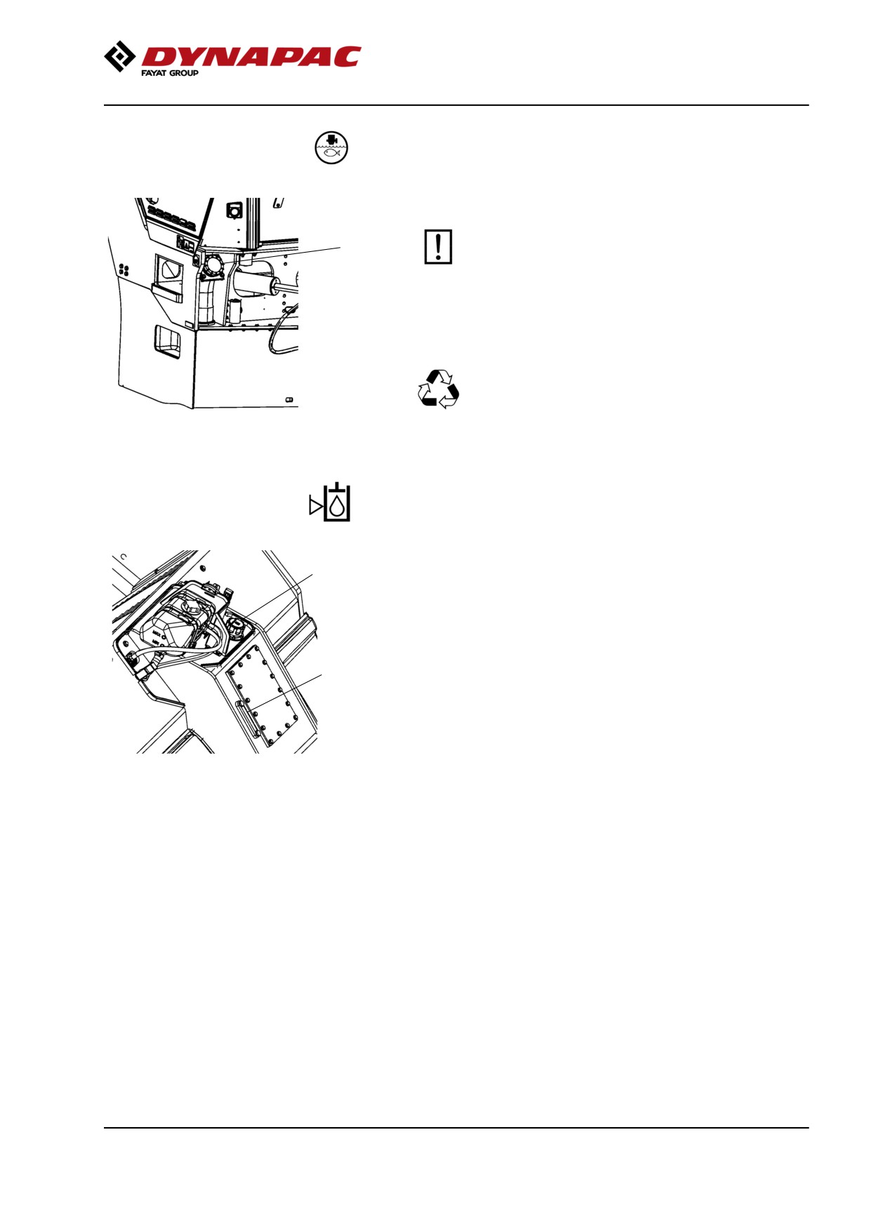
Water tank, Std - Filling
The filler cap is on the rear left side of the front frame.
Unscrew the tank cap (1) and fill with clean
1
water. Do not remove the strainer (2).
Fill the central (standard) tank, it holds 750 liters (198
gal).
Only additive: A small amount of
environment-friendly antifreeze.
Figure. Standard water tank
1. Tank cap
Hydraulic reservoir - Check fluid level
2
Place the roller on a level surface and check that the
oil level in the sight glass (1) is between the max and
min markings. Top up with the type of hydraulic fluid
specified in the lubricant specification, if the level is too
low.
1
Figure. Hydraulic reservoir
1. Oil sight glass
2. Filler cap
113
Maintenance, 10h
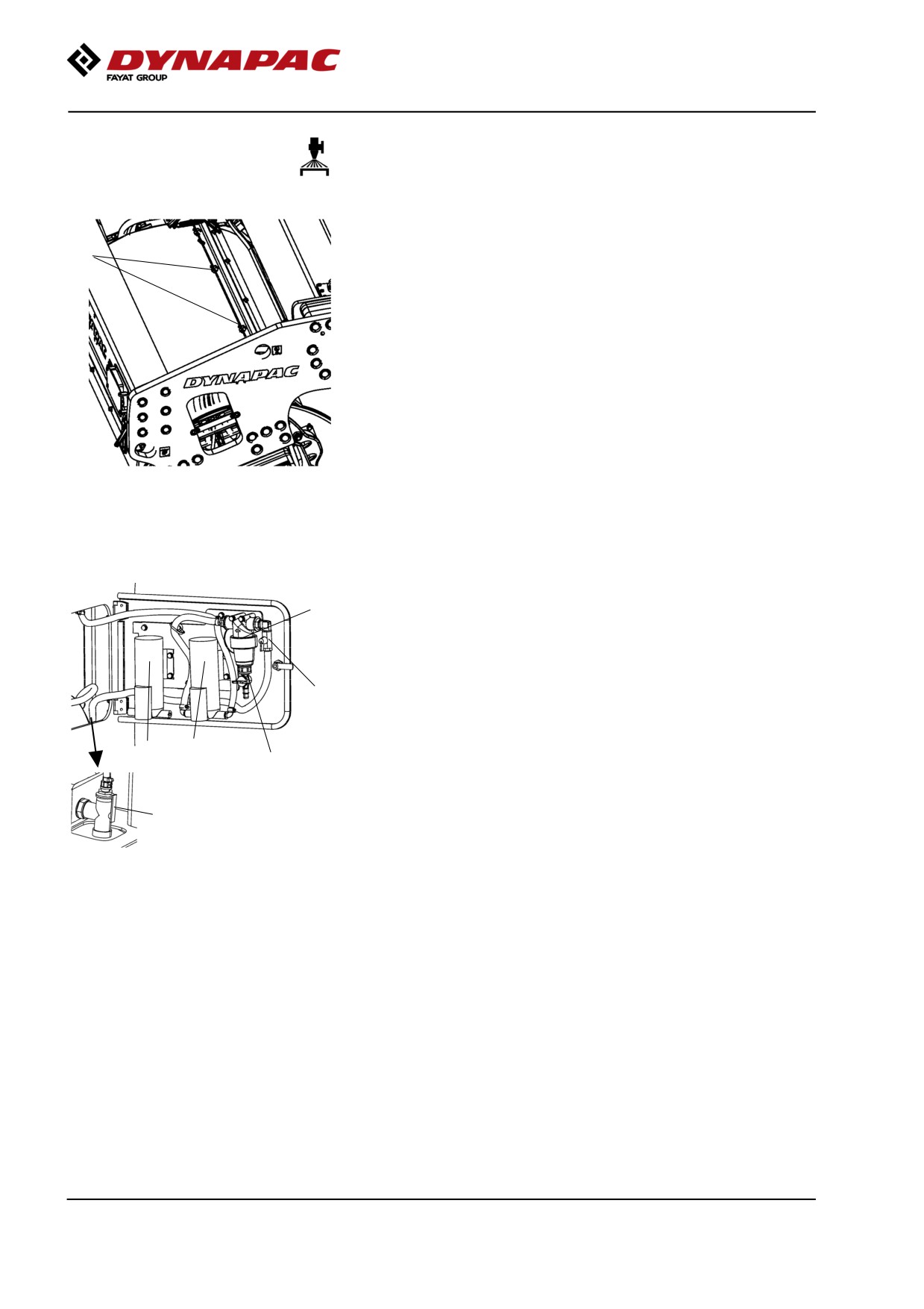
Sprinkler system/Drum
Check
Start the sprinkler system and make sure that none of
the nozzles (1) are clogged. If necessary, clean
1
blocked nozzles and the coarse filter placed by the
water pump (2). See next section.
Newer machines can have sprinkler systems with dual
sprinkler pipes and sprinkler pumps as standard.
Figure. Front drum
1. Nozzle
Cleaning the coarse filter
To clean the coarse filter (1) open the drain cock (3)
1
on the filter and allow any dirt to run out.
If necessary close the cock (2) and clean the filter and
filter housing. Check that the rubber gasket in the filter
housing is intact.
2
After inspecting and cleaning, reset and start the
system to check that it works.
6
4
3
There is a drain cock (5) in the space for the pump
system. This can be used to drain the tank and the
pump system.
5
An extra pump (6) can be installed in case the
standard water pump stops working. See section for
Figure. Pump system, front frame
emergency watering.
right side
1. Coarse filter
To drain the complete sprinkler system, see section for
2. Stop cock
Watering system - Draining, 2,000 h.
3. Drain cock kran, filter
4. Water pump
5. Drain cock
6. Extra pump (optional)
114
Maintenance, 10h
Sprinkler system/Drum
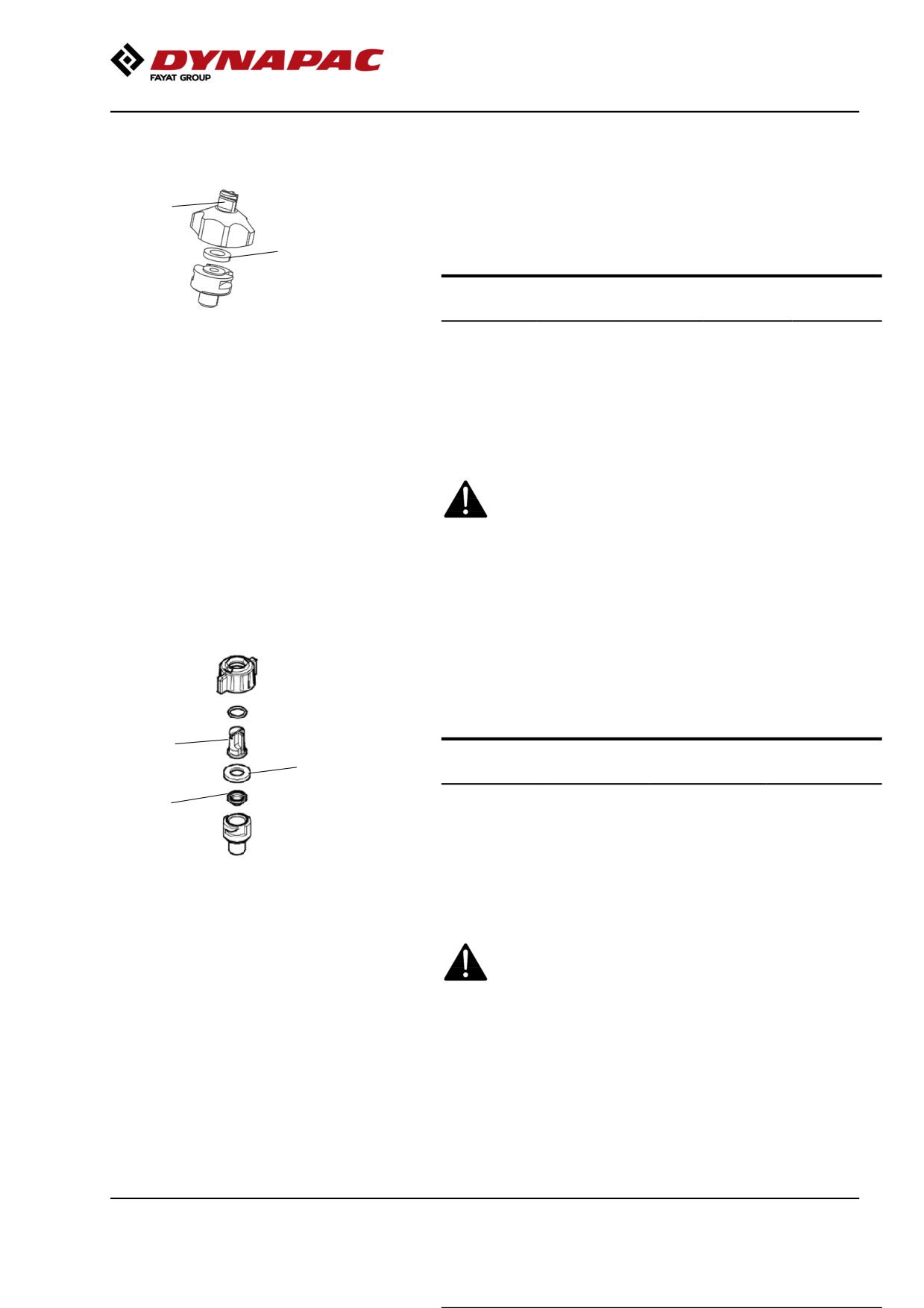
Cleaning of sprinkler nozzle
Dismantle the blocked nozzle by hand.
1
Blow the nozzle and fine filter (1) clean using
2
compressed air. Alternatively, fit replacement parts
and clean the blocked parts later on.
Nozzle
Colour
Ø (mm) l/min
gal/min
(2.0 bar)
(40 psi)
Figure. Nozzle
Standard
yellow
0.8
0.63
0.20
1. Sleeve, nozzle, filter
Option
blue
1.0
1.00
0.31
2. Packing
Option
red
1.2
1.25
0.39
Option
brown
1.3
1.63
0.50
After inspecting and carrying out any necessary
cleaning, start the system and check that it works.
Wear protective goggles when working with
compressed air.
Sprinkler system/Drum
Cleaning of sprinkler nozzle
Dismantle the blocked nozzle by hand.
Blow the nozzle (1) and fine filter (3) clean using
compressed air. Alternatively, fit replacement parts
and clean the blocked parts later on.
1
Nozzle
Colour
l/min (at 2.0
gal/min (at
2
bar)
40 psi)
Standard
yellow
0.63
0.20
3
Option
blue
0.98
0.30
Option
red
1.31
0.40
Fig. Nozzle
Option
brown
1.63
0.50
1. Nozzle
2. Gasket
3. Filter
After inspecting and carrying out any necessary
cleaning, start the system and check that it works.
Wear protective goggles when working with
compressed air.
115
Maintenance, 10h
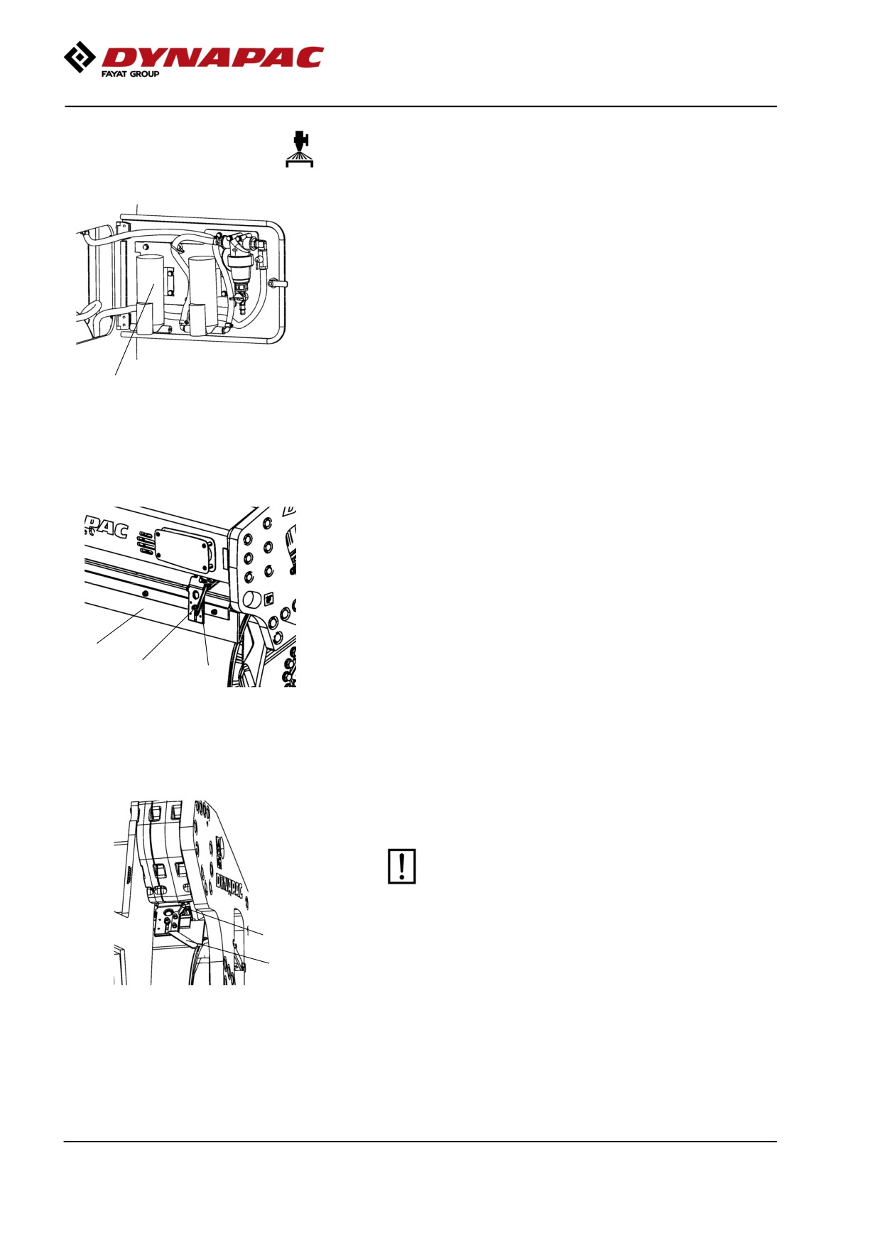
Emergency watering (Accessory) - Extra pump
in pump system
If the water pump stops, an extra pump will keep the
sprinkler system in operation.
Connect the electric cable and water hoses to the
extra pump instead of the standard pump.
The water hoses are connected to the pump with quick
couplings to simplify draining and where appropriate
replacement to a reserve pump (option).
1
Newer machines can have sprinkler systems with dual
Figure. Panel on right side of front
sprinkler pipes and sprinkler pumps as standard.
frame
1. Extra pump
Scrapers, spring-action
Check
Make sure that the scrapers are undamaged.
Release with the arm (1).
Loosen the screws (3) to adjust the scraper blade up
2
or down.
3
1
Figure. Outer scrapers
1. Release arm
2. Scraper blade
3. Adjusting screw
Asphalt remnants can accumulate on the scraper and
affect the contact force. Clean when necessary.
The scrapers must be retracted from the drum
during transport driving.
1
2
Figure. Inner scrapers
1. Release arm
2. Lifting handle
116
Maintenance, 10h
Scrapers
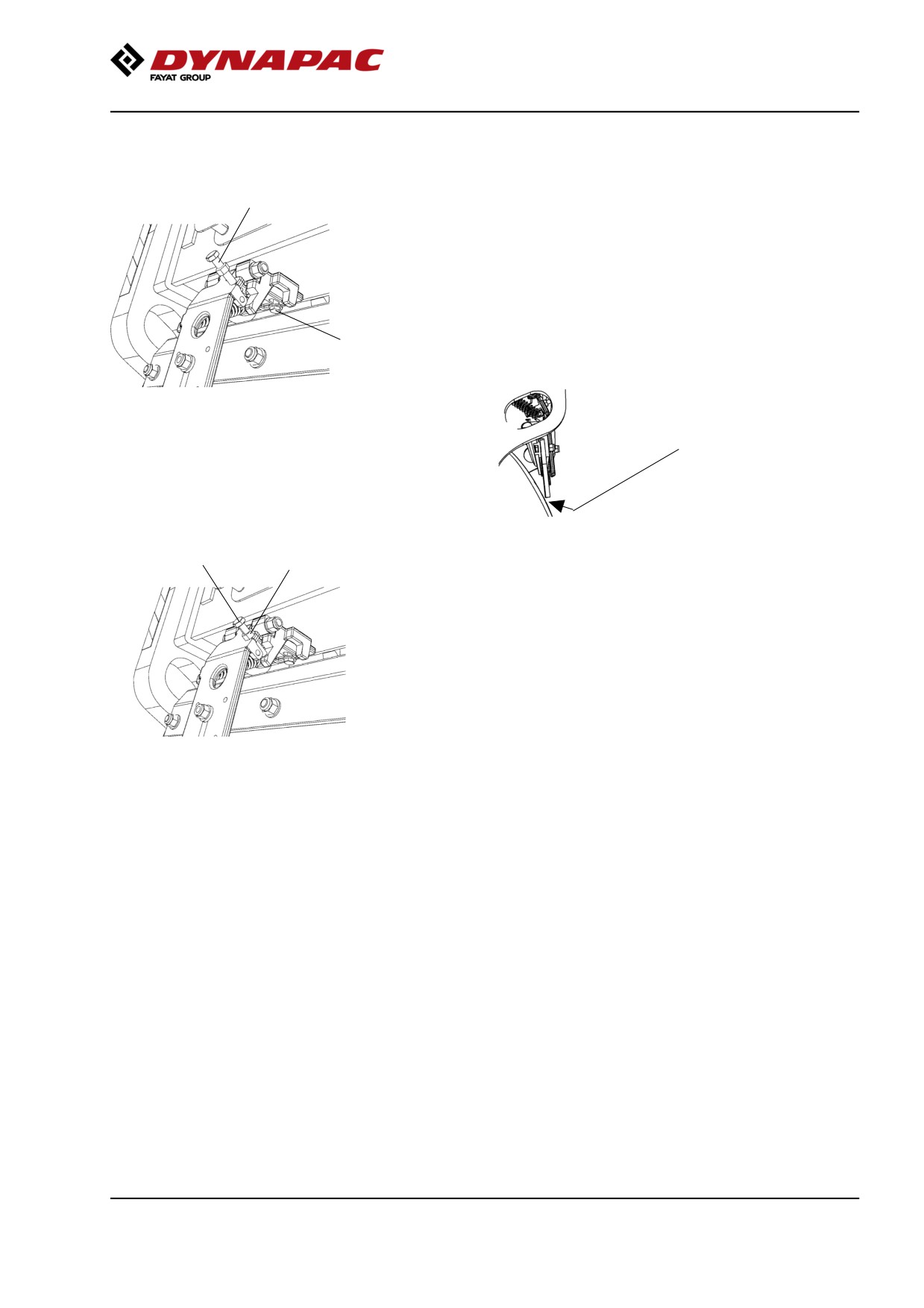
Setting - Adjustment
2
Release the retaining unit (1) for the scraper bracket
and unscrew the adjusting screw (2) to release.
Push in the scraper bracket and tighten.
Adjust the screw (2) so that the scraper blade lies
approx. 2 mm (0.08 in) from the drum on the same
side as the screw.
1
Adjust the scraper bracket in or out on the other side
so that there is an equal gap between the scraper
blade and drum, and tighten the retaining unit (1).
1-2 mm
(0.04-0.08 in)
2
3
The adjusting screw (2) is adjusted until the scraper
blade has a gap of approx. 1 mm (0.04 in) to the roller,
or lies loosely on the roller, along its entire length.
Tighten the lock nut (3).
Figure. Scraper setting
1. Retaining unit
2. Adjusting screw
3. Lock nut
117
Maintenance, 10h
118
Maintenance - 50h
Maintenance - 50h
Every 50 hours of operation (Weekly)
Park the roller on a level surface.
The engine must be switched off and the
parking brake activated when checking or
adjusting the roller, unless otherwise specified.
Ensure that there is good ventilation (air
extraction) if the engine is run indoors.
Risk of carbon monoxide poisoning.
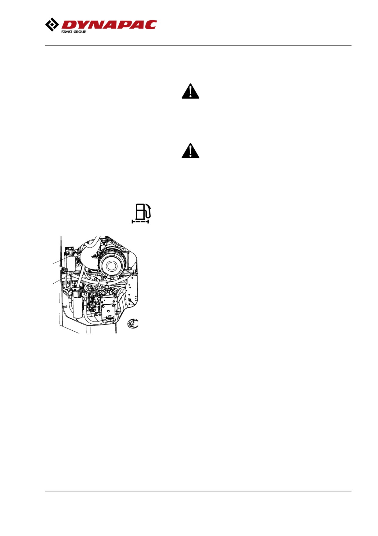
Fuel filter - Draining
Unscrew the drain plug (1) at the bottom of the fuel
filter.
2
With the aid of the secondary hand-operated pump,
1
make certain that all sediment comes out. See
Cummins service manual.
Tighten the drain plug as soon as uncontaminated fuel
runs out.
Figure. Fuel filter
1. Drain plug
2. Hand pump
119
Maintenance - 50h
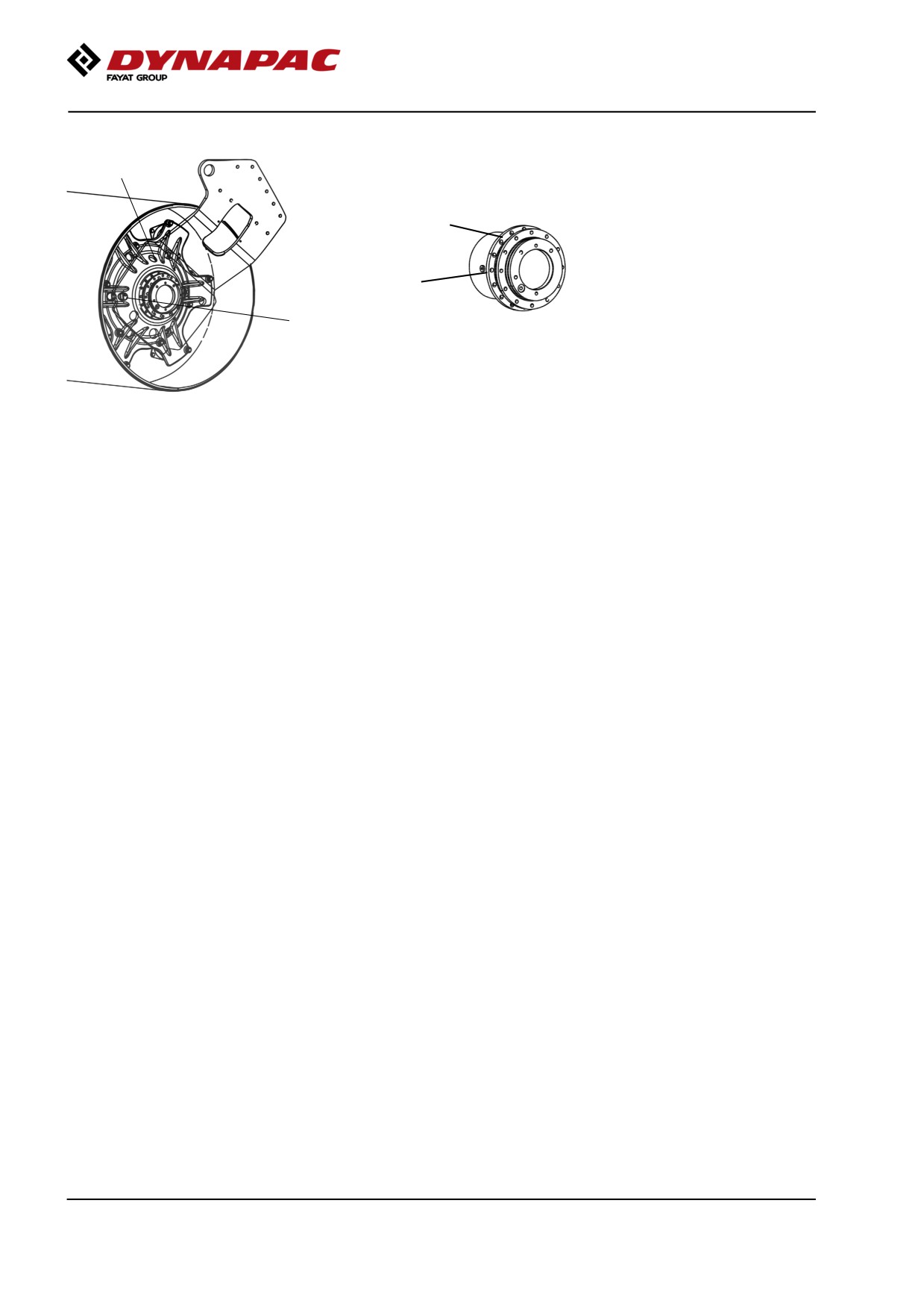
Drum gear - Checking the oil level
2
Move the machine until the inspection/filling holes are
in position for filling.
2
1
Fig. Drum gear
1
Refill with new oil. Use transmission oil according to
Fig. Oil level check - drum gear
the lubricant specification.
1. Level plug
2. Filling plug
Ensure that the oil level reaches up to the lower edge
of the plug hole.
Clean and refit the plugs.
120
Maintenance measures - 250 h
Maintenance measures - 250 h
Every 250/750/1250/1750
hours of operation
(every 3 months)
Park the roller on a level surface.
The engine must be switched off and the
parking brake activated when checking or
adjusting the roller, unless otherwise specified.
Ensure that there is good ventilation (air
extraction) if the engine is run indoors.
Risk of carbon monoxide poisoning.
Diesel engine
Oil change
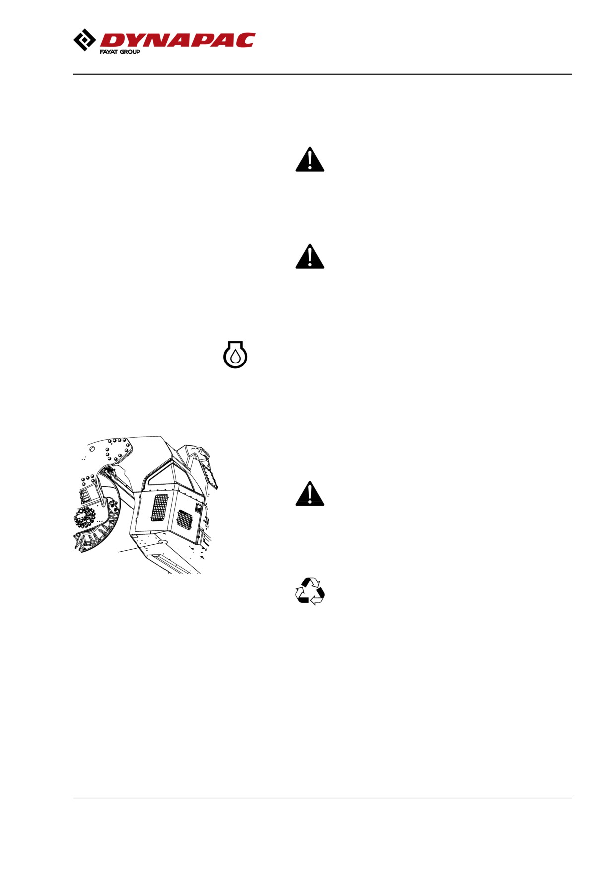
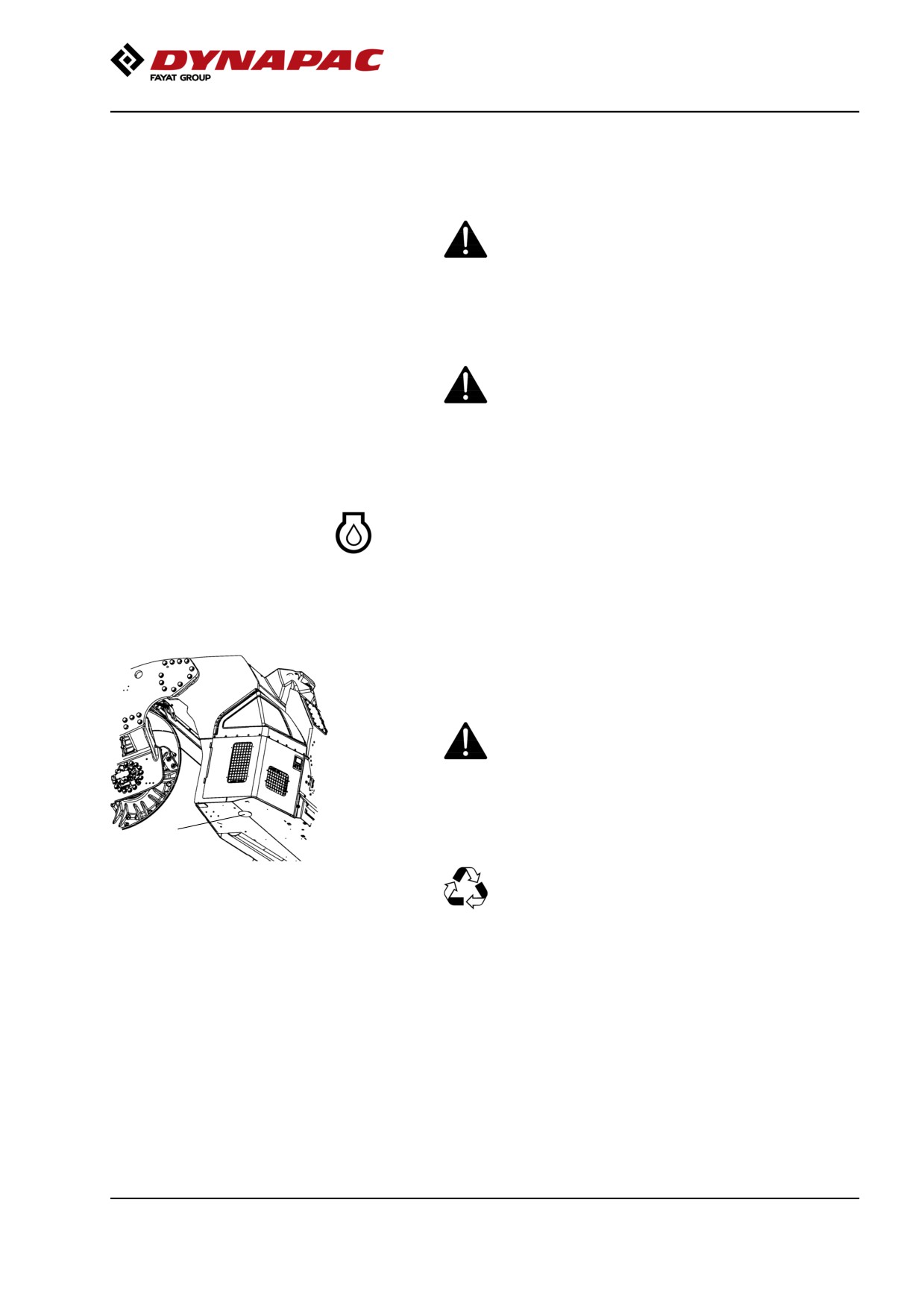
The engine's oil drain plug is located under the rear
frame on the machine on the right side.The drain plug
is accessed by first removing the rubber plug on the
underside of the frame.
Drain the oil when the engine is warm. Place a
receptacle that holds at least 14 liters (15 qts) under
the drain plugs.
Take great care when draining engine oil. Wear
protective gloves and goggles.
1
Unscrew the drain plug (1). Allow all the oil to drain out
and refit the plug.
Deliver the drain oil for environmentally correct
Figure. Underside of rear frame
handling.
1. Oil draining of diesel engine
Fill with fresh engine oil, see Lubricant specification or
the engine manual for the correct grade of oil.
Fill with the requisite volume of engine oil. See
technical specifications before starting the machine.
Allow the engine to idle for a few minutes, and then
switch off the engine.
Check the dipstick to ensure that the engine oil level is
correct. Refer to the engine manual for details. Top up
with oil if necessary to the max mark on the dipstick.
121
Maintenance measures - 250 h
Engine
Replacing oil filter
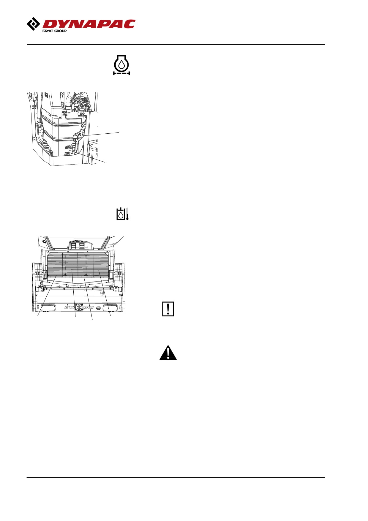
Check the dipstick (2) to ensure that the engine oil
level is correct. Refer to the engine manual for details.
2
The oil filter (1) can be accessed via the right engine
compartment door.
1
See the engine manual for information about replacing
the filter.
Fig. Engine compartment, right side
1. Oil filter
2. Dipstick
Hydraulic fluid cooler
Checking - Cleaning
The water and hydraulic fluid coolers are accessible
when the cooler grill (4) is removed.
Make sure that the air flow through the cooler is
unobstructed. Dirty coolers are blown clean with
compressed air or washed clean using a
high-pressure water cleaner.
Take care when using a high-pressure water jet.
Do not hold the nozzle too near the cooler.
3
1
2
4
Figure. Cooler
1. Charge air cooler
2. Water cooler
3. Hydraulic fluid cooler
Wear protective goggles when working with
4. Cooler grill
compressed air or high-pressure water jets.
122
Maintenance measures - 250 h
Battery
- Check condition
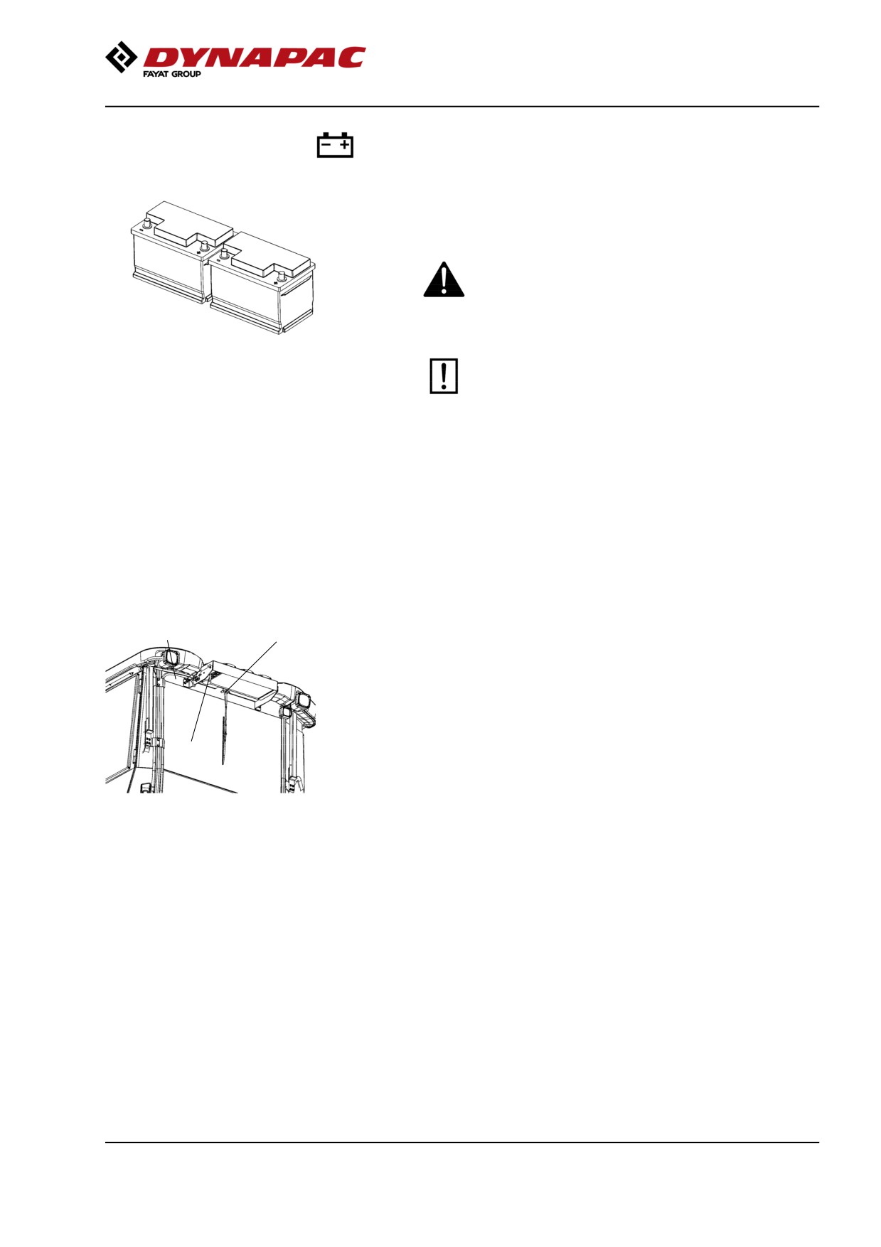
The batteries are sealed and maintenance-free.
Make sure there is no open flame in the vicinity
when checking the electrolyte level. Explosive gas
is formed when the alternator charges the battery.
Fig. Batteries
When disconnecting the battery, always
disconnect the negative cable first. When
connecting the battery, always connect the
positive cable first.
The cable shoes should be clean and tightened.
Corroded cable shoes should be cleaned and
greased with acid-proof Vaseline.
Wipe the top of the battery.
Air conditioning (Optional)
- Inspection
1
2
Inspect refrigerant hoses and connections and make
sure that there are no signs of an oil film that can
indicate a refrigerant leakage.
If there is a signifcant loss of cooling capacity, clean
the condensor element (2) on the rear edge of the cab
roof.
3
Fig. Air conditioning
1. Refrigerant hoses
2. Condensor element
3. Drying filter
123
Maintenance measures - 250 h
Air conditioning (Optional)
Drying filter - Inspection
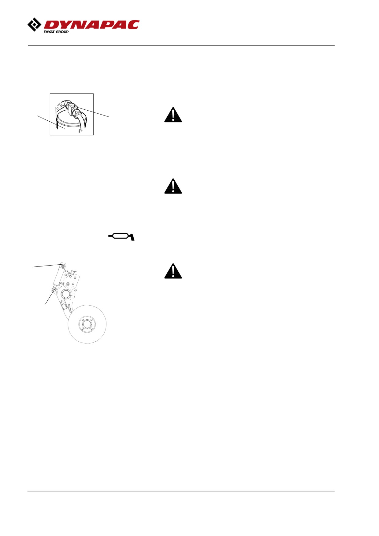
With the unit in operation, check using the sight glass
(1) that bubbles are not visible on the drying filter.
Park the roller on a level surface, chock the wheels
2
and activate the parking brake.
1
Figure. Drying filter
The filter is placed at the top of the rear part of the cab
1. Sight glass
2. Filter holder
roof.
If bubbles are visible through the sight glass, this
indicates that the refrigerant level is too low. Stop the
unit to avoid risking damage. Fill up with refrigerant.
The refrigerant circuit is only to be worked on by
authorized companies.
Edge cutter (Optional)
- Lubrication
Refer to the operation section for information
2
on how to operate the edge cutter.
1
Grease the two points as shown in the figure.
Grease should always be used for lubrication.
See the lubricant specifications.
Grease all bearing points with five strokes
Fig. Two grease points for lubricating
of a hand-operated grease gun.
the edge cutter
124
Maintenance measures - 500 h
Maintenance measures - 500 h
Every 500/1500
hours of operation (every six
months)
Park the roller on a level surface.
The engine must be switched off and the
parking brake activated when checking or
adjusting the roller, unless otherwise specified.
Ensure that there is good ventilation (air
extraction) if the engine is run indoors.
Risk of carbon monoxide poisoning.
Diesel engine
Oil change
The engine's oil drain plug is located under the rear
frame on the machine on the right side.The drain plug
is accessed by first removing the rubber plug on the
underside of the frame.
Drain the oil when the engine is warm. Place a
receptacle that holds at least 14 liters (15 qts) under
the drain plugs.
Take great care when draining engine oil. Wear
protective gloves and goggles.
1
Unscrew the drain plug (1). Allow all the oil to drain out
and refit the plug.
Deliver the drain oil for environmentally correct
Figure. Underside of rear frame
handling.
1. Oil draining of diesel engine
Fill with fresh engine oil, see Lubricant specification or
the engine manual for the correct grade of oil.
Fill with the requisite volume of engine oil. See
technical specifications before starting the machine.
Allow the engine to idle for a few minutes, and then
switch off the engine.
Check the dipstick to ensure that the engine oil level is
correct. Refer to the engine manual for details. Top up
with oil if necessary to the max mark on the dipstick.
125
Maintenance measures - 500 h
Engine
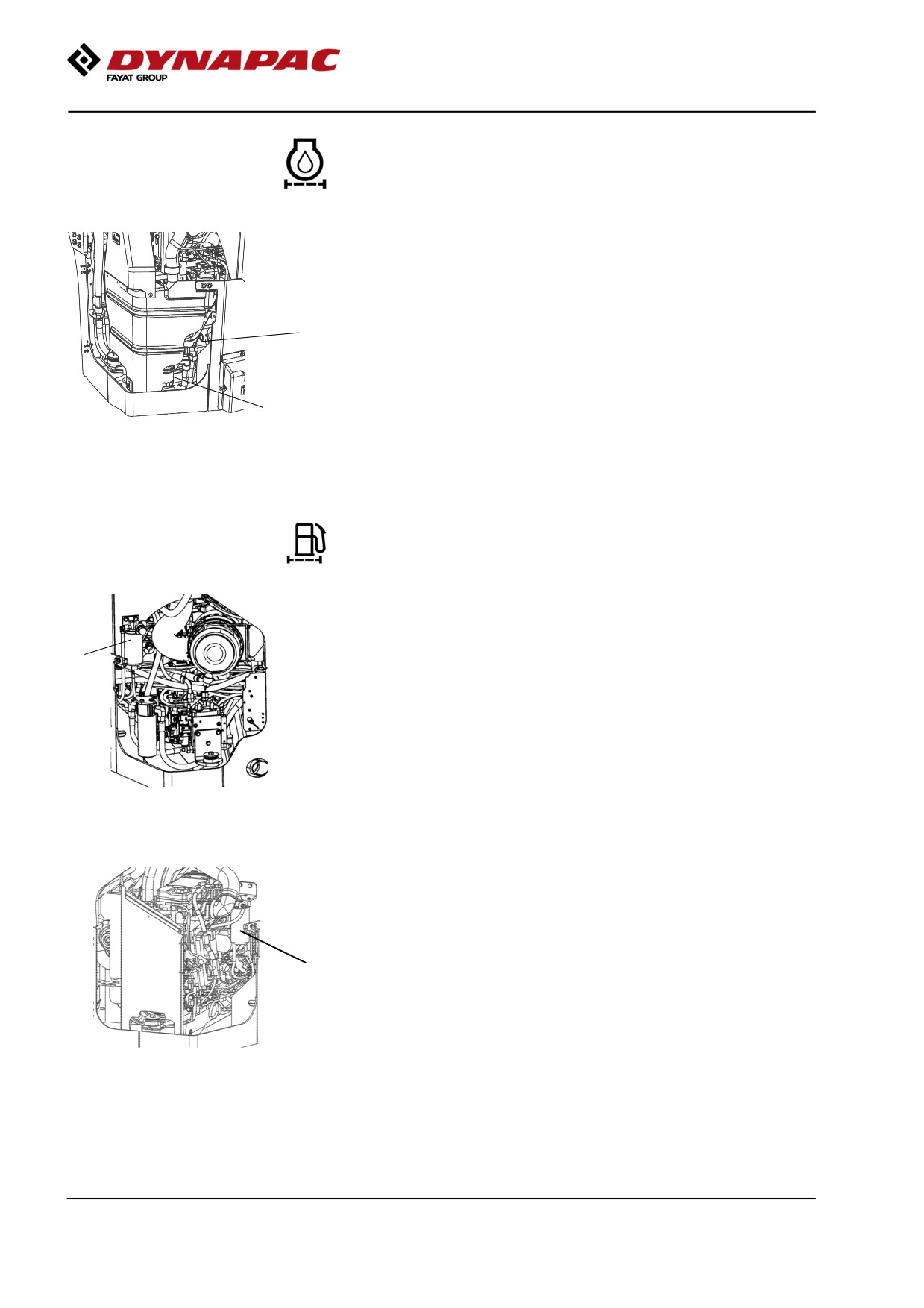
Replacing oil filter
Check the dipstick (2) to ensure that the engine oil
level is correct. Refer to the engine manual for details.
2
The oil filter (1) can be accessed via the right engine
compartment door.
1
See the engine manual for information about replacing
the filter.
Fig. Engine compartment, right side
1. Oil filter
2. Dipstick
The engine fuel filter - replacement/cleaning
The fuel filter is placed on the left side of the engine
compartment.
1
Unscrew the bottom and drain off any water, and then
replace the filter unit.
Figure. Engine compartment, left side
1. Prefilter
Replace the fuel filter, located on the right side of the
engine compartment.
Start the engine and check that the filter is well sealed.
1
Figure. Engine compartment, right
side.
1. Fuel filter
126
Maintenance measures - 500 h
Hydraulic fluid cooler
Checking - Cleaning
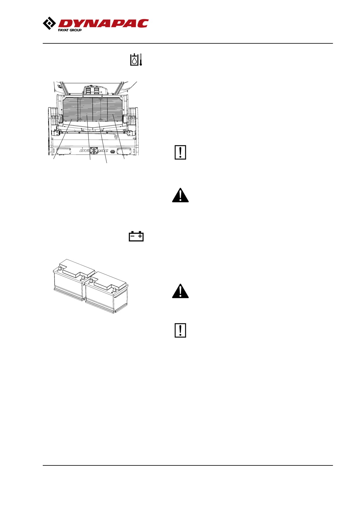
The water and hydraulic fluid coolers are accessible
when the cooler grill (4) is removed.
Make sure that the air flow through the cooler is
unobstructed. Dirty coolers are blown clean with
compressed air or washed clean using a
high-pressure water cleaner.
Take care when using a high-pressure water jet.
Do not hold the nozzle too near the cooler.
3
2
1
4
Figure. Cooler
1. Charge air cooler
2. Water cooler
3. Hydraulic fluid cooler
Wear protective goggles when working with
4. Cooler grill
compressed air or high-pressure water jets.
Battery
- Check condition
The batteries are sealed and maintenance-free.
Make sure there is no open flame in the vicinity
when checking the electrolyte level. Explosive gas
is formed when the alternator charges the battery.
Fig. Batteries
When disconnecting the battery, always
disconnect the negative cable first. When
connecting the battery, always connect the
positive cable first.
The cable shoes should be clean and tightened.
Corroded cable shoes should be cleaned and
greased with acid-proof Vaseline.
Wipe the top of the battery.
127
Maintenance measures - 500 h
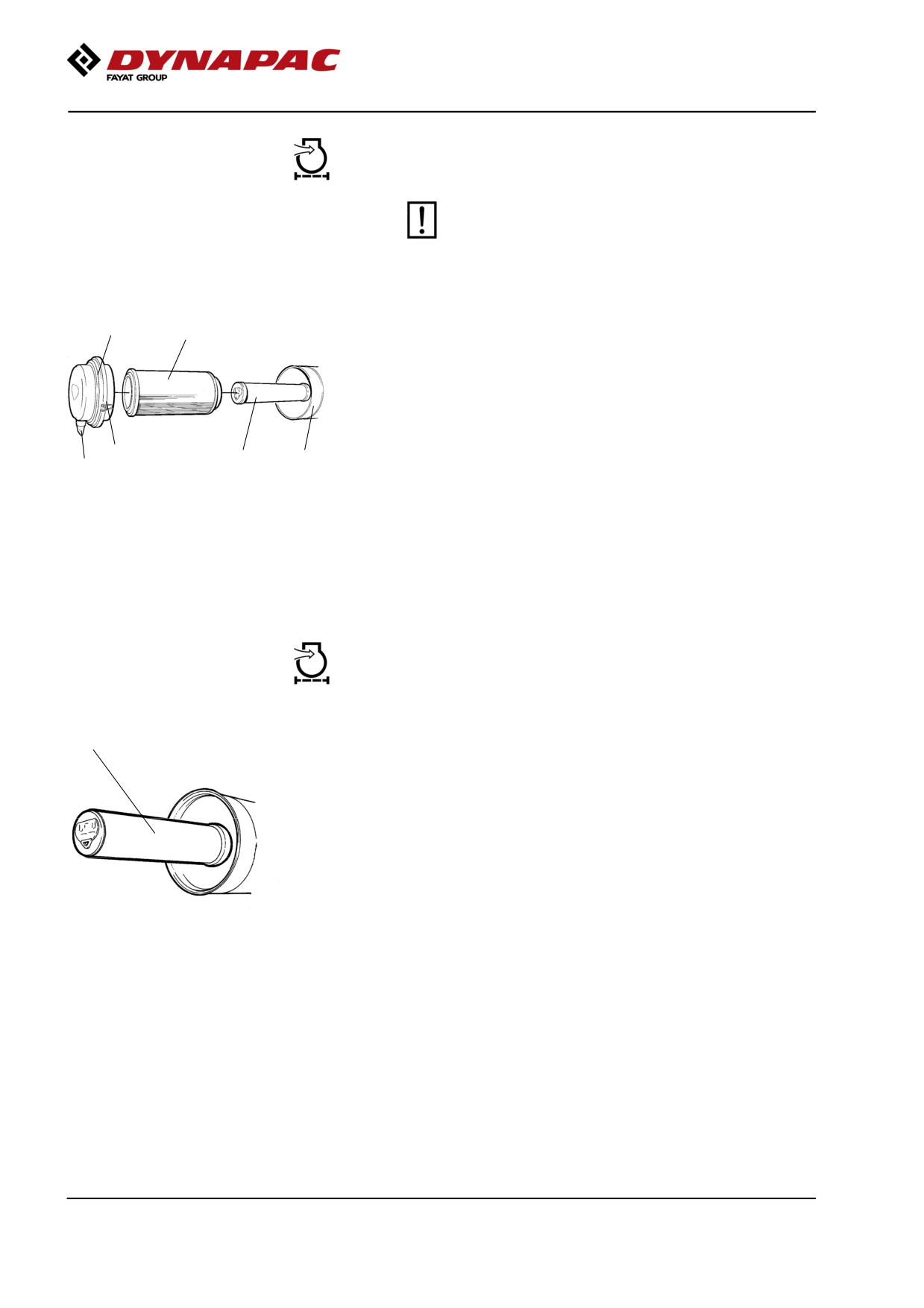
Air cleaner
Checking - Change the main air filter
Change the air cleaner's main filter when the
warning lamp on the display lights when the
diesel engine is operating at full speed.
2
3
Release the clips (1), pull off the cover (2),
and pull out the main filter (3).
Do not remove the backup filter (4).
Clean the air cleaner if necessary.
See section Air cleaner - Cleaning.
When replacing the main filter (3), insert a new filter
1
4
5
6
and refit the air cleaner in the reverse order.
Fig. Air cleaner
Check the condition of the dust valve (6).
1. Clips
Replace if necessary.
2. Cover
3. Main filter
4. Backup filter
When refitting the cover, make sure that the dust valve
5. Filter housing
is positioned downwards.
6. Dust valve
Backup filter - Change
1
Change the backup filter with a new filter after every
second replacement of the main filter.
To change the backup filter (1), pull the old filter out of
its holder, insert a new filter and reassemble the air
cleaner in the reverse order.
Clean the air cleaner if necessary, see section Air
cleaner - Cleaning.
Fig. Air filter
1. Backup filter
128
Maintenance measures - 500 h
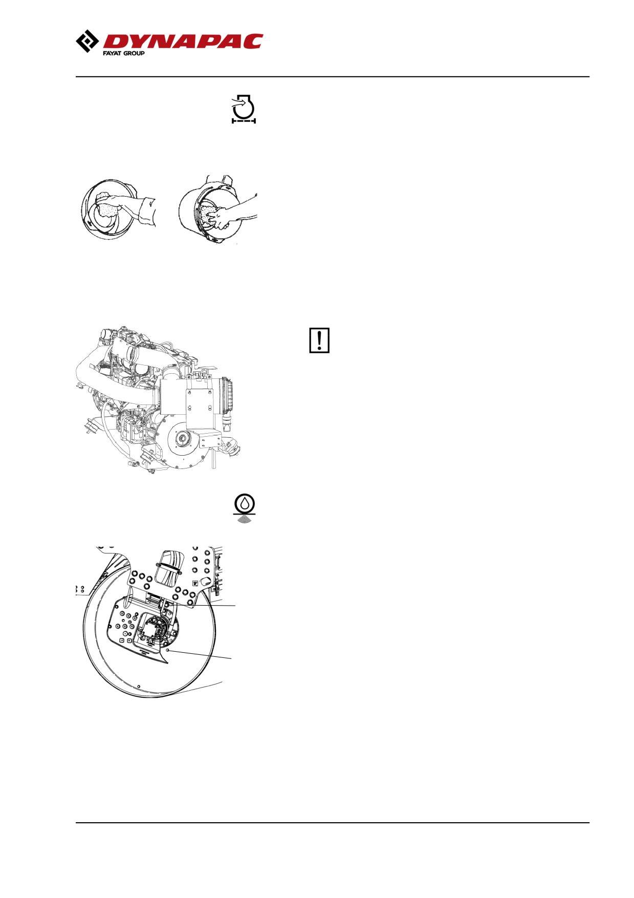
Air cleaner
- Cleaning
Wipe clean on both sides of the outlet
pipe.
Wipe clean the inside of the cover (2) and the filter
housing (5). See the previous illustration.
Wipe also both surfaces for the outlet pipe; see
adjacent figure.
Inner edge of
Outer edge of outlet
outlet pipe.
pipe.
Check that the hose clamps between the filter
housing and the suction hose are tight and that
the hoses are intact. Inspect the entire hose
system, all the way to the engine.
Drum - oil level
Inspection - filling
Position the roller with the filler plug (1), the large plug,
at the highest point in its rotation.
Wipe clean around the level plug (2), the small plug,
and remove the plug.
1
Make sure that the oil level is up to the lower edge of
the hole. Top off with fresh oil if the level is low. Use oil
as specified in the lubricants specification.
2
When removing the filler plug, wipe any metal
accumulated on the plug magnet off. Make sure that
plug seals are intact and replace with new seals if not.
Fig. Drum, vibration side
Refit the plugs and check that they are tight by driving
1. Filler plug
2. Level plug
the roller and then rechecking.
129
Maintenance measures - 500 h
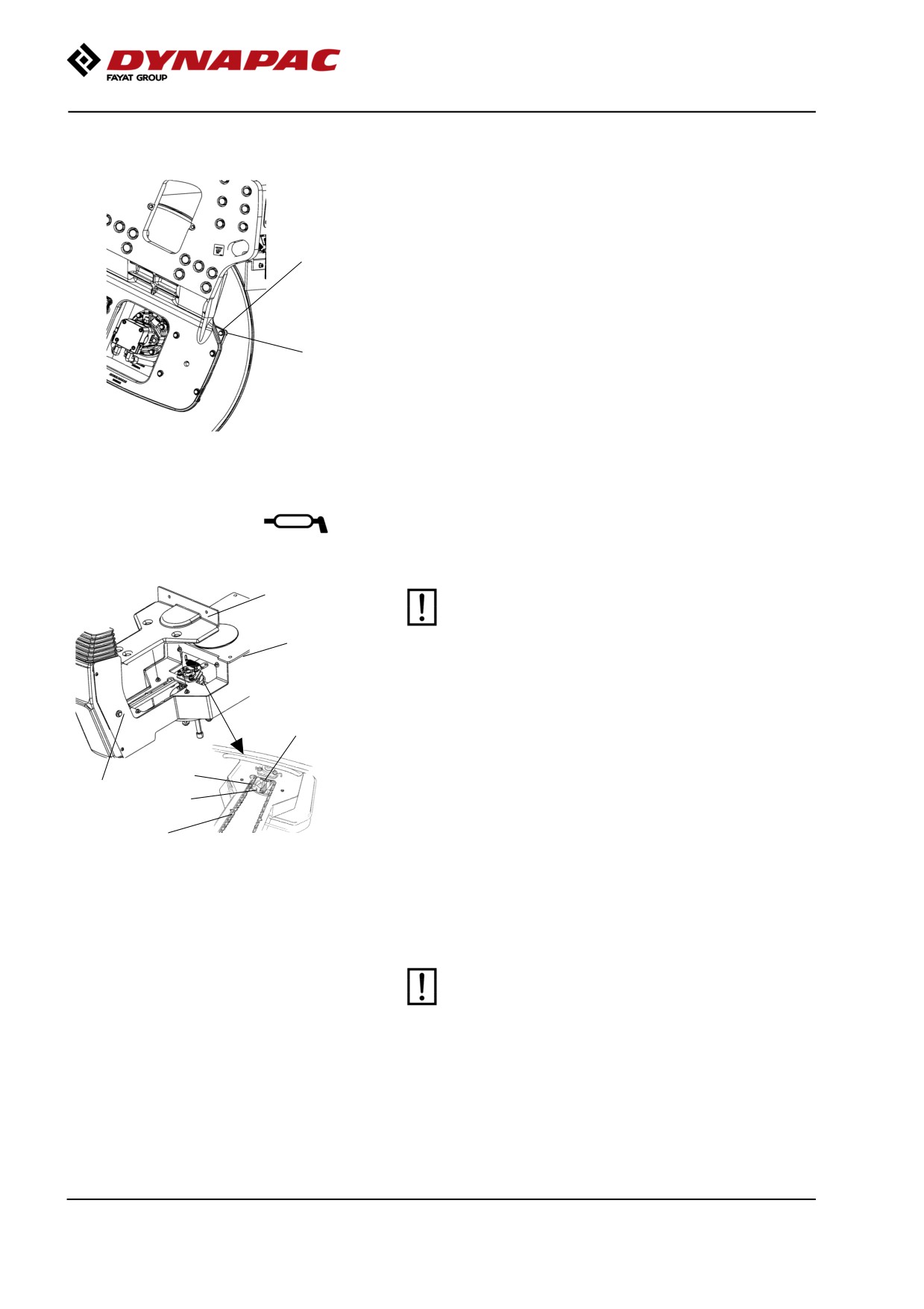
Rubber elements and attachment screws
Check
Check all rubber elements (1). Replace all elements if
25% or more than 25% of the number on one side of
the drum have cracks deeper than 10-15 mm (0.4-0.6
in).
1
Check using a knife blade or pointed object.
Check also that the attachment screws (2) are
tightened.
2
Fig. Drum, vibration side
1. Rubber element
2. Attachment screws
Seat bearing - Lubrication
5
Keep in mind that the chain is a vital part of the
steering mechanism.
6
Remove the cover (5) to access the lubrication nipple
(1). Lubricate the operator seat slew bearing with three
2
strokes of a hand-operated grease gun.
Clean and grease the chain (3) between the seat and
3
the steering column.
4
1
Also grease the seat slide rails (6).
7
If the chain is slack on the sprocket (2), loosen the
Figure. Seat bearing
screws (4) and move the steering column forward.
1. Grease nipple
Tighten the screws and check chain tension.
2. Gearwheel
3. Steering chain
No not tension the chain too tightly. It should be
4. Adjusting screw
possible to move the chain about 10 mm (0.4 in) to the
5. Cover
side with a forefinger/thumb at the marking (7) in seat
6. Slide rails
7. Marking
frame. Fit the chain lock at the bottom.
If the seat starts to be stiff when adjusting, it
should be lubricated more often than specified
here.
130
Maintenance measures - 500 h
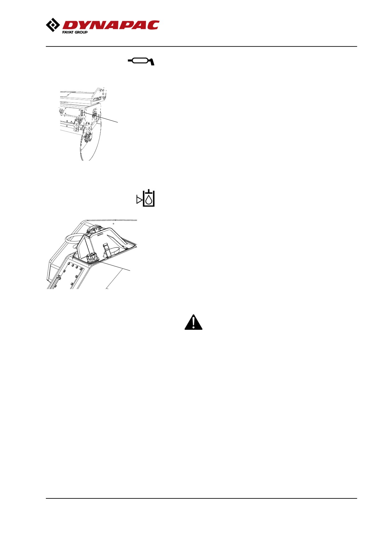
Pivot bearing (Optional) - Lubrication
Grease each nipple (1) with five strokes of a
hand-operated grease gun.
Use grease as specified in the lubricant specification.
1
Fig. Rear drum
1. Grease nipples x 4
Hydraulic reservoir cap - Check
Turn up the machine so that the tank cap is accessible
from the left side of the machine.
Unscrew and make sure that the reservoir cap is not
clogged. Air must have unobstructed passage through
the cap in both directions.
1
If passage in either direction is blocked, clean the filter
with a little diesel oil and blow through with
Figure. Rear frame front left side
compressed air until the block is removed, or replace
1. Hydraulic reservoir cap
the cap with a new one.
Wear protective goggles when working with
compressed air.
131
Maintenance measures - 500 h
Air conditioning (Optional)
- Inspection
1
2
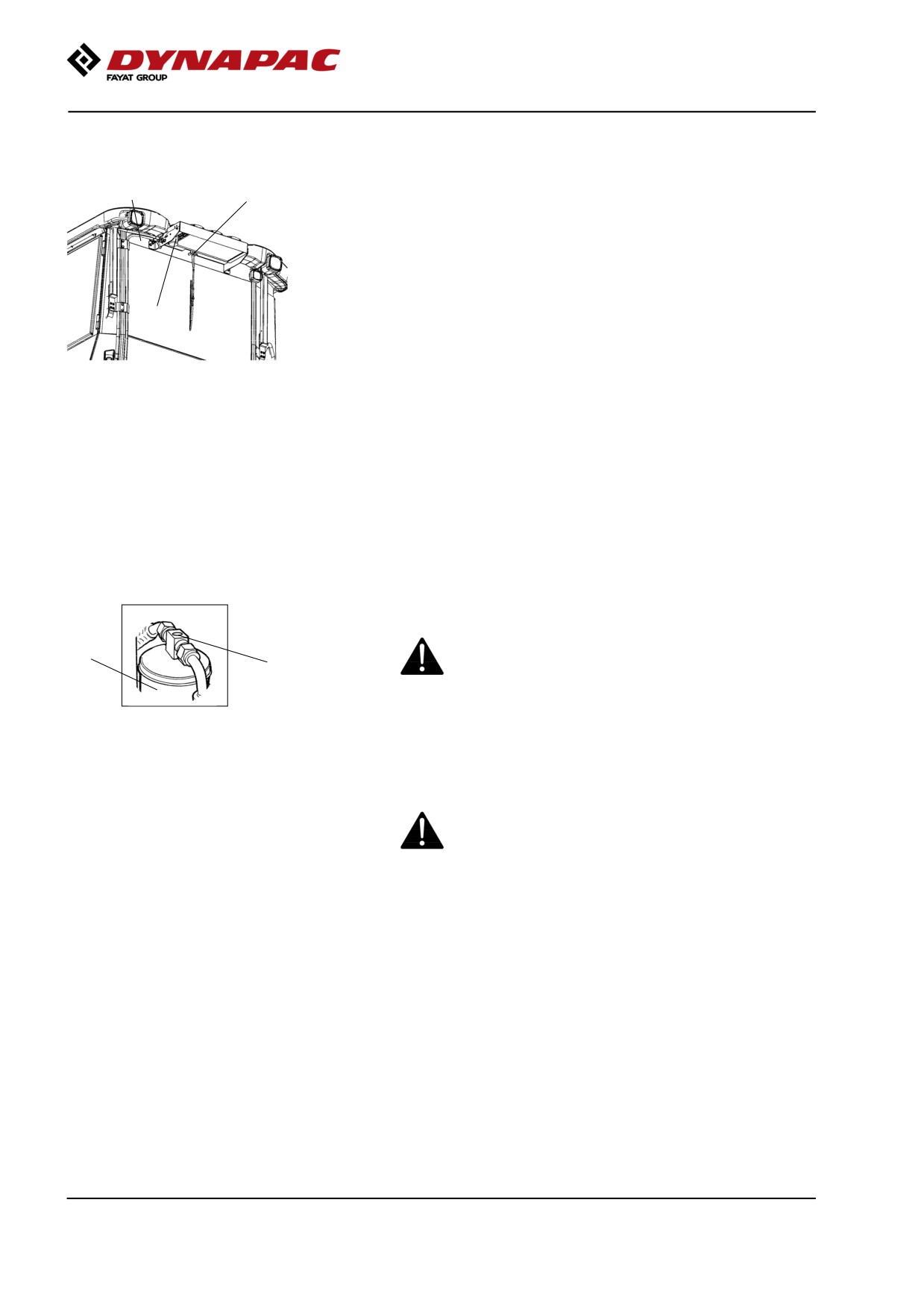
Inspect refrigerant hoses and connections and make
sure that there are no signs of an oil film that can
indicate a refrigerant leakage.
If there is a signifcant loss of cooling capacity, clean
the condensor element (2) on the rear edge of the cab
roof.
3
Fig. Air conditioning
1. Refrigerant hoses
2. Condensor element
3. Drying filter
Air conditioning (Optional)
Drying filter - Inspection
With the unit in operation, check using the sight glass
(1) that bubbles are not visible on the drying filter.
Park the roller on a level surface, chock the wheels
2
and activate the parking brake.
1
Figure. Drying filter
The filter is placed at the top of the rear part of the cab
1. Sight glass
2. Filter holder
roof.
If bubbles are visible through the sight glass, this
indicates that the refrigerant level is too low. Stop the
unit to avoid risking damage. Fill up with refrigerant.
The refrigerant circuit is only to be worked on by
authorized companies.
132
Maintenance measures - 500 h
Edge cutter (Optional)
- Lubrication
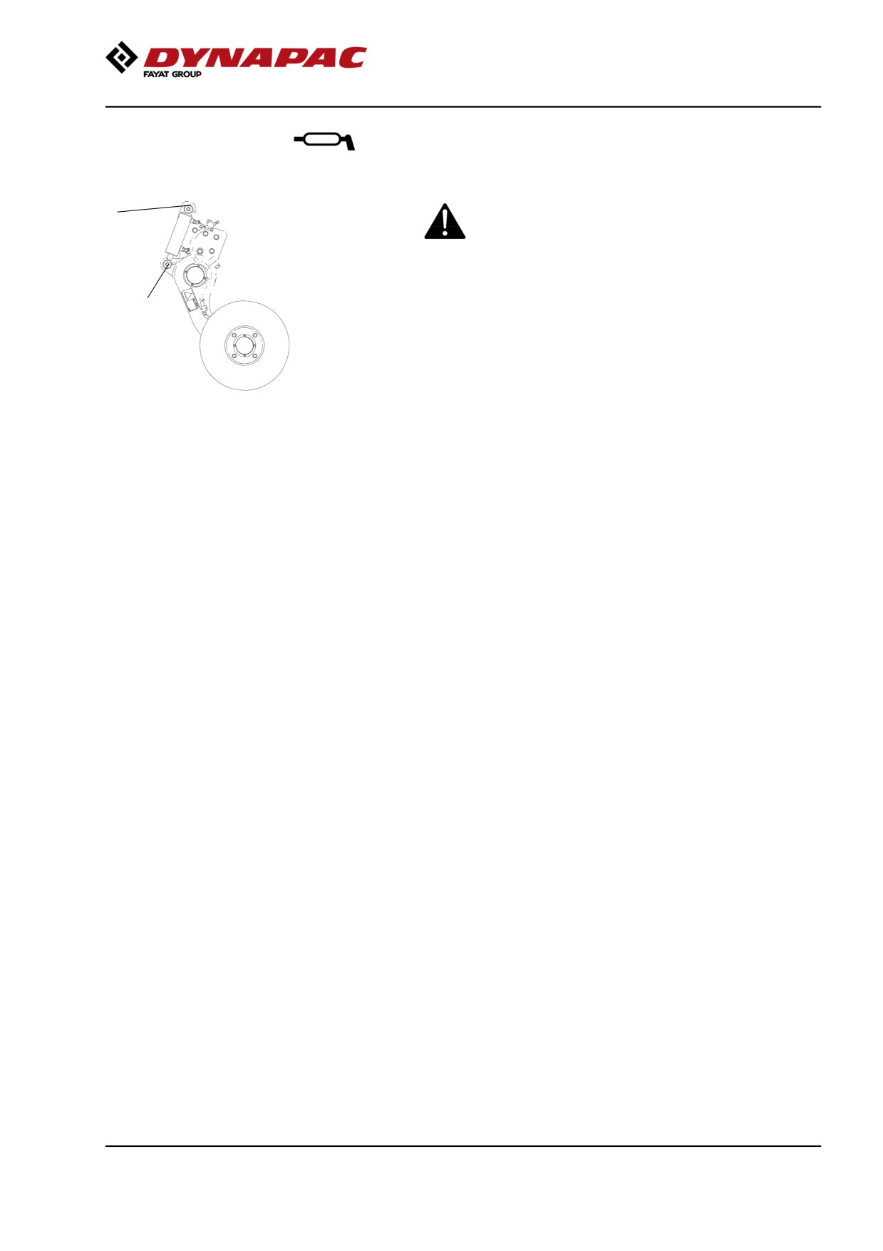
Refer to the operation section for information
2
on how to operate the edge cutter.
1
Grease the two points as shown in the figure.
Grease should always be used for lubrication.
See the lubricant specifications.
Grease all bearing points with five strokes
Fig. Two grease points for lubricating
of a hand-operated grease gun.
the edge cutter
133
Maintenance measures - 500 h
134
Maintenance - 1000h
Maintenance - 1000h
Performed after 1000 operating hours (each year)
Park the roller on a level surface.
The engine must be switched off and the
parking brake activated when checking or
adjusting the roller, unless otherwise specified.
Ensure that there is good ventilation (air
extraction) if the engine is run indoors.
Risk of carbon monoxide poisoning.
Diesel engine
Oil change
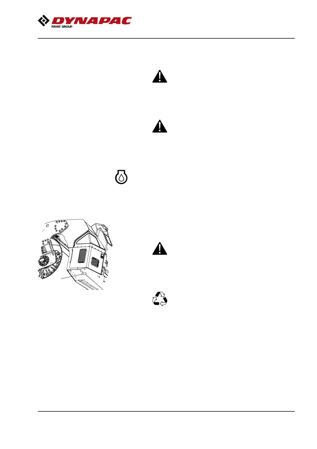
The engine's oil drain plug is located under the rear
frame on the machine on the right side.The drain plug
is accessed by first removing the rubber plug on the
underside of the frame.
Drain the oil when the engine is warm. Place a
receptacle that holds at least 14 liters (15 qts) under
the drain plugs.
Take great care when draining engine oil. Wear
protective gloves and goggles.
1
Unscrew the drain plug (1). Allow all the oil to drain out
and refit the plug.
Deliver the drain oil for environmentally correct
Figure. Underside of rear frame
handling.
1. Oil draining of diesel engine
Fill with fresh engine oil, see Lubricant specification or
the engine manual for the correct grade of oil.
Fill with the requisite volume of engine oil. See
technical specifications before starting the machine.
Allow the engine to idle for a few minutes, and then
switch off the engine.
Check the dipstick to ensure that the engine oil level is
correct. Refer to the engine manual for details. Top up
with oil if necessary to the max mark on the dipstick.
135
Maintenance - 1000h
Engine
Replacing oil filter
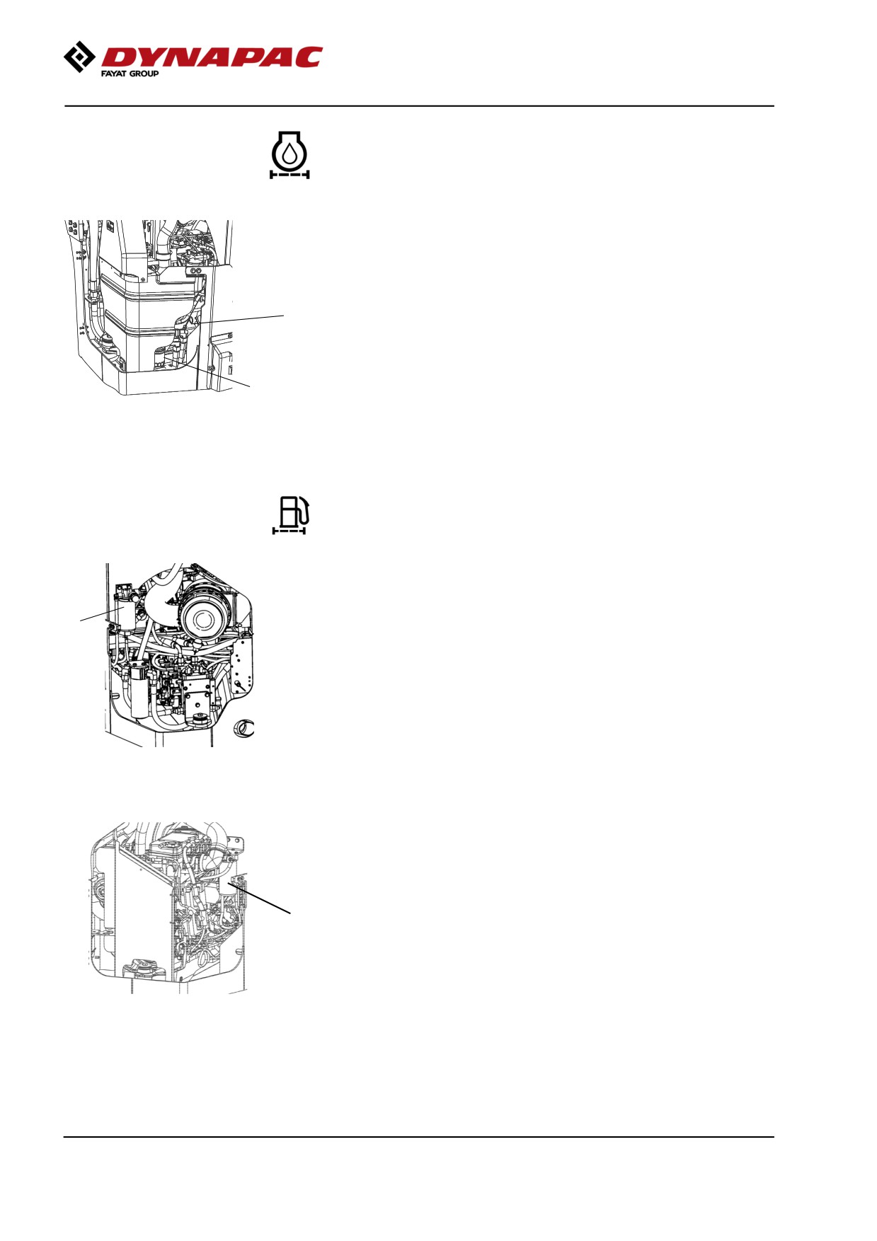
Check the dipstick (2) to ensure that the engine oil
level is correct. Refer to the engine manual for details.
2
The oil filter (1) can be accessed via the right engine
compartment door.
1
See the engine manual for information about replacing
the filter.
Fig. Engine compartment, right side
1. Oil filter
2. Dipstick
The engine fuel filter - replacement/cleaning
The fuel filter is placed on the left side of the engine
compartment.
1
Unscrew the bottom and drain off any water, and then
replace the filter unit.
Figure. Engine compartment, left side
1. Prefilter
Replace the fuel filter, located on the right side of the
engine compartment.
Start the engine and check that the filter is well sealed.
1
Figure. Engine compartment, right
side.
1. Fuel filter
136
Maintenance - 1000h
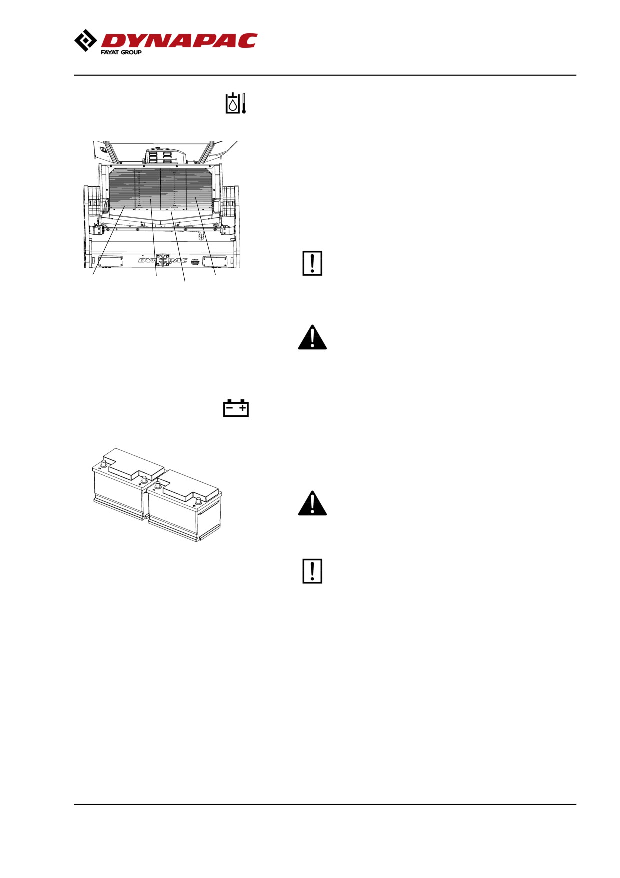
Hydraulic fluid cooler
Checking - Cleaning
The water and hydraulic fluid coolers are accessible
when the cooler grill (4) is removed.
Make sure that the air flow through the cooler is
unobstructed. Dirty coolers are blown clean with
compressed air or washed clean using a
high-pressure water cleaner.
Take care when using a high-pressure water jet.
Do not hold the nozzle too near the cooler.
3
2
1
4
Figure. Cooler
1. Charge air cooler
2. Water cooler
3. Hydraulic fluid cooler
Wear protective goggles when working with
4. Cooler grill
compressed air or high-pressure water jets.
Battery
- Check condition
The batteries are sealed and maintenance-free.
Make sure there is no open flame in the vicinity
when checking the electrolyte level. Explosive gas
is formed when the alternator charges the battery.
Fig. Batteries
When disconnecting the battery, always
disconnect the negative cable first. When
connecting the battery, always connect the
positive cable first.
The cable shoes should be clean and tightened.
Corroded cable shoes should be cleaned and
greased with acid-proof Vaseline.
Wipe the top of the battery.
137
Maintenance - 1000h
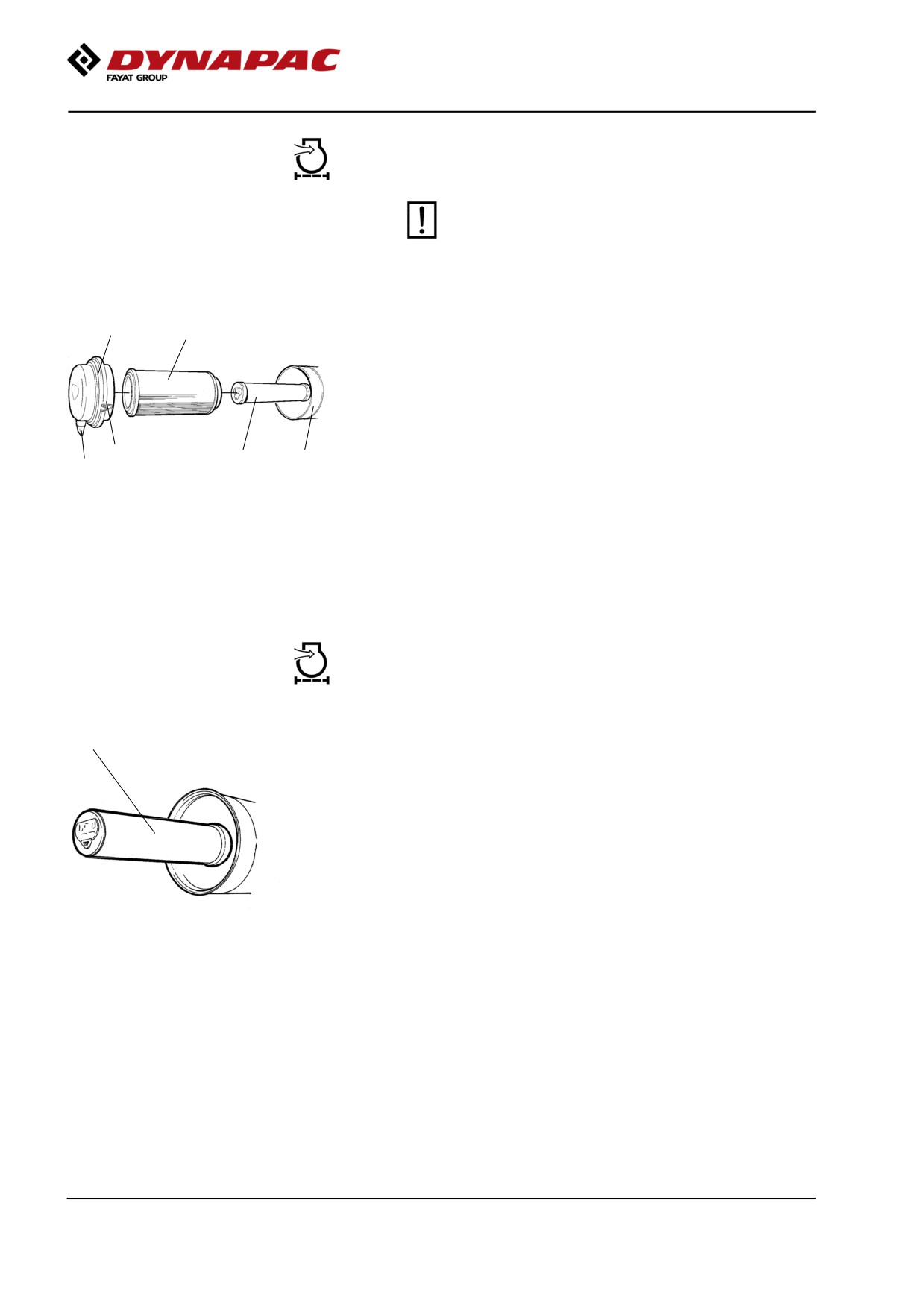
Air cleaner
Checking - Change the main air filter
Change the air cleaner's main filter when the
warning lamp on the display lights when the
diesel engine is operating at full speed.
2
3
Release the clips (1), pull off the cover (2),
and pull out the main filter (3).
Do not remove the backup filter (4).
Clean the air cleaner if necessary.
See section Air cleaner - Cleaning.
When replacing the main filter (3), insert a new filter
1
4
5
6
and refit the air cleaner in the reverse order.
Fig. Air cleaner
Check the condition of the dust valve (6).
1. Clips
Replace if necessary.
2. Cover
3. Main filter
4. Backup filter
When refitting the cover, make sure that the dust valve
5. Filter housing
is positioned downwards.
6. Dust valve
Backup filter - Change
1
Change the backup filter with a new filter after every
second replacement of the main filter.
To change the backup filter (1), pull the old filter out of
its holder, insert a new filter and reassemble the air
cleaner in the reverse order.
Clean the air cleaner if necessary, see section Air
cleaner - Cleaning.
Fig. Air filter
1. Backup filter
138
Maintenance - 1000h
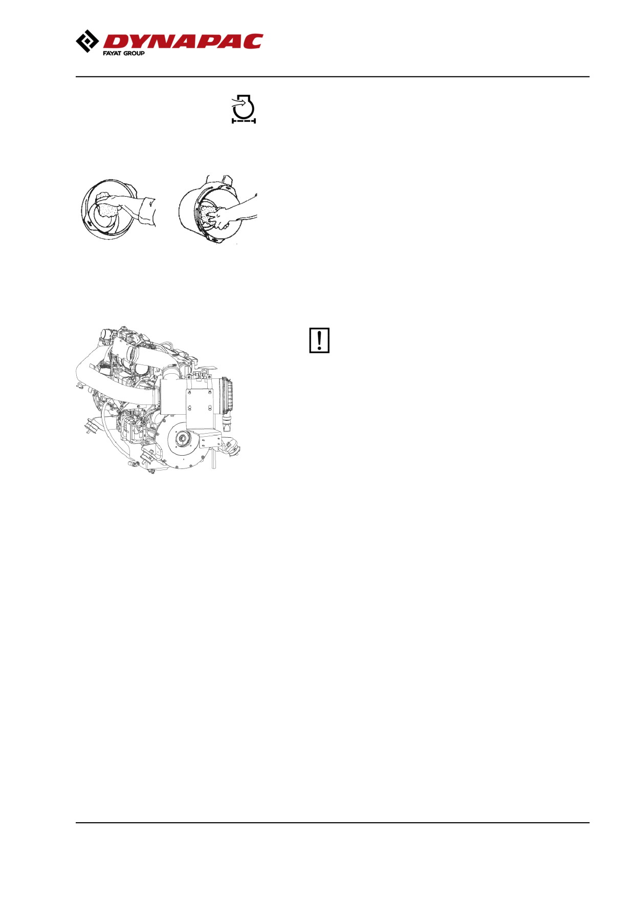
Air cleaner
- Cleaning
Wipe clean on both sides of the outlet
pipe.
Wipe clean the inside of the cover (2) and the filter
housing (5). See the previous illustration.
Wipe also both surfaces for the outlet pipe; see
adjacent figure.
Inner edge of
Outer edge of outlet
outlet pipe.
pipe.
Check that the hose clamps between the filter
housing and the suction hose are tight and that
the hoses are intact. Inspect the entire hose
system, all the way to the engine.
139
Maintenance - 1000h
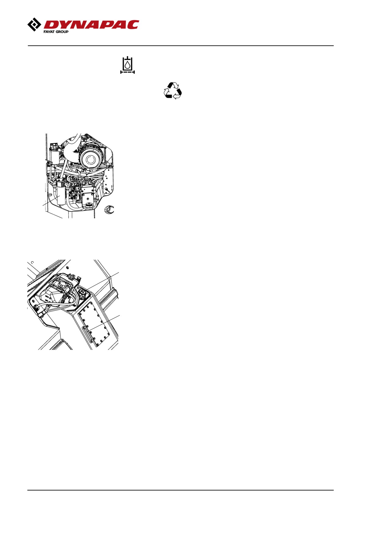
Hydraulic filter
Change
Remove the filter (1) and deliver to special waste
handling. This is a single-use filter and cannot be
cleaned.
Thoroughly clean the filter holder sealing surface.
Apply a thin coat of fresh hydraulic fluid to the rubber
gasket on the new filter.
Screw the filter on by hand, firstly until the filter gasket
makes contact with the filter base. Then rotate a
further ½ turn.
1
Figure. Engine compartment, left
1. Hydraulic fluid filter
Check the hydraulic fluid level in the sight glass (3)
2
and top off as required. See under the heading 'Every
10 hours of operation' for more information.
Start the engine and check that the filter does not leak.
3
Figure. Hydraulic tank
2. Hydraulic reservoir cap
3. Sight glass
140
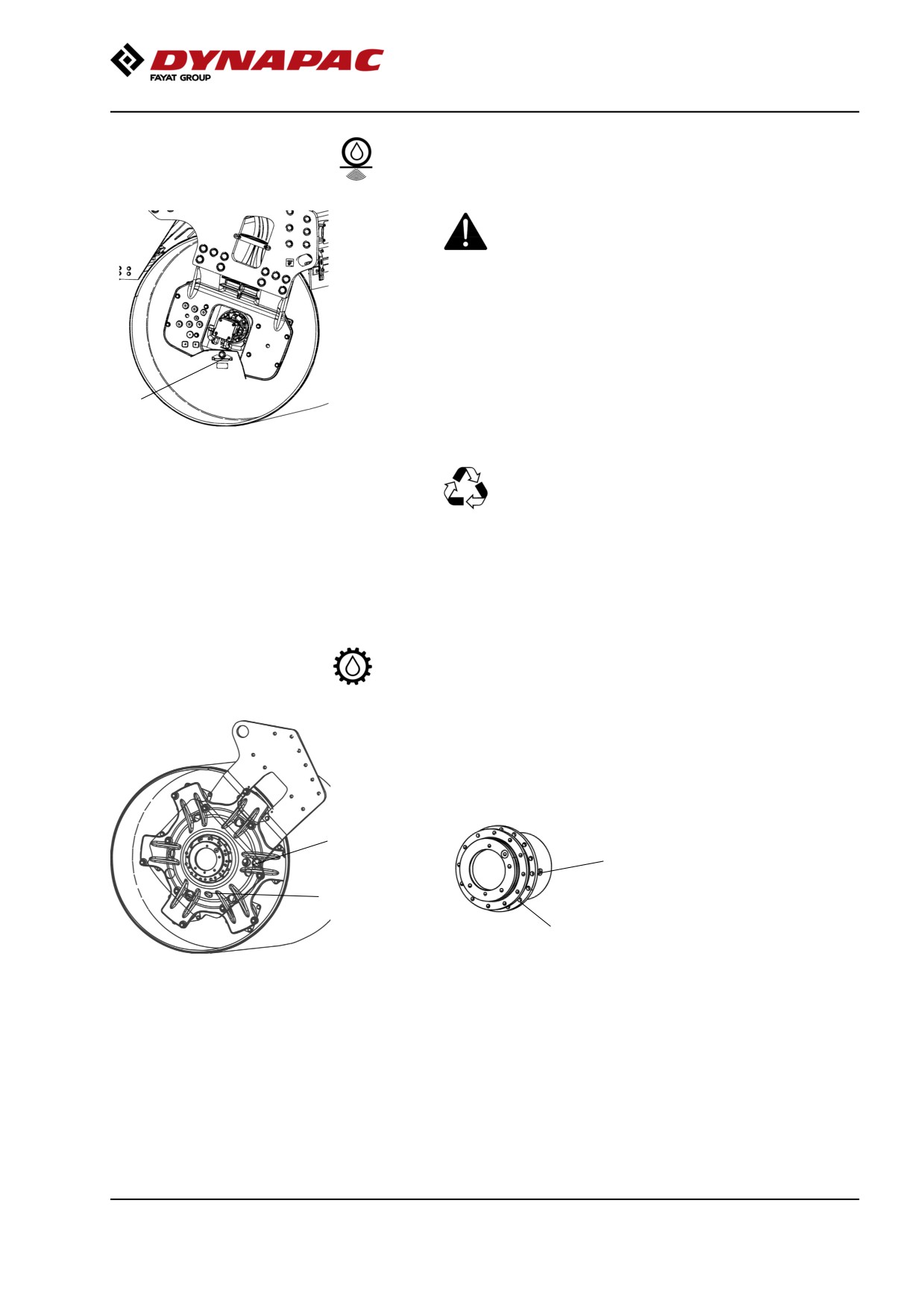
Maintenance - 1000h
Drum - Oil change
Take great care when draining the fluid. Wear
protective gloves and goggles.
Set the roller so that the drain plug (1), the large plug,
is at the lowest position in its rotation.
Place a receptacle that holds at least 20 liters (5.3 gal)
1
under the drain plug.
Remove the drain plug (1). Allow all the oil to drain out
Fig. Drum, vibration side
1. Drain plug
and refit the plug.
Deliver the drain oil to environmentally correct
handling.
See under the heading 'Every 500 hours of operation'
for filling oil.
Drum gear - Oil change
Place the roller on a level surface.
Wipe clean, unscrew the plugs (1, 2) and drain the oil
into a suitable receptacle, capacity about 2 liters (0.5
gal.).
2
2
Fig. Drum gear
1
1
Fig. Drum gear
1. Drain plug
2. Ventilating plug
141
Maintenance - 1000h
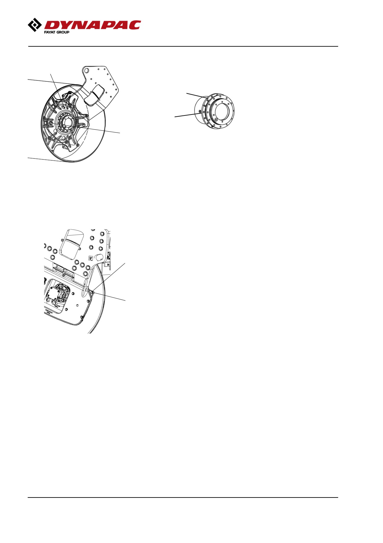
Drum gear - Checking the oil level
2
Move the machine until the inspection/filling holes are
in position for filling.
2
1
Fig. Drum gear
1
Refill with new oil. Use transmission oil according to
Fig. Oil level check - drum gear
the lubricant specification.
1. Level plug
2. Filling plug
Ensure that the oil level reaches up to the lower edge
of the plug hole.
Clean and refit the plugs.
Rubber elements and attachment screws
Check
Check all rubber elements (1). Replace all elements if
25% or more than 25% of the number on one side of
the drum have cracks deeper than 10-15 mm (0.4-0.6
in).
1
Check using a knife blade or pointed object.
Check also that the attachment screws (2) are
tightened.
2
Fig. Drum, vibration side
1. Rubber element
2. Attachment screws
142
Maintenance - 1000h
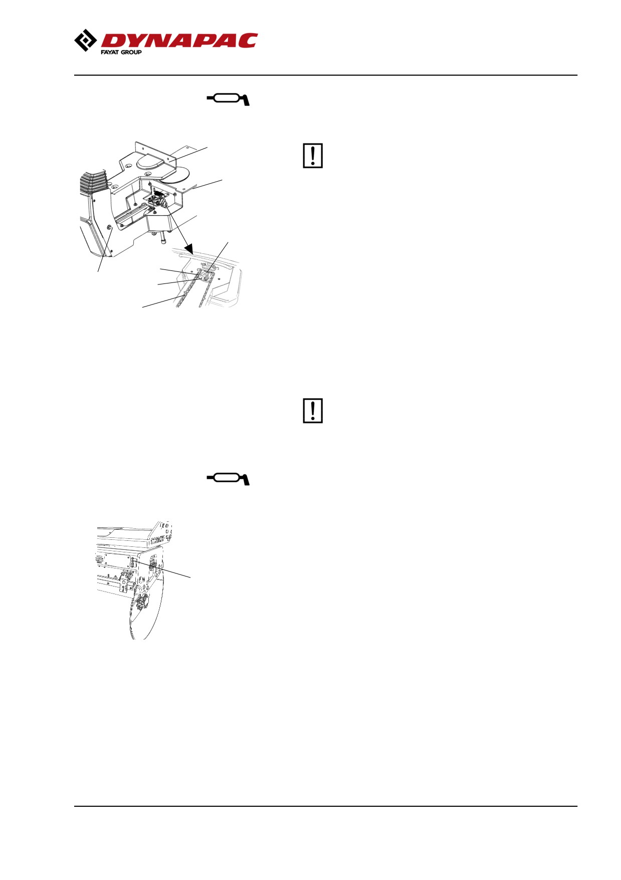
Seat bearing - Lubrication
5
Keep in mind that the chain is a vital part of the
steering mechanism.
6
Remove the cover (5) to access the lubrication nipple
(1). Lubricate the operator seat slew bearing with three
2
strokes of a hand-operated grease gun.
Clean and grease the chain (3) between the seat and
3
the steering column.
4
1
Also grease the seat slide rails (6).
7
If the chain is slack on the sprocket (2), loosen the
Figure. Seat bearing
screws (4) and move the steering column forward.
1. Grease nipple
Tighten the screws and check chain tension.
2. Gearwheel
3. Steering chain
No not tension the chain too tightly. It should be
4. Adjusting screw
possible to move the chain about 10 mm (0.4 in) to the
5. Cover
side with a forefinger/thumb at the marking (7) in seat
6. Slide rails
7. Marking
frame. Fit the chain lock at the bottom.
If the seat starts to be stiff when adjusting, it
should be lubricated more often than specified
here.
Pivot bearing (Optional) - Lubrication
Grease each nipple (1) with five strokes of a
hand-operated grease gun.
Use grease as specified in the lubricant specification.
1
Fig. Rear drum
1. Grease nipples x 4
143
Maintenance - 1000h
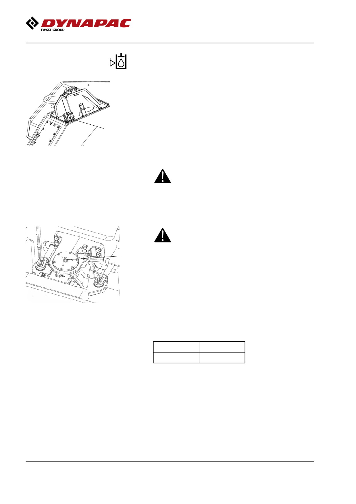
Hydraulic reservoir cap - Check
Turn up the machine so that the tank cap is accessible
from the left side of the machine.
Unscrew and make sure that the reservoir cap is not
clogged. Air must have unobstructed passage through
the cap in both directions.
1
If passage in either direction is blocked, clean the filter
with a little diesel oil and blow through with
Figure. Rear frame front left side
compressed air until the block is removed, or replace
1. Hydraulic reservoir cap
the cap with a new one.
Wear protective goggles when working with
compressed air.
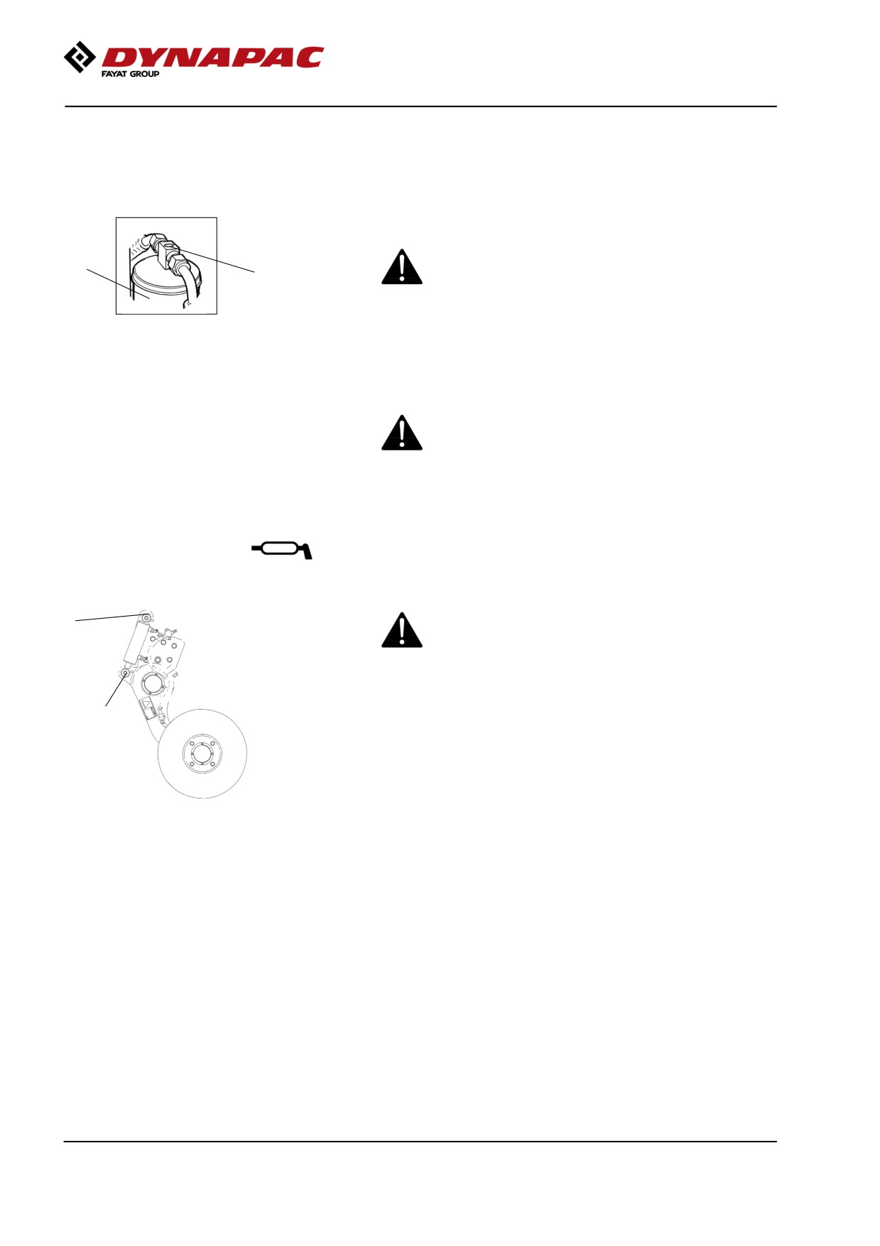
Steering hitch - Tightening
Nobody must be allowed near the steering joint
when the engine is running. Risk of being
crushed when the steering is operated. Switch
off the engine and activate the parking brake
1
before lubricating.
The easiest way to identify if you have this type of
steering hitch is that it has a new type of nut (1) at the
top, as shown.
Fig. Steering hitch
1. Nut
Actual torque (Nm) should be when the machine's
position is straight ahead.
M14
174 Nm
M16
270 Nm
144

Maintenance - 1000h
Cab
Fresh air filter - Replacing
There is one fresh air filter (1), placed on the front of
the cab.
Remove the protective cover.
Undo the screws (2) and remove the complete holder.
Remove the filter insert and replace with a new filter.
2
The filter may need to be changed more often if the
machine is operated in a dusty environment.
2
1
Fig. Cab, front
1. Fresh air filter (x1)
2. Screw (x2)
Air conditioning (Optional)
- Overhaul
Regular inspection and maintenance is necessary to
ensure satisfactory long-term operation.
Clean all dust from the condenser element (1) using
compressed air. Blow from above downwards.
The air jet can damage the element flanges if it is
too powerful.
2
1
Figure. Cab
Wear protective goggles when working with
1. Condensor element
compressed air.
2. Drying filter
Inspect the condenser element attachment.
Check the system hoses for chafing. Make sure that
drainage from the cooling unit is unobstructed so that
condensation does not accumulate inside the unit.
145
Maintenance - 1000h
Air conditioning (Optional)
Drying filter - Inspection
With the unit in operation, check using the sight glass
(1) that bubbles are not visible on the drying filter.
Park the roller on a level surface, chock the wheels
2
and activate the parking brake.
1
Figure. Drying filter
The filter is placed at the top of the rear part of the cab
1. Sight glass
2. Filter holder
roof.
If bubbles are visible through the sight glass, this
indicates that the refrigerant level is too low. Stop the
unit to avoid risking damage. Fill up with refrigerant.
The refrigerant circuit is only to be worked on by
authorized companies.
Edge cutter (Optional)
- Lubrication
Refer to the operation section for information
2
on how to operate the edge cutter.
1
Grease the two points as shown in the figure.
Grease should always be used for lubrication.
See the lubricant specifications.
Grease all bearing points with five strokes
Fig. Two grease points for lubricating
of a hand-operated grease gun.
the edge cutter
146
Maintenance - 2000h
Maintenance - 2000h
Performed after 2000 operating hours
(every two years)
Park the roller on a level surface.
The engine must be switched off and the
parking brake activated when checking or
adjusting the roller, unless otherwise specified.
Ensure that there is good ventilation (air
extraction) if the engine is run indoors.
Risk of carbon monoxide poisoning.
Diesel engine
Oil change
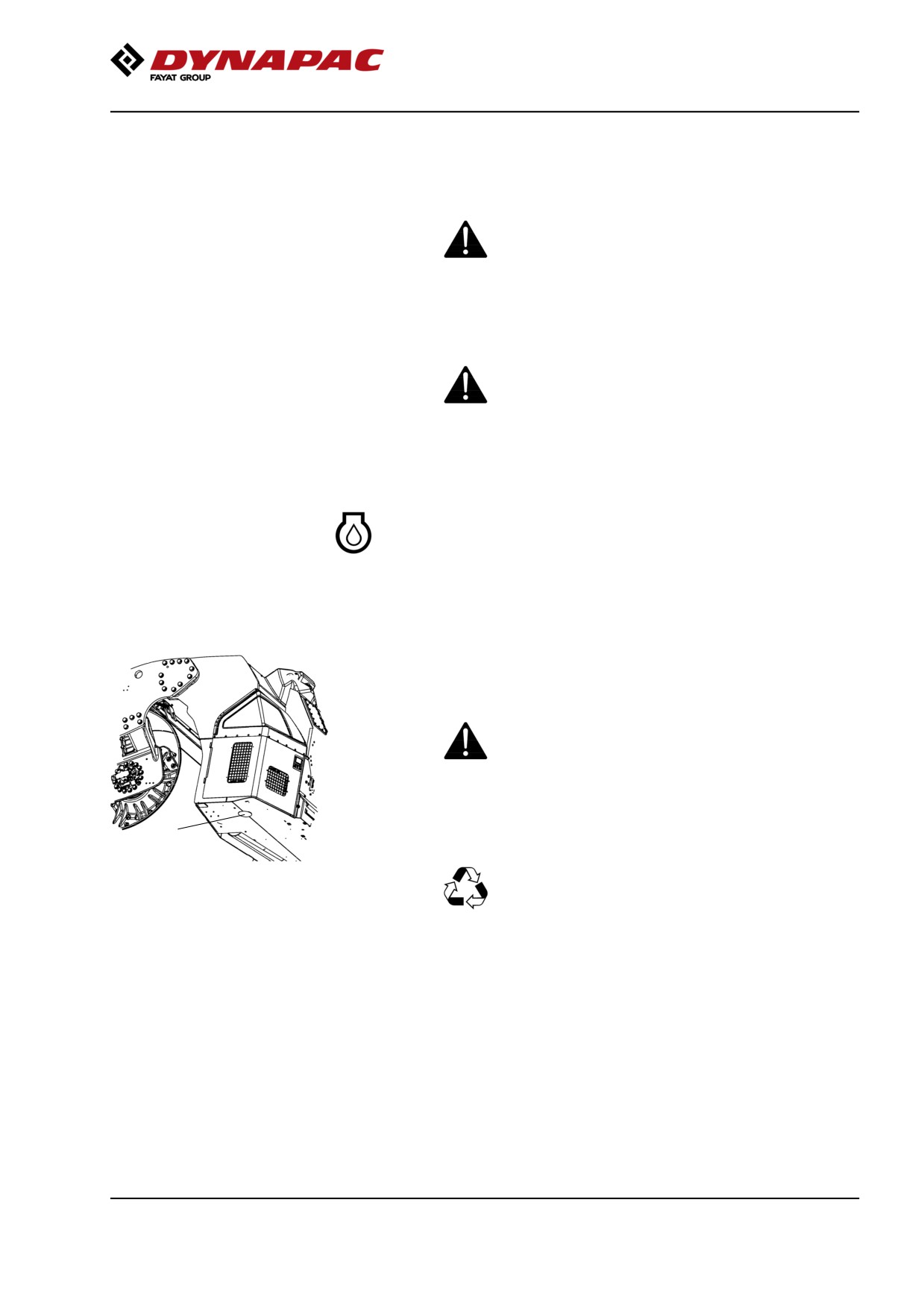
The engine's oil drain plug is located under the rear
frame on the machine on the right side.The drain plug
is accessed by first removing the rubber plug on the
underside of the frame.
Drain the oil when the engine is warm. Place a
receptacle that holds at least 14 liters (15 qts) under
the drain plugs.
Take great care when draining engine oil. Wear
protective gloves and goggles.
1
Unscrew the drain plug (1). Allow all the oil to drain out
and refit the plug.
Deliver the drain oil for environmentally correct
Figure. Underside of rear frame
handling.
1. Oil draining of diesel engine
Fill with fresh engine oil, see Lubricant specification or
the engine manual for the correct grade of oil.
Fill with the requisite volume of engine oil. See
technical specifications before starting the machine.
Allow the engine to idle for a few minutes, and then
switch off the engine.
Check the dipstick to ensure that the engine oil level is
correct. Refer to the engine manual for details. Top up
with oil if necessary to the max mark on the dipstick.
147
Maintenance - 2000h
Engine
Replacing oil filter
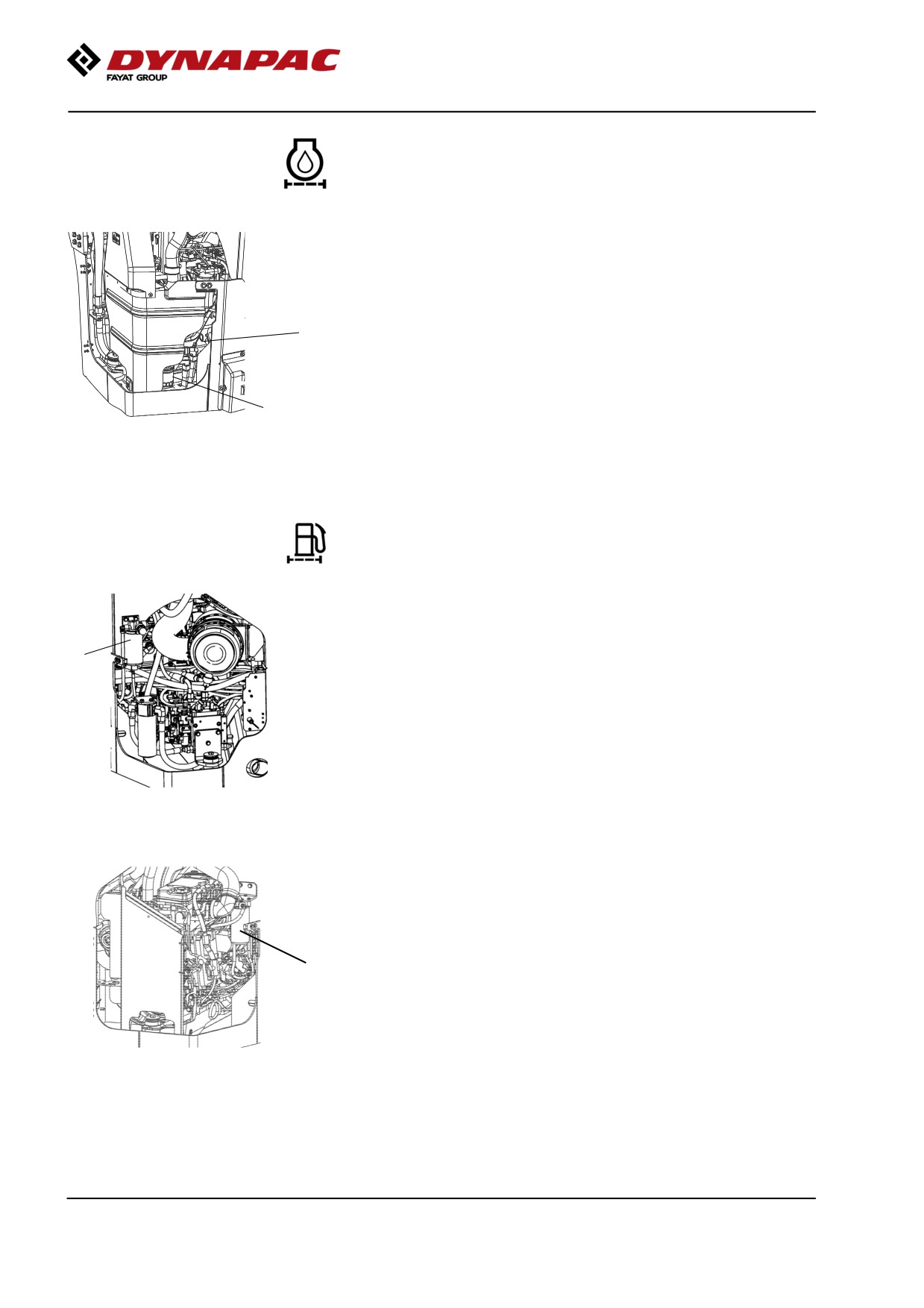
Check the dipstick (2) to ensure that the engine oil
level is correct. Refer to the engine manual for details.
2
The oil filter (1) can be accessed via the right engine
compartment door.
1
See the engine manual for information about replacing
the filter.
Fig. Engine compartment, right side
1. Oil filter
2. Dipstick
The engine fuel filter - replacement/cleaning
The fuel filter is placed on the left side of the engine
compartment.
1
Unscrew the bottom and drain off any water, and then
replace the filter unit.
Figure. Engine compartment, left side
1. Prefilter
Replace the fuel filter, located on the right side of the
engine compartment.
Start the engine and check that the filter is well sealed.
1
Figure. Engine compartment, right
side.
1. Fuel filter
148