DYNAPAC Vibratory roller CC224HF/324HF/384HF, CC2200/3200/3800, CC3800H. Instruction manual (2023) - page 5
Maintenance - 2000h
Hydraulic fluid cooler
Checking - Cleaning
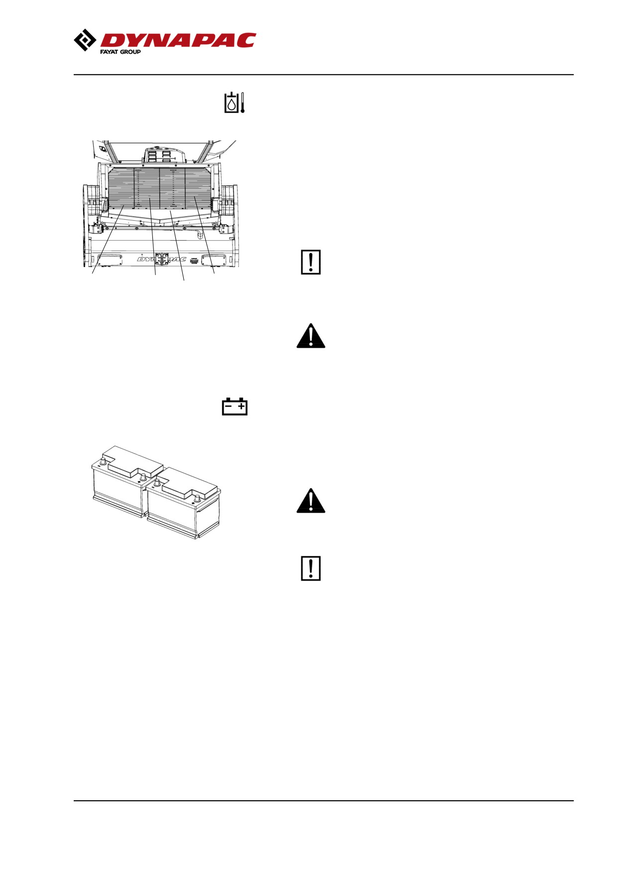
The water and hydraulic fluid coolers are accessible
when the cooler grill (4) is removed.
Make sure that the air flow through the cooler is
unobstructed. Dirty coolers are blown clean with
compressed air or washed clean using a
high-pressure water cleaner.
Take care when using a high-pressure water jet.
Do not hold the nozzle too near the cooler.
3
2
1
4
Figure. Cooler
1. Charge air cooler
2. Water cooler
3. Hydraulic fluid cooler
Wear protective goggles when working with
4. Cooler grill
compressed air or high-pressure water jets.
Battery
- Check condition
The batteries are sealed and maintenance-free.
Make sure there is no open flame in the vicinity
when checking the electrolyte level. Explosive gas
is formed when the alternator charges the battery.
Fig. Batteries
When disconnecting the battery, always
disconnect the negative cable first. When
connecting the battery, always connect the
positive cable first.
The cable shoes should be clean and tightened.
Corroded cable shoes should be cleaned and
greased with acid-proof Vaseline.
Wipe the top of the battery.
149
Maintenance - 2000h
Air cleaner
Checking - Change the main air filter
Change the air cleaner's main filter when the
warning lamp on the display lights when the
diesel engine is operating at full speed.
2
3
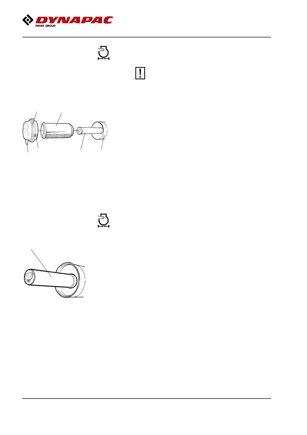
Release the clips (1), pull off the cover (2),
and pull out the main filter (3).
Do not remove the backup filter (4).
Clean the air cleaner if necessary.
See section Air cleaner - Cleaning.
When replacing the main filter (3), insert a new filter
1
4
5
6
and refit the air cleaner in the reverse order.
Fig. Air cleaner
Check the condition of the dust valve (6).
1. Clips
Replace if necessary.
2. Cover
3. Main filter
4. Backup filter
When refitting the cover, make sure that the dust valve
5. Filter housing
is positioned downwards.
6. Dust valve
Backup filter - Change
1
Change the backup filter with a new filter after every
second replacement of the main filter.
To change the backup filter (1), pull the old filter out of
its holder, insert a new filter and reassemble the air
cleaner in the reverse order.
Clean the air cleaner if necessary, see section Air
cleaner - Cleaning.
Fig. Air filter
1. Backup filter
150
Maintenance - 2000h
Air cleaner
- Cleaning
Wipe clean on both sides of the outlet
pipe.
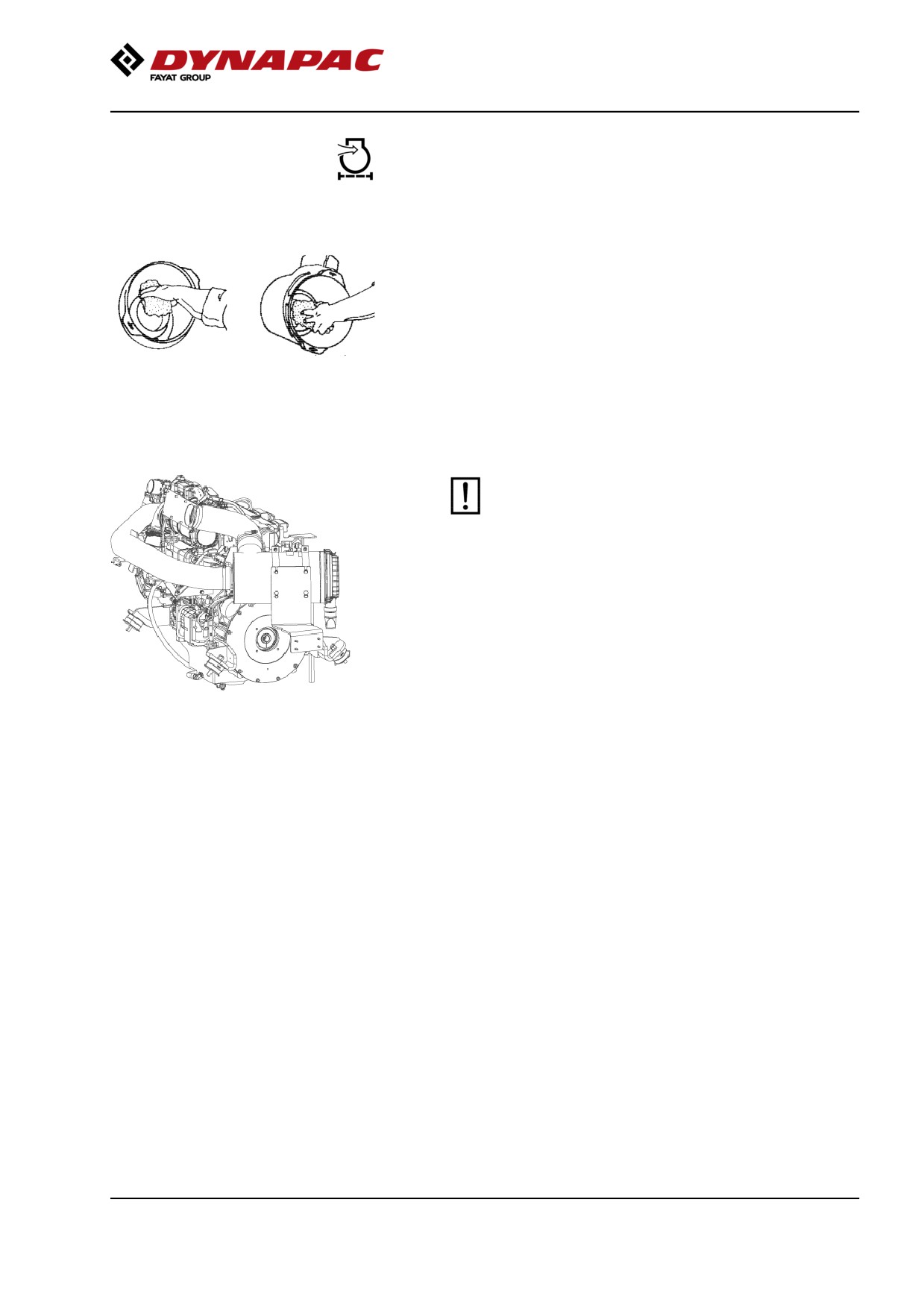
Wipe clean the inside of the cover (2) and the filter
housing (5). See the previous illustration.
Wipe also both surfaces for the outlet pipe; see
adjacent figure.
Inner edge of
Outer edge of outlet
outlet pipe.
pipe.
Check that the hose clamps between the filter
housing and the suction hose are tight and that
the hoses are intact. Inspect the entire hose
system, all the way to the engine.
151
Maintenance - 2000h
Hydraulic filter
Change
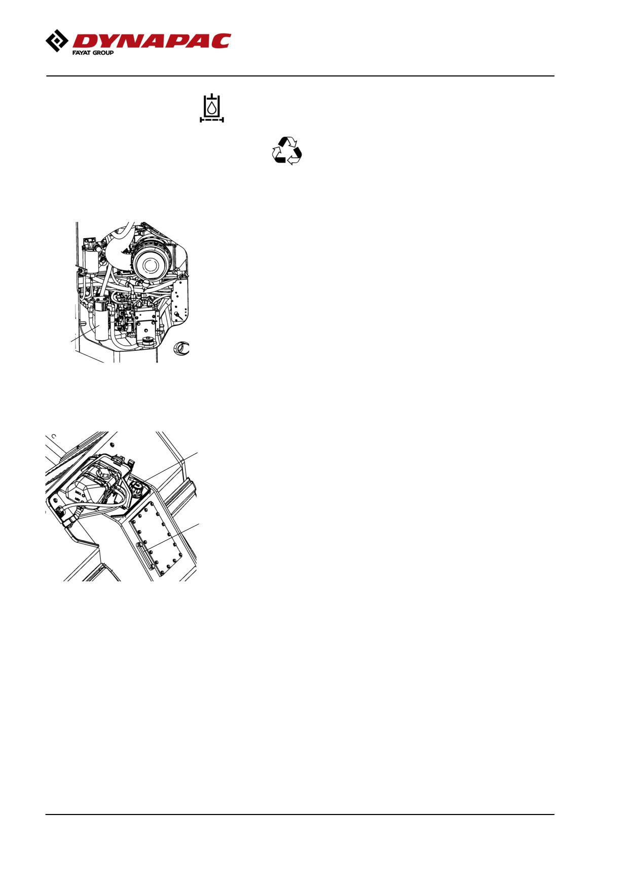
Remove the filter (1) and deliver to special waste
handling. This is a single-use filter and cannot be
cleaned.
Thoroughly clean the filter holder sealing surface.
Apply a thin coat of fresh hydraulic fluid to the rubber
gasket on the new filter.
Screw the filter on by hand, firstly until the filter gasket
makes contact with the filter base. Then rotate a
further ½ turn.
1
Figure. Engine compartment, left
1. Hydraulic fluid filter
Check the hydraulic fluid level in the sight glass (3)
2
and top off as required. See under the heading 'Every
10 hours of operation' for more information.
Start the engine and check that the filter does not leak.
3
Figure. Hydraulic tank
2. Hydraulic reservoir cap
3. Sight glass
152
Maintenance - 2000h
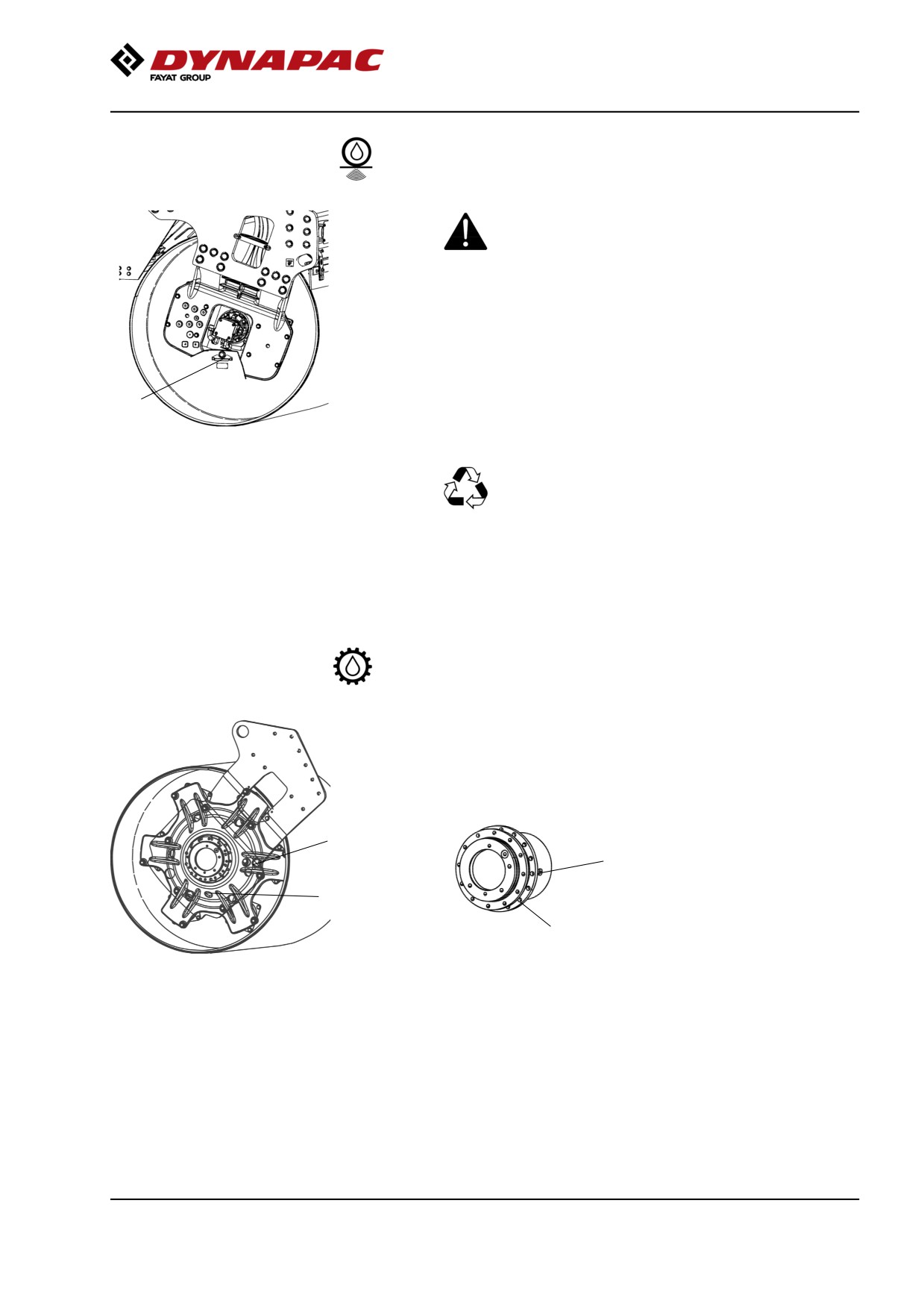
Drum - Oil change
Take great care when draining the fluid. Wear
protective gloves and goggles.
Set the roller so that the drain plug (1), the large plug,
is at the lowest position in its rotation.
Place a receptacle that holds at least 20 liters (5.3 gal)
1
under the drain plug.
Remove the drain plug (1). Allow all the oil to drain out
Fig. Drum, vibration side
1. Drain plug
and refit the plug.
Deliver the drain oil to environmentally correct
handling.
See under the heading 'Every 500 hours of operation'
for filling oil.
Drum gear - Oil change
Place the roller on a level surface.
Wipe clean, unscrew the plugs (1, 2) and drain the oil
into a suitable receptacle, capacity about 2 liters (0.5
gal.).
2
2
Fig. Drum gear
1
1
Fig. Drum gear
1. Drain plug
2. Ventilating plug
153

Maintenance - 2000h
Drum gear - Checking the oil level
2
Move the machine until the inspection/filling holes are
in position for filling.
2
1
Fig. Drum gear
1
Refill with new oil. Use transmission oil according to
Fig. Oil level check - drum gear
the lubricant specification.
1. Level plug
2. Filling plug
Ensure that the oil level reaches up to the lower edge
of the plug hole.
Clean and refit the plugs.
Rubber elements and attachment screws
Check
Check all rubber elements (1). Replace all elements if
25% or more than 25% of the number on one side of
the drum have cracks deeper than 10-15 mm (0.4-0.6
in).
1
Check using a knife blade or pointed object.
Check also that the attachment screws (2) are
tightened.
2
Fig. Drum, vibration side
1. Rubber element
2. Attachment screws
154
Maintenance - 2000h
Seat bearing - Lubrication
5
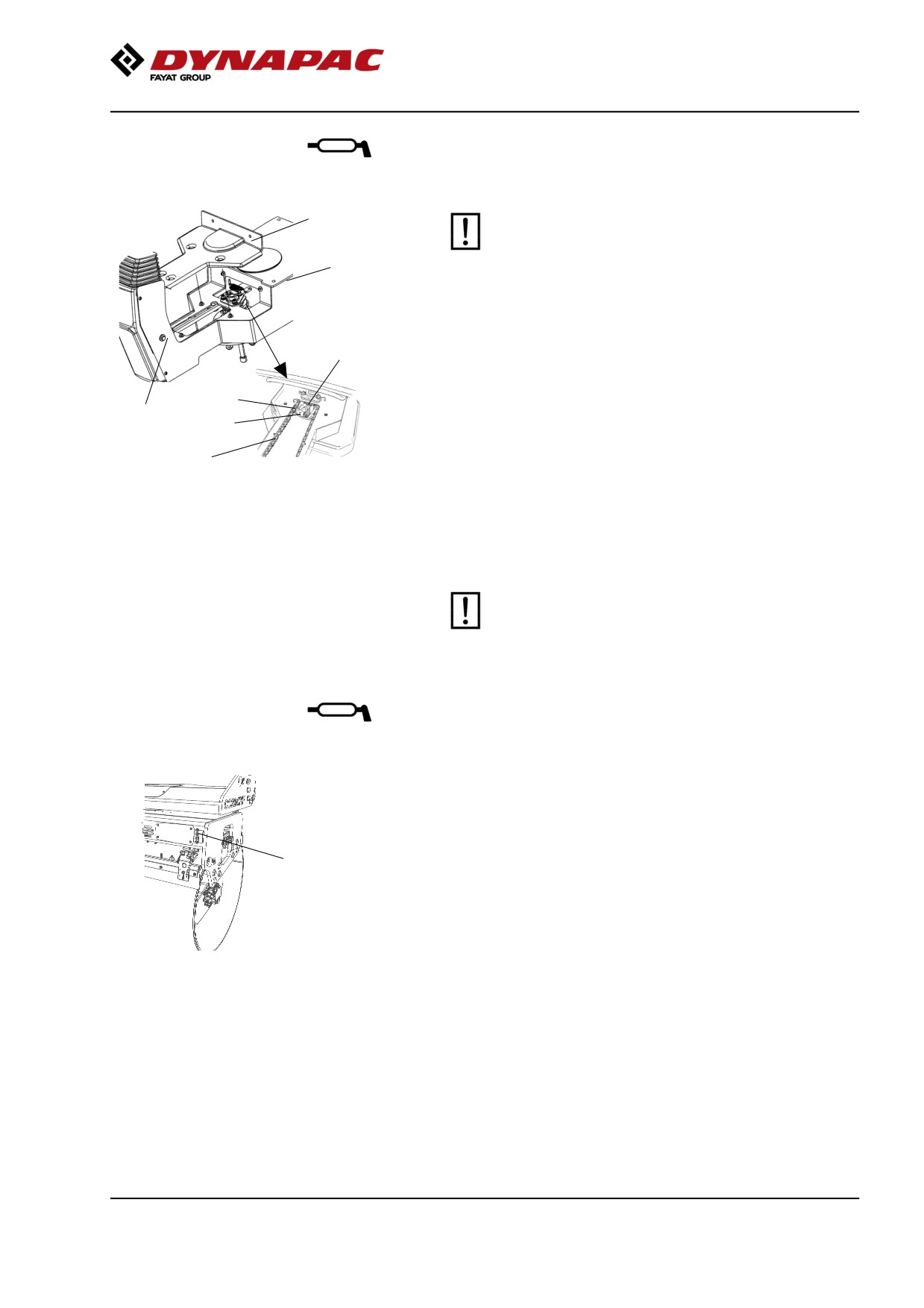
Keep in mind that the chain is a vital part of the
steering mechanism.
6
Remove the cover (5) to access the lubrication nipple
(1). Lubricate the operator seat slew bearing with three
2
strokes of a hand-operated grease gun.
Clean and grease the chain (3) between the seat and
3
the steering column.
4
1
Also grease the seat slide rails (6).
7
If the chain is slack on the sprocket (2), loosen the
Figure. Seat bearing
screws (4) and move the steering column forward.
1. Grease nipple
Tighten the screws and check chain tension.
2. Gearwheel
3. Steering chain
No not tension the chain too tightly. It should be
4. Adjusting screw
possible to move the chain about 10 mm (0.4 in) to the
5. Cover
side with a forefinger/thumb at the marking (7) in seat
6. Slide rails
7. Marking
frame. Fit the chain lock at the bottom.
If the seat starts to be stiff when adjusting, it
should be lubricated more often than specified
here.
Pivot bearing (Optional) - Lubrication
Grease each nipple (1) with five strokes of a
hand-operated grease gun.
Use grease as specified in the lubricant specification.
1
Fig. Rear drum
1. Grease nipples x 4
155
Maintenance - 2000h
Hydraulic reservoir cap - Check
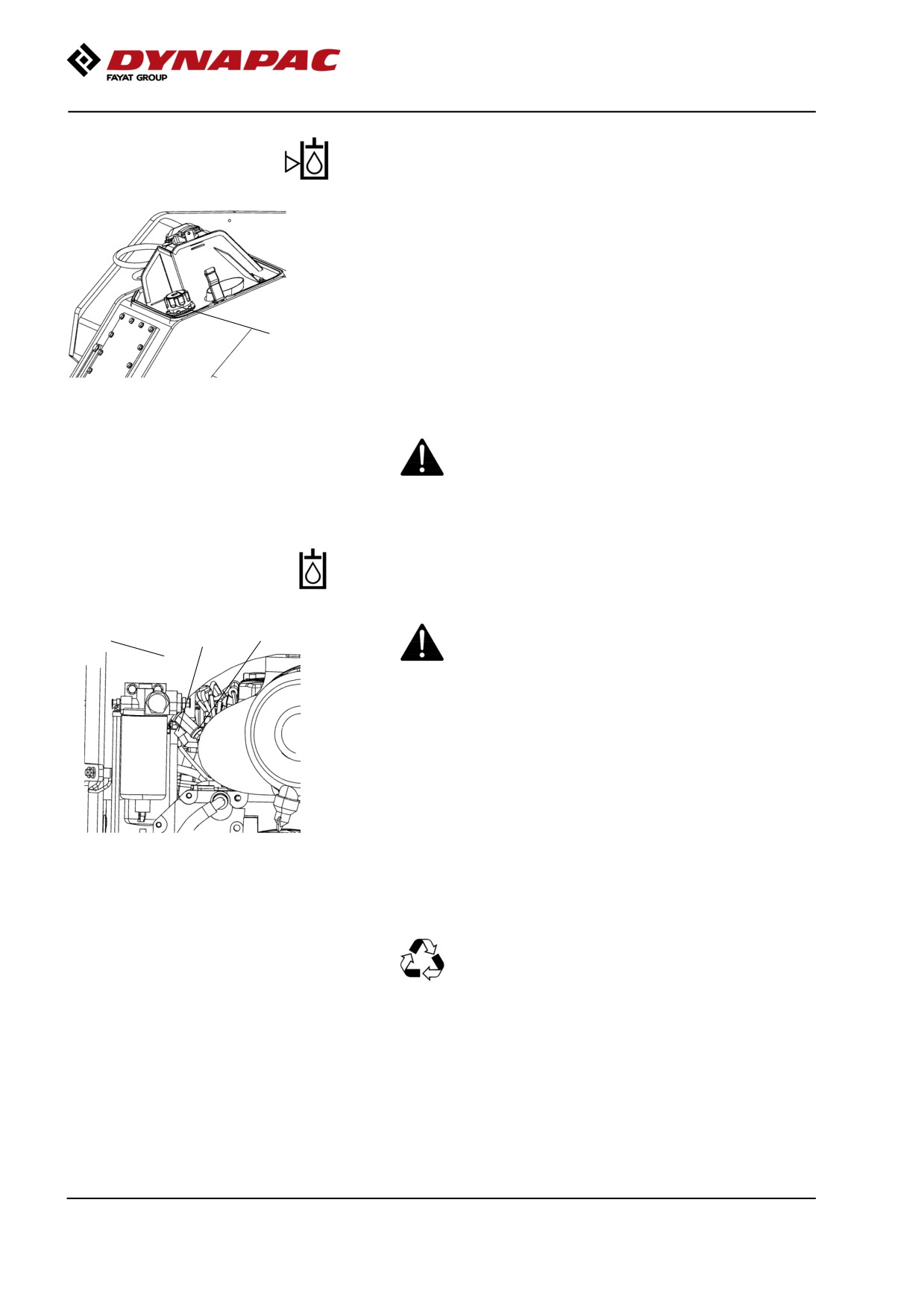
Turn up the machine so that the tank cap is accessible
from the left side of the machine.
Unscrew and make sure that the reservoir cap is not
clogged. Air must have unobstructed passage through
the cap in both directions.
1
If passage in either direction is blocked, clean the filter
with a little diesel oil and blow through with
Figure. Rear frame front left side
compressed air until the block is removed, or replace
1. Hydraulic reservoir cap
the cap with a new one.
Wear protective goggles when working with
compressed air.
Hydraulic reservoir
Fluid change
3
1
Take care when draining the hydraulic fluid. Wear
2
protective gloves and goggles.
Open left engine compartment. The drain plug/valve is
in the area under the hydraulic tank.
Place a receptacle that holds at least 50 liters (13.2
gal) under the engine compartment.
Make sure that the valve (3) is closed.
Figure. Engine compartment under
hydraulic tank (via left side)
Unscrew the oil drain plug (1), and connect a drain
1. Oil drain
hose out from the engine compartment.
2. Hydraulic tank
3. Valve
Open the valve (3) and allow all the oil to run out.
Reset by closing the valve and refitting the plug (1).
Deliver the drained fluid to environmentally
correct handling.
Fill with fresh hydraulic fluid. Refer to the lubricants
specification for grade information.
Replace the hydraulic filter. See section "Maintenance
- 1000 hours".
Start the engine and operate the hydraulic functions.
Check the level in the reservoir and top off as required.
156
Maintenance - 2000h
Fuel tank
- Cleaning
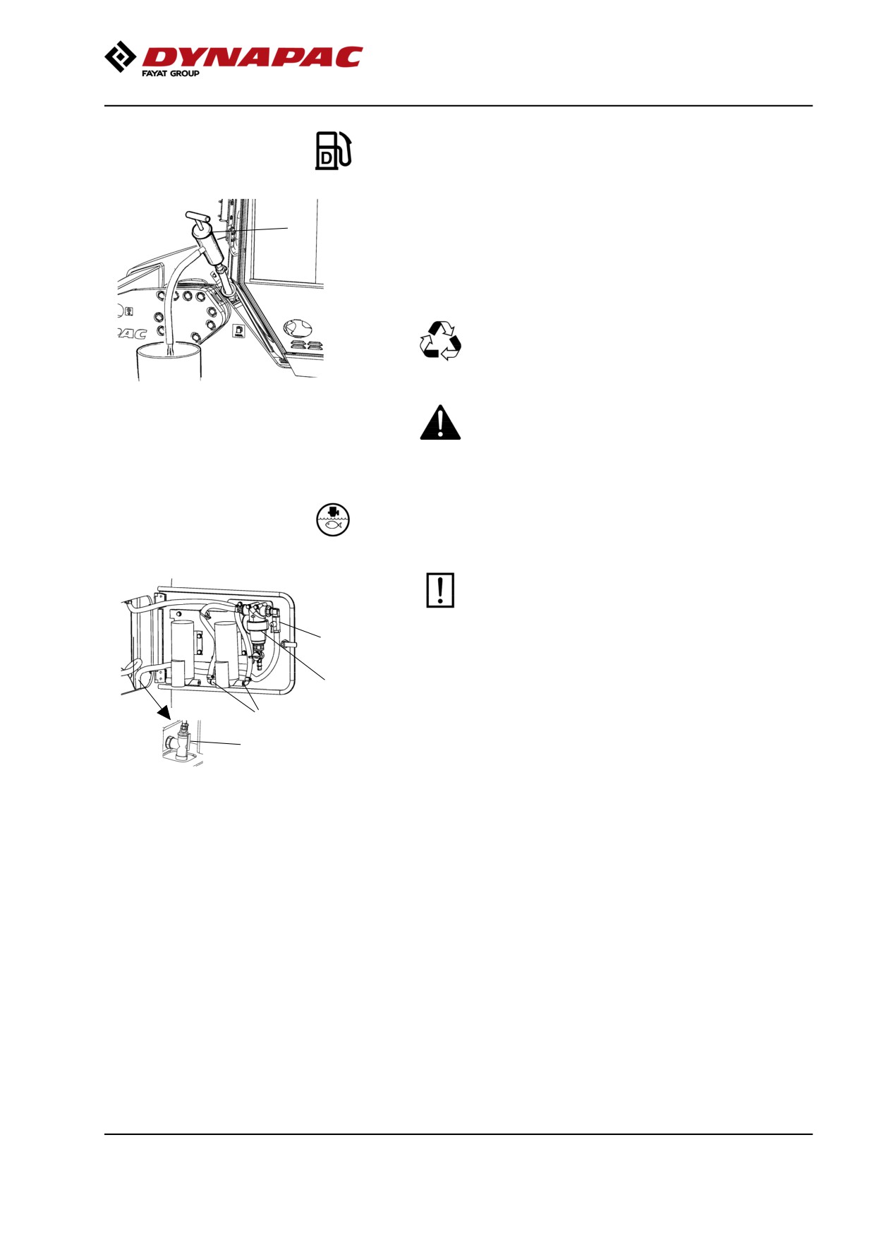
1
It is easiest to clean the tank when it is almost empty.
A drain plug is placed under the left side of the front
frame.
Alternatively drain the tank with a suitable pump, e.g.
an oil drain pump, to bring up any bottom sediment.
Collect the fuel and sediment in a container and
deliver to environmentally correct handling.
Fig. Fuel tank
Keep in mind fire risk when handling fuel.
1. Oil drain pump
Watering system
- Draining
Remember that there is a risk of freezing during
the winter. Empty the tank, pump, filter and lines,
or mix antifreeze in the water.
3
1
There is a drain cock (2) in the space for the pump
system on the central water tank. This can be used to
drain both the tank and parts of the pump system.
4
2
The water hoses are connected to the pump with quick
couplings (4) to simplify draining and where
appropriate replacement to a reserve pump (option).
Figure. Pump system
1. Filter housing
2. Drain cock
3. Stop cock
4. Quick couplings
Newer machines can have sprinkler systems with dual
sprinkler pipes and sprinkler pumps as standard.
The outlet hose from the central tank can be
disconnected and the end placed in a container with
antifreeze to run this through the pump/filter.
157
Maintenance - 2000h
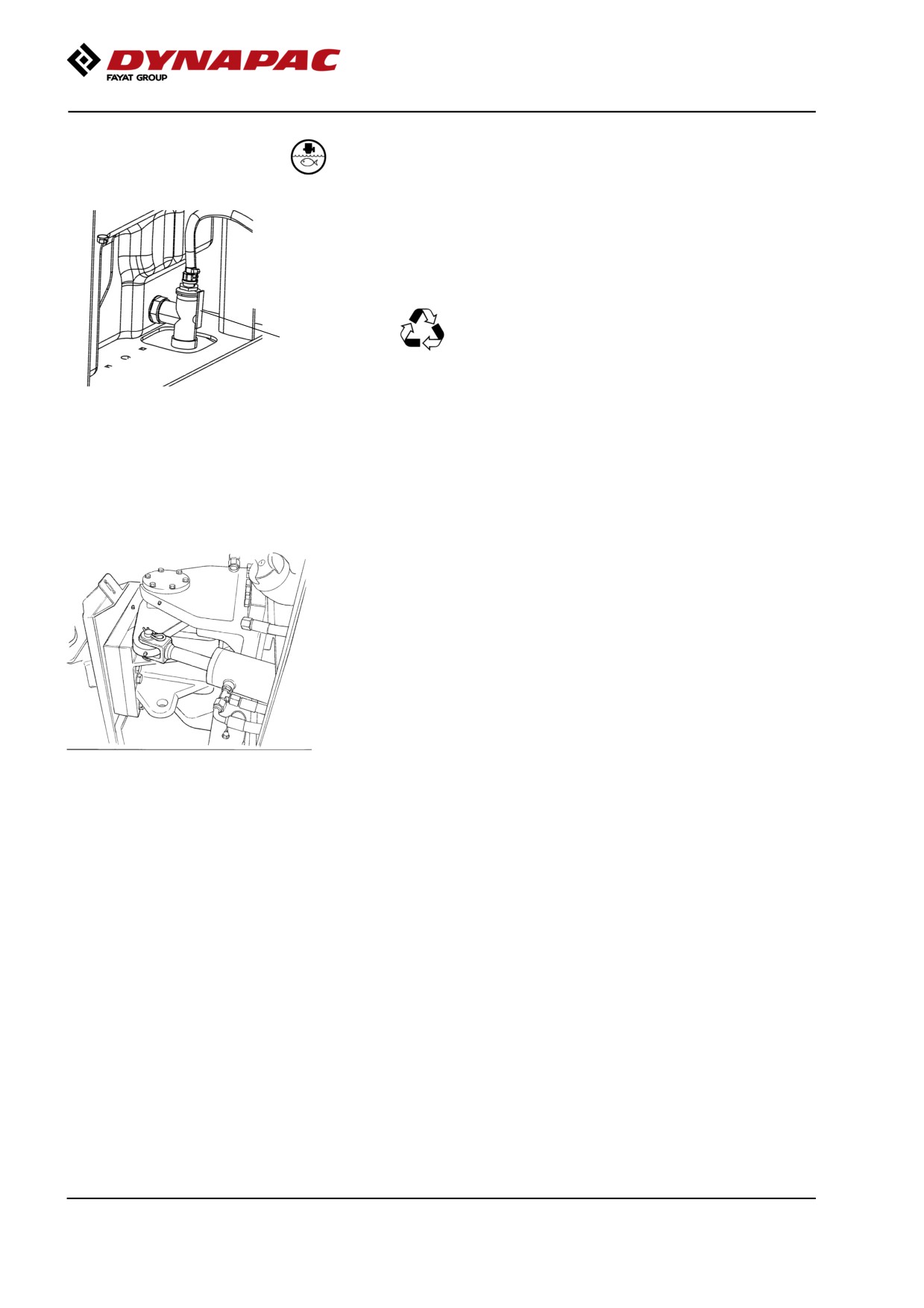
Water tank - Cleaning
Clean the tank/tanks with water and a suitable
detergent for plastic surfaces.
Close the drain cock (2), fill with water and check for
leaks.
The water tanks are made of plastic
(polyethylene) and are recyclable.
2
Figure. Water tank
2. Drain plug
Steering joint - Check
Inspect the steering joint to detect any damage or
cracks.
Check and tighten any loose bolts.
Check also for any stiffness or play in the steering joint.
Fig. Steering joint
158
Maintenance - 2000h
Steering hitch - Tightening
Nobody must be allowed near the steering joint
when the engine is running. Risk of being
crushed when the steering is operated. Switch
off the engine and activate the parking brake
1
before lubricating.
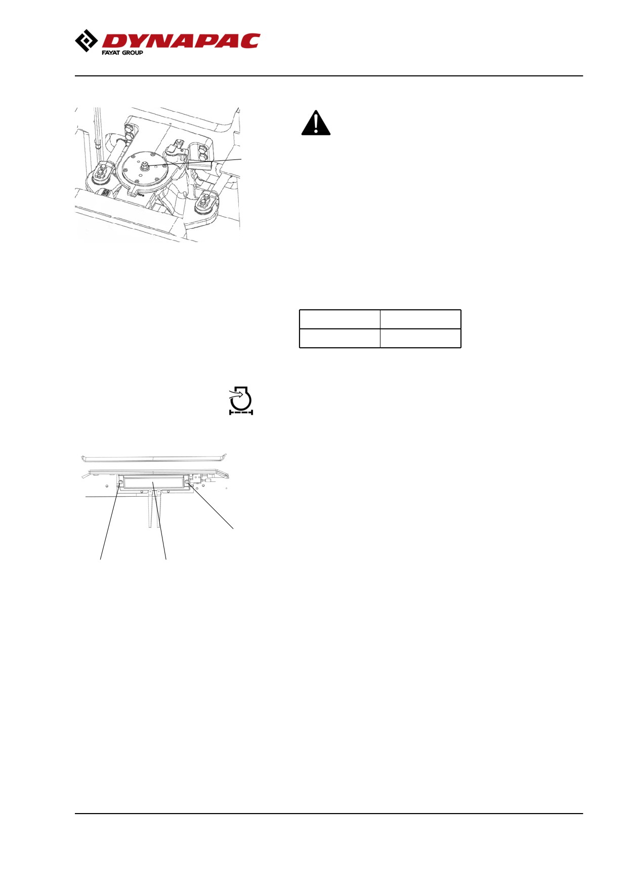
The easiest way to identify if you have this type of
steering hitch is that it has a new type of nut (1) at the
top, as shown.
Fig. Steering hitch
1. Nut
Actual torque (Nm) should be when the machine's
position is straight ahead.
M14
174 Nm
M16
270 Nm
Cab
Fresh air filter - Replacing
There is one fresh air filter (1), placed on the front of
the cab.
Remove the protective cover.
Undo the screws (2) and remove the complete holder.
Remove the filter insert and replace with a new filter.
2
The filter may need to be changed more often if the
machine is operated in a dusty environment.
2
1
Fig. Cab, front
1. Fresh air filter (x1)
2. Screw (x2)
159
Maintenance - 2000h
Air conditioning (Optional)
- Overhaul
Regular inspection and maintenance is necessary to
ensure satisfactory long-term operation.
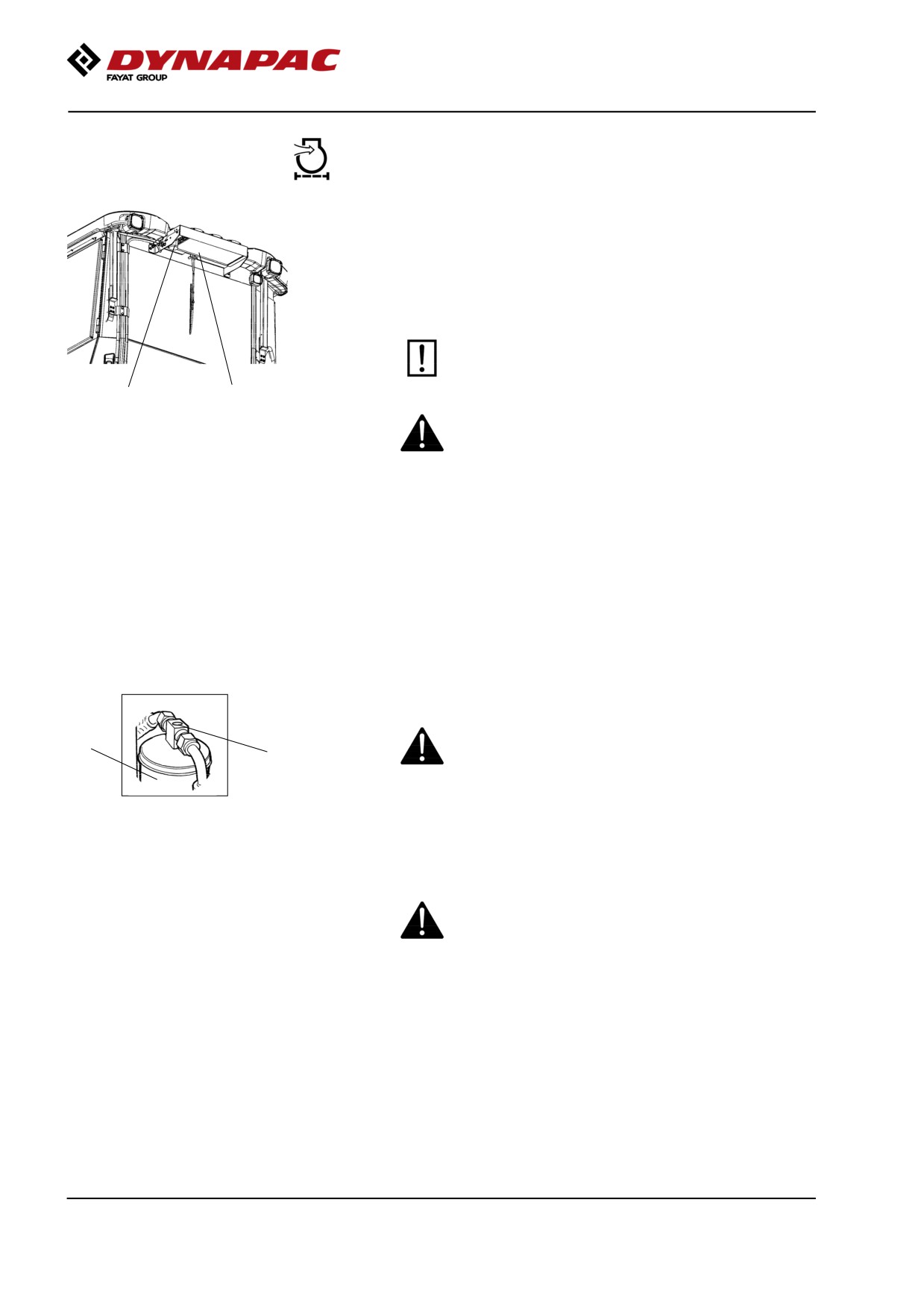
Clean all dust from the condenser element (1) using
compressed air. Blow from above downwards.
The air jet can damage the element flanges if it is
too powerful.
2
1
Figure. Cab
Wear protective goggles when working with
1. Condensor element
compressed air.
2. Drying filter
Inspect the condenser element attachment.
Check the system hoses for chafing. Make sure that
drainage from the cooling unit is unobstructed so that
condensation does not accumulate inside the unit.
Air conditioning (Optional)
Drying filter - Inspection
With the unit in operation, check using the sight glass
(1) that bubbles are not visible on the drying filter.
Park the roller on a level surface, chock the wheels
2
and activate the parking brake.
1
Figure. Drying filter
The filter is placed at the top of the rear part of the cab
1. Sight glass
2. Filter holder
roof.
If bubbles are visible through the sight glass, this
indicates that the refrigerant level is too low. Stop the
unit to avoid risking damage. Fill up with refrigerant.
The refrigerant circuit is only to be worked on by
authorized companies.
160
Maintenance - 2000h
Edge cutter (Optional)
- Lubrication
Refer to the operation section for information
2
on how to operate the edge cutter.
1
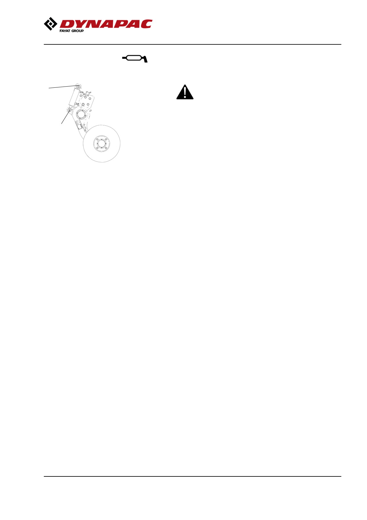
Grease the two points as shown in the figure.
Grease should always be used for lubrication.
See the lubricant specifications.
Grease all bearing points with five strokes
Fig. Two grease points for lubricating
of a hand-operated grease gun.
the edge cutter
161