DYNAPAC Vibratory roller CA2500/2800/3500/4000. Instruction manual (2019) - page 3
Operation
Interlock/Emergency stop/Parking brake -
Check
The interlock, emergency stop and parking brake must
be checked daily before operating. A function check of
the interlock and emergency stop requires a restart.
The interlock function is checked by the operator
standing up from the seat when the roller is moving
very slowly forwards/backwards. (Check in both
directions). Hold the steering wheel firmly and brace
yourself for a sudden stop. A buzzer goes on and after
7 seconds the engine switches off and the brakes are
activated.
Check the function of the emergency stop by pressing
the emergency stop button.
Check the function of the parking brake by activating
the parking brake when the roller is moving very
slowly forwards/backwards. (Check in both
directions). Hold the steering wheel and brace yourself
for a sudden stop when the brakes are activated. The
engine does not switch off.
Vibration
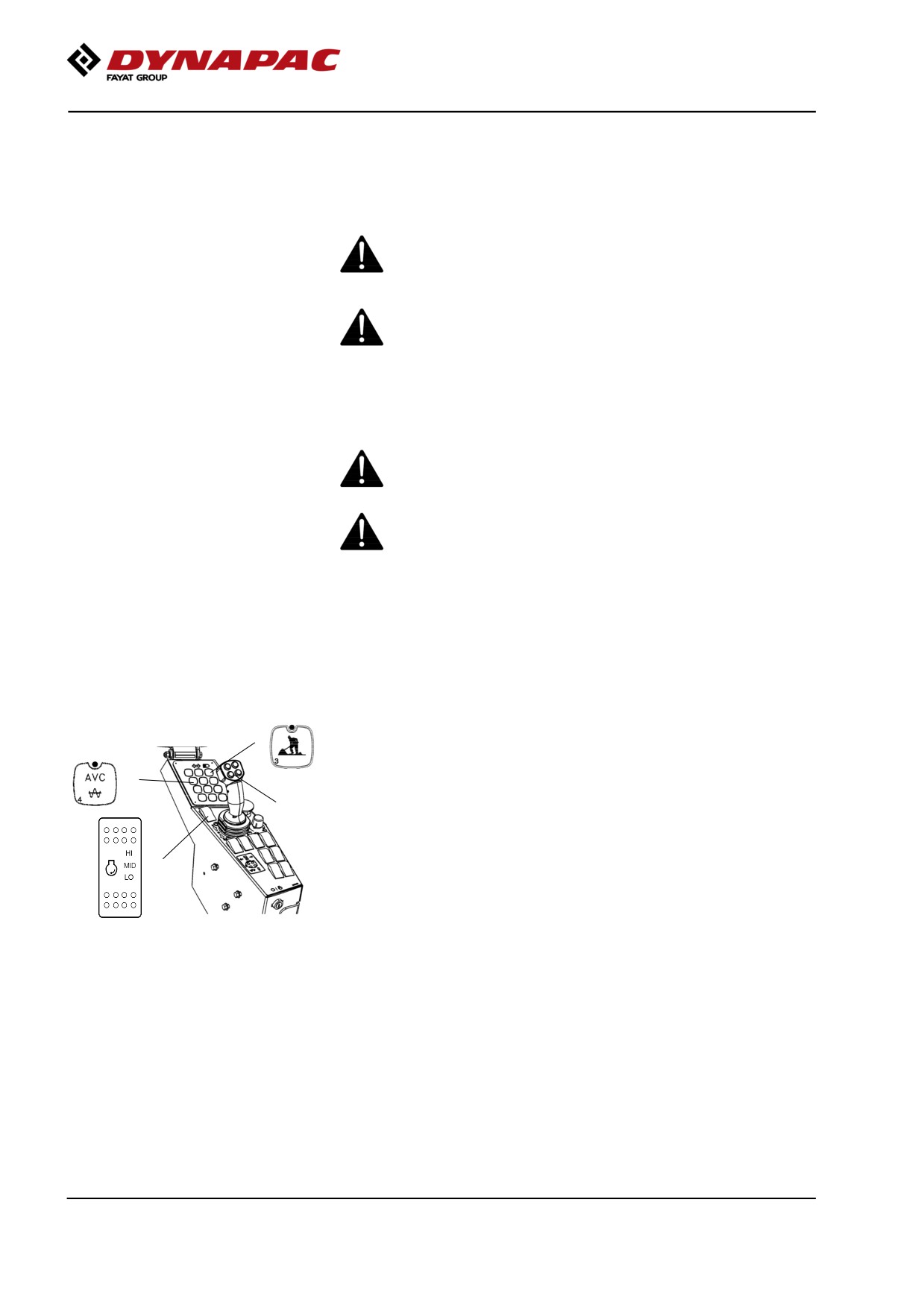
Manual/Automatic vibration
4
Activate the button for the Working mode (4).
Manual or automatic vibration activation/deactivation is
1
selected using button (1).
2
In the manual position, the operator activates vibration
using the switch (2) on the forward/reverse lever.
3
In automatic mode (AVC), vibration is activated when
the speed is ≥ 1.5 km/h (0.9 mph) and turns off at a
speed of 1.2 km/h (0.75 mph)
Activation of vibration for the first time, as well as
Fig. Control panel
disconnection of automatic vibration, are performed
1. Automatic vibration control (AVC)
with the switch (2) on the forward/reverse lever.
2. Switch, vibration On/Off
3. Rpm switch
4. Working mode
Note that vibration can only be activated when the
working mode (4) is activated, and when the speed
selector (3) for the engine is in high (HI) or Eco
mode (ECO). After 10 seconds in neutral, the
vibration is switched off and the machine drops to
low speed.
2019-11-05
70
Operation
Manual vibration - Switching on
Never activate vibration when the roller is
stationary. This can damage both the surface and
the machine.
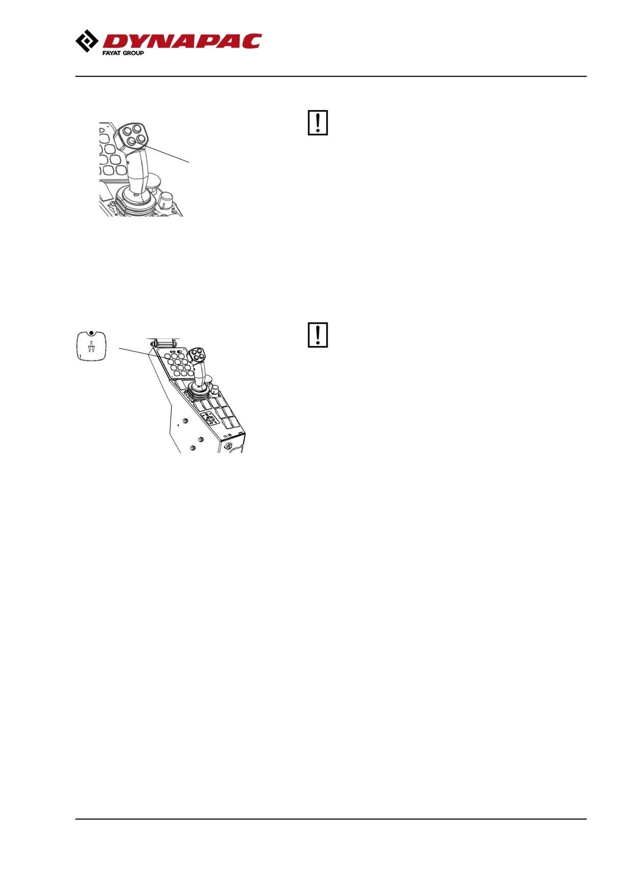
1
Engage and disengage vibration using the switch (1)
on the front of the forward/reverse lever.
Always switch off vibration before the roller comes to a
standstill.
Fig. F/R lever
1. Vibration ON/OFF
Amplitude - Changeover
The amplitude setting must not be change when
vibration is in operation
1
Switch the vibration off and wait until vibration
stops before changing amplitude.
By pressing button (1) high amplitude is achieved.
Fig. Control panel
1. High amplitude
2019-11-05
71
Operation
Seismic - (Optional)
Seismic is the technology that makes the machine and
soil work together.
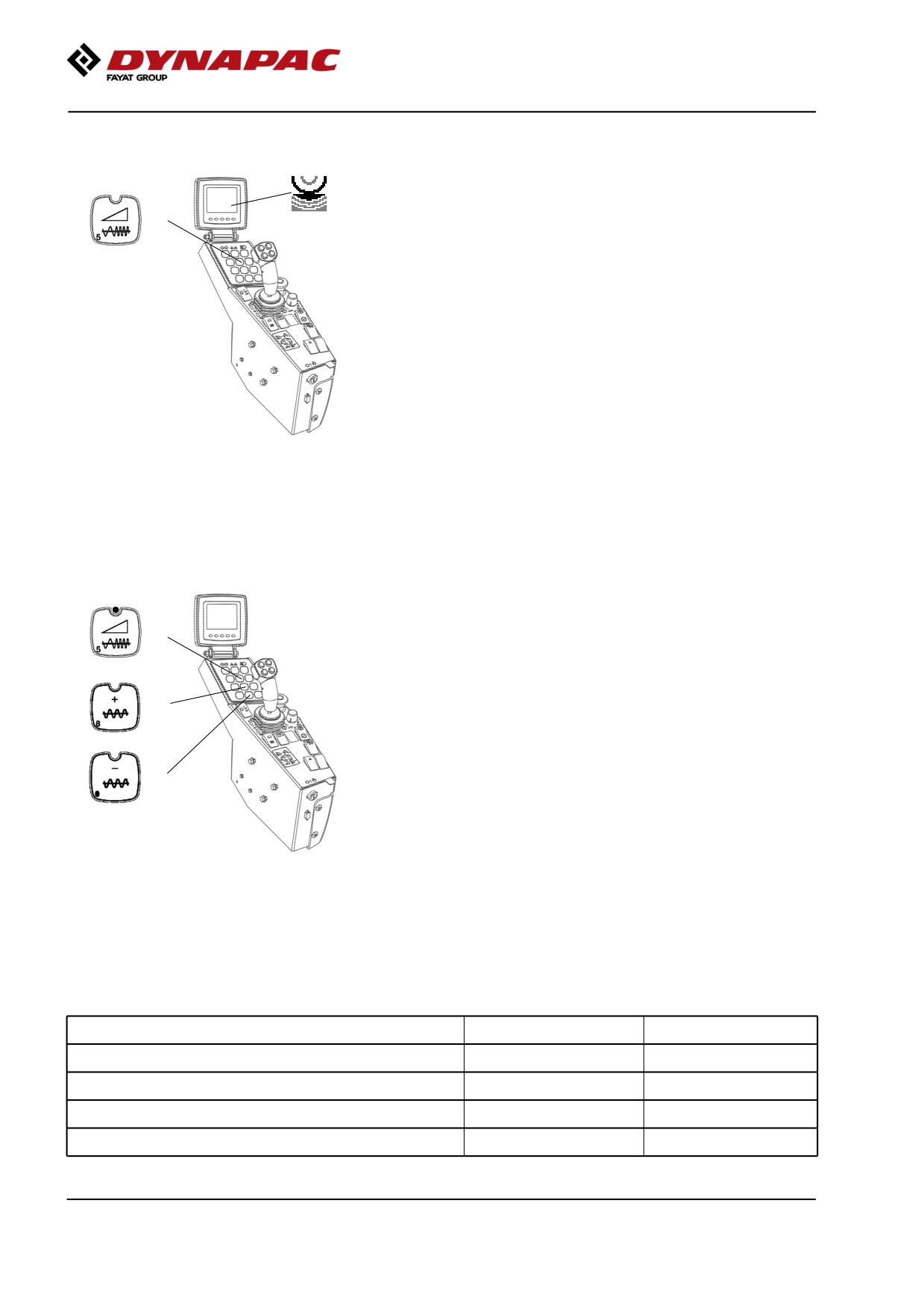
1
Seismic is the innovation that lets the roller determine
the optimum frequency for any compacted material,
monitoring the variations and constantly adjusting to
the changing conditions automatically.
Fig. Function keys
1. Seismic (LED off)
Adjustable (Variable) frequency - (Optional)
Optimum vibration speed depends on the soil type that
is to be compacted and the chosen vibration amplitude.
1
If double jumps occur, reduce the vibration frequency
if possible as an initial measure.
2
If this does not help, select a lower amplitude instead,
if possible.
3
Fig. Function keys
1. Adjustable (Variable) frequency (LED
on)
2. Frequency, increase
3. Frequency, decrease
Soil type(s)
High amplitude
Low amplitude
Fine grade soils (clay and silt)
24 - 26 Hz
28 - 30 Hz
Mixed grade soils (loamy and silty)
24 - 26 Hz
29 - 31 Hz
Coarse grade soils (sand and gravel)
26 - 28 Hz
31 - 33 Hz
Rock fill (crushed rock and rockfill)
24 - 26 Hz
31 - 33 Hz
2019-11-05
72
Operation
Dynapac Compaction Meter (DCM) including
Active Bouncing Control (ABC) - Optional
The Compaction Meter is an accessory used to ensure
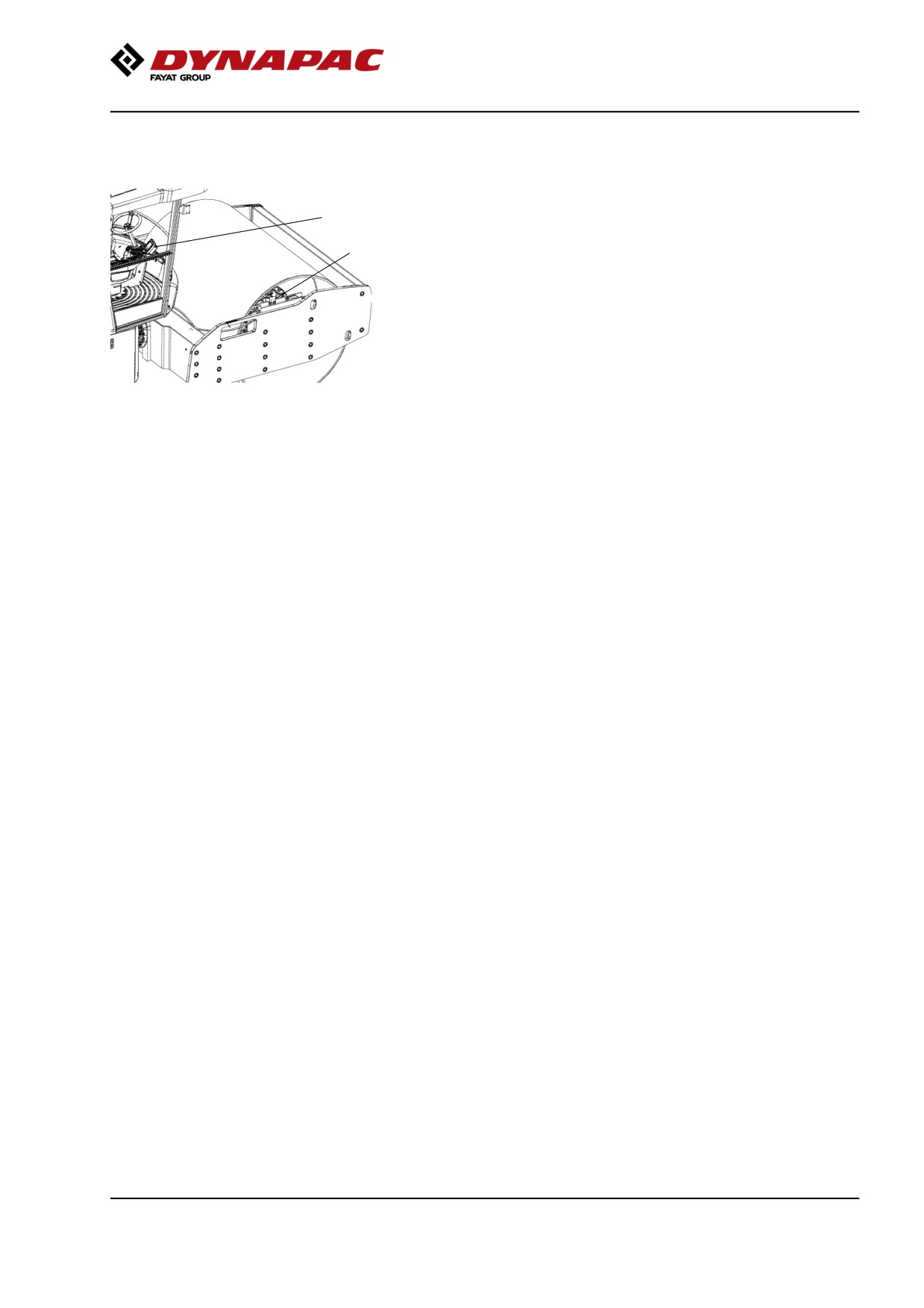
1
the compaction result and enables optimal material
processing. If the Compaction Meter is mounted on
2
the machine, a separate view in the machine display
indicates the stiffness of the surface as a compaction
meter value (CMV, Evib1 or Evib2).
CMV is the value traditionally used on Dynapac rollers.
It is calculated based on a numerical analysis of the
vibration frequency of the drum and the harmonics the
occur as the dynamic stiffness in the compacted
material increases. CMV is a dimensionless, relative.
Evib1 and Evib 2 are calculates based on the drum
Fig. Principal components
contact force on the ground and the deformation that
1. Display with CMV view
occurs in the compacted material. A low contact force
2. Sensor/Processor unit
that causes a big deformation results in a low Evib
value. High force and low deformation consequently
results in a high Evib value. Evib1 is calculated on the
downward movement of the drum (loading phase).
Evib2 is calculated on the upward movement of the
drum (Unloading phase). Which one of the two values
that best correlates to the acceptance control method
must be evaluated from site to site. Different materials
and site conditions result in different correlations.
Evib1 and Evid2 both have the unit Mega-Newton per
square meter (MN/m2).
For more details on the compaction meter
functionality, please refer to the technical specification:
Earthworks - Continuous Compaction Control (CCC)
(CEN/TS 17006:2016) published by CEN, European
Committee for Technical Standardization.
The Active Bouncing Control is always integrated in
the Compaction Meter and after a certain warning time
shuts off vibration if the machine is run in double-jump
(bouncing). This is to save both machine and material
as well as the operator from damages when the
machine starts to double-jump.
The Compaction Meter is available for both D and PD
machines but as the ground contact area varies a lot
on PD the readings may not give any sure
conclusions. However, ABC is still active. The ABC is
only possible to disable via the service tool.
2019-11-05
73
Operation
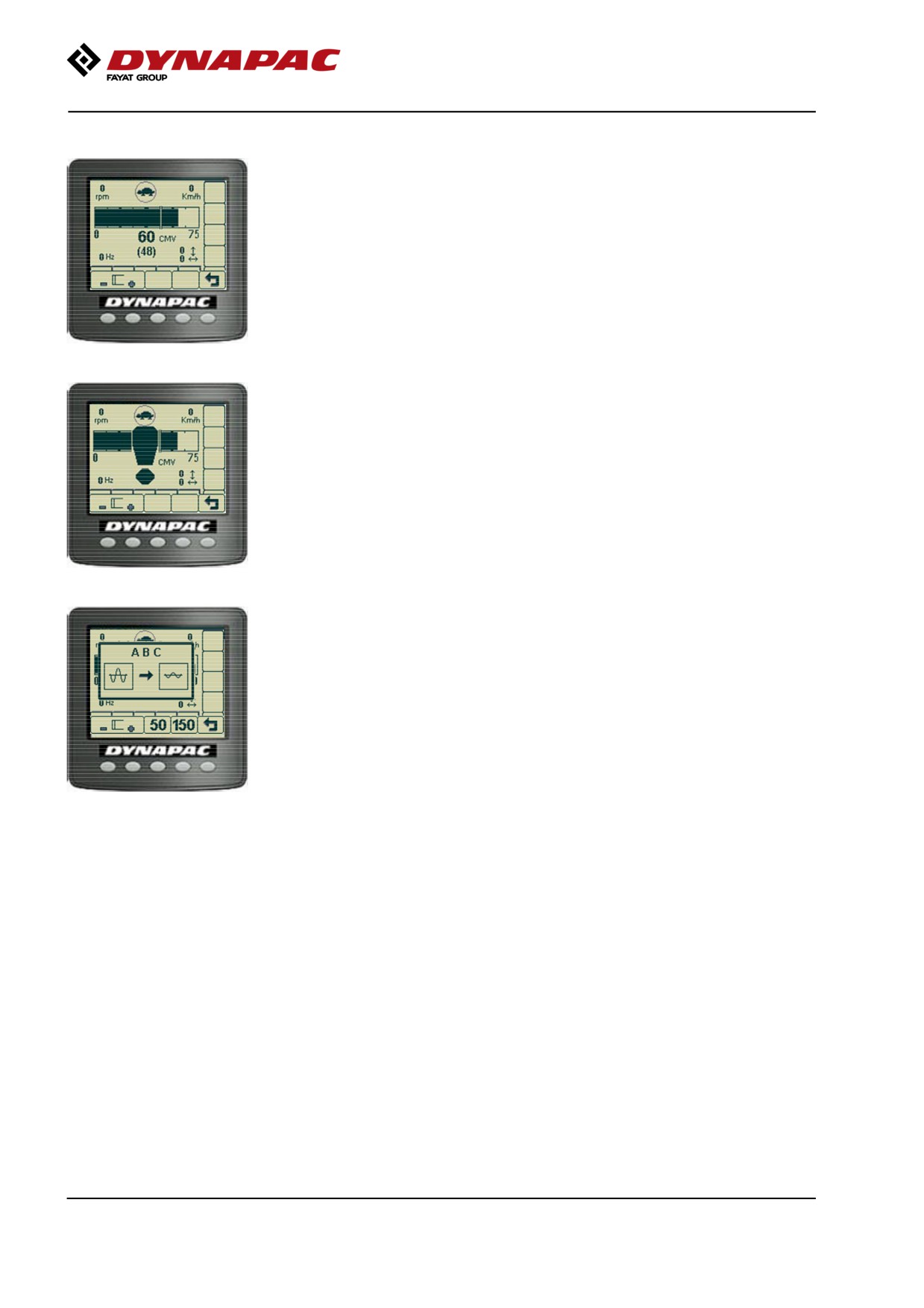
Setting limit
The compaction meter value view in display will give
the operator all information needed during compaction;
engine rpm, gear position, speed, frequency and
inclinations are in display together with actual CMV
and the limit set in brackets. Use the buttons
underneath the display to set the limit. The scale will
switch automatically depending on the CMV reading.
If double-jump occurs the operator will first get a
warning (!).
Secondly the ABC will shut off vibrations and give a
message to the operator to continue compaction with
a lower vibration amplitude setting or if variable
frequency is available reduce the vibration frequency.
The sensor is fitted on the mounting plate of the main
bearing and it senses the vibrating motion of the drum.
The information is transmitted to the processor unit
where it is analyzed.
The analyzed information is presented in the display
as a digital value expressed as CMV, Evib1 or Evib2.
High or low measuring range is automatically selected
and viewed in the display. The resulting numerical
value is a relative measure of the ground stiffness
achieved.
Operation CMV
The Compaction Meter measures the dynamic
stiffness of the ground and presents a value based on
this. The CMV, Evib1 or Evib2 is influenced by the
rolling speed, rolling direction (forward or reverse),
amplitude setting and vibration frequency. The
Dynapac Compaction Meter (DCM) is less sensitive to
small variation in vibration frequency.
The water content in the compacted soil (not relevant
for rock fill) has a large influence on stiffness, wet soil
will result in low values and dry soil will result in higher
values.
When double-jump occurs, the value CMV will be
reduced, these lower values should not be used to
determine if compaction is ready or not.
2019-11-05
74
Operation
NOTE: The operator shall always keep an eye on
where they are driving and not focus too much on the
CMV display, due to safety.
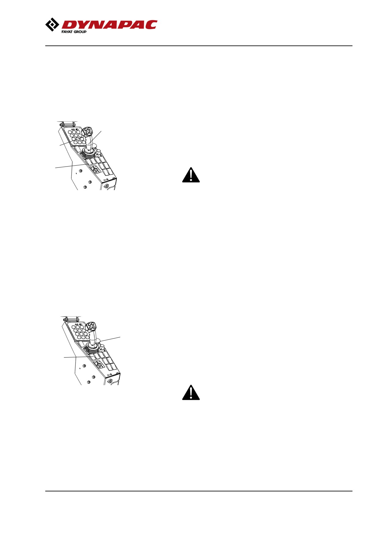
Braking
Normal braking
Press the switch (1) to switch off the vibration.
2
Move the forward/reverse lever (2) to the neutral
position to stop the roller.
1
Always activate the parking brake (3), before leaving
the operator platform.
3
When starting and driving a machine that is cold,
remember that the hydraulic fluid is also cold and
that braking distances can be longer than normal
until the machine reaches the working temperature.
Fig. Control panel
1. Vibration On/Off switch
2. Forward/Reverse lever
3. Parking brake
If the forward/reverse lever is moved quickly (forwards
or backwards) toward/past neutral, the system
switches to a rapid braking Mode and the machine
stops.
Activate normal driving Mode again by moving the
forward/reverse lever back to neutral.
Emergency braking
Braking is normally activated using the
forward/reverse lever. The hydrostatic transmission
1
retards and slows the roller when the lever is moved
towards the neutral position.
2
A disc brake in each drum motor/drum gear and the
rear axle also acts a secondary brake when in motion,
and as a parking brake when stationary. Activated with
the parking brake (2).
For emergency braking, press the emergency stop
Fig. Control panel
(1), hold the steering wheel firmly and be prepared
1. Emergency stop
for a sudden stop. The engine stops.
2. Parking brake
The Diesel engine will stop and must be restarted.
After emergency braking, return the forward/reverse
lever to neutral and deactivate the emergency stop.
2019-11-05
75
Operation
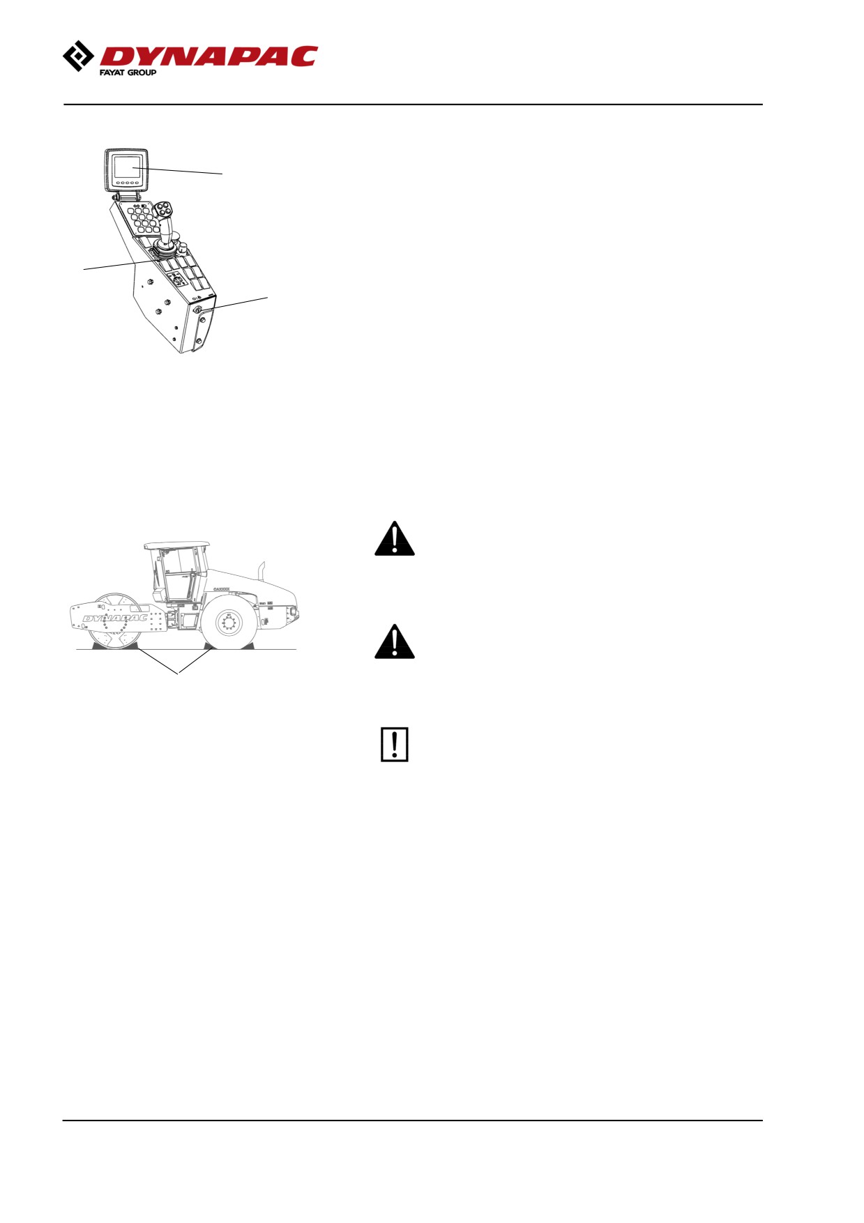
Switching off
Set the speed control in idling position and allow the
1
engine to idle for a few minutes to cool down.
Check the display to see if any faults are indicated.
Switch off all lights and other electrical functions.
Activate the parking brake (3) and then turn the
3
ignition lock (2) to the left to the off position.
2
Fit the instrument cover on the display and top of the
control box (on rollers without cab), and lock it.
Fig. Control panel
1. Display
2. Ignition lock
3. Parking brake
Parking
Chocking the drums
Never disembark from the machine when the is
engine running, unless the parking brake is
activated.
Make sure that the roller is parked in a safe place
with respect to other road users. Chock the drums
if the roller is parked on sloping ground.
1
Fig. Positioning
1. Chocks
Remember the risk of freezing during the winter.
Fill the engine cooling system and the
screenwash bottle in the cab with suitable
anti-freeze mixtures. See also the maintenance
instructions.
2019-11-05
76
Operation
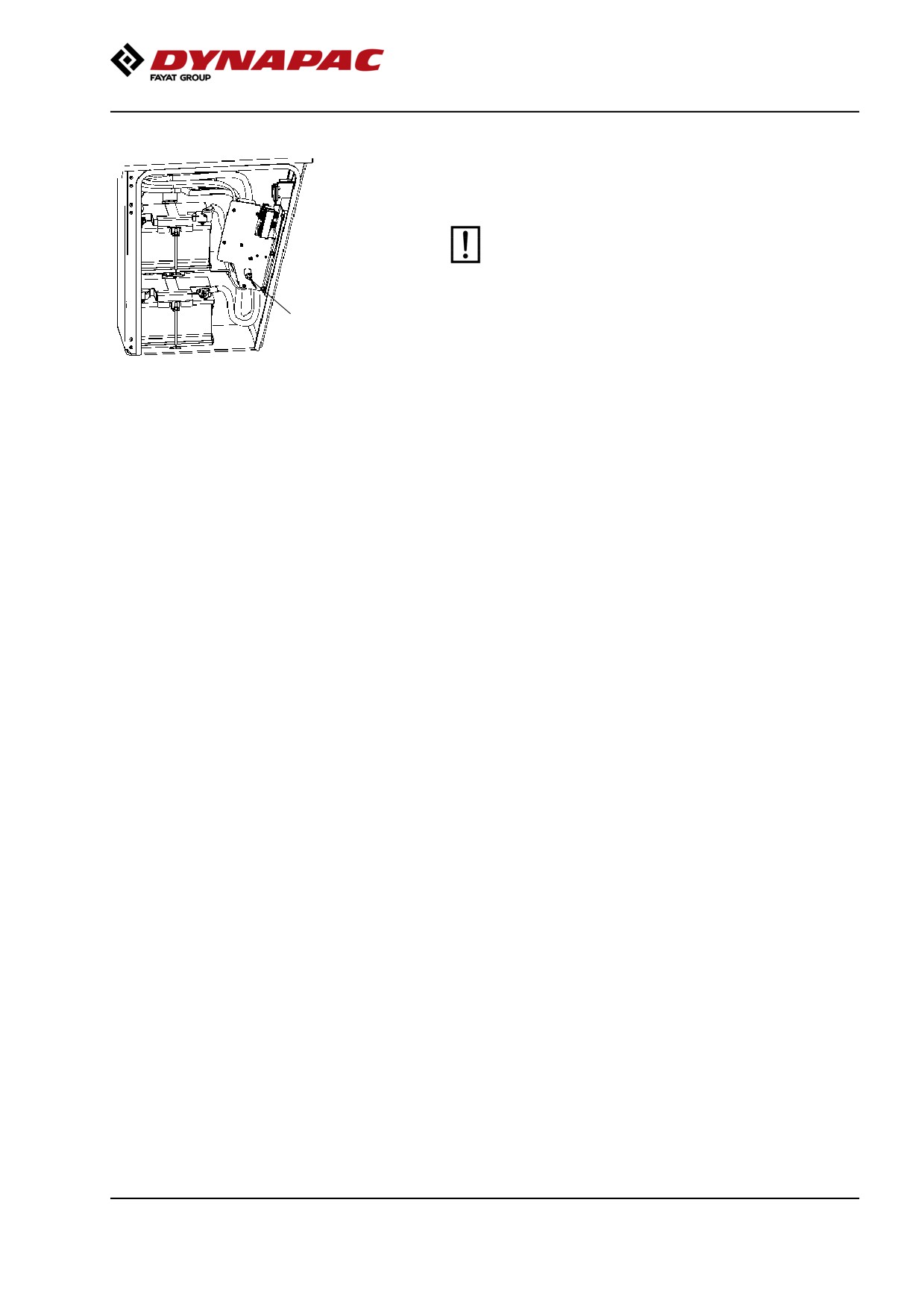
Master switch
Before leaving the roller for the day, switch the master
switch (1) to the disconnected position and remove the
handle.
Before switching off the battery isolation switch,
wait for at least 30 seconds after the ignition lock
has been switched off, in order to avoid the
engine's electronic control unit (ECU) sustaining
damage.
1
This will prevent battery discharging and will also
Fig. Cover, left side
make it difficult for unauthorized persons to start and
1. Master switch
operate the machine. Also lock the hood to the engine
compartment.
2019-11-05
77
Operation
2019-11-05
78
Long-term parking
Long-term parking
The following instructions should be followed
when long term parking (more than one month).
These measures apply when parking for a period of up
to 6 months.
Before re-commissioning the roller, the points marked
with an asterisk * must be returned to the pre-storage
state.
Wash the machine and touch up the paint finish to
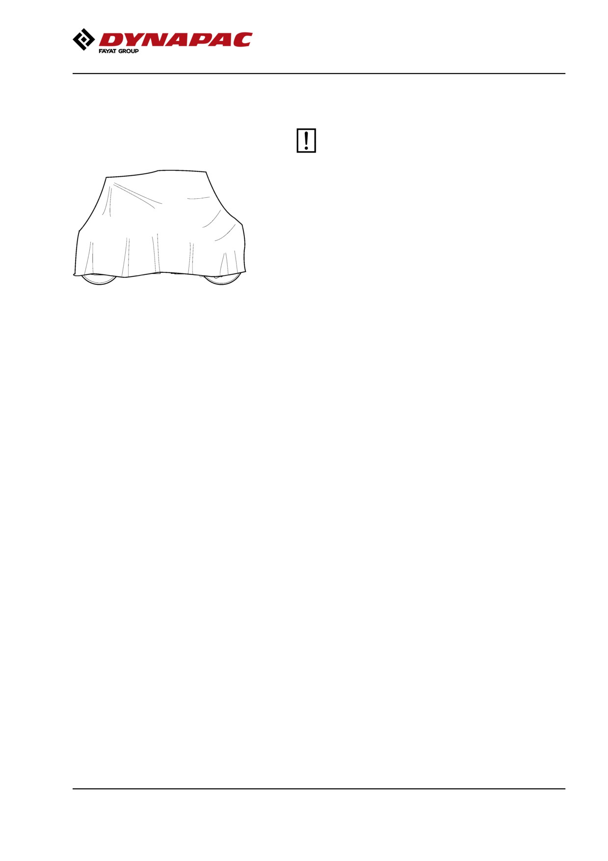
Fig. Roller weather protection
avoid rusting.
Treat exposed parts with anti-rust agent, lubricate the
machine thoroughly and apply grease to unpainted
surfaces.
Engine
* Refer to the manufacturer’s instructions in the engine
manual that is supplied with the roller.
Battery
* Dismantle the battery/batteries from the machine,
clean the outside and maintenance charge.
Air cleaner, exhaust pipe
* Cover the air cleaner or its opening with plastic or
tape. Also cover the exhaust pipe opening. This is to
avoid moisture entering the engine.
Fuel tank
Fill the fuel tank completely full to prevent
condensation.
Hydraulic reservoir
Fill the hydraulic reservoir to the uppermost level mark
(see under the heading ‘Every 10 hours of operation.’)
Tires (All-weather)
Check that tire pressure is 110 kPa (1.1 kp/cm 2 ), (16
psi).
2019-11-05
79
Long-term parking
Hoods, tarpaulin
* Lower the instrument cover over the instrument
panel.
* Cover the entire roller with a tarpaulin. A gap must
be left between the tarpaulin and the ground.
* If possible, store the roller indoors and ideally in a
building where the temperature is constant.
2019-11-05
80
Miscellaneous
Miscellaneous
Lifting
Locking the articulation
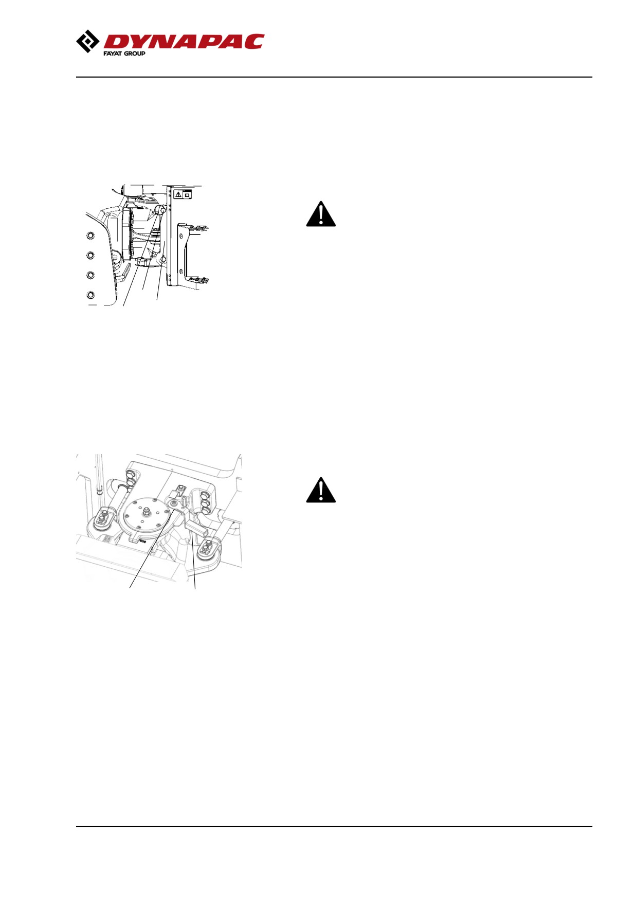
Articulation must be locked to prevent inadvertent
turning before lifting the roller.
Turn the steering wheel to the straight ahead position.
Activate the parking brake.
3
Pull out the upper locking pin (2) fitted with a wire, and
1
2
pull out the locking dowel (3) fitted with a wire.
Fold down the locking arm (1) so that it rests against
Fig. Steering joint lock
1. Locking arm
the drum frame.
2. Locking pin
3. Locking dowel
Reinstall the locking dowel (3) in the uppermost
locking lug, and secure the dowel in position with the
locking pin (2).
Locking the articulation
Articulation must be locked to prevent inadvertent
turning before lifting the roller.
Turn the steering wheel to the straight ahead position.
Activate the parking brake.
Front frame shall be in line with the rear frame.
2
1
Fig. Steering joint lock, locked
Lift lock in the handle (1) while it is turned clockwise.
1. Lock handle
2. Locking dowel
Make sure dowel (2) gets in position as illustrated.
Arm must be in contact with the surface of the molded
holder.
If this is not done, it's likely that the machine halves
are out of line, steer then the machine so this is
happening.
2019-11-05
81
Miscellaneous
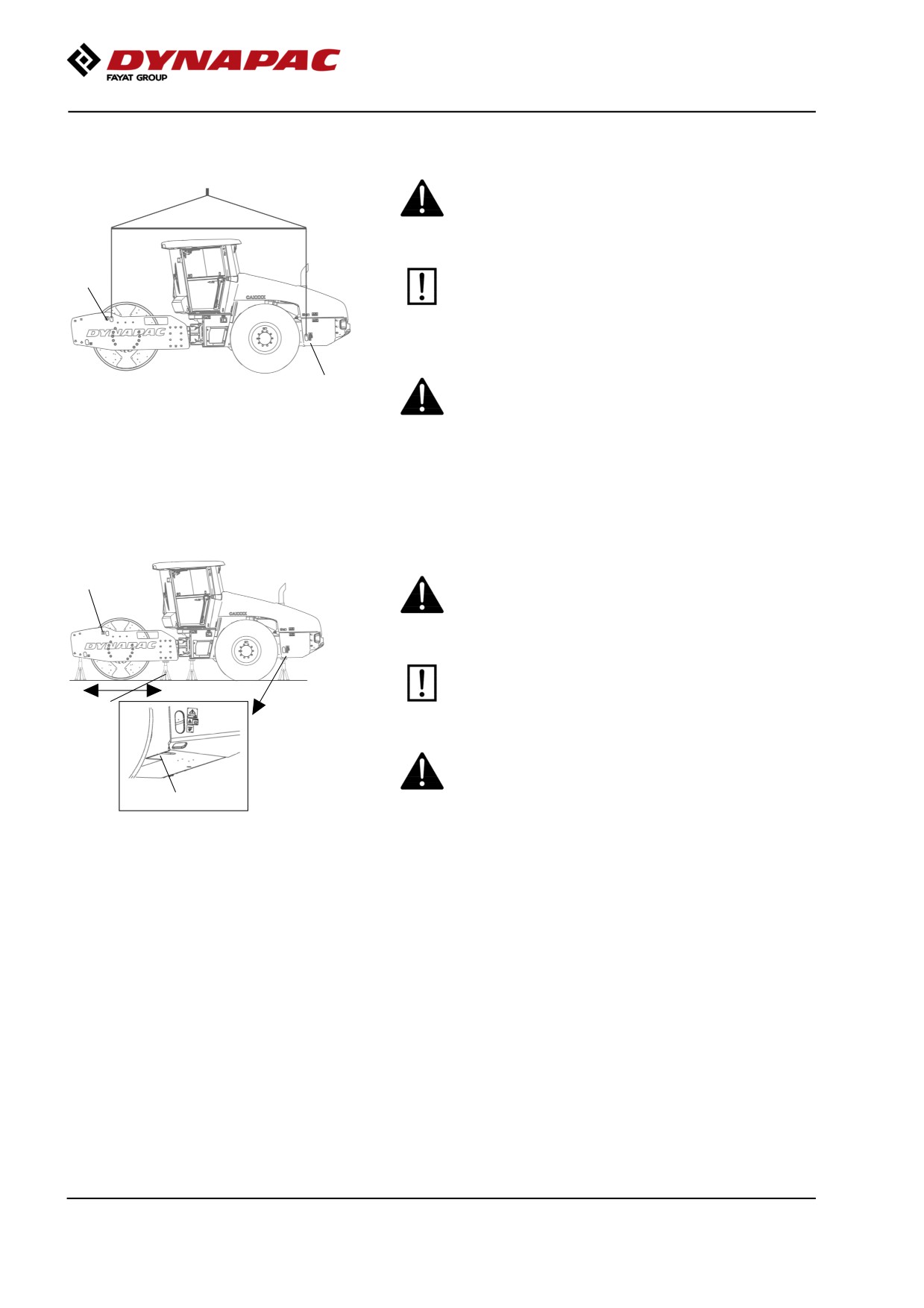
Weight: refer to the hoisting plate on the roller
Lifting the roller
The machine’s gross weight is specified on the
hoisting plate (1). Refer also to the Technical
specifications.
1
Lifting equipment such as chains, steel wires,
straps and lifting hooks must be dimensioned in
accordance with the relevant safety regulations
for the lifting equipment.
Stand well clear of the hoisted machine! Make sure
1
that the lifting hooks are properly secured.
Fig. Roller prepared for lifting
1. Lifting plate
Weight: refer to the hoisting plate on the
roller
Lifting the roller with jack:
1
The machine’s gross weight is specified on the
hoisting plate (1). Refer also to the Technical
specifications.
The lifting device such as a jack (2), or
equivalent, must be dimensioned according to the
2
safety regulations for lifting devices.
Do not go under a lifted load! Make sure that the
lifting device is secure in its position, and on a
level and stable suface.
3
Figure. Roller lifted with jack
1. Lifting plate
2. Jack
You are recommended to lift the machine with a jack
3. Marking
or similar positioned at the marking (3) and/or at
alternative locations as illustrated. Lifting at any other
place can result in damage to the machine or personal
injury.
Regarding the drum frame, axle stands can be placed
along the entire side plates and cross members if
necessary.
2019-11-05
82
Miscellaneous
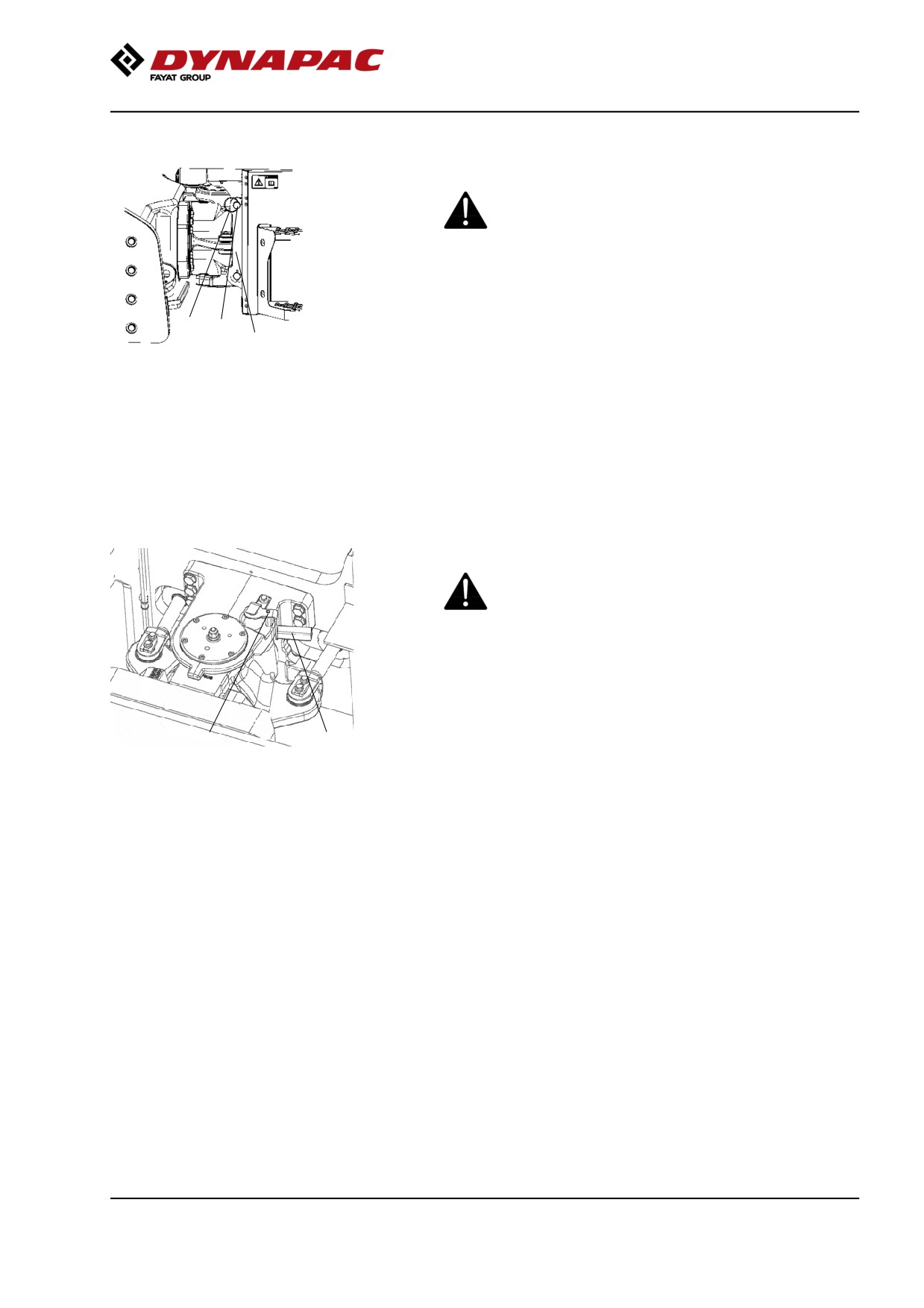
Unlocking the articulation
Remember to restore the steering joint lock on the
steering joint to open before operating.
Fold up the locking arm (1) and secure it in upper the
locking lug with the locking dowel (3). Insert the
2
3
locking pin (2) to secure the locking dowel (3).
1
Fig. Steering joint lock
1. Locking arm
2. Locking pin
3. Locking dowel
Unlocking the articulation
Remember to restore the steering joint lock on the
steering joint to open before operating.
Lift lock in the handle while turning it counterclockwise.
Make sure lock gets in position on the dowel by trying
2
1
to turn the handle clockwise or counterclockwise
Fig. Steering joint lock, open
without lifting the lock.
1. Lock handle
2. Locking dowel
Towing/Recovering
The roller can be moved up to 300 meters (330 yards)
using the instructions below.
2019-11-05
83
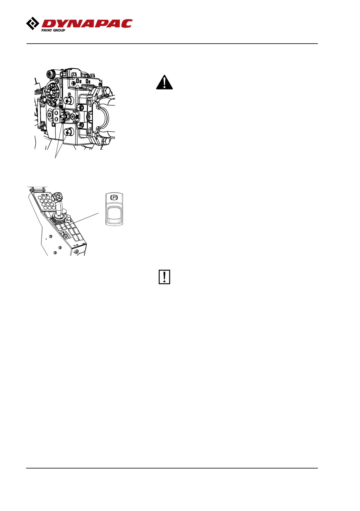
Miscellaneous
Short distance towing with the engine running
Activate the parking brake, and temporarily stop
the engine. Chock the wheels to prevent the roller
from moving.
Open the hood and make sure that the propulsion
pump is accessible.
On the pump there are two by-pass valves (1) (hex
screws), which should be turned three turns
anticlockwise to put the system in by-pass mode.
1
This function enables a machine to be moved.
Fig. Propulsion pump
1. By-pass valves
Start the engine and allow it to idle.
Deactivate the brake with the parking brake knob(2).
Move the forward/reverse lever forwards or backwards
2
just outside the neutral position. If the control is in
neutral, the brakes are still activated.
The roller can now be towed and can also be steered
if the steering system is otherwise functioning.
To disengage the by-pass mode, turn back the
by-pass valves (1) three turns clockwise.
The machine must not be moved at a speed
Fig. Control panel
higher than 3 km/h (2 mph), and no more than
2. Parking brake knob
300 meters (330 yards). Otherwise there is a risk
of damaging the drives. Be sure to reset the
towing valves (by turning them three turns
clockwise) after towing.
2019-11-05
84
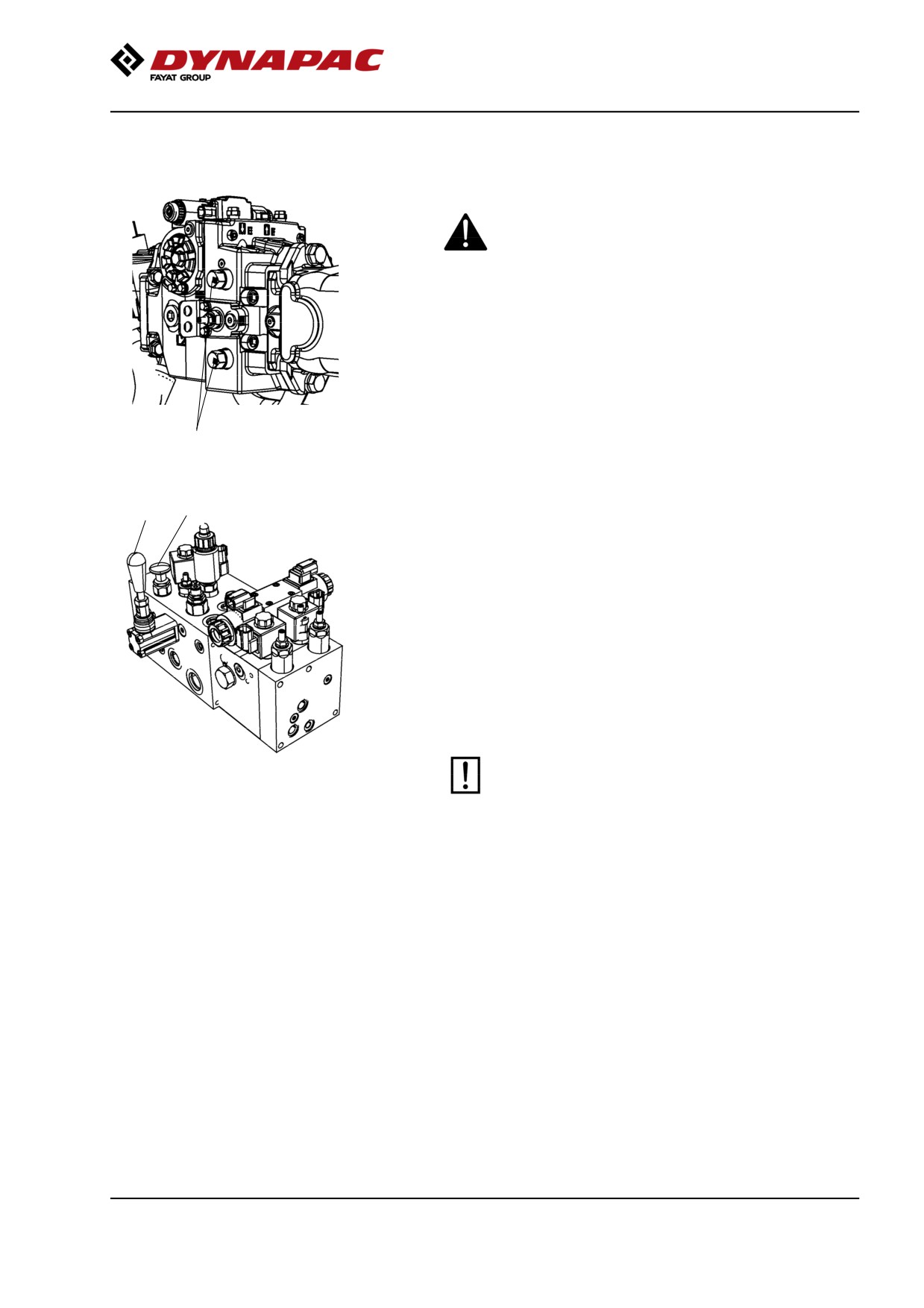
Miscellaneous
Short distance towing when the engine is
inoperative.
Chock the wheels to prevent the roller from
moving when the brakes are hydraulically
disengaged.
Open the hood and make sure that the propulsion
pump is accessible.
On the pump there are two by-pass valves (1) (hex
screws), which should be turned three turns
anticlockwise to put the system in by-pass mode.
1
This function enables a machine to be moved.
Fig. Propulsion pump
1. By-pass valve
3
The release pump for the brakes is located on the
2
valve block, which is positioned in the rear of the
engine compartment.
Press the break release button (3).
Pump with the arm (2) until the brakes are released.
The roller can now be towed.
After towing, pull the brake release button (3) up.
To disengage the by-pass mode, turn back the hex
screws (1) three turns clockwise.
The machine must not be moved at a speed
higher than 3 km/h (2 mph), and no more than 300
Fig. Valve block, engine compartment
meters (330 yards). Otherwise there is a risk of
2. Pump arm
damaging the drives. Be sure to reset the towing
3. Brake release button
valves (by turning them three turns clockwise)
after towing.
2019-11-05
85
Miscellaneous
Towing the roller
When towing/recovering, the roller must be braked
by the towing vehicle. A towing bar must be used
as the roller has no brakes.
The roller must be towed slowly, max. 3 km/h (2
mph) and only towed short distances, max. 300 m
(330 yards).
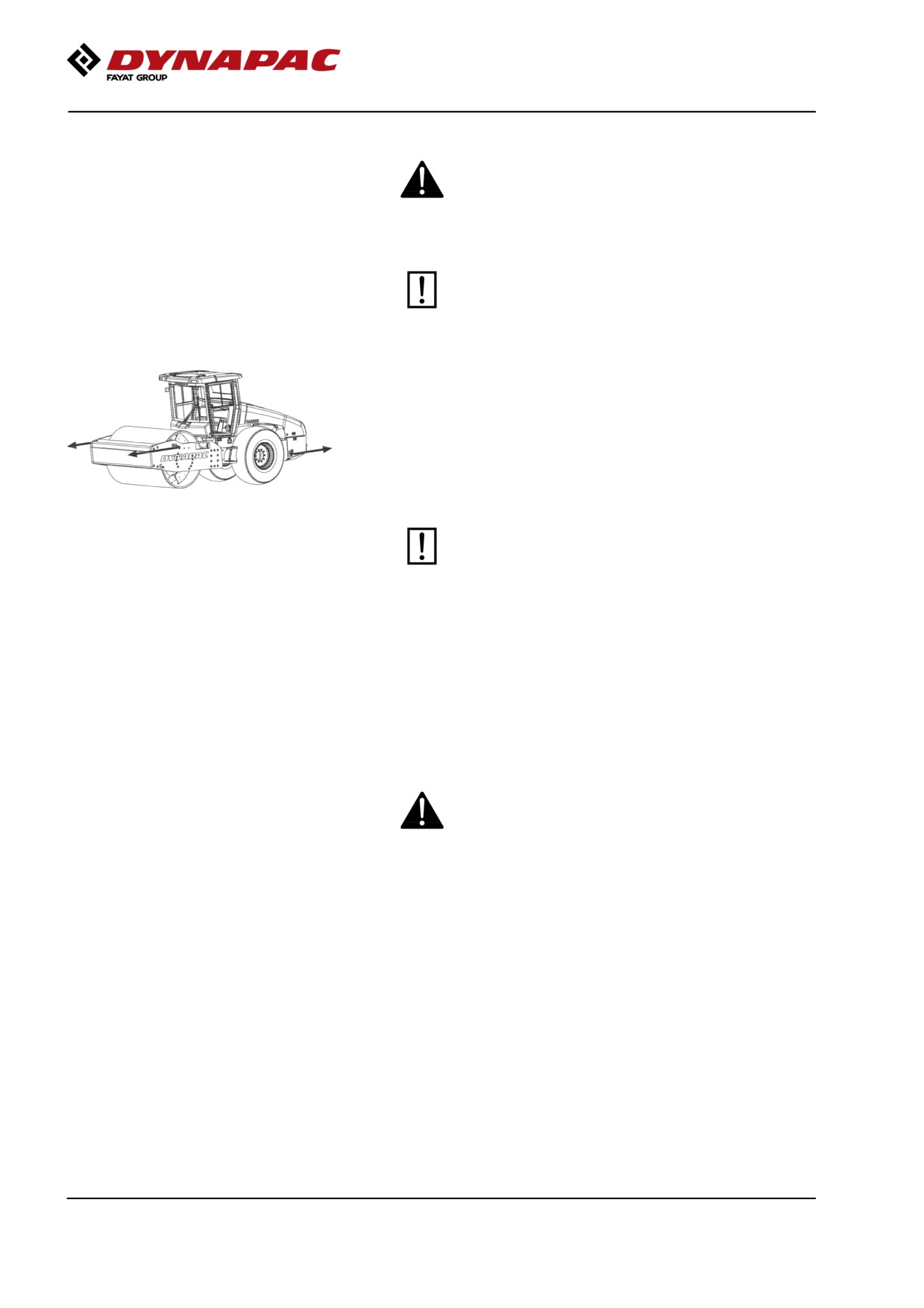
When towing/retrieving a machine, the towing device
must be connected to both lifting holes. The pulling
force must act longitudinally on the machine as shown
in the figure. Maximum gross pulling force 200 kN (44
960 lbf).
Fig. Towing
Reverse the towing preparations according to
alternative 1 or 2 in the preceding section.
Transport
Tie-down and secure the machine according to the
Cargo Securing Certificate for the specific machine if
this is avaliable and applicable.
If not, tie down and secure the machine according to
the cargo securing rules that are valid for the country
where the transport takes place.
Never lash over the machine’s articulated joint, nor
over the machine’s operator platform.
Before securing the machine ensure that :
• the parking brake is applied and in good working condition
• the articulated joint is in closed position
• the machine is centered laterally on the platform
• the lashings are in good condition and fulfills the
corresponding rules for transport securing.
2019-11-05
86
Miscellaneous
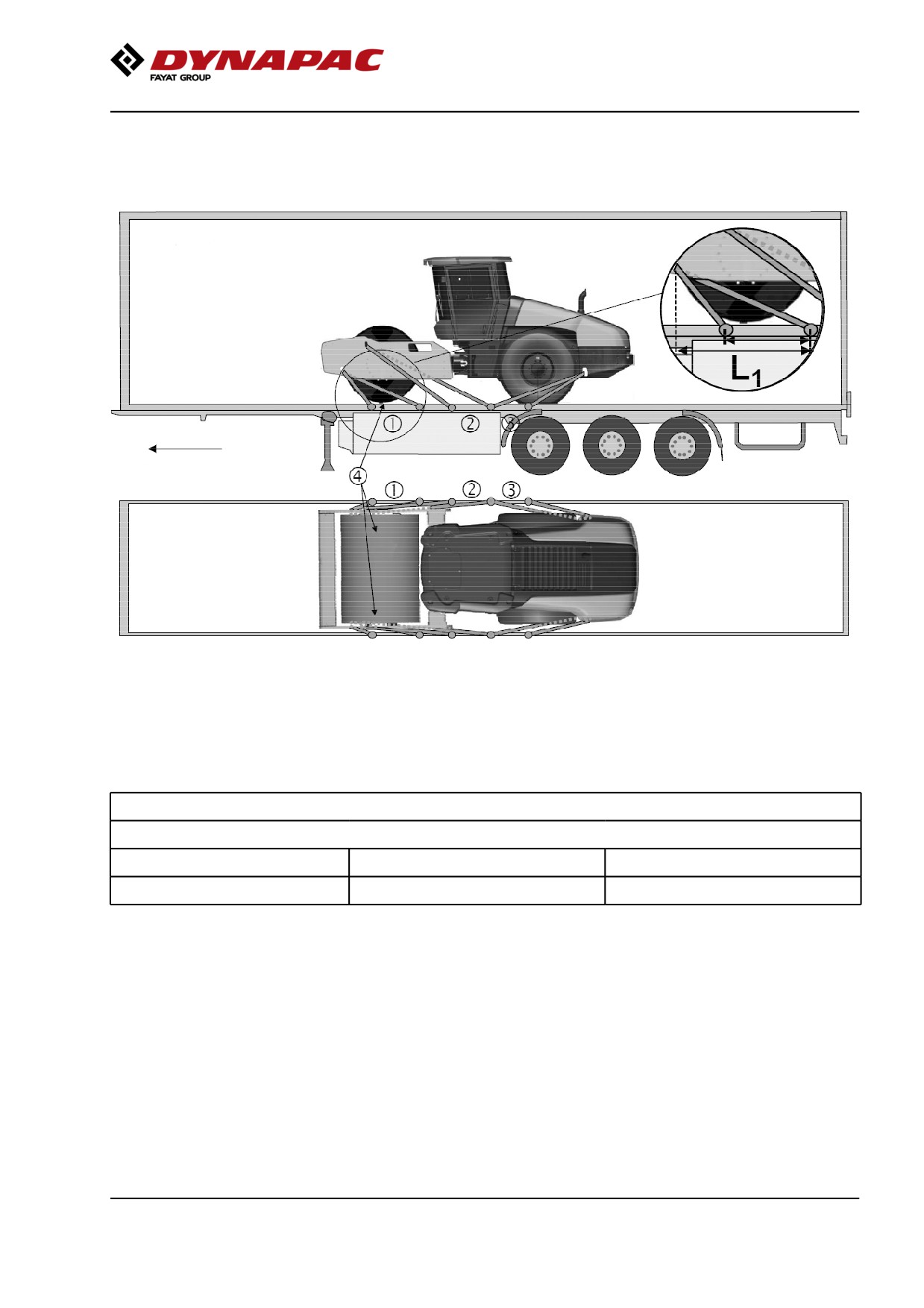
Securing CA2500-CA4600 for loading
Securing the CA2500-4600D/PD vibratory roller from
Dynapac for transport.
Roller loaded in forward
direction
Direct of travel
1 - 3
= double lashings, i.e. one lashing with two parts secured to two different lashing mounts,
symmetrically located on the right and left sides.
4
= rubber
The lashings' permitted distance interval in meters
(1 - 3: Double lashings, LC at least 1.7 tonnes (1700 daN), STF 300 kg (300daN))
Double L1
Double L2
Double L3
0,9 - 2,5
0,9 - 2,5
0,1 - 2,5
For lashing 1 is L1 the distance between the lashing point on the edge of the platform and the point directly sideways
from the lashing point on the roller perpendicular to the platform edge. The relationship for lashings L2 and L3 is the
same.
2019-11-05
87
Miscellaneous
Load carrier
-
When loaded, the vibratory roller is centered laterally on the platform (± 5 cm).
-
The parking brake is applied and in good working condition, and the articulated joint lock is
closed.
-
The drum is placed on a rubber liner, so that the static friction between the surfaces is at least
0.6.
-
The contact surfaces must be clean, wet or dry, and free from frost, ice and snow.
-
The lashing mounts on the load carrier have LC/MSL at least 2 tonnes.
Lashings
-
The lashings comprise a lashing strap or chain with a permitted load (LC/MSL) of at least 1.7
tonnes (1,700 daN) and a pre-tension STF of at least 300 kg (300 daN). The lashings are
re-tightened as required.
-
Each of lashings 1-3 is either a double or two single lashings. A double lashing runs in a sling
through a lashing point or around a machine part and down into two different mounts on the
platform.
-
Lashings in the same direction are placed in different lashing mounts on the trailer. Lashings
that are pulled in opposite directions may be placed in the same lashing mount, however.
-
The lashings are as short as possible.
-
The lashing hooks must not lose grip if the lashings become slack.
-
The lashings are protected against sharp edges and corners.
-
The lashings are located symmetrically in pairs on the right and left sides.
2019-11-05
88
Operating instructions - Summary
Operating instructions - Summary
1.
Follow the SAFETY INSTRUCTIONS specified in the Safety Manual.
2.
Ensure that all instructions in the MAINTENANCE section are followed and the
steering hitch lock is unlocked.
3.
Turn the master switch to the ON position.
4.
Move the forward/reverse lever to the NEUTRAL position. Sit down in the seat.
5.
Activate the parking brake.
6.
Disengage the emergency stop.
7.
Set the engine speed switch to idle (LO).
8.
Start the engine and allow it to warm up.
9.
Set the engine speed switch to Mid/working mode.
10. Deactivate the parking brake.
11. Drive the roller. Operate the F/R lever with care.
12. Test the brakes. Remember that the braking distance will be longer if the
hydraulic fluid is cold.
13. Set the transportation/working mode button in position working mode.
14. Use vibration only when the roller is in motion.
15. IN AN EMERGENCY:
- Press the EMERGENCY STOP.
- Hold the steering wheel firmly.
- Brace yourself for a sudden stop.
16. When parking:
- Activate the parking brake.
- Switch off the engine and block the drum and wheels if the roller is on an inclined
surface.
17. When lifting: - Refer to the relevant section in the Instruction Manual.
18. When towing: - Refer to the relevant section in the Instruction Manual.
19. When transporting: - Refer to the relevant section in the Instruction Manual.
20. When recovering - Refer to the relevant section in the Instruction Manual.
2019-11-05
89
Operating instructions - Summary
2019-11-05
90
Preventive maintenance
Preventive maintenance
Complete maintenance is necessary for the machine
to function satisfactorily and at the lowest possible
cost.
The Maintenance section includes the periodic
maintenance that must be carried out on the machine.
The recommended maintenance intervals assume that
the machine is used in a normal environment and
working conditions.
Acceptance and delivery inspection
The machine is tested and adjusted before it leaves
the factory.
On arrival, before delivery to the customer, delivery
inspection must be conducted as per the check list in
the warranty document.
Any transport damage must be reported immediately
to the transport company, as this is not covered by the
product warranty.
Warranty
The warranty is only valid if the stiplulated delivery
inspection and the separate service inspection have
been completed as per the warranty document, and
when the machine has been registered for starting
under the warranty.
The warranty is not valid if damage has been caused
by inadequate service, incorrect use of the machine,
the use of lubricants and hydraulic fluids other than
those specified in the manual, or if any other
adjustments have been made without the requisite
authorisation.
2019-11-05
91
Preventive maintenance
2019-11-05
92
Maintenance - Lubricants and symbols
Maintenance - Lubricants and symbols
Always use high-quality lubricants and the
amounts recommended. Too much grease or
oil can cause overheating, resulting in rapid
wear.
Fluid volumes
Rear axle
- Differential
16,5 liters
17.4 qts
- Planetary gear
1,7 liters/side
1.8 qts/side
Rear axle (No-Spin), (optional)
- Differential
12,5 liters
13.2 qts
- Planetary gear
1,9 liters/side
2.0 qts/side
Drum
- Drum gear
2,5 liter
2.6 qts
- Drum cartridge
2,2 liters/side
2.3 qts/side
Hydraulic reservoir
41 liters
10.8 gal
Oil in hydraulic system
80 liters
21.1 gal
Diesel engine
- Lubricating oil
11 liter
11.6 qts
- Coolant, without cab (IIIA/T3)
24 liters
25.4 qts
- Coolant, without cab (IIIB/T4i)
26 liters
27.5 qts
- Coolant, with cab (IIIA/T3)
26,2 liters
27.7 qts
- Coolant, with cab (IIIB/T4i)
28,2 liters
29.8 qts
Other fuel and lubricants are required when
operating in areas with extremely high or
extremely low ambient temperatures. See the
‘Special instructions’ chapter, or consult
Dynapac.
ENGINE OIL
Air temperature -15°C - +50°C
Dynapac Engine oil 200
P/N 4812161855 (5 liters),
(5°F-122°F)
P/N 4812161856 (20 liters)
HYDRAULIC FLUID Air temperature -15°C - +50°C
Dynapac hydraulic 300
P/N 4812161868 (20 liters),
(5°F-122°F)
P/N 4812161869 (209 liters)
Ambient air temperature above Shell Tellus S2 V100
+40°C (104°F)
2019-11-05
93
Maintenance - Lubricants and symbols
BIOLOGICAL
Air temperature -10°C - +35°C
PANOLIN HLP Synth 46
HYDRAULIC FLUID,
(14°F-95°F)
PANOLIN
When it leaves the factory, the
machine may be filled with
biologically degradable fluid.
The same type of fluid must be
used when changing or topping
up.
DRUM OIL
Air temperature -15°C - +40°C
Dynapac Drum Oil 1000
P/N 4812161887 (5 liters),
(5°F-104°F)
P/N 4812161888 (20 liters)
GREASE
Dynapac Roller Grease P/N 4812030096
(0.4kg)
FUEL
See engine manual.
-
-
TRANSMISSION OIL Air temperature -15°C - +40°C
Dynapac Gear oil 300
P/N 4812161883 (5 liters),
(5°F-104°F)
P/N 4812161884 (20 liters)
Air temperature 0°C (32°F) -
Shell Spirax S3 AX
above +40°C (104°F)
85W-140, API GL-5 or
equivalent.
COOLANT
Anti-freeze protection down to
Dynapac coolant 100
P/N 4812161854 (20 liters)
about -37°C (-34.6°F)
(mixed 50/50 with water)
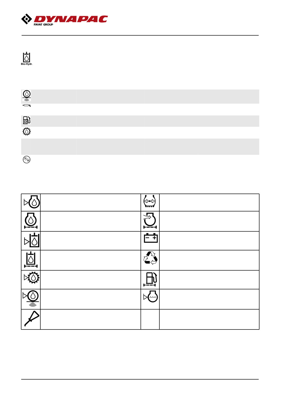
Maintenance symbols
Engine, oil level
Tyre pressure
Engine, oil filter
Air filter
Hydraulic reservoir, level
Battery
Hydraulic fluid, filter
Recycling
Transmission, oil level
Fuel filter
Drum, oil level
Coolant, level
Oil for lubrication
2019-11-05
94
Maintenance - Maintenance schedule
Maintenance - Maintenance schedule
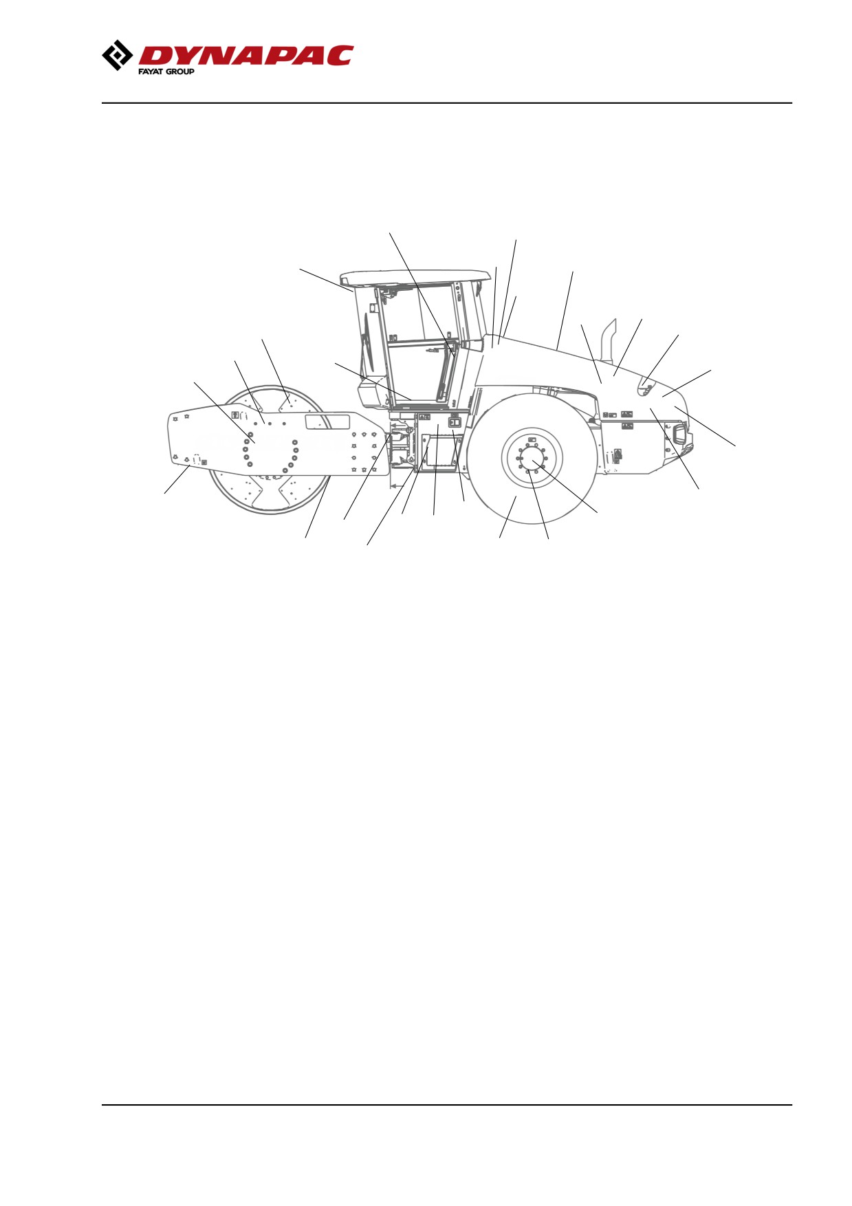
Service and maintenance points
11
1
33,34
5
31,32
6,7,10
2, 3
25
16
4
13
27
19
12
8
7
14
15
9
22,23
17,18
11
14
26
21
20
Fig. Service and maintenance points
1.
Diesel fuel, filling
14. Scrapers
27. Seat bearing *
2.
Oil level, diesel engine
15. Battery
28. Steering chain *
3.
Fuel filter, fuel pre-filter
16. Rubber elements and fastening
screws
4.
Air filter
17. Steering hitch
5.
Engine cover, hinges
18. Steering cylinders, x2
31. Water cooler
6.
Hydraulic reservoir, sight glass
19. Drive belts
32. Hydraulic fluid cooler
7.
Bleeding filter
20. Wheel nuts
33. Fresh air filter *
8.
Hydraulic fluid filter, x1
21. Tires, pressure
34. Air conditioning *
9.
Drainage, hydraulic fluid
22. Rear axle, differential
reservoir
10. Hydraulic fluid, filling
23. Rear axle, planetary gears, 2 pcs.
11. Fuse box(es), main fuses
12. Drum cartridge, filling, 2 fillers
25. Oil filter, diesel engine
13. Drum gearbox
26. Draining, fuel tank *
* Optional equipment
General
Periodic maintenance should be carried out after the
number of hours specified. Use the daily, weekly etc.
periods where number of hours cannot be used.
2019-11-05
95
Maintenance - Maintenance schedule
Remove all dirt before filling, when checking
oils and fuel and when lubricating using oil or
grease.
The manufacturer’s instructions found in the
engine manual also apply.
Specific maintenance and checks on diesel
engines must be carried out by the engine
supplier’s certified personnel.
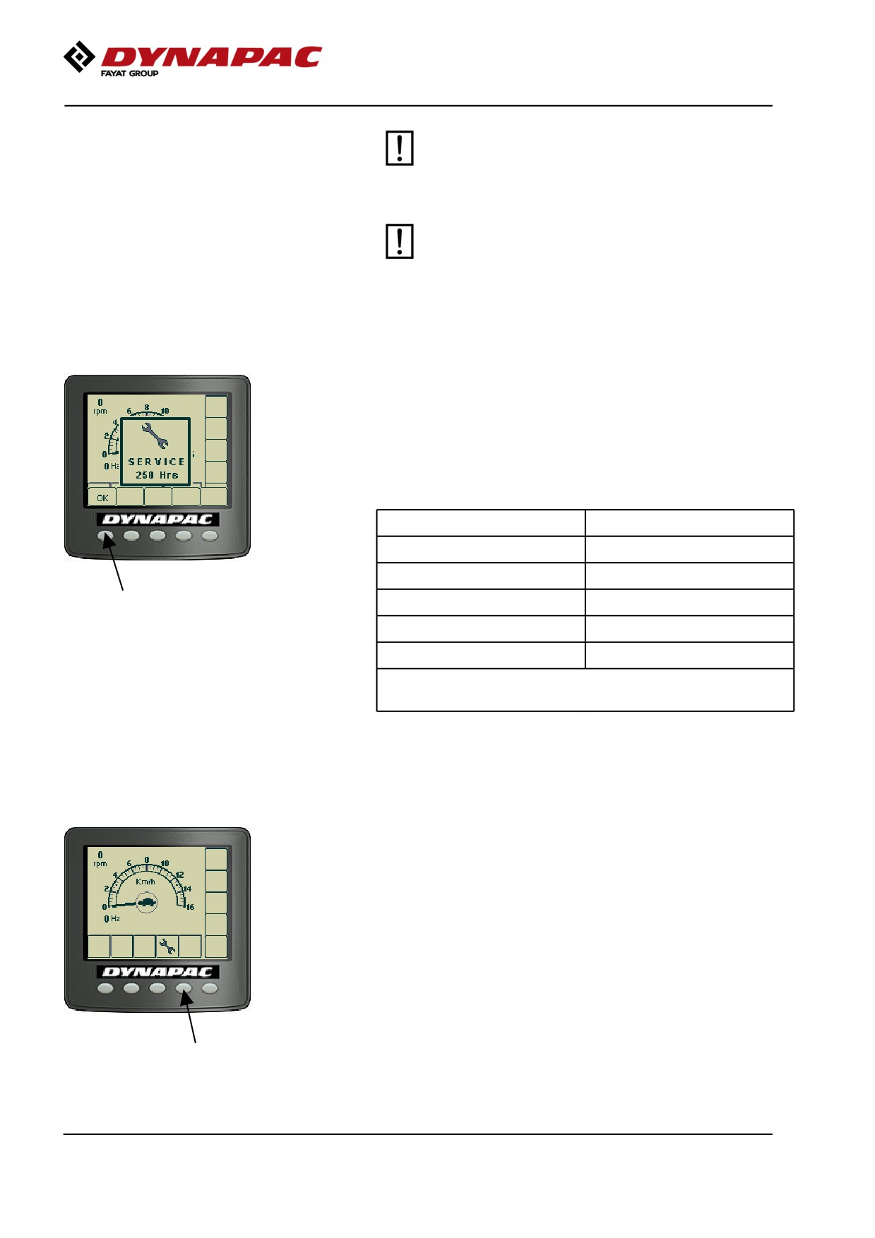
Periodic service (service message) - Optional
A Service message (Periodic Service) is shown in the
display 15 hours before First Service (50h).
For Periodic Service (250h-1000h) a Service message
is shown in the same way but with the difference that it
is shown 30 hours before the Periodic service interval.
Service interval
Display start
50h
35h
250h
220h
500h
470h
750h
720h
1000h
970h
The message continues to be displayed for 15
engine starts or until it is reset by the Service tool.
The alarm message shown is acknowledged by
pressing the "OK" button on the display.
A Service symbol is now visible at the bottom of the
display screen.
2019-11-05
96
Maintenance - Maintenance schedule
Every 10 hours of operation (Daily)
Refer to the contents to find the page number of the
sections referred to !
Pos. in fig
Action
Comment
Before starting up for the first time on that day
14
Check the scraper setting
Check for free circulation of cooling air
31
Check coolant level
Refer to the engine manual
2
Check the engine oil level
Refer to the engine manual
1
Refuel
6
Check fluid level in hydraulic reservoir
Test the brakes
After the FIRST 50 hours of operation
Refer to the contents to find the page number of the
sections referred to !
Pos. in fig
Action
Comment
8
Change the hydraulic fluid filter
12
Change the drum cartridge oil
20
Check the wheel-nuts are tightened
21
Check the tire pressure
22
Change oil in rear axle differential
23
Change oil in the rear axle planetary gearing
13
Change the oil in the drum gearbox
Only for machines with
drum gearbox.
17
Steering hitch - Tightening
Every 50 hours of operation (Weekly)
Refer to the contents to find the page number of the
sections referred to!
Pos.
Action
Comment
in fig
Check that hoses and couplings are not leaking
2019-11-05
97
Maintenance - Maintenance schedule
Every 250 / 750 / 1250 / 1750 hours of operation
Refer to the contents to find the page number of the
sections referred to !
Pos. in fig
Action
Comment
12
Check the oil level in drum cartridges
12
Cleaning the ventilation screws in the drum
cartridges
23,22
Check the oil level in rear axle/planetary gears
13
Check the oil level in drum gearbox
Only for machines with
drum gearbox
32,31
Clean the coolers
16
Check rubber elements and bolted joints
15
Check batteries
34
Check the AC
Optional
Every 500 / 1500 hours of operation
Refer to the contents to find the page number of the
sections referred to !
Pos. in fig
Action
Comment
4
Inspect the filter element in the air cleaner
Replace as required
32,31
Clean the coolers
12
Check the oil level in drum cartridges
23,22
Check the oil level in rear axle/planetary gears
13
Check the oil level in drum gearbox
Only for machines with
drum gearbox
2,25
Change the engine oil and oil filter. *)
Refer to the engine manual
*) 500h or once every 6
months.
3
Replace the fuel filter
Refer to the engine manual
3
Replace the fuel pre-filter
Refer to the engine manual
5
Lubricate controls and joints
27,28
Lubricate seat bearing/steering chain
Optional
Check the engine's valve clearance (after the first
Refer to the engine manual
500 h)
2019-11-05
98
Maintenance - Maintenance schedule
Every 1000 hours of operation
Refer to the contents to find the page number of the
sections referred to !
Pos. in fig
Action
Comment
8
Change the hydraulic fluid filter
12
Check the oil level in drum cartridges
4
Inspect the filter element in the air cleaner
Replace as required
22
Change oil in rear axle differential
23
Change oil in the rear axle planetary gearing
13
Change the oil in drum gearbox
Only for machines with
drum gearbox
32,31
Clean the coolers
3
Replace the fuel filter
Refer to the engine manual
3
Replace the fuel pre-filter
Refer to the engine manual
2,25
Change the engine oil and oil filter. *)
Refer to the engine
manual*) 500h or once
every 6 months.
7
Check bleeder filter on hydraulic reservoir
9
Drain the condensate from hydraulic reservoir
26
Drain condensate from fuel tank
Optional
33
Replace the fresh air filter in the cab
Optional
19
Check belt tension in the drive belt system
Refer to the engine manual
17
Steering hitch - Tightening
2019-11-05
99
Maintenance - Maintenance schedule
Every 2000 hours of operation
Refer to the contents to find the page number of the
sections referred to !
Pos. in fig
Action
Comment
6,10
Change the hydraulic fluid
8
Change the hydraulic fluid filter
12
Change the oil in the drum cartridges
4
Inspect the filter element in the air cleaner
Replace as required
22
Change oil in rear axle differential
23
Change oil in the rear axle planetary gearing
13
Change the oil in the drum gearbox
Only for machines with
drum gearbox
32,31
Clean the coolers
3
Replace the fuel filter
Refer to the engine manual
3
Replace the fuel pre-filter
Refer to the engine manual
2,25
Change the engine oil and oil filter. *)
See the engine's
instruction manual
*) 500 h or once every 6
months.
27,28
Grease the steering bearing / steering chain
Optional
7
Check bleeder filter on hydraulic reservoir
9
Drain the condensate from hydraulic reservoir
26
Drain condensate from fuel tank
Optional
34
Overhaul air conditioning
Optional
Check engine's valve clearances
Refer to the engine manual
19
Check belt tension in the drive belt system
Refer to the engine manual
Replace the ventilation filter in the crankcase *)
Refer to the engine manual
*) only applies to Stage
IIIB/Tier 4i
17
Steering hitch - Tightening
2019-11-05
100
Maintenance - Maintenance schedule
Every other year
Refer to the contents to find the page number of the
sections referred to !
Pos. in fig
Action
Comment
31
Change the coolant (glycol)
10
Change the fluid in the hydraulic reservoir *)
*) not for PANOLIN
hydraulic oil
12
Change the oil in drum cartridges
12
Cleaning the ventilation screws in the drum
cartridges
4
Inspect the filter element in the air cleaner
Replace as required
22
Check the oil level in the rear axle's differential
23
Check oil level in rear axle's planetary gearing
13
Change the oil in drum gearbox
Only for machines with
drum gearbox
16
Check rubber elements and bolted joints
9
Drain the condensate from hydraulic reservoir
26
Drain condensate from fuel tank
Optional
19
Check belt tension in the drive belt system
Refer to the engine manual
2019-11-05
101
Maintenance - Maintenance schedule
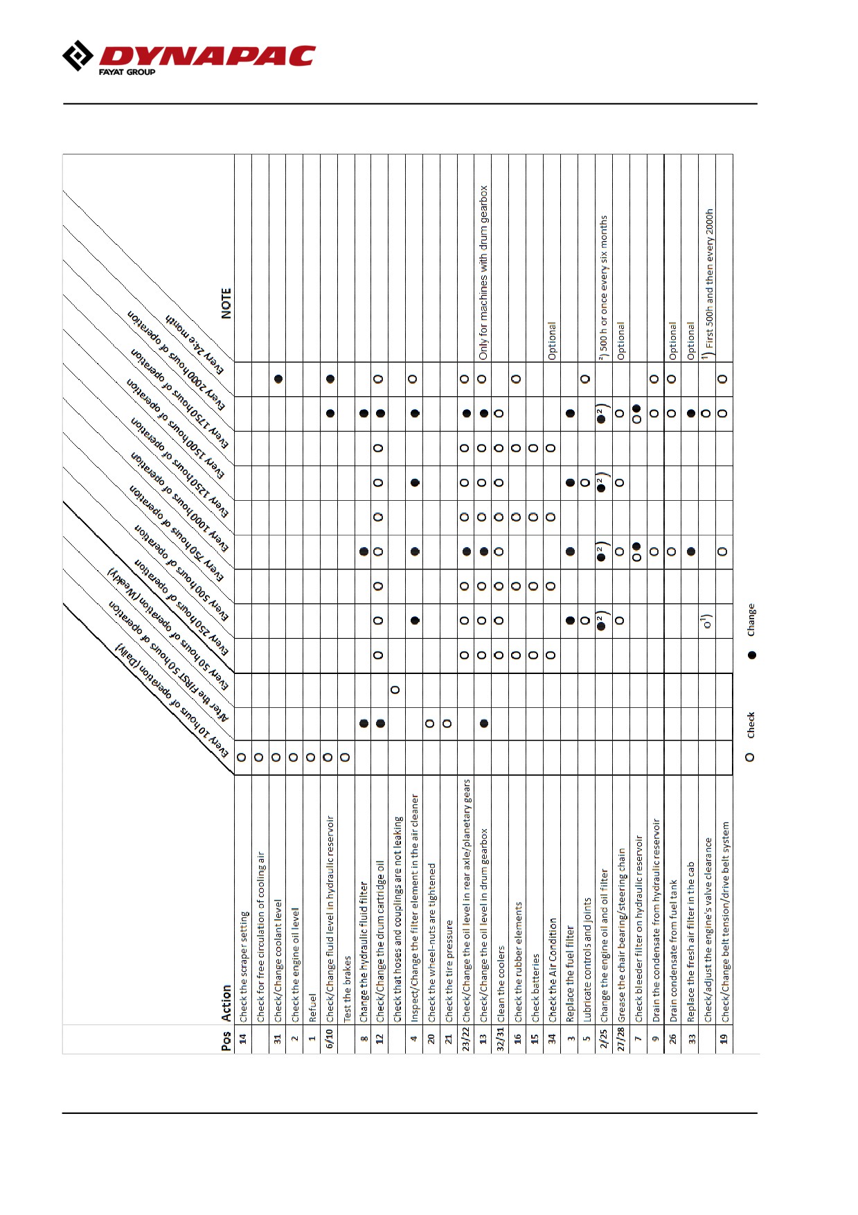
Service - Checklist
2019-11-05
102
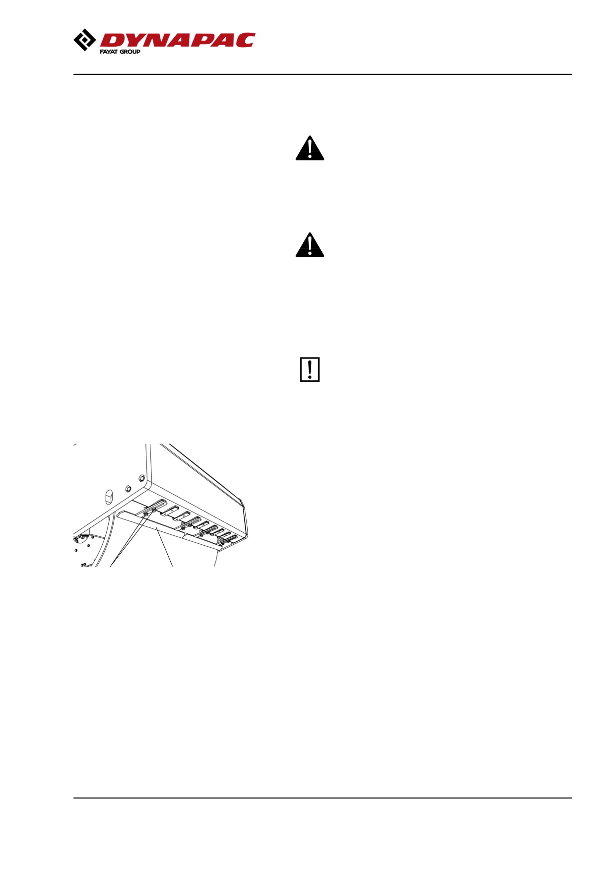
Maintenance, 10h
Maintenance, 10h
Every 10 hours of operation (Daily)
Park the roller on a level surface.
The engine must be switched off and the
parking brake activated when checking or
adjusting the roller, unless otherwise specified.
Ensure that there is good ventilation (air
extraction) if the engine is run indoors. Risk of
carbon monoxide poisoning.
Scrapers - Check, adjustment
It is important to consider movement of the drum
when the machine turns, i.e., the scrapers can be
damaged or wear of the drum may increase if
adjustment is made closer than the values stated.
If necessary, adjust distance to the drum as follows:
Loosen the screws (2) on the scraper attachment.
Then adjust the scraper blade (1) to 25 mm (1 in) from
the drum.
Tighten the screws (2).
Repeat the procedure for the other scraper blades (x4).
2
1
Fig. Scrapers
1. Scraper blade (x 4)
2. Screws
2019-11-05
103
Maintenance, 10h
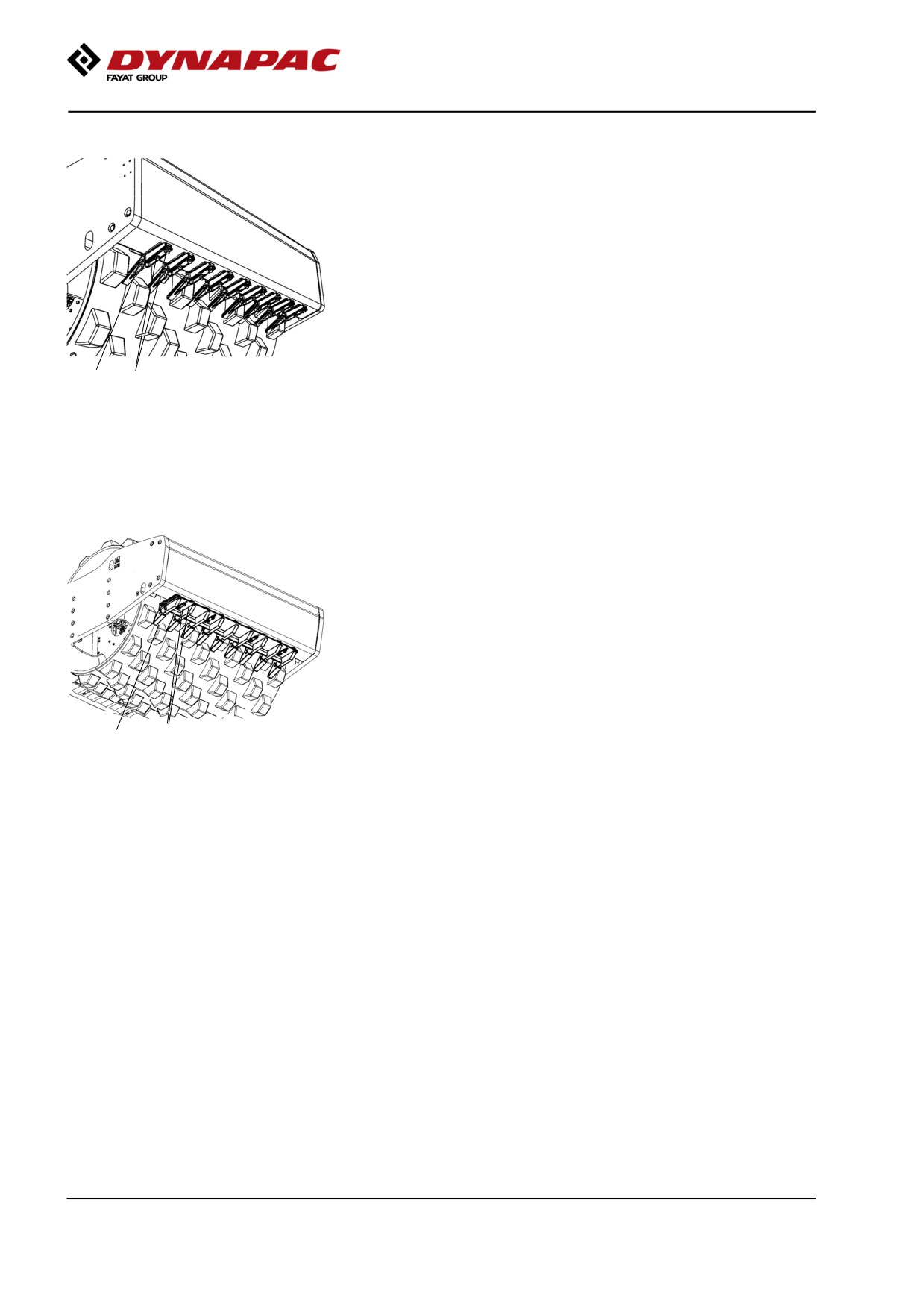
Scrapers, Pad-drum
Undo the screws (1), then adjust each scraper tooth
(2) to 25 mm (1.0 in) between scraper tooth and drum.
Center each scraper tooth (2) between the pads.
Tighten the screws (1).
2
1
Fig. Scrapers
1. Screws
2. Scraper teeth (x 18)
Scrapers (Heavy duty), Pad drum
Undo the screws (1), then adjust/center 25 mm (1.0 in)
between the scraper teeth (2) and drum.
Center each scraper tooth (2) between the pads.
Tighten the screws (1).
1
2
Fig. Scrapers
1. Screws
2. Scraper teeth
2019-11-05
104
Maintenance, 10h
Flexible scrapers (Optional)
Loosen the screws (2).
Then, adjust the scraper blade (1) so that it lightly
touches the drum.
Tighten the screws (2).
2
1
2
1
Fig. Scrapers
1. Scraper blade
2. Screws
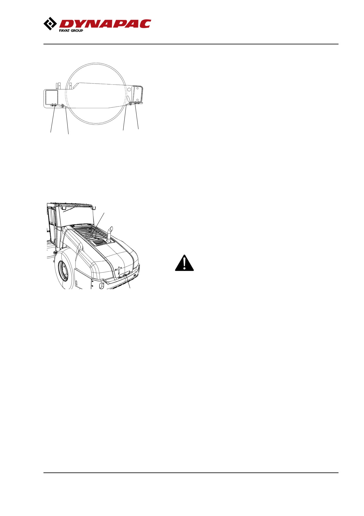
Air circulation - Check
Ensure that the engine has free circulation of cooling
2
air through the protective grille in the hood.
To open the engine hood, turn the lock handle (1)
upward. Raise the hood to its fully open position,
checking that the red safety catch on the left gas
spring is latched.
If the gas-springs for the hood are loosend and the
hood is raised to its upper position - block the
hood so that it cannot fall.
1
Fig. Engine hood
1. Hood lock
2. Protective grille
2019-11-05
105
Maintenance, 10h
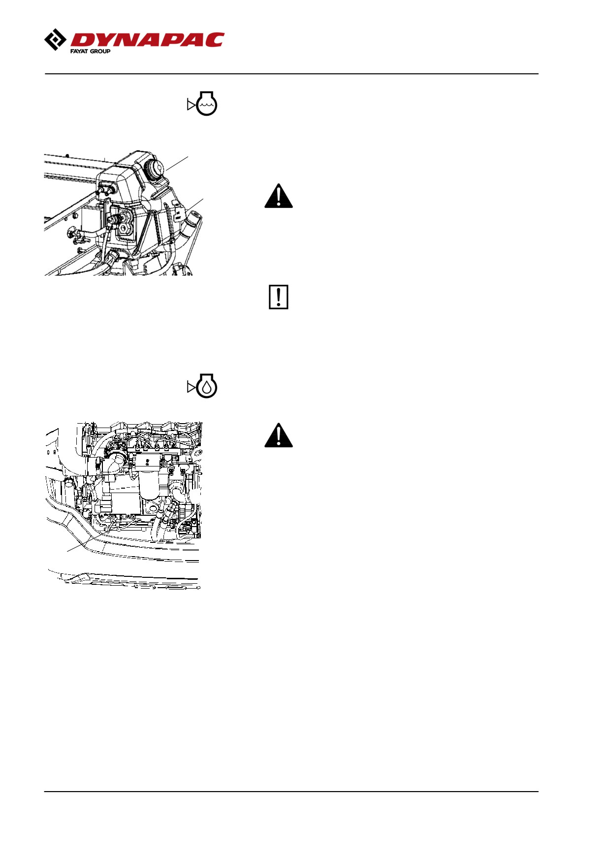
Coolant level - Check
Place the roller on a flat surface and check the level of
1
the coolant (2). Top up with coolant if the level is too
low.
Take great caution if the radiator cap must be
2
opened while the engine is hot. Wear protective
gloves and goggles.
Fill with a mixture of 50% water and 50% anti freeze.
See the lubrication specifications in these instructions
and in the engine manual.
Flush the system every other year and change
Fig. Expansion tank
the coolant. Make sure also that the air flow
1. Filler cap
through the cooler is unobstructed.
2. Level indicator
Diesel engine Check oil level
Take care not to touch any hot parts of the engine
or the radiator when removing the dipstick. Risk
for burns.
The dipstick is located beside the engine's oil and fuel
filter.
Pull up the dipstick (1) and check that the oil level is
between the upper and lower marks. For further
details, refer to the engine's instruction manual.
1
Fig. Engine compartment
1. Dipstick
2019-11-05
106
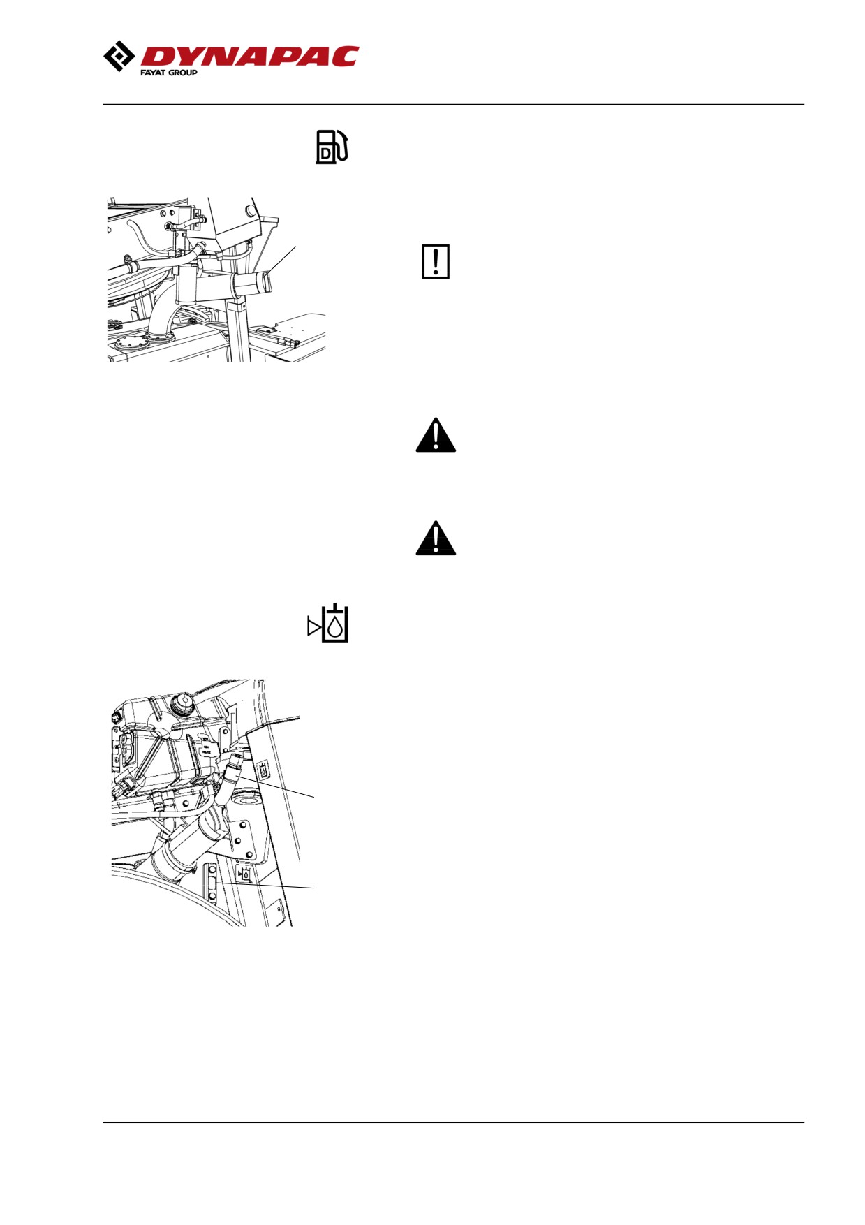
Maintenance, 10h
Fuel tank - Filling
Top up the fuel tank every day. Follow the engine
manufacturer's specifications for diesel fuel.
1
Tier 4i/Stage IIIB Cummins engines require the
use of Ultra Low Sulphur Diesel (ULSD) fuel,
which has a sulphur content of 15 ppm (parts per
million) or less. A higher sulphur content will
cause operating problems and put the useful life
of components at risk, which can lead to engine
trouble.
Fig. Fuel tank
1. Filler pipe
Stop the engine. Short-circuit (press) the filler gun
against a non-insulated part of the roller before
refuelling, and against the filler pipe (1) while
refuelling.
Never refuel while the engine is running. Do not
smoke and avoid spilling fuel.
Hydraulic reservoir - Check fluid level
Place the roller on a level surface and check that the
oil level in the sight glass (1) is between the max and
min markings.
Top up with the type of hydraulic fluid specified in the
lubricant specification, if the level is too low.
The volume between the min. and max. lines is
2
approx. 4 liters (4.2 qts).
1
Fig. Hydraulic reservoir
1. Sight glass
2. Filler pipe
2019-11-05
107
Maintenance, 10h
2019-11-05
108
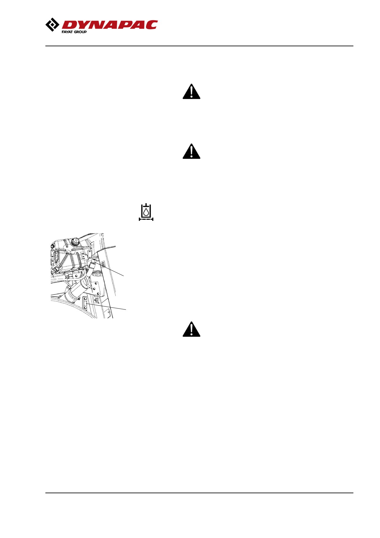
Maintenance, first 50h
Maintenance, first 50h
Park the roller on a level surface.
The engine must be switched off and the
parking brake activated when checking or
adjusting the roller, unless otherwise specified.
Ensure that there is good ventilation (air
extraction) if the engine is run indoors. Risk of
carbon monoxide poisoning.
Hydraulic filter - Replacement
Undo the filler cap/bleeder filter (2) on top of the
reservoir so that over-pressure inside the reservoir can
be eliminated.
Make sure that the bleeding filter (2) is not clogged, air
must have unobstructed passage through the cap in
2
both directions.
If passage in either direction is blocked, clean the filter
with a little diesel oil and blow through with
3
compressed air until the block is removed, or replace
the cap with a new one.
Wear protective goggles when working with
Fig. Hydraulic reservoir
compressed air.
2. Filler cap/Bleeding filter
3. Sight glass
2019-11-05
109