DYNAPAC Vibratory roller CA2500/2800/3500/4000. Instruction manual (2019) - page 2
Machine description
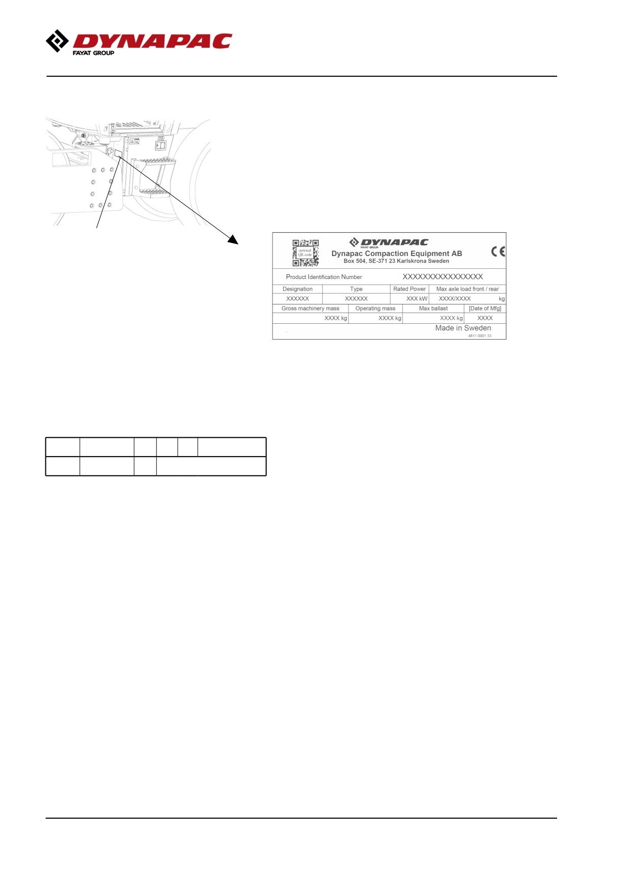
Machine plate
The machine type plate (1) is attached to the front left
side of the frame, beside the steering joint.
The plate specifies the manufacturer's name and
address, the type of machine, the PIN product
identification number (serial number), service weight,
engine power and year of manufacture. (If the
machine is delivered outside the EU there are no CE
markings, and on some machines the year of
manufacture may not be specified.)
1
Fig. Operator's platform
1. Machine plate
Please state the machine's PIN when ordering
spares.
Explanation of 17PIN serial number
100
00123
V
x
A
123456
A= Manufacturer
A
B
C
F
B= Family/Model
C= Check letter
F= Serial number
2019-11-05
30
Machine description
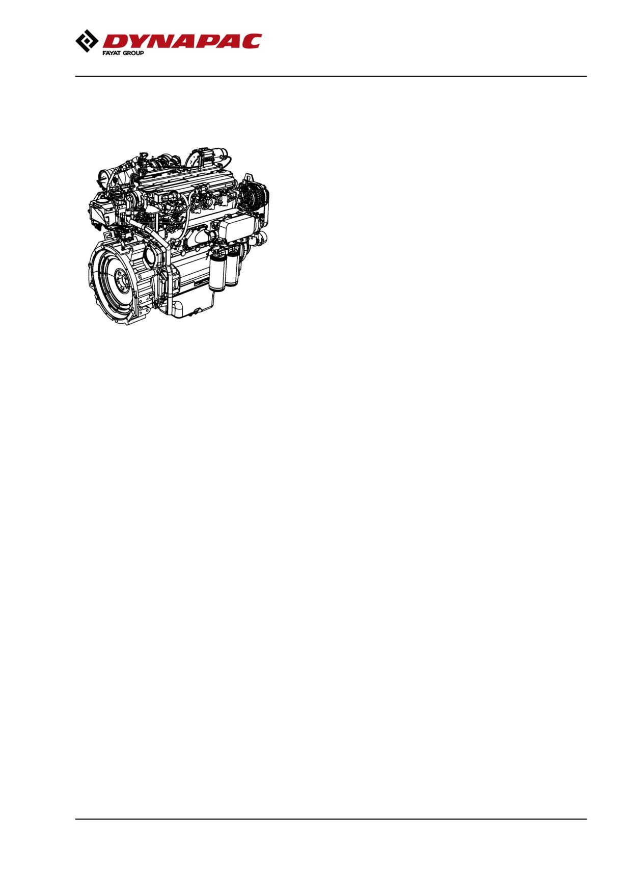
Engine plates
The engine type plates (1) are affixed to the top and
on the right side of the engine.
The plates specify the type of engine, serial number
and the engine specification.
Please specify the engine serial number when
ordering spares. Refer also to the engine manual.
On certain machines there may be an engine plate
along with the machine plate, if the original plate on
the engine is covered with extra
equipment/accessories.
2019-11-05
31
Machine description
Decals
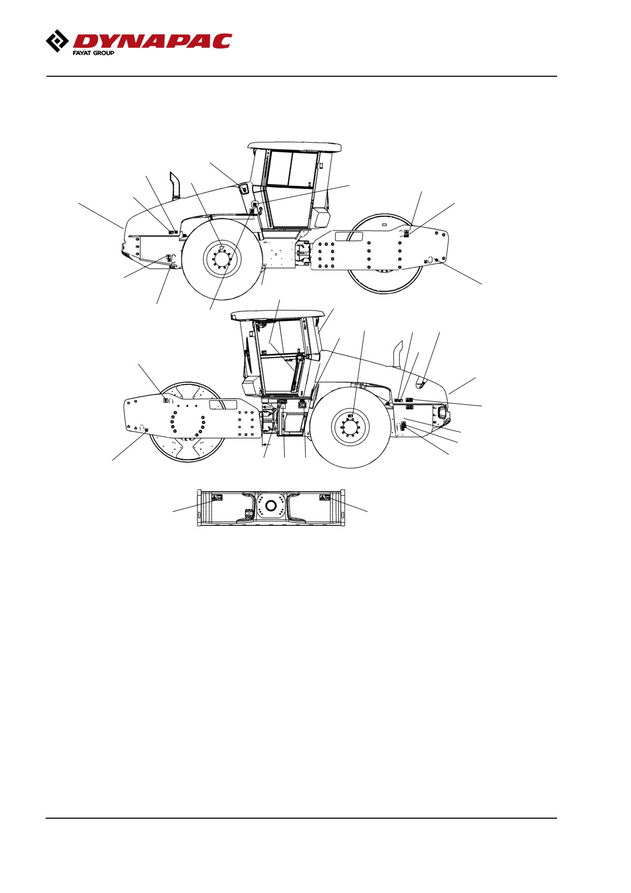
Location - decals
13
14
6
15,16
19
6
7
3
20
10
18
24
22
18
17,23
6
14
9
11
6
20
2
4
19
7
18
5
18
21
12
1
1
Fig. Location, decals and signs
1. Warning, Crush zone
4700903422
12. Master switch
4700904835
2. Warning, Rotating engine
4700903423
13. Coolant
4700388449
components
3. Warning, Hot surfaces
4700903424
14. Air pressure
4700385080
4. Warning, Brake release
4700904895
15. Hydraulic fluid level
4700272373
5. Warning, Instruction manual
4700903459
16. Hydraulic fluid
4700272372
Biological hydraulic fluid
4700792772
6. Warning, Ballasted tires
4700903985
17. Diesel fuel
4700991658*
4811000345**
7. Warning, Locking
4700908229
18. Fixing point
4700382751
4812125363
19. Hoisting plate
4700904870
9. Warning, Starting gas
4700791642
20. Lifting point
4700588176
10. Handbook compartment
4700903425
21. Sound power level
4700791273/76
11. Battery voltage
4700393959
22. Emergency exit
4700903590
23. Fuel with ultra low sulphur content
4811000344**
(IIIA/T3)
24. Draining fuel
4811000443
**
(IIIB/T4i)
2019-11-05
32
Machine description
Safety decals
Always make sure that all safety decals are completely
legible, and remove dirt or order new decals if they
have become illegible. Use the part number specified
on each decal.
4700903422
Warning - Crush zone, articulation/drum.
Maintain a safe distance from the crush zone.
4700903423
Warning - Rotating engine components.
Keep your hands at a safe distance.
4700903424
Warning - Hot surfaces in the engine compartment.
Keep your hands at a safe distance.
4700904895
Warning - Brake disengagement
Study the towing chapter before disengaging the
brakes.
Danger of being crushed.
4700903459
Warning - Instruction manual
The operator must read the safety, operation and
maintenance instructions before operating the
machine.
4700903985
Warning - Ballasted tire.
Read the instruction manual.
More information in section in Technical specifications.
2019-11-05
33
Machine description
4700908229
Warning - Risk of crushing
The articulation must be locked when lifting.
Read the instruction manual.
4812125363
Warning - Locking
The articulation must be locked during transport
and lifting,
but be open during operation.
Read the instruction manual.
4700903590
-Emergency exit
2019-11-05
34
Machine description
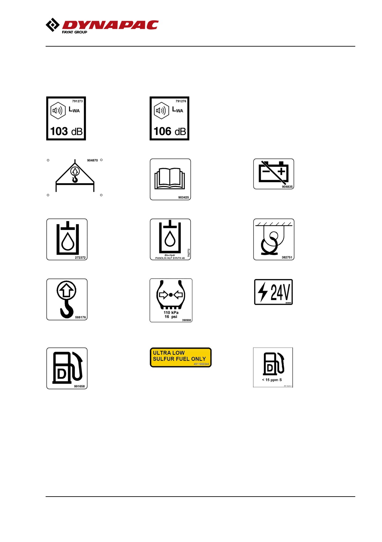
Info decals
Sound power level
Hoisting plate
Handbook compartment
Master switch
Hydraulic fluid
Biological hydraulic fluid
Securing point
Lifting point
Tire pressure
Battery voltage
Diesel fuel
Fuel with ultra low sulphur
(IIIB/T4i)
content
2019-11-05
35
Machine description
Instruments/Controls
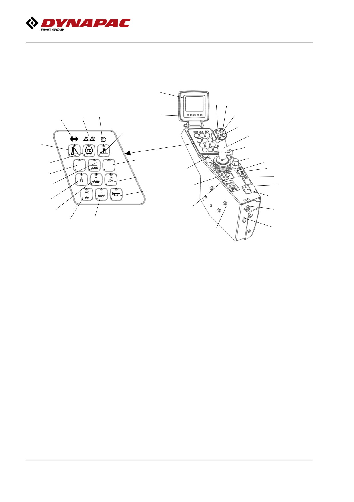
Control panel and controls
33
3
5
9
4
7
34
8
6
14
2
16
22
23
15
28
11
24
29
17
20
30
13
25
31
21
26
10
27
18
1
19
12
35
Fig. Control panel
36
1
Ignition switch
13
* Adjustable frequency/Seismic,
25
Parking brake
On/Off
2
Forward & Reverse lever
14
Working mode / Transport
26
Hazard lights
mode
3
* Strike-off blade, floating position 15
Reserve
27
Rotating beacon
4
Vibration on/off
16
Strike-off blade, On/Off
28
Reserve
5
17
Reserve
29
1)
Gear position switch, Dip
* Strike-off blade, Up
6
* Strike-off blade, Down
18
* Increase in frequency
30
N/A
7
Central warning indicator
19
* Reduction in frequency
31
*
Amplitude selector
8
* Direction indicators
20
* Working light
9
* Full beam indicator
21
Horn
33
Display
10
High amplitud
22
Emergency stop
34
Function buttons (5 pcs.)
11
* Auto Traction control
23
Speed limiter
35
Service socket
12
Auto vibration control (AVC)
24
Rpm switch, diesel engine
36
Height adjustment, control
panel
* Optional
1) Not valid with Auto Traction Control (11)
2019-11-05
36
Machine description
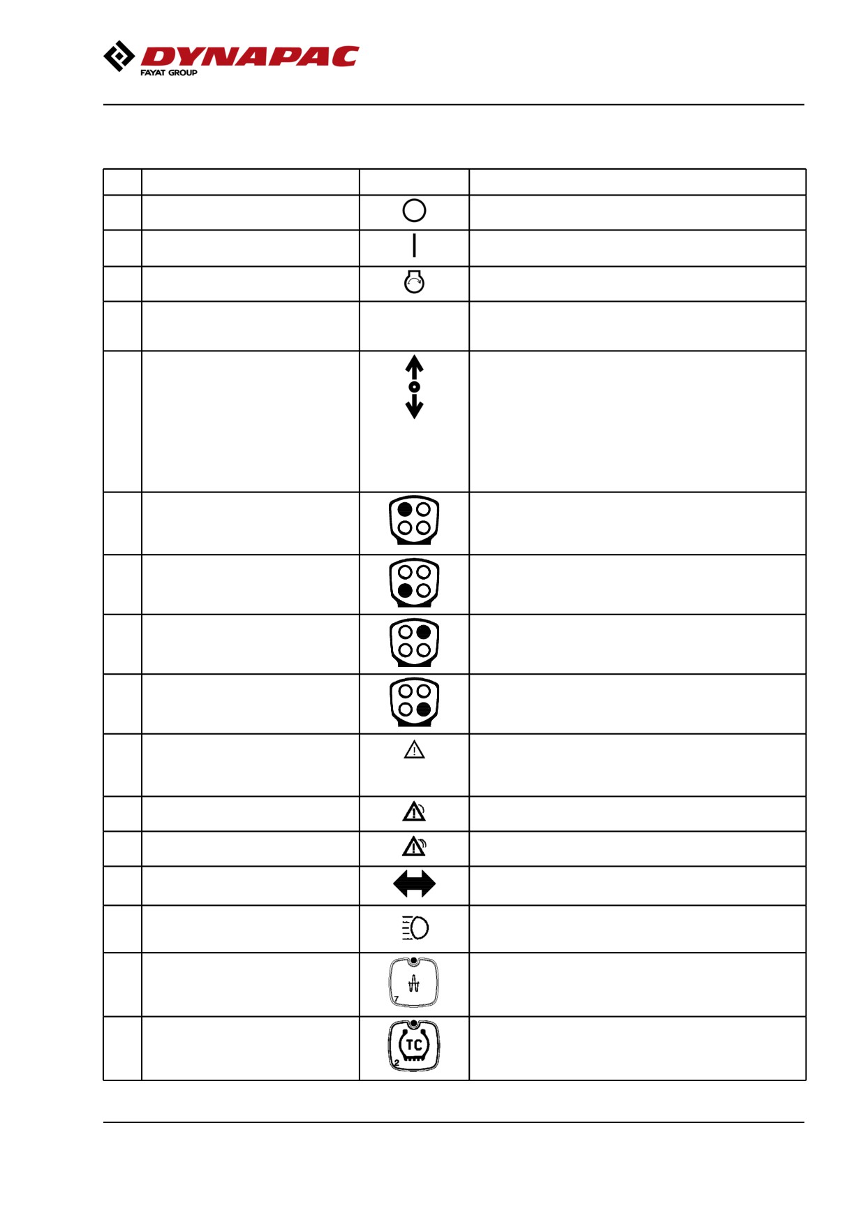
Function descriptions
No
Designation
Symbol
Function
1
Ignition key
The electric circuit is broken.
All instruments and electric controls are supplied with
power.
Starter motor activation.
To start: Turn ignition key to the right until the
display LIGHTS UP, and wait until the displayed
roller GOES OFF and changes to the status image.
2
Forward/Reverse lever
NB! When starting the machine, the lever must be in
neutral. The engine cannot be started if the
forward/reverse lever is in any other position.
The forward/reverse lever controls both the roller's
driving direction and speed. When the lever is moved
forward, the roller moves forward; when the lever is
move backward, the roller moves backward.
The roller's speed is proportional to the distance the
lever is from the neutral position. The further the lever
is from the neutral position, the higher the speed.
3
Strike-off blade, floating position
The float mode is activated by pressing and holding
(Optional)
the button for 2 seconds while the machine is in
Working mode (14) and Strike-off blade (16) is
activated.
4
Vibration on/off
First push will start vibrations, second push will stop
vibrations.
5
Strike-off blade, up (Optional)
Raises the strike-off blade when Strike-off blade (16) is
activated.
6
Strike-off blade, down (Optional)
Lowers the strike-off blade when Working mode (14)
and Strike-off blade (16) on the machine are activated.
7
Central warning indication
General fault indication. See the display (33) for
description of the fault.
For detailed information about the fault indication, see
the table "Warning indication - membrane panel".
Yellow warning light - "less serious fault"
Warning lights red - "serious fault"
8
Direction indicator (Optional)
Shows direction indicators activated (Activated via the
steering column switch).
9
Main beam indicator (Optional)
Shows main beam activated (Activated via the steering
column switch).
10
Amplitude selector, high amplitude
Activation produces high amplitude. (Low amplitude is
the basic mode if the button is not activated.)
11
Auto traction control, TC
If the machine is equipped with TC (Anti-spin), this is
(Anti-spin) (Optional)
activated when starting up. (TC can be disengaged).
The speed limiter (23) is used to set the maximum
speed at full deflection of the forward/reverse lever.
2019-11-05
37
Machine description
No
Designation
Symbol
Function
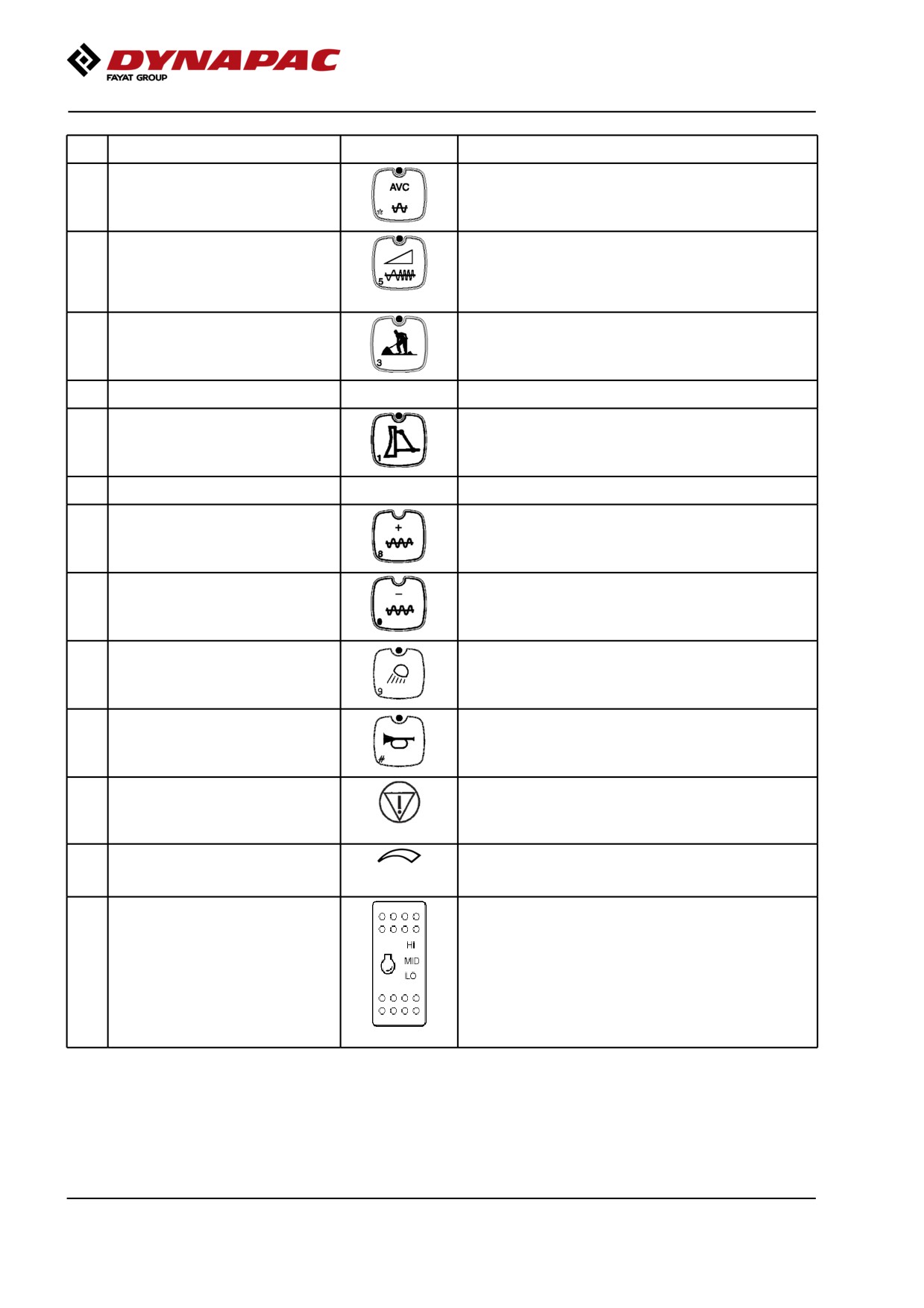
12
Automatic vibration control (AVC)
When activated, the vibration is switched on
automatically when the roller's speed is ≥ 1.8 km/h
(1.1 mph) and disengaged at a speed of 1.5 km/h (0.9
mph).
13
Adjustable frequency On/Off
Activates adjustable frequency, see also buttons 18
(Optional)
and 19.
Deactivated (LED off) produces fixed set vibration
frequencies for the machine. Seismic machine
frequency automatically be optimized at all times.
14
Working mode / Transport mode
Activates working mode, which makes it possible to
use vibration and lower the strike-off blade (optional).
The roller always starts in transport mode.
15
Reserve
16
Strike-off blade On/Off (Optional)
Activates the strike-off blade and its functions, also
requires working mode (14) to be activated.
17
Reserve
18
Frequency, increase (Optional)
Increases vibration frequency
19
Frequency, decrease (Optional)
Decreases vibration frequency
20
Working lights (Optional)
By activating the working lights will turn ON.
21
Horn
Press to sound the horn.
22
Emergency stop
Brakes the roller and switches off the engine. The
power supply goes off.
NB! When starting the machine, the emergency stop
must be inactive.
23
Speed limiter (Optional)
Limitation of the machine's max. speed (max.speed is
obtained with full deflection of the F/R lever). Set the
knob to the position for the desired max. speed.
24
Rpm switch, diesel engine
Three-position switch for idling (LO), intermediate
speed (MID) and working speed (HI).
NOTE:The lever must be in neutral (LO) when starting
the machine. The engine also runs at low speed when
stationary, more than approx. 10 seconds if the F&R
lever is in neutral.
If the F&R lever is moved out of neutral the speed will
increase to the set speed again. If the machine has a
fuel optimization system, MID is replaced by ECO (and
the switch is green).
2019-11-05
38
Machine description
No
Designation
Symbol
Function
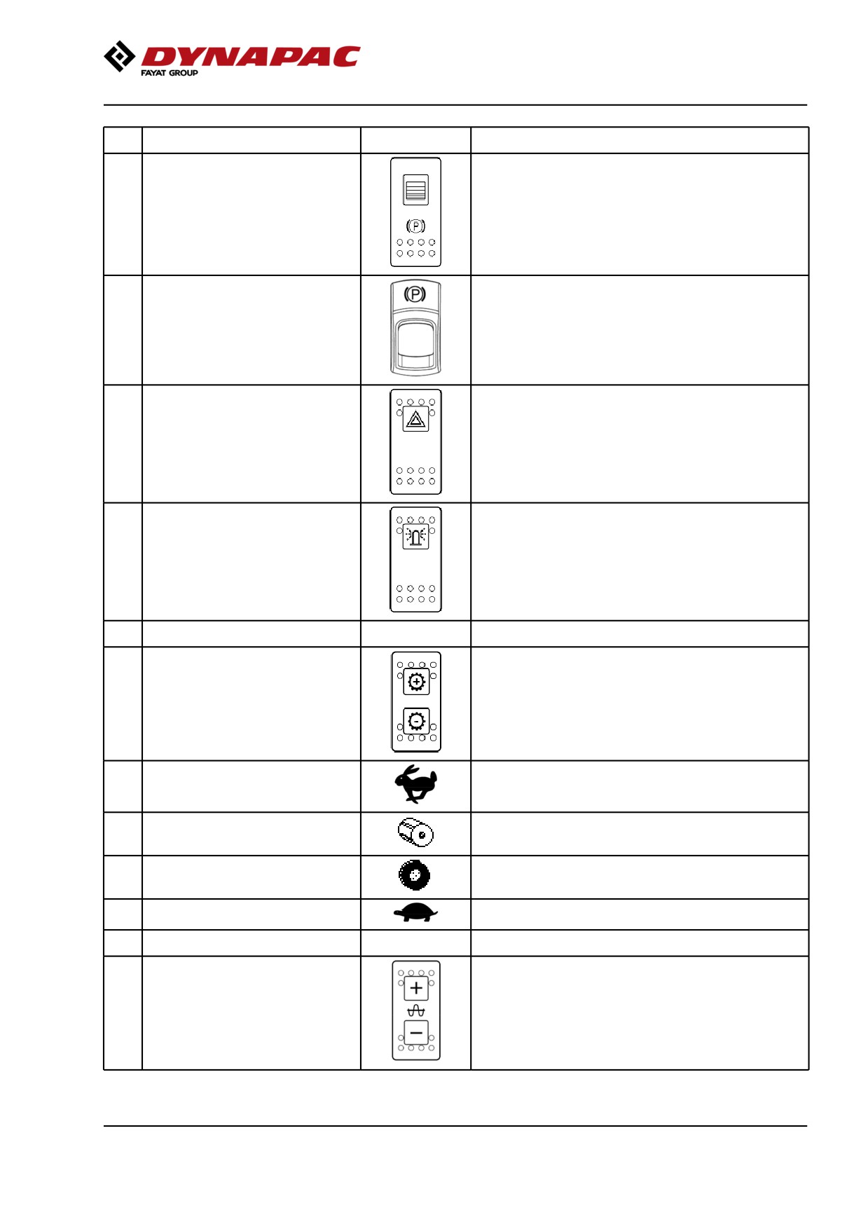
25
Parking brake
When pressed, the parking brake is activated.
To release the brakes, slide the red part back (towards
you) and change the position of the switch.
NOTE:When starting the machine, the parking brake
must be activated.
To activate the brakes, press the top of the switch to
change the position of the switch.
To release the brakes, press down the red part at the
same time as the switch and change the position of
the switch.
NOTE:When starting the machine, the parking brake
must be activated.
26
Hazard indicators (Optional)
Activate the hazard warning light by depressing the
button.
27
Rotating beacon (Optional)
Activate the rotating beacon by pressing the switch. (If
the machine has two rotating beacons, both are
activated)
28
Reserve
29
Gear position switch, Dip
Activates the four different gear positions. (1) Hare, (2)
Drum spin, (3) Wheelspin and (4) Tortoise. The current
gear position is shown in the display by means of the
following figures.
1: Transport mode
2: Used if the drum is slipping.
3: Used if the rear tires are slipping.
4: Working mode.
30
Reserve
31
Amplitude selector (DCO)
Only for machine equipped with "Compaction
Optimizer".
2019-11-05
39
Machine description
No
Designation
Symbol
Function
35
Service socket
Diagnostic socket.
Gateway is connected here to read the CAN-Open
system.
Warning indication - membrane panel (Keypad)
"Yellow" - Warning
-
The engine has an alarm in category yellow
(Alarm image shown in the display)
-
Communication with the display is interrupted
-
The fuel level is below <10%
-
Charging absent
"Red" - Warning
Flashes red continuously
-
The engine has an alarm in category red
(Alarm code shown in the display)
-
Communication with the engine is interrupted
-
The engine temperature is too high
-
Low oil pressure in the engine
-
The air filter is clogged
-
The hydraulic fluid temperature is too high
-
The hydraulic fluid filter is clogged
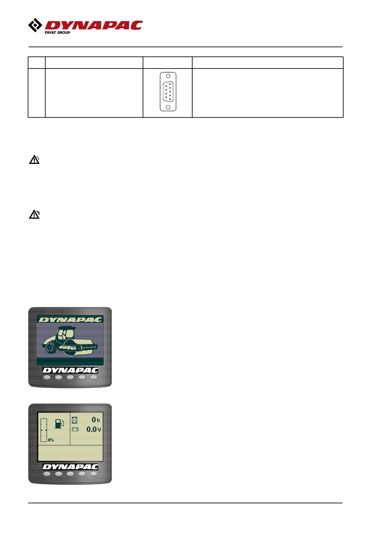
Display explanations
When the ignition key is activated to position I, a start
screen is visible in display. This is shown for a few
seconds and then switches over to the status screen.
Before activating the starter motor, wait until the start
image has changed to the status image (the machine
is performing a system check while the start image is
being displayed).
Fig. Start screen
The status image provides information on the fuel
level, machine hours and voltage level. The fuel level
is indicated as a percentage (%).
This screen is active until the Diesel engine is started
or an active screen choice is made via the function
buttons below the display.
Fig. Status screen
2019-11-05
40
Machine description
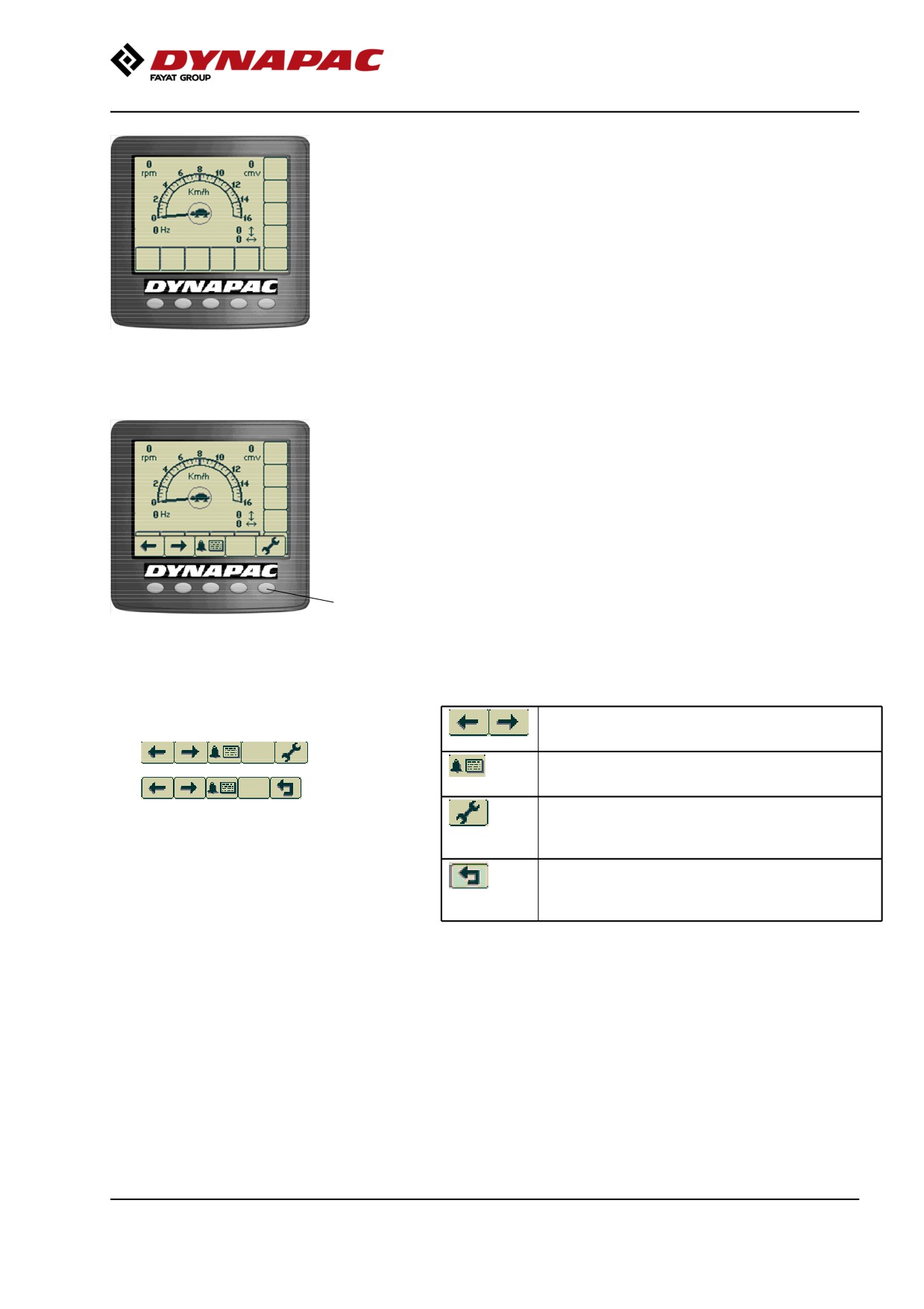
If the engine is started before any active screen choice
is made the display will switch over to main screen.
This screen gives an overview and is kept during work:
- The speed is shown in the middle of the display.
(km/h or mph)
Fig. Main screen/Working screen
- Engine speed, vibration frequency (optional), CMV
value for compaction meter (optional) and slope as a
% (optional) are shown in the corners.
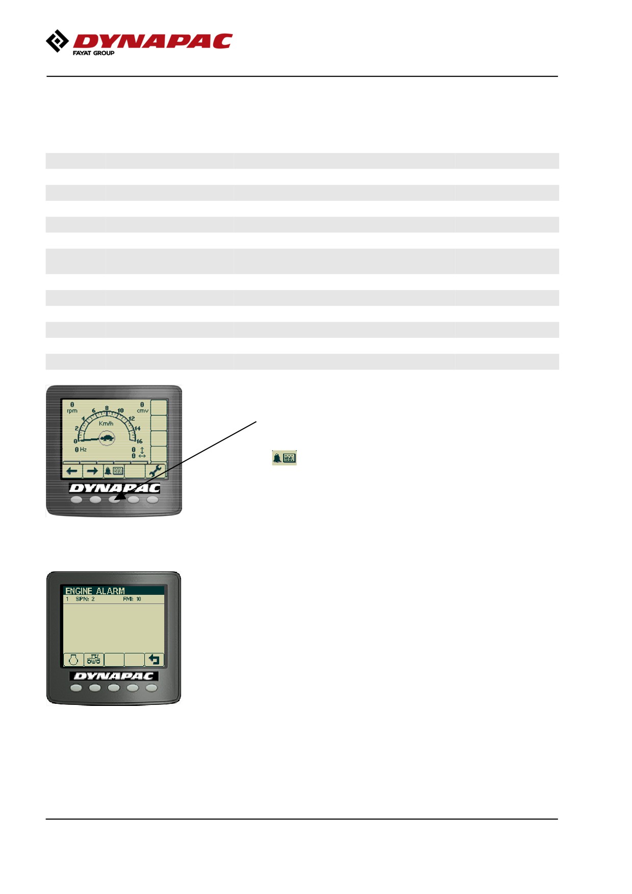
A menu field is shown by pressing one of the menu
select buttons. The field is visible for a short while, if
no selection is made the field fades out. Menu field will
appear again upon pressing either one of the selection
buttons (1).
1
Fig. Main screen/Working screen with
menu selection buttons (1)
Example of menu field.
Scroll/Selection buttons to choose
between available functions.
Alarm log button to display engine and
machine alarms.
Settings/Button select menu, which opens
the main menu. Settings can be changed
in the main menu.
Exit/Return button returns 1 step at once.
Pressing the button (approx. 2 sec.)
displays the main menu again.
2019-11-05
41
Machine description
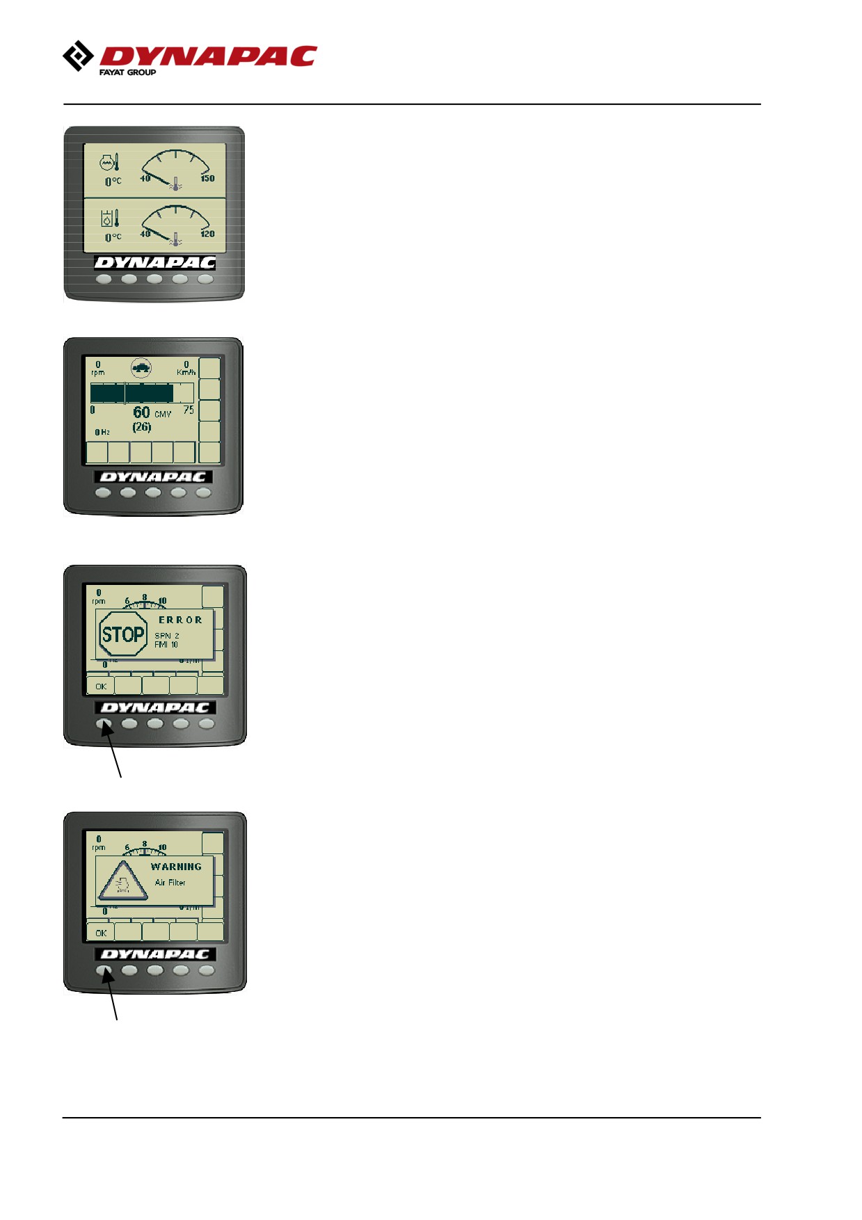
The temperature screen shows the temperature of the
engine (top of display) and hydraulic fluid (bottom of
display). The values are shown in Celsius or
Fahrenheit, depending on the choice of unit system.
Fig. Temperature screen
A display for the compaction value (CMV value) can
also be shown when the compaction meter (Option) is
installed on the machine. Further information on this
accessory is given in the Chapter "Operation".
Fig. Compaction meter display (CMV
display)
When an engine alarm is activated, the alarm is shown
on the display.
The engine alarm is sent out from the engine ECM,
which handles the monitoring of the engine functions.
The message, which consists of an SPN and FMI
code, can be interpreted via the engine supplier error
code list.
The alarm message shown is acknowledged by
pressing the "OK" button on the display.
When a machine alarm is activated the alarm is shown
on the display, plus a warning text that describes the
alarm.
The alarm message shown is acknowledged by
pressing the "OK" button on the display.
2019-11-05
42
Machine description
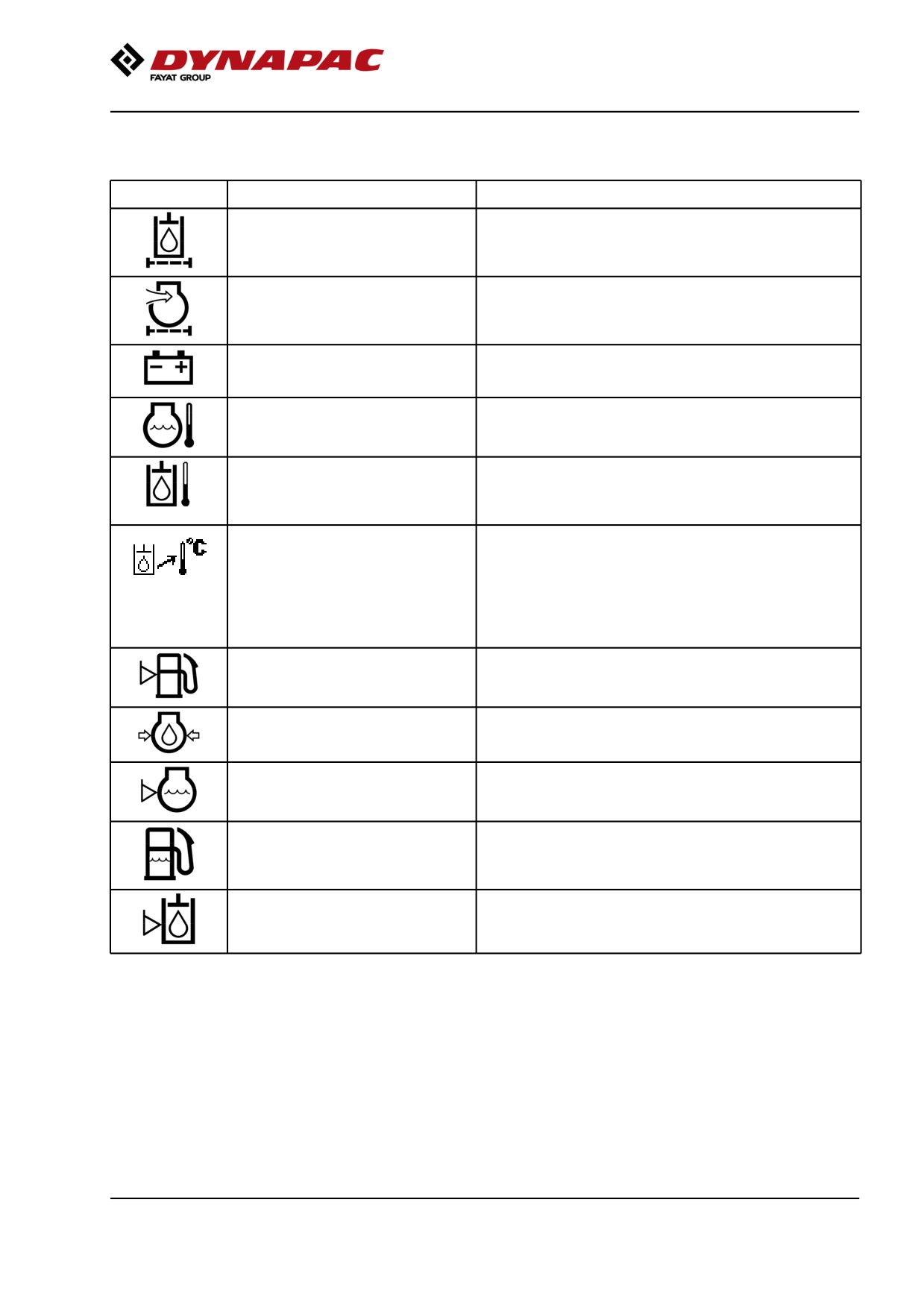
Machine alarm
Symbol
Designation
Function
Warning symbol, hydraulic fluid filter
If the symbol is shown when the diesel engine is running at
full speed, the hydraulic fluid filter must be changed.
Warning symbol, clogged air filter
If this symbol is shown when the engine is running at full
speed, the air filter must be checked/replaced.
Warning symbol, battery charging
If the symbol is shown when the engine is running, then
the alternator is not charging.
Switch off the engine and locate the fault.
Warning symbol, engine temperature
If this symbol is shown, the engine is too hot. Stop the
engine immediately and locate the fault.
Refer also to the engine manual.
Warning symbol, hydraulic fluid
This symbol is shown when the hydraulic fluid is too hot.
temperature
Do not drive the roller; allow the fluid to cool by running the
engine on idle, and then locate the fault.
Warning symbol, hydraulic fluid
If the symbol is displayed, the hydraulic oil is cold and the
temperature (coldl)
speed cannot be increased until the oil has reached 0° C
(32° F).
The maximum speed cannot be used between 0° C (32° F)
and + 5° C (41° F).
If the machine is moving at the same time as any of the
above limitations are exceeded, it may be necessary to
first go to neutral before vibration/speed can be activated.
Warning symbol, low fuel level
If this symbol is shown, there is less than 10% of the fuel
left.
Warning symbol, low oil pressure,
If this symbol is shown, the engine's oil pressure is too low.
diesel engine
Switch off the engine immediately.
Warning symbol, low coolant level
If this symbol is shown, fill with coolant/glycol and search
for leaks.
Warning symbol, water in the fuel
If this symbol is shown, the engine must be stopped and
the fuel pre-filter drained of water.
Warning symbol, low hydraulic fluid
If this symbol is shown, fill with hydraulic fluid to the correct
level
level and search for leaks.
2019-11-05
43
Machine description
Dynapac Sub System (DSS)
DSS
Description
Note
code
1
Speed sensor, front
Optional
2
Speed sensor, rear
3
Inclination sensor
Optional
4
DCM
Optional
5
IO-Card
6
Cooling fan speed sensor
7
Vibration frequency meter
Supervision only active if Adjustable frequency or Optional
ECO available.
8
Power group 1
see Fuse 3
9
Power group 2
see Fuse 4
10
Power group 3
see Fuse 5
11
Power group 4
see Fuse 6
12
DCO
Com Error
Optional
13
Hydraulic temp sensor
Sensor data out of range
Alarms received are logged and can be seen by
selecting Display alarms.
Inactive faults disappear from the log when you restart
the ignition.
Selection of Display alarms.
"ENGINE ALARM"
Logged engine alarms.
Stored in the engine ECU.
2019-11-05
44
Machine description
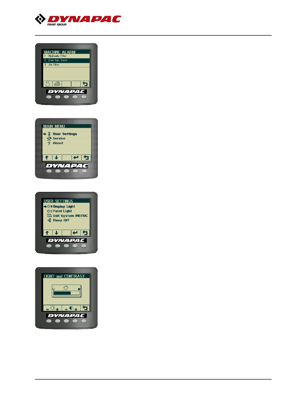
"MACHINE ALARM"
Logged machine alarms. These alarms come from the
other systems on the machine.
"MAIN MENU"
In the main menu it is also possible to change some
user and machine settings, access the service menu
for calibration purposes (special service personnel
only, requires pin code), and to see the version of
installed software.
"USER SETTINGS"
Users can change the light settings, choose between
the Metric or Imperial system, and set warning sounds
On/Off.
Adjustment of the light and contrast settings on the
display, including brightness of the panel light.
2019-11-05
45
Machine description
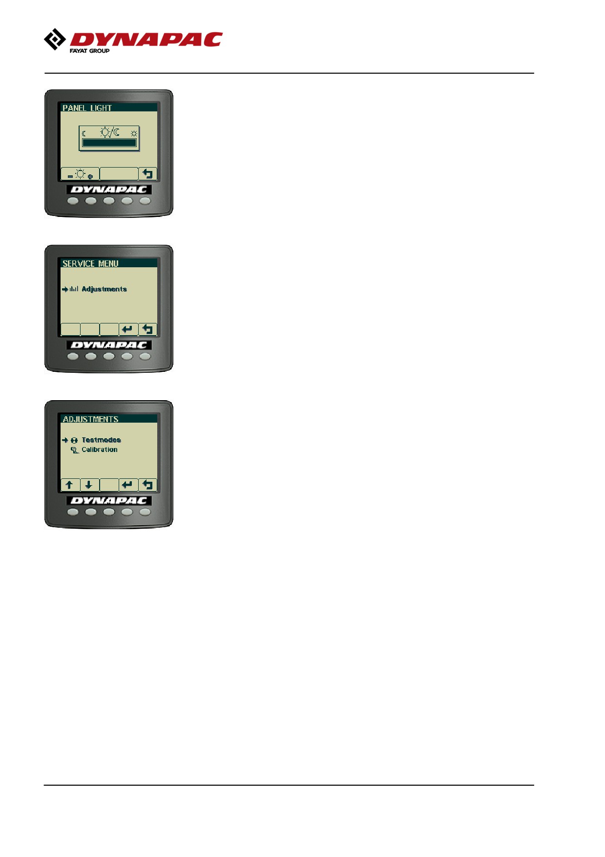
"SERVICE MENU"
The service menu is also accessible via the main
menu for adjustments.
"ADJUSTMENTS"
"TESTMODES" - Installation personnel only, requires
pin code.
2019-11-05
46
Machine description
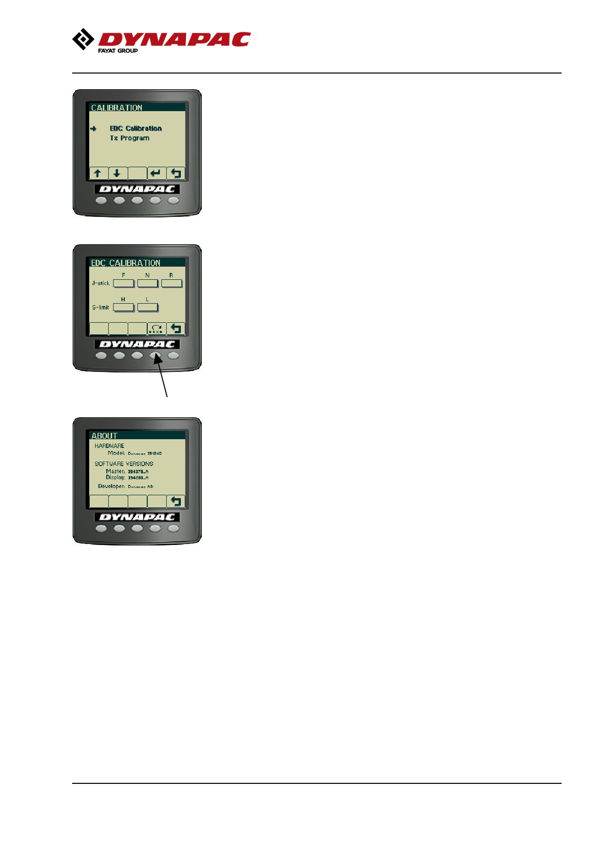
"CALIBRATION" - service personnel only, requires
password.
"EDC Calibration" used to calibrate the joystick and
speed potentiometer.
"TX Program" only used to change software in the
display and requires special equipment and know-how.
"EDC CALIBRATION"
To calibrate, move the joystick fully forward (F) and
press in both black buttons on the top of the joystick.
(See also manual W3025)
Continue in the same way with the other positions for
the joystick (N), (R) and the speed potentiometer.
Press the disk button to save the values.
"ABOUT"
It is also possible to see the version of the installed
software.
2019-11-05
47
Machine description
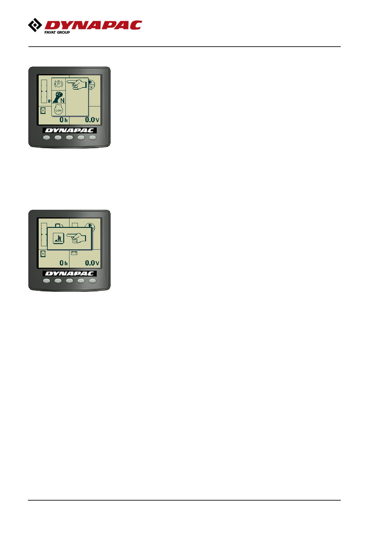
Operator help when starting
When trying to start the machine without having set
one, two or three of the conditions required to start
machine, the missing conditions are shown in the
display.
The missing conditions must be set before it is
possible to start the machine.
Conditions that must be set:
- Activated P-brake
- Selector lever in neutral
- Speed selector for diesel engine in low (Low = idling)
(not all models)
Operator help Workmode
When attempting to activate
- Vibration
- Strike-off blade (Optional)
with the machine in Transport mode the display will
show "Workmode" for a few seconds.
To activate the above functions it is necessary to
make sure that the machine's Workmode is activated.
2019-11-05
48
Machine description
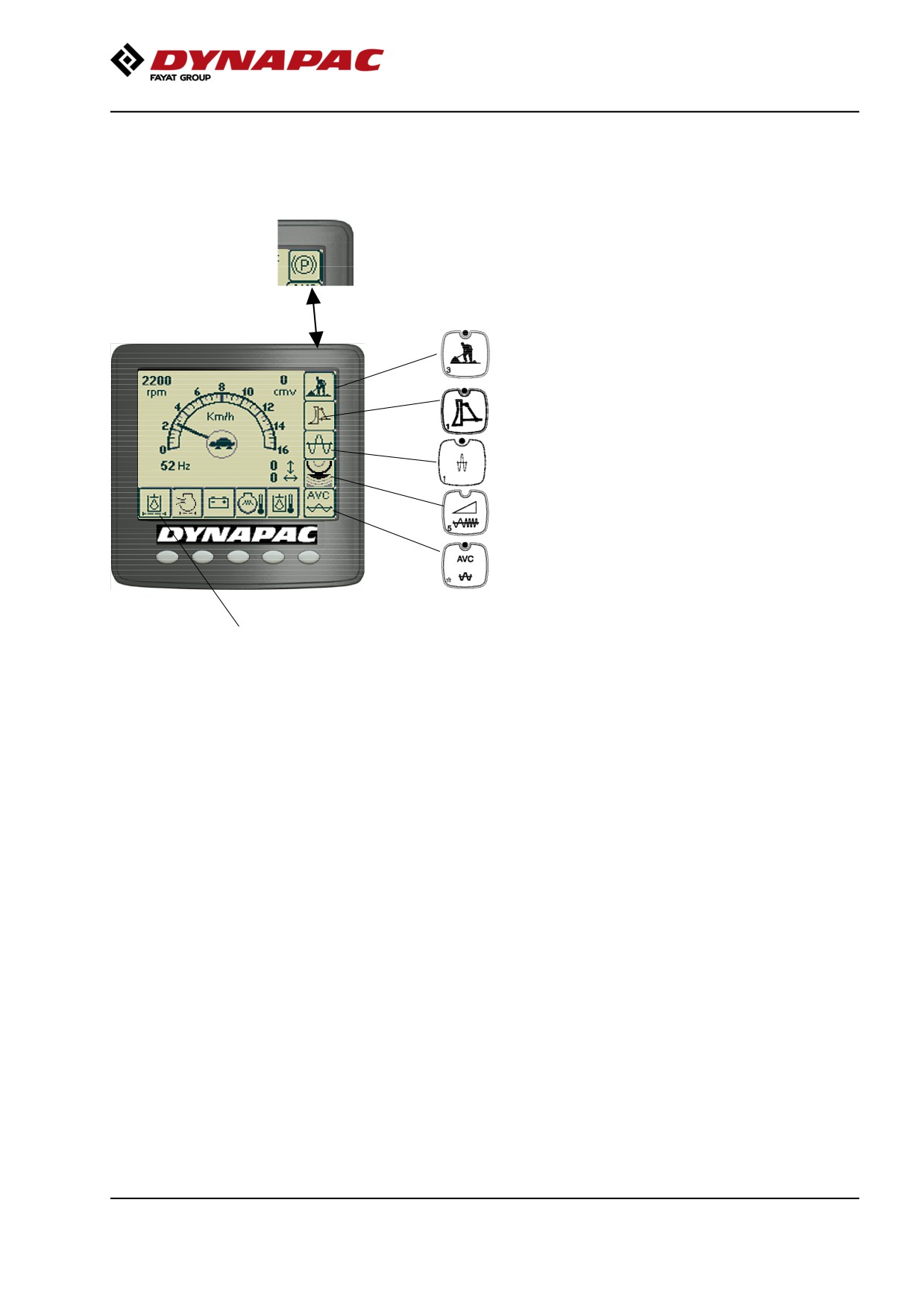
Display when activating choice via the button
set.
The parking symbol is shown when the parking brake is
activated.
= Vibration is enabled in the operating position.
= Strike-off blade
= High amplitude/Low amplitude
= Seismic active (LED off)
= Automatic vibration control. If the function is
activated via the red button on the control
lever, an image of a sine curve appears and
vibration is activated when the control lever is
moved out of neutral.
= Display of alarm, see table for information.
2019-11-05
49
Machine description
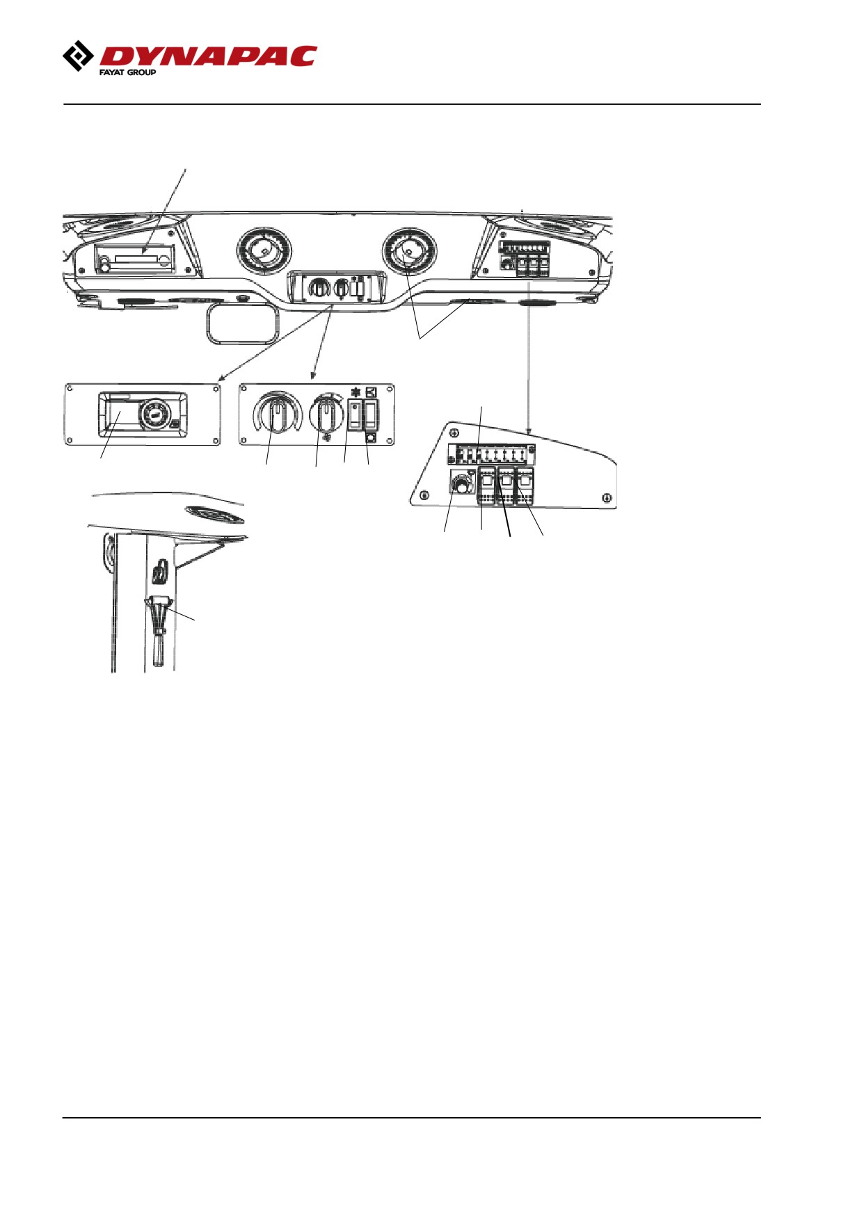
Instruments and controls, cab
Radio/CD
Fig. Cab roof, front
14
ACC
Heater/AC
8
10
1
2
3
4
9
5
6
7
15
Fig. Right rear cab post
15. Hammer for emergency exit
2019-11-05
50
Machine description
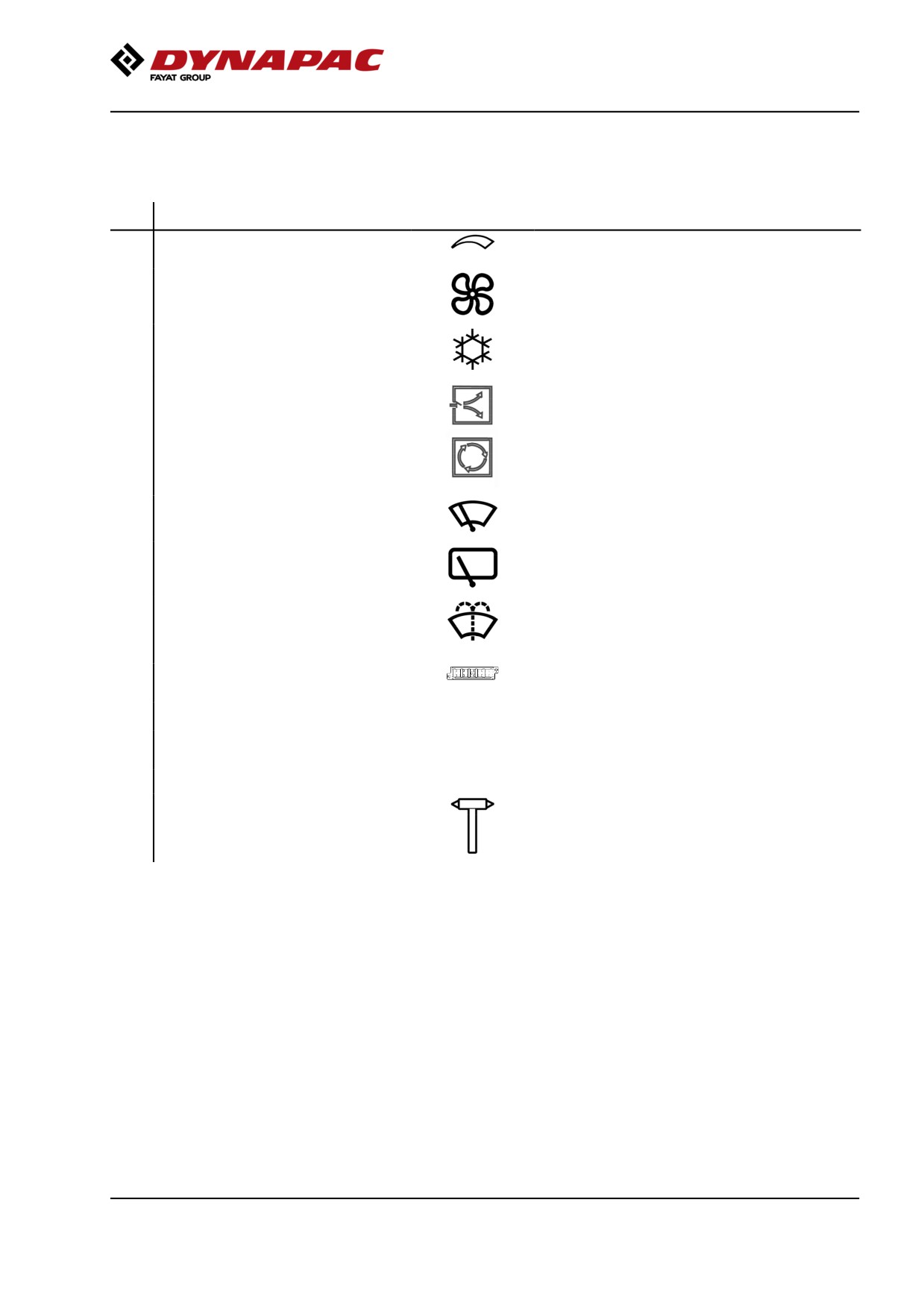
Function description of instruments and
controls in the cab
No
Designation
Symbol
Function
1
Heater control
Turn to the right to increase heating.
Turn to the left to reduce heating.
2
Ventilation fan, switch
In the left position, the fan is off.
Turning the knob to the right increases the
volume of air entering the cab.
3
Air conditioning, switch
Starts and stops the air conditioning.
4
Cab air recirculation, switch
Pressing the top opens the air damper so that
fresh air comes into the cab.
Pressing the bottom closes the damper so that
the air recirculates inside the cab.
5
Front wiper, switch
Press to operate the front screen wiper.
6
Rear wiper, switch
Press to operate the rear screen wiper.
7
Front and rear window screen
Press the upper edge to activate the front screen
washers, switch
washers.
Press the lower edge to activate the rear screen
washers.
8
Fuse box
Contains fuses for the electrical system in the
cab.
9
Front wiper, intermittent
Intermittent function for front wiper.
10
Automatic Climate Control (ACC)
Automatic control of the air conditioning.
(micro ECC)
14
Defroster nozzle
Turn the nozzle to direct the flow of air.
15
Hammer for emergency exit
To escape from the cab in an emergency,
release the hammer and break the opening
windows on the right-hand side.
2019-11-05
51
Machine description
Using the cab controls
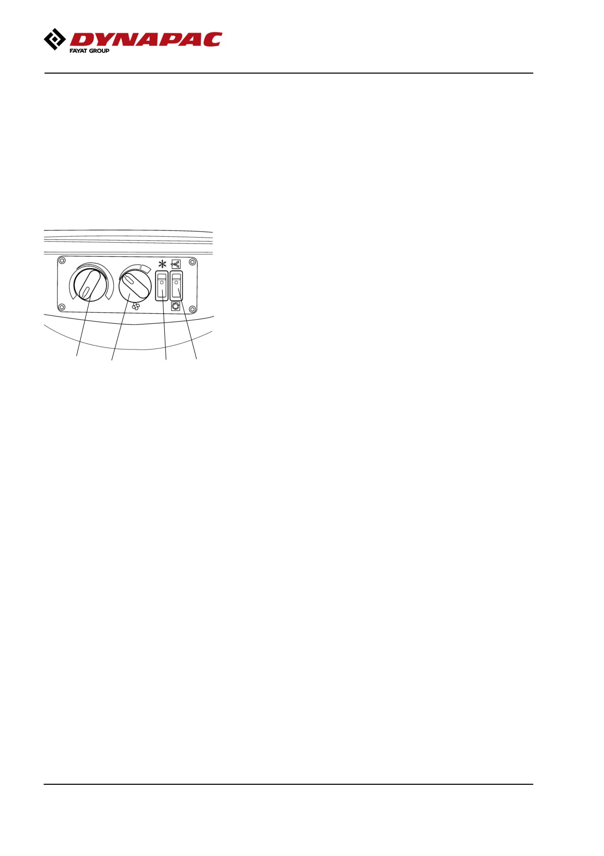
Defroster
To quickly remove ice or mist, make sure that only the
front and rear air nozzles are open.
Turn the heater and fan dial (1 and 2) to max.
Adjust the nozzle so that it blows on the window to be
de-iced, or to remove mist.
Heat
If the cab is cold, open the lower nozzle on the front
columns and the middle nozzles just over the controls
for the heater and fan.
Turn to max heat and max fan speed.
When the required temperature has been reached,
open the other nozzles and if necessary turn down the
heat and fan speed.
1
2
3
4
AC
AC/ACC
NOTE: When using AC/ACC all the windows must be
closed for the system to work efficiently.
To quickly reduce the temperature in the cab, adjust
the following settings on the control panel.
Turn on AC (3) and set the fresh air (4) in the lower
position to switch off the fresh air valve.
Set the heater control (1) to minimum and turn up the
fan speed (2). Keep only the front middle nozzles in
the ceiling open.
When the temperature has dropped to a comfortable
level, adjust the required temperature on the heater
control (1) and reduce the fan speed (2).
Now open the remaining nozzles in the roof to achieve
a comfortable temperature in the cab.
Reset the fresh air button (4) to the upper position for
fresh air.
2019-11-05
52
Machine description
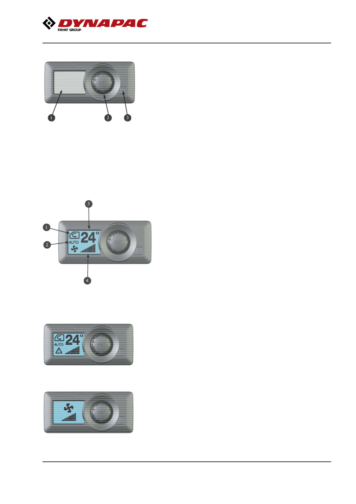
ACC - Control panel
1. LCD Display
During normal operation, the set-point temperature,
blower speed, operation mode and fresh/re-circulated
air selection are displayed.
2. SET / SELECT Button
Under normal operation button is used for selecting
between modes.
(Also used in Test / diagnostics mode for different
choices)
3. Power Button
Device ON/OFF.
Main display screen
1. Air mix control
The air mix can be set to full fresh air or full
re-circulated air.
2. Mode
Displays the mode, "Automatic", "Heat", "Cool" and
"Defrost"
3. Temperature Set-point
Displays current inside set-point temperature.
4. Blower speed
Displays current blower speed setting.
ACC - Operation menus
Main screen
When the unit is turned on, the main screen will
appear. Current set-point temperature, climat control
mode, air-circulation and blower speed are displayed.
A small warning icon appears if there is something
wrong with the system.
Blower speed settings:
Press SET / SELECT button until the blower icon
appears, then turn clockwise to increase blower speed
and counterclockwise to decrease blower speed with
5% increments.
The blower speed can not be adjusted in defrost mode
(Defrost).
2019-11-05
53
Machine description
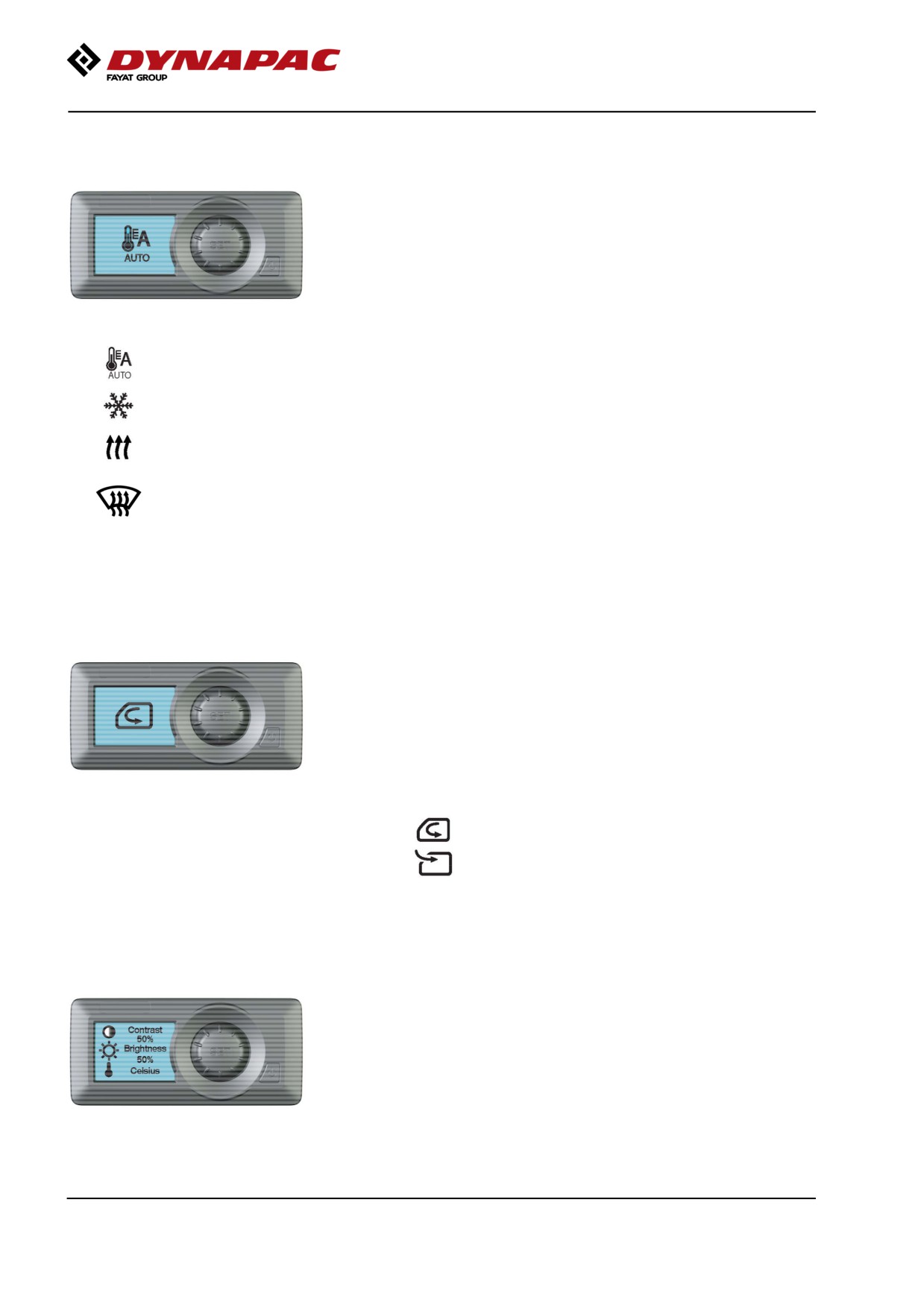
Climate Control mode settings:
Press SET / SELECT button until the climate control
mode icon appears, and then turn the button until the
required mode is displayed.
AUTO
The system runs automatically to keep the temperature that is
selected (set-point temperature).
Cool
A / C compressor is running to cool the interior temperature.
Heating valve is turned off while cooling off ("Cool") is selected.
Heat
Interior temperature warms up with the electronic heater valve.
A / C compressor is turned off while warming ("Heat") is
selected
Defrost
When defrosting ("Defrost") is activated, the A / C compressor
is turned on, the blower is turned on full speed and the heater
valve is fully open.
Air circulation setting:
Press the SET button until the air circulation mode
icon appears.
Turn the knob clockwise to fully recirculated air
or counterclockwise full fresh air.
Display settings:
To adjust the display settings and the temperature
scale, press the SET button until the display settings
screen appears, then turn the SET button clockwise or
counterclockwise to adjust the settings.
2019-11-05
54
Machine description
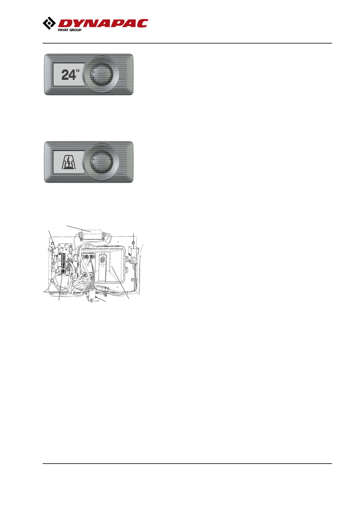
Turning HVAC system OFF:
In the main screen, press the Power button to turn off
the HVAC system. When the system is turned off, the
backlight will turn off and the interior temperature will
be displayed on the screen.
To turn off the HVAC system from Defrost mode,
press the Power button until the HVAC system returns
to the AUTO mode, then press the Power button again
to turn off the HVAC unit.
Diesel Heat mode (if diesel heater is installed):
When a Diesel heat mode signal is received, the
backlight will be turned off, the blower will run at 15%,
the heater valve will be fully opened and the air
circulation will switch to fresh air until the after coil
temperature is above 20 º C (78 º F). When the after
coil temperature is above 20 º C (78 º F), the blower
will run at a preset speed. No other function is allowed.
Electrical system
4
3
5
The machine's main switchbox (1) is located on the
rear left of the operator's platform. There is a plastic
cover over the distribution box and fuses.
On the plastic cover there is a 24V socket (X96) and a
12V socket (X98)(optional).
6
2
1
Fig. Main switchbox
1. Control unit (ECU)(A7)
2. Fuse card (A6)
3. Main relay (K2)
4. Power supply (A10), compaction
meter(DCM) (Optional)
5. Power converter 24/12V DC (T1)
6. Tilt sensor (B14) (Optional)
2019-11-05
55
Machine description
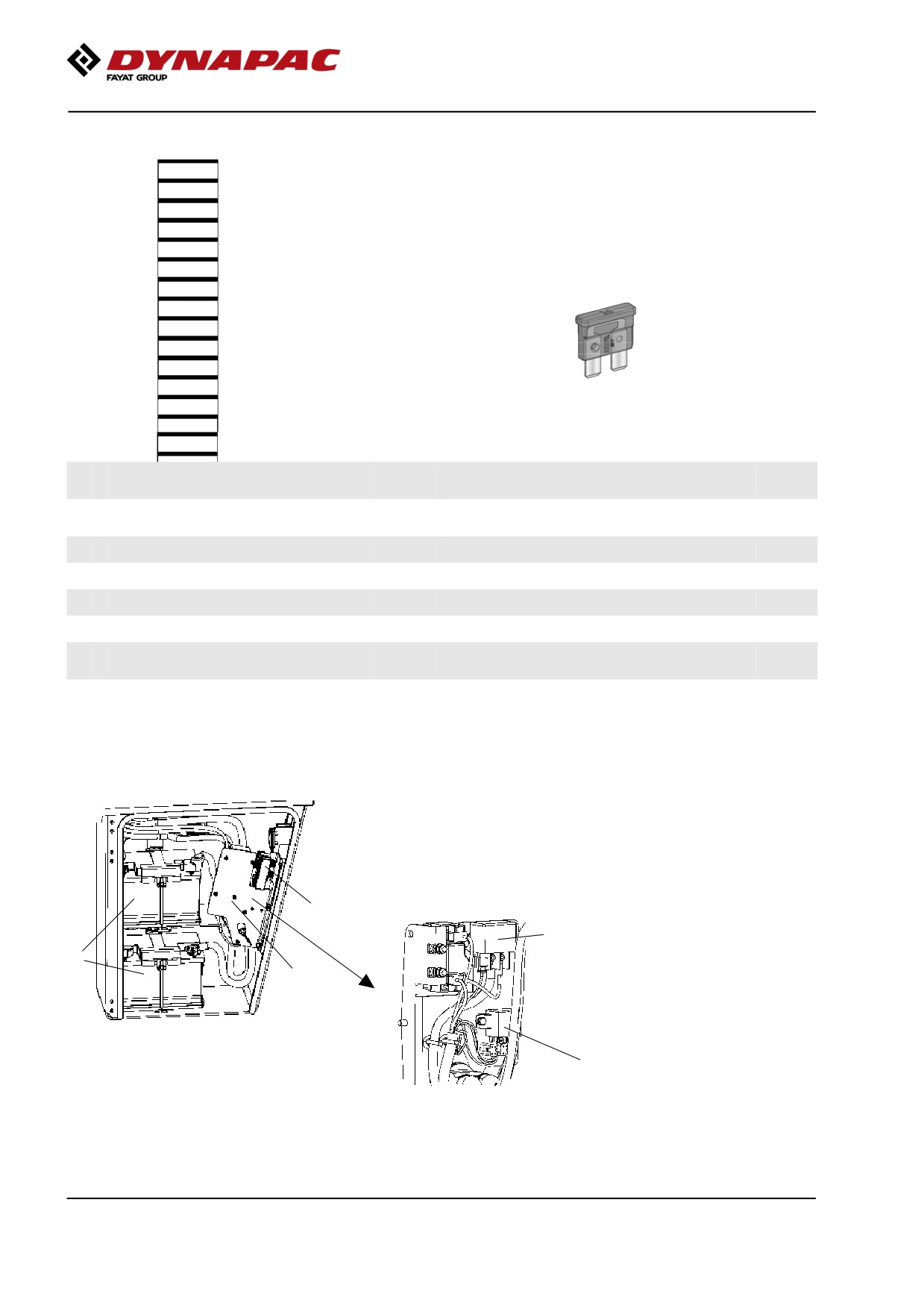
Fuses in the main switchbox (Cummins)
1
2
3
The figure shows the position of the fuses.
4
5
6
The table below gives fuse amperage and function. All
7
fuses are flat pin fuses.
8
9
10
11
12
13
14
15
1.
Main relay, 24V outlet engine
10A
9.
Reserve
compartment
2.
ECU, Outlet boot loading, I/O board,
5A
10.
Reserve
display
3.
ECU PWR1, Speed sensor
10A
11.
12V outlet, Radio/CD
10A
4.
ECU PWR2, Forward/Reverse lever
10A
12.
GPS, DCM, DCO, tilt sensor
10A
5.
ECU PWR 3
20A
13.
Reserve
6.
ECU PWR 4
20A
14.
DCA
10A
7.
24V outlet operator's station,
10A
15.
Indicator relay
7.5A
Tachograph
8.
Hydraulic/Fuel sensor, Engine
10A
16.
Driving lights
10A
Fuses at master switch (Cummins)
The fuse box (1) is located inside the cover by the
steps on the left-hand side of the roller.
This is also where the batteries (2) are, and the starter
relay (4) and preheating relay (5) are placed behind
the battery disconnector plate (3).
1
5
2
4. Starter relay, 50A
3
5. Preheating relay, 120A
Fig. Cover, left side
1. Fuse box
4
2. Batteries (x2)
3. Battery disconnector plate
2019-11-05
56
Machine description
Fuse box at master switch (Cummins)
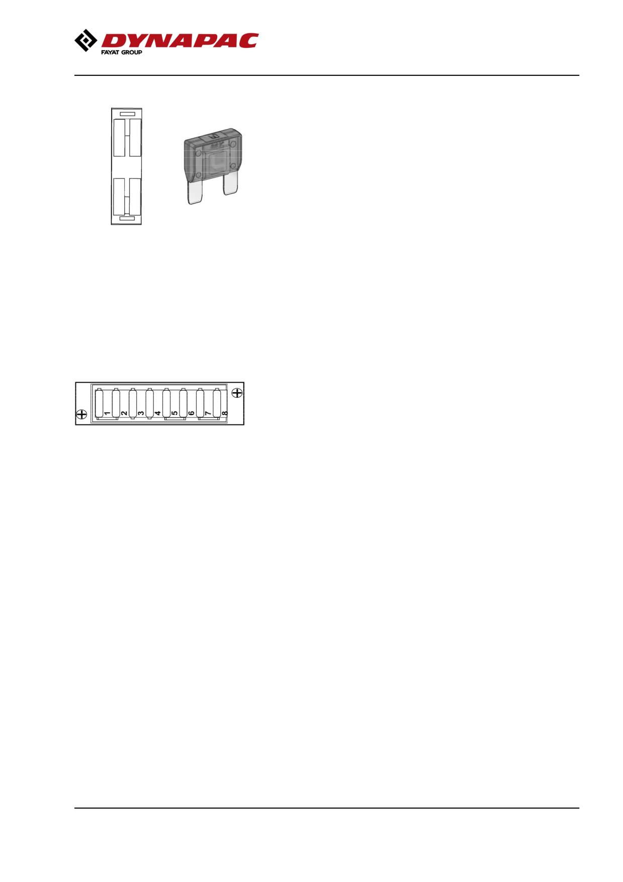
1
2
The figure shows the position of the fuses.
The amperage and function of the fuses are shown
below. All fuses are flat pin fuses.
3
4
1.
Main fuse
50A
2.
Cab
30A
3.
Diesel engine ECU
30A
(IIIA/T3)
Fig. Fuse box, battery disconnector
60A
(IIIB/T4i)
switch
4.
Grid heater
40A
Fuses in cab
The electrical system in the cab has a separate fuse
box located on the front right side of the cab roof.
The figure shows fuse amperage and function.
Fig. Cab roof fuse box (F7)
All fuses are flat pin fuses.
1. Interior lighting
10A
2. Windscreen wiper/washers
10A
3. Cab fan
15A
4. Reserve
5. Reserve
6. Reserve
7. Dyn@lyzer
7.5A
8. Reserve
2019-11-05
57
Machine description
2019-11-05
58
Operation
Operation
Before starting
Master switch - Switching on
Remember to carry out daily maintenance. Refer to
the maintenance instructions.
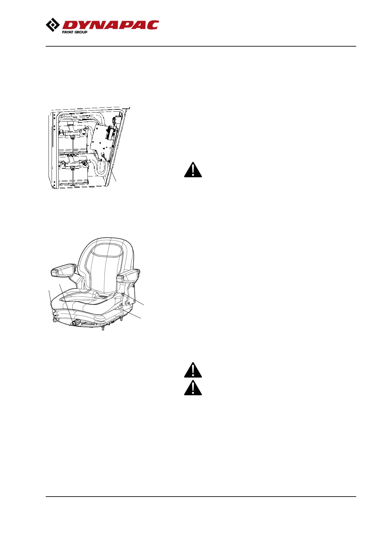
The battery disconnector switch is located inside the
cover by the steps on the left-hand side of the roller.
Turn the key (1) to the On position. The roller is now
supplied with power.
The cover must be unlocked when operating, so
that the battery can be quickly disconnected if
necessary.
1
Fig. Cover, left side
1. Battery disconnector switch
Operator's seat - Adjustment
Adjust the operator’s seat so that the position is
comfortable and so that the controls are within easy
reach.
2
1
The seat can be adjusted as follows.
4
- Length adjustment (1)
3
- Weight adjustment (2)
Fig. Operator's seat
- Back support angle (3)
1. Lock pack- Length adjustment
2. Weight adjustment
3. Back support angle
4. Seat belt
Always make sure that the seat is secure before
beginning operation.
Do not forget to use the seatbelt (4).
2019-11-05
59
Operation
Belt reminder
The machine can be equipped with seat belt with belt
reminder.
Unless the seat belt is used, a warning image appear
in the display and a warning buzzer sounds to alert the
driver to use the seat belt.
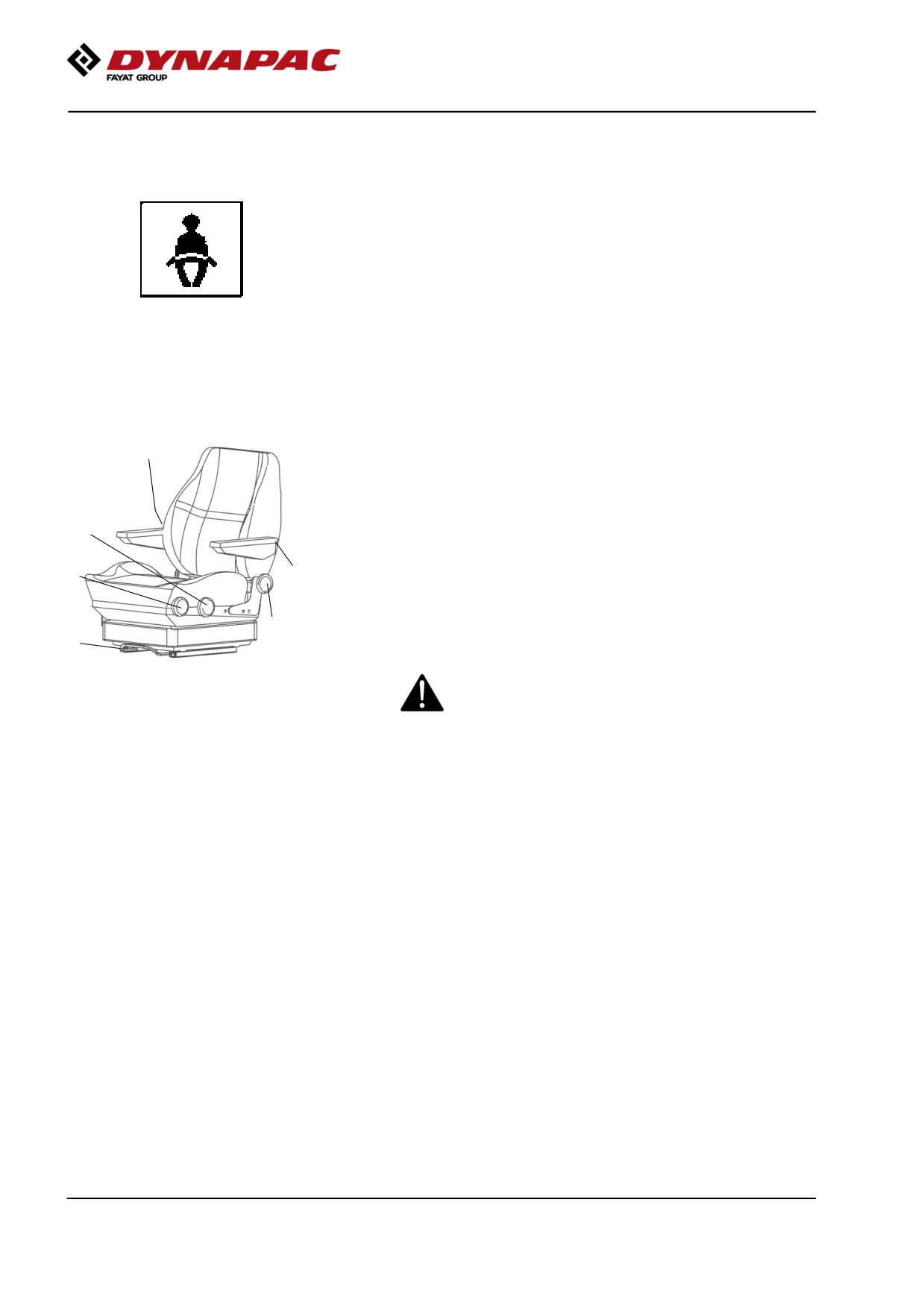
Operator's seat, comfort - Adjustments
6
Adjust the operator's seat so that the position is
comfortable and so that the controls are within easy
reach.
3
The seat can be adjusted as follows:
- Length adjustment (1)
- Height adjustment (2)
2
5
- Seat-cushion inclination (3)
- Backrest inclination (4)
- Armrest inclination (5)
4
- Lumbar support adjustment (6)
1
Fig. Operator’s seat
Always ensure that the seat is locked in position
1. Lever - length adjustment
before operating the roller.
2. Wheel - height adjustment
3. Wheel - seat cushion inclination
4. Wheel - backrest inclination
5. Wheel - armrest inclination
6. Wheel - lumbar support adjustment
2019-11-05
60
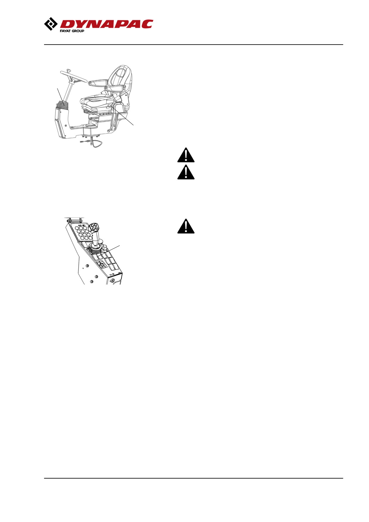
Operation
Control panel, adjustments
The control unit has two adjustment options, rotation
and steering column angle.
2
For rotation, lift the lever (1).
Ensure that the control unit locks in position before
operating the machine.
Release locking lever (2) to adjust the steering column
angle. Lock the steering column in the new position.
1
To adjust the operator's seat, see the section for
basic/comfort seat.
Fig. Operator's station
Adjust all settings when the machine is stationary.
1. Locking lever - rotation
2. Locking lever - steering column
angle
Always ensure that the seat is in locked position
before operating the roller.
Parking brake
Ensure that the parking brake (1) is definitely
switched on.
1
Brake is always activated in Neutral position.
(automatic 1.5 sec.)
Fig. Control panel
The parking brake must be activated to start the
1. Parking brake
machine!
2019-11-05
61
Operation
Display - Control
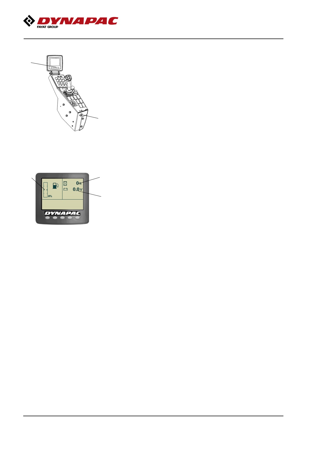
2
Sit down for all operations.
Turn the ignition key (1) to position I, the start screen
will be shown in display.
1
Fig. Control panel
1. Ignition key
2. Status screen
3
4
Check that the voltmeter (5) reads at least 24 volts,
and that the fuel gauge (3) show a reading.
The hourmeter (4) registers and shows the total
5
number of hours the engine has run.
Fig. Status image
3. Fuel level
4. Hourmeter
5. Voltmeter
2019-11-05
62
Operation
Interlock
The roller is equipped with Interlock.
The diesel engine with switch off after 7 seconds if the
operator gets off the seat when going
forwards/backwards.
If the control is in neutral when the operator stands up
a buzzer will go on until the parking brake is activated.
If the parking brake is activated, the diesel engine will
not stop if the forward/reverse lever is moved out of
neutral.
The diesel engine will switch off immediately if for any
reason the forward/reverse lever is moved out of
neutral when the operator is not sitting down and the
parking brake has not been activated.
Sit down for all operations!
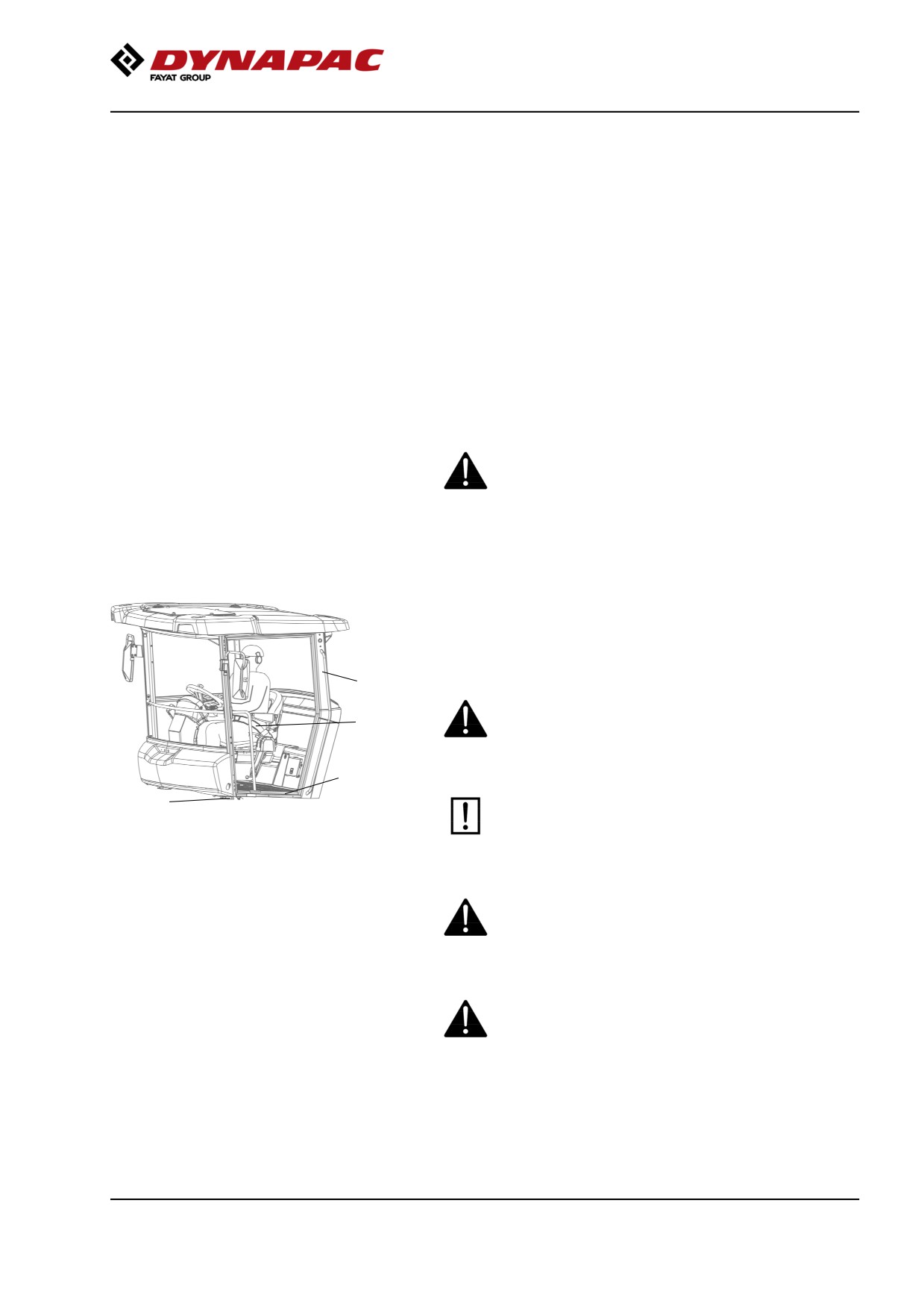
Operator position
If a ROPS (2) (Roll Over Protective Structure) or a cab
is fitted to the roller, always wear the seat belt (1)
provided and wear a protective helmet.
2
Replace the seat belt (1) if it shows signs of
1
wear or has been subjected to high levels of
force.
4
3
Check that rubber elements (3) on the platform
are intact. Worn elements will impair comfort.
Fig. Operator's station
1. Seat belt
2. ROPS structure
3. Rubber element
Ensure that the anti-slip (4) on the platform is in
4. Anti-slip
good condition. Replace where anti-slip friction is
poor.
If the machine is fitted with a cab, make sure that
the door is closed when in motion.
2019-11-05
63
Operation
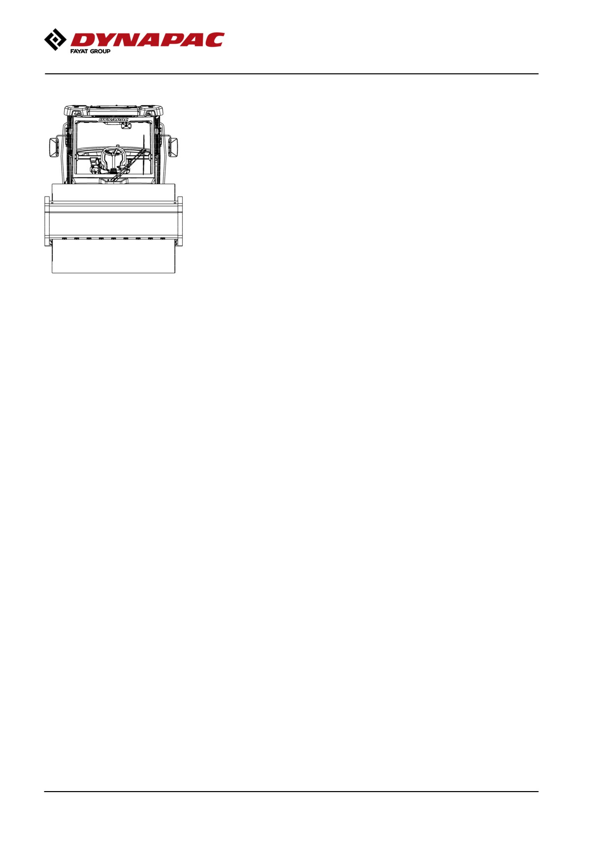
View
Before starting, make sure that the view forwards and
backwards is unobstructed.
All cab windows should be clean and the rear view
mirrors should be correctly adjusted.
Fig. view
2019-11-05
64
Operation
Starting
Starting the engine
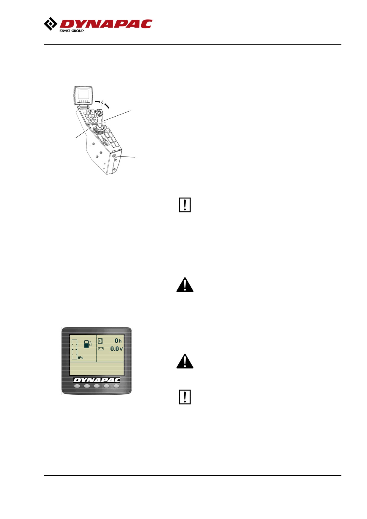
Make sure that the emergency stop is OFF and the
parking brake ON.
1
Set the forward/reverse lever (1) in neutral position,
and set the speed selector (2) in the idling position
(LO) or (ECO) if that option is installed on the machine.
The diesel engine cannot be started in any other
2
position of the controls.
3
Turn the ignition key (3) right to position I and then
engage the starter by turning it full right. Release back
to I as soon as the engine starts.
Fig. Control panel
1. F/R lever
2. Rpm switch
3. Ignition key
Do not run the starter motor for too long (max. 30
seconds). If the engine will not start, wait a
minute before trying again.
At the start of the diesel engine when the ambient
temperature is below +10 ° C (50 ° F), it must be
warmed up at idle (low speed) until the hydraulic oil
temperature exceeds +10 ° C (50 ° F).
Ensue that there is good ventilation (air extraction)
if the engine is run indoors. Risk of carbon
monoxide poisoning.
While the engine is warming up, check that the fuel
indicator shows the level and that the charge shows at
least 24V.
When starting and driving a machine that is cold,
remember that the hydraulic fluid is also cold and
that braking distances can be longer than normal
until the machine reaches the working temperature.
The machine always starts in Transport mode
Figure. Display - Status image
and without the option of vibration.
2019-11-05
65
Operation
Driving
Operating the roller
Under no circumstances is the machine to be
3
operated from the ground. The operator must be
seated inside the machine during all operation.
1
2
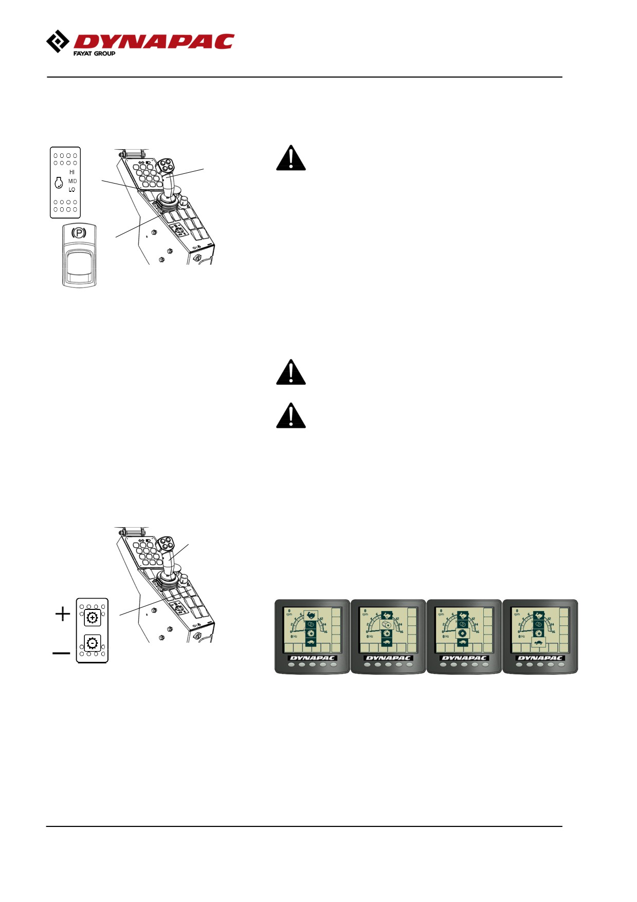
Activate working speed (1) = HI or ECO if available.
In ECO, the machine automatically regulates the
engine speed according to requirements.
If the machine is only to be transported, MID or ECO
Fig. Control panel
should be selected instead.
1. Speed selector
2. Parking brake
Check that the steering is working correctly by turning
3. Forward/Reverse lever
the steering wheel once to the right and once to the
left while the roller is stationary.
Make sure that the area in front of and behind the
roller is clear.
Release the parking brake (2).
Machine with gear change in separate
spring-return switch (gear position switch)
Switch (1) is a spring-return gear position switch,
2
where gear change is performed by advancing through
the four different gear positions: Hare, Drum spin,
Wheelspin and Tortoise.
1
Fig. Control panel
1. Gear position switch
2. Forward/Reverse lever
2019-11-05
66
Operation
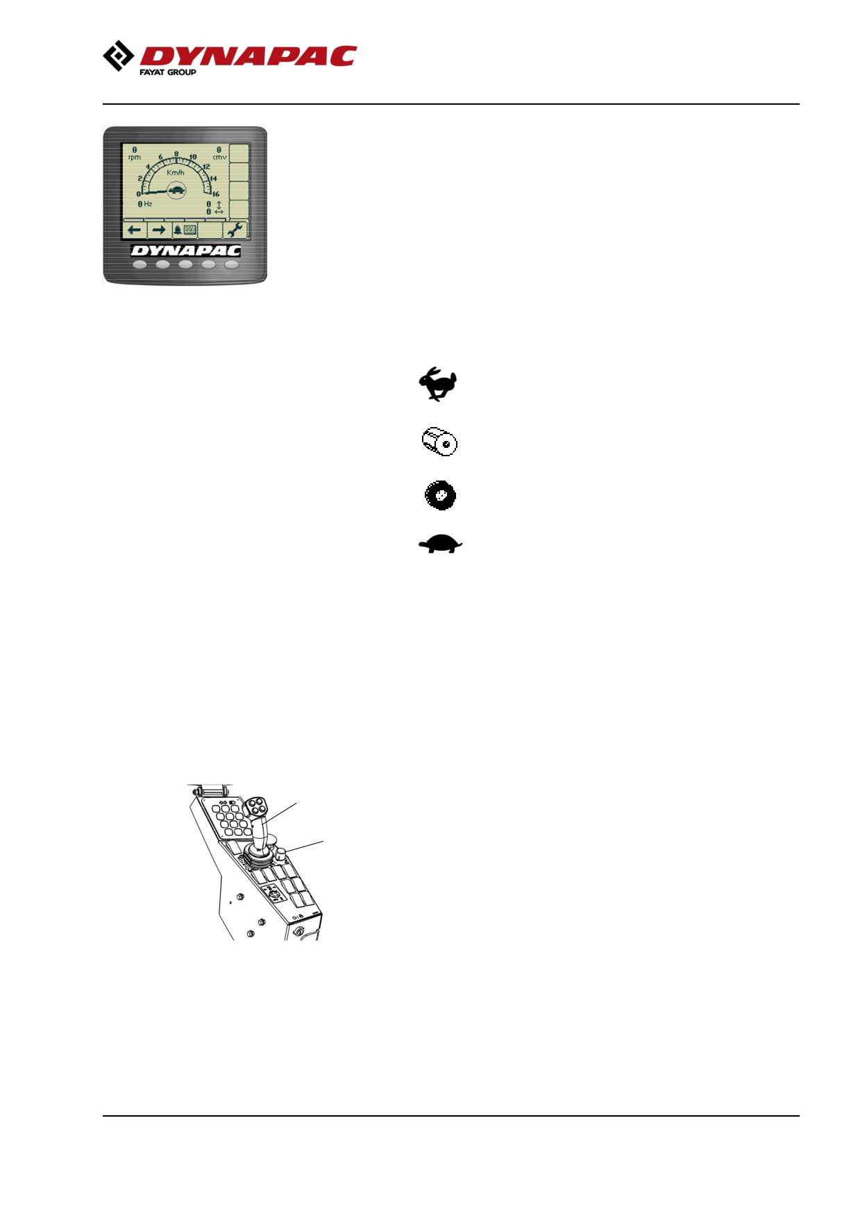
The machine's gear position is shown in the center of
the speedometer; select the gear/speed for the task.
The machine does not need to be stopped to change
gear position.
Fig. The display shows the selection in
the middle (tortoise, drum spin, wheelspin
or hare).
Max. speed
= Rabbit (4)
11,5 km/h
7 mph
= Drum spin (2)
8 km/h
5 mph
= Wheel spin (3)
7,5 km/h
4.5 mph
= Turtoise (1)
5,5 km/h
3.5 mph
Example is CA2500D, TC - Limited Slip Rear Axle (for other
alternatives see table in section for Technical data)
Carefully move the forward/reverse lever (2) forwards
or backwards, depending on which direction of travel
is required.
The speed increases as the lever is moved away from
the neutral position.
2
Machine with speed limiter (speed potentiometer) -
Optional.
1
Set the potentiometer (1) for variable speed setting in
the required mode.
The machine's gear position is shown in the center of
the speedometer. Select the gear/speed for the task.
Fig. Control panel
1. Potentiometer (speed limiter)
2. Forward/Reverse lever
2019-11-05
67
Operation
Carefully move the forward/reverse lever (2) forwards
or backwards, depending on which direction of travel
is required.
Speed increases as the lever is moved away from the
neutral position.
Fig. The display shows the selection in
the middle (tortoise, drum spin, wheelspin
or hare).
Driving on difficult surfaces
If the machine should get stuck, select the gear
position that is most suitable for the situation using the
gear position switch.
• Drum slipping - select Drum spin mode (gear position 2)
• Rear tires slipping - select Wheelspin mode (gear position
3)
Reset to the original position when the machine has
regained traction.
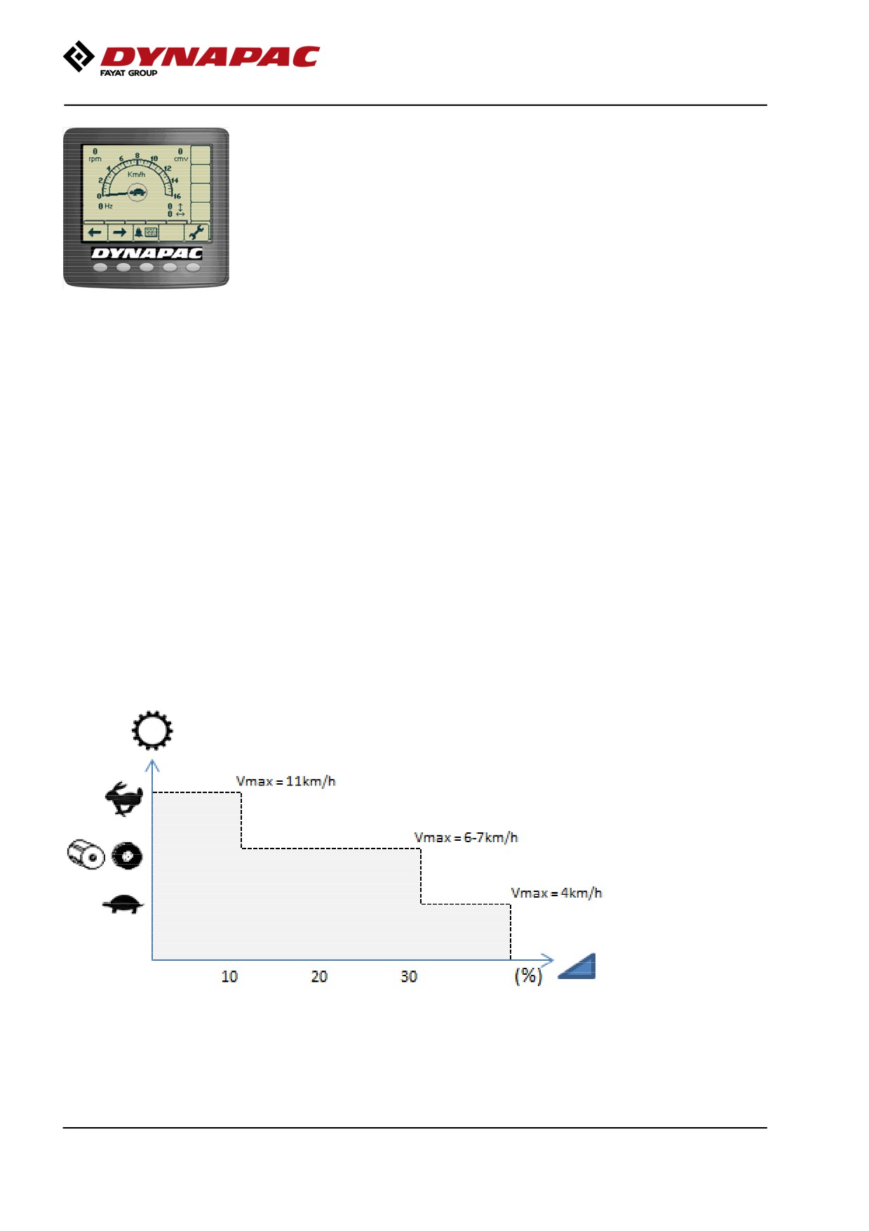
Slopes
To optimize available pulling force and protect the
machine's engine against over-revving while working
or during transport driving on steep slopes (>10%),
you must select low gear.
Never drive with a higher gear/at a faster speed that
the machine requires to climb up the same slope!
2019-11-05
68
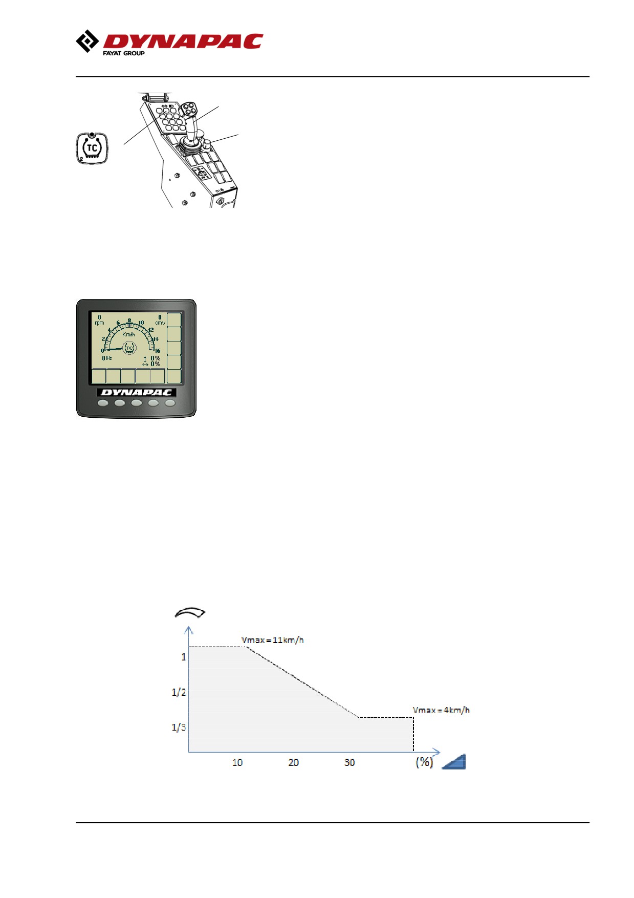
Operation
2
Machine with TC (Anti-Spin)
TC (Anti-Spin) (1) is activated by default (LED lit).
3
1
Position the speed control (3) in suitable position.
TC (Anti-Spin) activated/disengaged is shown in the
center of the speedometer.
Carefully move the forward/reverse lever (2) forwards
Fig. Control panel
1. TC (Anti-spin)
or backwards, depending on which direction of travel
2. Forward/Reverse lever
is required.
3. Potentiometer (speed limiter)
Speed increases as the lever is moved away from the
neutral position.
Fig. The display shows whether TC
(Anti-Spin) is activated or disengaged
Slopes (TC (Anti-Spin))
To optimize available pulling force and protect the
machine's engine against over-revving while working
or during transport driving on steep slopes (>10%),
you must select low setting on the speed limiter
(potentiometer).
Never drive with a higher gear/at a faster speed that
the machine requires to climb up the same slope!
2019-11-05
69