KEB COMBIVERT F5-A,-E,-H 4.0. APPLICATION MANUAL (2008) - page 23
CP-Parameter Definition
Target of these parameters is to allocate a set of parameter addresses to the control. By this way arbitrary in-
verter parameters with self-specified standardizations are addressed.
Required parameters
The following configuration parameters must be available for one programmable parameter.
·
Target address
·
Characteristics
The following settings can be made in the characteristics:
bit 0-7:
Target/source set with direct addressing
bit 8-11:
Mode of set-addressing:
0:
Target/source set of bit 0-7
1:
Target/source set = current set
2:
Target/source set = fr.9
3:
Accept target/source setting from PP-Para telegram
4...15:
free
Bit 12-13
Conversion mode
0:
standard
1:
Invers
2:
free
3:
free
Bit 14
Multiplier / write variable
0:
no
1:
yes
Bit 15
Shifter / write variable
0:
no
1:
yes
Bit 16
Multiplier / reading variable
0:
no
1:
yes
Bit 17
Shifter / reading variable
0:
no
1:
yes
Bit 18
Offset variable
0:
no
1:
yes
Bit 19-20
Read/Write rights
0:
Read/ Write
1:
Read-Only
The configuration parameters are inserted in the Ud.group and indirect addressed like the configuration para-
Page7.16 - 10
CP-Parameter Definition
meters of the CP parameters over a selector.
The following parameters result from it:
Ud.22:
PP selector
Value range: 0...47
Value range: -1(off)..7FFFH, only available and permitted
Ud.23:
PP address
addresses are acepted
Ud.24:
PP properties
Value range: 1...1023
Ud.25:
PP write multiplier
Value range: +/- 32767
Ud.26:
PP write shifter
Value range: 0..48
Ud.27:
PP read multiplier
Value range: +/- 32767
Ud.28:
PP read shifter
Value range: 0..48
Ud.29:
PP offset
Value range: +/- 2^31 -1
Ud.30:
PP upper limit
Value range: +/- 2^31 -1
Ud.31:
PP lower limit
Value range: +/- 2^31 -1
Example
Reading of the prog. parameters
The values of the source parameter in the selected sets are compared. If all values are equal then this value is
displayed, otherwise „data invalid“ is displayed. If no source parameter is defined, „data invalid“ is displayed.
Writing of the prog. parameters
7
The write value is written into all selected sets of the target parameter.
The following characteristics of the target parameter are checked:
Exceeding the limits: „invalid data“
Generally write protection: „write protected parameters“
Wwrite protection at switch on modulation: „operation not possible“
Write protection in the active set: „invalid set“
Password: ‘Password invalid‘ is only displayed at parameters with supervisor-password
„Data invalid“ is always displayed if no source parameter is defined.
Invalid target/source parameters
Some parameters cannot be adjusted as target/source parameter in ud.23. There are all parameters, which are
not permissible as CP parameter (characteristics 2 bits 15 = 1) or process date (characteristics 1 bit 28 = 1), as
well as the prog. parameters itself. Explanation:
-
all sy parameters exception sy.02, 06, 07, 32, 41-44, 50-53
-
uf.12-14
-
all ud parameters exception ud.01, 09
-
fr.01
-
in.20,21,31-33
-
Ec.00,10,36-38
-
aa.00-13, 26-29, 34-41
-
pp.00-47
Page7.16 - 11
CP-Parameter Definition
Prog. parameters as process data
The prog. parameters can be used as process data. Restrictions occur only if a prog. parameter is assigned
with a process date invalid parameter. In this case the process date is switched off and the adjusted address
in the corresponding sy parameter is negated, in order to mark this process date as switched off. This applies
also if the prog. parameter is switched off (ud.23 = -1).
A prog. parameter is additionally invalid as process write date, in case the target parameter is write protected
(generally, when the modulation is switched on, in active set).
The set definition of the process date is always valid as set source for process data (e.g. sy.17 for process read
date 1). The adjustment in ud.24 is without meaning.
Prog. parameters as scope data
The prog. parameters can be used as scope data. If the selected prog. parameter is switched off (ud.23 = -1)
the scope date is switched off and the adjusted address in the corresponding sy-parameter is negated, in order
to mark this scope date switched off.
Since the prog. parameters have the type LONG they cannot be assigned on Scope channel 3 and 4, without
Combivis leaves the fast scope mode.
The set definition of the process date is always valid as set source for process data (e.g. sy.34 for scope date
1). The adjustment in ud.24 is without meaning.
Page7.16 - 12
Troubleshooting
1.
Introduction
2.
Summary
3.
Hardware
4.
Operation
Selection of Operating
5.
Mode
6.
Initial Start-up
7.
Functions
8.
Error Assistance
8.1
Troubleshooting
8
9.
Project Design
10. Networks
11. Parameter Overview
12. Annex
Page8.1 - 1
Troubleshooting
8.1.1
General
8.1 - 3
8.1.2
Error messages and their causes
8.1 - 3
Page8.1 - 2
Troubleshooting
8. Error Assistance
The following chapter shall help you to avoid errors as well as help you to determine and remove the cause of
errors on your own. There is the error messages of all KEB COMBIVERT F5 represented, although depending
upon equipment and execution some are missing.
8.1
Troubleshooting
8.1.1
General
If error messages or malfunctions occur repeatedly during operation, the first thing to do is to pinpoint the exact
error. To do that go through the following checklist:
- Is the error reproducable?
For that reset the error and try to repeat it under the same conditions. If the error can be reproduced, the next
step is to find out during which operating phase the error occurs.
- Does the error occur during a certain operating phase (e.g. always during acceleration)?
If so, consult the error messages and remove the causes listed there.
- Does the error occur or disappear after a certain time?
That may be an indication for thermal causes. Check, whether the inverter is used in accordance to the ambient
conditions and that no moisture condensation takes place.
8.1.2
Error messages and their causes
At KEB COMBIVERT error messages are always represented with an "E." and the appropriate error in the dis-
play. Error messages cause the immediate deactivation of the modulation. Restart possible only after reset.
Malfunction are represented with an " A." and the appropriate message. Reactions to malfunctions can vary.
Status messages have no addition. The status message shows the current operating status of the inverter (e.g.
forward constant run, standstill etc.).
8
In the following the display and their cause are described.
Display
COMBIVIS
Value
Meaning
Status messages
bbL
base block
76
Power modules for motor de-excitation locked
bon
close brake
85
Brake control, brake engaged (see chapter 6.9)
boFF
open brake
86
Brake control, brake released (see chapter 6.9)
Cdd
calculate drive
82
Measurement of the motor stator resistance
dcb
DC brake
75
Motor is decelerated by a DC-voltage at the output.
Modulation is switched off after DC braking (see chapter 6.9 “DC
dLS
low speed / DC brake
77
braking”).
Acceleration with the adjusted ramps in clockwise direction of
FAcc
forward acceleration
64
rotation.
Acceleration / deceleration phase is completed and it is driven with
Fcon
forward constant
66
constant speed / frequency in clockwise direction of rotation.
It is stopped with the adjusted ramp times in clockwise direction of
FdEc
forward deceleration
65
rotation.
further on next side
Page8.1 - 3
Troubleshooting
Display
COMBIVIS
Value
Meaning
The message is output if the output current reaches the hardware
HCL
hardware current limit
80
current limit.
This message is displayed if during acceleration the load is limited to
LAS
LA stop
72
the adjusted load level.
This message is displayed if during deceleration the load is limited to
LdS
Ld stop
73
the adjusted load level or the DC-link current to the adjusted voltage
level.
LS
low speed (mod. off)
70
No direction of rotation pre-set, modulation is off.
nO_PU
power unit not ready
13
Power circuit not ready or not identified by the control.
noP
no operation
0
Control release (terminal ST) is not switched.
PA
positioning active
122
This message is displayed during a positioning process.
PLS
low speed / power off
84
No modulation after Power-Off.
The specified position cannot be reached within the pre-set ramps.
PnA
position not reachable
123
The abort of the positioning can be programmed.
Depending on the programming of the function (see chapter 6.9
POFF
power off function
78
„Power-off Function“) the inverter restarts automatically upon system
recovery or after a reset.
POSI
positioning
83
Positioning function active (F5-G).
Acceleration with the adjusted ramp times in anti-clockwise direction
rAcc
reverse acceleration
67
of rotation.
Acceleration / deceleration phase is completed and it is driven with
rcon
reverse constant
69
constant speed / frequency in clockwise direction of rotation.
It is stopped with the adjusted ramp times in anti-clockwise direction
rdEc
reverse deceleration
68
of rotation.
rFP
ready for positioning
121
The drive signals that it is ready to start the positioning process.
This message is displayed if during constant operation the load is
SLL
stall
71
limited to the adjusted current limit.
SrA
search for ref. active
81
Search for reference point approach active.
Speed search function active, that means that the inverter attempts
SSF
Speed search
74
to synchronize onto a running down motor.
The message is output if as response to a warning signal the quick-
Stop
quick stop
79
stop function becomes active.
PrF
prot. rot. for.
124
protected direction of rotation forward
Prr
prot. rot. rev.
125
protected direction of rotation reverse
IPnA
pos.not accessib.ignored
126
Position not accessible ignored
Cddr
calc. drive data ready
127
Calculation drive data ready
SrF
reference found
128
Reference point found (only special version)
Error messages
Error: can occur in the case of switched on brake control (see chapter
6.9.5), if
E. br
Error ! Brake control
56
if the load during the start is below the minimum load level (Pn.43) or
the missing of a motor phase is recognized.
the load is too high and the hardware current limit is reached.
Error:Adjusted monitoring time (Watchdog) of communication between
E.buS
Error ! Watchdog
18
operator and PC / operator and inverter has been exceeded.
E.Cdd
Error ! calc. drive data
60
Error: During the automatic motor stator resistance measurement.
E.co1
Error ! counter overrun 1
54
Counter overflow encoder channel 1
further on next side
Page8.1 - 4
Troubleshooting
Display
COMBIVIS
Value
Meaning
E.co2
Error ! counter overrun 2
55
Counter overflow encoder channel 2
Error: Overtemperature of motor PTC. Error can only be reset at
E.ndOH, if PTC is again low-resistance. Causes:
E.dOH
Error ! drive overheat
9
Resistance at terminals T1/T2 >1650 Ohm
Motor overloaded
Line breakage to the temperature sensor
Error: Driver relay. Relay for driver voltage on power circuit has not
E.dri
Error ! driver relay
51
picked up even though control release was given.
After reset the operation is again possible (without storage in the
E.EEP
Error ! EEPROM defective
21
EEPROM)
Is triggered, if a digital input is being programmed as external error
E. EF
Error ! ERROR external fault
31
input and trips.
E.EnC
Error ! encoder channel
32
Cable breakage at resolver or incremental encoder
E.Hyb
Error ! Encoder interface
52
Invalid encoder interface identifier.
Error: Encoder interface identifier has changed, it must be confirmed
E.HybC
Error ! hybrid changed
59
over Ec.0 or Ec.10.
Hardware error at NPN-/PNP change-over or at start/stop
E.iEd
Error ! input error detect
53
measurement.
E.InI
Error ! MFC not booted
57
MFC not booted
Error: Load-shunt relay has not picked up, occurs for a short
time during the switch-on phase, but must automatically be reset
immediately. If the error message remains the following causes may
be applicable:
E.LSF
Error ! load shunt fault
15
load-shunt defective
input voltage wrong or too low
high losses in the supply cable
braking resistor wrongly connected or damaged
braking module defective
Motor temperature switch or PTC at the terminals T1/T2 is again in
E.ndOH
no ERROR drive overheat
11
the normal operating range. The error can be reset now.
Temperature of the heat sink is again in the permissible operating
E.nOH
no E. over heat pow.mod.
36
8
range. The error can be reset now.
No longer overheating in the interior E.OHI, interior temperature has
E.nOHI
no ERROR overheat int.
7
fallen by at least 3°C
No more overload, OL-counter has reached 0%; after the error E.OL a
cooling phase must elapse. This message appears upon completion
E.nOL
no ERROR overload
17
of the cooling phase. The error can be reset now. The inverter must
remain switched on during the cooling phase.
E.nOL2
no ERROR overload 2
20
The cooling time has elapsed. The error can be reset.
Occurs, if the specified peak current is exceeded. Causes:
acceleration ramps too short
the load is too big at switched off acceleration stop and switched off
constant current limit
short-circuit at the output
E.OC
Error ! overcurrent
4
ground fault
deceleration ramp too short
motor cable too long
EMC
DC brake at high ratings active (see 6.9.3)
further on next side
Page8.1 - 5
Troubleshooting
Display
COMBIVIS
Value
Meaning
Overtemperature of power module. Error can only be reset at E.nOH.
Causes:
E.OH
Error ! overheat pow.mod.
8
insufficient air flow at the heat sink (soiled)
ambient temperature too high
ventilator clogged
E.OH2
Error ! motor protection
30
Electronic motor protective relay has tripped.
Overheating in the interior: error can only be reset at E.nOHI, if the
E.OHI
Error ! overheat internal
6
interior temperature has dropped by at least 3 °C.
Overload error can only be reset at E.nOL, if OL-counter reaches
0% again. Occurs, if an excessive load is applied longer than for the
permissible time (see technical data).Causes:
poor controller adjustment
E.OL
Error ! overload (Ixt)
16
mechanical fault or overload in the application
inverter not correctly dimensioned
motor wrongly wired
encoder defective
Occurs if the standstill constant current is exceeded (see technical
E.OL2
Error ! overload 2
19
data and overload characteristics). The error can only be reset if the
cooling time has elapsed and E.nOL2 is displayed.
Voltage in the DC-link circuit too high. Occurs if the DC-link voltage
exceeds the permissible value. Causes:
poor controller adjustment (overshooting)
E.OP
Error ! overvoltage
1
input voltage too high
interference voltages at the input
deceleration ramp too short
braking resistor defective or too small
E.OS
Error ! over speed
58
Real speed is bigger than the max. output speed.
E.PFC
Error ! PFC
33
Error in the power factor control
The drive has driven onto the right limit switch. Programmed response
E.PrF
Error ! prot. rot. for.
46
“Error, restart after reset” (see chapter 6.7 “Response to errors or
warning messages”).
The drive has driven onto the left limit switch. Programmed response
E.Prr
Error ! prot. rot. rev.
47
“Error, restart after reset” (see chapter 6.7 “Response to errors or
warning messages”).
E. Pu
Error ! power unit
12
Error: General power circuit fault
Error: During the initialization the power circuit could not be recognized
E.Puci
Error ! power circuit unknown
49
or was identified as invalid.
Error: Power circuit identification was changed; with a valid power
circuit this error can be reset by writing to SY.3. If the value displayed
in SY.3 is written, only the power-circuit dependent parameters
E.Puch
Error ! power unit changed
50
are reinitialized. If any other value is written, then the default set is
loaded. On some systems after writing Sy.3 a Power-On-Reset is
necessary.
Error ! power circuit
Error: Parameter value could not be written to the power circuit.
E.PUCO
22
communication
Acknowledgement from LT <> OK
Error: Software version for power circuit and control card are different.
E.PUIN
Error ! power circuit coding
14
Error cannot be reset (only at F5-G B-housing)
Sychronization over sercos-bus not possible. Programmed response
E.SbuS
Error ! bus synchron
23
“Error, restart after reset”.
further on next side
Page8.1 - 6
Troubleshooting
Display
COMBIVIS
Value
Meaning
It has been attempted to select a locked parameter set. Programmed
E.SEt
Error ! set
39
response “Error, restart after reset”.
The target position lies outside of the limit defined with the right
Error ! Software limit switch
E.SLF
44
software limit switch. Programmed response “Error, restart after
forward
reset”.
Error ! software limit switch
The target position lies outside of the limit defined with the left software
E.SLr
45
reverse
limit switch. Programmed response “Error, restart after reset”.
Error: Undervoltage (DC-link circuit). Occurs, if DC-link voltage falls
below the permissible value. Causes:
input voltage too low or unstable
inverter rating too small
voltage losses through wrong cabling
the supply voltage through generator / transformer breaks down at
E. UP
Error ! underpotential
2
very short ramps
at F5-G B housing E.UP is also displayed if no communication takes
place between power circuit and control card.
jump factor (Pn.56) too small
if a digital input was programmed as external error input with error
message E.UP (Pn.65).
E.UPh
Error ! Phase failure
3
One phase of the input voltage is missing (ripple-detection)
Warning Messages
Warning: Watchdog for communication between operator/control
A.buS
Warning ! Watchdog
93
card or operator/PC has responded. The response to this warning
can be programmed.
The motor temperature has exceeded an adjustable warning level.
The switch off time is started. The response to this warning can be
A.dOH
Warning ! drive overheat
96
programmed. This warning can be generated only with a special
power circuit.
Warning ! ERROR external
This warning is triggered via an external input. The response to this
A. EF
90
fault
warning can be programmed.
The motor temperature is again below the adjusted warning level.
A.ndOH
no ABN.STOP drive overheat
91
8
The switch off time is stopped.
no ABN.STOP overheat pow.
The heat sink temperature is again below the adjusted warning
A.nOH
88
mod.
level.
no ABN.STOP overheat
The temperature in the interior of the inverter is again below the
A.nOHI
92
internal
warning threshold.
Warning: no more overload, OL counter has reached 0 %, warning
A.nOL
no ABN.STOP overload
98
„overload" can be reset.
The cooling time after “Warning! Overload during standstill" has
A.nOL2
no ABN.STOP overload 2
101
elapsed. The warning message can be reset.
A level can be defined, when it is exceeded this warning is output.
A. OH
Warning ! overheat pow.mod.
89
Furthermore the response to this warning can be programmed.
Warning: electronic motor protective relay has tripped. The response
A.OH2
Warning ! motor protection
97
to this warning can be programmed.
The temperature in the interior of the inverter lies above the
A.OHI
Warning ! overheat internal
87
permissible level. The switch off time was started. The programmed
response to this warning message is executed.
further on next side
Page8.1 - 7
Troubleshooting
Display
COMBIVIS
Value
Meaning
A level between 0 and 100 % of the load counter can be adjusted,
A. OL
Warning ! overload
99
when it is exceeded this warning is output. The response to this
warning can be programmed.
The warning is output when the standstill continuous current is
exceeded (see technical data and overload characteristics). The
A.OL2
Warning ! overload 2
100
response to this warning can be programmed. The warning message
can only be reset after the cooling time has elapsed and A.nOL2 is
displayed.
The drive has driven onto the right limit switch. The response to this
A.PrF
Warning ! prot. rot. for.
94
warning can be programmed.
The drive has driven onto the left limit switch. The response to this
A.Prr
Warning ! prot. rot. rev.
95
warning can be programmed.
Sychronization over sercos-bus not possible. The response to this
A.SbuS
Warning ! Bus synchron
103
warning can be programmed.
It has been attempted to select a locked parameter set. The response
A.SEt
Warning ! set
102
to this warning can be programmed.
Warning ! Software limit
The target position lies outside of the limit defined with the right software
A.SLF
104
switch forward
limit switch. The response to this warning can be programmed.
Warning ! software limit
The target position lies outside of the limit defined with the left software
A.SLr
105
switch reverse
limit switch. The response to this warning can be programmed.
Page8.1 - 8
General Designs
1.
Introduction
2.
Summary
3.
Hardware
4.
Operation
Selection of Operating
5.
Mode
6.
Initial Start-up
7.
Functions
9.1
General designs
8.
Error Assistance
9.
Project Design
9
10. Networks
11. Parameter Overview
12. Annex
Page9.1 - 1
General Designs
9.1.1
Control cabinet design calculation
9.1 - 3
9.1.2
Design of braking resistors
9.1 - 4
9.1.3
Cables and fuses
9.1 - 6
Page9.1 - 2
General Designs
9. Project Design
The following chapter shall assist you in the planning stage of applications.
9.1
General designs
9.1.1
Control cabinet design calculation
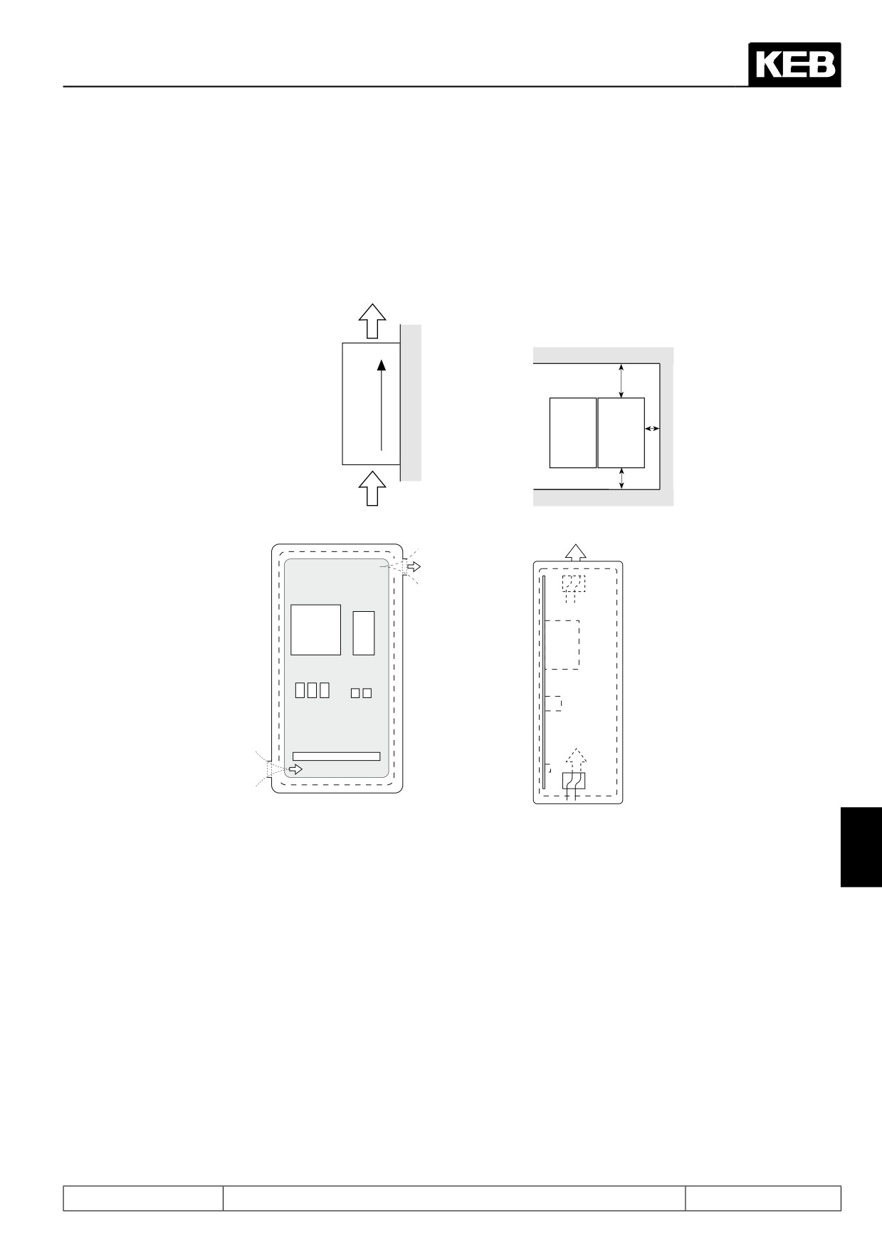
Direction of
Minimum distances
cooling fins
150
30
F5
F5
100
Warm air
outlet
KEB
COMBIVERT
Cool air inlet
Control cabinet surface
9
Calculation of control cabinet surface:
Air flow rate with fan cooling:
PV
3,1 • PV
A =
————
[m2]
V =
————
[m3/h]
∆T • K
∆t
A
=
Control cabinet surface
[m2]
∆t
=
temperature differential
[K]
(standard value = 20K)
K
=
coefficient of heat transmission
(default value = 5)
PV
power loss (see technical data)
V
=
air flow rate of fan
For more details please refer to the catalogs of the control cabinet manufacturers.
Page9.1 - 3
General Designs
9.1.2
Design of braking resistors
The KEB COMBIVERT fitted with an external braking resistor or an external braking option is suitable for a
limited 4-quadrant operation. The braking energy, refeed into the DC-bus at generatoric operation, is dissipated
over the braking transistor to the braking resistor.
The braking resistor heats up during the braking process. If it is installed in a control cabinet sufficient cooling
of the control cabinet interior and sufficient distance to the KEB COMBIVERT must be observed.
Different braking resistors are available for the KEB COMBIVERT. Please refer to the next page for the corre-
sponding formula and restrictions (valid range).
1. Preset desired braking time.
2. Calculate braking time without braking resistor (tBmin).
3. If the desired braking time shall be smaller than the calculated time, it is necessary to use a braking resistor.
(tB < tBmin)
4. Calculate braking torque (MB). Take the load torque into account at the calculation.
5. Calculate peak braking power (PB). The peak braking power must always be calculated for the worst case (nmax to standstill).
6. Selection of braking resistor:
PR > PB
a)
PN is to be selected according to the cycle time(ED).
b)
The braking resistors may be used only for the listed unit sizes. The maximum cyclic duration of a braking re-
sistor shall not be exceeded.
6 % ED =
maximum braking time
8 s
25 % ED =
maximum braking time
30 s
40 % ED =
maximum braking time
48 s
For a longer cyclic duration time special designed braking resistors are necessary. The continuous output of the
braking transistor must be taken into consideration.
7. Check, whether the desired braking time is attained with the braking resistor (tBmin).
Restriction:
Under consideration of the rating of the braking resistor and the brake power of the motor, the braking torque
may not exceed 1,5times of the rating torque of the motor (see formula).
When utilizing the maximum possible braking torque the frequency inverter must be dimensioned for the higher
current.
Braking time DEC
The braking time DEC is adjusted at the frequency inverter. If it is chosen too small the KEB COMBIVERT
switches off automatically and the error message OP or OC appears. The approximate braking time can be
determined according to following formula.
Page9.1 - 4
General Designs
Formula
1. Braking time without braking resistor
2. Braking torque (necessary)
(JM + JL) • (n1 - n2)
(JM + JL) • (n1 - n2)
tBmin
=
——————————
MB =
————————
- ML
9,55 • (K • MN + ML)
9,55 • tB
Valid range: n1 > nN
Condition:
MB < 1.5 • MN
(Field weakening range)
f < 70 Hz
3. Peak braking power
4. Braking time with braking resistor
(JM + JL) • (n1 - n2)
MB • n1
PB =
—————
tBmin *
————————————————
9,55
PR • 9,55
9,55 • K• MN+ M
+
—————
L
(n1 - n2)
Condition:
PB
Valid range: n1 > nN
< PR
PR • 9,55
Condition:
< M
——————
N • (1,5 -K)
(n1 - n2)
f
< 70 Hz
PB < PR
K=
0,25 for motors
upto
1,5 kW
JM
=
mass moment of inertia motor
[kgm2]
0,20 for motors
2,2
4 kW
JL
=
mass moment of inertia load
[kgm2]
upto
0,15 for motors
5,5
11 kW
n1
=
motor speed prior to deceleration
[rpm]
upto
9
0,08 for motors
15
45 kW
n2
=
motor speed after deceleration
[rpm]
upto
(standstill = 0 rpm)
0,05 for motors
>
45 kW
nN
=
rated motor speed
[rpm]
MN
=
rated motor torque
[Nm]
MB
=
braking torque (necessary)
[Nm]
ML
=
load torque
[Nm]
t
=
braking torque (necessary)
[s]
B
t
=
minimum braking time
[s]
min
t
=
cycle time
[s]
Z
PB
=
peak braking power
[W]
PR
=
peak power of braking resistor
[W]
Page9.1 - 5
General Designs
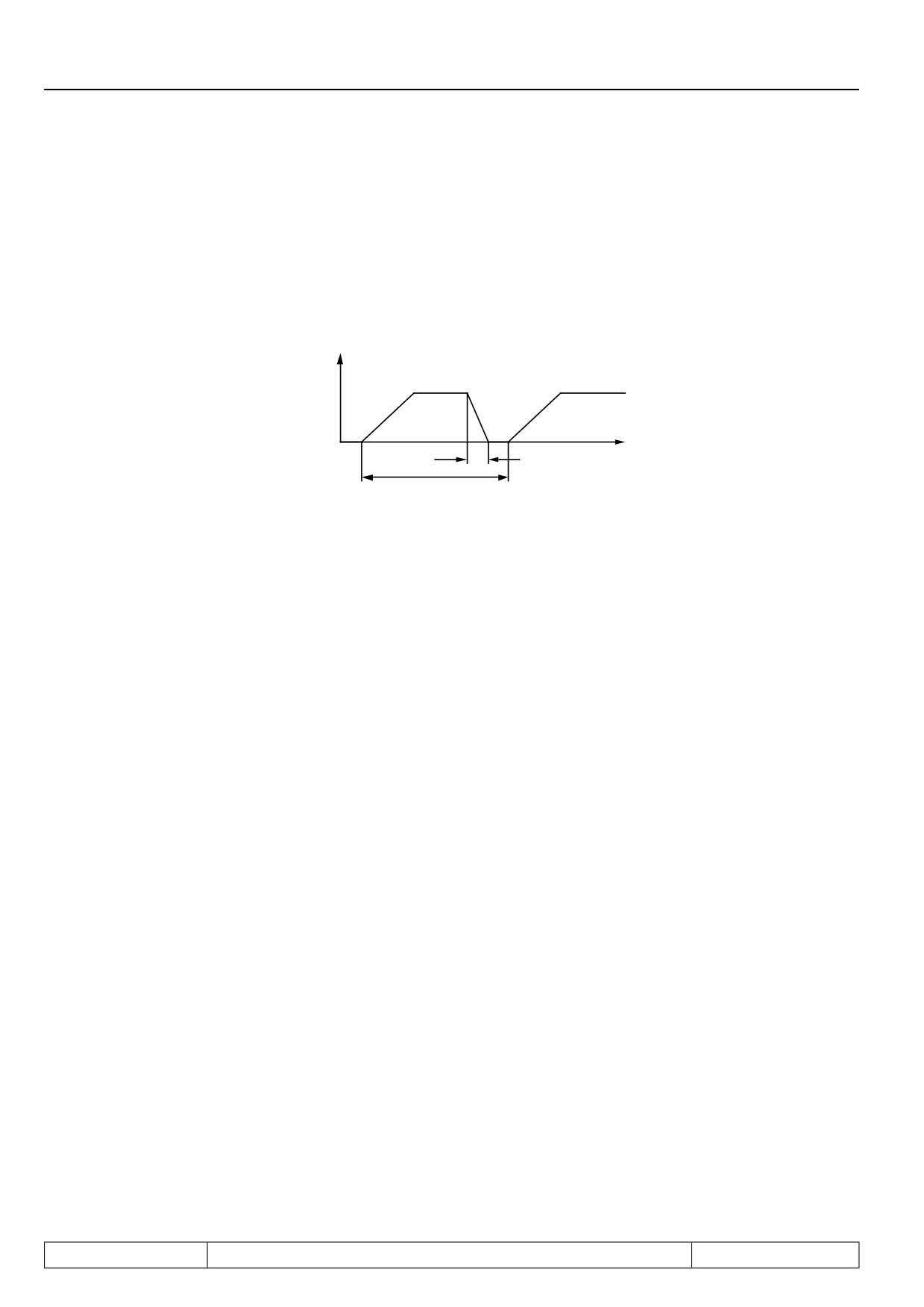
Cyclic duration factor (cdf)
Cyclic duration factor for cycle time tZ < 120 s
Cyclic duration factor for cycle time tZ > 120 s
tB
tB
ED =
———
• 100 %
ED =
———
• 100 %
tZ
120 s
f
t
tB
tZ
9.1.3
Cables and fuses
By means of this section you can check whether you can still optimize your machine with regard to the material
usage. The specifications are derived for the DIN VDE 0298 Part 4. The values apply approximately and only
for the intended operation. In marginal cases it must be always proceed according to the standard described
obove.
The following table shows the current capability of 3 and/or 5 core PVC cables (i.e. 2 and/or 3 loaded cores)
in dependence with the ambient temperature. The current is to be laid out to the input current of the frequency
inverter.
The use of special cables or the way of laying the cables allows even higher currents (see DIN VDE 0298 Part
4). The motor cable must correspond to the cross-section of the mains cable.
If in case of long lines (>30m) still maximum torque is required at the motor shaft, the cable should be dimensi-
oned for the next larger cross-section in order to reduce line resistances.
Mains fuses are to be designed for the rated input current of the inverter. The current/time-characteristic of
the fuse must be slow-acting in order to avoid premature tripping when the power reserves of the inverter are
used.
Page9.1 - 6
Network Components
1.
Introduction
2.
Summary
3.
Hardware
4.
Operation
Selection of Operating
5.
Mode
6.
Initial Start-up
10.1
Network components
7.
Functions
8.
Error Assistance
9.
Project Design
10. Networks
10
11. Parameter Overview
12. Annex
Page10.1 - 1
Network Components
10.1.1
Available hardware
10.1 - 3
10.1.2
RS232-cable PC / operator 00.58.025-001D
10.1 - 3
10.1.3
HSP5-cable / control board 00.F5.0C0-0010
10.1 - 4
10.1.4
Interface operator F5 00.F5.060-2000
10.1 - 4
10.1.5
Profibus-DP operator F5 00.F5.060-3000
10.1 - 5
10.1.6
InterBus operator F5 00.F5.060-4000 / 4001
10.1 - 6
10.1.7
CanOpen operator F5 00.F5.060-5010 / 5011
10.1 - 7
10.1.8
Sercos operator 00.F5.060-6000
10.1 - 8
Page10.1 - 2
Network Components
10. Networks
10.1 Network components
10.1.1Available hardware
The KEB COMBIVERT F5 can be easily integrated into different networks. For that purpose the inverter is
fitted with an operator that is appropriate for the respective bus system. Following hardware components are
available:
-
RS232-Cable PC/operator
Part No.:
00.58.025-001D
for operation with interface operator
-
HSP5-Adaptor PC/control board
Part No.:
00.F5.0C0-0001
for operation without operator; RS232 => TTL
-
F5 Interface-operator
Part No.:
00.F5.060-2000
serial networks in RS232 or RS485 standard
-
F5 Profibus-DP-operator
Part No.:
00.F5.060-3000
–
F5 InterBus-operator
Part No.:
00.F5.060-4000
–
InterBus-Remote bus interface connection Part No.:
00.B0.0BK-K001
(in connection with Interface-Operator)
-
F5 CanOpen-operator
Part No.:
00.F5.060-5000
-
F5 Sercos-operator
Part No.:
00.F5.060-6000
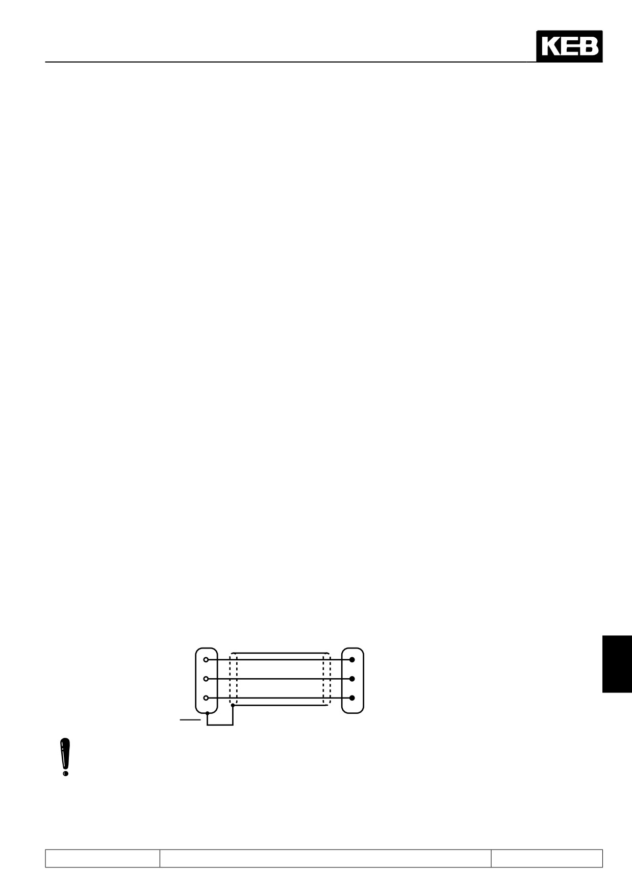
10.1.2RS232-cable PC / operator 00.58.025-001D
The cable of 3m length is used for the direct RS232-connection between PC (9-pole SUB-D-connector) and
operator.
9-pole SUB-D coupling
9-pole SUB-D connector
2
2
10
3
3
5
7
Housing (PE)
PC
F5-Operator
The RS232 cable is suitable exclusively for the communication between PC and operator. If the cable is plugged
in directly onto the control board, it can lead to the desctruction of the interface of the PC.
Page10.1 - 3