KEB COMBIVERT F5-A,-E,-H 4.0. APPLICATION MANUAL (2008) - page 21
Parameter Sets
Parameters only with KEB-Default value
Bit 27 is set in characteristics 2 for parameters, which contains only the KEB default value. These are among
others all security parameters and all write protected parameters.
During loading the specific default values (fr.01 = -5..-8) these parameters are loaded with KEB default values
if necessary.
Indirect addressed Parameters
The indicator parameter (first parameter of an indirect addressed group) has not a customer default value, be-
cause the parameter was set to 0 with Power-On-Reset. The parameters belonging to the group have a default
value for each value of the indicator.
Storing the custom-specific default values
A source table is generated. For this one byte is reserved for each parameter in the sequence of the bus
addresses. This byte contains the information for each set, whether the default value is determined from the
parameter definition (= 0, KEB default value) or if the value is stored in the custom-specific storage area (= 1).
This information is determined by comparison to the KEB default value.
For indirect addressed parameters the number of reserved bytes for each group member is equal to the number
of valid values of the indicator. 36 byte are reserved for ud.16 and ud.17, ud.15 = 1...36. 16 byte are reserved
for ps.24...27, ps.23 = 0...15. The custom-specific default values are stored in the sequence of the bus addres-
ses (ascending) set depending (set 7..0).
The custom-specific default values for indirect addressed parameters are stored first to bus address (ascen-
ding), then to indicator value (max
min.), then set-dependent (set 7..0).
Example: Default value ud.09, default values ud.16 for ud.15 = 36..1, default values ud.17 for ud.15 = 36..1,
default values ud.18 for set 7..0, etc.
Copy custom-specific default values in the sets
With the bits in the source table the default value for each set is determined either from the parameter definition
for each parameter in the sequence of the bus address or read-out from the custom-specific memory area and
written into the parameter.
Parameters only with KEB default value are loaded with the KEB default value in this case.
Reset of the custom-specific default values
The default values are reset for all parameters to KEB default values in the following cases:
-
All parameters are set to default values (initial loading)
-
The version identification of the software changes (new version, or new date code)
-
The control type is changed (ud.02 bit 2+3)
Page7.14 - 6
Parameter Sets
The custom-specific default values can be reset manually as follows:
-
Loading KEB default values in all sets (fr.01 = -4)
-
Storing defaul values (fr.01 = -9)
Changed power unit or encoder identifier, changeover standard/US setting
The power unit identification was changed:
-
The power unit identifiction dependent KEB default values are adapted.
-
If necessary uf.11 is limited in all sets to the maximal switching frequency (in.03).
-
If a custom-specific default value of uf.11 is not within the value range (0..in.03)uF.11 is loaded during
default value loading in the corresponding set with the KEB default value.
-
If the write value of sy.03 is unequal to the reading power unit identification, all customer and system
parameters are loaded with KEB default values (corresponding Fr.01 = -4).
The encoder identifier was changed:
-
The encoder identifier dependent KEB default values are adapted.
-
EC-Parameters are loaded with KEB default values.
-
Changeover standard/US setting (change in.21 bit 0 at in.20 = 32):
-
The KEB default values depending on this setting are adapted.
-
Customer and system parameters are loaded with KEB default values (corresponding to Fr.01 = -4).
7
Memory management
The length of the source table (in byte) and the length of the memory area of the customer default values (in
byte) are stored in one word at the end of the external RAM.
The source table for the custom-specific default value range is in front of these two cells. The length is depen-
dent on the number of permitted parameters of the adjusted control type (ud.02 bit 2+3)
The memory area for the custom-specific default values starts next to the source table. The length is dependent
on the number of values stored here. Only the values which are different to the KEB default values are stored.
The default values are stored in descending order of memory addresses.
The off-line memory includes the period between the temporary variables and the memory area for the custom-
specific default values. The size of the off-line memory is depending on the number of custom-specific default
values.
Complete use of the available memory
Fr.01 = -10 (customer default memory is full) is set if the memory area is completely filled with custom-specific
default values, all values could not be stored.
That means only one part of the parameter setting (with low bus addresses) contain custom-specific default
values, further settings only contain KEB default values.
This restriction should not occur since enough memory is available.
Page7.14 - 7
Parameter Sets
7.14.7Parameter set selection
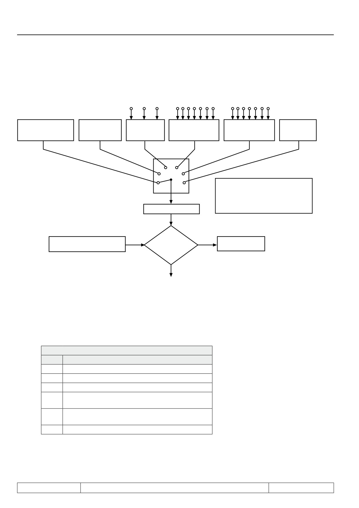
Figure 7.14.7 Principle of the parameter set selection
22
21
20
76543
2
1
76543 21
digital
set selection deacti-
Fr.4 via
terminal strip
terminal strip
SY.50 with
Terminal strip
vated
keyboard/bus
binary coded
binary coded
control word
binary coded
always set 0 active
ST>RST>...>ID
ID>IC>...>ST
(only bus)
1234
5
ATTENTION! The valency at Fr.2
0
Fr.2
= 2...4 is generally ID > IC > ...>ST.
The sequence above refers to the
priority.
Parameter set 0...7
Is
Fr.3 Parameter set lock
selected set
yes
Error message
Set 0...7 (Value 0...255)
locked ?
E.SEt
no
Actual Parameter set
Fr.02 Source parameter set
As shown in Fig. 7.14.7, with Fr.02 it is defined whether the parameter set selection is enabled or disabled via
keyboard/Bus (Fr.04), the terminal strip or via control word (SY.50). The selection is activated with „Enter".
Fr.02: Parameter set source
Value
Function
0
Set selection deactivated; set 0 always active
1
Set selection via keyboard/bus with Fr.4
2
Set selection binary-coded via terminal strip
3
Set selection input-coded via terminal strip
Priority: ST>RST>R>F>I1>I2>I3>I4>IA>IB>IC>ID
4
Set selection input-coded via terminal strip
Priority: ID>IC>IB>IA>I4>I3>I2>I1>R>F>RST>ST
5
Set selection via control word SY.50
Fr.04 Parameter set setting
This parameter can be written by bus as well as by keyboard. The desired parameter set (0...7) is preadjusted
directly as value and activated with „Enter“.
Page7.14 - 8
Parameter Sets
Fr.07 Parameter set input selection
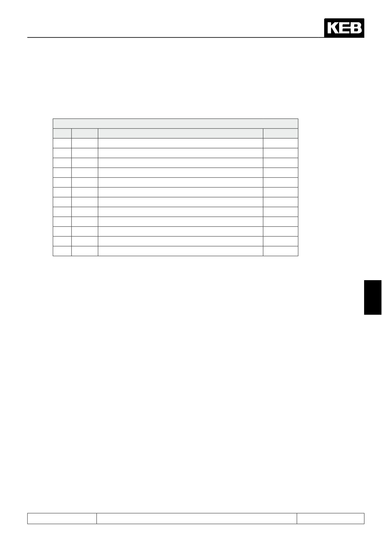
The adjustment via terminal strip can be made binary-coded or input-coded. The inputs are defined with pa-
rameter Fr.07. With binary-coded set selection maximally 3 inputs should be programmed to set selection to
avoid set selection errors.
Fr.10: Load mot. dependent parameter
Bit
Value
Input
Terminal
0
1 1)
ST (prog. input „control release/reset“)
X2A.16
1
2
RST (prog. input „reset“)
X2A.17
2
4
F (prog. input „forward“)
X2A.14
3
8
R (prog. input „reverse“)
X2A.15
4
16
I1 (prog. input 1)
X2A.10
5
32
I2 prog. input 2)
X2A.11
6
64
I3 (prog. input 3)
X2A.12
7
128
I4 (prog. input 4)
X2A.13
8
256
IA (internal input A)
no
9
512
IB (internal input B)
no
10
1024
IC (internal input C)
no
11
2048
ID (internal input D)
no
1) The input ST is occupied by hardware means with the function „Control release“. Further functions can be
adjusted only „additionally“.
Example
7
For input-coded set selection (Fr.02=3) I1, I2 and F are defined for set selection.In this case F = set1; I1 =
set2 and I2 = set3 would be acticated as the valence is (I2>I1>F). If I1 and I2 are triggered simulateously the
inverter switches into set2 since the priority is F>I1>I2 at Fr.02=3.
Binary-coded set selection
With binary-coded set selection
-
maximally three of the internal or external inputs may be programmed to set selection (23=8 sets) to
avoid set selection errors.
-
the valence of the inputs programmed for set selection rises
(ID>IC>IB>IA>I4>I3>I2>I1>R>F>RST>ST)
Page7.14 - 9
Parameter Sets
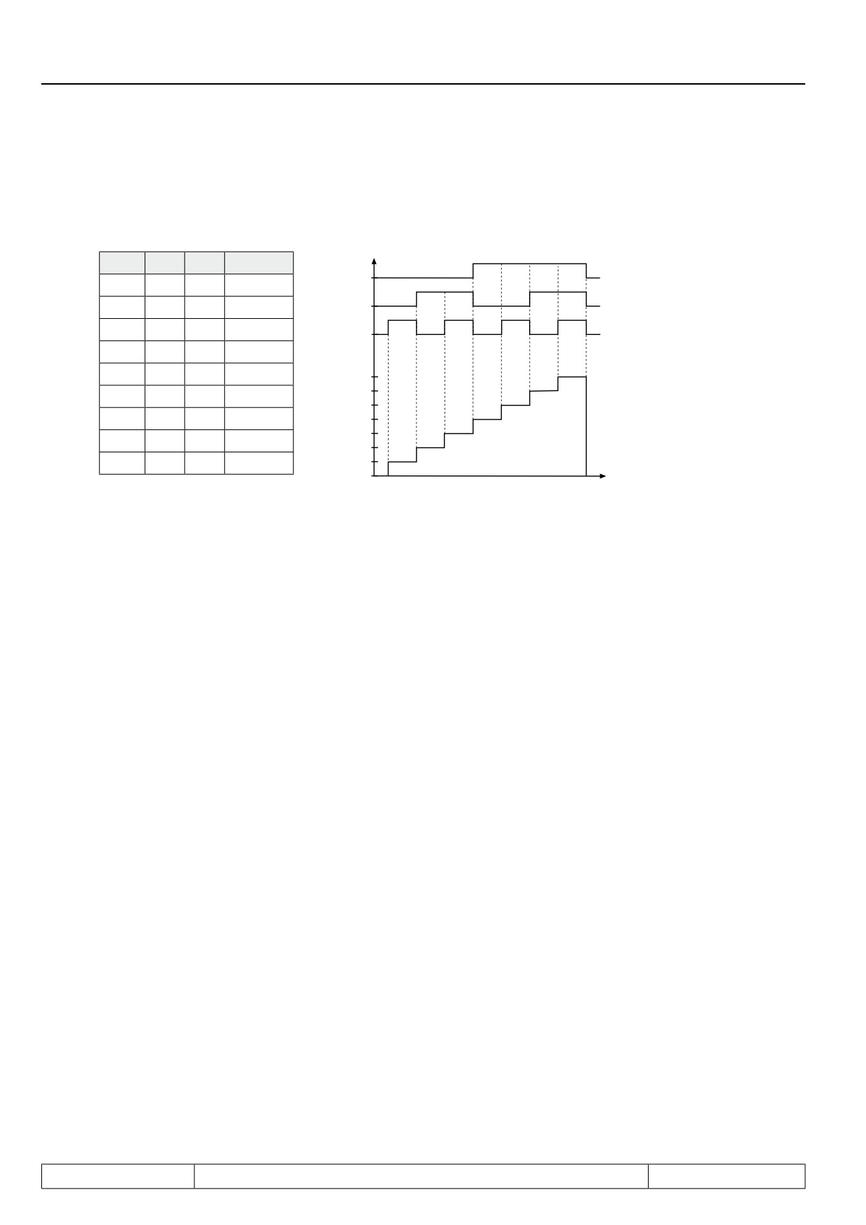
Example 1: With 3 inputs (F, I1 and I4) set 0...7 shall be selected
1.)
Adjust parameter Fr. 07 to value „148“
2.)
Adjust Fr.02 to value „2“ (set selection binary-coded via terminal strip)
I4
I1
F
Input
I4
2²
21
20
set
0
0
0
0
I1
0
0
1
1
F
0
2
0
2
Set 7
0
2
1
3
Set 6
4
0
0
4
Set 5
4
0
1
5
Set 4
Set 3
4
2
0
6
Set 2
4
2
1
7
Set 1
Set 0
t
Input-coded set selection
With input-coded set selection
-
maximally 7 of the internal or external inputs may be programmed to set selection (0...7
sets) to avoid set selection errors.
-
the lowest of the selected inputs has priority at Fr.02 = „3“
(ST>RST>R>F>I1>I2>I3>I4>IA>IB>IC>ID)
-
the highest of the selected inputs has priority at Fr.02 = „4“
(ID>IC>IB>IA>I4>I3>I2>I1>R>F>RST>ST)
Page7.14 - 10
Parameter Sets
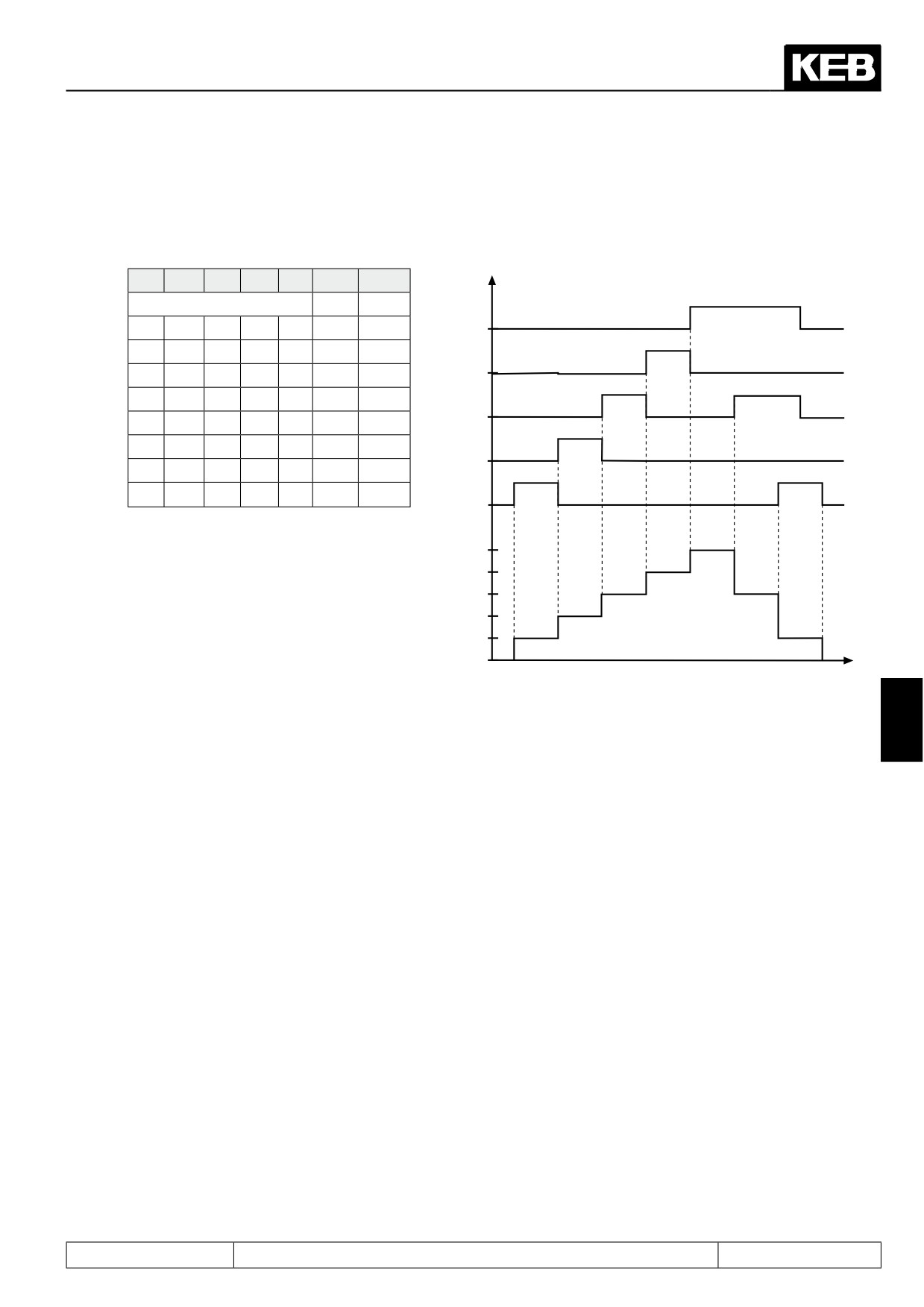
Example 1: With 5 inputs (I1, I2, I4, IB and ID) set 0...5 shall be selected.
1.)
Adjust parameter Fr. 07 to value „2736“
2.)
Adjust Fr.02 to value „3“ (set selection input-coded via terminal strip)
Id
IB
I4
I2
I1
set
set
Fr.02 =
3
4
0
0
0
0
0
0
0
ID
0
0
0
0
1
1
1
0
0
0
2
0
2
2
IB
0
0
3
0
0
3
3
I4
0
4
0
0
0
4
4
5
0
0
0
0
5
5
I2
5
0
3
0
0
3
5
5
0
3
0
1
1
5
I1
set
5
set
4
set
3
set
2
set
1
set
0
Reset set input selection (fr.11)
7
The parameter Fr.11 defines an input, with which one can switch independently of the current parameter set in
to parameter set 0. This function is only active at Fr.02 = 0...4.
-
with static input assignment the inverter remains in set 0 as long as the input is set.
-
with edge-triggered inputs set 0 is always activated with the 1st edge. With the 2 nd edge the set activa-
ted by the other inputs is selected again.
Page7.14 - 11
Parameter Sets
Set change mode modulation on (Fr.12)
Parameter Fr.12 adjusts the behavior at set change. A motor set change without parameter set changes is only
possible when the modulation is switched off.
If the set change is disabled and the modulation is switched on, then a planned set change releases the errror
‘set selection error‘ (E.SET, A.SET). The set change is done, as soon as the modulation is switched off.
Fr.12: Set change mode mod. on
Bit
Meaning
Value
0
Set change mode
0: enable / 1: inhibited
1
Mode motor set change
0: enable / 1: inhibited
Bit 1 has no function at F5-S, since only one motor set is available here.
7.14.8Locking of parameter sets
Fr.03 Parameter set lock
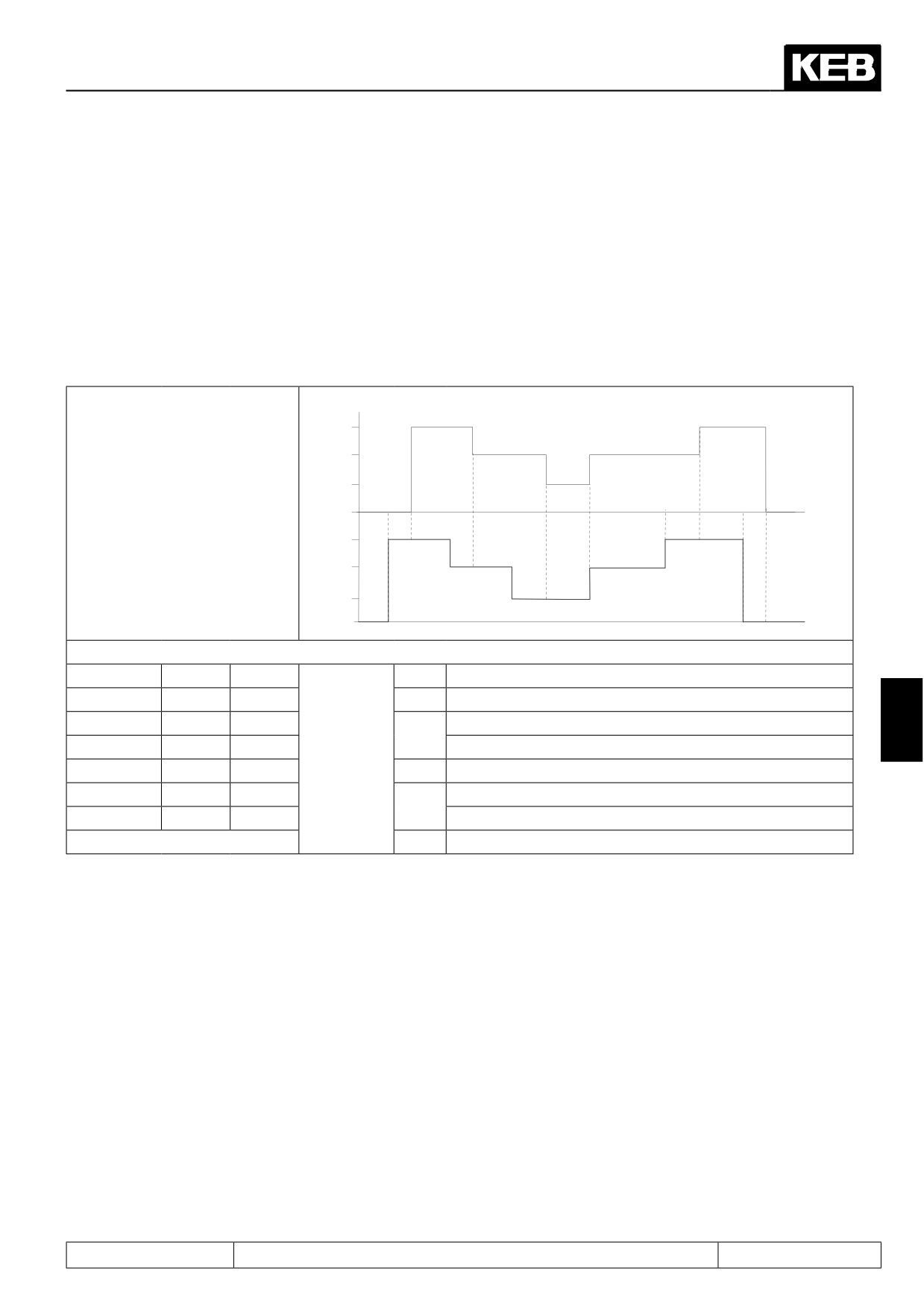
Parameter sets, that shall not and must not be selected, can be locked with Fr.03. If one of the locked sets is
selected, the adjusted response in Pn.18 is executed (default: set selection error (E.SEt).
Value
Locked set
Example (set 2 and 5 inhibited)
1
0
-
2
1
-
4
2
4
8
3
-
16
4
-
32
5
32
64
6
-
128
7
-
Sum 36
Page7.14 - 12
Parameter Sets
7.14.9Parameter set ON/OFF delay (Fr.05, Fr.06)
With these parameters the time is adjusted,
- with which the activation of a new set is delayed (Fr.05)
- with which the deactivation of an old set is delayed (Fr.06)
In the case of set changeover the OFF time of the old set and ON time of the new set are added up.
Picture 7.14.9 On and off delay
Set 3
Set 2
Set 1
Current set
Set 0
1
5
6
Set 3
2
Set 2
3
Adjusted set
Set 1
4
Set 0
Example
1:
ON delay for set 3 of 2s
on
off
2:
OFF delay for set 3 of 2s
set
Fr.5
Fr.6
3:
OFF delay for set 2 of 1s +
7
0
0s
0s
ON delay for set 1 of 2 s
1
2s
0s
4:
immediate changeover as no delay is adjusted
2
0s
1 s
5:
OFF delay for set 2 of 1s +
3
2s
2s
ON delay for set 3 of 2s
6:
OFF delay for set 3 of 2s
Page7.14 - 13
Parameter Sets
Page7.14 - 14
Special Functions
7.1
Operating and appliance data
1.
Introduction
7.2
Analog in- and outputs I
2.
Summary
7.3
Digital in- and outputs
3.
Hardware
7.4
Setpoint-, rotation- and ramp adjustment
Motor data and controller adjustments of the asynchronous
7.5
4.
Operation
motor
Motor data and controller adjustments of the synchronous
7.6
motor
Selection of Operating
5.
Mode
7.7
Speed control
6.
Initial Start-up
7.8
Torque display and -limiting
7.9
Torque control
7.
Functions
7
7.10
Current control, -limiting and switching frequencies
8.
Error Assistance
7.11
Speed measurement
9.
Project Design
7.12
Positioning and synchronous control
7.13
Protective functions
10. Networks
7.14
Parameter sets
11. Parameter Overview
7.15
Special functions
12. Annex
7.16
CP-Parameter definition
Page7.15 - 1
Special Functions
7.15.1
DC-braking
7.15 - 3
7.15.1.1
V/F characteristic control
7.15 - 5
7.15.1.2
Speed-controlled operation without feedback (ASCL)
7.15 - 5
7.15.2
Energy Saving Function
7.15 - 5
7.15.3
Motorpoti Function
7.15 - 6
7.15.4
Timer and Counter
7.15 - 9
7.15.5
Brake Control
7.15 - 12
7.15.5.1
Brake control mode
7.15 - 13
7.15.5.2
Monitoring of the brake control
7.15 - 13
7.15.5.3
Sequence of the brake control
7.15 - 14
7.15.5.4
Brake control / vector controlled
7.15 - 15
7.15.5.5
V/F characteristic controlled operation
7.15 - 17
7.15.6
Wobbel function
7.15 - 18
7.15.7
Diameter correction
7.15 - 20
7.15.8
Analog Setting of Parameter Values
7.15 - 21
Page7.15 - 2
Special Functions
7.15
Special functions
The following section should facilitate the adjustment and programming of special functions.
7.15.1DC-braking
The DC braking is available:
-
in software type F5-A (standard software), for V/F characteristic control of asynchronous motors (control
type F5-M and cS.00/ control mode < 4)
-
in software type F5-H in vector controlled operation of asynchronous motors without encoder feedback
(cS.01/ actual value source = "2: calculated actual value") and
-
at V/F characteristic control (cS.00/ control mode < 4)
During the DC-braking the motor is not decelerated over the ramp. The braking is done with a DC voltage and
a DC current, respectively, that is applied to the motor winding.
After activation of the DC braking, the modulation is switched off and the base-block time (base-block time,
duration dependent on the power circuit) waited for until the DC value is applied to the motor.
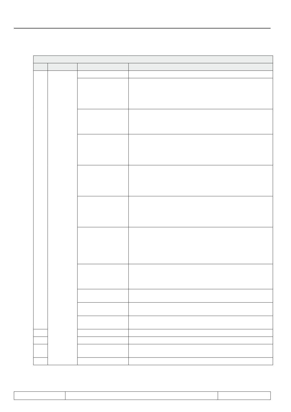
With Pn.28 one adjusts through what the DC-brake is triggered. According to the adjusted mode one can preset
with Pn.32 the speed from which the DC-brake is triggered.
Pn.30 "DC braking time" determines the braking time (0..100,00 s).
Pn.29 is bit-coded and defines the inputs which trigger DC-braking.
7
Page7.15 - 3
Special Functions
Pn.28: DC braking mode
Bit
Meaning
Value
Explanation
0: no DC braking
DC braking is never triggered
DC braking, if the setpoint reaches 0 U/min according to the ramp
1: no direction of rota-
generator (ru.02 "Ramp output display") and the rotation setting is
tion and actual value
missing. The braking time is determined by Pn.30 (independent of
= 0
the actual speed). If the rotation setting is applied again, the DC
braking is aborted.
DC braking after removal of the rotation setting. The braking time
2: disabling the direc-
is dependent on Pn.30 and the actual frequency. 1, 2
tion of rotation
Re-application of the rotation setting does not abort the DC bra-
king.
DC braking as soon as the rotation setting changes (different di-
rection of rotation or no setting). The braking time is dependent on
3: Change of direction
Pn.30 and the actual frequency (ru.03).1, 2
of rotation
Re-application of the rotation setting does not abort the DC bra-
king.
DC braking if the actual frequency ru.03 2 is lower than Pn.32 "DC-
4: no direction of rota-
braking start level" and the rotation setting is missing. The braking
tion and actual value
time is dependent on Pn.30 and Pn.32 3
< Pn.32
Re-application of the rotation setting does not abort the DC bra-
king.
0..3
DC braking if the actual frequency ru.03 1 is lower than Pn.32 "DC
braking start level" and the rotation setting is missing. The braking
5: Deceleration and
time is dependent on Pn.30 and Pn.32 3
DC Braking
actual value < Pn.32
Re-application of the rotation setting does not abort the DC bra-
Mode
king.
The setpoint before the ramp generator (ru.01 "Setpoint display)
is smaller than Pn.32 "DC-braking start level". The braking time is
1, 2
dependent on Pn.30 and the actual frequency (ru.03).
6: Setpoint < Pn.32
To leave the status "22: Standstill after DC-braking" , ru.01 must
be greater than Pn.32 + LE.16 "freq/speed hysteresis". An incre-
ase of the setpoint does not abort the DC braking.
DC braking, as soon as an input programmed to the DC-brake
7: Digital input time-
(Pn.29) is active. The braking time is dependent on Pn.30 and the
limited
actual frequency (ru.03). 1, 2
restart only after the input is deactivated.
8: as long as the digi-
DC-braking as long as an input programmed to DC-braking is ac-
tal input is set
tive.
9: at start of the mo-
DC-braking after enabling the modulation (direction of rotation +
dulation
control release) for the time Pn.30.
DC braking according to the conditions programmed in bit 4..7.
10: Conditions
The braking time is equal to Pn.30 "DC-braking time"
4
16: DCB after nop
DC braking after status "0: no control release" 4
5
32: DCB at switch on
DC braking after power-on-reset (power on) 4
64: DCB for auto-
6
DC braking after automatic restart 4
retry
7
128: DCB after LS
DC braking after status "70: standstill" 4
Page7.15 - 4
Special Functions
1
The braking time is dependent on the actual frequency (ru.03), not on the actual speed (ru.07). The re-
ference value for the calculation of the braking time, however, is a speed (dependent on ud.02 "Control
type", for "4: F5-M / 4000 rpm" the reference value is 1000 rpm). To calculate the braking time, the actual
frequency (ru.03) must therefore be converted to a speed according to the following formula:
ru.03 * 60
———————————
pole-pair number of the
motor
2
Actual braking time = Pn.30 * ru.03 * 60 / pole-pair number of the motor / reference value (The reference
value is dependent on ud.02 "Control type". In 4000 rpm-mode, the reference value is 1000 rpm, in 8000
rpm-mode, 2000 rpm, etc.)
3
Actual braking time = Pn.30 * Pn.32 / reference value (The reference value is dependent on ud.02 "Con-
trol type". In 4000 rpm-mode, the reference value is 1000 rpm, in 8000 U/min-mode, 2000 rpm, etc.)
4
These adjustment are operative only if in Bit 0...3 "DC-brake mode" the value "10: conditions" is chosen.
If the same condition is also set for speed search, DC-brake has priority.
7.15.1.1
V/F characteristic control
In V/F characteristic control, a DC voltage is applied to the motor. With Pn.31 "DC braking max. voltage", the
max. braking voltage is set.
The current is limited only by the inverter. If the inverter is oversized compared to the motor, the maximum bra-
king voltage (Pn.31) must be decreased to avoid overheating of the motor.
At large ratings the maximum braking voltage can lead to overcurrent errors (E.OC). In that case reduce it with
Pn31.
7.15.1.2
Speed-controlled operation without feedback (ASCL)
7
In ASCL-mode, a DC current is impressed on the motor.
With Pn.33 "DC braking max. current ASCL", the braking current is set. The current can be predefined in a
range of 0...400.0% with respect to the rated motor current (dr.00).
The current is limited above by the permissible standstill current (see technical data of the corresponding inver-
ter) or, if in dS.03 the maximum current mode is activated, by dr.37 "Maximum current". The lower limit is given
by the magnetising current.
After completion of the DC braking function, the rated flux of the machine must flow before the motor is started.
To that end, "Wait for magnetisation = 128: on" (Bit 7 = 1) must be programmed in Parameter dS.04 . The torque
display is not valid in the DC braking (display always = 0 Nm).
7.15.2Energy Saving Function
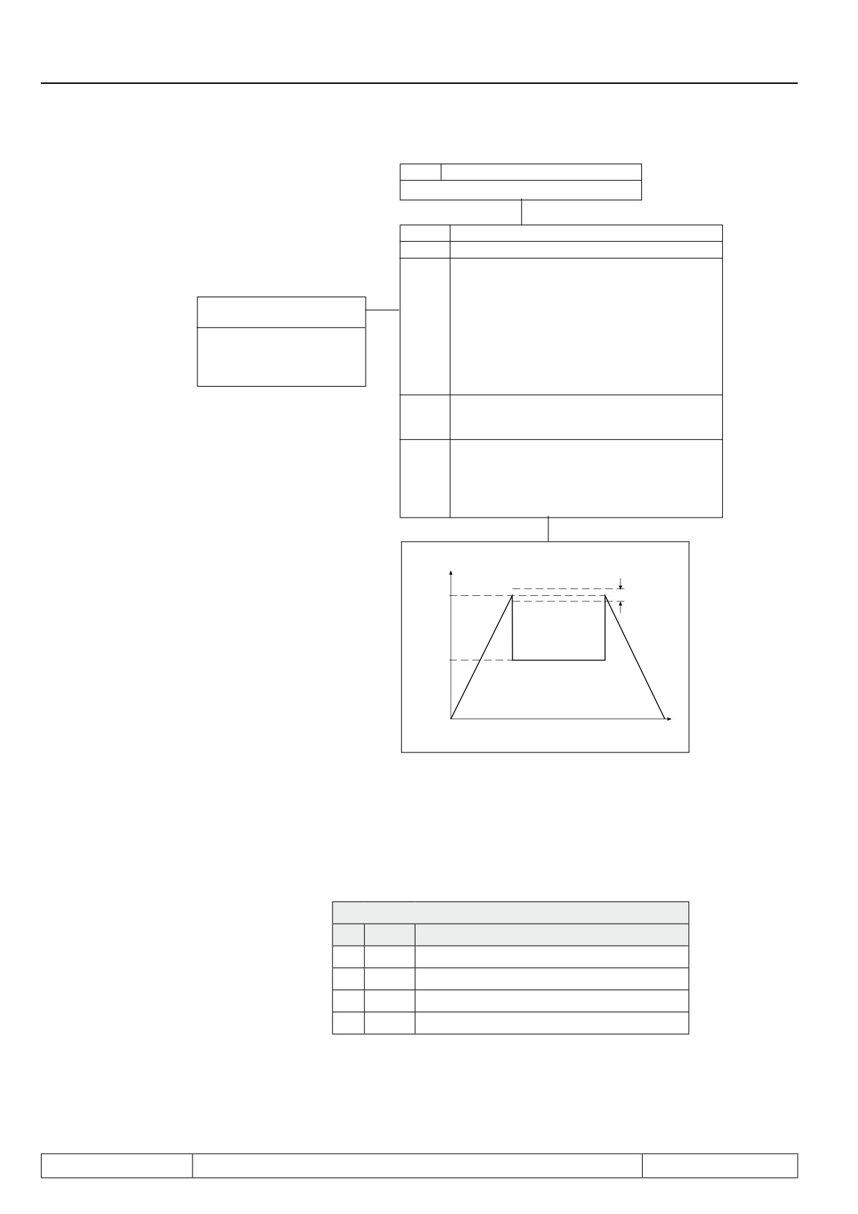
The energy saving function allows the lowering or raising of the current output voltage. In accordance with the
activation conditions defined in uF.6, the voltage valid according to the V/Hz-characteristic is changed in per-
cent onto the energy saving level (uF.07).
However, the maximal output voltage cannot be higher than the input voltage even if the value is > 100 %. The
function is used for example in cyclic executed load/no-load applications. During the no-load phase the speed
is maintained, but energy is saved as a result of the voltage reduction.
Page7.15 - 5
Special Functions
uF.07
Energy saving factor
0,0…130,0 % (default 70 %)
uF.06
Energy saving mode
Bit 0...3
Energy saving function / activation
0
generally off
1
generally active
2
at actual value = setpoint
uf.08
Energy saving input
3
by digital input
selection
4
at clockwise rotation
5
at counter clockwise rotation
0...4095 (Default 0)
also see 7.3
6
by constant run clockwise rotation
"Digital inputs"
7
by constant run counter clockwise rotation
8...15
reserved
Bit 4...6
Energy saving function / ramp time
Default time ca. 1,6 s
0
Default time
16
Default time / 2
32
Default time / 4
48
Default time / 8
64
Default time / 16
factual ; nactual; UA
Hysteresis
fset ; nset
uF.7
t
Example: uF.6 = 2, uF.7 = 50 %
7.15.3Motorpoti Function
This function simulates a mechanic motor potentiometer. Over two inputs the motor potentiometer value can
be increased or decreased.
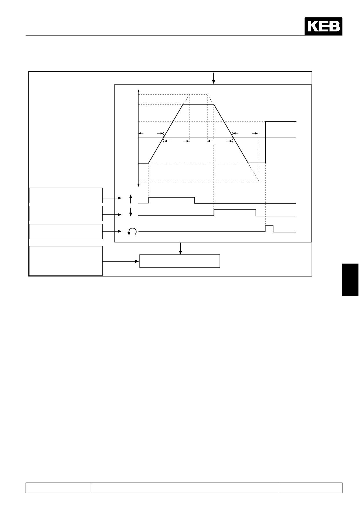
Fig. 7.15.3
Motorpoti function
oP.50: Motorpoti function
Bit
Value
Meaning
0
0
Value is changed in the current set
1
Value is changed only in set 0
1
0
no motorpoti reset after power on
1
Reset to oP.55 after power on
Page7.15 - 6
Special Functions
100%
oP.54
oP.55
oP.59
oP.59
0%
t
oP.59
oP.59
oP.53
-100%
oP.56 Increase motor poti value
input selection
oP.57 Decrease motor poti value
input selection
oP.58 Reset on oP.55
input selection
oP.52 Motor poti / Value
Input selection
ru.37 Motor poti act. value
Setting via parameter
-100...0...100%
± 100%
(oP.59 is being ignored)
7
Determine inputs (oP.56...oP.58)
In the first step two inputs must be defined with which the motor potentiometer can be increased or decreased.
For that purpose one input each according to the input table is assigned to the parameters oP.56 and oP.57. If
both inputs are triggered simultaneously, the potentiometer value is decreased.
Increase motorpoti
Decrease motorpoti
value
value
↓
↓
oP.56
oP.57
Another input (oP.58) can be used to reset the motor potentiometer to the adjusted reset value oP.55.
Page7.15 - 7
Special Functions
Input table
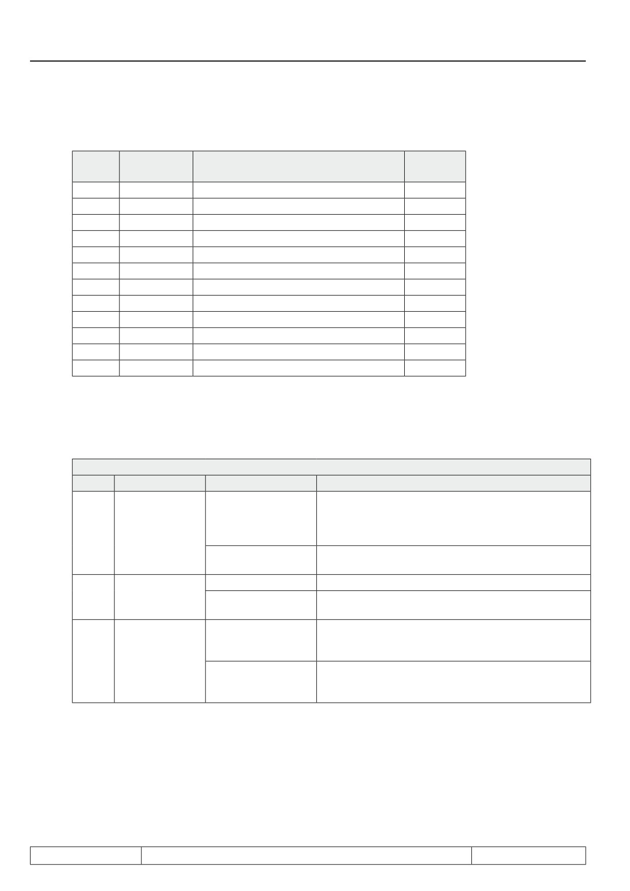
Bit -No.
Decimal
Input
Terminal
value
0
1
ST (prog. input "control release/reset")
X2A.16
1
2
RST (prog. input "reset")
X2A.17
2
4
F (prog. input "forward")
X2A.14
3
8
R (prog. input "reverse")
X2A.15
4
16
I1 (prog. input 1)
X2A.10
5
32
I2 prog. input 2)
X2A.11
6
64
I3 (prog. input 3)
X2A.12
7
128
I4 (prog. input 4)
X2A.13
8
256
IA (internal input A)
no
9
512
IB (internal input B)
no
10
1024
IC (internal input C)
no
11
2048
ID (internal input D)
no
Motorpoti function (oP.50)
The basic working method of the motor potentiometer is defined with oP.50. The parameter is bit-coded.
oP.50: Motorpoti function
Bit
Meaning
Value
Explanation
Motor potentiometer value is changed in the active para-
meter set (displayed in ru.26). Functions using the motor
Target set of the
0: Act. set (ru.26)
potentiometer value work with the value of the current
0
motor potentio-
set.
meter value
Motor poti value is changed in set 0 Functions using the
1: Set 0
motor potentiometer value work with the value of set 0.
0: no reset
Motor potentiometer value remains stored on power off
Reset at switch
1
Motor potentiometer value is written to the value of oP.55
on
2: Reset to oP.55
"Motor potentiometer reset value" in all set on power on
The adjustment of the motor potentiometer value occurs
0: Set 0
with the value of oP.59 "Motor potentiometer inc/dec time"
Source of the
from set 0.
2
ramp time
The adjustment of the motor potentiometer value occurs
4: Act. set (ru.26)
with the value of oP.59 "Motor potentiometer inc/dec time"
from the active set
Motorpoti inc / dec time (oP.59)
With this parameter a time is defined, which the motor potentiometer needs in order to run from 0...100%. The
time is adjustable between 0...50000 s.
Page7.15 - 8
Special Functions
Control range (oP.53, oP.54)
The correcting range is limited by the parameters oP.53 "Motor poti min. value" and oP.54 "Motor poti max.
value" (see Fig. 7.15.3).
Display of motor potentiometer value (ru.37)
This parameter shows the current value of the motor potentiometer in percent.
Motor potentiometer value (oP.52)
A percentage value can be set directly by operator or bus via this parameter. The ramp time remains unconsi-
dered at this setting.
The parameter value is limited by oP.53 / oP.54. If a digital input is set for increasing or decreasing the motor
potentiometer value, the value of oP.52 changes.
7.15.4Timer and Counter
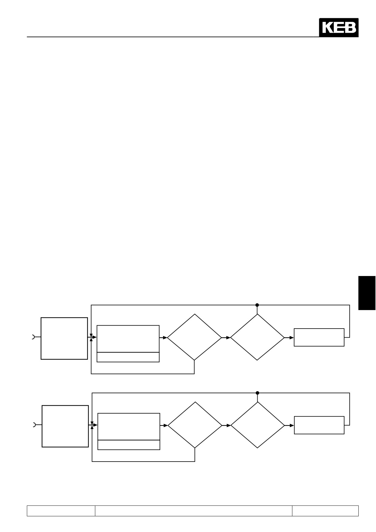
Two timers are incorporated in the COMBIVERT. As long as one of the adjustable starting conditions (LE.18/23)
or a programmable input (LE.17/22) is set, the timer counts until reaching the final range value. If one of the re-
set conditions (LE.20/25) is fulfilled or one programmable input (LE.19/24) is set, the timer jumps back to zero.
The clock source and the counting direction is adjusted with LE.21/26. It can be counted in seconds, hours or
by a special programmed input for that. The current timer content is displayed in ru.43/44. On reaching an ad-
justable comparison level (LE.00...07), the switching condition 37/38 is set. It can be used to set an output.
Fig. 7.15.4
Timer programming
7
continues to count
no
Is a
Timer counts up to maximum
Reset condition
Switching condition
LE.21 Timer 1 /
value; down to 0, if a condition
no
yes
of LE.20 or LE.19
Timer value > Level
37 "Timer 1 > Level A"
I3
Mode
of LE.18 is fulfilled or an input
fulfilled ?
LE.0...LE.7 ?
is being set!
of LE.17 is set
ru.43 Timer 1 Display
yes
Resetting to zero
continues to count
no
Is a
Timer counts up to maximum
Is a reset
no
yes
Switching condition
LE.26 Timer 2 /
value; down to 0, if a condition
condition of
Timer value > Level
38 "Timer 2 > Level A"
I4
Mode
of LE.23 is fulfilled or an input
LE.25 or LE.24
LE.0...LE.7 ?
is being set!
of LE.22 is set
fulfilled ?
ru.44 Display timer 2
yes
Resetting to zero
Timer mode (LE.21 / LE.26)
Page7.15 - 9
Special Functions
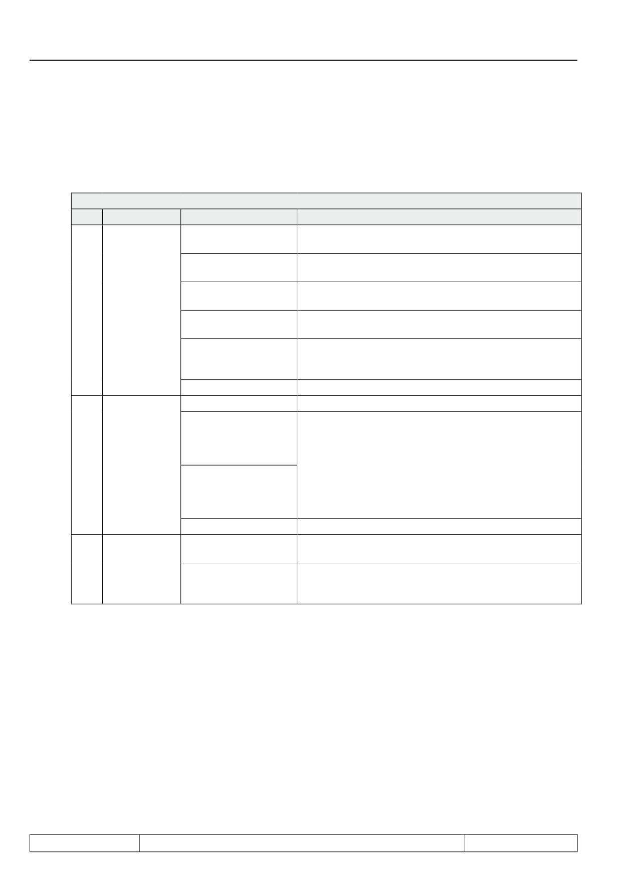
LE.21 and LE.26 determine the clock source and the counting direction of timer 1 and 2. Clock pulse source can
be the time counter in 0.01s or 0.01h grid, pulses from a digital input, or revolutions of the encoder on encoder
channel 1. The timer runs generally as long as a starting condition is active. After a reset the timer starts again
at zero. Following clock sources can be selected:
LE.21 / LE.26: Timer 1 / 2 mode
Bit
Meaning
Value
Explanation
0: 0,01s (internally
The timer value increases / decreases every 10 ms by 0.01
clock)
1: 0,01h (internally
The timer value increases / decreases every 36s by 0.01
clock)
2: every edge T1-I3 /
Each edge on I3 (for timer 1) or I4 (for timer 2) increases /
Selection clock
T2-I4
decreases the timer value by 0.01
0...2
pulse source
3: positive edge T1-I3
A rising edge on I3 (for timer 1) or I4 (for timer 2) increases /
/ T2-I4
decreases the timer value by 0.01
Each revolution (clockwise rotation and counter clockwise
4: Rotation encoder 1
rotation) of the encoder on channel 1 increases / decreases
the timer value by 0.01
5...7: reserved
0: upward
The counting direction of the timer is always upwards
8: Dependent on the
actual speed FOR =
upward
Counting
REV=downward
The counting direction of the timer is dependent on the cur-
3,4
direction
16: Dependent on the
rent direction of rotation
actual speed FOR =
downward
REV = upward
24: reserved
The timer stops on reaching the maximum value of 655.35 or
0: Stop at limit
the minimum value of 0
Overflow be-
5
The timer always runs through. After reaching of the maxi-
haviour
1: Reset and further
mum value (655.35) the timer starts again at 0. After reaching
of the minimum value (0) the timer starts again at 655.35.
Timer start condition (LE.18 / LE.23)
Page7.15 - 10
Special Functions
From the following table the conditions can be selected at which the timer is started. The individual conditions
are OR-operated with the Timer start input selection (LE.17/LE.22).
LE.18 / LE.23: Timer 1 / 2 start condition
Bit
Value
Timer / Starting condition
0
1
Modulation on
1
2
Modulation off
2
4
Actual freq. =setpoint freq.
3
8
Modulation off and no power on
In case of several starting conditions the values are to be added up.
Timer start input selection (LE.17 / LE.22)
Additionally the timer can be activated by one or several inputs. The sum of the valences is to be entered, if
the timer shall be started by different inputs The individual inputs are OR-operated. The start input selection is
OR-operated with the timer / starting condition (LE.18/LE.22).
Bit
Value
Input
Terminal
0
1
ST (prog. input "control release/reset")
X2A.16
1
2
RST (prog. input "reset")
X2A.17
2
4
F (prog. input "forward")
X2A.14
3
8
R (prog. input "reverse")
X2A.15
4
16
I1 (prog. input 1)
X2A.10
7
5
32
I2 prog. input 2)
X2A.11
6
64
I3 (prog. input 3)
X2A.12
7
128
I4 (prog. input 4)
X2A.13
8
256
IA (internal input A)
no
9
512
IB (internal input B)
no
10
1024
IC (internal input C)
no
11
2048
ID (internal input D)
no
Timer display (ru.43 / ru.44)
ru.43 / ru.44 displays the actual counter reading dependent of the adjusted clock source (LE.21 / 26). By wri-
ting on ru.43 / 44 the counter can be set to a value. If the clock source is changed during the running time the
counter content is maintained but is interpreted according to the new clock source.
Timer reset input selection (LE.19 / LE.24)
According to the following table the inputs with which the timer is reset can be specified. The individual inputs
are OR-operated, i.e. if one of the specified inputs is triggered, the timer jumps back to zero. If a starting and
reset condition are active simultaneously, reset has priority.
(see table "Timer start input selection (LE.17 / LE.22)")
Page7.15 - 11