KEB COMBIVERT F5-A,-E,-H 4.0. APPLICATION MANUAL (2008) - page 19
Protective Functions
7.13.1.1
Undervoltage
"Error! Undervoltage" (E.UP) is triggered if the DC link voltage drops due to brownouts or a generally too weak
power grid. For this error, the automatic restart can be activated.
Error phase loss
"Error! Phase loss" (E. UPh) is identified indirectly via the ripples in the DC link voltage.
If one power phase is missing, the waviness in the DC link is considerably increased under load. In no-load
operation or at small load, the error of the power phase is, however, not recognised. For this error, an automatic
restart cannot be programmed.
7.13.1.2
Overvoltage
"Error! Overvoltage" is triggered if the DC link voltage increases beyond the overvoltage level due to energy
recovery in generator operation.
7.13.1.3
Overcurrent
The "Error! Overcurrent" (E.OC) is trigger when the "OC-tripping current" (see technical data in the instruction
manual power circuit F5) is exceeded.
If this error occurs permanently, either the connected motor (short circuit or ground fault) or the inverter itself
is defective.
Below the overcurrent limit lies the "maximum short time current limit". If this is exceeded, the hardware current
limit can be triggered with uF.15. The response of this function is not considered an error or malfunction, and
the corresponding switching conditions are not set. If the function is active, the status "80:hardware current
limitation active" (HCL) is displayed.
For current regulated drives, this function should be deactivated since it may have negative effects for the motor
model calculation and the behaviour of the drive.
7.13.1.4
Overload
The inverter-overload protection is a function that triggers an error for which, however, a pre-warning can be
generated.
There are two overload protection functions: one for the range of standstill and low frequencies (overload at
standstill/ OL2) and one for the remaining frequency range (overload/ OL).
With Pn.9 "Overload warning level" a value between 0...100 % can be adjusted, for which the "Warning! Over-
load" and the "Warning! Overload during standstill", respectively, is set. The response to the overload warning
is set with Pn.8 "overload warning response".
Overload in the standstill (OL2)
The implementation of the function "19: Overload during standstill" is described in chapter 2.1.9 "Overload
protection in the lower speed range". The motor current is guided via a PT1 link with a time constant of 280 ms.
If this delayed current exceeds the OL2 limit, "Error! Overload during standstill" (E.OL2) is triggered. If the dela-
yed current decreases to 0 again, the inverter enters the status "20: Overload during standstill fixed" (E.nOL2).
The error can now be reset.
Page7.13 - 4
Protective Functions
Overload (OL)
The implementation of the general overload protection is described in chapter 2.1.8 "Overload characteristics".
If the 100% load factor of the inverter is exceeded by 5 %, the internal overload counter starts to count forward.
If the load factor falls below 100 %, the counter counts backward. The current counter content can be read in
parameter ru.39. Upon reaching 100 % the inverter switches off with error message "E.OL" and the counter
counts backward. If it reaches 0 %, the status changes to E.nOL and the error can be reset.
7.13.1.5
Inverter over temperature
Heat sink overtemperature
The heat sink temperature acquisition protects the power module from thermal overload. The temperature at
which the inverter switches off with error message "8: ERROR! Overtemperature" (E.OH) depends on the po-
wer circuit (generally 90°C).
After cooling period the status changes from "Error! Overtemperature" to "36: Heat sink temperature normal
again" (E.nOH) and is therefore resettable.
With Pn.11 "OH warning level" a level of between 0° C and 90 °C can be set, at which the pre-warning is trig-
gered. The response to the warning message is set with Pn.10 "Warning OH stopping mode".
Internal overtemperature
The interior temperature monitoring protects the inverter against malfunctions caused by too high temperature
in the interior of the inverter. Upon exceeding a unit-specific temperature the interior fan is activated. If the tem-
perature is still too high after about 10 min., the disconnecting time set with Pn.17 "E.OHI delay time" (0...120s)
starts.
With the start of the disconnecting time, switching condition "11: Warning internal overheating" is met and the
response to the warning message set in Pn.16 "Wrning OHI stopping mode" is executed.
7
After expiration of the disconnecting time, "6: ERROR! Overtemperature interior" (E.OHI) is triggered.
When the interior temperature has dropped again, the inverter state changes again to "7: interior temperature
back to normal" (E.nOHI). The error can now be reset.
7.13.1.6
External fault
With Pn.04 "Ext. fault input selection", one or more digital inputs can be programmed which can trigger the error
"31: ERROR! External input" (E.EF).
With Pn.03 "E.EF stopping mode" , the response of the inverter to the digital input is defined. With Pn.65/ bit
1 "2: Pn.04 = E.UP", the function of Pn.04 can be changed and the triggering of an error via a digital input can
be deactivated.
7.13.1.7
Bus error
The inverter contains two watchdogs that monitor the communication between an external bus, the operator,
and the inverter control.
With parameter Pn.05 "E.buS stopping mode", the response to a watchdog error is defined. Dependent on
the chosen adjustment, either "Error! Watchdog" (E.buS) or "Warning! Watchdog error" (A.buS), is issued or a
warning message via a digital output is generated.
Page7.13 - 5
Protective Functions
Watchdog time (Pn.06)
This watchdog monitors the communication at the operator interface. With an activated watchdog, the response
set under Pn.05 is triggered after expiration of an adjustable time (0.01...40 s) without received telegrams.
By setting the value to "0:off", the function is deactivated.
HSP5 Watchdog time (SY.09)
The HSP5 Watchdog function monitors the communication of the HSP5 interface (control card - operator; or
control card - PC). After expiration of an adjustable time (0,01...10 s) without incoming telegrams, the response
adjusted in Pn.5 is triggered. The value "0:off" deactivates the function.
7.13.1.8
Limit switch error
Hardware limit switch
The inputs occupied with the functions "32: forward" (limit switch right) and"64: backward" (limit switch left)
serve as hardware limit switches. Therefore, the rotation setting via terminals (oP.01 "rotation source" = 2...6)
may not be used if the limit switch function is to be used.
To protect against cable breakage, an unconnected input means that the drive has run onto the limit switch.
Depending on the setting of parameter Pn.07 "Proh. rotation stopping mode", the response to the hardware
limit switches can be a malfunction or an error.
Hitting a limit switch with clockwise direction of rotation is indicated by status "46: ERROR! disabled direction of
rotation clockwise" (A.PrF) and:94 ABN. disabled direction of rotation clockwise" (A.PrF), respectively. The cor-
responding messages for counter clockwise direction of rotation are "47: ERROR! disabled direction of rotation
counter clockwise" (A.PrF) and:95 ABN. disabled direction of rotation counter clockwise" (A.Prr), respectively.
Attention: Only the limit switch for the current direction of rotation is ever evaluated, i.e., for clockwise rotation,
only the right limit switch is considered and the left limit switch is ignored. The analog applies to counter clock-
wise rotation.
Furthermore, one must ensure that the drive stops at the limit switch. If the limit switch is overrun, the drive can
subsequently continue to run in the disabled direction.
Software limit switch
The software limit switches complement the function of the hardware limit switch.
They are active only after an approach to reference point or the setting of reference points, respectively (see
chapter 7.12.2 approach to reference point).
In contrast to hardware limit switches, the software limit switches can lose their protective function by, e.g., a
faulty approach to reference point. Their advantage is that they cannot be overrun.
The permissible range of the actual position ru.54 lies between PS.15 "limit switch left" and PS.16 "limit switch
right"
The software limit switches are active in the vector controlled operation, in synchronous mode, in positioning
mode, or in contouring mode.
The response to the software limit switch is set in parameter Pn.66 "software limit stopping mode" . In the fac-
tory setting, the software limit switches are deactivated.
Reaching the limit switch with clockwise direction of rotation is indicated by status "44: ERROR! Software limit
switch clockwise rotation" (E.SLF) and "104: ABN. Software limit switch clockwise rotation" (A.SLF), respec-
tively. The corresponding messages for counter clockwise direction of rotation are "45: ERROR! Software limit
switch clockwise rotation" (E.SLF) and "105: Software limit switch counter clockwise rotation" (A.SLr), respec-
tively.
Page7.13 - 6
Protective Functions
7.13.1.9
Motor protection with temperature sensor
The motor can be protected from thermal destruction due to permanent overloading by connecting a PTC or a
KTY-sensor.
If PTC or KTY report an overtemperature, the disconnecting time set in Pn.13 "E.dOH delay time" starts. The
switching condition "9: Pre-warning motor overheating" is set and the response to the pre-warning set in Pn.12
"Warning dOH stopping mode" is executed. If a value of 1..5 is selected in Pn.12, the inverter reports the mal-
function "Warning! Motor overheating" (A.dOH).
After expiration of the disconnecting time Pn.13, the error "Error! Motor overheating" (E.dOH) is triggered.
If the overtemperature condition is past, the message "All clear! Motor overheating" (A.ndOH) or "Motor tem-
perature back to normal" (E.ndOH) is issued. Only then the error can be reset or the automatic restart can be
carried out.
7.13.1.10
Software motor protection
In addition to the monitoring of the motor with a temperature sensor, a further motor protection can be realised
by monitoring the motor current.
The monitoring function is implemented differently for asynchronous and synchronous motors.
Emulation of an electronic motor protection relay
The functional description (time, current level, etc.) are found in chapter xxx "electronic motor protection".
The response to the triggering of the electronic motor protection relay can be defined with Pn.14 "motor pro-
tection response". Dependent on the programming, the inverter raises "30: ERROR! Motor protection function"
(E.OH2) or "97: ABN. Motor protection function" (A.OH2).
After the cooling period, the error or the malfunction, respectively, can be reset.
Motor current monitoring for servo drives
7
The functional description (time, current level, etc.) are found in chapter xxx "electronic motor protection". When
the protection function triggers, the error "30: ERROR! Motor protection function" (E.dOH) is triggered. The
error is resettable after approximately 100 ms.
With Pn.15 "Motor protection function level", a level of 0...100 % (100% = triggering time of the error) can be
set at which a pre-warning is generated.
The response to the pre-warning is set with Pn.14 "Motor protection function response". With this, an abnormal
stopping can be executed before the drive raises an error. During the abnormal stopping, the inverter has status
"97: ABN. Motor protection function" (A.OH2). The switching condition "10: Motor protection relay function" is
met.
7.13.1.11
Set selection error
With Fr.03 "Parameter set lock", sets can be disabled. If a disabled set is selected, the inverter remains in the
old set, i.e., no set change occurs.
The response to the selection of a disabled set is set via Pn.18 "E.Set stopping mode". In the factory setting,
the error "39: ERROR! Parameter set selection" (E.Set) is triggered. For Pn.18 = 1...5 a malfunction "102: ABN.
Set selection error" (A.Set) is generated. For Pn.18 = "6: Function disabled", the drive continues running in the
old set without message.
Page7.13 - 7
Protective Functions
7.13.1.12
Encoder interface / encoder error
Encoder interface error
On switch on, the control checks if an encoder interface is present, and if so, which one. If an invalid encoder
identifier is read (e.g., due to EMK-malfunctions), or if the data exchange with the interface card cannot be
established, the drive reports "52: ERROR! Encoder interface" (E.Hyb).
The inverter state "59: ERROR! Interface change" (E.HybC) is displayed when the encoder interface card is
removed and replaced by a different type of interface prior to the switch on.
Encoder error
The progress message "32: ERROR! Encoder 1" (E.EnC1) or "34: ERROR! Encoder 2 (E.EnC2)" is trigger if:
•
a defective track is identified for an incremental encoder interface with monitoring of the incremental
tracks
•
for resolver interfaces, signals outside of the specifications are identified
•
for encoder types that permit the storage of data (e.g., motor data, system position, etc.) in the encoder,
an invalid identifier is read, and therefore the stored data cannot be interpreted.
For "intelligent" encoder interfaces (e.g., absolute encoder, Sin-/Cos encoder), "35: ERROR! Encoder change"
(E.EnCC) is trigger if:
•
the encoder type or the interface type of the current software of the control board are not supported
•
the signals of the absolute track or the signals of the incremental track are defective
•
the identified position deviation between incremental position and absolute position is too large
•
the encoder transmits an error message
•
the encoder (for encoder types with data storage in the encoder) was swapped
•
Adjusted increments per revolution of the inverter does not agree with the encoder increments per re-
volution
Error E.EncC can only be reset with parameter Ec.00.
!Exception! An error due to incorrect encoder increments per revolution is immediately (without Reset!) reset
if the correct encoder increments per revolution is set.
Not all monitoring functions are available for all interface types. A more detailed description of the encoder error
can be found in chapter 7.11 "Speed measurement".
7.13.1.13
Speed limit exceeded
The status "58: ERROR! Speed limit exceeded" (E. OS) is triggered when ru.07 "actual value display" exceeds
either the value of oP.40/ oP.41 "Max. output value forward / reverse" or the value of ru.79 "abs. speed value
EMK" (only for synchronous motors).
With oP.40 / oP.41, the user sets limits that may not be exceeded by the application under any circumstances.
ru.79 shows the maximum speed for a synchronous motor which, if exceeded, leads to an EMK of the motor
high enough to damage the DC-intermediate circuit of the inverter.
Reason for the occurence of excessive speed can be too small a distance between the maximum setpoint and
the speed limit, so that overshoots can trigger the error. Other causes can be (e.g., caused by EMK) malfunc-
tions in the speed measurement or a noisy, insufficiently smoothed speed estimate in the encoderless control
(SCL or ASCL).
Page7.13 - 8
Protective Functions
7.13.1.14
Speed controller limit reached
Pn.75 "Response to error E.SCL" determines how the output should respond if the speed controller reaches the
limit, i.e., if the set torque reaches the maximum possible value. In the factory setting, this operating condition
can be applied to a digital output (switching condition "53: Speed control at the limit").With Pn.75, however, it is
also possible to execute an abnormal stopping on reaching the torque limit (Status "107: ABN. Speed controller
limit"/ A.SCL) or to trigger an error (Status "25: ERROR! Speed controller limit / E.SCL)
7.13.1.15
Maximum acceleration exceeded
With Pn.79 "Acceleration limit 1/s^2", the maximum permissible acceleration is defined.
Pn.80 "Acceleration scan time" determines the time period used for acceleration averaging.
The change of the actual speed (ru.07) in this time period, divided by the scan time (Pn.80), gives the current
acceleration. For the calculation of the acceleration, the speed difference must be converted from 1/min to
1/s.
Speed change during scan time
Acceleration =
—————————————————————
60 x acceleration scan time (in seconds)
If the acceleration exceeds the limit (Pn.79), the response defined by Pn.81 "Warning acc stopping mode" is
triggered.
The drive, dependent on the programming, enters the status "24: ERROR! Maximum acceleration" (E.Acc) or
"106: ABN. Maximum acceleration" (A.Acc)
7.13.1.16
General power circuit error
7
On some inverter types, monitors for the internal hardware (e.g., fans) are integrated. If one of these monitoring
circuits reports an error, "12: general power circuit error" (E. PU) is triggered.
Page7.13 - 9
Protective Functions
7.13.2Response to malfunction messages
7.13.2.1
Selection of the response
Abnormal stopping (i.e., automatic shutdown of the drive) is possible for all errors that do not enforce immediate
shutdown of the modulation or for which pre-warnings can be generated.
If abnormal stopping is not sensible in the application, the possibility to set a digital output is available for many
malfunctions.
The response is programmable for the following malfunctions:
-
Ext. error
Pn.03
E.EF stopping mode
-
Watchdog
Pn.05
E.buS stopping mode
-
Hardware limit switch
Pn.07
proh. rot. stopping mode
-
Set selection error
Pn.18
E.Set stopping mode
-
Software limit switch
Pn.66
Software limit stopping mode
-
Speed controller limit
Pn.75
Response to error E.SCL
-
Acceleration monitoring
Pn.81
Warning acc stopping mode
Other errors switch off the modulation, but a pre-warnings can be generated prior to their triggering. In the time
between the pre-warning signal and the triggering of the error, the drive can be hut down via abnormal stopping.
The response is programmable:
-
overload
Pn.08
Warning OL stop. mode
-
Heat sink overtemperature
Pn.10
Warning OH stopping mode
-
internal overtemperature
Pn.16
Warning OHI stopping mode
The motor protection functions can be deactivated. If they are to be used, a pre-warning can be generated here
as well prior to the triggering of an error, providing time to shut down the drive.
-
motor protection
Pn.14
Warning OH2 stopping mode
-
Motor overtemperature
Pn.12
Warning dOH stopping mode
The descriptions of the errors and the corresponding pre-warning signals are contained in chapter 8.1 "Error
assistance".
Page7.13 - 10
Protective Functions
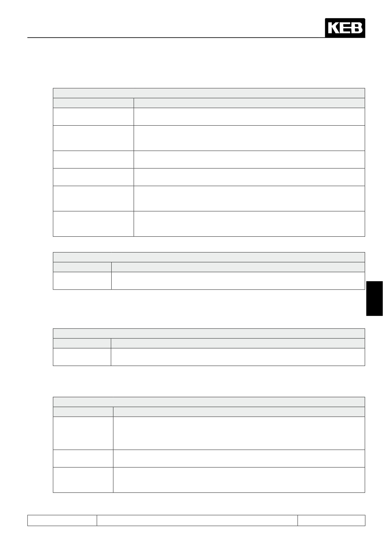
The following responses can be used for all malfunctions and errors, respectively:
Pn.03, Pn.05, Pn.07, Pn.08, Pn.10, Pn.12, Pn.14, Pn.16, Pn.18, Pn.66, Pn.75, Pn.81: Response
Value
Explanation
the malfunction turns into the error (Status: E.xx), immediate shutdown of the
0: error / no auto restart
modulation, restart only after RESET
Deceleration at the abnormal stopping-ramp or the torque- and current limit,
1: Stop / modulation off/ no
respectively, shutdown of the modulation after reaching speed 0, restart only
auto restart
after RESET
2: Stop / modulation on /
Deceleration at the abnormal stopping-ramp or the torque- and current limit, re-
no auto restart
spectively, holding torque after reaching speed 0, restart only after RESET
3: Modulation off / auto re-
Immediate shutdown of the modulation, automatic restart as soon as the mal-
start
function is resolved
Deceleration at the abnormal stopping-ramp or the torque- and current limit, re-
4: Stop / modulation off/
spectively, shutdown of the modulation after reaching speed 0, automatic restart,
auto restart
as soon as the malfunction has been resolved
Deceleration at the abnormal stopping-ramp or the torque- and current limit, re-
5: Stop / modulation on /
spectively, holding torque after reaching speed 0, automatic restart, as soon as
auto restart
the malfunction has been resolved
Pn.03, Pn.05, Pn.08, Pn.10, Pn.14, Pn.75, Pn.81: Response
Value
Explanation
6: Warning via di-
No response of the drive, the malfunction (and pre-warning, respectively ) can be issued
gital output
via a digital output
7
The response to the malfunction message limit switch error (hardware or software) and set selection error
can be switched off completely.
Pn.07, Pn.18, Pn.66: Response
Value
Explanation
6: Function swit-
the malfunction is ignored, no response of the drive, no message via digital output pos-
ched off
sible
For the malfunction "motor overtemperature", several additional choices exist:
Pn.12: Motor overtemperature response
Value
Explanation
the motor temperature is monitored, the drive does not execute an automatic abnormal
6: Warning via digi-
stop during the pre-warning period, the pre-warning message can only be issued via
tal output
a digital output. After expiration of the pre-warning period, the inverter goes to error
E.doH
Motor temperature is not monitored, the error motor overtemperature is never triggered.
7: no error
No message via digital output possible
The motor temperature is not monitored while the modulation is switched off. If the
8: no error if modu-
modulation is switched on, monitoring occurs, too. The pre-warning signal, and - after
lation is off
expiration of the pre-warning period - the error motor overtemperature is generated.
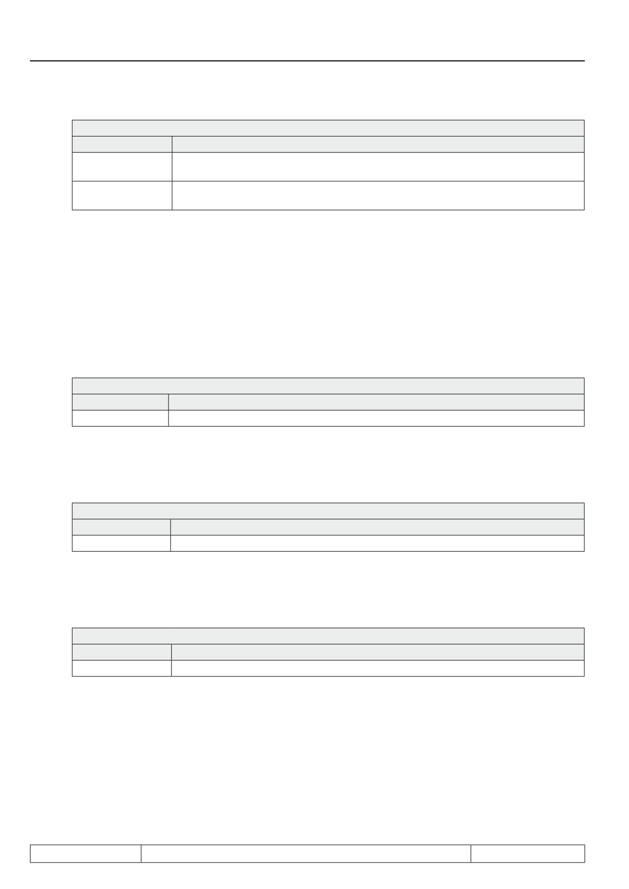
For the malfunction "internal overtemperature", there are 2 response options as well:
Page7.13 - 11
Protective Functions
Pn.16:Warning OHI stopping mode
Value
Explanation
6: Warning via digi-
The monitoring of the internal temperature is active, but the drive does not execute an
tal output
automatic abnormal stop. A pre-warning signal can be issued via a digital output
7: Error deactiva-
Monitoring of the internal temperature never triggers an error. A pre-warning signal does
ted
not exist.
7.13.2.2
Parametrisation of the abnormal stopping
The abnormal stopping-function is different for vector controlled systems (CS.00 = 4,5,6) and for systems with
V/f-characteristic-control.
Quick stop for closed-loop systems
For abnormal stopping with closed-loop systems, the drive is decelerated with the adjusted ramp time, and at
the torque limit, respectively.
Pn.60: Quick stop dec time
Value
Explanation
0..300 s
Deceleration ramp for abnormal stopping-function
For the abnormal stopping, the "normal" torque limitations of the application often do not apply since the auto-
matic shutdown is always a malfunction response. To permit a quicker deceleration with a greater torque here,
there is a unique torque limit for abnormal stopping.
Pn.61: Quick stop torque limit
Value
Explanation
0 .. 32000.00Nm
Quick stop torque limit
The torque limitation superimposed by the limiting characteristic and the available current remain in effect.
For asynchronous motors, the maximum cutoff torque for abnormal stopping can also be increased to make
more torque available for braking, even in the field weakening range.
Pn.67: Quick stop maximum torque corner speed
Value
Explanation
0 .. 32000.00Nm
the limiting characteristic for abnormal stopping is defined by dr.16 instead of Pn.67
Quick stop at open loop systems
For abnormal stopping with V/F characteristic control, the drive is decelerated with the adjusted ramp time,
and at the torque limit, respectively. Whether braking occurs at the ramp or at the current limit is defined in
parameter Pn.58.
Page7.13 - 12
Protective Functions
If no abnormal stopping is to be executed, there are various possibililty for the response, depending on the type
of malfunction.
Additionally, for most malfunctions, issuing the value 6 = warning via a digital output is possible.
Thereby, the inverter does not automatically execute an abnormal stopping. With the warning via a digital out-
put, however, an external control is given the opportunity to respond to the malfunction as is appropriate for
the application. To issue the warning message, a digital output must be programmed with the corresponding
switching condition (see chapter 7.3 Programming of the digital outputs).
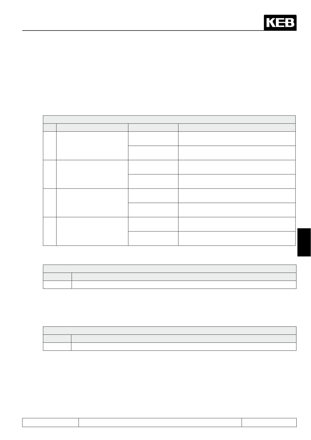
Pn.58: Quick stop mode
Bit
Meaning
Value
Explanation
Abnormal stopping at the abnormal stopping
0: Ramp generator
ramp
0
Quick stop mode (F5-G)
1: Differential con-
Deceleration time for abnormal stopping is deter-
troller
mined by means of a controller
Current limit for deceleration refers to the appa-
0: Apparent current
rent current
1
Quick stop act. value (F5-G)
Current limit for deceleration refers to the active
2: Active current
current
0: Sy.50 modulation
Shutoff of the modulation after reaching of speed
Abnormal stopping via con-
off
0 due to abnormal stopping
2
trol word (Sy.50)
4: Sy.50 modulation
Fast stop with holding torque on reaching speed
on
0
The status bit "abnormal stopping" remains active
0: Status bit on
until leaving the function
3
Status bit at standstill
The status bit "abnormal stopping" is reset when
8: Status bit off
the drive has reached standstill
7
For abnormal stopping at the ramp generator, parameter Pn.60 is the ramp time for the deceleration ramp.
Pn.60: Quick stop dec time
Value
Explanation
0..300 s
Deceleration ramp for abnormal stopping-function
For abnormal stopping with differential controller, this ramp is modified so that the drive decelerates preferably
at a
current limit.
This current limit is set in Pn.59 "abnormal stopping level".
Pn.59: Quick stop level
Value
Explanation
0 .. 200%
Current limit for deceleration = 0..200% rated inverter current (In.01)
With Pn.58 bit 1, it can be selected whether the inverter decelerates at the active current- or the apparent
current-limit.
Page7.13 - 13
Protective Functions
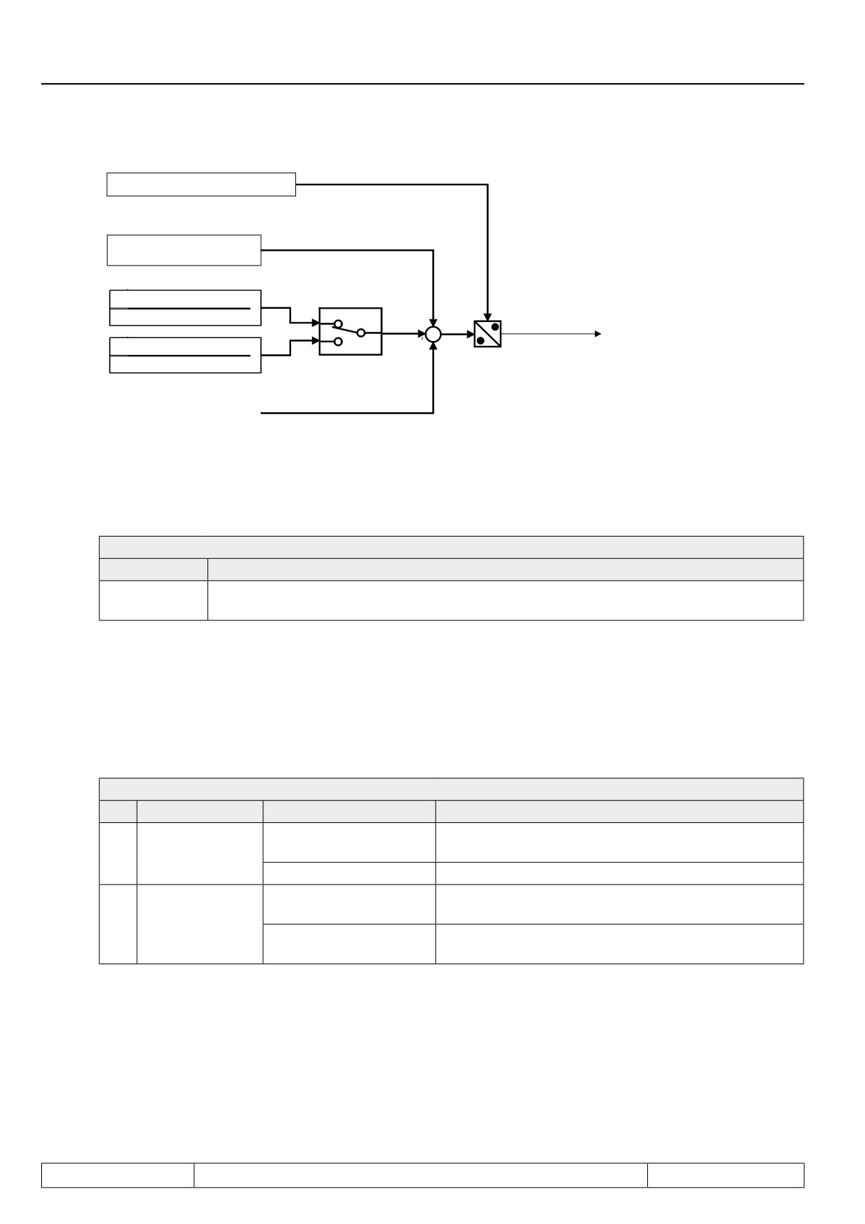
Quick stop dec. time (Pn.60)
Quick stop level (Pn.59)
Quick stop mode (Pn.58)
Apparent current ru.15)
Bit 0
Rated inverter current (In.01)
0
+
Actual ramp time
Active current (ru.17)
+
1
Rated inverter current (In.01)
1
Time monitoring abnormal stopping
For safety, a maximum time for the abnormal stopping-function can be programmed.
Pn.68: Max. abn. stopping time
Value
Explanation
time after which the inverter switches from malfunction- ("abnormal stop" A.XX) to the error
0,01...100,00 s
state (E.XX)
If the inverter is still in the malfunction state (A.XX) after this time (no RESET or automatic restart was execut-
ed), the inverter switches off the modulation and changes to the corresponding error state (A.XX => E.XX).
Abnormal stopping via control word
Abnormal stopping can also be triggered via the control word (SY.43 and SY.50, respectively ). The parameter
Pn.58 abnormal stopping mode determines the behaviour of the abnormal stopping via control word.
Pn.58: Quick stop mode
Bit
Meaning
Value
Explanation
Abnormal stop-
Shutoff of the modulation after reaching of speed 0 due
0:Sy.50 modulation off
2
ping via control
to abnormal stopping
word (Sy.50)
4: Sy.50 modulation on
Fast stop with holding torque on reaching speed 0
The status bit "abnormal stopping" remains active until
0: Status bit on
Status bit
at
leaving the function
3
standstill
The status bit "abnormal stopping" is reset when the
8: Status bit off
drive has reached standstill
Page7.13 - 14
Protective Functions
7.13.3Automatic restart
With the automatic restart, the inverter error automatically resets or automatically terminates the abnormal
stopping caused by a malfunction or pre-warning.
The function can be activated separately for the various errors and malfunctions with the Pn-parameters.
The automatic restart only makes sense if the error can be expected based on the application. Normally, the
cause of the error must first be investigated and eliminated before the drive can be put back in operation by
executing the reset.
Therefore, it must be selected after which errors an automatic restart should be executed
Because of the independent starting of the machine safety measures must
Attention:
be provided for operating personnel and machine!
7.13.3.1
Undervoltage error (E.UP)
In Pn.00 "auto retry UP", the automatic restart for the undervoltage error is activated in the factory setting.
A typical application for the automatic restart UP (Pn.00) is operation on a bad power grid where sporadic
brownouts are to be expected. With this function, the application continues running as soon as the mains vol-
tage is sufficiently high again.
For the undervoltage error, a time can be defined within which the automatic restart is permissible.
Pn.76: Max. E.UP warning time
Value
Explanation
If the function automatic restart is activated, it is always executed after the undervoltage error
7
0: off
(independent of the length of time the error was present). The error bit in the status word
SY.44 and SY.51, respectively, is set as long as the inverter is in state E.UP.
After expiration of this time, no automatic restart is executed anymore. During this time, the
0,01...32,00 s
error bit in status word SY.44 and SY.51, respectively, is not set. The progress message in
ru.00 and the switching condition "4: error", however, display the undervoltage error.
7.13.3.2
Overvoltage error (E.OP)
The error overvoltage occurs mostly at high speed. By activation of Pn.01 "auto retry OP", it can be avoided
that the drive "spins down" for a long time after this error. This function makes sense only in combination with
the speed search (see chapter 7.15).
The base-block time (bbL) is at least 1 second, even if the value in uF.12 "base-block time" is smaller. Further-
more, the base-block time before the restart is always observed, even if uF.13 "base block voltage level" is
undershot.
7.13.3.3
Overcurrent error (E.OC)
The automatic restart after occurence of an overcurrent error is activated with Pn.02 "auto retry OC". It can be
used if burst-like overloads of the FI, e.g., due to blocking of the motor, can be expected in v/f-characteristic
operation.
The base-block time is treated as in overvoltage errors.
After 10 restart attempts, the inverter state must be unequal to the base-block time or the overcurrent error for
at least one second, otherwise the restart is aborted.
Page7.13 - 15
Protective Functions
7.13.3.4
Malfunction messages and pre-warnings
In the parameters Pn.03, Pn.05, Pn.07, Pn.08, Pn.10, Pn.12, Pn.14, Pn.16, Pn.18, Pn.66, Pn.75 and Pn.81,
with the values 3...5, a malfunction response with automatic restart is selected.
The base-block time is observed only if the drive is above uF.13 "base block voltage level".
7.13.4Base block
After shutdown of the modulation (e.g., when opening the control release or if an error occurs), one must wait
for the time shown in uF.12 "base-block time" before the modulation can be switched on again. During this pha-
se, ru.00 shows the status "motor de-excitation" and the display shows "bbL", respectively.
If ru.42 "modulation grade" is below uF.13 "base block voltage level" when switching off the modulation, there
is no base-block time. Even at low frequencies, the base-block time is not observed.
Exception: After overvoltage- or overcurrent-error, a minimum base-block time of 1s is inserted.
The parameters uF.12 and uF.13 are dependent on the power circuit and serve only as information for the user
on which minimum switch-off times to expect in the application.
In parameter Pn.65 / bit 8 "256: bbL is not displayed", the status message "motor de-excitation" can be sup-
pressed so that the event caused by the modulation switch-off becomes visible immediately.
PTC
A temperature sensor integrated into the motor winding is connected to the terminals T1/T2 of the inverter. If a
resistance of 1650...4000 Ohm is exceeded, motor overtemperature is detected. If the resistance drops below
750...1650 Ohm, the state motor overtemperature is reset.
Thermal contact (NC contact)
A thermal contact integrated into the motor winding is connected to the terminals T1/T2 of the inverter. The
opened state is recognised as motor overtemperature.
KTY
A special power circuit is necessary for this function. In Pn.62 "dOH warning level", a temperature in the range
of 0...200 °C is defined which, when exceeded, causes a motor overtemperature message.
The current temperature is indicated in ru.46 "motor temperature". With a standard power circuit Pn.62 has no
function. In the motor temperature display ru.46 only T1-T2 closed or T1-T2 open is displayed.
7.13.5Quick Stop
The abnormal stopping-function serves to shut down the drive (mostly in case of a malfunction) as quickly as
possible. Therefore, there is a separate ramp time (Pn.60: "Quick stop deceleration time") and, in closed-loop
operation separate torque limits (Pn.61: "Quick stop torque limit", Pn.67: "Quick stop maximum torque corner
speed"), which can be adjusted higher than the torque limits for normal operation, to provide the required fast
deceleration.
In V/F characteristic operation, one can choose in Pn.58 "Quick stop mode" between ramp generator and diffe-
rential controller. For the differential controller, the time constant is set in Pn.60. The setpoint of the differential
controller is defined in Pn.59: "Quick stop level", Pn.58 selects the actual value from either apparent current or
active current.
The abnormal stopping can be activated by malfunction as well as via the control word (Sy.50 Bit 8). The func-
tionality is the same in both cases but for state, "79: abnormal stopping" (StOP) is always displayed.
Page7.13 - 16
Protective Functions
For all modes, one can choose whether the abnormal stopping-bit is reset in the status word (Sy.51 bzw. Sy.44
Bit 8) on reaching standstill, or whether it remains active until leaving the function.
Pn.58: Quick stop mode
Bit
Meaning
Value
Explanation
The status bit "abnormal stopping" remains active until lea-
0: Status bit on
ving the function
3
Status bit at standstill
The status bit "abnormal stopping" is reset when the drive
8: Status bit off
has reached standstill
7.13.5.1
Quick stop in the V/F characteristic operation
For abnormal stopping with V/F characteristic control, the drive is decelerated with the adjusted ramp time, and
with the differential controller, respectively.
Pn.58: Quick stop mode
Bit
Meaning
Value
Explanation
0: Ramp generator
The deceleration time is Pn.60
Quick stop mode
The deceleration time is dependent on the difference
0
(V/F characteristic
1: Differential con-
current limit (Pn.59) - present current. The time con-
operation)
troller
stant of the controller is adjusted by Pn.60, the setpoint
is adjusted by Pn.59.
Current limit for deceleration refers to the apparent cur-
Quick stop act. value
0: Apparent current
rent
1
(V/F characteristic
Current limit for deceleration refers to the active cur-
7
operation)
2: Active current
rent
Depending on the setting of Pn.58, the ramp time of the abnormal stopping function or the time constant of the
controller are set in Pn.60.
Pn.60: Quick stop dec time
Value
Explanation
0..300 s
Ramp time and time constant of the controller, respectively
The current limit for the differential control is set in Pn.59 "quick stop level".
Pn.59: Quick stop level
Value
Explanation
0...200 %
Current limit for difference control = 0..200% rated inverter current (In.01)
Page7.13 - 17
Protective Functions
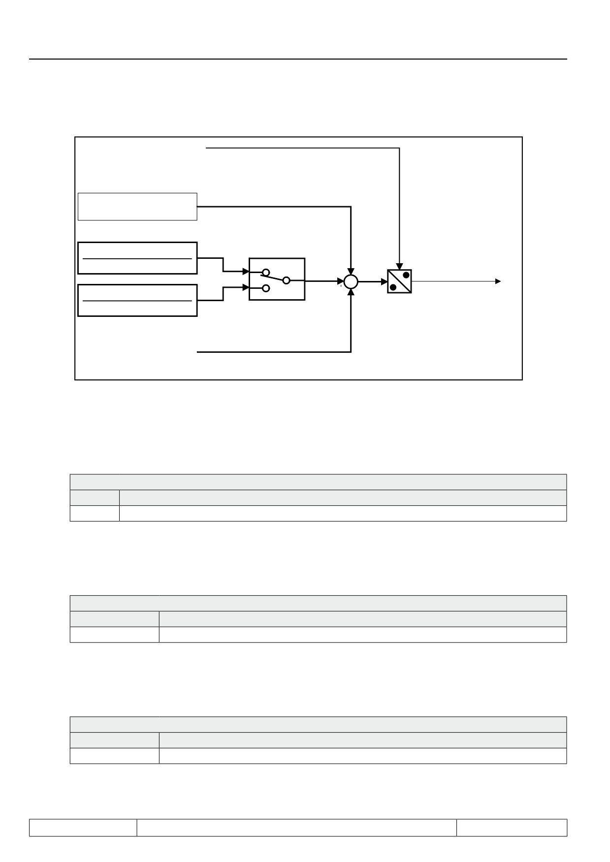
Block diagram of the differential control:
Quick stop dec time (Pn.60)
Quick stop level (Pn.59)
Quick stop mode (Pn.58)
Bit 0
Apparent current (ru.15)
Rated inverter current (In.01)
0
+
Actual ramp time
+
Active current (ru.17)
1
Rated inverter current (In.01)
1
7.13.5.2
Quick stop at closed-loop systems
For abnormal stopping with closed-loop systems, the drive is decelerated with the adjusted ramp time, and at
the torque limit, respectively.
Pn.60: Quick stop dec time
Value
Explanation
0...300 s
Deceleration ramp for abnormal stopping-function
For the abnormal stopping, the "normal" torque limitations of the application often do not apply since the auto-
matic shutdown is always a malfunction response. To permit a quicker deceleration with a greater torque here,
there is a unique torque limit for abnormal stopping.
Pn.61: Quick stop torque limit
Value
Explanation
0...32000.00Nm
Quick stop torque limit
The torque limitation superimposed by the limiting characteristic and the available current remain in effect.
For asynchronous motors, the maximum cutoff torque for abnormal stopping can also be increased to make
more torque available for braking, even in the field weakening range.
Pn.67: Quick stop maximum torque corner speed
Value
Explanation
0...32000.00Nm
the limiting characteristic for abnormal stopping is defined by dr.16 instead of Pn.67
Page7.13 - 18
Protective Functions
7.13.5.3
Time monitoring abnormal stopping
For safety, a maximum time for the abnormal stopping-function can be programmed.
Pn.68: Max. abn. stopping time
Value
Explanation
time after which the inverter switches from malfunction- ("abnormal stop" A.XX) to the error
0,01...100,00 s
state (E.XX)
If the inverter is still in the malfunction state (A.XX) after this time (no RESET or automatic restart was execut-
ed), the inverter switches off the modulation and changes to the corresponding error state (A.XX => E.XX).
7.13.5.4
Abnormal stopping via control word
Abnormal stopping can also be triggered via the control word (SY.43 and SY.50, respectively ). Then, the status
shows "79: Abnormal stopping" (StOP). In parameter Pn.58 "Quick stop mode", the behaviour for abnormal
stopping can be defined via control word .
Abnormal stopping mode determines the behaviour for abnormal stopping via control word.
Pn.58: Quick stop mode
Bit
Meaning
Value
Explanation
Abnormal stopping
0: Sy.50 modulation off
disabling of modulation after reaching speed 0
2
via control word
4:Sy.50 modulation on
Fast stop with holding torque on reaching speed 0
(Sy.50)
7
7.13.6Speed search
The speed search permits a relatively smooth engagement of the frequency inverter onto a running motor.
Without activation of the speed search, the motor is always slowed down first. In closed-loop operation with
encoder, this occurs at the torque limit, in closed-loop operation without encoder, the motor must be stopped
with DC-current braking.
On activation of the speed search, however, the current speed is determined and the drive is accelerated or
decelerated from this starting point to the setpoint speed, according to the adjusted ramps.
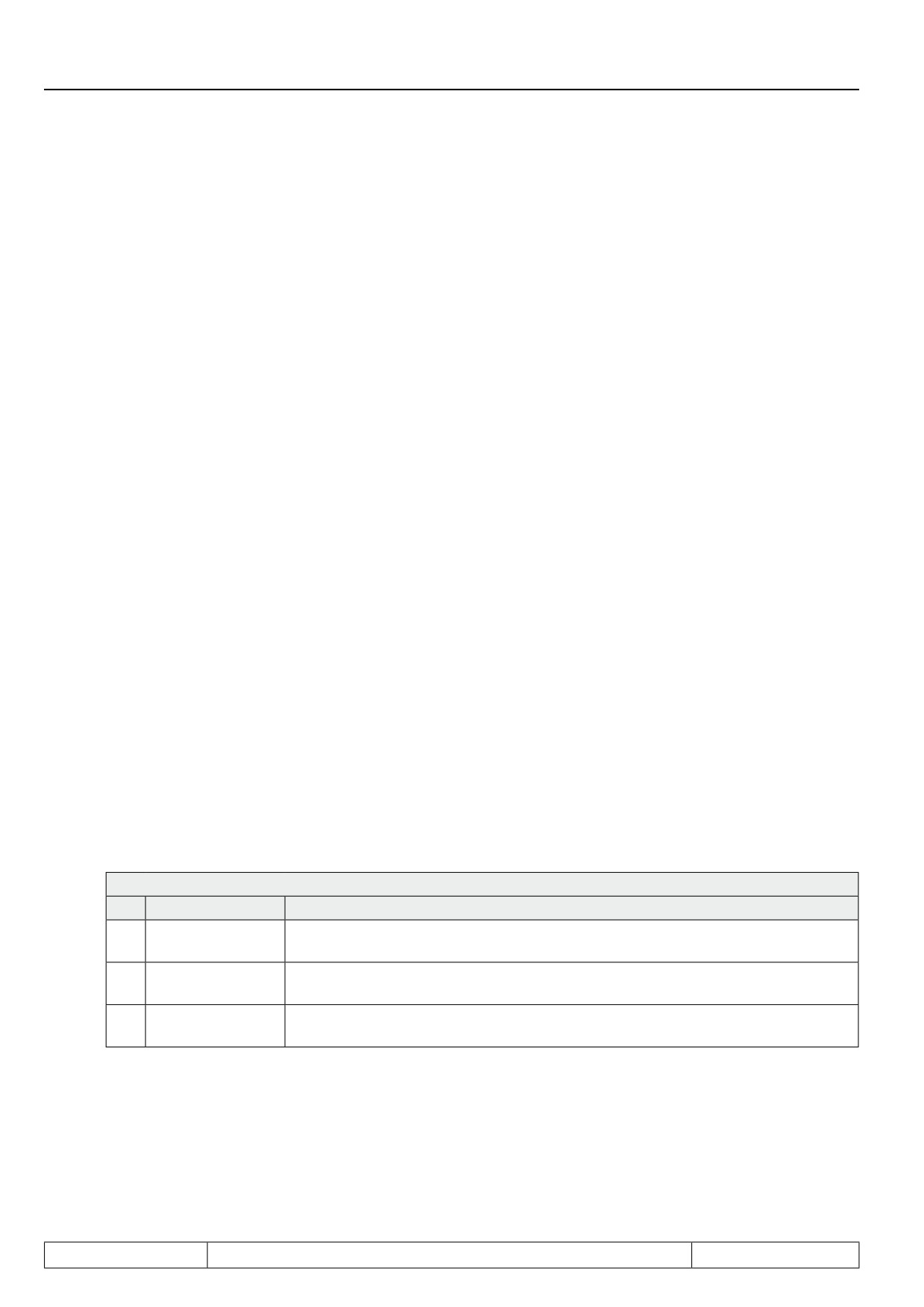
Parameter Pn.26 "Speed search condition" determines after which events the speed search is to be execut-
ed.
Pn.26 : Speed search condition
Bit
Meaning
Explanation
0
1: Speed search after noP
Speed search after the status "no control release"
1
2: Speed search after power-on-
Speed search after power on
reset
2
4: Speed search after reset
Speed search after execution of a reset
3
8: Speed search after auto reset
Speed search after automatic restart
4
16: Speed search after LS
Speed search after the status "standstill (modulation off)"
Page7.13 - 19
Protective Functions
7.13.6.1
Speed search in the open loop operation
The speed search mode determines the frequency and voltage jumps as well as the maximum load factor with
which the function works. Higher values let the function work faster, lower values make the function "softer".
7.13.6.2
Speed search at asynchronous motors in the closed-loop operation with encoder
In closed-loop operation with activated speed search, the ramp output value is set to the current actual speed.
After the motor flux has been built up, the drive runs up to the setpoint speed.
7.13.6.3
Speed search at asynchronous motor in the closed-loop operation without encoder
(ASCL)
In closed-loop operation without encoder, the current actual speed must be estimated from the motor model.
For special motors (e.g., high frequency spindles) or applications (e.g., operation in very high field weakening
range), this estimate for the engagement onto a running motor may not work. The speed is then calculated
incorrectly and the drive vibrates or the inverter raises a malfunction.
In these cases, the motor must be stopped by DC braking (see chapter 7.15.) before the drive can be restarted.
Generally, however, the speed search is the most jerk-free and quickest path to switch to a running motor.
7.13.7LAD-stop
The ramp stop function essentially fulfils two tasks. It reduces the risk of:
-
Overcurrent errors (E.OC) during the acceleration or deceleration phase (only for v/f-characteristic
operation)
-
Overvoltage error (E.OP) during the deceleration phase (in all operating modes)
By stopping the ramp if Pn.24 "LAD load level" or Pn.25 "LD voltage" is exceeded.
Moreover, the ramp stop function can be activated by a digital input.
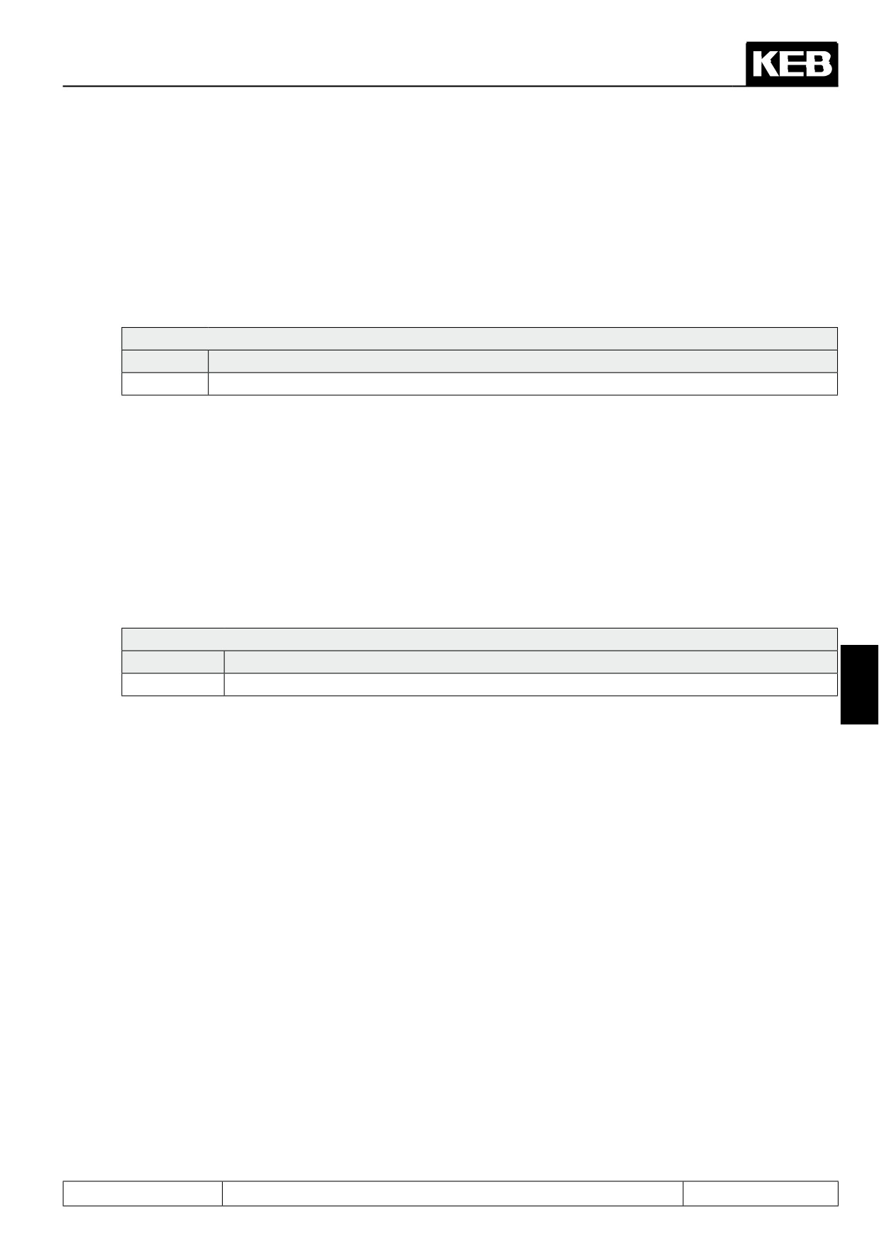
Pn.22 selects which of the ramps (acceleration, deceleration or both ramps) can be stopped.
Pn.22: LAD stop function
Bit
Meaning
Explanation
The acceleration ramp is stopped if Pn.24 "LAD load level" is exceeded or if the
0
1: LA stop
input programmed in Pn.23 "LAD stop input selection" is set
2:
Deceleration
The acceleration ramp is stopped if Pn.25 "LD voltage" is exceeded or if the input
1
stop U-abh.
programmed in Pn.23 "LAD stop input selection" is set
4: V deceleration
The deceleration ramp is stopped if Pn.24 "LAD load level" is exceeded or if the
2
stop I-abh.
input programmed in Pn.23 "LAD stop input selection" is set
In the operating modes positioning or synchronous running, this function is not active. If an abnormal stopping
ramp time is entered in Pn.60 for the abnormal stop, the deceleration stop is active.
Page7.13 - 20
Protective Functions
7.13.7.1
Current-dependent ramp stop
In V/F characteristic operation, overcurrent errors can occur due to short ramps.
Therefore, a current limit can be programmed with Pn.24 "ramp stop current level" that is frozen on exceeding
the ramp generator output value (ru.02).
In closed-loop operation, the current is limited in software via the control-internal current and torque limits.
The functions acceleration stop (LA-Stop) and current-dependent deceleration stop (LD-Stop (I)) are therefore
superfluous.
Pn.25: LD voltage
Value
Explanation
0 .. 200%
Current level at which the ramp is stopped
If the acceleration stop is active in the vector controlled operation, so that the interruption of the ramp via a
digital input can be used, the current level in Pn.25 must be set to 200% to avoid negative effects.
7.13.7.2
DC link voltage-dependent ramp stop
The LD-Stop (U) function can be used to prevent overvoltage errors during deceleration.
During deceleration energy is refeed into the frequency inverter, which causes a rise of the DC-link voltage.
If too much energy is recovered, the inverter can switch to overvoltage- (OP) error.
If the LD-Stop (U) function is activated with Pn.22, the DEC-ramp is stopped when the current DC link voltage
(ru.18) exceeds the adjusted LD voltage (Pn.25).
Pn.25: LD voltage
Value
Explanation
200V...1200V
DC-link voltage level at which the ramp is stopped
7
Overvoltage errors cannot always be securely prevented with this protection function, because after setting
the ramps and the speed controller, further deceleration can occur despite stopping the ramp. If the drive
decelerates, e.g., at the torque limit, and can therefore not follow the ramp, it does not help to stop this ramp.
An undershoot of the speed controller due to a sudden termination of the ramp can also lead to further energy
recovery in the DC link.
Generally, the deceleration process is slowed down by this protection function. For a dynamic deceleration, the
use of a braking resistor is necessary.
7.13.7.3
Ramp stop dependent on a digital input
With Pn.23 "LAD stop input selection", a digital input can be selected for triggering the ramp stop. This input is
only active if the stop is permitted in Pn.22 for the corresponding ramp.
Page7.13 - 21
Protective Functions
7.13.8Current limit constant run (stall function)
The Stall-function protects the frequency inverter against overload.
If the current (depending on the setting of the active or the apparent current in Pn.19 ) reaches the current limit
(Pn.20), an attempt is made to lower the load by increasing / decreasing the output frequency.
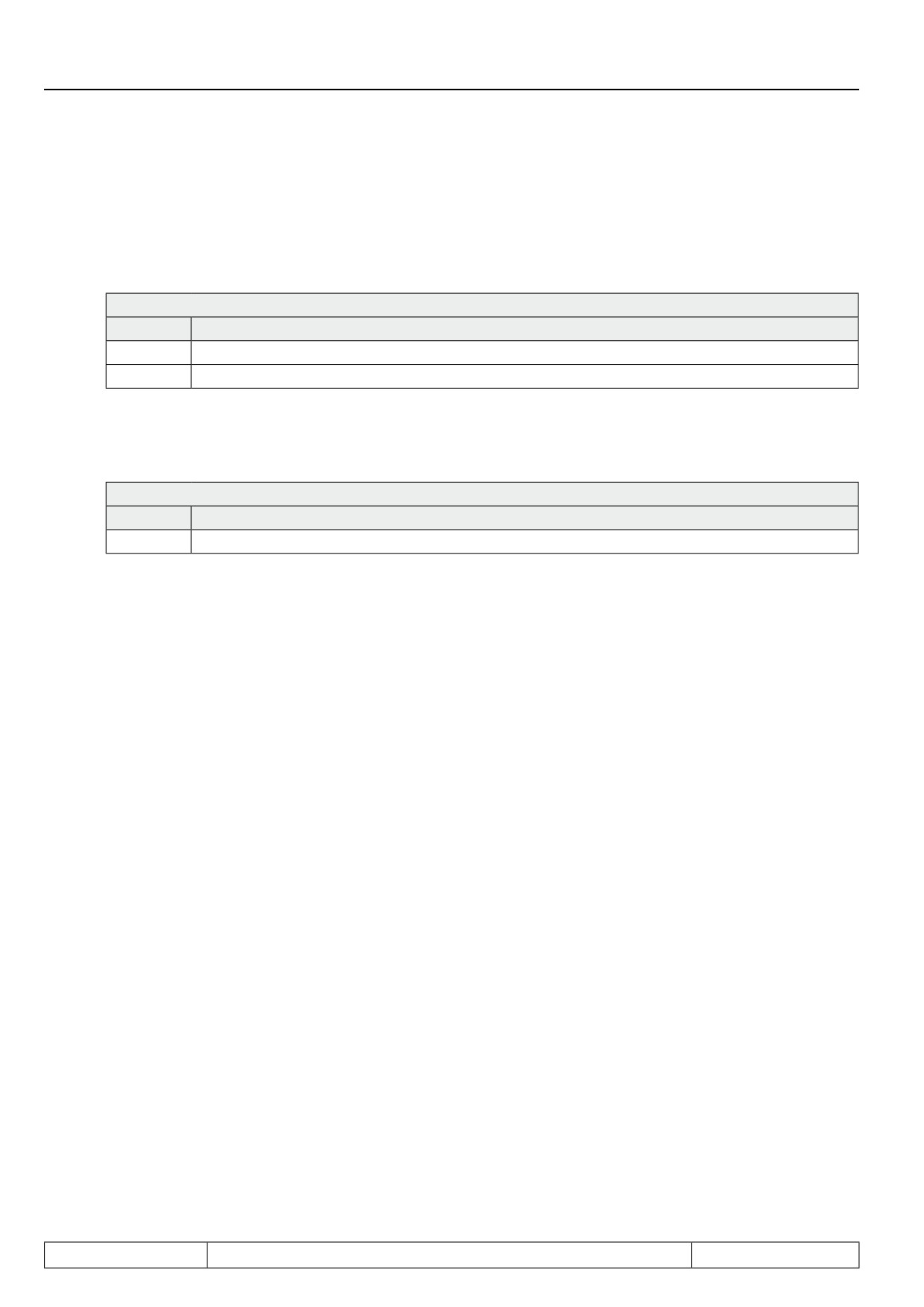
Pn.20: Stall level
Value
Explanation
0...199 %
Current limit in % (reference value: 100% = rated current of the FI (In.01))
200: off
Stall function deactivated
The rate of change of the output frequency is dependent on Pn.21. Depending on the setting of Pn.19, the ramp
time of the stall function or the time constant of the controller is adjusted here.
Pn.21: Stall acc/dec time
Value
Explanation
0...300s
Ramp time and time constant of the controller, respectively
Whether the output frequency must be increased or decreased depends on the torque characteristic of the
application. For a fan, e.g., the load factor increases with the speed, and the output frequency must be reduced
during overload. For a drilling machine, the load factor decreases with the speed, and the drive must therefore
be accelerated during overload.
When falling below the maximal constant current the inverter accelerates/decelerates again with the normal
ramp time. The stall function is active until the original setpoint speed is reached.
This protection function is active only for F5A-M in open loop operation (cS.00 = off).
Page7.13 - 22
Protective Functions
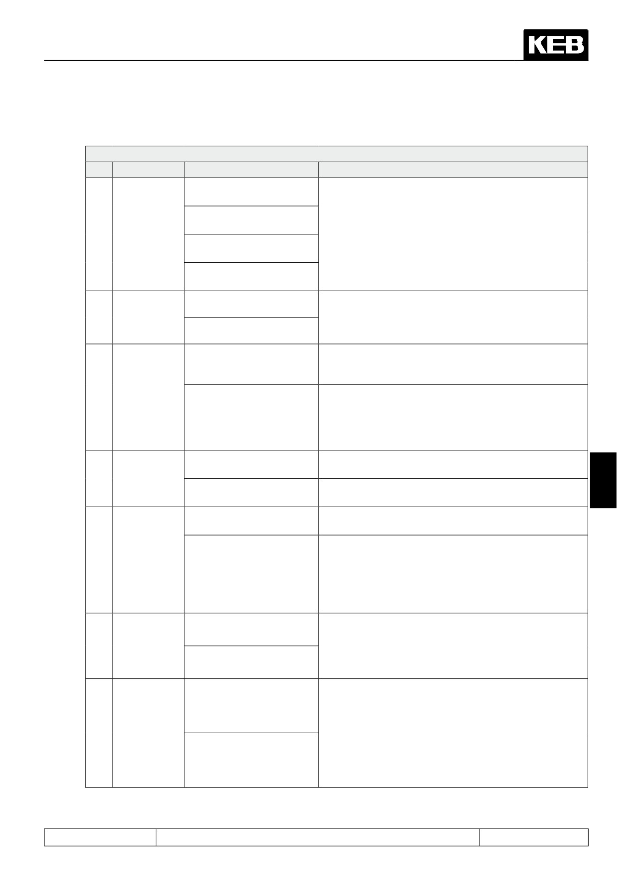
The basic mode of operation is determined with Pn.19:
Pn.19: Stall mode
Bit
Meaning
Value
Explanation
0: oP.06, 07 respectively
oP.10, 11
1: 0 rpm respectively
Final value to which it is possible to decelerate/accele-
Frequency
oP.10, 11
rate. Both limits (min. and max. setpoint, respectively)
0, 1
limiting
2:oP.06, 07 respectively
are always set, because the control direction can invert in
oP.40, 41
generator operation.
3: 0 rpm respectively
oP.40, 41
Control
With this bit, it is set whether the control direction (fre-
0: no change
characteristic
quency increase and decrease, respectively.) inverts in
2
in generator
generator operation. Only active if in active current control
4: Inversion
operation
mode.
The frequency is increased/decreased by way of the ramp
0: Ramp generator
generator. The ramp time is preset by Pn.21.
The increase / decrease of the frequency is done by a
3
Ramp control
controller. The rate of change is dependent on the dif-
8: Differential controller
ference current limit (Pn.20) - present current. The time
constant of the controller is adjusted by Pn.21, the set-
point is adjusted by Pn.20.
Stall function only active at constant run (see inverter
0: only at constant run
Release of
state)
4
7
the function
16: always (also during the
Stall function always active
ramp)
The stall function intervenes if the apparent current (ru.15)
0: Apparent current
exceeds the current level Pn.20.
The stall function intervenes if the amount of the active
current (ru.17) exceeds the current level Pn.20. Since
5
Variable
a distinction between motor and generator operation is
32: Active current
made only in the active current, the active current must
be chosen as the variable for the inversion of the control
characteristic in generator operation.
Fits the function to the torque / speed characteristic of the
0: Deceleration
application.
Control direc-
6
Examples: For a fan, one must decelerate if the current
tion
level is exceeded. For drilling machines, one must acce-
64: Acceleration
lerate.
Determines whether the current limit that activates the
stall function should be decreased above the rated point.
0: no
The decrease is then done according to the following
Level decre-
formula:
ase above
7
rated fre-
²
quency
Current limit = Pn.20
(————)
128: yes
Actual frequency (ru.3)
Page7.13 - 23