KEB COMBIVERT F5-A,-E,-H 4.0. APPLICATION MANUAL (2008) - page 18
Positioning and Synchronous Control
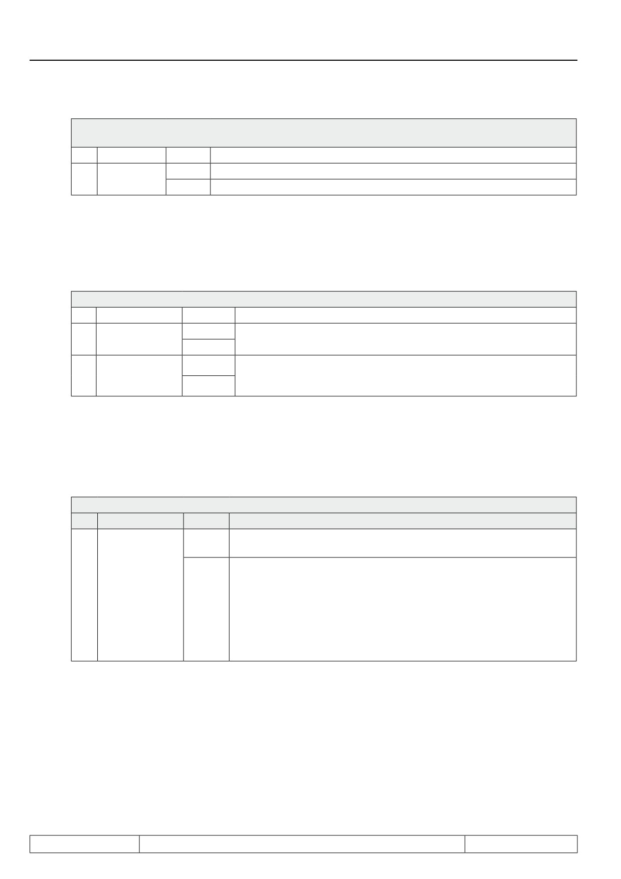
Sy.43: Control word long
Sy.50: Control word low
Bit
Meaning
Value
Explanation
Start Positio-
0
Without function for positioning
10
ning
1024
Switch from not activated to activated starts positioning
Starting a new positioning is only possible if bit 10 has temporarily been set to 0.
● by writing a new target position to parameter PS.24 or by set changeover
To start a positioning by writing a new target position or by set changeover, the following adjustments
must be made in PS.00:
PS.00: Posi / synchronous mode
Bit
Meaning
Value
Explanation
Start positioning
0: off
For "start positioning by set change = on", every set change automatical-
9
via set change
512: on
ly generates a "start positioning" command.
0: off
For "start positioning PS.24 = on", a "start positioning" command is ge-
Start positioning
12
nerated each time parameter PS.24 is written to (independent of the in-
PS.24
4096: on
dex).
To perform a positioning, the inputs wired as limit switches (inputs with functions "forward" and "backward")
must be active. If the hardware limit switches are not to be used, the protection functions in Pn.07 "Proh. rota-
tion stopping mode" must be deactivated (value 6: function switched off).
If the target position can still be changed during a running positioning is determined by PS.00 bit 3
PS.00: Posi / synchronous mode
Bit
Meaning
Value
Explanation
After starting a positioning, the target position that was valid at the time of
0: off
the "start positioning" command is approached.
For a new "start positioning" command during the acceleration or constant
running phase of a running positioning (status "122: positioning active"),
Termination due
the new target is adopted and approached if it is accessible with the de-
3
to new start po-
fined acceleration / deceleration /jolt times. (For the processing of inac-
sitioning
8: on
cessible positions, see chapter 7.12.4.15) For a sequential positioning, the
running positioning sequence is aborted. With the new "start positioning"
command, a new positioning sequence is started with the index program-
med in PS.28 "start index new profile".
If the drive leaves the vector controlled operation (first "start positioning" after activation of the positioning
mode), or if during an active positioning a new "start positioning" command is given, the new target is possibly
inaccessible with the adjusted ramp and jolt times.
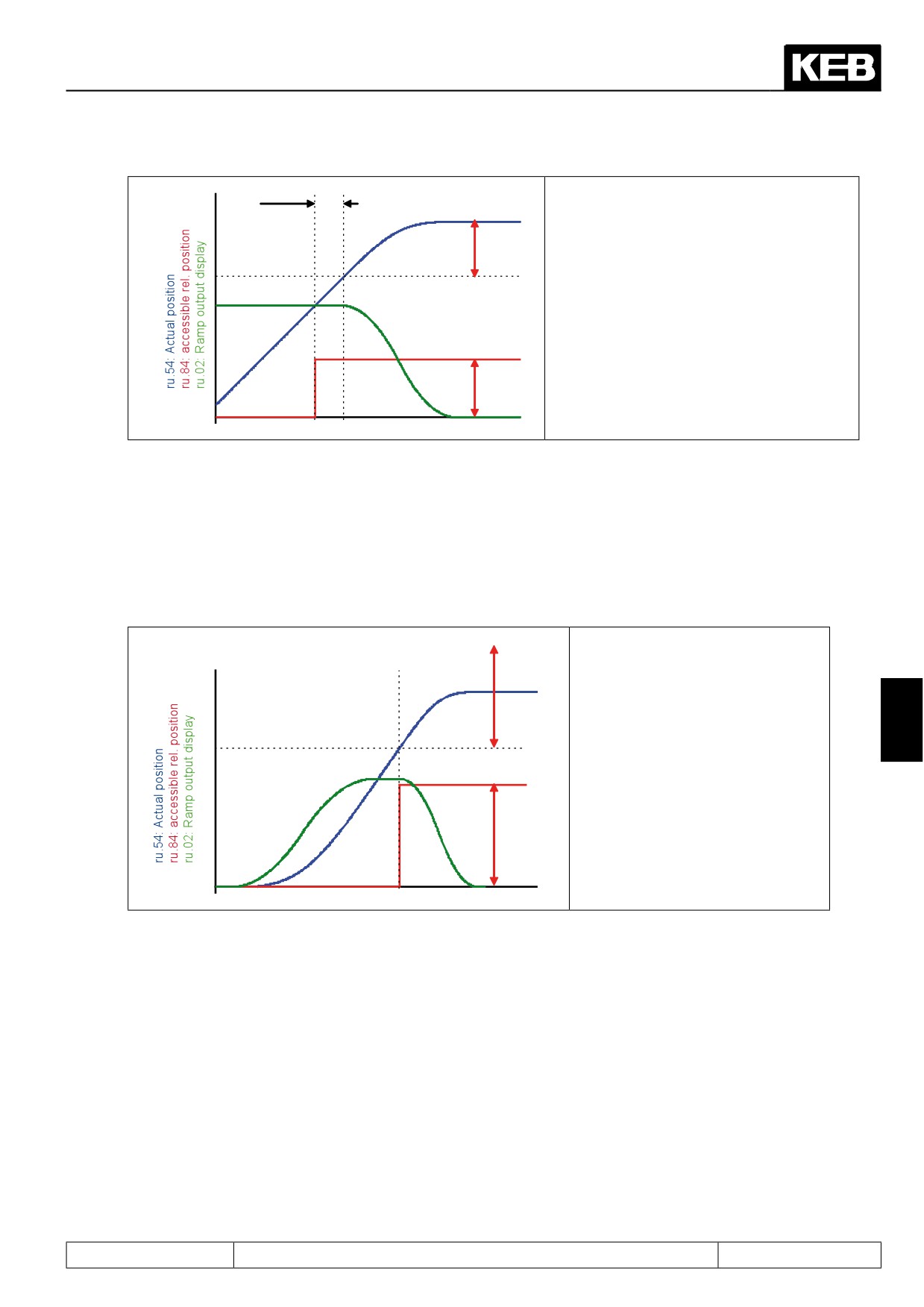
Parameter ru.84 "accessible relative position" shows the distance that the target must have to the actual posi-
tion ru.54 at the time of the "start positioning" pulse to be accessible with the programmed ramp and S-curve
times.
Page7.12 - 64
Positioning and Synchronous Control
Example:
Start of the deceleration
Start
to target approach
At the "start positioning command", ru.84
positioning
indicates that the target must be at least
ru.84
200000 increments away from the current
actual position to be accessible with the pro-
grammed ramps.
The target is further away and the drive po-
sitions to the target.
The deceleration phase starts when the
amount of ru.84 ahead of the target is re-
ru.84
ached.
If the target is inaccessible with the ramps from the oP-parameters, the ramp times can be changes online in
the event of a new "start positioning" pulse. For that purpose, there is the parameter PS.32 "limit acc/dec red-
ucing %".
Note: For the case of a start from the vector controlled operation, the online adaption is not active. In parameter
PS.32, a factor between 25 and 100% can be set. 25% means that the ramp and S-curve times may be reduced
to maximally 25% and increased by up to a factor of 4. The value 33% in PS.32 would correspondingly allow a
change of between 33% and a factor of 3 of the values set in the OP-parameters.
ru.54 "Actual position" + ru.84 "ac-
New „Start positioning“
cessible rel. position" is greater than
the target.
I.e., the target would be inaccessible
without ramp decrease.
7
In this example, the same values are
set for the
deceleration ramps as for the acce-
leration ramp.
With PS.32, the ramp times are shor-
tened so that the target is reached in
ru.84
a shorter distance than ru.84
The new "start positioning" command must occur within the positioning, in the acceleration or constant running
phase. In the deceleration phase to the final target approach, the new starting pulse leads to the status "position
inaccessible".
If the new starting pulse is received in the correct phase, but the target is inaccessible despite ramp adjustment
, the drive enters the state "position inaccessible" with the default ramp/jolt times.
The parameter PS.32 is similar to the parameter PS.44 "limit acc/dec corr. %" in its mode of action. PS.44,
however, works only for ramp changes necessitated by flying referencing with adjustment. PS.32, on the other
hand, is responsible for adjustments based on new target settings.
Furthermore, the ramp can also be changed during the acceleration phase by PS.32 if the new target setting
makes it necessary.
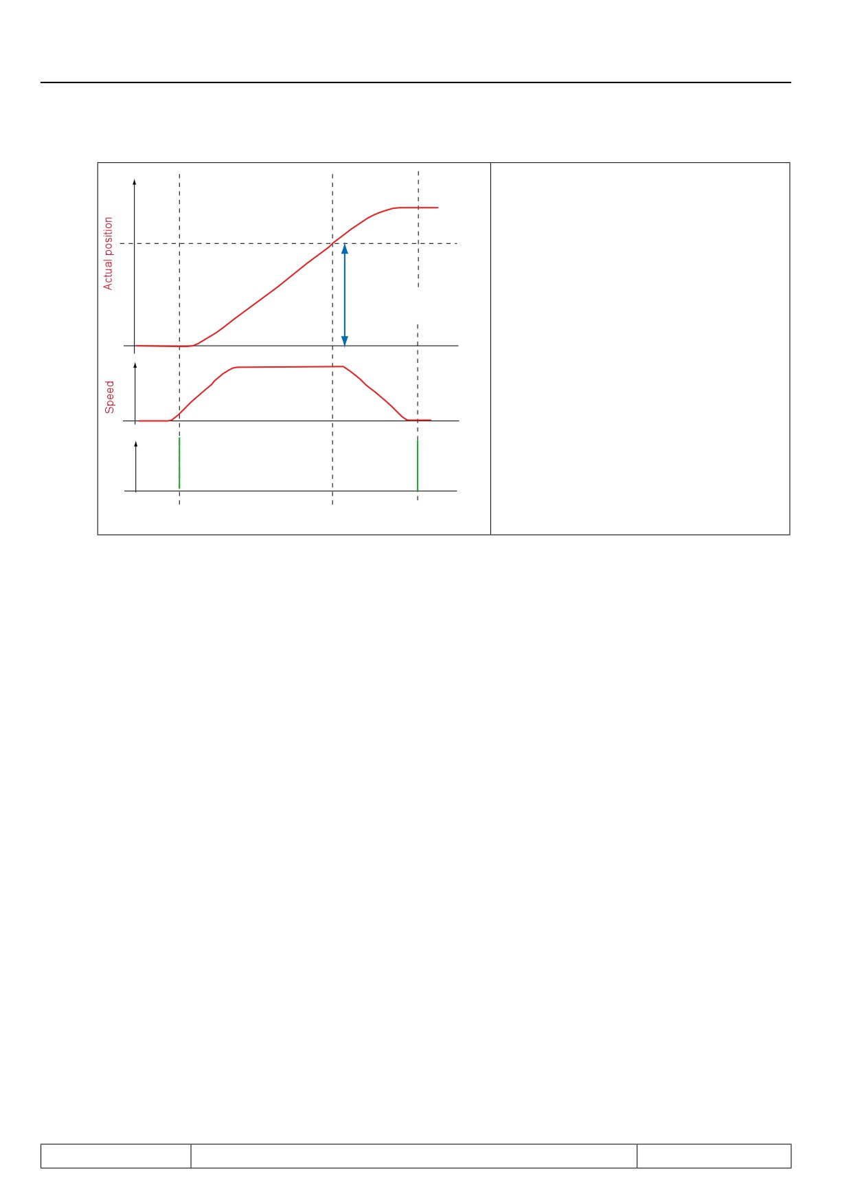
With the parameter PS.53 "distance for no abort", unwanted "start positioning" commands can be masked.
Since the last "start positioning" command, the drive must have travelled a greater distance than PS.53 so that
a new starting command is accepted during a running positioning.
Page7.12 - 65
Positioning and Synchronous Control
Example:
At the "start positioning command", ru.84 indi-
cates that the target must be at least 200000
increments away from the current actual po-
sition to be accessible with the programmed
ramps.
The target is further away and the drive posi-
PS.53: Distance
for no abort
tions to the target.
The deceleration phase starts when the
amount of ru.84 ahead of the target is rea-
ched.
New „Start Positioning“
commands are not accepted
in this range
First „Start positioning“
Target reached
Page7.12 - 66
Positioning and Synchronous Control
7.12.4.15
Posi mode / not reachable positions
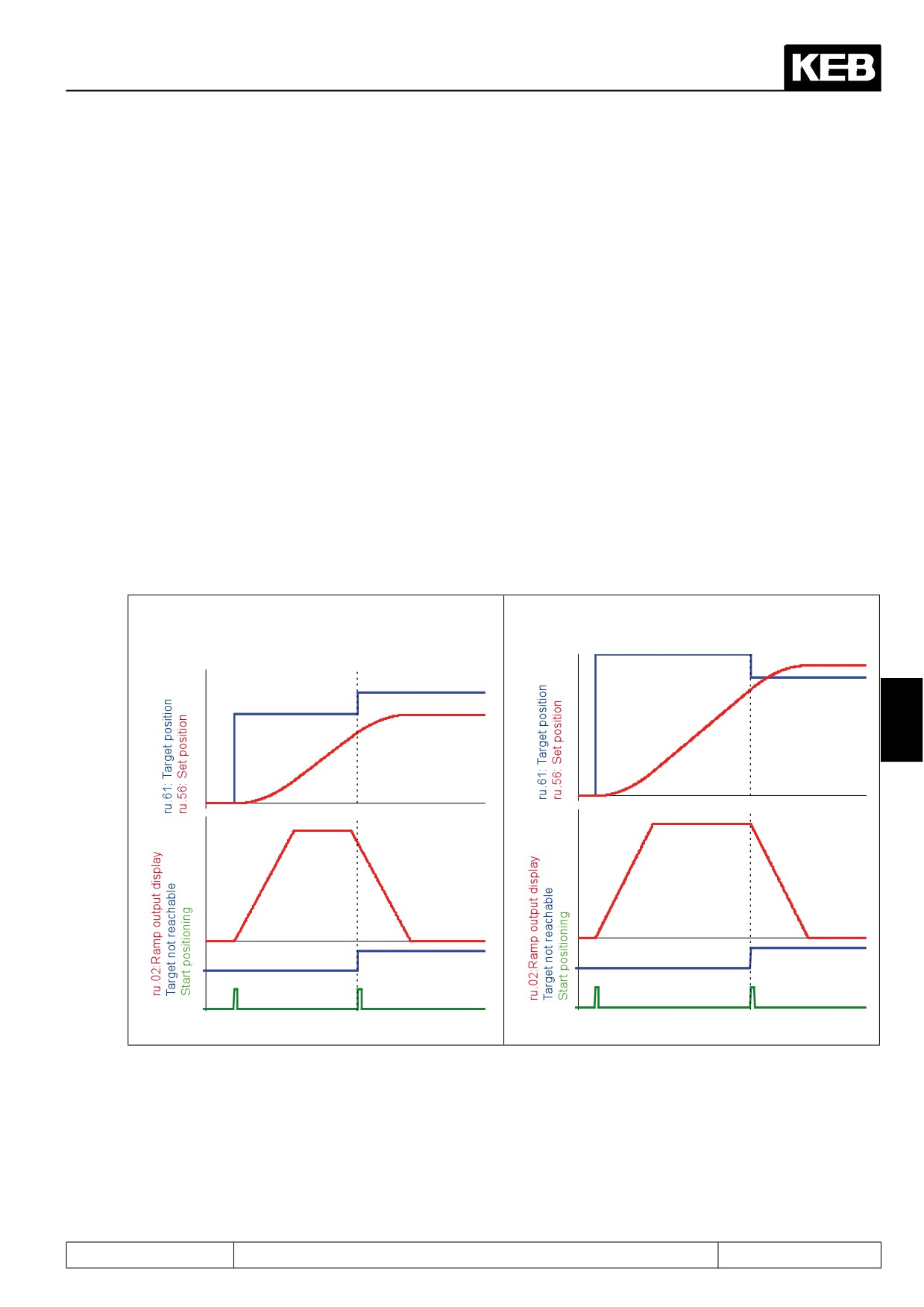
An "inaccessible position" is a target position that cannot be reached with the programmed acceleration / de-
celeration and jolt times.
This can occur in the following circumstances:
● Transition from vector controlled to position controlled operation due to the first "start positioning" after
activation of the positioning mode
● Change of the target position during a running positioning by a new "start positioning" signal
● during sequential positioning, when no stop is scheduled at the target
● due to a change in the actual and set point positions by flying referencing with adjustment
● if the drive is running at the time of the "start positioning" command and a rotation change is required for
the positioning
I.e., every time the drive is running at the time of the "start positioning" command, inaccessible positions can
occur.
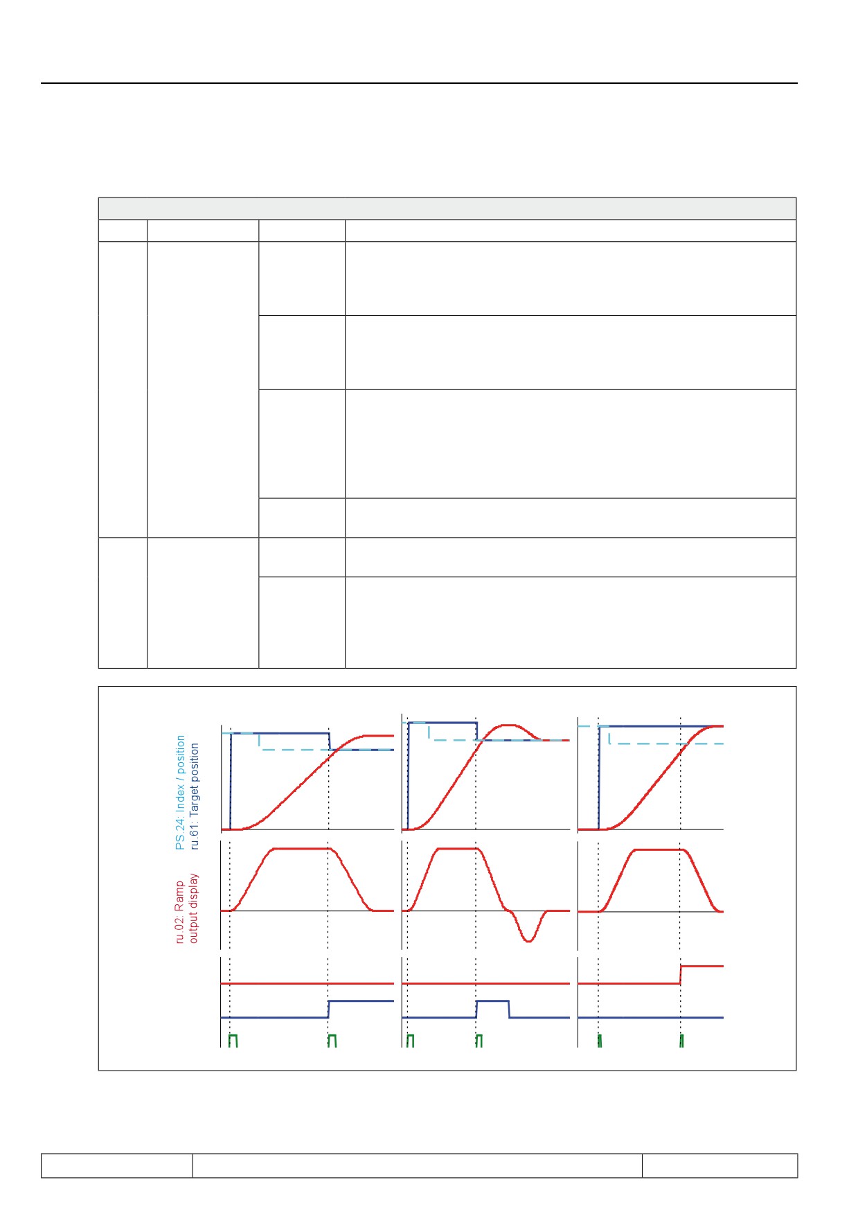
Also, if a new "start positioning" pulse is given during the deceleration phase to the original target, and the S-
curves are switched off, the message "inaccessible position" is generated because an adjustment during the
final approach to target is only executed during the lower S-curve.
Position not reachable, because new
Position not reachable, because new target is nearby
„Start positioning“ during deceleration
ramp
7
Page7.12 - 67
Positioning and Synchronous Control
The response to this status is selectable via PS.00:
PS.00: Posi / synchronous mode
Bit
Meaning
Value
Explanation
The drive stops with the adjusted ramps. Status ru.00 shows "123:
position inaccessible". This status is reset only by deactivation of the
0: stop
positioning module. While this status is active, no new "start positio-
ning" commands are accepted.
The drive stops with the adjusted ramps In status ru.00, "123: position
64: stop
inaccessible" is shown during the deceleration ramp. After reaching
+ new
standstill, a new positioning to the target position starts automatically
attempt
If position not
(status changes to "122: positioning active").
6 / 7
reachable
This function is required only for sequential positioning: The target
positions of the individual positioning steps are traversed, even if the
128: new
target speed set in PS.25 cannot be reached. This permits checking
attempt
where the positioning sequence has to be changed or adjusted so that
target position and target speed can be reached. This should facilitate
the parametrisation of the index speeds / positions.
192: reser-
reserved
ved
The behaviour of the drive is determined by PS.00 bit 6 / 7 (explana-
0: off
tion see above)
If the new target is inaccessible, the "start positioning" command
Ignore position,
8
is ignored. With a digital output, the ignoring of the position can be
if not reachable
256: on
displayed. The positioning module remains active, new "start positio-
ning" commands are executed. The digital output can be reset only by
deactivation of the positioning module.
Stop
Stop + new test
Ignore not reachable target
Ignore new
target
Target not
reachable
Start posi-
tioning
Page7.12 - 68
Positioning and Synchronous Control
7.12.4.16
Posi mode / stop positioning
A deactivation of the input occupied with the function "positioning /synchronous activation" concludes the po-
sitioning mode. A running positioning that was aborted by the deactivation cannot be resumed after switching
the input back on.
If the input remains activated, an active positioning can be interrupted by quick stopping, deactivation of the
control release, triggering of the "power off" function or occurence of an error (e.g.,: E.OC, E.OP, etc.).
After the drive is "ready for positioning" again, an interrupted positioning must be restarted with a "start posi-
tioning" command.
With parameter PS.00, one can select how the drive should behave after an error occurs (i.e., after interruption
of an active positioning):
PS.00: Posi / synchronous mode
Bit
Meaning
Value
Explanation
0: Starting
The target position (PS.24) from the starting index block is approa-
index from
Behaviour after
ched with the first "start positioning" after the interruption.
5
PS.28
error
32: last tar-
The target position that was positioned to when the interruption
get position
occurred will be approached with the first "start positioning".
Note: a sequential positioning is aborted only if the error (the interruption) occurred during an active positioning.
If the drive is stopped at the target (even if it is only an intermediate target of the sequential positioning), swit-
ching off the control release, for example, does not lead to a termination of the sequential positioning.
An active positioning can also be interrupted by setting bit 11 in control word Sy.43 or Sy.50
(field 2048: "activate interruption").
In contrast to a termination due to abnormal stopping, the ramps from the OP-parameters are used and started
7
S-curves are not interrupted in a termination initiated by the control word. The modulation remains on.
If bit 11 "termination" has again been deactivated in the control word, there are two possibililties for the drive
to continue:
PS.52: Automatically execution positioning after STOP
Value
Explanation
The drive waits for a new "start positioning" command. The current position setpoint PS.24 is
0: off
inherited for the new positioning.
The drive automatically starts a new positioning on the target that was approached at the
1: on
time of the termination by the control word. A change of the position setpoint PS.24 while the
"termination"-bit is set is ignored.
Page7.12 - 69
Positioning and Synchronous Control
7.12.4.17
Analog position setting
By means of the analog parameter setting, the parameter PS.24 "index position" can also be adjusted. (For
more detailed information on the analog parameter setting, see chapter 7.15.9 and for the adaption of the ana-
log channels, see chapter 7.15).
To set a position setpoint in PS.24 "index position" by analog input, the following adjustments have to be
made:
● in PS.23, select the index that is to receive the position setpoint
● select PS.24 as the target for the analog parameter setting An.54: Analog parameter setting destination
= 1318h (bus address PS.24)
● In An.53, select which analog channel is to provide the position setpoint
● Parametrise the analog channel (filter, amplification, offset, etc.)
● Configure the conversion of the analog value in the parameter value for PS.24:
An.55: Analog parameter setting offset defines the parameter value at analog setting 0%
An.56: Analog parameter setting max. value defines the parameter value at analog setting 100%
Parameter value PS.24 = An.55 + (An.56 - An.55) x analog value
Example: an analog value of -100%..+100% shall permit setting position values of 100000 to 300000
increments. An.55 and An.56 must then be parametrised as follows: An.55 = 200000 An.56 = 300000
7.12.4.18
Analog position output
Via the analog outputs ANOUT, position values can also be issued. (For further information on adaption of the
analog outputs, see chapter 7.15).
For the analog setting of actual position (ru.54) or set position (ru.56), the following adjustments must be
made:
● for an analog output (ANOUT1 or 2), choose actual position (An.31 / An.36 = 27) or setpoint position
(An.31/ An.36 = 28) as the output value
● configure the conversion of the position value to an analog value:
Position for which 0% analog value is issued: PS.41 "Reference position 0%"
Position for which 100% analog value is issued: PS.42 "Reference position 100%"
Example: for position values in the range of 100,000 to 300,000 increments, an analog value of
-100% to 100% is to be issued. PS.41 and PS.42 must then be parametrised as follows: PS.41 = 200.000,
PS.42 = 300.000
● Parametrise analog output (amplification, offset)
Page7.12 - 70
Positioning and Synchronous Control
7.12.4.19
Target window
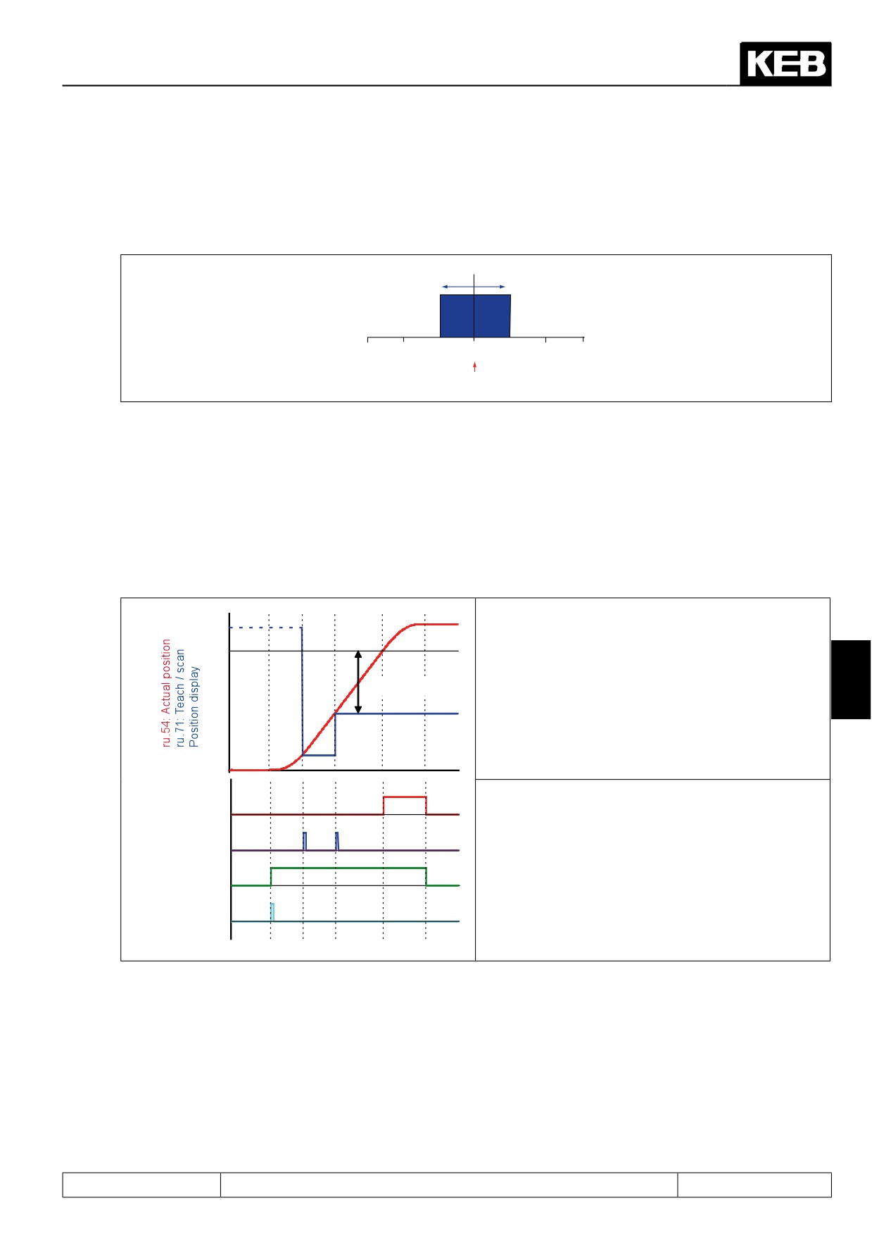
In parameter PS.30 "target window", the target window range is given. The target window has been reached if
the actual position is in the range of +/- PS.30 / 2 around the target position.
PS.30 Target window = 1000
4000
5000
6000
ru.61 Target position = 5000
7.12.4.20
Position scan
With parameter PS.37 "position scan index input selection", or via the digital Input function (di.24...di.35) "scan
position", an input can be defined for scanning the actual position (ru.54) with the positive edge.
The position scan happens only in status "positioning active". The scanned actual position value (ru.54) is dis-
played in parameter ru.71 "teach/ scan position". Each further edge overwrites the old scan position.
Dependent on the scanned position, a digital output can be set. The switching condition "75: amount current
position-scan position > level" must be chosen for this.
The output function "switching condition 0" is reset
by:
● Setting of a new target position
● Reaching of the target position
7
Switching level 0
● The target position is not reachable
● Quitting the positioning mode
Note:
Switching condi-
As long as the switching condition remains set, the
tions 0
teach-function
(see chapter
7.12.4.21) cannot be
Position scan
used.
Positioning active
Start positioning
Page7.12 - 71
Positioning and Synchronous Control
7.12.4.21
Teach function
With parameter PS.37 "teach index input selection", or via the digital Input function (di.24...di.35) "store position
(teach)", an input can be defined for scanning the actual position (ru.54) with the positive edge.
The scanned value is displayed in parameter ru.71 "teach / scan position" and stored in PS.24 as the target
position. Parameter PS.35 "teach mode" determines which positioning block (which index) the target position
is stored in.
PS.35: Teach mode
Value
Explanation
The current position is written to the positioning block pointed to by para-
0: Write index PS.23
meter PS.23 "index selection".
The current position is written to the positioning block pointed to by para-
1: Write index PS.23 incr.
meter PS.23 "index selection" and subsequently, PS.23 is increased by 1
(limited to maximum index 31).
The current position is written to the positioning block pointed to by para-
2: Write index PS.28
meter PS.28 "start index new profile". Since PS.28 is set-programmable,
positions can be linked with sets this way.
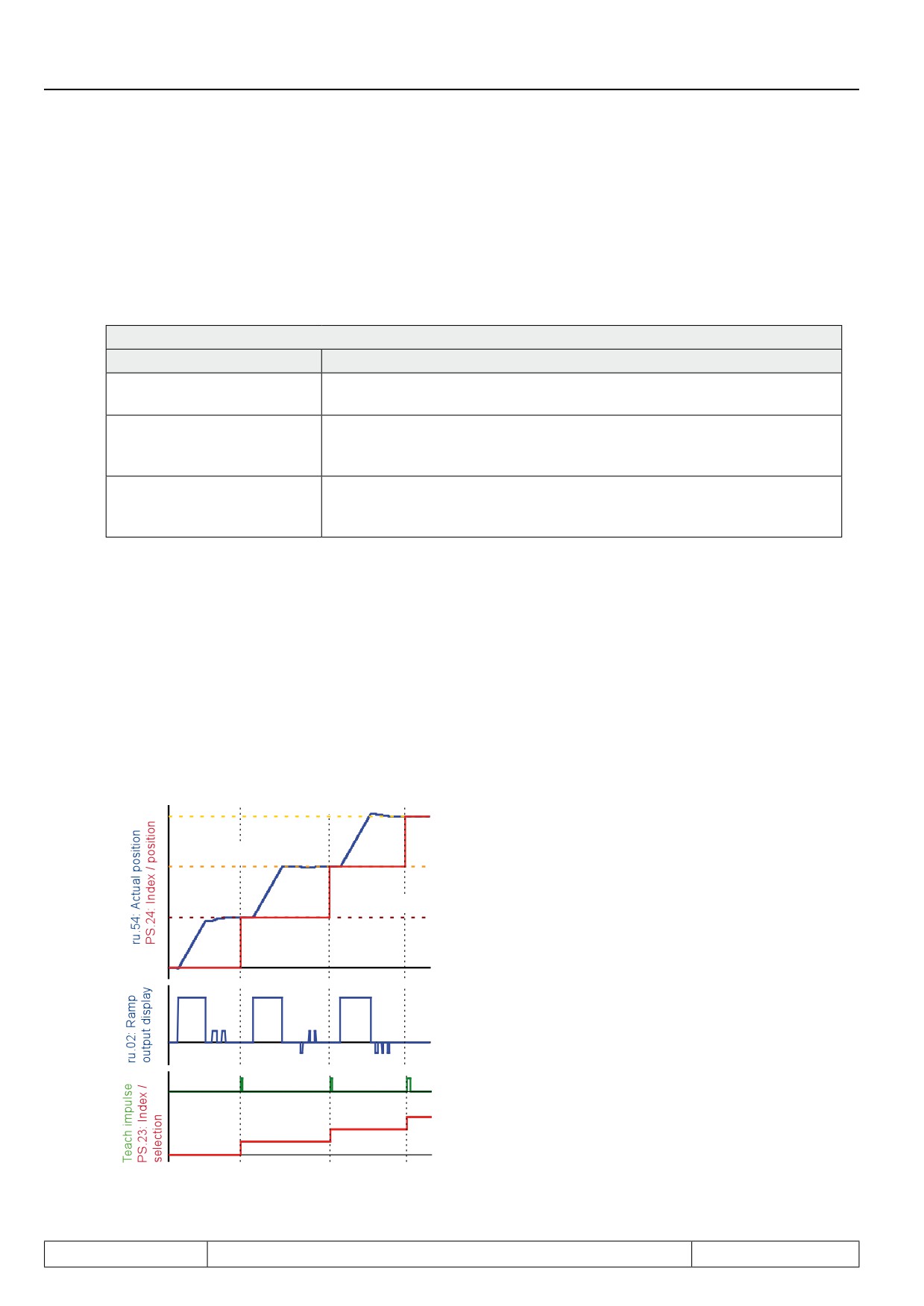
Example: Teaching of target position
An undercarriage shall "learn" the position values belonging to a storage location (the position value shall be
taught). In inching mode, the drive is brought to the position that is to be used later as the target of the positio-
ning (i.e., the storage location on a shelf). The drive is in vector controlled mode, i.e., the input activating the
positioning mode is not set.
Since several storage locations are to be taught consecutively, the setting is PS.35 "teach mode" = 1. If the
correct position is reached, it is registered as the target position by the teach-pulse. After that, the next storage
location is approached.
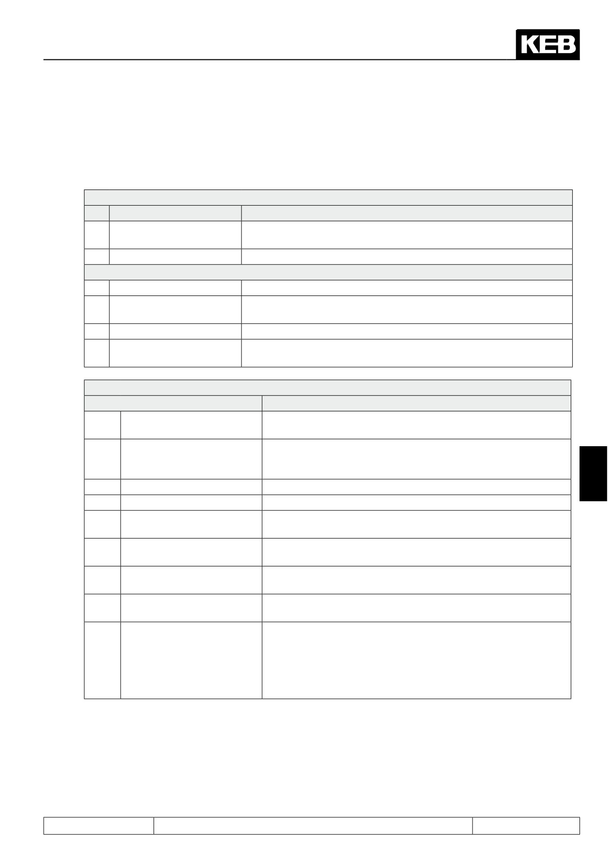
The following figure illustrates the example:
With the digital inputs, 3 constants are selected:
PS.24 Index 2
● higher speed for coarse target approach constant
PS.24 Index 1
1 = 300 rpm
● inching mode for exact target approach
PS.24 Index 0
Fixed value 2 = 50 rpm
Fixed value 3 = -50 rpm
The desired position is approached in vector controlled
operation.
With a teach-pulse (positive edge of the chosen digital in-
put), the current actual position is registered as the target
position of a positioning block.
The process starts with the index currently selected in
PS.23. Thereafter, the index is increased after every tar-
get position acquisition.
Page7.12 - 72
Positioning and Synchronous Control
7.12.4.22
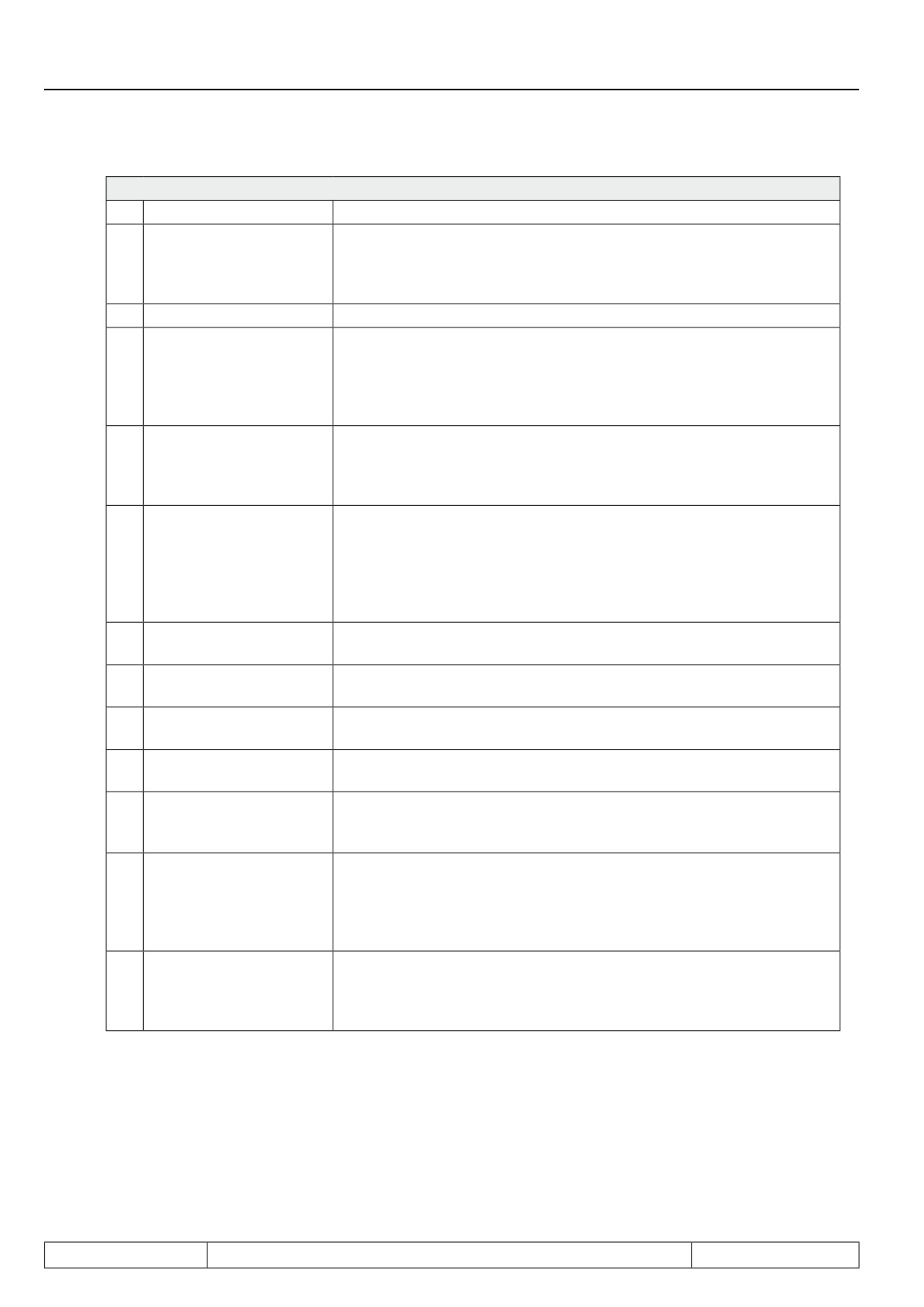
Functions and displays for the positioning mode
This chapter provides a compressed summary of the possibililties for control and visualisation of the positio-
ning mode. Some of the parameters and functions are described in more detail in the corresponding chapters
Input functions (di.11...di.22)
No.
Name
Function
24
Activation positioning/ syn-
Activation of the positioning mode
chronous
29
Start positioning
Start of the positioning
Input "+" functions (di.24...di.35)
2
Store position (teach)
Positive edge stores an actual position as the target position in PS.24
Positive edge stores the actual position in parameter ru.71. Can be used
3
Scan position
for visualisation and generation of digital output signals.
4
Relative position F/R
Rotation setting for relative positioning (if selected in PS.27)
For connecting an adjustment sensor for flying referencing with adjust-
7
Reference point correction
ment.
Display parameters
Parameter
Function
Display of the actual position (calculated from the position informa-
ru.54
Actual position
tion of the encoder interface, selected in PS.01).
The position that the drive is supposed to have reached currently,
ru.56
Set position
according to the calculated profile (in contrast to ru.61 "target posi-
tion", to be reached at the end of the positioning).
7
ru.58
Angle difference
Difference between set and actual position.
ru.60
Act. position index
Number of the positioning block currently being processed.
The target which the drive should reach at the end of the positio-
ru.61
Target position
ning.
Maximum value of the speed profile the inverter calculates for opti-
ru.63
Profile speed
mal target approach.
The value by which the actual position is adjusted during the "flying
ru.69
Distance ref.-zeropoint
referencing with adjustment".
Position value scanned by a digital input (used for digital output and
ru.71
Teach / scan position
teaching).
If the drive rotates at the time of the "start positioning" command
(vector controlled operation or new pulse during a running positio-
ning), this parameter shows what distance to the actual position
ru.84
Accessible rel. position
the target must be to be reachable with the programmed ramp and
S-curve times. The ramp adjustment (PS.32) is not considered (see
chapter 7.12.4.13 "start positioning").
Page7.12 - 73
Positioning and Synchronous Control
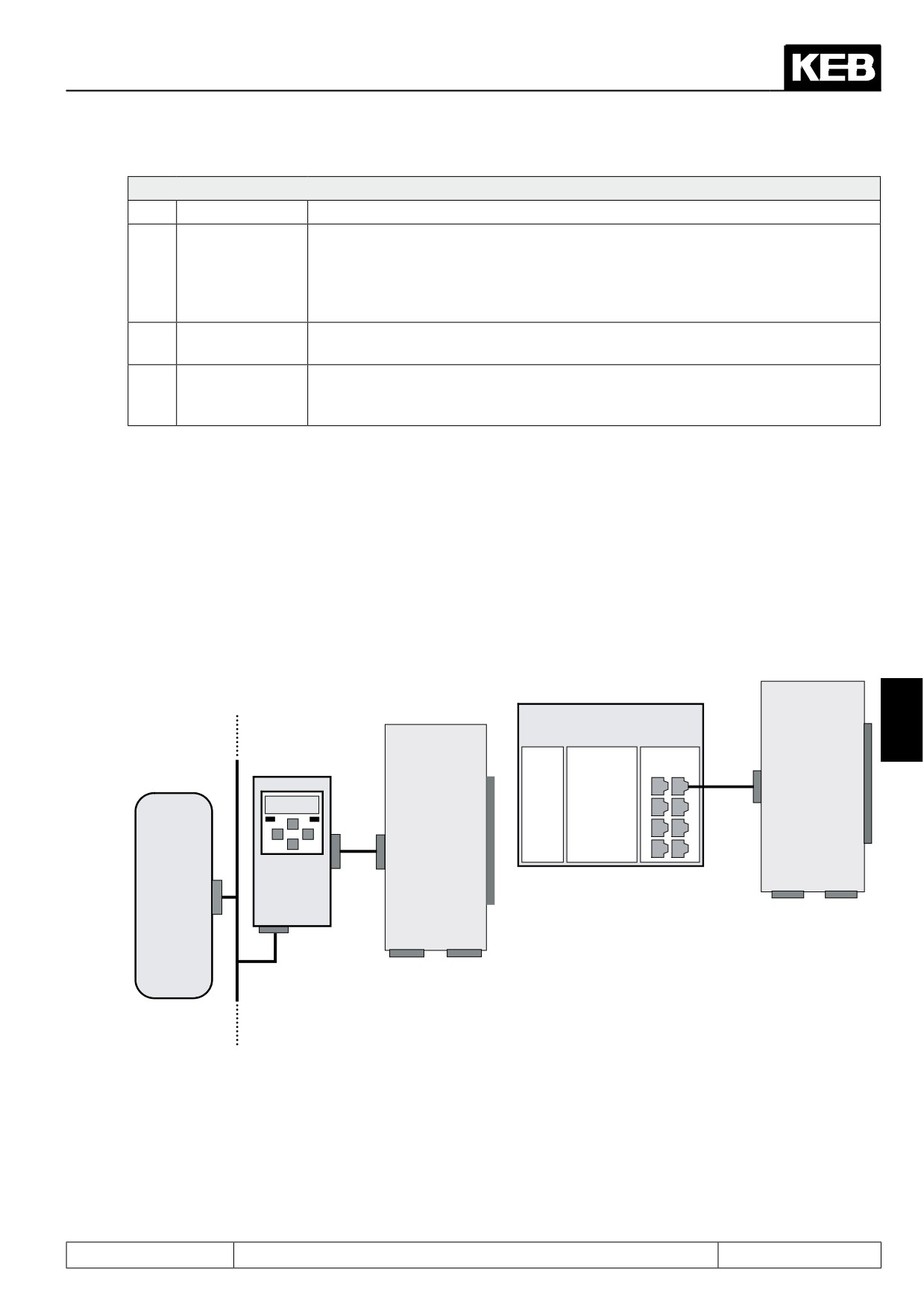
Output switching conditions (do.00...do.07)
39
Angle difference > level
Angle difference ru.58 > comparison level (LE.00...LE.07)
The position profile is completed (ru.56 = ru.61) and the drive is in the
range of +/- PS.30 / 2 (target window) around the target position ru.61.
54
Target window reached
Is also set if the drive is stopped at an intermediate target during the se-
quential (index) positioning.
55
Current position > level
Actual position ru.54 > comparison level (LE.00...LE.07)
Positioning is active, but the set position ru.56 has not yet reached the
target position ru.61. The output is deactivated as soon as the calculated
56
positioning active
position profile reaches the target position, even if the drive has not stop-
ped in the target window yet. For the sequential positioning, the output is
deactivated if the drive has stopped at the target of a positioning block.
The position is inaccessible from the current speed in compliance with
the adjusted deceleration and S-curve times, or a new "start positioning"
57
position not reachable
command was given during the deceleration ramp (see chapter 7.12.4.14
"inaccessible positions"). PS.00 determines the behaviour of the drive.
This output switching condition is needed for the follow-up positioning.
The output is set with "start positioning". If the drive has reached the
target position of a positioning step, the output remains set (in contrast
58
Profile processing active
to Nr. 56). Only when the set position (ru.56) reaches the position of the
last block (PS.24), the output is deactivated again. In the last block, in
parameter PS.26 "next index", the value " -1: PS.28" must be entered.
path traversed since the last "start positioning" command is greater than
67
travelled path > level
the switching level.
Position to the target win-
path still to be travelled until reaching the target window is greater than
68
dow > level
the switching level.
Actual position index
=
For sequential positioning: the current position index is equal to the swit-
72
level
ching level (scaling factor: values of 0.51...1.5 count as index 1 etc.).
Amount act. position
-
Actual position (ru.54) - teach/scan position (ru.71) > comparison level
75
scan position > level
(LE.00...LE.07)
The output is set if the switching condition "target window reached" is
Actual Position = position
77
met (see Nr. 54) and the "act. position index" (ru.60) is equal to the "start
index PS.28
index new profile" (PS.28).
Only an initiator pulse within the position window of +/- PS.40 around the
reference point PS.17 may trigger an adjustment. If a pulse is received
Rotary table reference in-
78
outside of this window, it is interpreted as an interference pulse and is
valid
ignored. With this output switching condition, the user can recognize the
presence of invalid pulses.
The output is set if a "start positioning" command is ignored because the
Ignore position not reach-
new target position is "inaccessible" (see chapter 7.12.4.14 "inaccessible
79
able
positions"). The output is reset by a new "start positioning" command or
by deactivation of the positioning mode.
The switching level for the switching conditions are set in LE.00...LE.07. Since the switching level can be used
for very different quantities (current, voltage, speed, position, etc.), they have the following scaling factors for
comparisons with position values:
LE.00...LE.07 = 1,00 → comparison level is 100 increments
Page7.12 - 74
Positioning and Synchronous Control
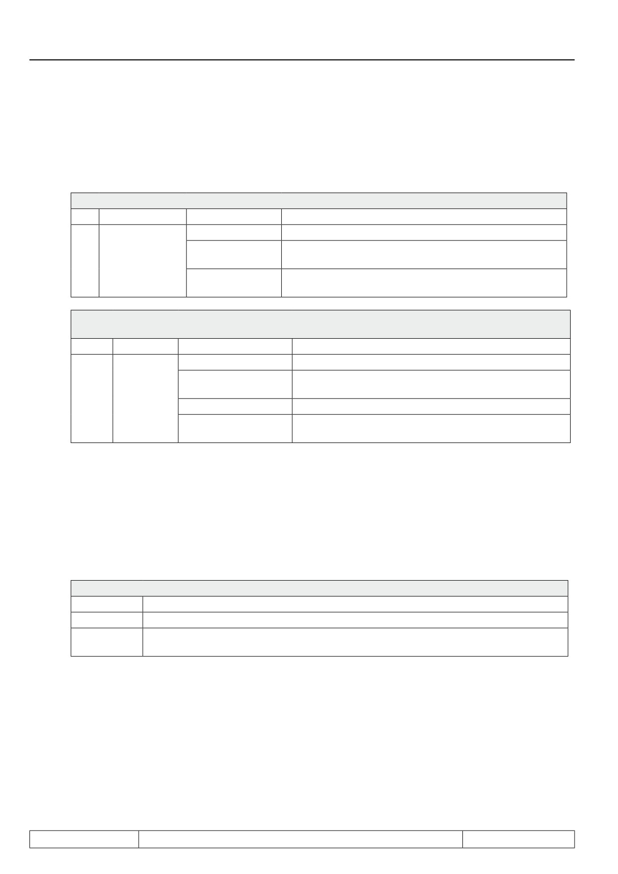
Inverter state (ru.00)
No
Name
Function
Display of activation of the positioning mode (input "posi/sync activation" active
and positioning mode selected in PS.00). Whether the position controller is al-
Ready for posi-
121
ready active (i.e., whether the first "start positioning" command has been given),
tioning
or whether the drive is still in vector controlled operation, is not indicated by this
display. Missing limit switch signals also do not affect the status display.
Positioning
Positioning profile (position / speed profile) is being calculated. The set point posi-
122
active
tion ru.56 has not reached the target position ru.61 yet.
The position is inaccessible from the current speed under the restrictions of the
Position not
123
adjusted deceleration and S-curve times or a new "start positioning" command
reachable
was sent during the deceleration ramp.
7.12.5Contouring control mode
7.12.5.1
Contouring control mode / premises
For the contouring control mode, the bus-synchronous operation must be activated. Bus-synchronous operati-
on means that a control sends telegrams in a constant time pattern and that all connected inverters synchronise
to this pattern. This allows angular-synchronous and multi-axis operation, respectively.
To implement the bus-synchronous operation, one requires either a fast fieldbus system with the associated
KEB-operator or a fast control supporting the HSP5-protocol (e.g., a drive control COMBICONTROL C5).
The following bus systems are supported: CAN, SERCOS, EtherCAT, Powerlink, HSP5.
Fieldbus
KEB inver-
(e.g. CAN, SERCOS,
ter
EtherCat, Powerlink)
COMBICONTROL
7
F5A-S
KEB inverter
C5
or
optional
fieldbus
Drive
F5A-M
interface
interface
F5A-S
or
RS232
Parametrisation
F5A-M
digital
HSP5
I/O
Ethernet
Bus
Parametrisation
Visualisation
X3B
X3A
Encoder
Encoder
channel 2
channel 1
KEB
operator
X3B
X3A
Customer
Encoder
Encoder
control
channel 2
channel 1
type
How the bus-synchronous operation is realised and initialised depends on the fieldbus system used and must
be looked up in the instructions for the corresponding operator (CAN-operator, SERCOS operator, etc.). The
inverter enters the mode "bus-synchronous operation" if a value unequal to zero is set in parameter Sy.08 "bus
synchronisation time" .
Note: As soon as the control sends cyclic telegrams in the pattern set in Sy.08, the bit 9 "HSP5 bus synchro-
nous" is set in the status word (Sy.51). The synchronous communication can be monitored with this bit. The
control release may only be given if the assembly of the bus-synchronous operation is completed.
Page7.12 - 75
Positioning and Synchronous Control
7.12.5.2
Contouring control mode / settings
All parameters can be specified in bus-synchronous operation. Typically, however, this operating mode is used
for the contouring control mode. The activation of this mode is done in parameter PS.00 or via the control
word.
PS.00: Posi / synchronous mode
Bit
Meaning
Value
Explanation
0...5
Without function for contouring control
6: Contouring con-
Posi-/Synchro-
Selection of operating mode contouring control
0..2
trol
nous mode
The operating modes are selected via the control word (Sy.43
7: Via control word
or Sy.50).
Sy.50: Control word (low) /
Sy.43: control word (long)
Bit
Meaning
Value
Explanation
0: off
4096: Synchronous
Selection of operating mode synchronous running
Operating
running
12 / 13
mode
8192: positioning
Selection of operating mode positioning
12288: Contouring
Selection of operating mode contouring control
control
To activate the contouring control mode, the digital input occupied with the function "positioning / synchronous"
must be set.
In contouring control mode, the drive is positioned via the setting of a position setpoint value in the bus-syn-
chronous grid. The control, therefore, does not give the final target position but the set point position for each
individual cycle.
The inverter calculates the speed required to reach the position setpoint in one bus cycle. The setting of the
position setpoint can be done via PS.24 "index position" or via PS.34 "contouring mode position".
PS.33 "source contouring mode position" determines which parameter provides the setpoint position.
PS.33: Source contouring mode position
Value
Explanation
0:PS.34
The position is adopted as the setpoint position only if PS.34 is written to.
1:PS.24 or
The value is adopted as the setpoint position if PS.24 or PS.34 are written to. This setting is
PS.34
reasonable if a switch between positioning and countouring mode is desired.
Page7.12 - 76
Positioning and Synchronous Control
7.12.5.3
Contouring control mode / write / read data
For the bus-synchronous operation, the read and write data that are to be transmitted with each bus cycle must
be defined. In the parameters Sy.24, Sy.26 and Sy.28, the bus addresses of the parameters that are to be pro-
vided bus-synchronously by the customer control must be set. Only 3 parameters (one 32 bit parameter and
two 16 bit parameters) can be selected.
For the contouring control mode, the setpoint position (32 bit parameter) must always be set bus-synchronous-
ly. To that end, the bus address of PS.34 (=1322h or 4898) or of PS.24 (= 1318h or 4888) must be entered in
Sy.24 "proc. write data 1 definition" (dependent on setting of PS.33).
The second parameter is typically occupied with the control word Sy.50 to allow driving the inverter as com-
pletely as possible via the bus.
Parameter Sy.43 "control word (long)" cannot be utilised because only a 16 bit parameter may be used. As a
third parameter, oP.03 "reference setting" can be used in case switching from contouring control mode to vector
controlled operation is to be possible.
Sy.24 proc. write data 1 definition = 1318h or = 1322h
Sy.26 proc. write data 2 definition = 32h
Sy.28 proc. write data 3 definition = 303h
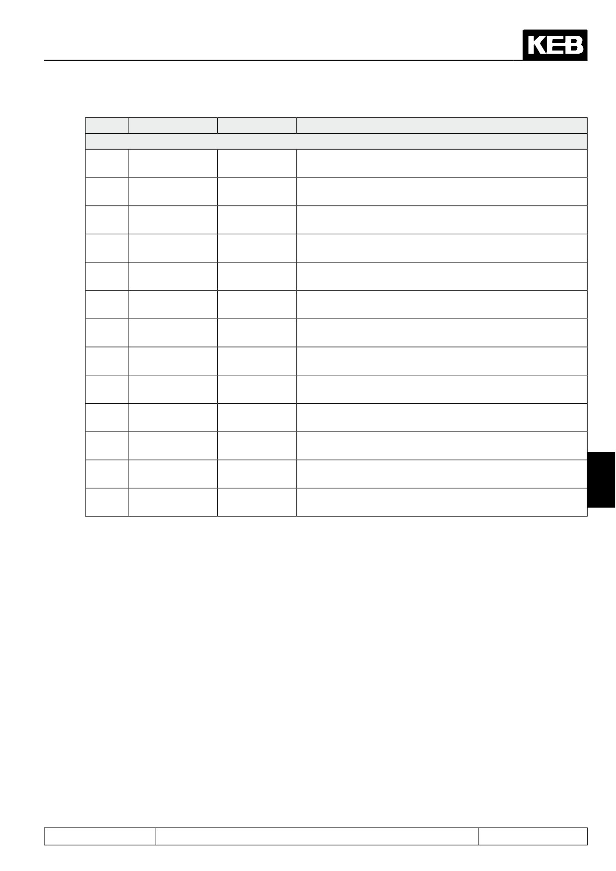
In the parameters Sy.16, Sy.18 and Sy.20, the bus addresses of the parameters that are to be read bus-syn-
chronously from the customer control must be set.
Again, 3 parameters (one 32 bit parameter and two 16 bit parameters) can be selected.Which parameters are
to be read depends on the application. Typically, however, ru.54 "actual position" (32 bit parameter) and Sy.51
"status word (low)" (16 bit parameter) are always read.
Sy.16 proc. read data 1 definition = 236h
Sy.18 proc. read data 2 definition = 33h
7.12.5.4
Contouring control mode / speed precontrol
With activation of the countouring module, the act. position value (ru.54) must be read once and then be trans-
7
mitted three times as the setpoint. This is necessary to initialise the drive-internal speed pilot control.
The same setpoint must also be transmitted three times to stop the drive, e.g., before ending the bus-synchro-
nous operation. This sets the speed pilot control to zero.
When setting the position setpoints, one must ensure that the drive will be able to follow them with the maxi-
mum permissible speed. Only oP.14 "absolute maximum reference forward" and oP.15 "absolute maximum
reference reverse" function as speed limits.
7.12.5.5
Contouring control mode / watchdog
A breakdown of the bus system is particularly critical during bus-synchronous operation. Therefore, bus moni-
toring should always be activated. To that end, a value unequal to 6 must be programmed in parameter Pn.05
"watchdog response" .
In Sy.09 "HSP5 watchdog time", the monitoring time for the HSP5 connection between inverter and operator
can be adjusted. The value "0:off" means that the watchdog is not active. In Pn.06 "watchdog time", the moni-
toring time of the fieldbus connection is parametrised. The actual monitoring of the fieldbus is carried out by the
operator. With the parameter Pn.05 "E.buS stopping mode", one selects how the drive responds (e.g., immedi-
ate error message or quick stop) to the occurence of a bus breakdown (HSP5 or fieldbus).
Page7.12 - 77
Positioning and Synchronous Control
7.12.5.6
Contouring control mode / example
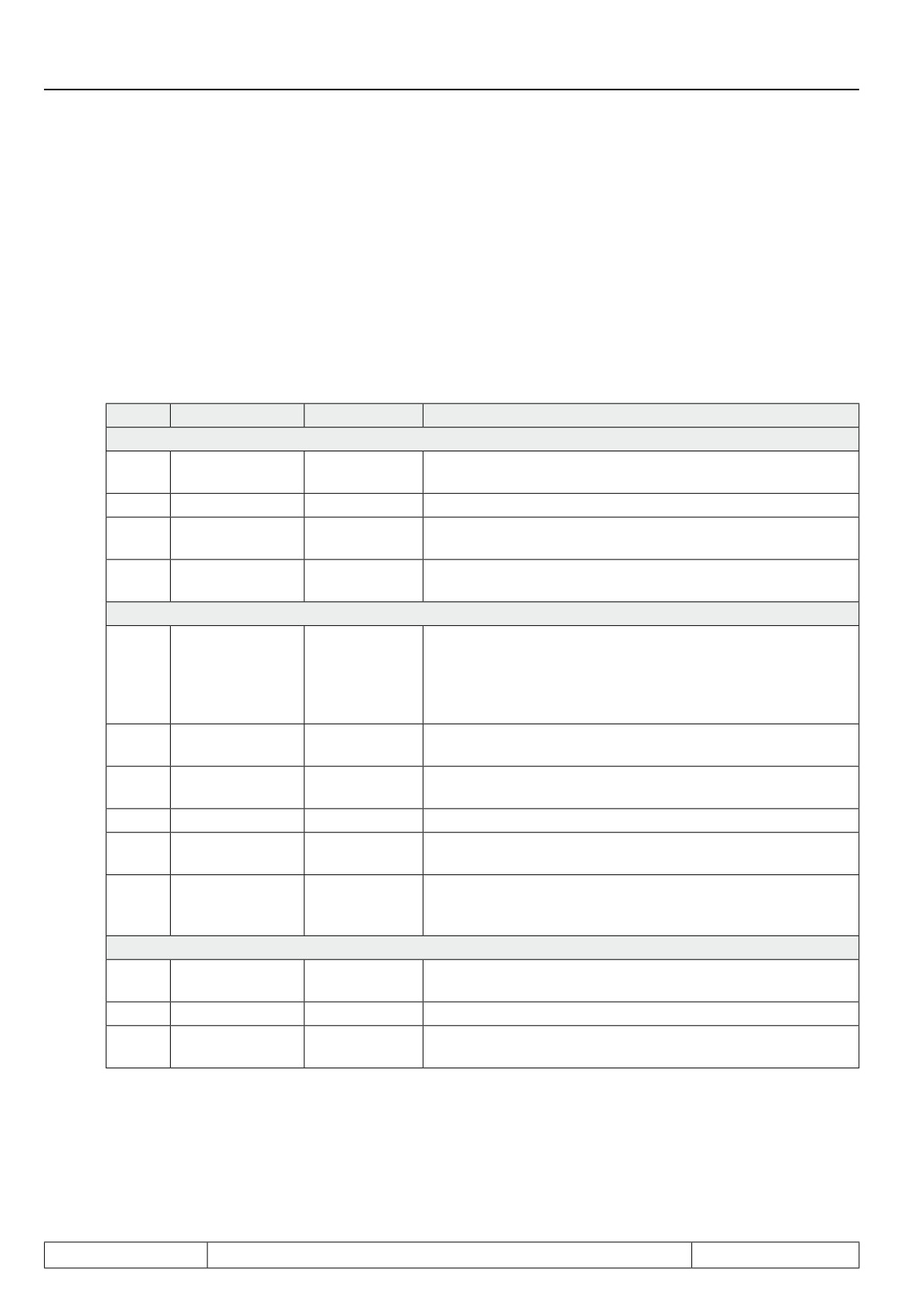
The drive shall meet the following requirements:
-
Position specification via PS.34
-
Speed specification via oP.03 if "0: off" is entered in "operating mode" (bit 12/ 13) of Sy.50 "control word
(low)"
-
Activation of the contouring mode via control word
-
bus synchronisation time 1000 µs
Parameter list:
Para.
Name
Value
Notice
General setting
Speed control
4: Speed con-
cs.00
Speed-controlled operation
configuration
trol
cs.01
Actual source
0: Channel 1
Speed feedback channel 1
2: digital abso-
oP.00
reference source
speed setpoint setting via oP.03
lute (op.3)
7: only setpoint
Direction of rotation from the setpoint sign, if the contouring
oP.01
Rotation source
sign
control mode is not activated
Settings for the position control in contouring control mode
Activation of the contouring mode via the control word (SY.50)
Attention: If the contouring mode is not activated in the control
Posi / synchro-
7: Via control
PS.00
word, the position value from encoder channel 1 is displayed
nous mode
word
in ru.54 "actual position". Thereby, the software limit switch
function, e.g., is not useable
Act. master
PS.01
1: Channel 2
Position feedback channel 2
source
Posi/synch input
If the contouring mode is selected in the control word, it is also
PS.02
1:ST
selection
immediately active
PS.06
KP pos/syn
100
Kp value for the position controller
Mode of position
The acquired position is valid (absolute encoder/ no approach
PS14
128
ref.
to reference point necessary)
Source con-
Position setpoint in the contouring control mode is set via
PS33
touring mode
0:PS.34
PS.34
position
Bus monitoring
HSP5 watchdog
Sy.09
0,01 (10ms)
smallest adjustable monitoring time
time
Pn.06
Watchdog time
0,01 (10ms)
smallest adjustable time for field bus monitoring
E.buS stopping
Pn.05
1
Quick stop/ modulation off/ no auto restart
mode
Page7.12 - 78
Positioning and Synchronous Control
Para.
Name
Value
Notice
Parametrisation of the bus-synchronous operation
Proc. read data 1
Sy.16
0236h
read ru.54 "Actual position"
definition
Proc. read data 1
Sy.17
1
Value immaterial since parameter is not set-programmable
set
Proc. read data 2
Sy.18
0033h
read SY.51 "status word (low)"
definition
Proc. read data 2
Sy.19
1
Value immaterial since parameter is not set-programmable
set
Proc. read data 3
Sy.20
-1: off
definition
Proc. read data 3
Sy.21
1
No third read parameter defined
set
Proc. write data 1
Sy.24
1322h
write PS.34 "Contouring mode position"
defin.
Proc. write data
Sy.25
255
Value immaterial since parameter is not set-programmable
1 set
Proc. write data 2
Sy.26
0303h
write oP.03 "reference setting"
defin.
Proc. write data
Sy.27
255
The value of oP.03 is adopted in all sets
2 set
Proc. write data 3
Sy.28
0032h
write SY.50 "control word (low)"
defin.
Proc. write data
Sy.29
255
Value immaterial since parameter is not set-programmable
3 set
7
Bus synchronisa-
Is written via the customer control or the COMBICONTROL
Sy.08
1000 us
tion time
C5
Page7.12 - 79
Positioning and Synchronous Control
7.12.6Position controller
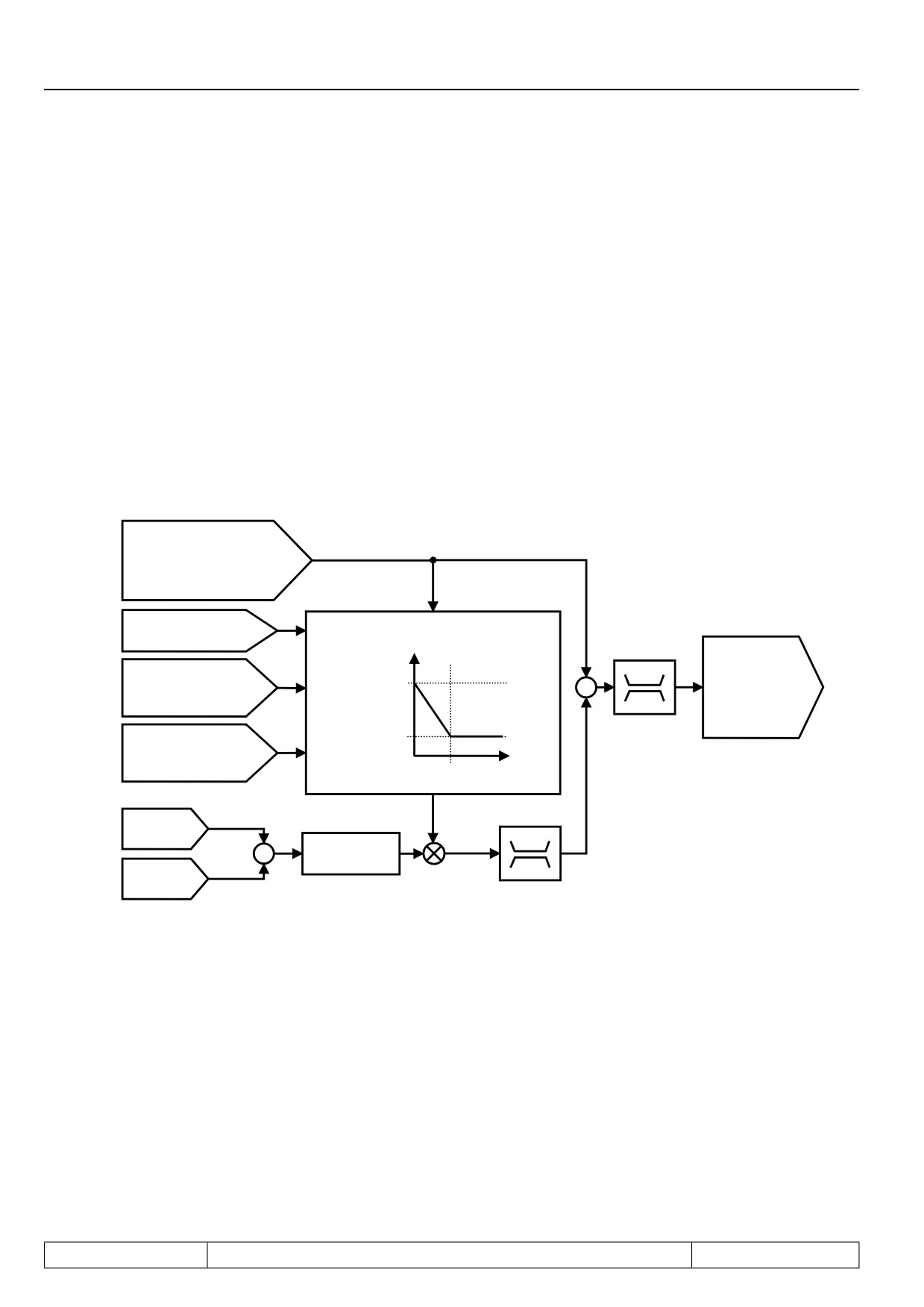
The position controller is built as a P-controller. The increments per revolution of the encoder and the resolution
of the speed is considered in the controller. When swapping the encoder (e.g., from 1024 => 2500 increments)
or changing the speed range (e.g., from the 4000 to the 8000 speed mode by changing the parameter ud.02
"control type"), the speed controller setting can be applied.
The Kp of the position controller can be changed speed-dependently. Thereby, one can, e.g., choose a very
hard setting for the load transfer and the approach to the final position. For the remaining positioning,
the Kp is then lowered to achieve quiet operation of the drive and to dampen the effects of mechanical distur-
bances (like, e.g., seams in guide rails or similar).
The base value of the controller is set in PS.06 "KP positioning / synchronous". Parameter PS.08 "speed limit
for PS.07" determines up to which speed the lowering is to be implemented, and parameter PS.07 "KP speed
limit reduction" determines the percentage value the Kp shall still have in relation to its base value at the speed
PS.08.
The following figure illustrates this structure:
positioning module:
ru.63 Profile speed
Synchronous module:
ru.10 Encoder 2 speed
PS.06
oP.14 / oP.15
Kp position controller
absolute max.
Kp pos/syn
Setpoint value
ru.02
ramp output display
PS.07
+
PS.06
Kp speed limit reduction
(setpoint speed for
+
speed controller)
PS.07
PS.08
* PS.06
100 %
Speed limit
for PS.07
Speed
PS.08
KP
ru.56
Set position
+
ru.58
Angle difference
ru.54
-
Actual position
PS.09
Position limit
Posi/synchronous
Page7.12 - 80
Protective Functions
7.1
Operating and appliance data
1.
Introduction
7.2
Analog in- and outputs
2.
Summary
7.3
Digital in- and outputs
3.
Hardware
7.4
Setpoint-, rotation- and ramp adjustment
Motor data and controller adjustments of the asynchronous
7.5
4.
Operation
motor
Motor data and controller adjustments of the synchronous
7.6
motor
Selection of Operating
5.
Mode
7.7
Speed control
6.
Initial Start-up
7.8
Torque display and -limiting
7.9
Torque control
7.
Functions
7
7.10
Current control, -limiting and switching frequencies
8.
Error Assistance
7.11
Speed measurement
9.
Project Design
7.12
Positioning and synchronous control
7.13
Protective functions
10. Networks
7.14
Parameter sets
11. Parameter Overview
7.15
Special functions
12. Annex
7.16
CP-Parameter definition
Page7.13 - 1
Protective Functions
7.13.1
Error and warning messages
7.13 - 3
7.13.1.1
Undervoltage
7.13 - 4
7.13.1.2
Overvoltage
7.13 - 4
7.13.1.3
Overcurrent
7.13 - 4
7.13.1.4
Overload
7.13 - 4
7.13.1.5
Inverter over temperature
7.13 - 5
7.13.1.6
External fault
7.13 - 5
7.13.1.7
Bus error
7.13 - 5
7.13.1.8
Limit switch error
7.13 - 6
7.13.1.9
Motor protection with temperature sensor
7.13 - 7
7.13.1.10
Software motor protection
7.13 - 7
7.13.1.11
Set selection error
7.13 - 7
7.13.1.12
Encoder interface / encoder error
7.13 - 8
7.13.1.13
Speed limit exceeded
7.13 - 8
7.13.1.14
Speed controller limit reached
7.13 - 9
7.13.1.15
Maximum acceleration exceeded
7.13 - 9
7.13.1.16
General power circuit error
7.13 - 9
7.13.2
Response to malfunction messages
7.13 - 10
7.13.2.1
Selection of the response
7.13 - 10
7.13.2.2
Parametrisation of the abnormal stopping
7.13 - 12
7.13.3
Automatic restart
7.13 - 15
7.13.3.1
Undervoltage error (E.UP)
7.13 - 15
7.13.3.2
Overvoltage error (E.OP)
7.13 - 15
7.13.3.3
Overcurrent error (E.OC)
7.13 - 15
7.13.3.4
Malfunction messages and pre-warnings
7.13 - 16
7.13.4
Base block
7.13 - 16
7.13.5
Quick Stop
7.13 - 16
7.13.5.1
Quick stop in the V/F characteristic operation
7.13 - 17
7.13.5.2
Quick stop at closed-loop systems
7.13 - 18
7.13.5.3
Time monitoring abnormal stopping
7.13 - 19
7.13.5.4
Abnormal stopping via control word
7.13 - 19
7.13.6
Speed search
7.13 - 19
7.13.6.1
Speed search in the open loop operation
7.13 - 20
7.13.6.2
Speed search at asynchronous motors in the closed-loop
operation with encoder
7.13 - 20
7.13.6.3
Speed search at asynchronous motor in the closed-loop operation
without encoder (ASCL)
7.13 - 20
7.13.7
LAD-stop
7.13 - 20
7.13.7.1
Current-dependent ramp stop
7.13 - 21
7.13.7.2
DC link voltage-dependent ramp stop
7.13 - 21
7.13.7.3
Ramp stop dependent on a digital input
7.13 - 21
7.13.8
Current limit constant run (stall function)
7.13 - 22
7.13.9
Motor Protection Mode
7.13 - 25
7.13.10
Power-Off function
7.13 - 29
7.13.11
GTR7-Control
7.13 - 35
7.13.11.1
Activation via digital input
7.13 - 35
7.13.11.2
Adjustment of the activation threshold
7.13 - 35
7.13.11.3
Activation conditions
7.13 - 36
7.13.12
Special functions
7.13 - 36
Page7.13 - 2
Protective Functions
7.13 Protective functions
The protective functions protect the inverter against switch off caused by overcurrent, overvoltage as well as
thermal overheating. Furthermore, you can restart the drive after an error automatically (Keep-On-Running).
7.13.1Error and warning messages
For diagnostic purposes, the inverter displays various malfunction- and error messages. Errors are all those
events that trigger an immediate switch-off of the modulation, malfunctions allow a defined response (shutdown
of the drive by abnormal stopping).
For some events (ext. error, bus monitor response, the drive hitting a limit switch, etc.), one can decide in the
programming whether this is an error or a malfunction.
For some errors, e.g., the overload error, a pre-warning can be generated. This pre-warning is treated like a
malfunction, i.e., the appropriate response to the pre-warning is programmable.
Example 1 (error):
The inverter detects overcurrent and raises the error. Display in parameter ru.00: "Error! Overcurrent" (E. OC).
Since this error cannot be predicted, there is no possibililty of a pre-warning. The modulation is switched off
immediately and the drive spins down.
Example 2 (operating condition programmed as error):
The reaction of the bus monitor ("watchdog") shall trigger an error. Programming Pn.05: "E.buS stopping mode"
= 0 (error / no auto restart). Display in parameter ru.00: "Error! Watchdog" (E. buS). If a digital output is pro-
grammed on a fault signalling relay, the relay switches.
Example 3 (operating condition programmed as malfunction):
7
Hitting a hardware limit switch shall be treated as a malfunction. Desired response: Abnormal stopping, modu-
lation switch-off after reaching standstill, no automatic restart.
Programming Pn.07: "Proh. rotation stopping mode" = 1 (Stop / modulation off / no auto restart)
Display in parameter ru.00: "Warning! disabled direction of rotation clockwise" (A.PrF) or: "Warning! disabled
direction of rotation counter clockwise" (A.Prr)
If a digital output is programmed on a fault signalling relay, the relay does not switch by default.
(If the digital output shall also respond to malfunctions, switching condition 6 "abnormal stopping / error" must
be used. Alternatively, Pn.65 can be adjusted so that a malfunction is treated like an error with respect to the
status displays and the digital outputs. See chapter 7.13.12)
Example 4 (pre-warning):
When the heat sink temperature exceeds a limit (dependent on the inverter type), the modulation is switched
off, the inverter raises an error. With Pn.11 "OH warning level" a temperature can be set at which a pre-warning
is generated.
Desired response: when exceeding the temperature of Pn.11,. the inverter executes an abnormal stop and swit-
ches off the modulation. When the heat sink temperature decreases again, an automatic restart shall occur.
Programming Pn.10 "Warning OH stopping mode" = 4 (stop/modulation off/ auto restart).
Display in parameter ru.00: "Warning! Heat sink temperature" (A. OH)
If the temperature decreases due to the abnormal stopping, the inverter executes an automatic restart. If, howe-
ver, the heat sink temperature continues to rise and exceeds the error limit, the inverter raises an "Error! Heat
sink temperature" (E. OH).
Page7.13 - 3