KEB COMBIVERT F5-A,-E,-H 4.0. APPLICATION MANUAL (2008) - page 17
Positioning and Synchronous Control
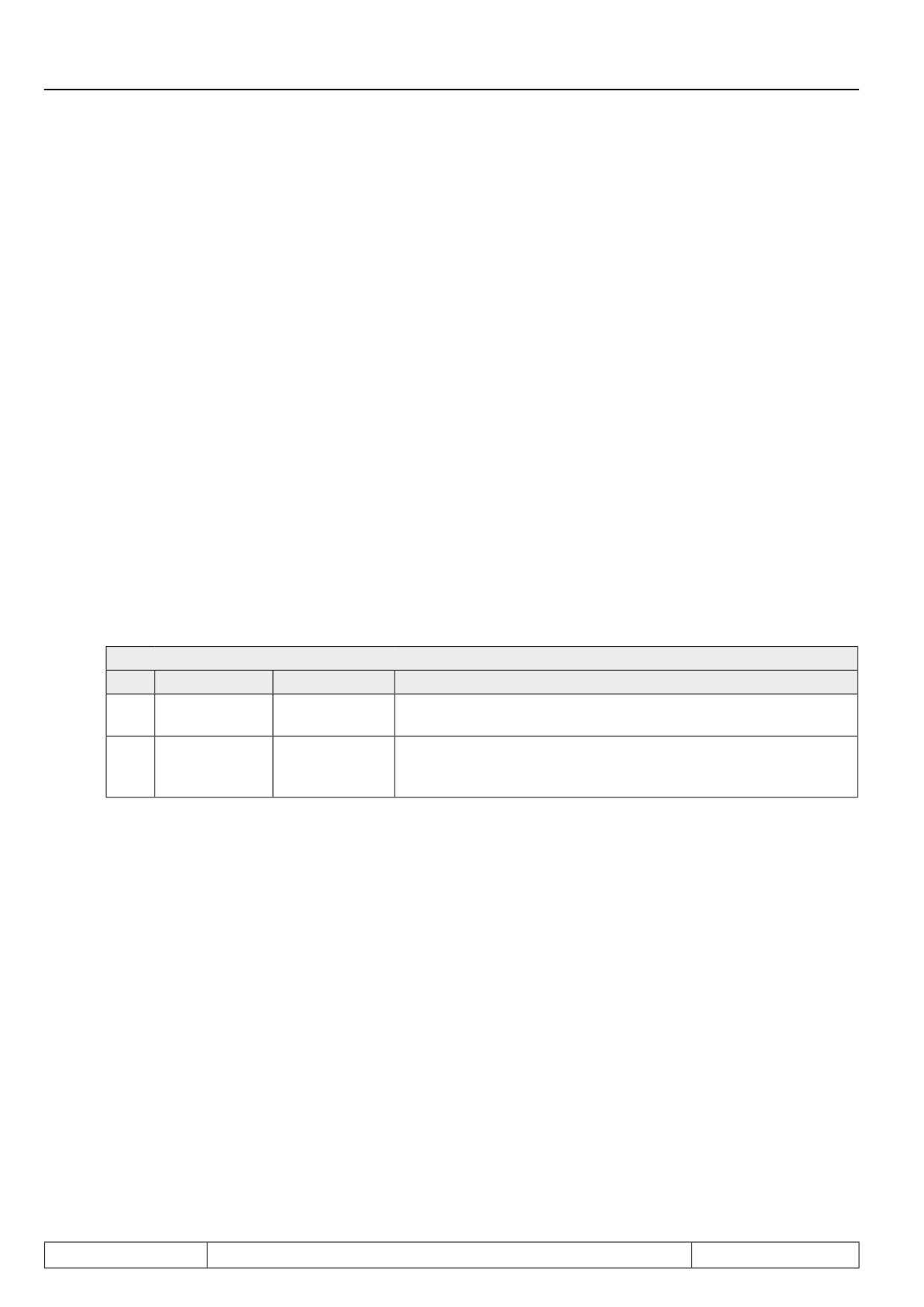
Example 3: Positioning of a workpiece for various processing steps / sequence control by external control /
analog setting of the maximum profile speed
Sequential positioning with stop between the positioning steps and definition of the profile speed by PS.31.10
Settings:
● The drive shall stop at each position to allow processing of the workpiece, until the external control gives
the signal to continue, i.e., "start positioning". The external signal comes from input I3. The drive shall
signal the control via an output that it has reached the current target with an accuracy of 10 increments,
so that the processing can begin.
The maximum profile speed shall be set via the analog input AN2 (X2A.3 / X2A.4):
● Let the position at which the workpiece starts have the value 0.
● The first stop shall be at position 100,000.
● The second stop shall be at position 200,000.
● After that, the drive shall return to its starting position
Adjustments:
● PS.00:
PS.00: Posi / synchronous mode
Bit
Meaning
Value
Explanation
Posi / synchro-
0...2
5: Posi mode
Activation of the positioning mode
nous mode
The maximum profile speed is set via PS.31 "max. speed setting
Positioning /
16:PS.31 /
4
%". The drive is to stop at the target, so the target speed must be
target speed
PS.25
PS.25 = 0 for all blocks.
All other bits can remain at the factory settings for this example and are explained in the following chapters.
● Block 0 defines the start position
→ PS.28 = 0
● Input I3 serves as "start positioning"
→ PS.29 = 64: I3 (X2A.12)
● The maximum profile speed is calculated from:
PS.31 (max. speed %) x oP.10 (max. reference forward)
To change this by analog input via AN2, the following settings must be entered:
(also see chapter 7.15.10: analog parameter setting)
An.30: Sel. REF-inp./AUX-funct.
= 2112
(factory setting)
An.53: Analog para. setting source
= 0: AUX input (ru.53)
(factory setting)
An.54: Analog para. setting de-
= 131Fh
(bus address PS.31)
stination
An.55: Analog para. setting offset
= 0
(factory setting)
An.56: Analog para. setting max.
= 1000
value
oP.19: Step value input selection 1
= 1500 rpm
(max.possible profile speed)
Page7.12 - 44
Positioning and Synchronous Control
An.30 defines that AN2 serves as AUX input.
An.53 defines that the parameter value is set via the AUX input.
An.54 defines the bus address of the parameter to be set by analog input (here, PS.31)
(the bus address of a parameter can be read in Combivis in, e.g., the work list).
An.56 defines the maximum value (unnormalised) for parameter PS.31. The normalised value for PS.31
is then calculated as follows:
100% AUX value = maximum value (An.56) x resolution of the parameter PS.31 (0,1%) =
1000 x 0,1% = 100%
The value of PS.31 therefore corresponds to the AUX-value.
The maximum profile speed is then calculated as follows:
ru.63: Profile speed = PS.31 x oP.10 = AUX x oP.10
●
block 0
→ PS.23: Index selection = 0
Position = 0
→ PS.24: Index position = 0
Drive stops at target
→ PS.25 = 0 rpm
next positioning step defined in block 1
→ PS.26 = 1
no automatic start, i.e., "continuation of the profile processing" = 0: no and "position setting"
= 0: absolute
→ PS.27 = 0: no + absolute
7
●
block 1
→ PS.23: Index selection = 1
Position = first stopping point
→ PS.24: Index position = 100000
Drive stops at target
→ PS.25 = 0 rpm
next positioning step defined in block 2
→ PS.26 = 2
Wait for "start positioning"
→ PS.27 = 0: no + absolute
●
block 2
→ PS.23: Index selection = 2
Position = second stopping point
→ PS.24: Index position = 200000
Drive stops at target → PS.25 = 0 rpm
next positioning step back to start → PS.26 = 0
Wait for "start positioning" → PS.27 = 0: no + absolute
Page7.12 - 45
Positioning and Synchronous Control
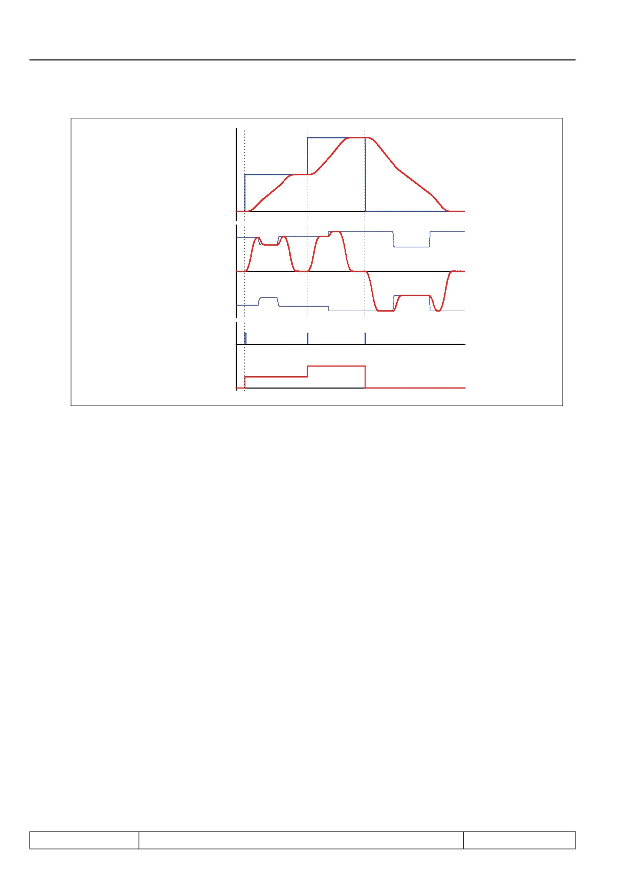
ru.61: Target
position
ru.54:Act.
position
ru.02: Ramp
output display
ru.63/ -ru.63
Profile speed
I3 (X2A.12) Start
positioning
ru.60: Act.
position index
Time
Change of the maximum profile speed is possible at all times. The speed / position profile for each positioning
step is adjusted permanently, so that the drive (in compliance with the acceleration and jolt setpoints) is positi-
oned at the maximum permitted speed.
Example 4: Positioning of a workpiece for various processing step / sequence control by timer-functionality and
the input / output handling of the inverter
Sequential positioning with stop between the positioning steps and definition of the profile speed by PS.25.
Note: this example requires detailed knowledge of the timer functionality and of the input / output handling.
These chapters must therefore be read prior to programming an internal sequence control system. If no internal
control is to be implemented, this example can be skipped.
Settings:
● The position at which the workpiece starts has the value 0.
● Driving to this position (whether after "power on", after error or as part of the positioning process) can
always occur at maximum speed = 1500 rpm.
● The first stop shall be at position 100,000. The profile speed up to that point shall be 1000 rpm. The stop
shall last 500 ms, and the drive shall continue automatically after that time. The drive shall signal the
control through an output that it has reached the target with an accuracy of 10 increments, so that the
processing can begin.
● The second stop shall be at position 200,000. Let the profile speed to that point again be 1000 rpm. The
stop shall last 1200 ms and the drive shall return to the starting position automatically after that time.
The drive shall signal the control through an output that it has reached target 2 with an accuracy of 10
increments, so that the processing can begin.
Page7.12 - 46
Positioning and Synchronous Control
Adjustments:
● PS.00:
PS.00: Posi / synchronous mode
Bit
Meaning
Value
Explanation
Posi / synchro-
0...2
5: Posi mode
Activation of the positioning mode
nous mode
Positioning /
0:PS.25 /
4
The maximum profile speed is set via PS.25 "Index speed".
target speed
PS.25
All other bits can remain at the factory settings for this example and are explained in the following chapters.
● Block 0 defines the start position
→ PS.28 = 0
● Input I3 serves as "start positioning"
→ PS.29 = 64: I3 (X2A.12)
● Target window size shall be 20 increments (= 2 x accuracy)
→ PS.30 = 20
Reaching of the target window shall be indicated by output O1:
→ do.00: Condition 0 = 54: target window reached (positioning)
→ do.16: Condition selection for flag 0 = 1: SB0
→ do.33: Flag selection O1 = 1: M0
● Implementation of the stops:
If the drive has reached position 1 (PS.24 of block 1) and position 2 (PS.24 of block 2), respectively, it
shall remain there 500ms and 1200ms, respectively, and then automatically carry out the next positio-
ning step. To implement this sequence, the timer functionality must be utilised. With reaching of the tar-
7
get of Index 0 or Index 1, Timer 1 must be started. The drive then remains at the target position until the
timer has exceeded the time level of 500ms and 1200ms, respectively. Exceeding the time level triggers
a "start positioning". With the start of the next positioning, the timer must be stopped and reset.
The start of the timer must be triggered by a software input. Input IA was chosen here.
→ LE17: Timer 1 start input selection = 256: IA
IA is always then set if software output OA is set.
On reaching of the target of Index 1 or Index 2, Timer 1 must be started (i.e., the software output OA must be
set).
Page7.12 - 47
Positioning and Synchronous Control
Output OA must also be set if the switching condition act.. index = 1 or act.. index = 2 and, simultaneously, the
condition "target reached" are met
→ do.00: Condition 0 = 54: target window reached (positioning)
M0 = SB0 = target reached
→ do.16: Condition selection for flag 0 = 1: SB0
→ do.01: Condition 1 = 72: act. position index = level
SB1: Index = 1
→ LE.01: Comparison level 1 = 1,00
→ do.02: Condition 2 = 72: act. position index = level
SB2: Index = 2
→ LE.02: Comparison level 2 = 2,00
→ do.19: Condition selection for flag 3 = 6: SB1+SB2
M3 = SB1 or SB2
→ do.37: Flag selection for OA = 9: M0+M3
OA = M0 and M3
→ do.41: AND connection for outputs = 16: OA
When the timer has counted 1500ms (for index 1) or 1200ms (for index 2), a "start positioning" signal shall
be generated.
As input for the "start positioning" signal, software input IB is used.
→ PS.29 = 576: I3 (X2A.12) + IB
Output OB must therefore be set, when the switching conditions index = 1 (SB1) and timer 1 > 500ms, or
index = 2 (SB2) and timer 1 > 1200ms, are met.
→ do.03: Condition 3 = 37: Timer 1 > level
SB3: Timer > 500 ms
→ LE.03: Comparison level 3 = 0,50
→ do.04: Condition 4 = 37: Timer 1 > level
SB4: Timer > 1200 ms
→ LE.02: Comparison level 2 = 1,20
→ do.17: Condition selection for flag 1 = 10: SB1+ SB3
M1 = SB1 and SB3
→ do.18: Condition selection for flag 2 = 20: SB2+ SB4
M2 = SB2 and SB4
→ do.24: AND connection for flags = 6: M1+M2
→ do38: Flag selection for OB = 6: M1+M2
OB = M1 or M2
The resetting of the timer must be triggered by a software input. Input IC was chosen here.
→ LE.19: Timer 1 reset input selection = 1024: IC
Output OC must therefore be set when the condition "target window reached" is not set.
→ do.31: Inv. flags for OC = 1: M0 OC = NOT M0
→ do.39: Flag selection for OC = 1: M0
● block 0
→ PS.23: Index selection = 0
Position = 0
→ PS.24: Index position = 0
Permitted max. speed = 1500 rpm
→ PS.25 = 1500 rpm
next positioning step defined in block 1
→ PS.26 = 1
Wait for "start positioning" command
→ PS.27 = 0: no + absolute
Page7.12 - 48
Positioning and Synchronous Control
● block 1
→ PS.23: Index selection = 1
Position = first stopping point
→ PS.24: Index position = 100.000
speed up to the first stopping point
→ PS.25 = 1000 rpm
next positioning step defined in block 2
→ PS.26 = 2
Wait for "start positioning" command
→ PS.27 = 0: no + absolute
● block 2
→ PS.23: Index selection = 2
Position = second stopping point
→ PS.24: Index position = 200.000
speed up to the second stopping point
→ PS.25 = 1000 rpm
Back to start
→ PS.26 = 0
Wait for "start positioning" command
→ PS.27 = 0: no + absolute
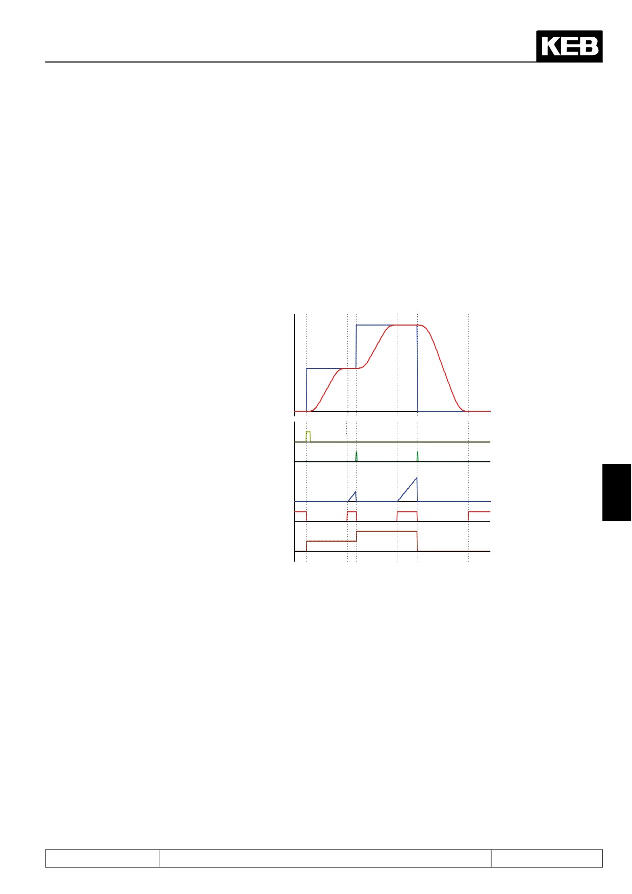
ru.61: Target position
ru.56: Set position
„Start positioning“
signal from external
control (I3)
Automatic generated
„Start positioning“
signal
ru.43: Timer 1 display
7
„Target reached“
signal
ru.60: Act. position
index
Page7.12 - 49
Positioning and Synchronous Control
7.12.4.9
Posi mode / Positioning with set changeover
In the positioning blocks, only target position, profile speed, traversal manner, and sequence of the positionings
are stored. To reach the acceleration /, deceleration time and the S-curves, one must use various sets.
Before the start of a positioning, that set must be activated which contains the desired acceleration and jolt
values.
If positions are to be connected directly with certain profiles, the set-programmability of the parameter PS.28
can be utilised.
set-programmable parameters
not set-programmable parameters
Set
PS.28
OP parameter
PS.23
PS.24
PS.25
PS.26
PS.27
0
0
Ramps and S-curve times (A)
0
Position (A)
Profile speed (A)
-1
no
1
1
Ramps and S-curve times (B)
1
Position (B)
Profile speed (B)
-1
no
2
2
Ramps and S-curve times (C)
2
Position (C)
Profile speed (C)
-1
no
3
3
Ramps and S-curve times (D)
3
Position (D)
Profile speed (D)
-1
no
I.e., in the 4 sets used, the required acceleration and S-curve times are programmed. In each set, a different
index is parametrised as the starting index.
7.12.4.10
Posi mode / rotary table
The round table positioning allows positioning within 360°.
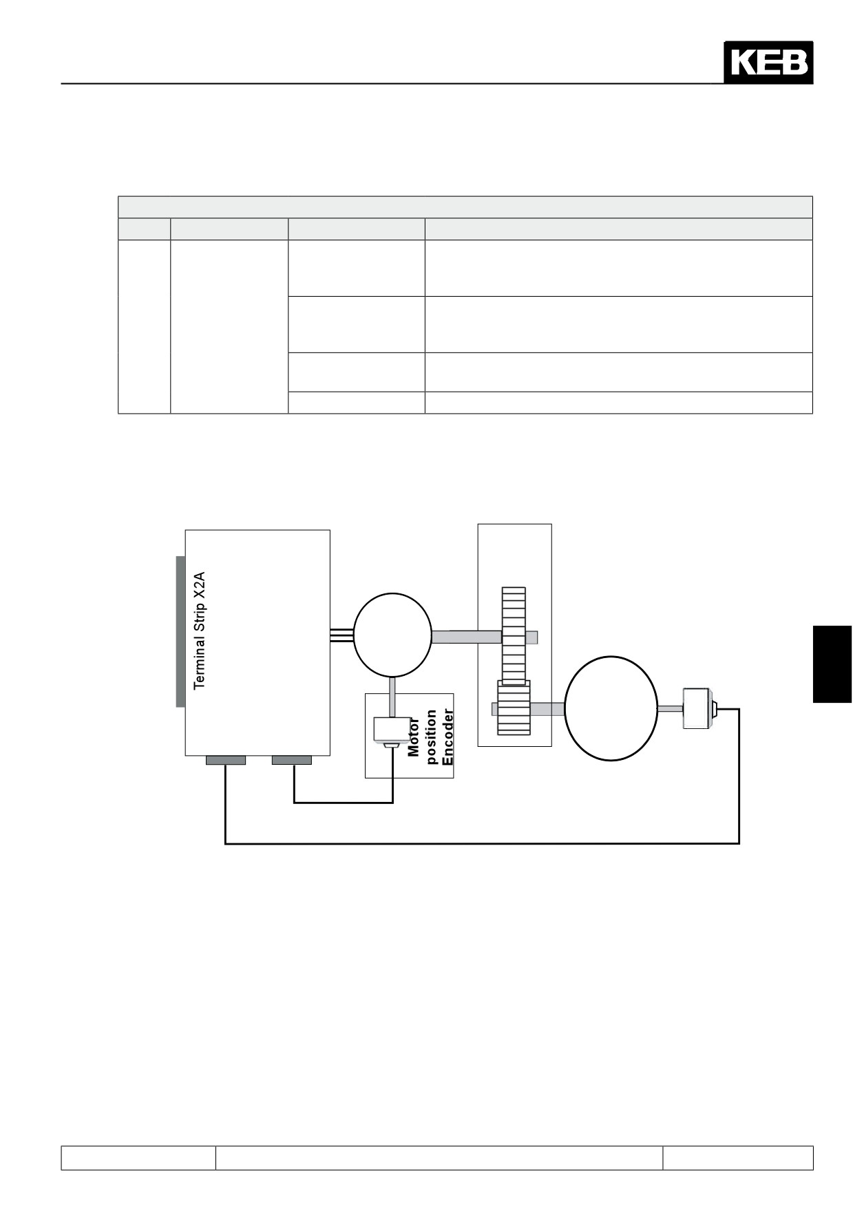
Parameter PS.39 "position range" gives the number of increments per one revolution of the round table. If the
position feedback is not connected to the round table but to the motor, the gear must also be considered.
Example:
The motor must execute 21 revolutions for the round table to complete one full revolution. Let the increments
per revolution of the incremental encoder on the motor be 2500 increments (parameter Ec.01) and in parameter
Ec.07 "encoder 1 trigger", the value 2 is: 4-fold programmed.
This results in:
PS.39 = 21 x 2500 x 22 = 210000
The actual position and the set point position vary only in a range of 0 to (PS.39 - 1).
Attention: Only positions from 0 to (PS.39 - 1) may be set as target position (PS.24).
Attention: The difference between set point position and actual position may never be greater than PS.39/2,
i.e., the drive may not be blocked!
Page7.12 - 50
Positioning and Synchronous Control
With PS.27, the general round table mode is selected:
PS.27: Index mode
Bit
Meaning
Value
Explanation
The position on the round table is always approached on the
8: Rotary table with
shortest path , i.e., the drive approaches the position from
path optimization
the right or the left.
10: Rotary table wi-
The position on the round table is always approached from
1...3
Position setting
thout path optimiza-
one direction. The sign of the position setpoint determines
tion
the direction of the positioning
12: Round table re-
The new target position is set relative to the current target
lative (round axis)
position.
0, 2, 4, 6, 14
Not for rotary table
The different round table modes were created for different applications.
7.12.4.10.1
Rotary table with path optimization
Control type
Gear
F5A-S
or
F5A-M
M
Rotary table
3~
position
7
Encoder
Rotary table
X3B
X3A
Encoder
Encoder
channel
channel 1
2
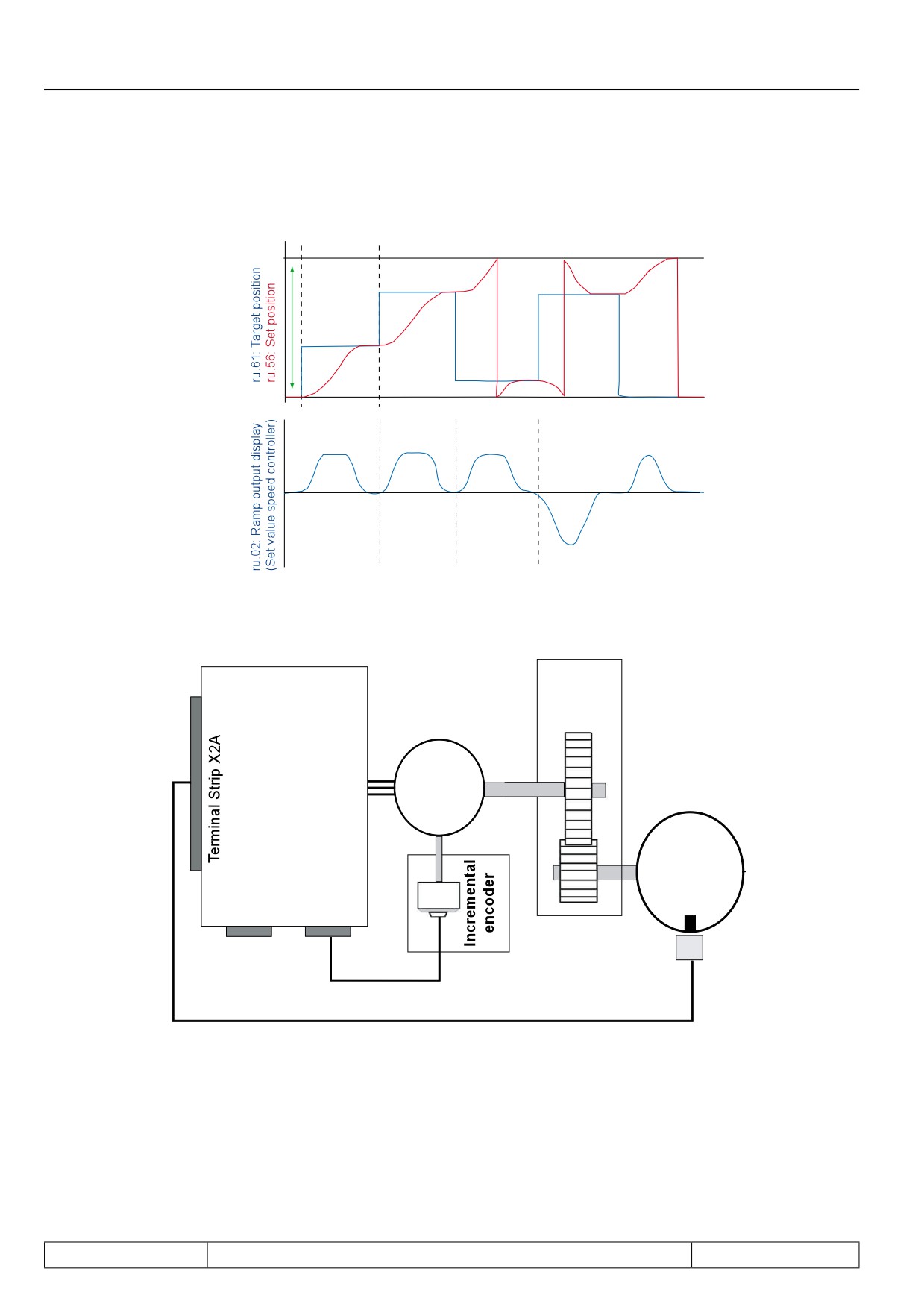
This mode is particularly suitable for round table applications where a second encoder is used for the round ta-
ble position. Here, the gear backlash cannot cause a position error, and the target position can be approached
precisely from both directions of rotation.
Here, the mode 8 "round table with path optimisation" is optimal since the shortest positioning times can be
achieved in this mode.
Page7.12 - 51
Positioning and Synchronous Control
It is a prerequisite that the round table permits rotations in both directions.
The target position may lie only in the range of 0 to PS.39 - 1.
Rotary table
range
7.12.4.10.2
Rotary table without path optimization
Control type
Gear
F5A-S
or
F5A-M
M
3~
Rotary
X3B
X3A
table
Encoder
Encoder
channel 2
channel 1
Initiator
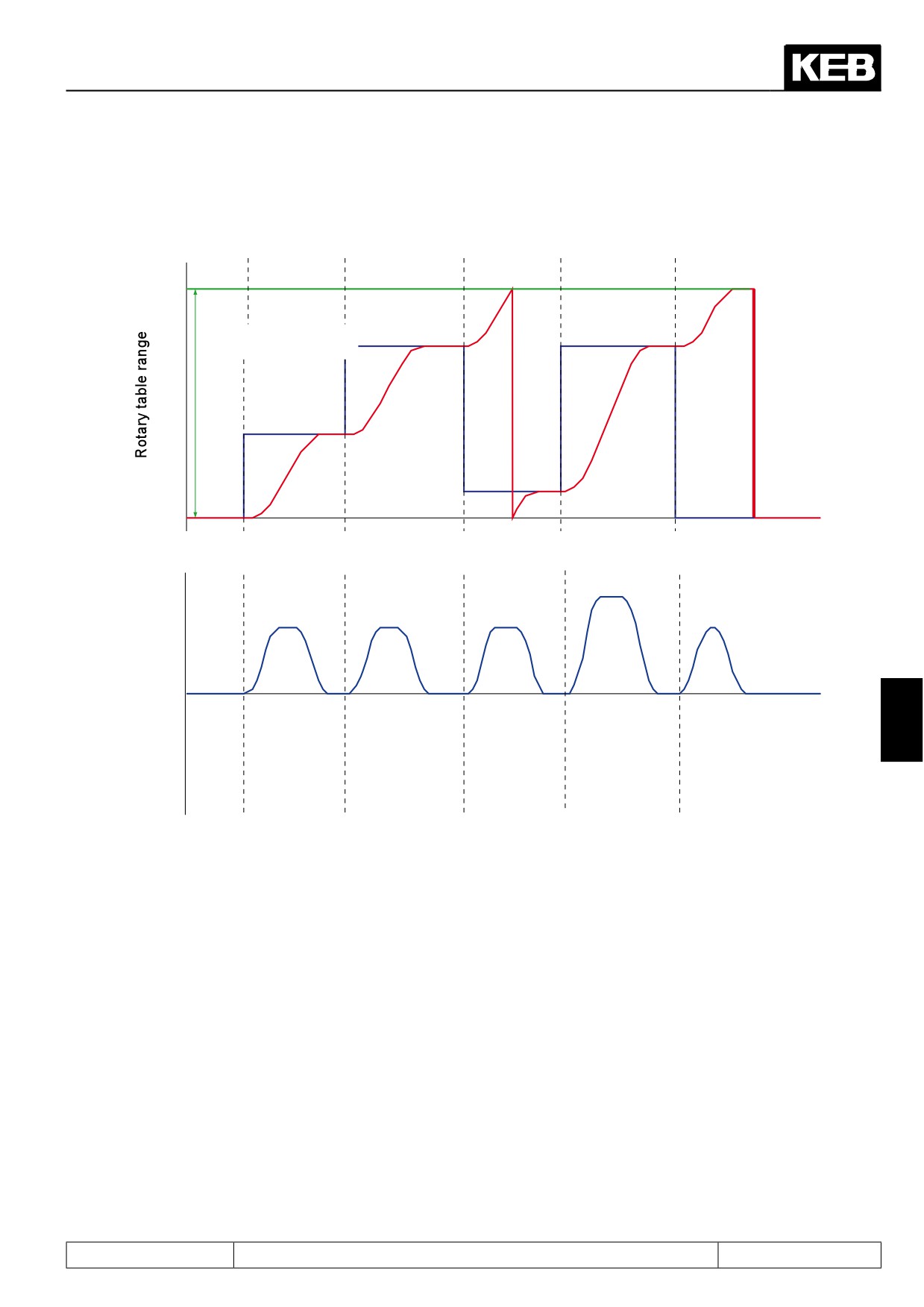
This mode is particularly suitable for round table applications where only one encoder is used for the motor po-
sition. The gear between the motor and the round table can cause the position of the round table to be different
for identical motor positions, depending on the direction of rotation from which the position was approached.
To avoid these problem for applications where the gear backlash cannot be ignored, the target must always be
Page7.12 - 52
Positioning and Synchronous Control
approached from the same direction of rotation. The direction from which a position is approached is deter-
mined by the sign of PS.24 "index position": Positive values mean the position is approached from the right,
negative values lead to an approach from the left.
ru.61: Target position
ru.56: Set position
7
ru.02: Ramp output display (setpoint speed controller)
In this example, all position setpoint in PS.24 are positive. The position values 0 and PS.39 are identical, the-
refore, the value 0 as well as the value PS.39 can be displayed during traversal of the round table range.
Thereby, apparent jumps can occur in the position values if the display changes between the value 0 and
PS.39.
Page7.12 - 53
Positioning and Synchronous Control
Rotary table / flying referencing
If only one encoder is used, the gear can cause a further problem:
If the gear factor x increments per revolution does not result in an integer value, the value for PS.39 cannot be
set exactly.
Example:
Let the gear ratio between motor and round table be 50 : 3
encoder increments per revolution = 2500 and multiple evaluation = 2: 4-fold
50
50
PS.39 =
x encoder increments per revolution x 2mul-
x 10.000 = 16.666,6666
——
——
tiple evaluation =
3
3
In PS.39, however, only integer values can be entered. Thereby, one obtains (for predominant motion in one
direction of rotation) an error that increases with each round table revolution.
To correct for this error, the possibility of flying referencing exists for round table applications.
For that purpose, an initiator is connected to a digital input which generates a pulse at a fixed round table posi-
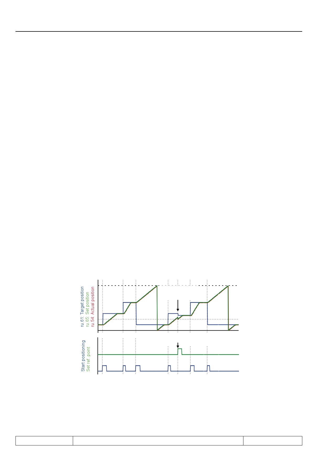
tion. Whenever this pulse is recognised, the actual position must be equal to the position of the initiator. If this
is not the case, the actual position is set to the initiator position. The setpoint- and target position are corrected
by the same value as the actual position.
Example:
The drive rotates clockwise.
The initiator provides a signal at position 1000.
The drive starts at position 0.
The actual position (ru.54) at the time the edge of the initiator is 999.
The set position (ru.56) is 1002, the target position is 5000 increments.
The position range (PS.39) is 10,000 increments.
The actual position is set to 1000, i.e., corrected by +1.
The set point position is set accordingly to 1003 and the target position to 5001.
Act. and set position =
Ref. point (PS.17)
Target position adapted
Clockwise rotation → positive flag
For the positioning for which corrections are made, the value of PS.24 "index position", therefore, does not
match ru.61 "target position" anymore, instead of the value 5000, positioning is done to 5001.
The next position is again approached corresponding to PS.24, i.e., the value of target position (ru.61) and
index position (PS.24) match. Thereby, the error caused by the noninteger gear ratio is compensated.
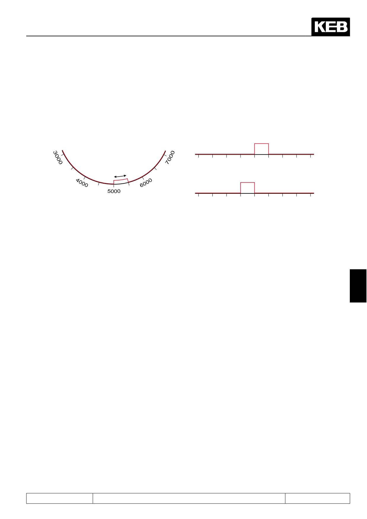
Since the initiator signal is longer than one increment, the same point of the initiator must always be used for
the adjustment. Therefore, adjustments for clockwise direction of rotation is made as soon as the initiator is re-
Page7.12 - 54
Positioning and Synchronous Control
ached (positive edge). For counter clockwise direction of rotation links, adjustments are made when the initiator
is left (negative edge).
Example: The initiator signal is active from Position 5000 to 5500
To have the adjustment executed always at position 5000, adjustments must be executed at the positive edge
for clockwise rotation and at the negative edge for counter clockwise rotation.
Forward
Correction
Initiatior signal
Initiatior signal
3000
4000
5000
6000
7000
Correction
point
Correction
Reward
Initiatior signal
7000
6000
5000
4000
3000
An important point for flying referencing is the suppression of interference pulses that can trigger a referencing
at the wrong position.
Basic requirement is the EMC conform installation. The programming of a digital filter in the di-parameters is
unsuitable for the flying referencing since the time delay caused by the filter distorts the referencing.
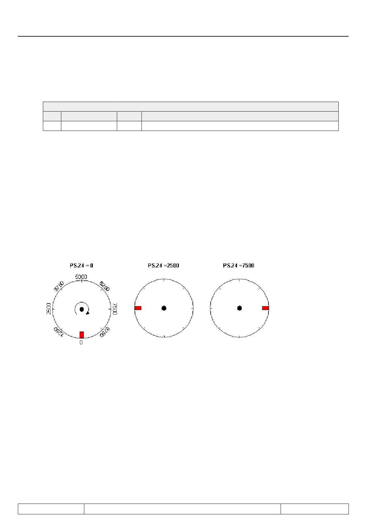
Therefore, there is the parameter PS.40 "reference point window". Only an initiator pulse within the position
window of +/- PS.40 around the reference point PS.17 triggers an adjustment.
Example:
7
PS.17 = 5000 increments / PS.40 = 500
Then, referencing signals are accepted only if the actual position ru.54 is in the range of 4500 to 5500.
The default value for PS.40 is 0, i.e., the interference suppression is switched off.
To receive a warning that interference pulses have occurred, a digital output can be set if a referencing signal
outside of the permitted windows occurs.
To that end, the value 78 "round table reference invalid" must be selected as the switching condition in the do-
parameters. The switching condition is reset with the next "start positioning" command.
Page7.12 - 55
Positioning and Synchronous Control
7.12.4.11
Posi mode / defined stop
In some applications, a drive shall stop within one revolution at a defined position during vector controlled ope-
ration. For such applications, the mode "position specification relative to the null signal" was created.
PS.27: Index mode
Bit
Meaning
Value
Explanation
1...3
Position setting
4
Relative to zero signal
In this application, the functions "position / synchronous activation" and "start positioning" are connected to the
same input. If the signal at this input is not active, the drive runs vector controlled.
If the input is activated, the drive correspondingly delays the defined acceleration-, deceleration- and S-curve-
times. Thereby, it positions to the distance to the marker pulse defined in PS.24. How many revolutions it still
travels during the delay dependent on the speed and the adjusted ramps. Only the position within one revolu-
tion of the position encoder at which the drive stops is defined.
In PS.24 "index/position", only values from 0 to encoder increments per revolution * 2 multiple evaluation may
be
entered in this mode. The direction of rotation from which the position is approached is always the direction of
rotation with which the drive ran before activation of the positioning.
Attention: If the modulation is switched off (switch-off of the control release, error) while the drive rests at the
stopping position, the drive will be in vector controlled operation again after switching on the modulation.
Example: Incremental encoder / 2500 increments / 4-fold evaluation
One application would be, e.g., a drill for which the chuck key must always have a defined position during
standstill.
Page7.12 - 56
Positioning and Synchronous Control
7.12.4.12
Posi mode / remaining distance positioning
The remaining distance positioning is similar to the mode defined stop. Only that here, positioning is done to a
set distance from a marker, rather than to a defined
position within one revolution. The drive comes from vector controlled operation and runs, starting at a marker,
the defined residual distance.
To that end, the value 2: relative must be set in PS.27.
PS.27: Index mode
Bit
Meaning
Value
Explanation
The value of PS.24 index position defines the path that still has to
1..3
Position setting
2: relative
be travelled starting at the positive edge of the marker.
After activation of the positioning mode by a digital input, the drive remains in vector controlled operation,
until the marker triggers a "start positioning" command. The target position for the positioning is the actual po-
sition ru.54 at the time of the positive edge + PS.24 "index position".
PS.24
PS.24
ru.61: Target position
7
ru.54: Actual position
Position-con-
Speed-controlled
Position-controlled
trolled opera-
operation
operation
tion
Start Positioning
Activation positioning/ synchro-
nous
Page7.12 - 57
Positioning and Synchronous Control
7.12.4.13
Posi mode / flying referencing with correction
During the round table positioning with only one encoder for motor and round table position, a flying referencing
for correcting a gear factor error exists. For other applications using only one encoder, one needs compensati-
on for slip (undercarriages) or cable stretch (hoists).
An undercarriage shall, e.g., be moved 1m, corresponding to 10,000 increments. During starting, the powered
wheels slip on the steel rail, however, so that after 10,000 increments of encoder revolution, the undercarriage
has only travelled 0.95m.
To compensate for this error, the slip-afflicted system can be resynchronised via reference markers. There re-
ference markers indicate the real position of the drive. An adjustment value is calculated from this information.
The adjustment is still carried out within one active positioning, to reach the target at the predefined position.
To be able to approach the target from both directions, two reference markers that can be located at different
positions must be supported.
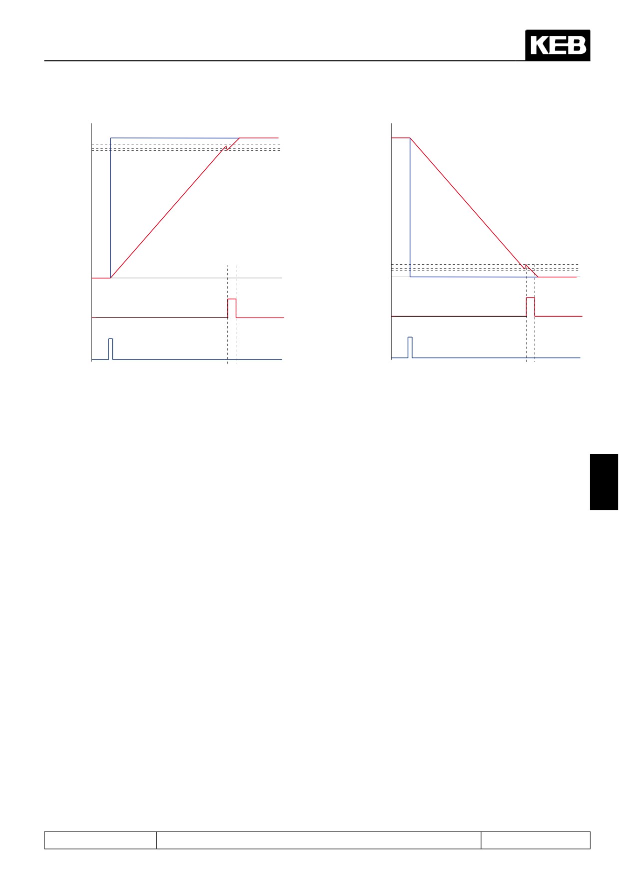
Dependent on the direction of rotation, the positive edge of the reference marker is expected at a distance to
target of PS.46 "relative corr. switch forward" (direction of rotation clockwise) and PS.47 "relative corr. switch
reverse" (direction of rotation counter clockwise), respectively.
In parameter ru.69 "distance ref.-zero point", the adjustment value is displayed. It is calculated as:
Clockwise rotation: ru.69 = PS.46 - (ru.61: target position - ru.56: set position)
Counter clockwise rotation: ru.69 = (ru.61: target position - ru.56: set position) - PS.47
Example:
An undercarriage shall drive to the position 5m (= 5,000 increments).
The undercarriage loses 0.2m (= 200 increments) during acceleration due to slip.
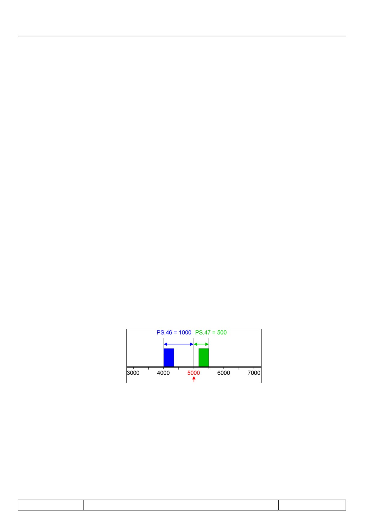
The right reference marker is situated at position 4...4.3m => PS.46 = 1m = 1,000.
The left reference marker is situated at position 5.2...5.5m => PS.47 = 0.5m = 500.
Target
Clockwise rotation:
Counter clockwise rotation:
Page7.12 - 58
Positioning and Synchronous Control
ru.61: Target posi-
tion
ru.56 Set position
Ref.-marker
Start positioning
Attention: No reference point setting of the actual position takes place. This has the following con-
sequence: If the position controller is not active (PS.06 = 0), or if the drive cannot follow
the setpoint position due to torque limits or controller settings, errors in the actual po-
sition can add up.
If the referencing marker is recognised only during the deceleration ramp when reaching the target, the target
7
position cannot be reached with the adjusted ramps anymore.
During the constant running phase, too, the adjustment of the position via the reference markers can lead to
the target position not being reachable anymore. This is possible every time the reference marker shows that
the drive is already nearer the target than expected.
To be able to directly drive to the target in these cases as well, the ramp times must be changed.
In parameter PS.44 "limit acc/dec corr. %", a factor between 25 and 100% can be set. 25% means that the
deceleration times may be reduced to maximally 25% and increased by up to a factor of 4. The value 33% in
PS.44 would correspondingly allow a change in the deceleration times of between 33% and a factor of 3 of the
values set in the oP-parameters.
If the adjustment pulse is received when the drive is already in the deceleration phase, adjustment occurs only
during the last S-curve before reaching the target.
If the change of the ramp times by the adjusted adjustment factor PS.44 is insufficient, the drive enters the
status "position inaccessible".
Page7.12 - 59
Positioning and Synchronous Control
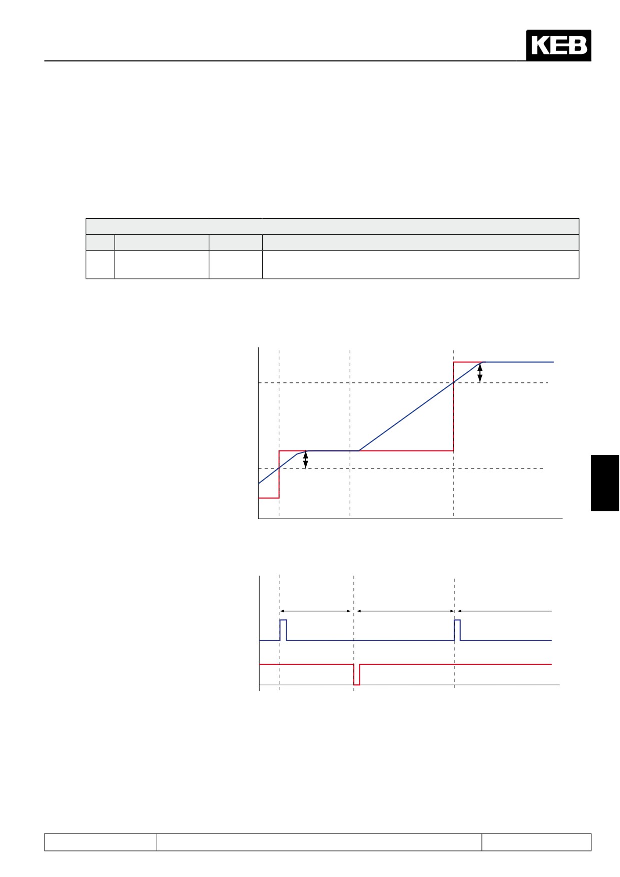
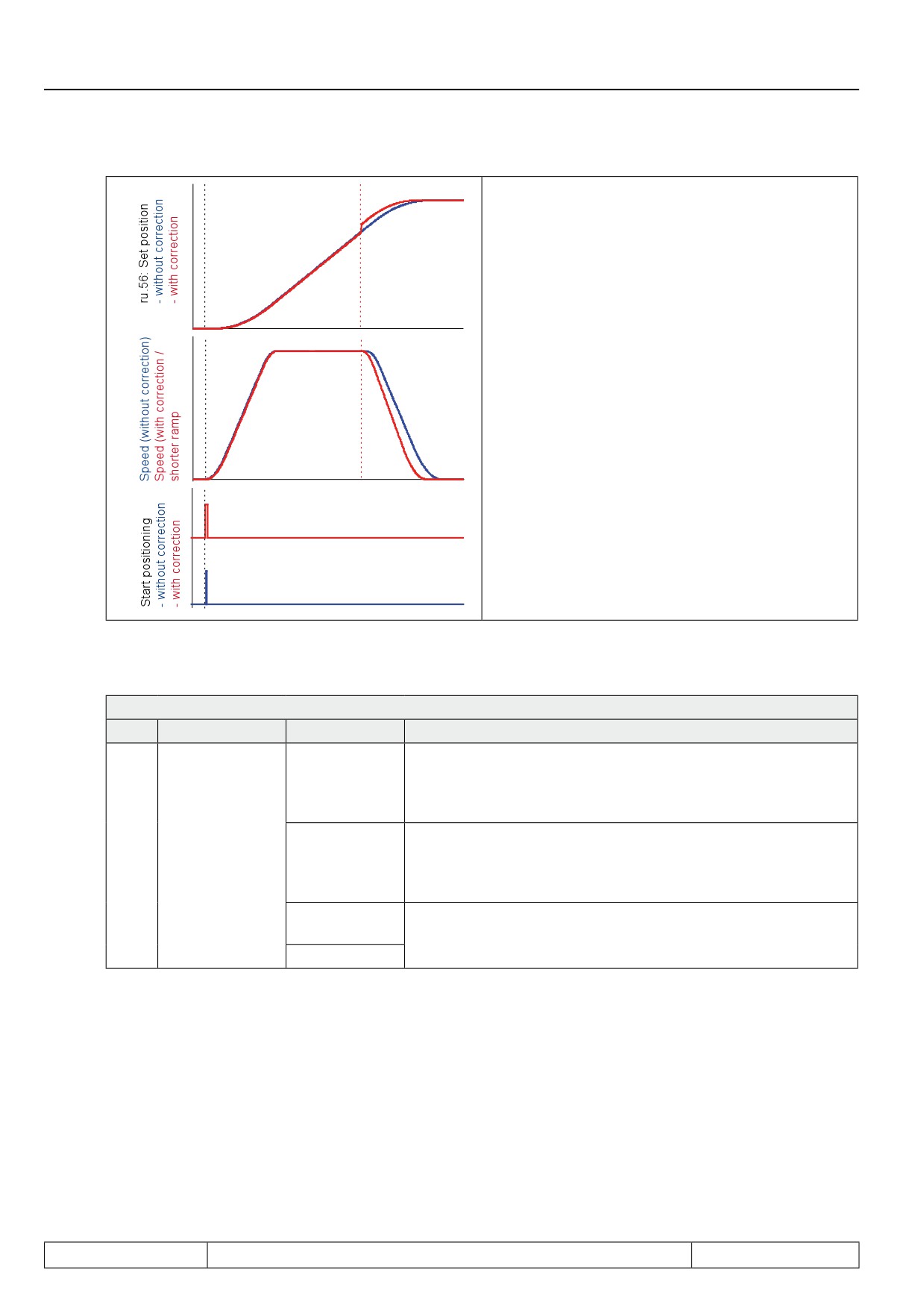
The blue curve shows a positioning where the refe-
rence marker does not trigger an adjustment.
For the red curve, it is
determined at the reference marker that the drive is
closer to the target than expected.
If breaking would occur at the adjusted deceleration
times
, the target would be overshot.
Via PS.44 = 25% the drive is permitted to decelerate
more sharply.
The comparison of the red and the blue speed curve
show that the drive accelerates equally in both cases,
but decelerates more sharply after the adjustment.
Thereby, the adjustment can be still be carried out
during the running positioning and the target position
can still be reached.
If no successful adjustment can be executed during the running positioning, there are two different response
options which can be selected via PS.00:
PS.00: Posi / synchronous mode
Bit
Meaning
Value
Explanation
If the target position is inaccessible due to the adjustment, even
with the adjusted ramp times, the drive stops and posts the sta-
0: stop
tus message "123: position inaccessible". This status can be re-
set only by deactivation of the positioning module.
If the target position is inaccessible due to the adjustment with
If position not re-
6 / 7
64: stop + new
the precept ramps, the drive completes the original positioning
achable
attempt
profile and then automatically starts a new positioning to reach
the target position.
128: new at-
tempt
Do not use
192: reserved
Page7.12 - 60
Positioning and Synchronous Control
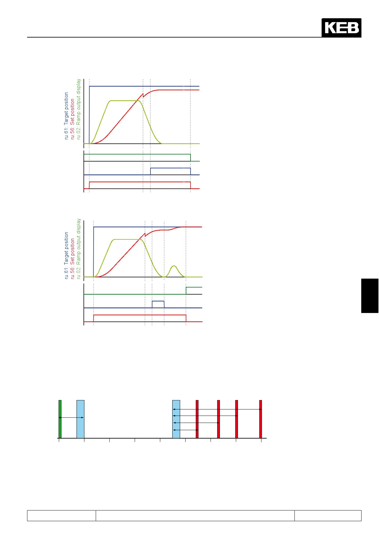
PS.00 / bit 6...7 = 0: Stop
Reference marker recognised during the deceleration
phase of the target approach.
Adjustment of the position is executed, but positio-
ning to the target position is not possible anymore.
(S-curve-time too small or adjustment factor for ramps
in PS.44 set too small).
With the beginning of the lower S-curve, the drive si-
gnals "position inaccessible"via a digital output.
Posi / sync
Only with deactivation of the positioning module, the
activation
output "target inaccessible" is reset.
Target not
reachable
Profile
processing
active
PS.00 / bit 6...7 = 64: Stop + new attempt
Reference marker recognised during the deceleration
phase of the target approach.
Adjustment of the position is executed, but positio-
ning to the target position is not possible anymore.
With the beginning of the lower S-curve, the drive si-
gnals "position inaccessible"via a digital output
After reaching standstill, the drive automatically starts
Target
a new positioning to the target position.
window
The output "target inaccessible" is reset automatical-
reached
7
Target not
ly
reachable
The two reference markers belong to the block (in-
Profile
dex) that defines a positioning step.
processing
active
The two reference markers belong to the block (index) that defines a positioning step. (For the description of
the positioning indexes see chapter 7.12.4.8 "sequential positioning"). In connection with the reference marker,
it is useful to define index blocks even for single positionings.
Example:
Start
Target 1
Target 2 Target 3
Target 4
PS.46 = 3500
PS.46 = 2500
PS.47 = 1000
PS.46 = 1750
PS.46 = 1000
1000
2000
3000
4000
5000
6000
7000
8000
Reference mark 1
Reference mark 2
Page7.12 - 61
Positioning and Synchronous Control
From a starting position, an undercarriage shall drive to 4 different positions . The positions of target 1...4 are
always approached from the left, the start always from the right. For the targets, therefore, reference markers
are always defined for clockwise rotation, and for the start only a reference marker for counter clockwise rota-
tion. The values for the other reference markers are set to zero (= deactivated)
The profile speed definition is given via parameter PS.31 "max. speed setting %". I.e., in PS.00 / bit 5, "positio-
ning / target speed" the value "16: PS.31 / PS.25" must be entered.
The drive shall stop at the target, in Parameter PS.25 "index speed", the
value 0 must therefore be entered for all blocks.
This is a single positioning, PS.26 "next index" must always be set to "-1: PS.28", since there is no next position.
The positions are set as absolute values and "continuation of the profile processing" is deactivated. Parameter
PS.27 must therefore be set to the value 0.
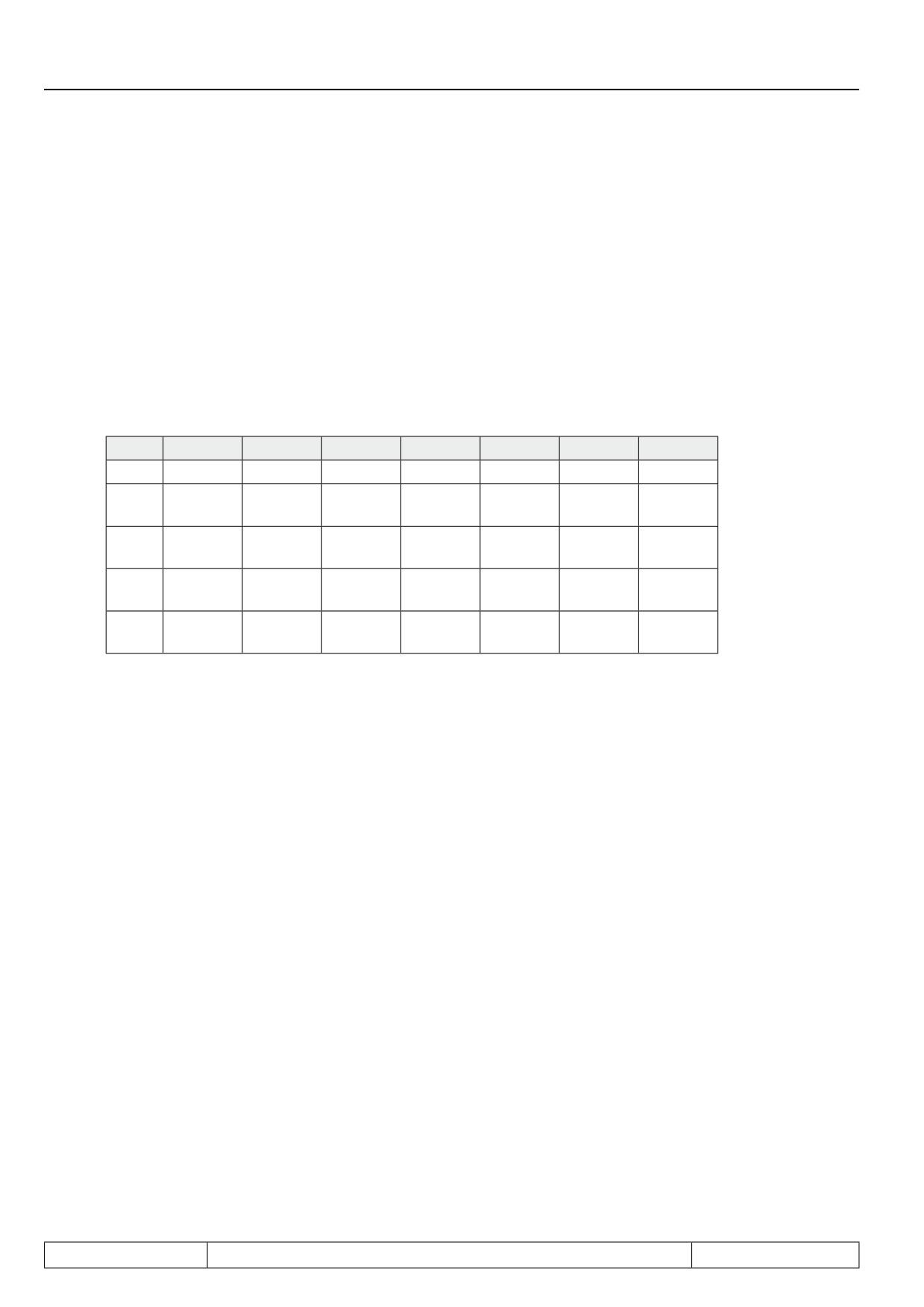
This results in the following positioning blocks:
PS.23
PS.24
PS.25
PS.26
PS.27
PS.46
PS.47
Start
0
0
0
-1:PS.28
0
0: off
1000
Ta r -
1
5500
0
-1:PS.28
0
1000
0: off
get 1
Ta r -
2
6250
0
-1:PS.28
0
1750
0: off
get 2
Ta r -
3
7000
0
-1:PS.28
0
2500
0: off
get 3
Ta r -
4
8000
0
-1:PS.28
0
3500
0: off
get 4
If the drive shall now travel from the start to target 2, the value 2 must be entered in parameter PS.28 "start
index new profile", and the "start positioning" command must then be given.
In the process, the undercarriage also crosses reference marker 1, which can trigger an adjustment only during
the positioning to the starting point. For the drive to target 2, marker 1 must be ignored. For that purpose, the
parameter PS.40 "reference point window" is used. Only an initiator pulse within the position window of +/-
PS.40 around the programmed value for the reference marker triggers an adjustment.
Example target 2:
PS.46 = 1750 increments / PS.24 = 6250 → the reference marker is expected at 6250 - 1750 = 4500.
If the reference point window is set to, e.g., 300 increments, the initiator signal is accepted only if the drive
rotates in clockwise direction of rotation and as long as the actual position ru.54 is in the range of 4200 to 4800
increments.
The size of the reference point window depends on the maximum expected slip. If one assumes that maximally
150 increments "are lost" due to the slipping of the wheels (i.e., are not converted to propulsion), a value > 150
increments must be set in PS.40 .
If the drive is approaching target 2 from the left, reference marker 1 generates a positive edge at an actual po-
sition of 700...850 (depending on the level of slippage) and therefore outside of the permitted window.
This marker is therefore ignored. Reference marker 2 generates its pulse within the reference window and is
evaluated for the adjustment.
Page7.12 - 62
Positioning and Synchronous Control
Example start position:
To drive back to the starting position, the value 0 must be entered in Parameter PS.28 "start index new profile"
and the "start positioning" command must be given. The drive then travels back to the start with direction of
rotation counter clockwise.
PS.47 = 1000 increments / PS.24 = 0 → the reference marker is expected at 0 + 1000 = 1000.
PS.40 "reference point window" = 300 increments
The initiator signal is evaluated only if the direction of rotation is counter clockwise and the actual position lies
within a range of 700...1300 increments. With this, the reference marker 2 is masked for the return path.
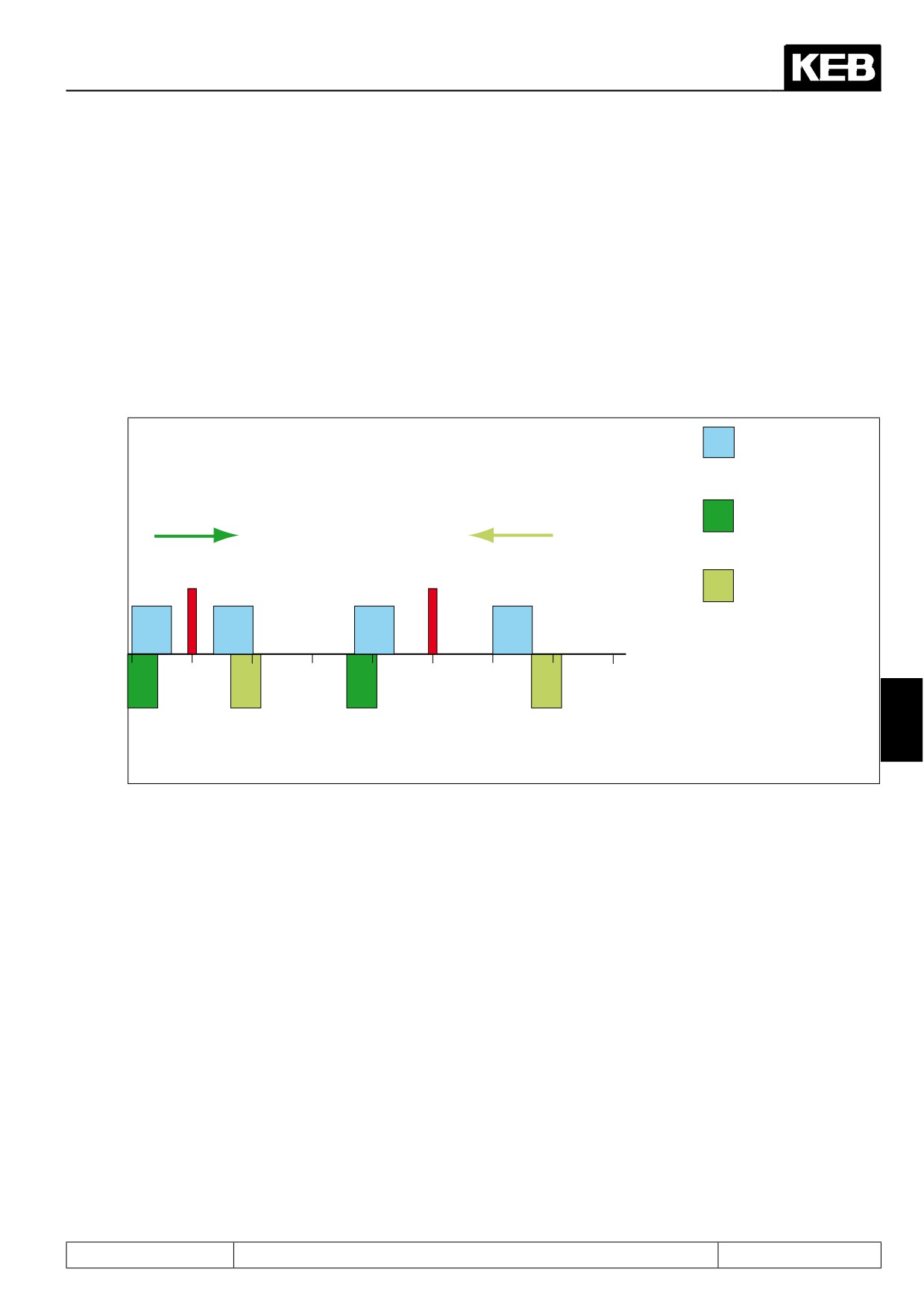
The following figure illustrates the connection between direction of rotation, target, the values of PS.46 / 47 and
the reference point window PS.40.
Reference mark (300
increments)
Direction of rotation
Direction of rotation
Valid range for the target
clockwise
counter clockwise
at direction of rotation
clockwise
Target A
Target B
Valid range for the target
at direction of rotation
counter clockwise
M
M
M
M
4000
5000
6000
7000
GA
GA
GB
GB
Index A:
Index B:
7
PS.24 = 4000
PS.24 = 6000
PS.46 = 500
PS.46 = 650
PS.47 = 500
PS.47 = 800
The parameter PS.45 "index selection corr." is identical to parameter PS.23 "index selection". It has been in-
serted here a second time only to simplify the operation.
7.12.4.14
Posi mode / start positioning
A "start positioning" command can be generated by various means:
● via digital input
The digital input is selected via parameter PS.29 "start positioning input selection". Alternatively, the
function "start positioning" can be associated with an input in the parameters di.11...di.22 (see chapter
7.3 digital inputs)
● by means of the control word Sy.50 or Sy.43
To start the positioning by means of the control word Sy.43 ("control word long") and Sy.50 ("control word
low"), respectively, bit 10 "start positioning" must be switched from 0 to 1.
Page7.12 - 63